Embed Size (px)
Citation preview
TADANO ROUGH TERRAIN CRANE
MODEL : GR-600EX
(Left-hand steering)
GENERAL DATA
CRANE CAPACITY 60,000 kg at 3.0 m
BOOM 5-section, 11.0 m 43.0 m
DIMENSION
Overall length approx. 13,380 mm Overall width approx. 3,315 mm Overall height approx. 3,790 mm
MASS
Gross vehicle mass approx. 43,735 kg -front axle approx. 21,555 kg -rear axle approx. 22,180 kg
PERFORMANCE
Max. traveling speed computed 36 km/h Gradeability (tan q ) computed 147 % (at stall)
*30 %
* Machine should be operated within the limit of engine crankcase design (17o : MITSUBISHI 6M60-TL).
Specifications are subject to change without notice.
SPEC. SHEET No. GR-600E-2-00302/C-03
- 1 -
DATE May ,2015
CRANE SPECIF ICATIONS
MODEL GR-600EX
CAPACITY 60,000 kg at 3.0 m
BOOM Five section full power partially synchronized telescoping boom of round box construction with 5 sheaves at boom head. The synchronization system consists of 2 telescope cylinders, extension cables and retraction cables. Hydraulic cylinders fitted with holding valves.
Fully retracted length. . . . . . . . 11.0 m Fully extended length. . . . . . . . 43.0 m Extension speed. . . . . . . . . . . . 32.0 m in 128 s
JIB Two staged swingaround boom extension. Triple offset (3.5o/25o/45o) type. Stores alongside base boom section. Assistant cylinders for mounting and stowing. Single sheave at jib head.
Length. . . . . . . . . . . . . . . . . . . . 10.1 m and 17.7 m
SINGLE TOP (AUXILIARY Single sheave. BOOM SHEAVE) Mounted to main boom head for single line work.
ELEVATION By a double-acting hydraulic cylinder, fitted with holding valve. Automatic speed reduction and soft stop function.
Boom angle . . . . . . . . . . . . . . . . –1.6o to 80.3o Boom raising speed. . . . .. . . . . . 20o to 60o in 46 s
HOIST - Main winch Variable speed type with grooved drum driven by hydraulic axial piston motor through winch speed reducer. Power load lowering and hoisting. Equipped with automatic brake (Neutral brake) and counterbalance valve. Controlled independently of auxiliary winch.
Single line pull. . . . . . . . . . . . . 54.9 kN {5,600 kgf} Single line speed. . . . . . . . . . . 136 m/min (at the 4th layer) Wire rope. . . . . . . . . . . . . . . . . Spin-resistant type
Diameter x length. . . . . . . . 19 mm x 235 m
HOOK BLOCK(Optional) - 6 sheaves, swivel type hook with safety latch. 60 t capacity
HOOK BLOCK(Optional) - 3 sheaves, swivel type hook with safety latch. 35 t capacity
SPEC. SHEET No. GR-600E-2-00302/C-03
- 2 -

HOIST - Variable speed type with grooved drum driven by hydraulic axial piston Auxiliary winch motor through winch speed reducer. Power load lowering and hoisting.
Equipped with automatic brake (Neutral brake) and counterbalance valve. Controlled independently of main winch.
Single line pull. . . . . . . . . . . . . 54.9 kN {5,600 kgf} Single line speed. . . . . . . . . . . 136 m/min (at the 4th layer) Wire rope. . . . . . . . . . . . . . . . . Spin-resistant type
Diameter x length. . . . . . . . 19 mm x 133 m
HOOK BLOCK - Swivel hook with safety latch for single line use. 5.6 t capacity
SLEWING Hydraulic axial piston motor driven through planetary speed reducer. Continuous 360o full circle slew on ball bearing slew ring. Equipped with manually locked / released slewing brake.
Slewing speed. . . . . . . . . . . . . . . 2.4 min-1 {rpm}
HYDRAULIC SYSTEM Pumps. . . . . . . . . . 2 variable piston pumps for telescoping, elevating and winches. Tandem gear pump for steering, slewing and optional equipment.
Control valves. . . . . Multiple valves actuated by pilot pressure with integral pressure relief valves.
Circuit. . . . . . . . . . . Equipped with air cooled type oil cooler. Oil pressure appears on AML display for main circuit.
Hydraulic oil tank capacity. . . approx. 840 liters
Filters. . . . . . . . . . . Return line filter
CRANE CONTROL By 4 control levers for swing, boom hoist, main winch, boom telescoping or auxiliary winch with 2 control pedals for boom hoist and boom telescoping based on ISO standard layout. Control lever stands can change neutral positions and tilt for easy access to cab.
SPEC. SHEET No. GR-600E-2-00302/C-03
- 3 -
CAB Both crane and drive operations can be performed from one cab mounted on rotating superstructure. One sided one-man type, steel construction with sliding door access and tinted safety glass windows opening at side. Door window is powered control. Operator's 3 way adjustable seat with headrest and armrest. Hot water cab heater and air conditioning.
TADANO Automatic Main unit in crane cab gives audible and visual warning of approach to Moment Limiter overload. Automatically cuts out crane motions before overload. With (Model: AML-C) working range (load radius and / or boom angle and / or tip height and/or
slewing range) limit function. Automatic Speed Reduction and Slow Stop function on boom elevation and slewing. Following functions are displayed. Moment load as percentage Number of parts of line of rope Boom angle Boom length Load radius Outriggers position On-tire indicator Actual hook load Permissible load Boom position indicator Potential hook height Slewing angle Main hydraulic oil pressure Jib length and jib offset angle (only when jib operation)
OUTRIGGERS Hydraulically operated H-type outriggers. Each outrigger controlled simultaneously or independently from the cab. Equipped with sight level gauge. Floats mounted integrally with the jacks retract to within vehicle width. All cylinders fitted with pilot check valves. Crane operation with different extended length of each outrigger. Equipped with extension width detector for each outrigger.
Extended width Fully. . . . . . . . . . . 7,300 mm Middle. . . . . . . . . 6,700 mm Middle. . . . . . . . . 5,500 mm Minimum. . . . . . . 2,700 mm
Float size (Diameter). . . . . . . 600 mm
COUNTERWEIGHT Integral with swing frame (containing weight with auxiliary winch and wirerope)
Mass. . . . . . . . . . 5,670 kg
-------------------------------------------------------------------------------------------------------------------------------------- NOTE : Each crane motion speed is based on unladen conditions.
SPEC. SHEET No. GR-600E-2-00302/C-03
- 4 -
CARRIER SPECIF ICATIONS
TYPE Rear engine, left-hand steering, driving axle 2-way selected type (by manual switch).
4 x 2 front drive 4 x 4 front and rear drive
FRAME High-tensile steel, all welded mono-box construction.
ENGINE Model. . . . MITSUBISHI 6M60-TLC1B GB20891-2007Ⅱ Type. . . . . 4 cycle, turbo charged and after cooled, 6 cylinder in line, direct
injection, water cooled diesel engine. Piston displacement. . . . . 7,545 cm3 Bore x stroke. . . . . . . . . . 118 mm x 115 mm Max. output. . . . . . . . . . . . 200 kW at 2,600 min-1 {rpm} Max. torque. . . . . . . . . . . . 785 N・m at 1,400 min-1 {rpm}
TRANSMISSION Electronically controlled full automatic transmission. Torque converter driving full powershift with driving axle selector. 6 forward and 2 reverse speeds. 3 speeds - High range - 2 wheel drive ; 4 wheel drive 3 speeds - Low range - 4 wheel drive
AXLES Front. . . . . Full floating type, steering and driving axle with planetary reduction.
Rear. . . . . Full floating type, steering and driving axle with planetary reduction. Non-spin differential.
STEERING Hydraulic power steering controlled by steering wheel. Four steering modes available:
2-wheel front 2-wheel rear 4-wheel coordinated 4-wheel crab
SUSPENSION Front. . . . . Rigid mounted to the frame. Rear. . . . . Pivot mounted with hydraulic lockout cylinders.
BRAKE SYSTEM Service. . . Air over hydraulic disc brakes on all 4 wheels. Parking / Emergency. . .
Spring applied-air released brake acting on input shaft of front axle.
Auxiliary. . . Electro-pneumatic operated exhaust brake.
ELECTRIC SYSTEM 24 V DC. 2 batteries of 12 V - 120 Ah capacity.
FUEL TANK CAPACITY 300 liters
TIRES Front.......29.5–25 22PR(OR) , Single x 2 Air pressure:350 kPa or 29.5–25 28PR(OR) , Single x 2 Air pressure:330 kPa
Rear........29.5–25 22PR(OR), Single x 2 Air pressure:350 kPa or 29.5–25 28PR(OR), Single x 2 Air pressure:330 kPa
TURN RADIUS Min. turning radius (at center of extreme outer tire) 2-wheel steering. . . . . . . . 11.9 m 4-wheel steering. . . . . . . . . 6.8 m
SPEC. SHEET No. GR-600E-2-00302/C-03
- 5 -
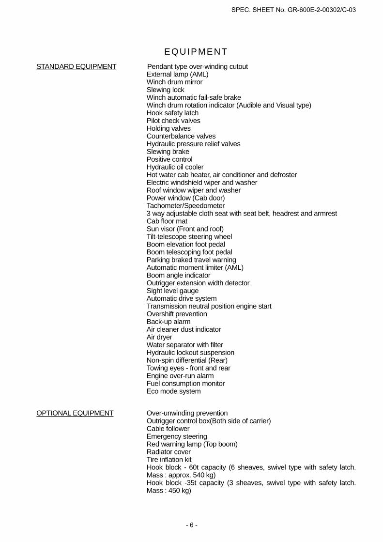
EQUIPMENT STANDARD EQUIPMENT Pendant type over-winding cutout
External lamp (AML) Winch drum mirror Slewing lock Winch automatic fail-safe brake Winch drum rotation indicator (Audible and Visual type) Hook safety latch Pilot check valves Holding valves Counterbalance valves Hydraulic pressure relief valves Slewing brake Positive control Hydraulic oil cooler Hot water cab heater, air conditioner and defroster Electric windshield wiper and washer Roof window wiper and washer Power window (Cab door) Tachometer/Speedometer 3 way adjustable cloth seat with seat belt, headrest and armrest Cab floor mat Sun visor (Front and roof) Tilt-telescope steering wheel Boom elevation foot pedal Boom telescoping foot pedal Parking braked travel warning Automatic moment limiter (AML) Boom angle indicator Outrigger extension width detector Sight level gauge Automatic drive system Transmission neutral position engine start Overshift prevention Back-up alarm Air cleaner dust indicator Air dryer Water separator with filter Hydraulic lockout suspension Non-spin differential (Rear) Towing eyes - front and rear Engine over-run alarm Fuel consumption monitor Eco mode system
OPTIONAL EQUIPMENT Over-unwinding prevention Outrigger control box(Both side of carrier) Cable follower Emergency steering Red warning lamp (Top boom) Radiator cover Tire inflation kit Hook block - 60t capacity (6 sheaves, swivel type with safety latch. Mass : approx. 540 kg) Hook block -35t capacity (3 sheaves, swivel type with safety latch. Mass : 450 kg)
SPEC. SHEET No. GR-600E-2-00302/C-03
- 6 -
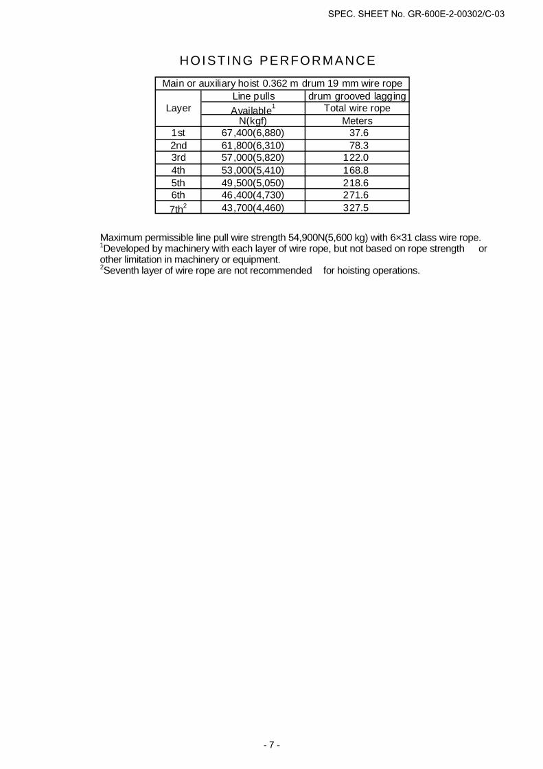
HOISTING PERFORMANCE
Maximum permissible line pull wire strength 54,900N(5,600 kg) with 6×31 class wire rope. 1Developed by machinery with each layer of wire rope, but not based on rope strength or
other limitation in machinery or equipment. 2Seventh layer of wire rope are not recommended for hoisting operations.
Line pulls drum grooved laggingAvailable1 Total wire rope
N(kgf) Meters1st 67,400(6,880) 37.62nd 61,800(6,310) 78.33rd 57,000(5,820) 122.04th 53,000(5,410) 168.85th 49,500(5,050) 218.66th 46,400(4,730) 271.67th2 43,700(4,460) 327.5
Layer
Main or auxiliary hoist 0.362 m drum 19 mm wire rope
SPEC. SHEET No. GR-600E-2-00302/C-03
- 7 -

AB C C C C C C C C C C
3.0 68 60.0 74 40.8 78 32.0 78 22.0 3.5 65 54.9 72 40.8 76 32.0 76 22.0 4.0 62 53.8 70 40.8 75 32.0 75 22.0 4.5 59 47.7 68 40.8 73 32.0 73 22.0 78 22.0 78 17.0 5.0 56 42.8 66 40.8 72 32.0 72 22.0 77 21.3 77 17.0 5.5 52 38.7 64 37.5 70 32.0 70 22.0 76 20.3 76 17.0 6.0 48 35.3 61 34.6 68 31.9 68 22.0 75 19.4 75 17.0 6.5 44 32.4 59 32.0 67 30.3 67 22.0 74 18.6 74 16.2 79 14.0 79 12.0 7.0 39 29.9 57 29.6 65 28.8 65 22.0 73 17.8 73 15.6 78 13.5 78 11.7 7.5 34 27.7 54 27.4 64 25.8 63 22.0 72 17.7 72 14.9 77 13.0 77 11.3 8.0 28 25.7 52 24.9 62 23.2 61 22.0 71 17.6 71 14.4 76 12.6 76 10.9 78 10.0 8.5 20 22.6 49 22.0 60 21.0 60 22.0 70 17.5 70 13.9 75 12.2 76 10.5 77 10.0 9.0 47 19.5 58 19.1 58 21.7 68 17.4 69 13.4 75 11.9 75 10.2 76 10.0 80 9.010.0 40 15.8 54 15.3 54 17.8 66 15.7 66 12.4 73 11.8 73 9.5 75 9.6 78 8.711.0 34 13.0 50 12.6 50 15.0 64 13.6 64 11.5 71 11.6 71 8.9 73 9.1 77 8.312.0 25 10.9 46 10.5 46 12.8 62 11.6 62 10.6 69 11.4 70 8.5 72 8.6 75 7.914.0 36 7.6 36 9.7 56 8.6 56 9.3 66 9.1 66 7.7 69 7.9 72 7.416.0 22 5.5 21 7.5 51 6.5 51 7.9 62 7.0 62 6.7 66 7.4 71 7.318.0 45 5.0 45 6.4 58 5.5 58 5.9 62 6.1 66 5.720.0 39 3.9 38 5.2 54 4.4 54 5.2 59 4.9 63 4.622.0 30 3.1 29 4.3 50 3.5 50 4.5 55 4.1 60 3.724.0 17 2.4 17 3.6 45 2.8 46 3.7 51 3.3 56 3.026.0 40 2.2 40 3.2 47 2.8 53 2.428.0 34 1.7 34 2.7 43 2.3 49 1.930.0 27 1.3 27 2.3 38 1.9 45 1.532.0 16 1.0 16 1.9 32 1.5 41 1.234.0 25 1.2 36 0.936.0 14 1.0
D
Telescopingmode
2nd boom
3rd boom
4th boom
Top boom
A C B B B B B B B B B
0o 8.8 13.6 12.9 7.5 16.9 4.8 16.8 6.2 24.9 2.1 24.6 3.4 32.9 0.9 32.7 1.7 36.3 0.8Telescoping
mode
A :Boom length(m)
B :Load radius(m)
C :Loaded boom angle (o)
D :Minimum boom angle (o) for indicated length (no load)
I, II I I II IIIII II I
LIFTING CAPACITIES AT ZERO DEGREE BOOM ANGLE ON OUTRIGGERS FULLY EXTENDED 7.3 m SPREAD 360o ROTATION
11.0 m 15.0 m 19.0 m 27.0 m 35.0 m 39.0 m
I I
0 0 0 330 50
RATED LIFTING CAPACITIES
II I, II50 100
IITelescoping conditions (%)
I
ISO 4305
I, II
100
1000100 100
66100
1006666
33 100 10033
I II
1000
6633
0 0 00 0 0
27.0 m
10033 33 1006666
II0 100
0 27
11.0 m 15.0 m 19.0 m
ON OUTRIGGERS FULLY EXTENDED 7.3 m SPREAD360o ROTATION (Unit: x 1,000 kg)
35.0 m 39.0 m 43.0 m
SPEC. SHEET No. GR-600E-2-00302/C-03
- 8 -
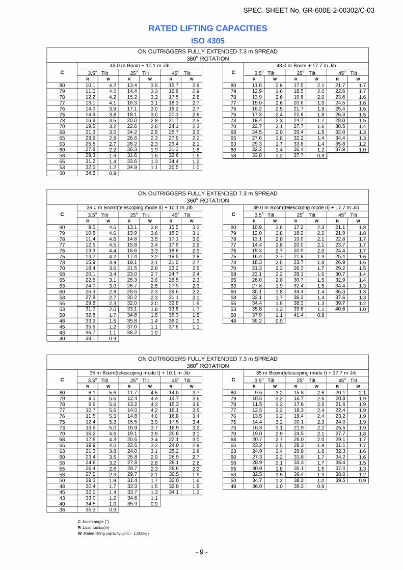
R W R W R W R W R W R W80 10.1 4.2 13.4 3.5 15.7 2.9 80 11.6 2.6 17.5 2.1 21.7 1.779 11.0 4.2 14.4 3.3 16.6 2.9 79 12.9 2.6 18.5 2.0 22.6 1.778 12.2 4.2 15.2 3.2 17.5 2.8 78 13.9 2.6 19.8 2.0 23.6 1.677 13.1 4.1 16.3 3.1 18.3 2.7 77 15.0 2.6 20.6 1.9 24.5 1.676 14.0 3.9 17.1 3.0 19.2 2.7 76 16.2 2.5 21.7 1.9 25.4 1.675 14.9 3.8 18.1 3.0 20.1 2.6 75 17.3 2.4 22.8 1.8 26.3 1.573 16.8 3.5 20.0 2.8 21.7 2.5 73 19.4 2.3 24.7 1.7 28.0 1.570 19.5 3.2 22.6 2.6 24.1 2.3 70 22.7 2.1 27.7 1.6 30.5 1.468 21.3 3.0 24.2 2.5 25.7 2.3 68 24.5 2.0 29.4 1.5 32.0 1.365 23.9 2.8 26.6 2.3 27.9 2.2 65 27.6 1.8 32.2 1.4 34.4 1.363 25.5 2.7 28.2 2.3 29.4 2.1 63 29.3 1.7 33.8 1.4 35.8 1.260 27.8 2.2 30.3 1.9 31.3 1.8 60 32.2 1.4 36.4 1.2 37.9 1.058 29.3 1.9 31.6 1.6 32.6 1.5 58 33.8 1.2 37.7 0.955 31.2 1.4 33.6 1.3 34.4 1.253 32.6 1.2 34.9 1.1 35.5 1.050 34.5 0.9
R W R W R W R W R W R W80 9.5 4.6 13.1 3.8 15.5 3.2 80 10.9 2.8 17.2 2.3 21.1 1.879 10.5 4.6 13.9 3.6 16.2 3.1 79 12.0 2.8 18.2 2.2 21.9 1.878 11.4 4.6 14.8 3.5 17.1 3.0 78 13.1 2.8 19.0 2.1 22.8 1.777 12.5 4.5 15.8 3.4 17.9 2.9 77 14.4 2.8 20.0 2.1 23.7 1.776 13.3 4.4 16.6 3.3 18.6 2.9 76 15.3 2.7 20.9 2.0 24.4 1.775 14.2 4.2 17.4 3.2 19.5 2.8 75 16.4 2.7 21.9 1.9 25.4 1.673 15.9 3.9 19.1 3.1 21.0 2.7 73 18.3 2.5 23.7 1.8 26.9 1.670 18.4 3.6 21.5 2.8 23.2 2.5 70 21.3 2.3 26.3 1.7 29.2 1.568 20.1 3.4 23.0 2.7 24.7 2.4 68 23.1 2.2 28.1 1.6 30.7 1.465 22.5 3.1 25.3 2.6 26.5 2.3 65 26.0 2.0 30.7 1.5 32.9 1.463 24.0 3.0 26.7 2.5 27.9 2.3 63 27.8 1.9 32.4 1.5 34.4 1.360 26.3 2.8 28.6 2.3 29.6 2.2 60 30.1 1.8 34.4 1.4 36.3 1.358 27.8 2.7 30.2 2.3 31.1 2.1 58 32.1 1.7 36.2 1.4 37.6 1.355 29.8 2.3 32.0 2.0 32.8 1.9 55 34.4 1.5 38.3 1.3 39.7 1.253 31.0 2.0 33.1 1.8 33.8 1.7 53 35.8 1.3 39.6 1.1 40.6 1.050 32.8 1.7 34.8 1.5 35.3 1.5 50 37.9 1.1 41.4 0.948 33.9 1.5 35.8 1.4 36.2 1.3 48 39.2 0.945 35.6 1.2 37.0 1.1 37.6 1.143 36.7 1.1 38.2 1.040 38.1 0.9
R W R W R W R W R W R W80 8.1 5.6 11.7 4.5 14.0 3.7 80 9.6 3.2 15.8 2.6 20.1 2.179 9.1 5.6 12.4 4.4 14.7 3.6 79 10.5 3.2 16.7 2.6 20.8 1.978 9.9 5.6 13.2 4.3 15.3 3.6 78 11.5 3.2 17.6 2.5 21.6 1.977 10.7 5.6 14.0 4.2 16.1 3.5 77 12.5 3.2 18.3 2.4 22.4 1.976 11.5 5.5 14.8 4.0 16.8 3.4 76 13.5 3.2 19.4 2.4 23.2 1.975 12.4 5.3 15.5 3.9 17.5 3.4 75 14.4 3.2 20.1 2.3 24.0 1.973 13.9 5.0 16.9 3.7 18.9 3.2 73 16.3 3.1 21.9 2.2 25.5 1.970 16.2 4.6 19.1 3.5 20.8 3.1 70 19.0 2.9 24.5 2.1 27.7 1.868 17.8 4.3 20.6 3.4 22.1 3.0 68 20.7 2.7 26.0 2.0 29.1 1.765 19.9 4.0 22.6 3.2 24.0 2.9 65 23.2 2.5 28.3 1.9 31.1 1.763 21.3 3.8 24.0 3.1 25.2 2.8 63 24.9 2.4 29.8 1.8 32.3 1.660 23.4 3.6 25.8 2.9 26.9 2.7 60 27.3 2.2 31.8 1.7 34.2 1.658 24.6 3.2 27.8 2.8 28.1 2.6 58 28.9 2.1 33.3 1.7 35.4 1.555 26.4 2.6 28.7 2.3 29.6 2.2 55 30.9 1.8 35.1 1.5 37.0 1.353 27.5 2.3 29.7 2.1 30.5 1.9 53 32.5 1.5 36.4 1.3 38.0 1.250 29.3 1.9 31.4 1.7 32.0 1.6 50 34.7 1.2 38.2 1.0 39.5 0.948 30.4 1.7 32.3 1.5 32.8 1.5 48 36.0 1.0 39.2 0.945 32.0 1.4 33.7 1.3 34.1 1.243 33.0 1.2 34.6 1.140 34.5 1.0 35.9 0.938 35.3 0.9
C :boom angle (o)R :Load radius(m)W :Rated lifting capacity(Unit:×1,000kg)
25o Tilt 45o Tilt3.5o Tilt 25o Tilt 45o Tilt 3.5o Tilt
3.5o Tilt 25o Tilt 3.5o Tilt 25o Tilt 45o TiltC
3.5o Tilt 25o Tilt 45o Tilt 3.5o Tilt 25o Tilt 45o Tilt
C
35 m Boom(telescoping mode I) + 10.1 m Jib 35 m Boom(telescoping mode I) + 17.7 m Jib
ON OUTRIGGERS FULLY EXTENDED 7.3 m SPREAD360o ROTATION
ON OUTRIGGERS FULLY EXTENDED 7.3 m SPREAD360o ROTATION
45o Tilt39.0 m Boom(telescoping mode II) + 10.1 m Jib 39.0 m Boom(telescoping mode II) + 17.7 m Jib
ISO 4305ON OUTRIGGERS FULLY EXTENDED 7.3 m SPREAD
360o ROTATION
RATED LIFTING CAPACITIES
C C
43.0 m Boom + 10.1 m Jib 43.0 m Boom + 17.7 m JibC C
SPEC. SHEET No. GR-600E-2-00302/C-03
- 9 -
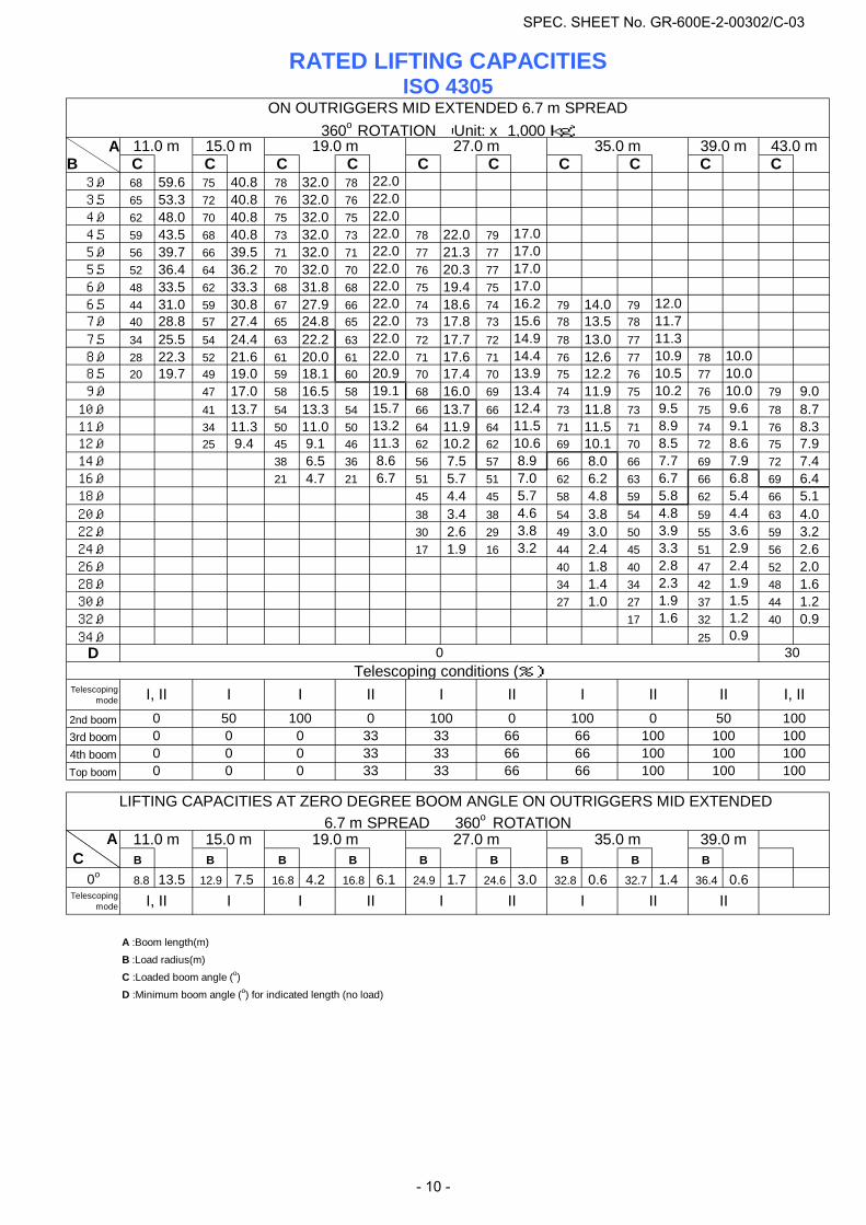
AB C C C C C C C C C C
3.0 68 59.6 75 40.8 78 32.0 78 22.0 3.5 65 53.3 72 40.8 76 32.0 76 22.0 4.0 62 48.0 70 40.8 75 32.0 75 22.0 4.5 59 43.5 68 40.8 73 32.0 73 22.0 78 22.0 79 17.0 5.0 56 39.7 66 39.5 71 32.0 71 22.0 77 21.3 77 17.0 5.5 52 36.4 64 36.2 70 32.0 70 22.0 76 20.3 77 17.0 6.0 48 33.5 62 33.3 68 31.8 68 22.0 75 19.4 75 17.0 6.5 44 31.0 59 30.8 67 27.9 66 22.0 74 18.6 74 16.2 79 14.0 79 12.0 7.0 40 28.8 57 27.4 65 24.8 65 22.0 73 17.8 73 15.6 78 13.5 78 11.7 7.5 34 25.5 54 24.4 63 22.2 63 22.0 72 17.7 72 14.9 78 13.0 77 11.3 8.0 28 22.3 52 21.6 61 20.0 61 22.0 71 17.6 71 14.4 76 12.6 77 10.9 78 10.0 8.5 20 19.7 49 19.0 59 18.1 60 20.9 70 17.4 70 13.9 75 12.2 76 10.5 77 10.0 9.0 47 17.0 58 16.5 58 19.1 68 16.0 69 13.4 74 11.9 75 10.2 76 10.0 79 9.010.0 41 13.7 54 13.3 54 15.7 66 13.7 66 12.4 73 11.8 73 9.5 75 9.6 78 8.711.0 34 11.3 50 11.0 50 13.2 64 11.9 64 11.5 71 11.5 71 8.9 74 9.1 76 8.312.0 25 9.4 45 9.1 46 11.3 62 10.2 62 10.6 69 10.1 70 8.5 72 8.6 75 7.914.0 38 6.5 36 8.6 56 7.5 57 8.9 66 8.0 66 7.7 69 7.9 72 7.416.0 21 4.7 21 6.7 51 5.7 51 7.0 62 6.2 63 6.7 66 6.8 69 6.418.0 45 4.4 45 5.7 58 4.8 59 5.8 62 5.4 66 5.120.0 38 3.4 38 4.6 54 3.8 54 4.8 59 4.4 63 4.022.0 30 2.6 29 3.8 49 3.0 50 3.9 55 3.6 59 3.224.0 17 1.9 16 3.2 44 2.4 45 3.3 51 2.9 56 2.626.0 40 1.8 40 2.8 47 2.4 52 2.028.0 34 1.4 34 2.3 42 1.9 48 1.630.0 27 1.0 27 1.9 37 1.5 44 1.232.0 17 1.6 32 1.2 40 0.934.0 25 0.9
D
Telescopingmode
2nd boom3rd boom4th boomTop boom
A C B B B B B B B B B
0o 8.8 13.5 12.9 7.5 16.8 4.2 16.8 6.1 24.9 1.7 24.6 3.0 32.8 0.6 32.7 1.4 36.4 0.6Telescoping
mode
A :Boom length(m)
B :Load radius(m)
C :Loaded boom angle (o)
D :Minimum boom angle (o) for indicated length (no load)
19.0 m 27.0 m 35.0 m
LIFTING CAPACITIES AT ZERO DEGREE BOOM ANGLE ON OUTRIGGERS MID EXTENDED 6.7 m SPREAD 360o ROTATION
11.0 m 15.0 m 39.0 m
I II I III, II I I II
0100
II
RATED LIFTING CAPACITIES
35.0 m
100 10033
43.0 m
100100
I, II
66 1006666
1000 50
33 330 0 0 1006666
100 100100660 0 0 33
III
39.0 m27.0 m
II
0
I, II ITelescoping conditions (%)
I1000 50 100 0
0 0 0 3333
ISO 4305
IIII
11.0 m 15.0 m
ON OUTRIGGERS MID EXTENDED 6.7 m SPREAD
30
360o ROTATION (Unit: x 1,000 kg)19.0 m
I
SPEC. SHEET No. GR-600E-2-00302/C-03
- 10 -
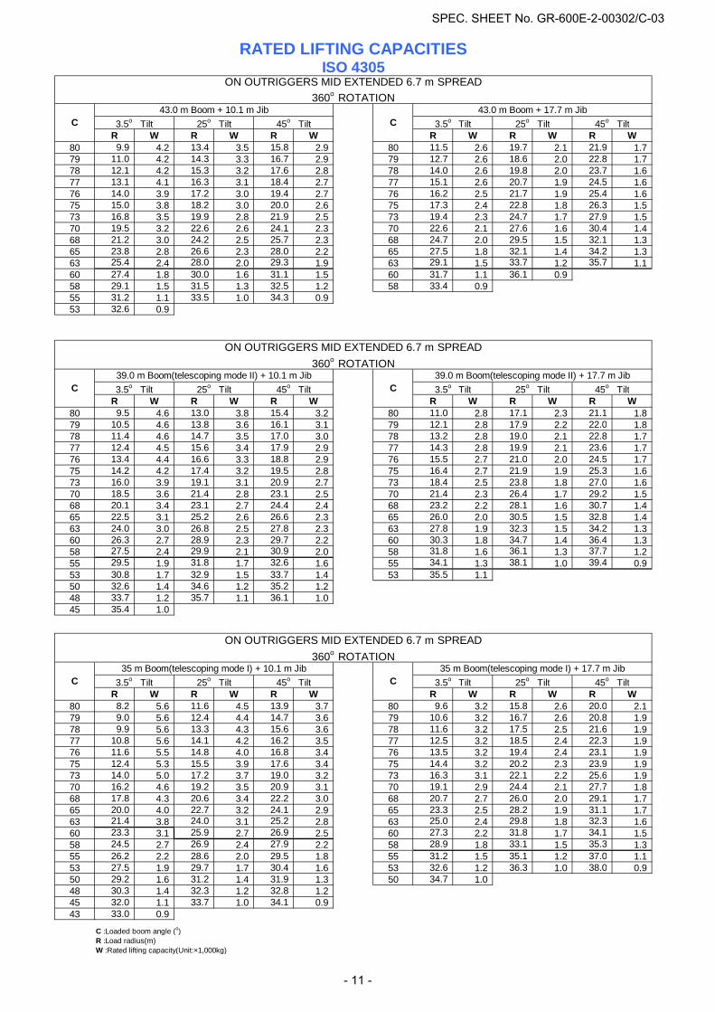
R W R W R W R W R W R W80 9.9 4.2 13.4 3.5 15.8 2.9 80 11.5 2.6 19.7 2.1 21.9 1.779 11.0 4.2 14.3 3.3 16.7 2.9 79 12.7 2.6 18.6 2.0 22.8 1.778 12.1 4.2 15.3 3.2 17.6 2.8 78 14.0 2.6 19.8 2.0 23.7 1.677 13.1 4.1 16.3 3.1 18.4 2.7 77 15.1 2.6 20.7 1.9 24.5 1.676 14.0 3.9 17.2 3.0 19.4 2.7 76 16.2 2.5 21.7 1.9 25.4 1.675 15.0 3.8 18.2 3.0 20.0 2.6 75 17.3 2.4 22.8 1.8 26.3 1.573 16.8 3.5 19.9 2.8 21.9 2.5 73 19.4 2.3 24.7 1.7 27.9 1.570 19.5 3.2 22.6 2.6 24.1 2.3 70 22.6 2.1 27.6 1.6 30.4 1.468 21.2 3.0 24.2 2.5 25.7 2.3 68 24.7 2.0 29.5 1.5 32.1 1.365 23.8 2.8 26.6 2.3 28.0 2.2 65 27.5 1.8 32.1 1.4 34.2 1.363 25.4 2.4 28.0 2.0 29.3 1.9 63 29.1 1.5 33.7 1.2 35.7 1.160 27.4 1.8 30.0 1.6 31.1 1.5 60 31.7 1.1 36.1 0.958 29.1 1.5 31.5 1.3 32.5 1.2 58 33.4 0.955 31.2 1.1 33.5 1.0 34.3 0.953 32.6 0.9
R W R W R W R W R W R W80 9.5 4.6 13.0 3.8 15.4 3.2 80 11.0 2.8 17.1 2.3 21.1 1.879 10.5 4.6 13.8 3.6 16.1 3.1 79 12.1 2.8 17.9 2.2 22.0 1.878 11.4 4.6 14.7 3.5 17.0 3.0 78 13.2 2.8 19.0 2.1 22.8 1.777 12.4 4.5 15.6 3.4 17.9 2.9 77 14.3 2.8 19.9 2.1 23.6 1.776 13.4 4.4 16.6 3.3 18.8 2.9 76 15.5 2.7 21.0 2.0 24.5 1.775 14.2 4.2 17.4 3.2 19.5 2.8 75 16.4 2.7 21.9 1.9 25.3 1.673 16.0 3.9 19.1 3.1 20.9 2.7 73 18.4 2.5 23.8 1.8 27.0 1.670 18.5 3.6 21.4 2.8 23.1 2.5 70 21.4 2.3 26.4 1.7 29.2 1.568 20.1 3.4 23.1 2.7 24.4 2.4 68 23.2 2.2 28.1 1.6 30.7 1.465 22.5 3.1 25.2 2.6 26.6 2.3 65 26.0 2.0 30.5 1.5 32.8 1.463 24.0 3.0 26.8 2.5 27.8 2.3 63 27.8 1.9 32.3 1.5 34.2 1.360 26.3 2.7 28.9 2.3 29.7 2.2 60 30.3 1.8 34.7 1.4 36.4 1.358 27.5 2.4 29.9 2.1 30.9 2.0 58 31.8 1.6 36.1 1.3 37.7 1.255 29.5 1.9 31.8 1.7 32.6 1.6 55 34.1 1.3 38.1 1.0 39.4 0.953 30.8 1.7 32.9 1.5 33.7 1.4 53 35.5 1.150 32.6 1.4 34.6 1.2 35.2 1.248 33.7 1.2 35.7 1.1 36.1 1.045 35.4 1.0
R W R W R W R W R W R W80 8.2 5.6 11.6 4.5 13.9 3.7 80 9.6 3.2 15.8 2.6 20.0 2.179 9.0 5.6 12.4 4.4 14.7 3.6 79 10.6 3.2 16.7 2.6 20.8 1.978 9.9 5.6 13.3 4.3 15.6 3.6 78 11.6 3.2 17.5 2.5 21.6 1.977 10.8 5.6 14.1 4.2 16.2 3.5 77 12.5 3.2 18.5 2.4 22.3 1.976 11.6 5.5 14.8 4.0 16.8 3.4 76 13.5 3.2 19.4 2.4 23.1 1.975 12.4 5.3 15.5 3.9 17.6 3.4 75 14.4 3.2 20.2 2.3 23.9 1.973 14.0 5.0 17.2 3.7 19.0 3.2 73 16.3 3.1 22.1 2.2 25.6 1.970 16.2 4.6 19.2 3.5 20.9 3.1 70 19.1 2.9 24.4 2.1 27.7 1.868 17.8 4.3 20.6 3.4 22.2 3.0 68 20.7 2.7 26.0 2.0 29.1 1.765 20.0 4.0 22.7 3.2 24.1 2.9 65 23.3 2.5 28.2 1.9 31.1 1.763 21.4 3.8 24.0 3.1 25.2 2.8 63 25.0 2.4 29.8 1.8 32.3 1.660 23.3 3.1 25.9 2.7 26.9 2.5 60 27.3 2.2 31.8 1.7 34.1 1.558 24.5 2.7 26.9 2.4 27.9 2.2 58 28.9 1.8 33.1 1.5 35.3 1.355 26.2 2.2 28.6 2.0 29.5 1.8 55 31.2 1.5 35.1 1.2 37.0 1.153 27.5 1.9 29.7 1.7 30.4 1.6 53 32.6 1.2 36.3 1.0 38.0 0.950 29.2 1.6 31.2 1.4 31.9 1.3 50 34.7 1.048 30.3 1.4 32.3 1.2 32.8 1.245 32.0 1.1 33.7 1.0 34.1 0.943 33.0 0.9
C :Loaded boom angle (o)R :Load radius(m)W :Rated lifting capacity(Unit:×1,000kg)
3.5o Tilt 25o Tilt 45o Tilt
3.5o Tilt
3.5o Tilt 25o Tilt 45o Tilt
360o ROTATION
45o Tilt25o Tilt25o Tilt
360o ROTATION
3.5o Tilt 25o Tilt 45o Tilt 3.5o Tilt 25o Tilt 45o Tilt
RATED LIFTING CAPACITIES
C C
43.0 m Boom + 10.1 m Jib 43.0 m Boom + 17.7 m JibC C
ON OUTRIGGERS MID EXTENDED 6.7 m SPREAD360o ROTATION
39.0 m Boom(telescoping mode II) + 17.7 m Jib
ISO 4305
ON OUTRIGGERS MID EXTENDED 6.7 m SPREAD
35 m Boom(telescoping mode I) + 10.1 m Jib 35 m Boom(telescoping mode I) + 17.7 m Jib
C39.0 m Boom(telescoping mode II) + 10.1 m Jib
ON OUTRIGGERS MID EXTENDED 6.7 m SPREAD
C 3.5o Tilt45o Tilt
SPEC. SHEET No. GR-600E-2-00302/C-03
- 11 -
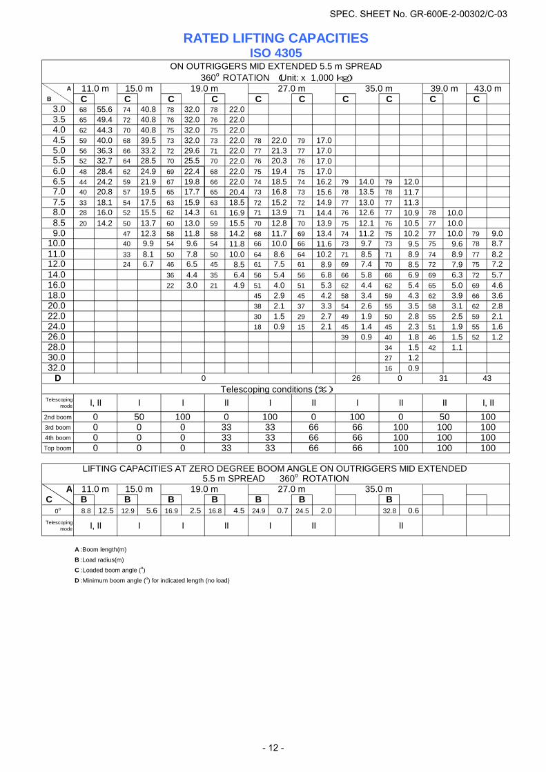
AB C C C C C C C C C C 3.0 68 55.6 74 40.8 78 32.0 78 22.0 3.5 65 49.4 72 40.8 76 32.0 76 22.0 4.0 62 44.3 70 40.8 75 32.0 75 22.0 4.5 59 40.0 68 39.5 73 32.0 73 22.0 78 22.0 79 17.0 5.0 56 36.3 66 33.2 72 29.6 71 22.0 77 21.3 77 17.0 5.5 52 32.7 64 28.5 70 25.5 70 22.0 76 20.3 76 17.0 6.0 48 28.4 62 24.9 69 22.4 68 22.0 75 19.4 75 17.0 6.5 44 24.2 59 21.9 67 19.8 66 22.0 74 18.5 74 16.2 79 14.0 79 12.0 7.0 40 20.8 57 19.5 65 17.7 65 20.4 73 16.8 73 15.6 78 13.5 78 11.7 7.5 33 18.1 54 17.5 63 15.9 63 18.5 72 15.2 72 14.9 77 13.0 77 11.3 8.0 28 16.0 52 15.5 62 14.3 61 16.9 71 13.9 71 14.4 76 12.6 77 10.9 78 10.0 8.5 20 14.2 50 13.7 60 13.0 59 15.5 70 12.8 70 13.9 75 12.1 76 10.5 77 10.0 9.0 47 12.3 58 11.8 58 14.2 68 11.7 69 13.4 74 11.2 75 10.2 77 10.0 79 9.0
10.0 40 9.9 54 9.6 54 11.8 66 10.0 66 11.6 73 9.7 73 9.5 75 9.6 78 8.711.0 33 8.1 50 7.8 50 10.0 64 8.6 64 10.2 71 8.5 71 8.9 74 8.9 77 8.212.0 24 6.7 46 6.5 45 8.5 61 7.5 61 8.9 69 7.4 70 8.5 72 7.9 75 7.214.0 36 4.4 35 6.4 56 5.4 56 6.8 66 5.8 66 6.9 69 6.3 72 5.716.0 22 3.0 21 4.9 51 4.0 51 5.3 62 4.4 62 5.4 65 5.0 69 4.618.0 45 2.9 45 4.2 58 3.4 59 4.3 62 3.9 66 3.620.0 38 2.1 37 3.3 54 2.6 55 3.5 58 3.1 62 2.822.0 30 1.5 29 2.7 49 1.9 50 2.8 55 2.5 59 2.124.0 18 0.9 15 2.1 45 1.4 45 2.3 51 1.9 55 1.626.0 39 0.9 40 1.8 46 1.5 52 1.228.0 34 1.5 42 1.130.0 27 1.232.0 16 0.9
D
Telescopingmode
2nd boom
3rd boom
4th boom
Top boom
A C B B B B B B B
0o 8.8 12.5 12.9 5.6 16.9 2.5 16.8 4.5 24.9 0.7 24.5 2.0 32.8 0.6Telescoping
mode
A :Boom length(m)
B :Load radius(m)
C :Loaded boom angle (o)
D :Minimum boom angle (o) for indicated length (no load)
LIFTING CAPACITIES AT ZERO DEGREE BOOM ANGLE ON OUTRIGGERS MID EXTENDED 5.5 m SPREAD 360o ROTATION
11.0 m 15.0 m 19.0 m 27.0 m 35.0 m
I II III, II I I II
RATED LIFTING CAPACITIES
066
ON OUTRIGGERS MID EXTENDED 5.5 m SPREAD360o ROTATION (Unit: x 1,000 kg)
0II
33 100
0
100
II
33100
I I, IIII
10010050
I, II I I
0 00 0 00 50
33 10066660 0 0 1000
100 0III
100
10033 3333 100
11.0 m 15.0 m 19.0 m
Telescoping conditions (%)
433126 0
ISO 4305
66
1006666
35.0 m 39.0 m 43.0 m
100
27.0 m
SPEC. SHEET No. GR-600E-2-00302/C-03
- 12 -
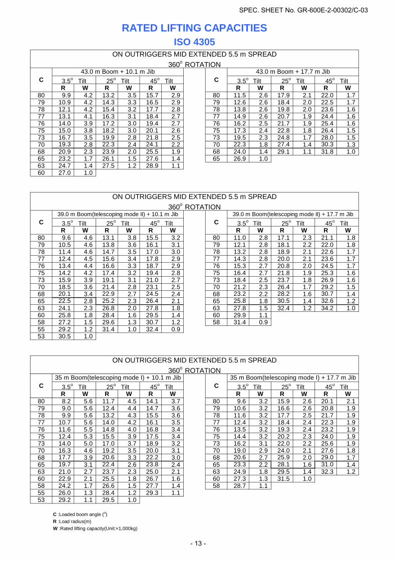
R W R W R W R W R W R W80 9.9 4.2 13.2 3.5 15.7 2.9 80 11.5 2.6 17.9 2.1 22.0 1.779 10.9 4.2 14.3 3.3 16.5 2.9 79 12.6 2.6 18.4 2.0 22.5 1.778 12.1 4.2 15.4 3.2 17.7 2.8 78 13.8 2.6 19.8 2.0 23.6 1.677 13.1 4.1 16.3 3.1 18.4 2.7 77 14.9 2.6 20.7 1.9 24.4 1.676 14.0 3.9 17.2 3.0 19.4 2.7 76 16.2 2.5 21.7 1.9 25.4 1.675 15.0 3.8 18.2 3.0 20.1 2.6 75 17.3 2.4 22.8 1.8 26.4 1.573 16.7 3.5 19.9 2.8 21.8 2.5 73 19.5 2.3 24.8 1.7 28.0 1.570 19.3 2.8 22.3 2.4 24.1 2.2 70 22.3 1.8 27.4 1.4 30.3 1.368 20.9 2.3 23.9 2.0 25.5 1.9 68 24.0 1.4 29.1 1.1 31.8 1.065 23.2 1.7 26.1 1.5 27.6 1.4 65 26.9 1.063 24.7 1.4 27.5 1.2 28.9 1.160 27.0 1.0
R W R W R W R W R W R W80 9.6 4.6 13.1 3.8 15.5 3.2 80 11.0 2.8 17.1 2.3 21.1 1.879 10.5 4.6 13.8 3.6 16.1 3.1 79 12.1 2.8 18.1 2.2 22.0 1.878 11.4 4.6 14.7 3.5 17.0 3.0 78 13.2 2.8 18.9 2.1 22.6 1.777 12.4 4.5 15.6 3.4 17.8 2.9 77 14.3 2.8 20.0 2.1 23.6 1.776 13.4 4.4 16.6 3.3 18.7 2.9 76 15.3 2.7 20.8 2.0 24.5 1.775 14.2 4.2 17.4 3.2 19.4 2.8 75 16.4 2.7 21.8 1.9 25.3 1.673 15.9 3.9 19.1 3.1 21.0 2.7 73 18.4 2.5 23.7 1.8 26.9 1.670 18.5 3.6 21.4 2.8 23.1 2.5 70 21.2 2.3 26.4 1.7 29.2 1.568 20.1 3.4 22.9 2.7 24.5 2.4 68 23.2 2.2 28.2 1.6 30.7 1.465 22.5 2.8 25.2 2.3 26.4 2.1 65 25.8 1.8 30.5 1.4 32.6 1.263 24.1 2.3 26.8 2.0 27.8 1.8 63 27.8 1.5 32.4 1.2 34.2 1.060 25.8 1.8 28.4 1.6 29.5 1.4 60 29.9 1.158 27.2 1.5 29.6 1.3 30.7 1.2 58 31.4 0.955 29.2 1.2 31.4 1.0 32.4 0.953 30.5 1.0
R W R W R W R W R W R W80 8.2 5.6 11.7 4.5 14.1 3.7 80 9.6 3.2 15.9 2.6 20.1 2.179 9.0 5.6 12.4 4.4 14.7 3.6 79 10.6 3.2 16.6 2.6 20.8 1.978 9.9 5.6 13.2 4.3 15.5 3.6 78 11.6 3.2 17.7 2.5 21.7 1.977 10.7 5.6 14.0 4.2 16.1 3.5 77 12.4 3.2 18.4 2.4 22.3 1.976 11.6 5.5 14.8 4.0 16.8 3.4 76 13.5 3.2 19.3 2.4 23.2 1.975 12.4 5.3 15.5 3.9 17.5 3.4 75 14.4 3.2 20.2 2.3 24.0 1.973 14.0 5.0 17.0 3.7 18.9 3.2 73 16.2 3.1 22.0 2.2 25.6 1.970 16.3 4.6 19.2 3.5 20.0 3.1 70 19.0 2.9 24.0 2.1 27.6 1.868 17.7 3.9 20.6 3.3 22.2 3.0 68 20.6 2.7 25.9 2.0 29.0 1.765 19.7 3.1 22.4 2.6 23.8 2.4 65 23.3 2.2 28.1 1.6 31.0 1.463 21.0 2.7 23.7 2.3 25.0 2.1 63 24.9 1.8 29.5 1.4 32.3 1.260 22.9 2.1 25.5 1.8 26.7 1.6 60 27.3 1.3 31.5 1.058 24.2 1.7 26.6 1.5 27.7 1.4 58 28.7 1.155 26.0 1.3 28.4 1.2 29.3 1.153 29.2 1.1 29.5 1.0
C :Loaded boom angle (o)R :Load radius(m)W :Rated lifting capacity(Unit:×1,000kg)
ISO 4305
45o Tilt25o Tilt
ON OUTRIGGERS MID EXTENDED 5.5 m SPREAD
25o Tilt 45o Tilt
45o Tilt
3.5o Tilt 25o Tilt 45o Tilt 3.5o Tilt
3.5o Tilt 25o Tilt 45o Tilt
360o ROTATION
3.5o Tilt 25o Tilt 45o Tilt
ON OUTRIGGERS MID EXTENDED 5.5 m SPREAD360o ROTATION
ON OUTRIGGERS MID EXTENDED 5.5 m SPREAD
C39.0 m Boom(telescoping mode II) + 10.1 m Jib 39.0 m Boom(telescoping mode II) + 17.7 m Jib
3.5o Tilt3.5o Tilt 25o Tilt
360o ROTATION
RATED LIFTING CAPACITIES
C C
43.0 m Boom + 10.1 m Jib 43.0 m Boom + 17.7 m JibC C
C
35 m Boom(telescoping mode I) + 10.1 m Jib 35 m Boom(telescoping mode I) + 17.7 m Jib
SPEC. SHEET No. GR-600E-2-00302/C-03
- 13 -

AB C C C C C C C C C C
3.0 68 26.3 74 22.3 78 19.3 78 22.0 3.5 65 21.4 72 18.3 76 16.0 76 18.7 4.0 62 17.8 70 15.4 75 13.5 75 16.1 4.5 59 15.0 68 13.1 73 11.5 73 14.0 78 10.9 78 12.5 5.0 55 12.9 66 11.3 72 9.9 71 12.3 77 9.5 77 11.1 5.5 52 11.2 64 9.8 70 8.6 69 10.9 76 8.4 76 10.0 6.0 48 9.8 61 8.5 68 7.5 68 9.8 75 7.5 75 9.0 6.5 44 8.6 59 7.4 67 6.6 66 8.8 74 6.7 74 8.2 78 6.4 79 7.5 7.0 40 7.6 57 6.5 65 5.7 64 7.9 73 6.0 72 7.4 77 5.8 78 6.9 7.5 34 6.6 55 5.7 63 5.0 63 7.1 71 5.3 71 6.8 76 5.2 77 6.3 8.0 28 5.7 52 5.0 61 4.3 61 6.5 70 4.8 70 6.2 75 4.7 76 5.8 77 5.1 8.5 19 5.0 49 4.4 59 3.8 59 5.9 69 4.3 69 5.7 75 4.3 75 5.4 77 4.7 9.0 47 3.9 58 3.3 57 5.3 68 3.8 68 5.3 74 3.9 74 5.0 76 4.3 78 3.810.0 41 2.9 54 2.4 53 4.4 66 3.1 65 4.5 72 3.2 72 4.3 74 3.7 76 3.211.0 33 2.2 49 1.7 49 3.7 63 2.4 63 3.8 70 2.6 71 3.7 73 3.1 75 2.612.0 25 1.5 45 1.1 45 3.1 61 1.9 60 3.2 69 2.1 69 3.2 71 2.6 73 2.214.0 35 2.0 56 1.0 55 2.3 65 1.3 65 2.3 68 1.8 70 1.416.0 20 1.3 49 1.6 62 1.7 64 1.218.0 38 1.1 58 1.2
D
Telescopingmode
2nd boom
3rd boom
4th boom
Top boom
A C B B B
0o8.7 4.5 12.9 0.9 16.7 1.1
Telescopingmode
A :Boom length(m)
B :Load radius(m)
C :Loaded boom angle (o)
D :Minimum boom angle (o) for indicated length (no load)
I, II I II
15.0 m 19.0 m
ISO 4305
49 57 64
27.0 m
ON OUTRIGGERS MIN EXTENDED 2.7 m SPREAD360o ROTATION (Unit: x 1,000 kg)
100 100
RATED LIFTING CAPACITIES
21 44 27
35.0 m 39.0 m 43.0 m11.0 m 15.0 m 19.0 m
10066 10010066 100
0 0 0 33330 0 0 33
III II I, IIIII, II I I II I100
0 0 0 33 33 10066 100 1000
570 0
01000 50 100
Telescoping conditions (%)
LIFTING CAPACITIES AT ZERO DEGREE BOOM ANGLE ON OUTRIGGERS MIN EXTENDED 2.7 m SPREAD 360o ROTATION
11.0 m
0 10066
33 6666
50
SPEC. SHEET No. GR-600E-2-00302/C-03
- 14 -
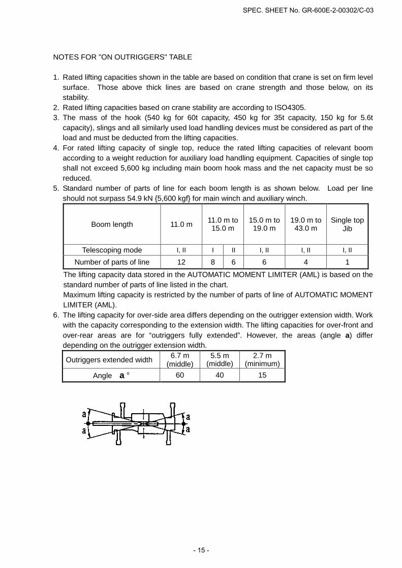
NOTES FOR "ON OUTRIGGERS" TABLE
1. Rated lifting capacities shown in the table are based on condition that crane is set on firm level surface. Those above thick lines are based on crane strength and those below, on its stability.
2. Rated lifting capacities based on crane stability are according to ISO4305. 3. The mass of the hook (540 kg for 60t capacity, 450 kg for 35t capacity, 150 kg for 5.6t
capacity), slings and all similarly used load handling devices must be considered as part of the load and must be deducted from the lifting capacities.
4. For rated lifting capacity of single top, reduce the rated lifting capacities of relevant boom according to a weight reduction for auxiliary load handling equipment. Capacities of single top shall not exceed 5,600 kg including main boom hook mass and the net capacity must be so reduced.
5. Standard number of parts of line for each boom length is as shown below. Load per line should not surpass 54.9 kN {5,600 kgf} for main winch and auxiliary winch.
Boom length 11.0 m 11.0 m to 15.0 m
15.0 m to 19.0 m
19.0 m to 43.0 m
Single top Jib
Telescoping mode I, II I II I, II I, II I, II Number of parts of line 12 8 6 6 4 1
The lifting capacity data stored in the AUTOMATIC MOMENT LIMITER (AML) is based on the standard number of parts of line listed in the chart. Maximum lifting capacity is restricted by the number of parts of line of AUTOMATIC MOMENT LIMITER (AML).
6. The lifting capacity for over-side area differs depending on the outrigger extension width. Work with the capacity corresponding to the extension width. The lifting capacities for over-front and over-rear areas are for “outriggers fully extended”. However, the areas (angle a) differ depending on the outrigger extension width.
Outriggers extended width 6.7 m (middle)
5.5 m (middle)
2.7 m (minimum)
Angle a o 60 40 15
SPEC. SHEET No. GR-600E-2-00302/C-03
- 15 -
A
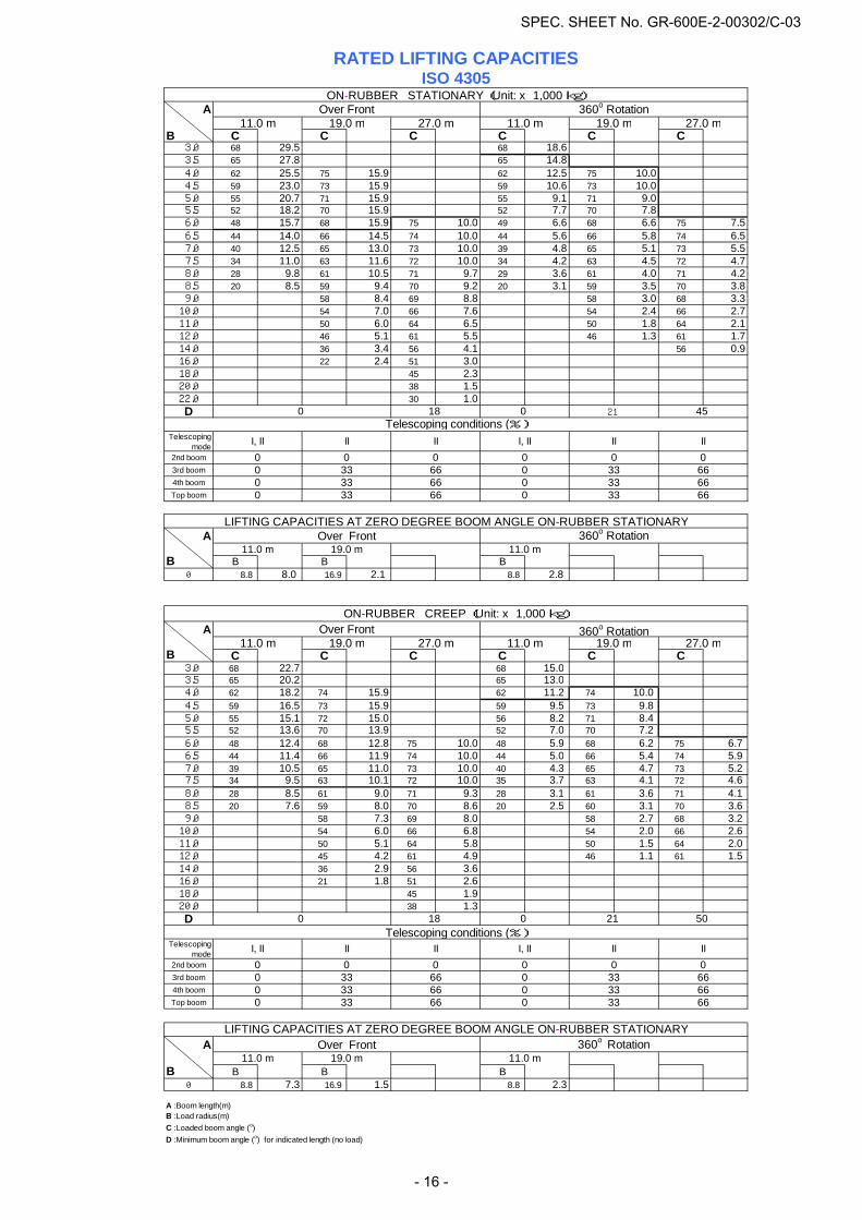
B C C C C C C 3.0 68 29.5 68 18.6 3.5 65 27.8 65 14.8 4.0 62 25.5 75 15.9 62 12.5 75 10.0 4.5 59 23.0 73 15.9 59 10.6 73 10.0 5.0 55 20.7 71 15.9 55 9.1 71 9.0 5.5 52 18.2 70 15.9 52 7.7 70 7.8 6.0 48 15.7 68 15.9 75 10.0 49 6.6 68 6.6 75 7.5 6.5 44 14.0 66 14.5 74 10.0 44 5.6 66 5.8 74 6.5 7.0 40 12.5 65 13.0 73 10.0 39 4.8 65 5.1 73 5.5 7.5 34 11.0 63 11.6 72 10.0 34 4.2 63 4.5 72 4.7 8.0 28 9.8 61 10.5 71 9.7 29 3.6 61 4.0 71 4.2 8.5 20 8.5 59 9.4 70 9.2 20 3.1 59 3.5 70 3.8 9.0 58 8.4 69 8.8 58 3.0 68 3.310.0 54 7.0 66 7.6 54 2.4 66 2.711.0 50 6.0 64 6.5 50 1.8 64 2.112.0 46 5.1 61 5.5 46 1.3 61 1.714.0 36 3.4 56 4.1 56 0.916.0 22 2.4 51 3.018.0 45 2.320.0 38 1.522.0 30 1.0D
Telescopingmode
2nd boom3rd boom4th boomTop boom
A
B B B B0 8.8 8.0 16.9 2.1 8.8 2.8
A
B C C C C C C 3.0 68 22.7 68 15.0 3.5 65 20.2 65 13.0 4.0 62 18.2 74 15.9 62 11.2 74 10.0 4.5 59 16.5 73 15.9 59 9.5 73 9.8 5.0 55 15.1 72 15.0 56 8.2 71 8.4 5.5 52 13.6 70 13.9 52 7.0 70 7.2 6.0 48 12.4 68 12.8 75 10.0 48 5.9 68 6.2 75 6.7 6.5 44 11.4 66 11.9 74 10.0 44 5.0 66 5.4 74 5.9 7.0 39 10.5 65 11.0 73 10.0 40 4.3 65 4.7 73 5.2 7.5 34 9.5 63 10.1 72 10.0 35 3.7 63 4.1 72 4.6 8.0 28 8.5 61 9.0 71 9.3 28 3.1 61 3.6 71 4.1 8.5 20 7.6 59 8.0 70 8.6 20 2.5 60 3.1 70 3.6 9.0 58 7.3 69 8.0 58 2.7 68 3.210.0 54 6.0 66 6.8 54 2.0 66 2.611.0 50 5.1 64 5.8 50 1.5 64 2.012.0 45 4.2 61 4.9 46 1.1 61 1.514.0 36 2.9 56 3.616.0 21 1.8 51 2.618.0 45 1.920.0 38 1.3D
Telescopingmode
2nd boom3rd boom4th boomTop boom
A
B B B B0 8.8 7.3 16.9 1.5 8.8 2.3
A :Boom length(m)B :Load radius(m)C :Loaded boom angle (o)D :Minimum boom angle (o) for indicated length (no load)
0
33 66
Telescoping conditions (%)
33 660 33 66
II
11.0 m
0 0
II0 0
0 21 50
I, II
0
II
19.0 m
Telescoping conditions (%)
360o Rotation11.0 m 19.0 m 27.0 m19.0 m 27.0 m
Over FrontON-RUBBER CREEP (Unit: x 1,000 kg)
11.0 m
I, II
45
33
19.0 m 27.0 m
II
27.0 m
ON-RUBBER STATIONARY (Unit: x 1,000 kg)
RATED LIFTING CAPACITIES
0 33 66
11.0 mOver Front 360o Rotation
0
18
I, II
ISO 4305
LIFTING CAPACITIES AT ZERO DEGREE BOOM ANGLE ON-RUBBER STATIONARYOver Front 360o Rotation
0 33 66
II0 0
II0
66
11.0 m 19.0 m 11.0 m
0 33 660
0 33 660 33 66
33 66660 33
I, II II II
6633
11.0 m 19.0 m 11.0 m
00 0 00
0
0 21
LIFTING CAPACITIES AT ZERO DEGREE BOOM ANGLE ON-RUBBER STATIONARYOver Front 360o Rotation
0
0
18
SPEC. SHEET No. GR-600E-2-00302/C-03
- 16 -
NOTES FOR "ON-RUBBER" TABLES
1. Rated lifting capacities shown in the table are based on condition that crane is set on firm
level surface, with suspension lock applied. Those above thick lines are based on tire capacity and those below, on crane stability. They are based on actual load radius increased by tire deformation and boom deflection.
2. Rated lifting capacities based on crane stability are according to ISO4305. 3. The mass of the hook (540 kg for 60t capacity, 450 kg for 35t capacity, 150 kg for 5.6t
capacity), slings and all similarly used load handling devices must be considered as part of the load and must be deducted from the lifting capacities.
4. For rated lifting capacity of single top, reduce the rated lifting capacities of relevant boom according to weight reductions for auxiliary load handling equipment. Capacities of single top shall not exceed 5,600 kg including main hook.
5. On-rubber lifting with "jib" is not permitted. Maximum permissible boom length is 27.0 m. 6. CREEP is motion for crane not to travel more than 60 m in any 30 minute period and to
travel at the speed of less than 1.6 km/h. 7. During "CREEP" duties travel slowly and keep the lifting load as close to the ground as
possible, and especially avoid any abrupt steering, accelerating or braking. 8. Do not operate the crane while carrying the load. 9. Tires should be inflated to their correct air pressure.
Tires Air pressure 29.5-25 22PR 420 kPa 29.5-25 28PR 450 kPa
10. For CREEP operation, choose the drive mode and proper gear according to the road or working condition.
11. Standard number of parts of line for on-rubber operation should be according to the following table. Load per line should not surpass 54.9 kN {5,600 kgf} for main winch and auxiliary winch.
Boom length 11.0 m 11.0 m to 27.0 m Single top
Telescoping mode I, II II I, II Number of parts of line 6 4 1
The lifting capacity data stored in the AUTOMATIC MOMENT LIMITER (AML) is based on the standard number of parts of line listed in the chart. Maximum lifting capacity is restricted by the number of parts of line of AUTOMATIC MOMENT LIMITER (AML).
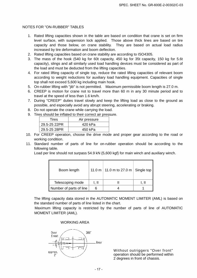
WORKING AREA
Without outr iggers "Over f ront" operation should be performed within 2 degrees in front of chassis.
SPEC. SHEET No. GR-600E-2-00302/C-03
- 17 -

WORKING RANGE CHART
SPEC. SHEET No. GR-600E-2-00302/C-03
- 18 -
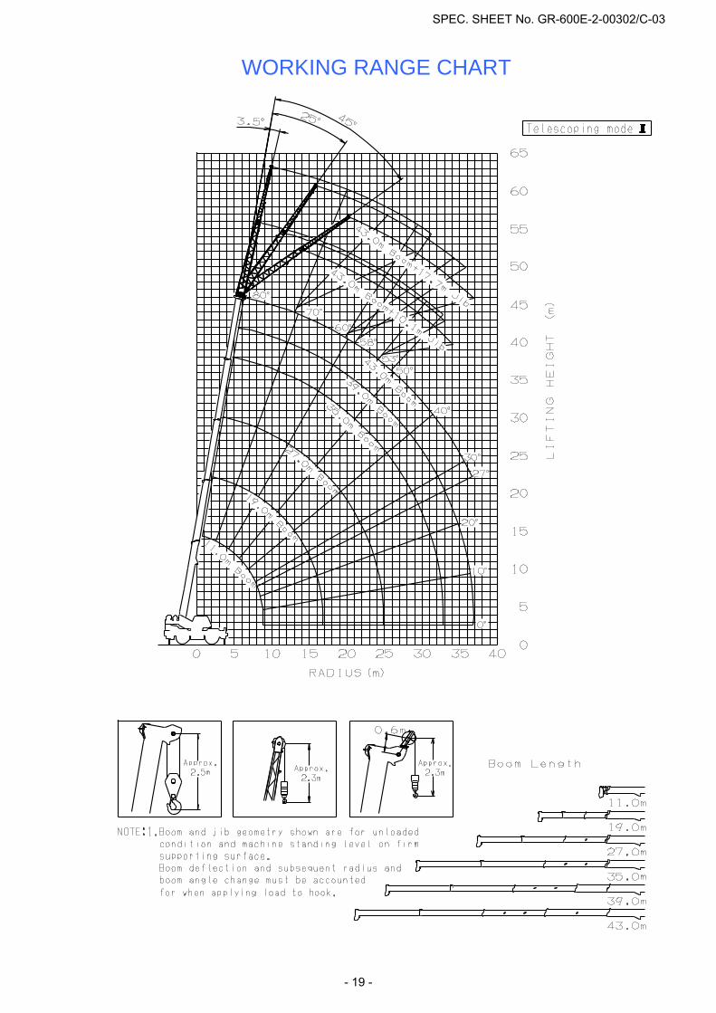
WORKING RANGE CHART
SPEC. SHEET No. GR-600E-2-00302/C-03
- 19 -
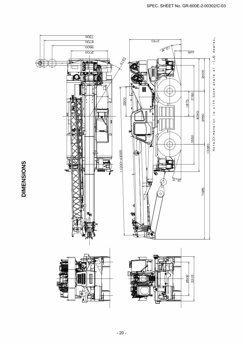
DIM
ENSI
ON
S
SPEC. SHEET No. GR-600E-2-00302/C-03
- 20 -
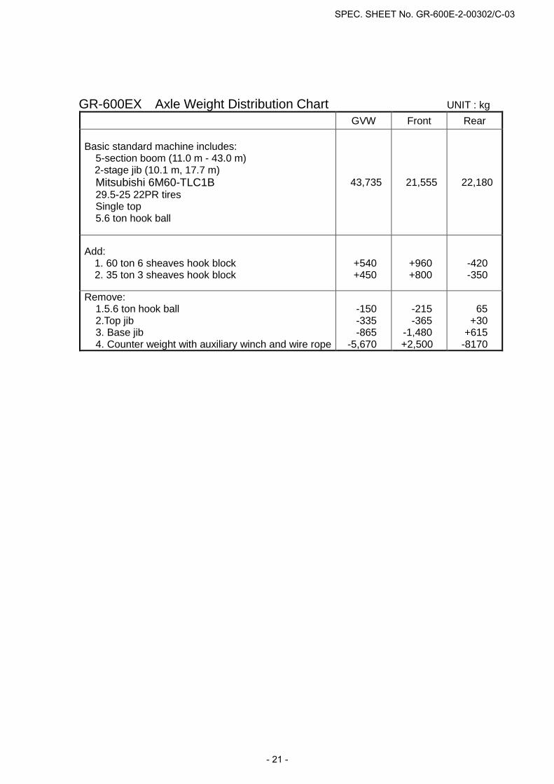
GR-600EX Axle Weight Distribution Chart UNIT : kg GVW Front Rear
Basic standard machine includes: 5-section boom (11.0 m - 43.0 m)
2-stage jib (10.1 m, 17.7 m) Mitsubishi 6M60-TLC1B
29.5-25 22PR tires Single top 5.6 ton hook ball
43,735 21,555 22,180
Add: 1. 60 ton 6 sheaves hook block 2. 35 ton 3 sheaves hook block
+540 +450
+960 +800
-420 -350
Remove: 1.5.6 ton hook ball 2.Top jib 3. Base jib 4. Counter weight with auxiliary winch and wire rope
-150
-335 -865
-5,670
-215 -365
-1,480 +2,500
65
+30 +615
-8170
SPEC. SHEET No. GR-600E-2-00302/C-03
- 21 -