Embed Size (px)
Citation preview

REHABILITATION MANUAL 13
TACTILE GROUND SURFACEINDICATORS
FOR BLIND PERSONS
NationalRehabilitation Center fbr Persons with Disabilities
Japan Federation of the Blind
NATIONAL REHABILITATION CENTER
FOR THE DISABLED
JAPAN
(WHO COLLABORATING CENTRE)
December,2003
The NationalRehabilitation Center fbr Persons with Disabilities was designated as
the WHO Collaborating Centerfor Disability Prevention andRehabilitationin1995.
Ter)nS Of Ref6rences are:
1 Toundertake research anddevelopmentofdisabilitypreventionandrehabilitation
technology,and,tO disseminateinformation on the use ofsuch technology through
education and trainlng OfWHO fbllows and other professionalstaff.
2 Toundertakeassessmentofexistingtechnologywhichfacilitatestheindependence
Ofpeople disabilities,and to disseminate suchinfbrmation on technology through
education and training.
3 To undertake studies of community-based rehabilitation,Prlmary health care,
and other socialsupport mechanisms fbr people with disabilities.
4 To undertake research and development10f new equlPment and devicesin
rehabilitation and dailylif60fpeople with di$abilities.
5 To develop and prepare manuals for education and training of rehabilitation
pro鮎ssionals.
6 To support organization of-COnfbrences and/or seminars onrehabilitation ofpeople
with di$abilities.
NationalRehabilitation Centerfor Persons with Disabilities
WHO Collaborating Centre fbrDisability Prevention and Rehabilitation
Rehabilitation Manual 13
Tactile Ground SurfaceIndicators放〉r Blind Persons
December26,2003▲
Editor:Shigeru YAMAUCHI,YasutaknYAMAUCHI
伝)NationalRehabilitation Center fbr Persons with Disabilities
Tokutaro SATO,M.D.,Ph.D.,President
4-1Namiki,Tokorozawa City,Saitama Prefecture359・8555,Japan
Tel.81-4-2995・3100
Fax.81・4-2995・3102
E-mail:whoclbc@rehab.go.jp
PREmCE
This manualis a compilation ofinformation on tactile groundindicatorsfor
blind persons(hereinafter refbrred to as-tactile groundindicatorr).Thefo1lowing
three factors are key to providing effective tactile ground indicators to visually
impaired persons:standardizedfeaturesfor theindicators and requirementsfor
installation,nO COmmunication barriers between theinstaller and the user,and
establishment ofthe use of theindicators and trainlng methods.The aim ofthis
Publicationis to compileinbrmation that addresses these key mattersinto a
manualrelevant to the present situationinJapan and to promote the social
participation ofpersons with visualimpalrmentin the Asia-Pacific reglOn.
Tactile groundindicators wereinvented by Mr.SeiichiMiyake,from Okayama.
They wereinstalled fbr the丘rst time anywhere onthe Nationalroad near the OkayamaSchoolfbrtheBlindinMarch1967,fbllowedbyinstallationinKyotoand
Osaka.They wereintroducedinto Tokyoin thefo1lowing year and then spread
gradually throughout the country.During the process,the application of tactile
groundindicators widenedin scope toinclude railway station platformsin addition
to pedestrianfootways.This was partlyin response to presslng needfor tactile
groundindicatorinstallationin suchlocations to prevent persons with visual
impalrment from falling offthe railway platforms.
The numericaltargets for theinstallation of tactile groundindicators are
Currentlylistedinthe Action Planfor Persons with Disabilities.The Action Plan
for Persons with Disabilities released at the end of2002contains thefo1lowing
projects.一Renovation ofexisting government facilities under the jurisdiction ofthe
Ministry of Land,Infrastructure and Transport where fYont office operations are
COnducted.Such renovationsinclude theinstallation of handrails,ramPS,taCtile
groundindicators,tOilets fbr persons withdisabilities,autOmatic doors,elevators
(totalfl00r area Of morethanl,000m2),and this projectis to be completed by
fiscalyear2010.‥Promotion of the elimination of steps,improvement of tactile
groundindicators,theinsta11ationoftoiletsforpersons with disabilitiesinbasically
allfacilitiesincluding existing railway stations、bus terminals,and passenger-Ship
Or airterminals wherethe average numberofusers per dayis5,0000rmOre.This
projectis expected to be complete by fiscalyear2010.▼
According toWhite Paper on Persons with Disabilitiesissuedin FY2002,the
adoption rate of tactile groundindicatorsinJRrs rai1way・related facilities with
average dailypassenger traffic ofmore than5,000was99.0%:(936stations out of
945stations)attheendofFY2001.Theratefor15privaterailwaycompanieswas
95.9%(957stationsoutof998stations),andfortheTeitoRapidTransitAuthority
and the public subways waslOO%(al1548stations surveyed).

Thereis no doubt that the tremendous demand from the visuallyimpaired
played a maJOr rOleinbringlng about such a high rate ofadoption,but the role of
the governmentin standardization was also slgnificant.Standardization of tactile
groundindicators started with the-Guideline fbr Tactile Ground SurfaceIndicators
for Blind Persons’issued by the then Ministry of Constructionin September1985、
fo1lowed by the enactment of the ‖JIS T 9251:20001Tactile Ground Surface
Indicatorfor Blind Persons‖in September2001.
Chapterlof this publicationis mainly based on thelJIS T9251:2001’and Chapter 2is based on the guidelines set by the then Ministry of Construction.
Chapter3is based on the practicaltrainingprovided by this centerin the area of
Walking trainlng for visua11yimpaired persons as part of the courses of
independentliving skills training at our Training Center and rehabilitationfor
PerSOnS With visualdisabilit・ies at our College.
Ⅰ’dlike to express my specialthanks toJapanAssociation fbr the Blind fbr
COntribution ofthis manualin co11aboration with staffs ofour Train1ng Center.
S.YAMAUCHI
EDITOR
Shigeru YAMAUCHI,Yasutaka YAMAUCHI
NationalRehabilitation Centerfor Personswith Disabilities
CONTRIBUTORS
Hidenobu GOTO
NationalRehabilitation Centerfor Persons with Disabilities
Akio WATANABE
NationalRehabilitation Centerfor Personswith Disabilities
Y両imO NationalRehabilitation Centerfor Persons with Disabilities
Akira KOBAYASHI
NationalRehabilitation Centerfor Personswith Disabilities
YasufumiMIYOSHI
NationalRehabilitation Centerfor Personswith Disabilities
Masahiro WATLANABE
NationalRehabilitation Centerfor Personswith Disabilities
Katsuko SUZUKI
NationalRehabilitation Centerfor Persons with二Disabilities
Kazutoshi KAN
Japan Federation of the Blind
ILLUSTRATOR
JuIカiMORI
CONTENTS
Preface
Contributors
Chapterl.
Shape ofTactile GroundIndicators
l.Principles upon which the Shape ofTactile GroundIndicators are Based
2.Shape ofTactile GroundIndicators Based onJIS T9251
1)Dot tiles
(1)Shape ofdotbumps on a dot tile
(2)Size of a Dot Tile
(3)para11elArrangement ofa Dot Tile
2)Bar Tiles
(1)Shape ofBars on a Bar Tile
(2)Size of a Bar Tile
(3)Depth ofGrooves andTolerance
3.Shapes notin Compliance withJIS T9251
1)Dome-Shaped Dot Tiles
2)Oval-Shaped Bar Tiles
3)ZigzagAnrangement
4.Other Requirements
l 1 2 2 2 3 3 4 4 1a 6 6 7 7 7 8
Chapter2.
Method ofInstallation of Tactile GroundIndicators
l.Installation Principles ofTactile GroundIndicators
l)Installation where directionalindicationis necessary
2)Tactile groundindicators sha11beinstalled to alert the user to a possible
danger or toindicate access to the facilities ofthe destination.
2.Notes onInsta11ation of Tactile GroundIndicators
l)Simplicity and Sequence
2)Contrastto theAdjoining Surface(tactileandvisualsenses)
3)Separate use ofdot tiles andbar tiles
(1)Installation of dot tiles
(2)Installation ofbar tiles
(3)Combined dot tiles and bar tiles
(4)Width oftiles to beinstalled
(5)Installationinthe fbrm ofa square without alteration
9 9 9
9
10
10
11
11
11
12
12
12
14
14
15
15
15
15
17
18
19
19
20
21
21
21
22
22
22
23
23
(6)PR activity ofinstalled routes
3.Practicalexamples ofinstallation
l)Roads
(1)Footways
(2)Pedestrian cros$ings
(3)Curb ramps
(4)Approachestoundergroundcrossings
(5)Medians
(6)Bus stops
(7)CurveS/deflections andturningpoints
2)Public Transport
(1)Railway platfbrms
(2)Ticket gates
(3)Concourses
3)Public facilities
(1)Access to facilities
(2)Stairways
(3)Elevators
Chapter3.
MobilitywithTactileGroundSurfaceIndicators
l.Basic travelski11sforpersonswithvisualimpalrment
l)Protection and trailing
(1)Protection
(2)Trailir唱
2)Basic cane techniques
(1)White cane
(2)Basic cane techniques
A.Touch teclmique
a)Basic grip
b)Starting position
c)Cane controltechnique
B.Constant contact
C.Shorelining technique
D.I.D.Technique
3)Movingaroundwithresidualvision
A.Monoculars
B.Absorptivelenses
24
24
24
24
25
26
26
26
26
26
27
27
28
28
29
29
30
31
l 1 2 3 5-∂ 6 7 8 9 9 0 1 1 1 1 3 3 4 4 4 5 3 3 3 3 3 3 3 3 3 3 3 4 4 4 4 4 4 4 4 4 4 4
2.Practicalexamples ofwalking usingtactile groundindicators
l)Stairs
(1)Finding stairs and ascending/descending
(2)Finding thelast step orlanding
2)Elevators
(1)How to nnd the elevator button
3)Finding a facility entrance
4)Traveling throughlobbies
5)Travelonfootway
6)Negotiating a turning point
7)Finding crossing points
8)Crossing pedestrian crossings
9)Findingbus stops
lO)Access to public transport
(1)platforms
A.Boarding trains
B.After getting offtrains
C.Points to keepin mind whentraveling
(2)Ticket gates
A.Travelto ticket gates
B.Travelた・Om ticket gates to platforms
(3)Concourse
References
Chapterl.
Shape ofTactile GroundIndicators
l.Principles upon which the Shape ofTactile GroundIndicators are Based
It has been more than35years since thefirst tactile groundindicator was
installed.CurrentlylnJapan,a COnCrete tile about60mm thickis genera11y set
into an asphalt pedestrian roadfor outdoor use,and a thin reinforced plastic tile
about5mmthickis gluedontoanoorforindooruse.Thecolorisgenerallyyellow
asthis hueis morevisible to persons withlowvision.Thisis because yellow
contrasts sharply against most background surfaces.
Atfirst,taCtile groundindicators were concrete tiles with48dome-Shaped dots
arrangedin para11el:however,Since theirintroduction,Various types ofindicators
have been developed,including bar tiles.tiles with oval-Shaped dots and dot tiles
arrangedin a zlgZag COn負guration.ThusinJapan、Various types oftactile ground
indicators arenowbeingused.InLbrmationtransmittedbytactile groundindicators
to visuallyimpaired people can be summarized asfo1lows.
・To alerttheindividualto hazardsintheimmediatelocation orinthe direction the
individual is headed
・Toindicate a safb direction of travel
Various attempts have been made toimprove the transmissibility ofthese two
kinds ofinformation.In order to transmit theintendedinfbrmation from the
indicators to thevisua11yimpaired correctly、itisimportant to convey theright
information and alsoitis prefbrable to avoid anyinconvenience to other
Pedestrians.
Thefunction ofthe tactile groundindicators,OnCe they areinsta11ed,is to help
the visually impaired remain correctly orientated and aware of the surrounding
environment while moving around.Thus,the requlrementS fbr tactile groumd
indicators can be summarized as払1lows.
a Patternsoftactile groundindicators mustbeeasilydetectedthroughsenseof
toucb
b Itmustbeeasytodetectanychangeinthepatternsoftactilegroundindicators
c Detectability of patterns naentioned above with white canes
d Itmustbeeasytowalkontactilegroundindicators(stability.easytochange
direction,direct sensation ofbumps)
e Indicators mustbe easily detectedbynotonlybytheblindbut alsoby
PeOple withlow vision
f Consistentpatternofarrangementwhenbeinginstalledinasequence
Inordertoestablisha shapemeetingtheserequlrementS,AgencyofIndustrial
1
Science and Technology ofthe then Ministry ofInternationalTrade andIndustry,
undertookfundamentalresearch on tactile groundindicators from1996to1998,
and studied how easilyvarious patterns couldbe detected.Based on the results of
the study,.Methodsfor estimating the ease ofbump recognltlOn Oftactile tiles by
thevisuallyimpairedthroughtheirsolesofshoes.(TRTOOO6:1999)wasannounced
bytheIndustrialStandards Committeein1999.This TR,inJapanese only,is
listed on the website ofthis committee.(URL:http://www.jics.go.jp/newstopics/tpk/
tp908blk.htm:accessed on12/12/2003)
Meanwhile,a rePOrt On the research mentioned aboveis also available.(URL:
http://unit.aist.go.jo/pubrel/indusstainnjis/theme/Bnal瓜nalreports/yudou/index.htm.
English version,http:〟unit/aist.go.jp/pubrel/indusstan/1jis/theme/finalJfinalreports/
yudou/e-rePOrt.htm)
■JIS T9251:2001Tactile groundindicators forblind persons’was enactedbased
on the results.
2.Shape of Tactile GroundIndicators Based onJIS T9251
JIS T9251specines two types oftactile groundindicator:one,a dot tilewith
dot bumps,and the other,a bar tile with bar bumps.
1)Dot tiles
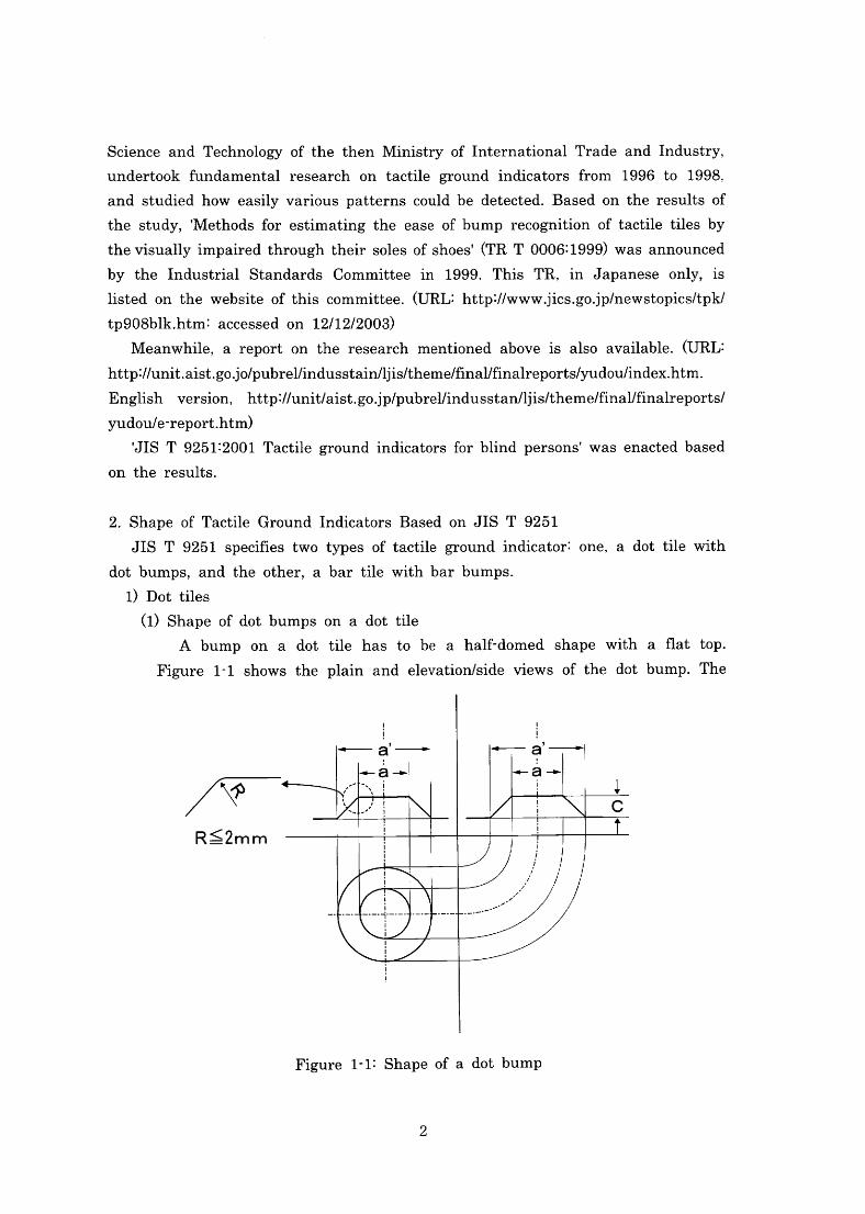
(1)Shape ofdotbumps on a dot tile
A bump on a dot tile has to be a half-domed shape withaflat top・
Figurel-1showsthe plain and elevation/sideviews ofthe dot bump・The
一一丁-a’→1
C
口
///守‾
R≦2mm
Figurel・1:Shapeofa dotbump
2
diameterofthe top ofthe bump(a)is12mm,and that ofthe bottom(a,)=
(a)+10mm,andtheheightofthebump(c)is5mm.Tolerancefor(a)and
(a一)is(+1.5-0)mm each and that of(c)is(+1.0-0)mm.when a product
alterationis made to create roundedges to prevent cornersfromchipplngOr
peoplefrom stumbling,(R)at the corner must beless than2mm.
(2)Size of a Dot Tile
The size of a dot tile shallbe nolessthan300mm square(including
joints)with dots arrangedin parallel.The minimumnumberofdots onone
tileis25(5dotsX5dots).The term‖noless than30mm..refers to the size
Of a standard unitfor a tactile groundindicator,and when a tileislarger
than this,the number of dots shallbeincreased accordingly while
maintainlng the same pattern.
When severaltactile groundindicators arelaid,theintervalbetween two
dot centers oftwo adjoining tiles shallnot exceed theintervalbetween two
dot centers(b)on one tile by morethanlO mm so as to maintain equal
SpaClng between dots across the entire dot tile surface.
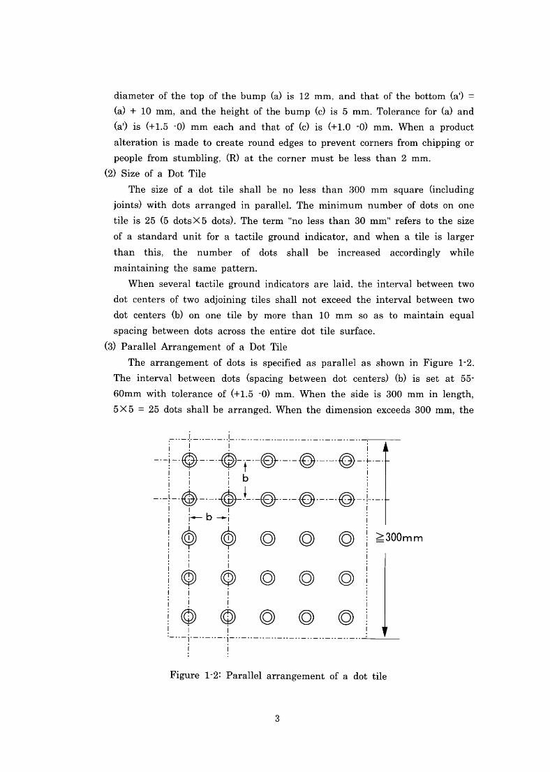
(3)ParallelArrangement ofa DotTile
The arrangement of dotsis specified as parallelas shownin Figurel-2.
Theintervalbetween dots(spacing between dot centers)(b)is set at55-
60mm with tolerance of(+1.5-0)mm.When the sideis300mminlength,
5×5=25dots shallbe arranged.Whenthe dimension exceeds300mm,the
一:一:卜:●
け▲Tb
!⑨・・・
ー◎・-・-◎・-・-・◎-
■l
や・「◎・・・・◎・・・!◎+
◎ ◎ ◎:≧300mm
◎ ◎
◎ ◎
l l
l t
◎ l
‾l-
I l
Figurel-2:Parallelarrangement ofa dot tile
3
number of dots needs to beincreasedin relation to the size ofthe tile.Based
On Calculations,5×5dots glVeS a60mmintervalon a300mm-tile.and
7×7dots glVeS a57.1mmintervalon a400mm-tile,and9×9dots glVeS a
55.6mmintervalon a500mm-tile.Therefbre,theintervalbetween dotsis
denned within a range ofbetween55and60mm.
Furthermore,theintervalrange of55-60mm was determinedin orderto
keep consistent spacing between dots and to establish a standard unitfor
tactile groundindicators.the number of dots、andthelength of(b)when
SeVeraltiles areinstalled side by side.This range enablestheinsta11er to
Choose one oftheintervaloptionswithin this range as a standard distance
when severaltiles arelaid side bv side,butit does not allow theinstaller to -1
vary theintervals(b)within one tile.
2)Bar Tiles
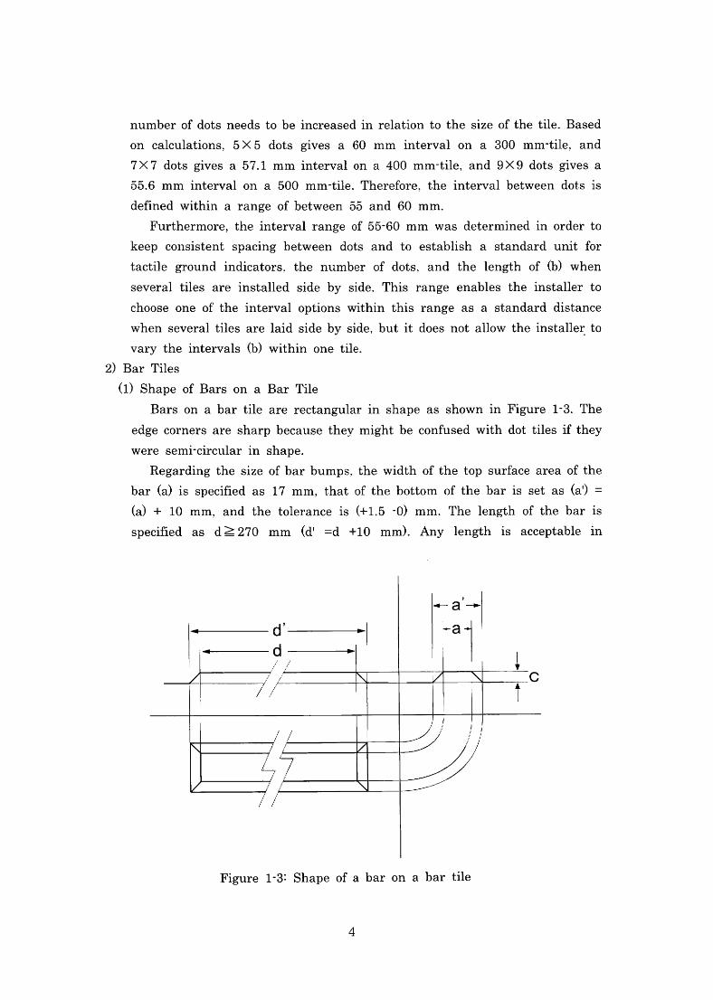
(1)Shape ofBars on a Bar Tile
Bars on a bar tile are rectangularin shape as shownin Figurel-3.The
edge corners are sharp because theymight be confused with dot tilesifthey
Were Semi・Circularin shape.
Regardingthe size ofbarbumps,the width ofthetop surface area ofthe
bar(a)is specified as17mm,thatofthebottom ofthe baris set as(a.)=
(a)+10mm,and the toleranceis(+1.5-0)mm.Thelength of the baris
speci且ed as d≧270 mm(d一 =d +10 mm).Anylengthis acceptablein
ロ
’
↓ ∩
ヨ′ C
/
/「 ∠/ 「
N
Figurel-3:Shape ofa bar on a bar tile
4
PrlnCiple;however,in reality,When theinstallation and the drainage of
rainwater are takeninto account,itis more practicalto dividebartilesinto
an appropriatelength.Based on the standard unit for tactile ground
indicators、the minimumlength ofa bar shallbe270mm.
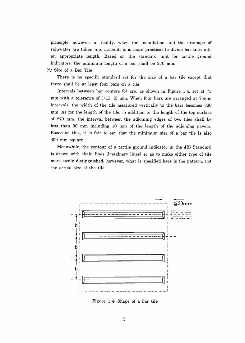
(2)Size of a Bar Tile
There is no specific standard set for the size of a bar tile except that
there shallbe atleast fbur bars on a tile.
Intervals between bar centers(b)are.as shownin Figurel-4,Set at75
mmwithatoleranceof(+15-0)mm.Whenfburbarsarearrangedat75mm
intervals,the width ofthe tile measured vertically tothe bars becomes300
mm.Asforthelengthofthetile,inadditiontothelengthofthetop surface
Of270mm,theintervalbetween the adjoining edges of two tiles shallbe
less than30mmincludinglO mm of thelength ofthe adjoining pavers.
Based on this,itis fair to say that the minimum size of a bar tileis also
300mm square.
Meanwhile,the contour ofa tactile groundindicatorin theJIS Standard
is drawnwithchainlines(imaginarylines)so as to make eithertype oftile
moreeasilydistinguished;however,Whatis speci王iedhereisthepattern,nOt
the actualsize of the tile.
30mm l∠∵=ニ∵=ニ●.丁ニニ●∴
→
」.●:t:-:-」.●:●‥一:■.
L■:-:-:●
■:-
【■:■:
一▲T b l一↑b ll↑b l一
-
一
一
一
-T-:■:- :-.r-
Figurel-4:Shape ofa bar tile
5
(3)Depth ofGrooves and Tolerance
The depth ofa groove onboth dotandbartiles(c)is set as5mm.This
is determined based on experiments to丘nd the appropriate depththatis
detectable but does not at the same time represent an obstacle to
Pedestrians.In addition,in order to secure the minimum depth of5mm,
both tiles have a tolerance ofl’+1mm‖.The width andlength atthe bottom,
(aT)and(d●)、are Calculatedbasedonthe depth of5mm and an angle of45
degrees.
3.Shapes notin Compliance withJIS T9251
Many types oftactile groundindicators are being usedinJapan other than the
OneS StipulatedinJIS T 9251.JIS T 9251was establishedin 2001.and the
Objective was to standardize various patterns that were alreadyin wide use.Itis
not expected that the existingindicators willcomply withJIS requlrementS
immediately,aSthis would be difficult,and therefbre,the co-eXistence ofthosein
COmPliance and notin compliance withJIS requirements wi11continuefor some
ti皿e.
The decision to reject the丘)1lowing types at the time of the establishment of
JIS standard was based on the’一Report of Fundamental Research on Standardization Relating to Tactile Tiles for Guiding the VisuallyImpaired‖
COnducted by Agency ofIndustrialScience and Technology ofthethen Ministry of
InternationalTrade andIndustry from1996to1998.In order to clarifytheintent
Ofthis report,an Outline and the reasonsfor the rejection are provided below.
I 1
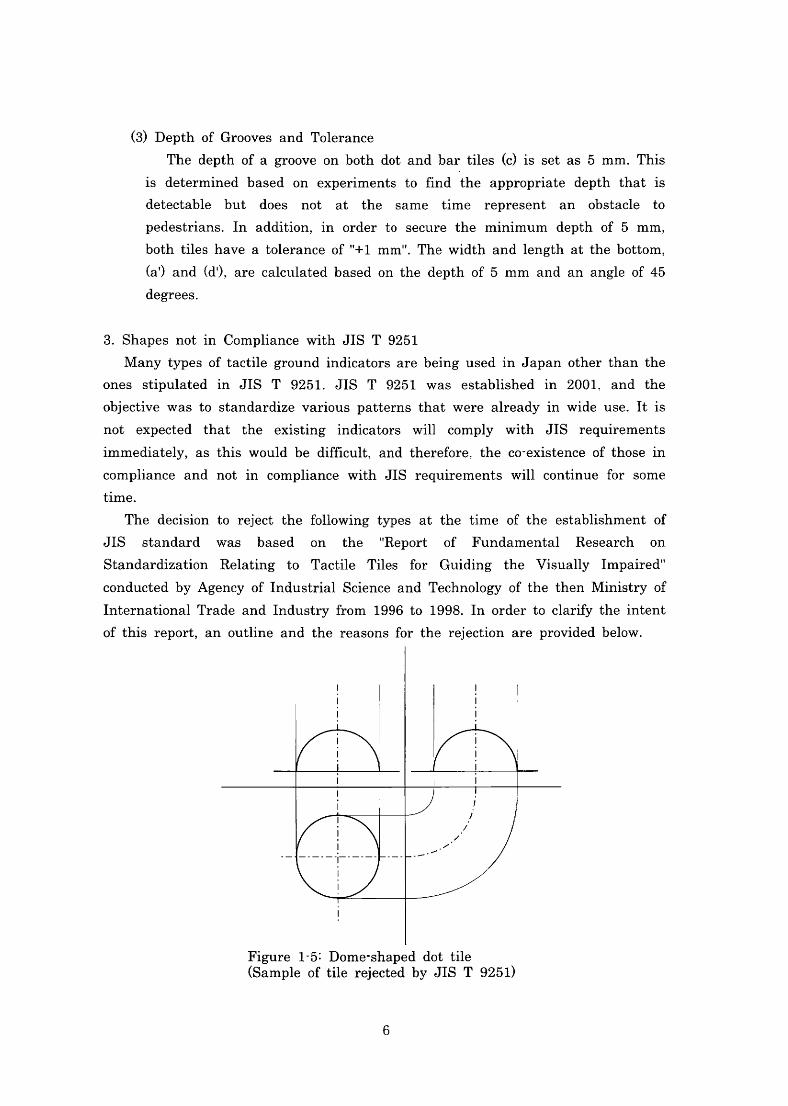
「\、 1
Figurel-5:Dome・Shaped dot tile (Sample oftile r亘ectedbyJIS T9251)
6
1)Dome-ShapedDot Tiles
A dome・Shaped dot tile has dome or cylinder topsinstead offlat tops as
Shownin Figurel-5.Some suggested that domes were slippery,SO this shape
WaS eXCludedfromthe standardization experiments.Itis assumed thatless
dome-Shaped tiles are now used as they glVe a Sharper sensation to soles of
thefeet than semi・dome types.
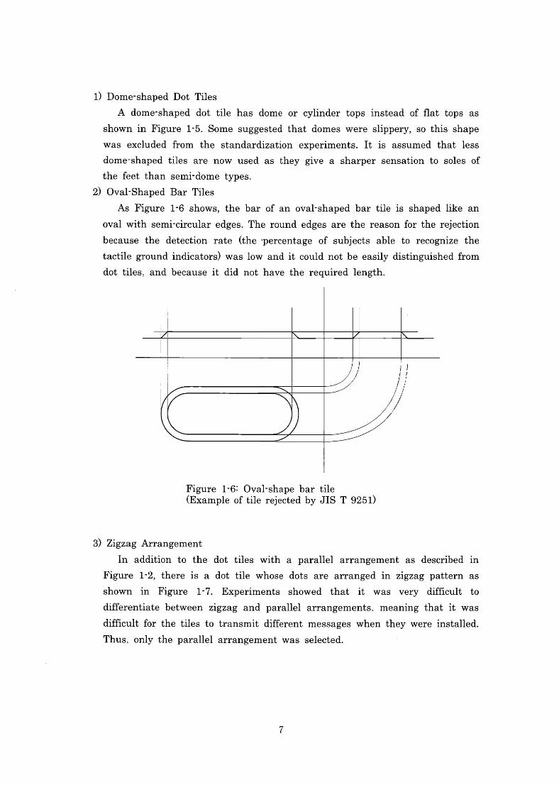
2)Oval-Shaped Bar Tiles
AsFigurel・6shows,the bar ofan oval-Shaped barti1eis shapedlike an
OValwithsemi-Circularedges.Theroundedges arethereasonfbrtherejection
because the detection rate(the・PerCentage Of subjects able to recognize the
tactilegroundindicators)waslowanditcouldnotbeeasilydistinguishedfrom
dot tiles,and becauseit did not have the requiredlength.
Figurel-6:0val-Shape bar tile (ExampleoftilerejectedbyJIST9251)
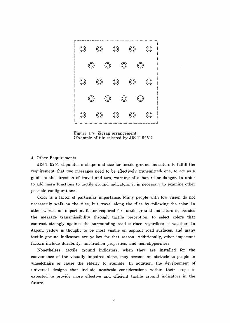
3)ZigzagArrangement
In addition to the dot tiles with a parallel arrangement as described in
Figurelq2,thereis a dot tile whose dots are arrangedin zlgZag Pattern aS
Shownin Figurel・7.Experiments showed thatit was very di瓜cult to
di鮎rentiate between zigzag and parallelarrangements,meanlng thatit was
di疏cult fbr the tiles to transmit diff6rent messages when they wereinstalled.
Thus,Only the parallelarrangement was selected.
7
◎
◎ ◎ ◎ ◎
◎ ◎ ◎ ◎ ◎
◎ ◎ ◎ ◎
◎ ◎ ◎ ◎ ◎
Figurel・7:Zigzag arrangement (ExampleoftilerejectedbyJIST9251)
4.Other RequlrementS
JIST9251stipulates ashape andsizefortactile groundindicatorstofu1fi11the
requlrement that two messages need to be effectively transmitted:one,tO aCt aS a
guide to the direction oftraveland two,Warning ofa hazard or danger.In order
to add morefunctions to tactile groundindicators.itis necessaryto examine other
POSSible configurations.
Coloris a factor of particularimportance.Many peoplewithlowvision do not
necessarily walk on the tiles,but travelalong the tiles by fbllowlngthe color.In
Other words,animportant factor reqtiiredfor tactile groundindicatorsis,besides
the message transmissibility through tactile perception,tO Select colors that
COntraSt StrOngly against the surrounding road surface regardless of weather.In
Japan,ye1lowis thought to be mostvisible on asphalt road surfaces,and many
tactile groundindicators are yellowforthat reason.Additionally,Otherimportant
factorsinclude durability,ant-friction properties,and non・Slipperiness.
Nonetheless,taCtile groundindicators,When they areinsta11ed for the
COnVenience of the visuallylmPaired alone,may become an obstacle to peoplein
Wheelchairs or cause the elderly to stumble.In addition,the development of
universaldesigns thatinclude aesthetic considerations within their scopeis
expected to provide more effbctive and efficient tactile groundindicatorsin the
hture.
8
Chapter2.
Method ofInsta11ation of Tactile GroundIndicators
1.Insta11ation Principles ofTactile GroundIndicators
l)Installation where directionalindicationis necessary
Travelingaloneinopenspaces alwayscauses anxietytopersons withvisual
impalrment Since they are not able to change direction based on vision.They
do not have clues to direct them to their destination,and evenif they did,
they might stillstray丘om a safb path while walking.Bar tiles areinstalled
in order toindicate the direction oftraveland to guidethe user to his or her
destination.
2)Tactile groundindicators shallbeinstalled to alert the user to a possible
danger or toindicate access to the facilities ofthe destination.
There are severalwaysin which visua11yimpaired persons gather
information while walking.Theseinclude tactileinformation or muscle sense
Obtainedvia the soles of thefeet.sensoryinformation conveyed via a white
Cane,and auditoryinfbrmation such as reflected sound,etC.When avisually
impairedpersonwithoutawhitecaneis movingaroundinhazardouslocations,
they can sense obstaclesinfront of them throughreflected sound,but they
CannOt SenSe descending steps orthe depth ofthose steps.Using a white cane
enables them to gather moreinlbrmation:and needless to say,the more
information they have,the more chances there are toincrease safety when
theyencounterpotentialhazards.Therefore,aS aneffbctivesafbtymeasure,dot
tiles sha11beinstalled at potential1y hazardouslocations such as stairs,
railway platforms,Or pedestrian crosslngS.They sha11also beinstalled where
guidanceis necessary and shallbeinstalled atthe end ofbar tiles toindicate
the entrance tobuildings,thelocation ofinformationboards,Orforksinroads.
9
2.Notes onInsta11ation of Tactile GroundIndlCatOrS
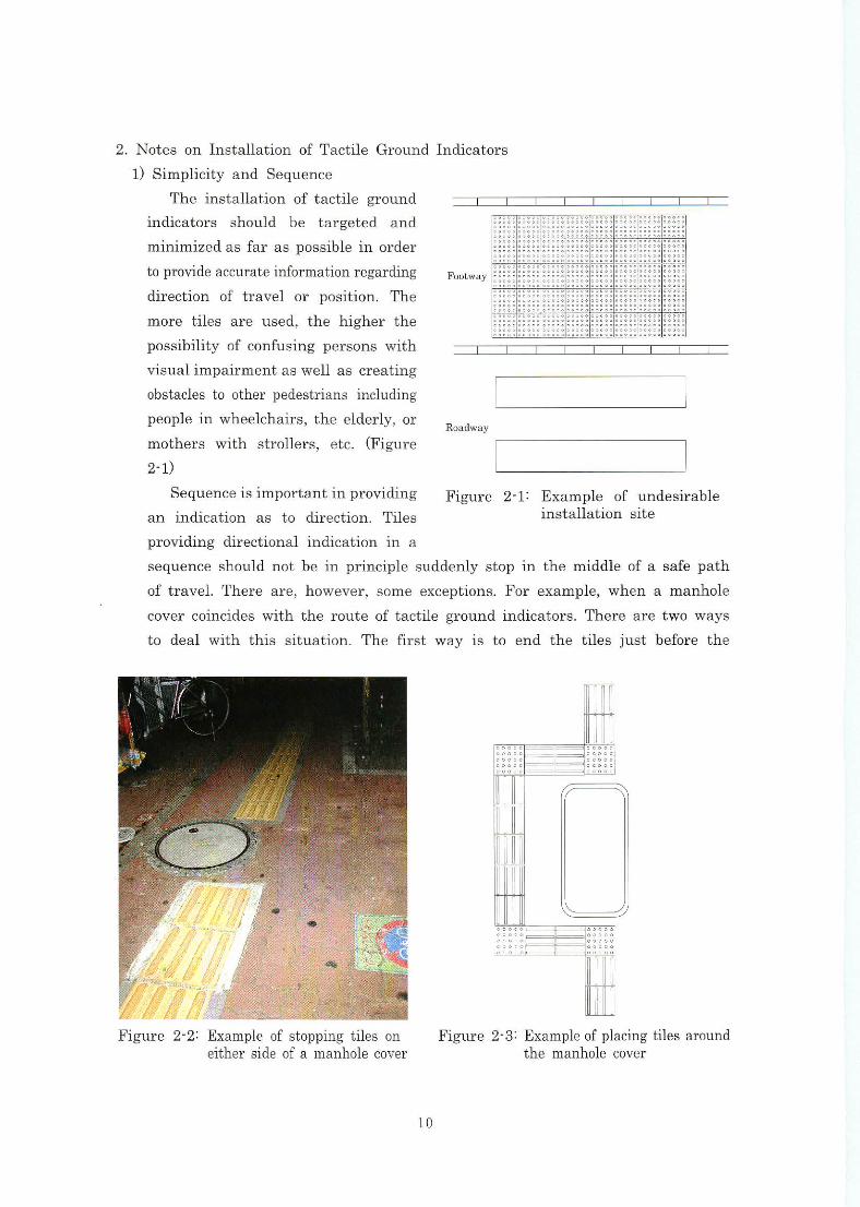
1)Simplicity and Sequence
Theinstal1ation oftactile ground
indicators should be targeted and
minimizedasfara日POSSihleinorder
topiqovideaccurateinformationregarding
direction of travelor position.The
more tiles are used,the higherthe
possibility ofconfusing perβOnSwith
visualimpairmentaswellascreating
obstacles to other pedestrians including
peopleinwheelchairs,theelderly,Or
motherswith strollers,etC.(Figure
2-1)
Sequenceisimportantinproviding
anindication as to direction,Tiles
ぎ00tWay
Road-Ⅳ8y
Figure 2-1:Example of undesirable instal1ation site
PrOviding directionalindicationin a
SequenCe Sho111dnotbeinprinciple suddenlystopinthe middle ofa safe path
Oftravel.There are,however,SOme eXCeptions.For example,When a manhole
covercoincideswiththe route oftactile groundindicators.There are two ways
to dealwiththis situation.The arst wayi邑tO end the tiles just beforethe
Figure2-3:Exampleofplaclngtilesaround the manhole cover
Figure2・2:JJAdmple ofstopplngtiles on either slde of a manhole cover
10
manhole cover and then continuewith themimmediately after.(Figure2-2)
Thesecondwayistoskirtthecoverbyplacingthetilesaroundit.(Figure2-3)
In general,thelatter methodis used.However,When the manhole・COVeris
smal1,thevisua11yimpaired may become dlSOrien七ated becauseofthe鈷・equent
Changesin directionwithin a smallspace.In such a case,theformer method
mayenablethemtomaintainasenseofcontinuitysincetheycan丘ndthetiles
agalnin]uSt tWO Or three8tepS.
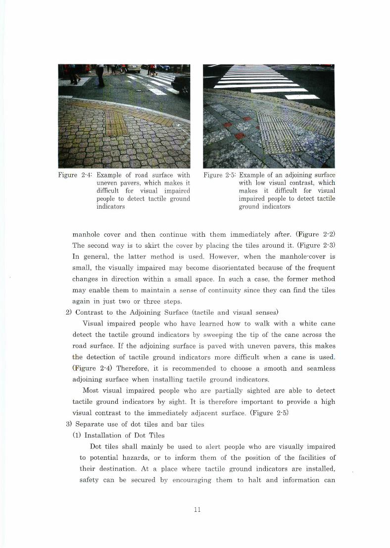
2)Contrast totheAdjoining Surface(tactile andvisualsenses)
Visualimpaired people who havelearned how to walkwith a white cane
detectthe tactile groundindicators by sweeping the tip ofthe cane across the
road surfhce.Ifthe adjoinlngSurfhceis paved withuneVenpaVerS,this makes
the detection of tactile groundindicators more di血cult when a caneis used.
(Figure2-4)Therefore,itis recomlnended to choose a smooth and Beamless
adjoining surface wheninstal1ing tactile groundindicators.
Most visual impaired people who are partially sighted are able to detect
tactile groundindicators by sight.Itis therefbreimportant to provide a high
visualcontrasttotheimmediatelyadjacentsurface.(Figure2-5)
3)Separateuse ofdottiles andbartiles
(1)Instal1ation ofDotTi1es
I)Dt tile8$hallmainly be used to alert people who arevisuallyimpaired
to potentialhazards,Or tOinform them of the position of the facilities of
their destination,At a place where tactile groundindicators areinstalled,
safety can be secured by encouraging them to halt and information can
easily be transmitted.I)ot tiles are generallyinBtal1edin such a waythat
thefront edge of the tileis no closer than30cmfrom the edge ofthe
hazardsuchas stairs,Pedestrian crossings,rOadboundaries,and accessesto
the building8,etCin order to avoid the visionimpaired from stepplnginto
the ha2:ard o工・hazard al・ea.
(2)Installation ofBar Tiles
Bar tiles shal1mainly be used to provide directionalindicationwhere a
personwithvisionimpairmen七wishes to gain access to a facility at the
in七endeddestination.Bar tiles shallbeinstalledin such a waythatbars are
aligned parallelwith andalong the centerline of the reql血ed direetion of
travel.
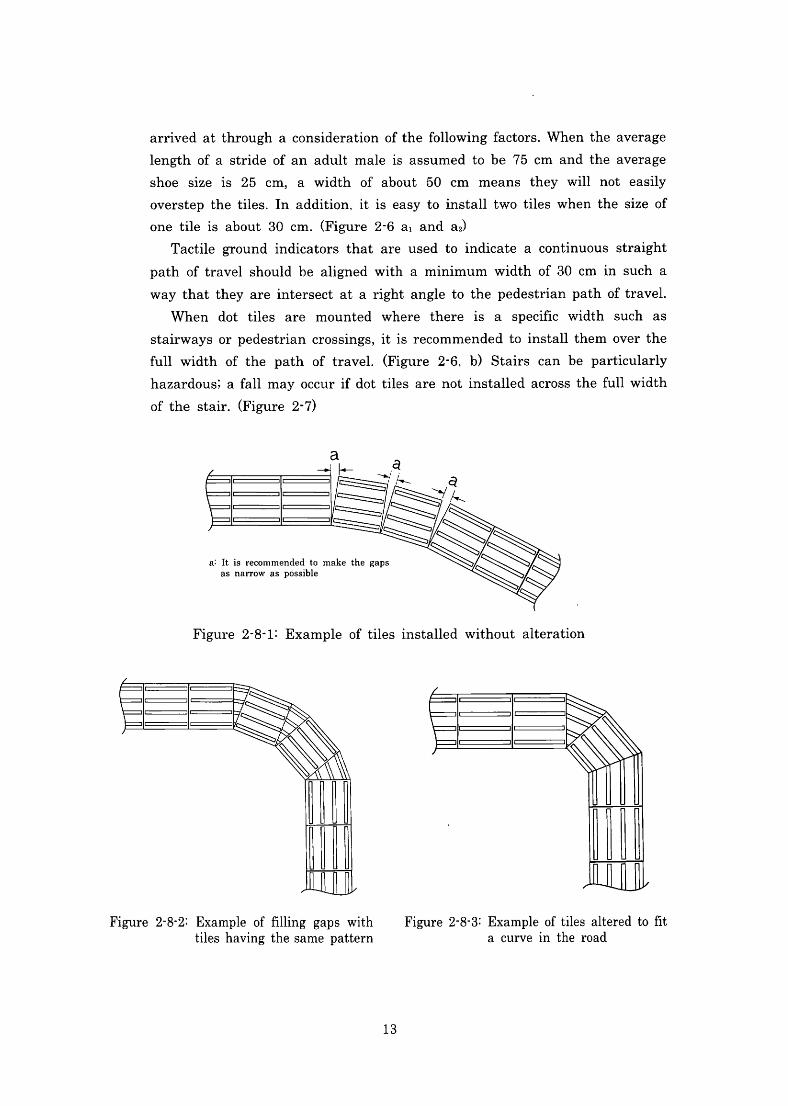
(3)Combined Dot Tiles and王主ar Tiles
When dot tiles arein$talledin con]unCtionwithbar tiles,they shallbe
installed as cloBely as possible to each otller Sincevisuallylmpaired people
wi11feel$Ome anXietyif they were to beinstal1ed apart.If gaps are
unavoidable,at the cornerS for example,itis recommended to丘11the gaps
withthe same patterned tiles.(Figure2-8)
Thereis an exception for white cane users,however,Whenthe dot tiles
areinterruptedby a manhole cover.(Figure2-2)
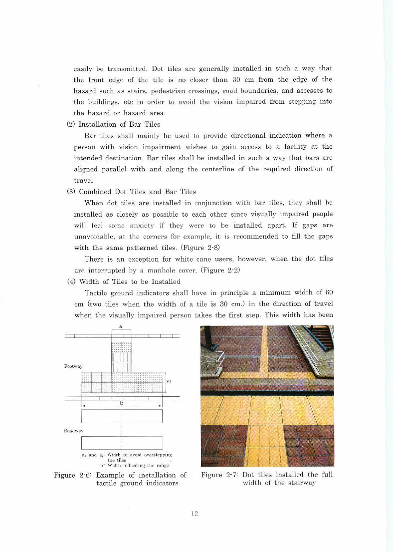
(4)Width ofTi1es to beInstalled
Tactile groundindicators shallhaveinpnnciple aminimum widthof60
cm(two tiles when thewidth of a tileis30cm.)in the direction oftravel
whenthevisuallylmpairedpersontakesthe nrststep.Thiswidthhasbeen
■駅
Footway ] 岨
胴 Ⅶ
誰 ;三:;;;三;… aヱ
aland a空:Width to avoid overskpplng the t止e5
も:Width ul血c且dng ttle ra止ge
Figure2-6:Example ofinstallation of tactile ground indicators
Figure2-7:Dot tileslnStalled thefu11 width ofthe$tairway
12
arrivedatthroughaconsiderationofthefo1lowlngfactors.Whentheaverage
length ofa stride ofan adult maleis assumed to be75cm and the average
shoe sizeis25 cm,a Width of about50cm means they willnot easily
overstep thetiles.Inaddition,itis easytoinstalltwo tileswhen the size of
one tileis about30cm.(Figure2-6aland a2)
Tactile groundindicators that are used toindicate a continuous straight
path oftravelshouldbe aligned with a minimum width of30cmin such a
waythattheyareintersect atarightangletothepedestrianpathoftravel・
When dot tiles are mounted where thereis a speci丘cwidth such as stairways orpedestriancrossings,itisrecommendedtoinstallthemoverthe
fu11width ofthe path of travel.(Figure2-6,b)Stairs can be particularly
hazardous;afallmayoccurifdottiles arenotinstalledacrossthefu11width
ofthe stair.(Figure2-7)
a:Itis recommended to ma上e the gaps as narroff as possible
Figure2-8・1:Example oftilesinstalled without alteration
Figure2-8-2:Example offi11ing gaps with Figure2・8-3:Exampleoftiles alteredtofit tileshavingthesamepattern a CurVeinthe road
13
(5)Installationin the Form ofa Square withoutAlteration
Tactilegroundindicators mayneedtobe alteredto accommodatetheroad
COnditions such as curves or deflections ofguided pathways.When the angle
Ofthe curveis small,itis acceptable tolay squared tiles without alteration.
However,Whenthe gap(a)widens,there aretwowaysto丘11the gap.One:
tonllthegap withtilesofthesamepatterns(Figure2-8-2),andtwo:tofi11
the gap with modified tiles(Figure2-8-3)
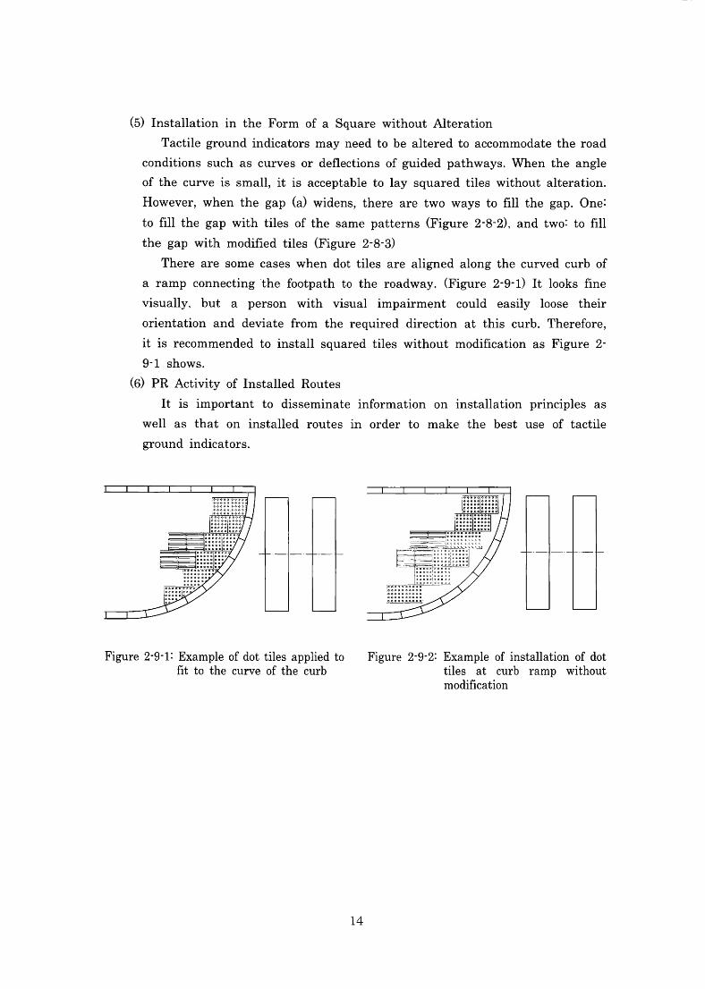
There are some cases when dot tiles are alignedalongthecurvedcurb of
a ramp connectingthefootpath to the roadway.(Figure2-9・1)Itlooks丘ne
visually、but a person with visualimpalrment COuld easilyloose their
Orientation and deviatefrom the required direction atthis curb.Therefbre,
itis recommended toinstallsquared tiles without modi且cation as Figure2-
9-1sbows.
(6)pRActivityofInstalled Routes
Itisimportant to disseminateinfbrmation oninstallation prlnCiples as
we11as that oninstalled routesin order to make the best use of tactile
groundindicators.
Figure2-9-1:Exampleofdottilesappliedto Figure2-9-2:Example ofinstallation ofdot Btto the curve ofthe curb tiles at curb ramp without
modification
14
3.Practicalexamples ofinsta11ation
l)Roads
(1)Footways
Bar tiles shallbe alignedina straightline.Thelocation ofinsta11ationis
preferably 60 cm away from the boundary of private properties. This may
Change depending on the type ofprivate property.
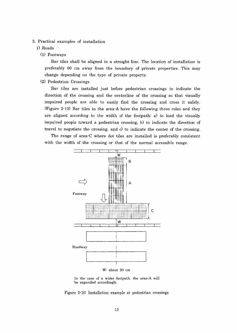
(2)pedestrian Crossings
Bar tiles are installed just before pedestrian crossings to indicate the
direction of the crossing and the centerline of the crossing so that visually
impaired people are able to easily find the crossing and crossit safe1y.
(Figure2-10)Bartilesinthearea-Ahavethefo1lowingthreerolesandthey
are aligned according to thewidth of thefootpath:a)tolead thevisually
impaired people toward a pedestriancrossing,b)toindicate the direction of
traveltonegotiatethecrossing.andc)toindicatethecenterofthecrossing.
The range ofarea-C where dot tiles areinstalledis preferably consistent
With the width ofthe crosslng Or that ofthe normalaccessible range.
W:about 30cm
In the case of a wider footpath. the area-A will be expanded accordingly.
Figure2-10:Installation example at pedestrian crosslngS
15
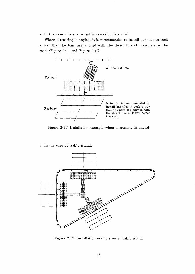
a.In the case where a pedestrian crossinglS angled
WhereacrossinglSangled,itisrecommendedtoinsta11bartilesinsuch
a way that the bars are aligned with the directline oftravelacross the
road.(Figure2・11and Figure2-12)
W:about30cm
Footway
Note:Itis recommended to installbar tilesin such a way that the bars are aligned with the directline of travelacross the road.
Roadway
Figure 2-11: Installation example when a crossing is angled
Figure2-12:Installation example on a trafncisland
16
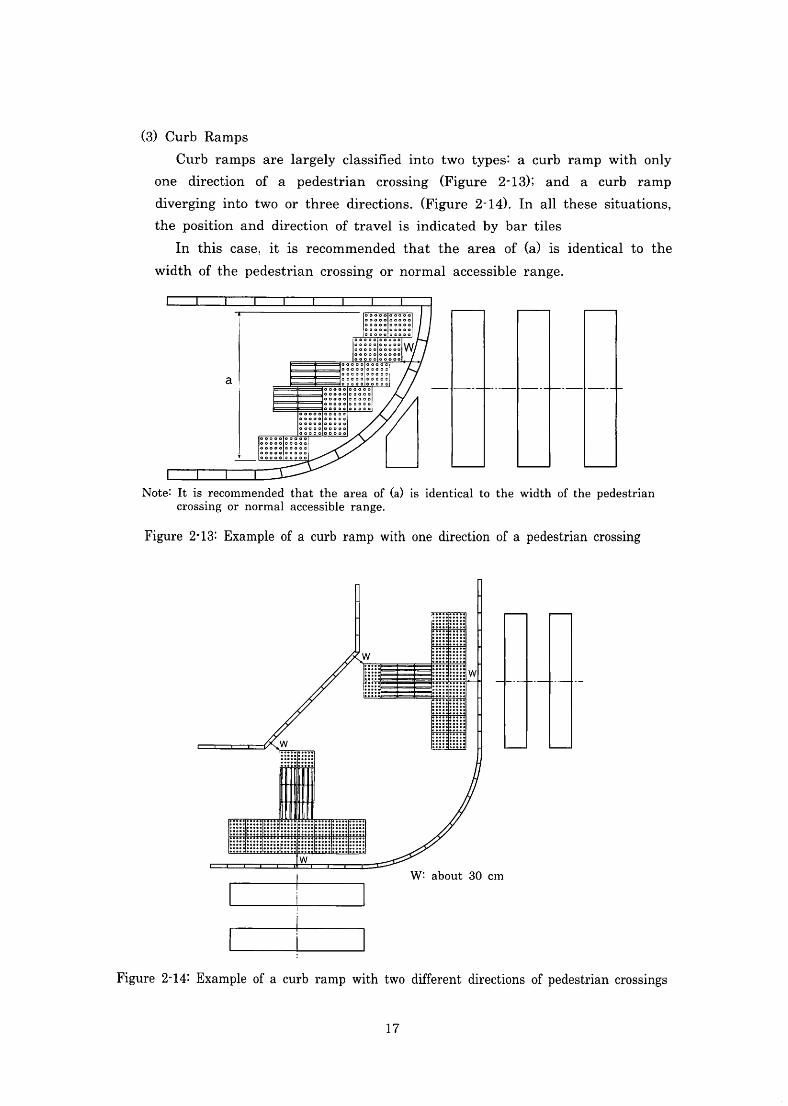
(3)Curb Ramps
Curb ramps arelargely classi且edinto two types:a curb ramp with only
One direction of a pedestrian crossing(Figure 2-13);and a curb ramp
diverginginto two or three directions.(Figure2-14).In allthese situations,
the position and direction oftravelisindicated by bar tiles
In this case,itis recommendedthat the area of(a)isidenticalto the
Width ofthe pedestrian crossing or normalaccessible range.
Note:Itis recommended that the area of(a)isidenticalto thewidth ofthe pedestrian CrOSSlng Or nOrmalaccessible range,
Figure2・13:Exampleofacurbrampwithone directionofapedestriancrossmg
W:about 30cm
L [1二]
Figure2-14:ExampleofacurbrampwithtwodiffbrentdirectionsofpedestriancrosslngS
17
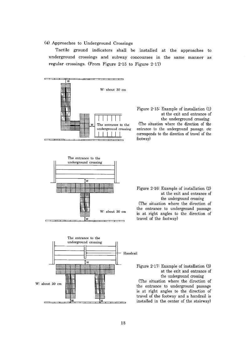
(4)Approachesto Underground Crossings
Tactile ground indicators shall be installed at the approaches to
underground crossings and subway concoursesin the same manner aS
regularcrossings.(From Figure2・15to Figure2-17)
Figure2-15:Exampleofinstallation(1)
atthe exit and entrance of the underground crossing
(The situation wherethe direction ofthe entrance to the underground passage.etc
COrreSPOndstothedirectionoftravelofthe 払otway)
Figure2・16:Exampleofinstallation(2) at the exit and entrance of theundergroundcrosslng
(The situation where the direction of the entrance to underground passage is at right angles to the direction of travelofthefootway)
The entrance to the
undergro11nd crosslng
Handrail
Figure2-17:Exampleofinstallation(3) at the exit and entrance of theundergroundcrosslng
(The situation where the direction of the entrance to underground passage is at right angles to the direction of
travelofthefootwayandahandrailis installedinthecenterofthe stairway)
W:about30cm
18
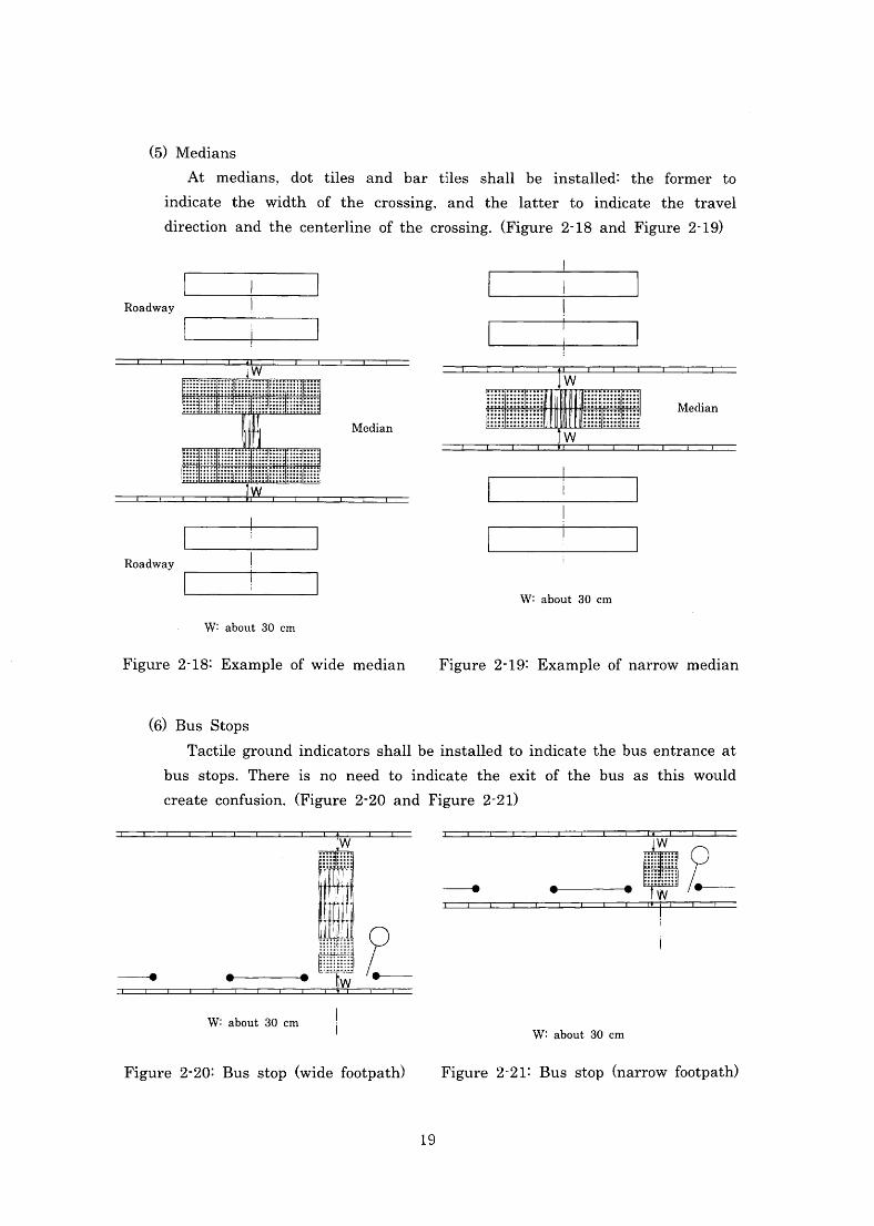
(5)Medians
At medians,dot tiles and bar tiles shallbeinstalled:the fbrmer to
indicate the width of the crossing,and thelatter toindicate the travel
direction andthe centerline ofthe crossing.(Figure2-18and Figure2-19)
.l
Roadway
「 ト讐
Roadway
W:about30cm
W:about30cm
Figure2-18:Example ofwide median Figure2-19:Example ofnarrow median
(6)Bus Stops
Tactile groundindicators shallbeinstalledtoindicate thebus entrance at
bus stops.Thereis no need toindicate the exit of the bus as this would
create confusion.(Figure2-20and Figure2-21)
幸 手 壬
W:about30cnl W:about 30cm
Figure2・20:Bus stop(widefbotpath) Figure2-21:Bus stop(narrowfbotpath)
19
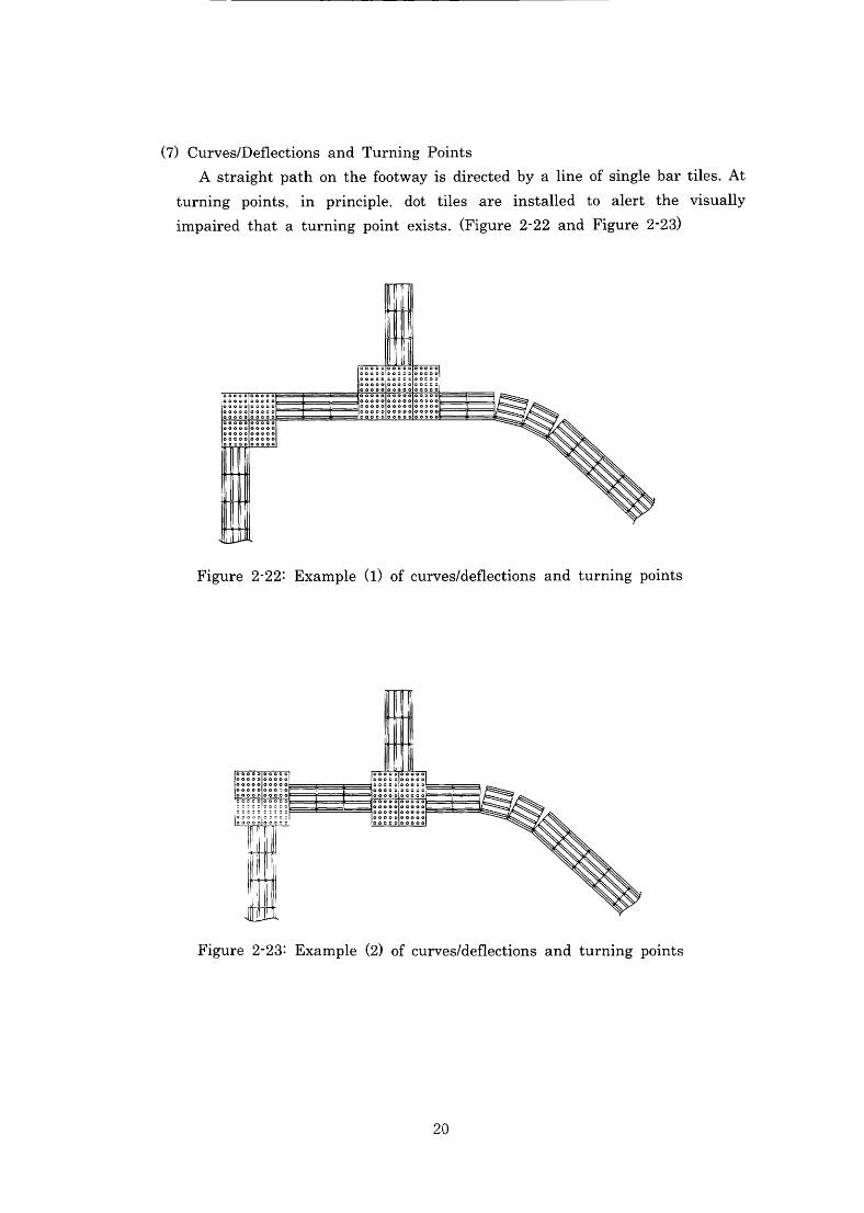
(7)Curves/Deflections and Turning Points
Astraight pathonthefootwayisdirectedbyalineofsinglebartiles・At
turning points,in prlnCiple.dot tiles areinstalled to alert the visually
impairedthataturningpoint exists.(Figure2-22and Figure2・23)
Figure2-22:Example(1)ofcurveS/deflections and turning points
Figure2-23:Example(2)ofcurveS/deflections and turning points
20
2)mblic Transport
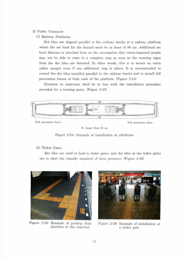
(1)Railway Platforms
Dot tiles are aligned parallel to the railway tracks at a railway platform
where the set backfor the hazard must be atleast of80cm.Additionalset
backdistanceisprovidedhereonthe assumptionthatvision-impairedpeople
may not be able to come to a complete stop as soon as the warning signs
from the dot tiles are detected.In other words,thisis to secure an extra
Safety皿argin evenif one additlOnal日tepi8taken.Itis recommended to
extendthe dottilesinstalledparalleltotherai1waytracks andtoinstal1fall
preventionfencesatbothendsoftheplatfbrm.(Figure2-24)
Direction to stairways shal1beinlinewiththeinstallation prmciples
providedfor a tumingpoint.(Figure2・25)
Fall prevention fence Fan pl・eVention fen(:e
W:longertban80cm
Figure2-24:Example ofinstallation at platforms
(2)Ticket Gates
Barti1es are usedtoleadtoticket gates,and dottiles attheticketgates
aretoalertthevisual1yimpairedoftheir presence.(Figure2-26)
」■L Figure2-25:Examplヒuiguidingfrom
platformtothe stairway Figure2-26:Exampleofinstallation at
a ticket gate
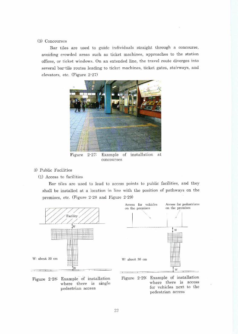
(3)concourses
Bar tiles are used to guideindlviduals straightthrough a concourse,
avoiding crowded areas such as ticket machines,aPPrOaChes tothe station
Ofnces,Orticketwindows・Onanextendedline,thetraveirotltedivergesinto
SeVeralbar-tileroutesleadingtoticketmachines,ticketgates,Stairways,and
eユevators,et℃.伊igure2-27)
COnCOurSPS
3)Public Facnities
(1)Access to facilities
Bar tiles are used tolead to access points to puhlic faeilities,and they
Shallbeinstalledatalocationinlinewiththepositionofpathwaysonthe
pre皿壷es,etC.(F卸汀e2-28andFigwe2-29)
Acce色白 fDr Vellicle8 Access払r pedestrians Onthepre叩i自es ontもe premises
Figure 2-29:Example ofinstal1ation where there i8 aCCeS$ 血r velユicles next to the pedestrian aceess
馴鹿皿e 2-28:Example ofinstallation where thereis single pedestlユan aCCeSS
22
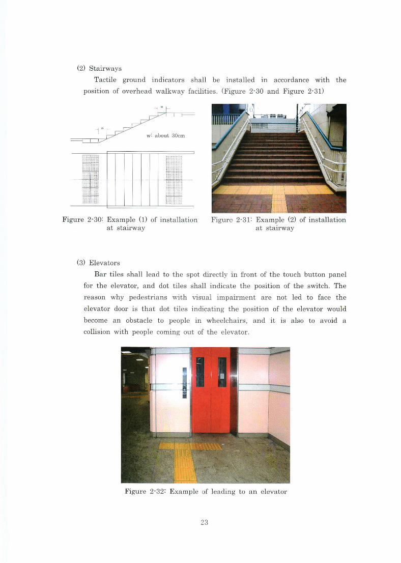
(2)Sta元ways
Tactile ground indicators shall be installed io accordance with the
position ofoverhead walkwayfacilities.(Figure2-30and Figure2-31)
l
Figure2-30:Example(1)ofinstallation at stairway at sta止way
(3)Elevators
Bartiles shallleadtothe spotdlreCtlyinfront ofthetouchbuttonpanel
fbr the elevator,and dot tileB Shal1indicatethe position ofthe switch.The
reason why pedestrianS with visualimpaument are nOtled to facethe
elevator dooris that dot tilesindlCatingthe position ofthe elevator would
become an obstacle to peoplein wheelchairs,anditis also to avoid a
COnisionwith people coming out ofthe elevator.
Figure2-32:Example ofleading to an elevator
23
Chapter3.
MobilitywithTactile Ground SurfaceIndicators
l.Basic TravelSkills fbr Persons with VisualImpalrment
l)Protection and Trailing
(1)Protection
一.Protection”is the ability to move aboutindependentlyindoors with
maximum safbty.It can befurther dividedinto upper body protection and
lower body protection.
Whilein the protection position,maintain an upright posture without
swinglngthe arms andplacetheupper arm so thatitis at an angletothe
targetobject.Inotherwords,Whilepassingalongcorridors orthroughdoors,
the upper armis extended out to the side horizontally to allow easy
detection of vertically placed objects.When passing by objects on the noor
such as desks or handrails,the upper armis held downwards・
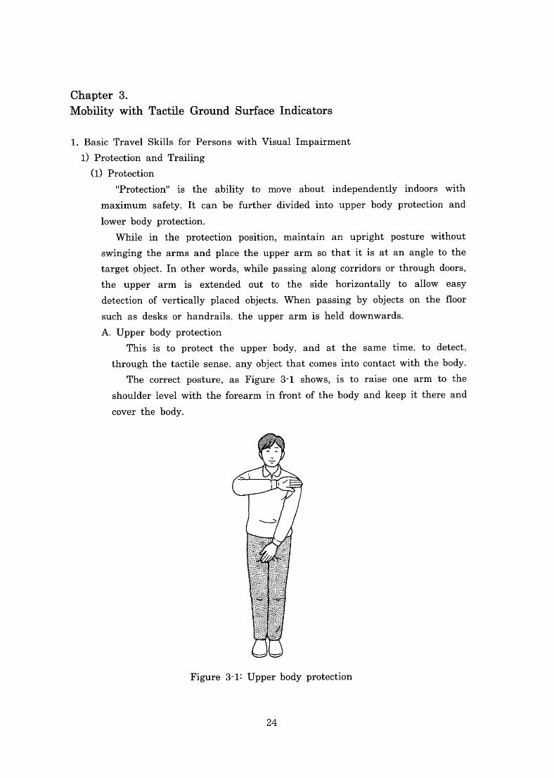
A.Upper body protection
Thisis to protect the upper body,and at the same time・tO detect,
throughthetactilesense,anyObjectthatcomesintocontactwiththebody・
The correct posture,aS Figure3-1shows,is to raise one arm to the
shoulderlevelwith theforearminfrontofthebody andkeepitthere and
COVer the body.
華芋こご+二
Figure3-1:Upperbody protection
24
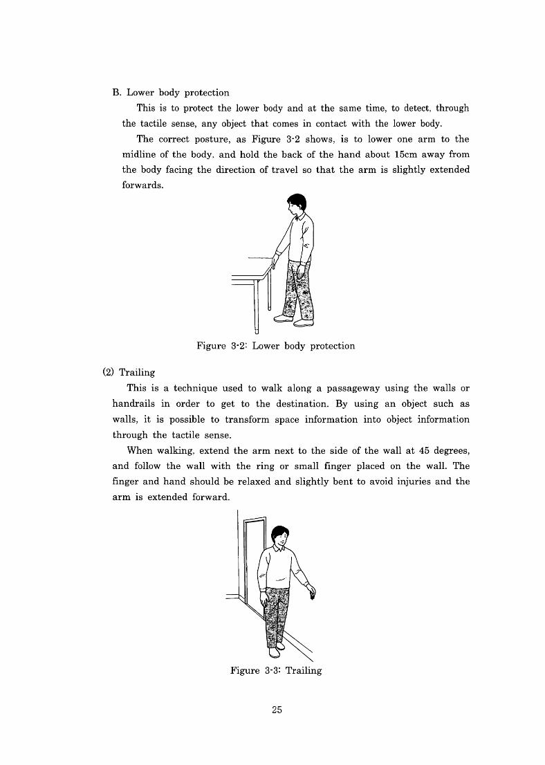
B.Lower body protection
Thisis to protect thelower body and at the same time,tO detect,through
the tactile sense,any Object thatcomesin contactwiththelowerbody.
The correct posture,aS Figure3-2shows,is tolower one arm to the
midline ofthe body,and hold the back ofthe hand about15cm awayfrom
the bodyfacingthe directionoftravelsothat the armis slightly extended
hrwards.
Figure3-2:Lower body protection
(2)Trailing
This is a technique used to wallr along a passageway using the walls or
handrailsin order to get to the destination.By uslng an Object such as
Walls,itis possible to transfbrm spaceinformationinto objectinformation
throughthe tactile sense.
When walking,eXtendthe armnexttothe side ofthe wallat45degrees,
andfo1low the wallwiththe rlng Or Smallfinger placed on the wall.The
負ngerandhandshouldberelaxedandslightlybentto avoidin]uries andthe
armis extended fbrward.
Figure3・3:Trailing
25
2)Basic Cane Techniques
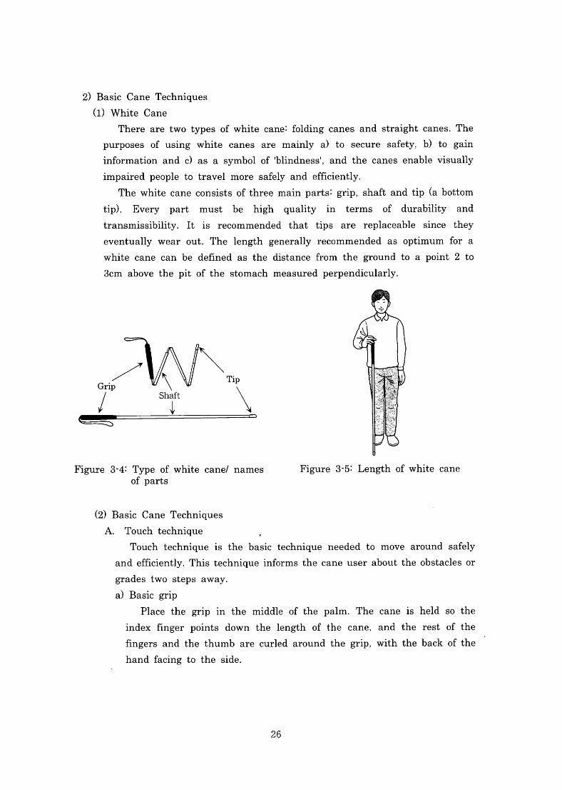
(1)White Cane
There are two types ofwhite cane:fo1dingcanes and straight canes・The
purposes of using white canes are mainly a)to secure safety.b)to gain
information and c)as a symbolof-blindnessl,and the canes enable visually
impaired people to travelmore safely and efficiently.
Thewhitecaneconsistsofthreemainparts:grip,Shaftandtip(abottom
tip).Every part must be high qualityin terms of durability and
transmissibility.Itis recommended that tips are replaceable since they
eventually wear out.Thelengthgenerally recommended as optimumfor a
white cane can be de負ned as the distancefrom the ground to a point2to
3cm above the plt Ofthe stomach measured perpendicularly.
月\Tiて Gri 1y st
\
Figure3-5:Length ofwhite cane Figure3-4:Type ofwhite cane/names Ofparts
(2)Basic Cane Techniques
A.Touch technique ,
Touch techniqueis the basic technique needed to move around saf61y
andefficiently.Thistechniqueinformsthecaneuserabouttheobstaclesor
grades tWO StePS aWay.
a)Basic grip
Place the gripin the middle of the palm.The caneis held so the
index finger points down thelengthof the cane.and the rest of the
fingers andthe thumb are curled around the grlP.Withthe back ofthe
hand facing to the side.
26
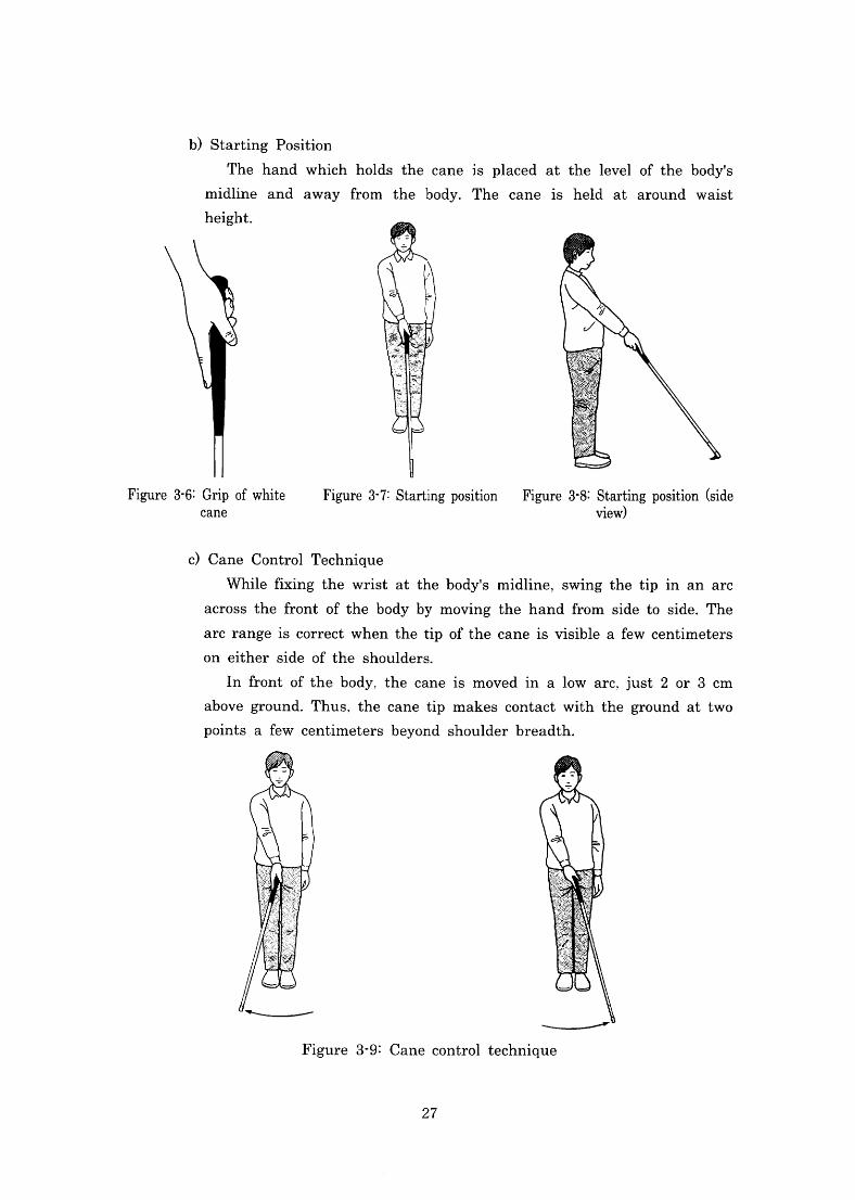
b)StartingPosition
The hand which holds the caneis placed at thelevelofthe body-s
midline and awayfrom the body.The caneis held at around waist
height.
Figure3-7:Startingposition Figure3・8:Startingposition(side view)
Figure3・6:Grip ofwhite
Cane
c)Cane ControITechnique
While丘Ⅹing the wrist at the body-s midline,SWlng the tipin an arc
across thefront ofthe bodyby movlng the hand丘om side to side.The
arcrangeiscorrect whenthetlp Oft・hecaneisvisibleafewcentimeters
on either side of the shoulders.
Infront ofthe body.the caneis movedin alow arc.just20r3cm
above ground.Thus.the cane tip makes contact withthe ground at two
POints a few centimeters beyond shoulder breadth.
27
Next,the rhythm of the cane swing and the correct timing for
Walking are explained.Asthe right fbot moves fbrward,the tip of the
cane checks the ground in front and a little bit. to the side of the
OPPOSite fbot.As theleftfoot moves払rward,the tip ofthe cane checks
the groundin丘ont and alittlebit to the side ofthe opposite fbot.The
foot should touch the ground at the same time the cane comesinto
COntaCt With the ground.
B.Constant Contact
The const-ant COntaCt teChnique means keeplng the cane tip constantlv -1
in contact with the groundinstead ofliftingit off.By sliding the tip
Sideways alongthefl00r Surface,mOreinformation about the travelsurface
is obtained to allow safer movement.This techniqueis particularly usefu1
When movlngaCrOSS a SmOOth surface orapossiblyhazardousareasuchas
railway platforms.
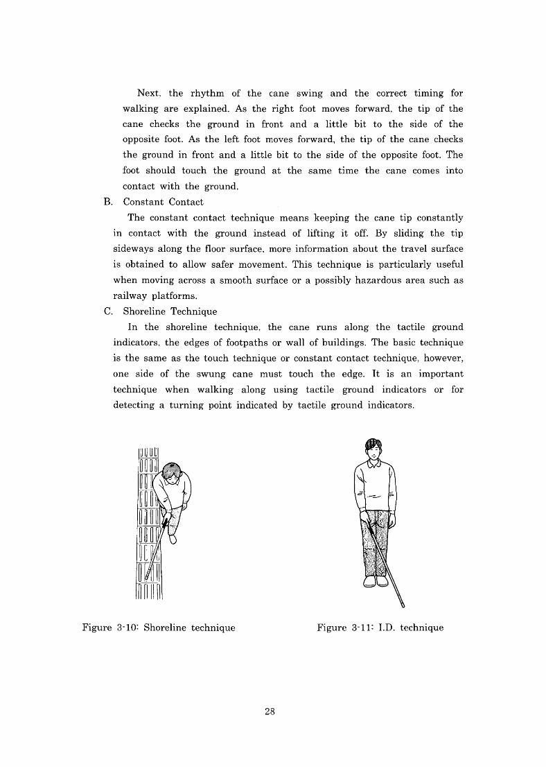
C.Shoreline Technique
In the shoreline technique,the cane runs along the tactile ground
indicators、the edges offootpaths or wa1lofbuildings.The basic technique
is the same as the touchtechnique orconstantcontacttechnique,however,
One Side of the swung cane must touch the edg・e.Itis animportant
technique when walking along using t.actile ground indicators or for
detecting a turning pointindicated by tactile groundindicators.
Figure3-10:Shoreline technique Figure3-11:Ⅰ.D.technique
28
D.Ⅰ.D.Technique
Thisteclmiqueis generallyusedbypeople withlowvisionwho are able
to navigate using their residualvision.The grlpis heldinthe same way
as the touch technique and the wristis twistedinward.Inthis case,itis
allright to curve theindex丘nger around the grlPwith the thumb held
Straightagainstthecane grlp.The caneishelddiagonalagalnStthebody’s
midline,holding the grlp at thewaistlevel,bringlngthe tip ofthe cane a
little bit to the side ofthe opposite fbot.
The caneis held steadily and slightly offthe ground.
3)MovingAroundwithResidualVision
Persons with vision impairment often use their residual vision as a way of
COllectlnginLbrmation on the surrounding environment.Most of the tactile
groundindicators are colored ye1low:their clarity/1uminance create a clear
COntraSt Withthe adjoiningpavement.Itis therefore easyto see theindicators
On the road surface、enabling visualimpaired people move around using their
residualvision.However,SOmeOne With particularly poor residualvision may
not・always be able toidentify an Object correctly:therefore,thereis a
possibilitythatanobject detectedbyresidualvision maybe misidenti且ed,thus
increasing the risk of travel.Itis recommended,therefbre、tO discuss with
trainees whether they should use their residual vision or rely more heavily on
the other senses to ensure safb movement.
An orientation and mobility specialist shall instruct trainees so that the
utilization of residualvision and the white cane techniques complement one
another.The combined use of the visualinformation and white cane means
that the various senses canbe appropriatelyutilized,dependingonthe nature
Of a glVen Situation.It must bealso noted that excessive reliance on vision
COuld actually reduce the safety ofthevisuallyimpaired.Moving around with
residualvision also requlreS basic techniques such as fbrmulation of a mental
map and knowing how to remain orientated while walking.However,SuCh
techniques are often neglected when t・hevisionimpaired rely too much on
residualvision.Itis necessary to understand the slgnilicance of the visual
informationreceivedandtoexercisejudgmentselectivelywhenhelpingtrainees
recogruzelandmarksfrom among the availablevisualinformation.
29
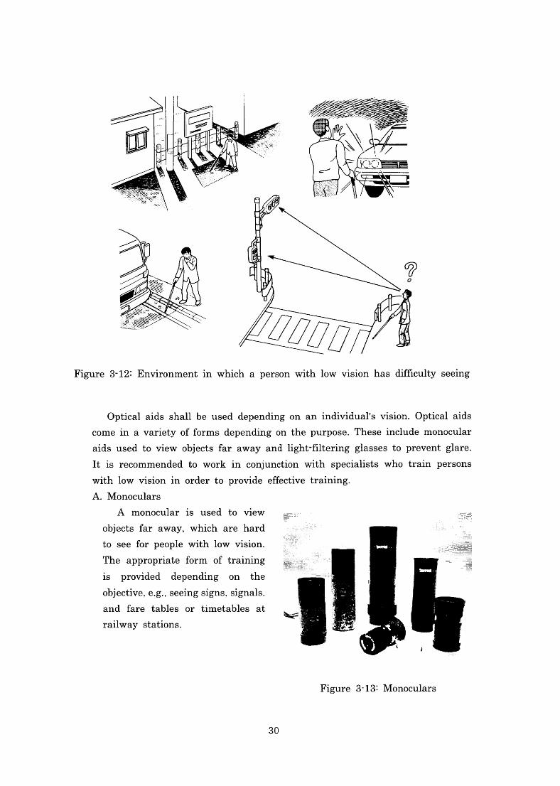
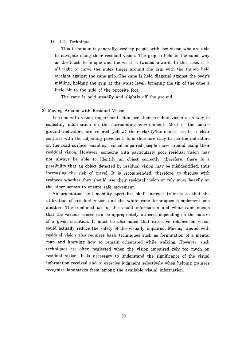
Figure3・12:Environmentin which a personwithlow vision has dimculty seelng
Opticalaids sha11be used depending on anindividual-s vision.Opticalaids
comein avarietyoffbrms dependingonthe purpose.Theseinclude monocular
aids used to view objects far away andlight-mtering glasses to preventglare.
Itis recommended to workin con]unCtionwith specialists who train persons
Withlowvisionin order to provide e鮎ctive training・
A.Monoculars
A monocular is used to view
Objects far away,Which are hard
to seefor peoplewithlowvision.
The appropriate fbrm of training
is provided depending on the
Objective,e.g.,SeeingslgnS,Slgnals.
and fare tables or timetables at
railway stations.
Figure3-13:Monoculars
30
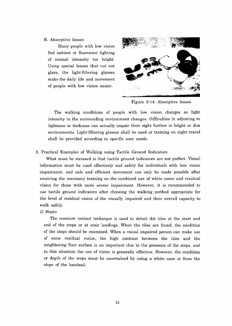
B.Absorptivelenses
Many people with low vision
find ambient or fluorescent lighting
Of normalintensity too bright.
Using speciallenses that cut out
glare,thelight-filtering glasses
makethedailylifeand movement
Ofpeople withlow vision easier.
■■-r一一一t▲一一一三蔓テi亡†山⊥よ三■ン・▲一--・f一一・-」一-‾‾‾‾
Figure3・14:Absorptivelenses
The walking conditions of people withlow vision changes aslight
intensityinthe surroundingenvironmentchanges.Difficultiesinadjustingto
lightnessordarknesscanactuallyimpairtheirsightfurtherinbrightor dim
environments.Light一別teringglasses shallbeusedortrainingonnighttravel
Shallbe provided according to specific user needs.
2.PracticalExamples ofWalking usingTactile GroundIndicators
Whatmustbe stressedisthattactilegroundindicators arenotperfbct.Visual
infbrmation must be used effbctively and safbly fbrindividuals withless vision
impairment.and safeand efncient movement can only be made possible after
receivingthenecessarytrainingonthecombineduseofwhitecanes andresidual
vision fbr thosewith more severeimpalrment.However,itis recommended to
use tactile ground indicators after choosing the walking method appropriate for
thelevelofresidualvision ofthevisuallyimpaired and their overallcapacity to
Walk safe1y.
1)Stairs
The constant contact techniqueis used to detect dot tiles at the start and
end ofthe steps or at stairlandings.When the tiles arefound,the condition
Ofthestepsshouldbeexamined・Whenavisualimpairedpersoncanmakeuse Of some residualvision,the high contrast between the tiles and the
neighboringfl00rSurfaceisanimportantcluetothepresenceofthesteps.and
inthis situationtheuseofvisionisgenerallye鮎ctive.However,thecondition
Or depth ofthe steps must be ascertained by uslng a White cane or ffom the
Slope ofthe handrail.
31
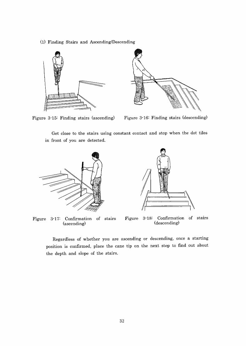
(1)Finding Stairs andAscending/Descending
Figure3-15:Findingstairs(ascending) Figure3-16:Findingstairs(descending)
Getclose tothe stairs usingconstantcontact and stop whenthe dot tiles
in front ofyou are detected.
Figure 3-18:Connrmation of stairs (descending)
Figure 3-17:Confirmation of stairs (ascending)
Regardlessofwhetheryou are ascendingor descending,OnCea Starting
positionisconnrmed,Placethecanetiponthenextsteptonndoutabout・
the depth and slope ofthe stairs・
32
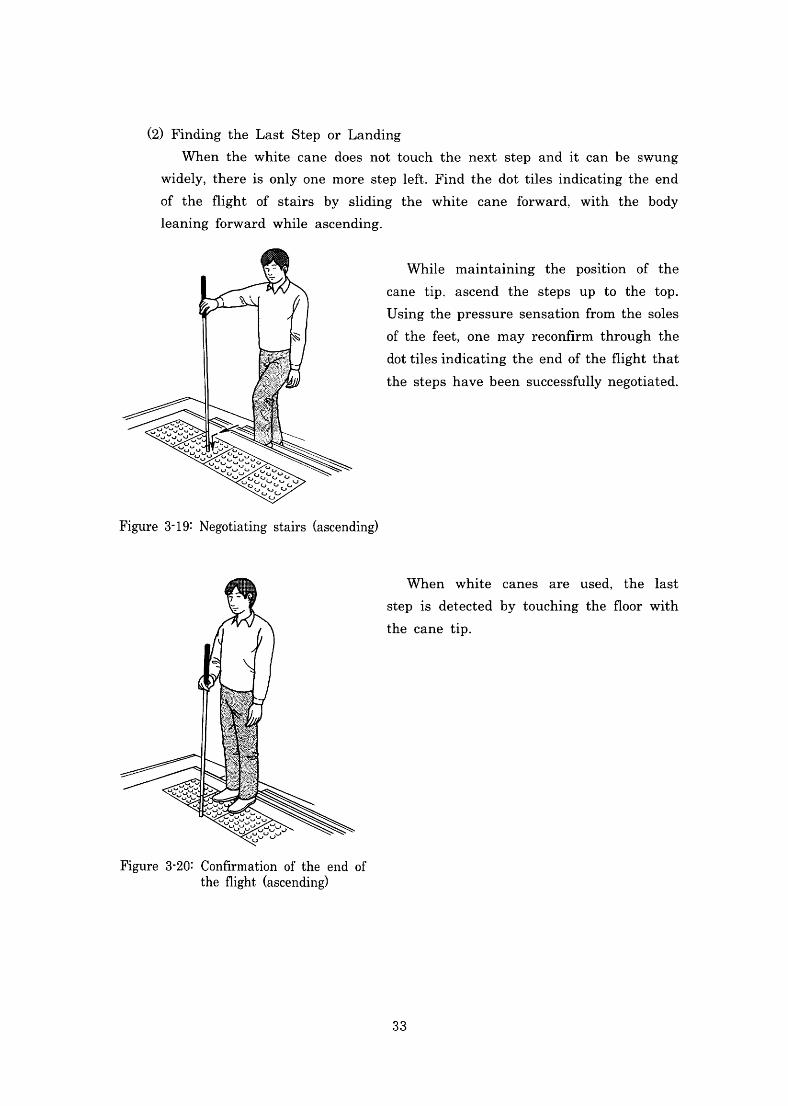
(2)Findingthe Last Step or Landing
When the white cane does not touch the next step andit can be swung
widely,thereisonlyonemorestepleft・Findthedottilesindicatingtheend
of theflight of stairs by sliding the white caneforward,With the body
leaningforward while ascending.
While maintaining the position of the
cane tip.ascend the steps up to the top・
Usingthepressuresensationfromthesoles
ofthe fbet,One may reCOnLirmthroughthe
dottilesindicatingthe endoftheflightthat
the stepshavebeensuccessfu11ynegotiated・
Figure3-19:Negotiatingstairs(ascending)
When white canes are used,thelast
stepis detected by touching the noorwith
the cane tip.
Figure3-20:Confirmation ofthe end of theflight(ascending)
33
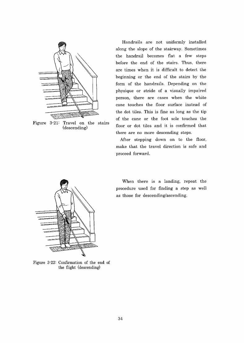
Handrails are not uniformly installed
along the slope ofthe stairway.Sometimes
the handrail becomes flat a few steps
before the end ofthe stairs.Thus,there
are times whenitis difncult to detect the
beginning or the end of the stairs by the
form of the handrails・Depending on the
physique or stride of a visually impaired
person,there are cases when the white
cane touches the floor surface instead of
thedottiles.Thisis且neaslongas thetip
Of the cane or the foot sole touches the
fl00r Or dot tiles anditis confirmed that
there are no more descending steps.
After stepplng down on to the fl00r,
make that the traveldirectionis safeand
PrOCeed fbrward.
Figure 3-21:Travelon the stairs (descending)
When thereis alanding,rePeat the
PrOCedure used for丘nding a step as well
as thosefor descending/ascending.
Figure3-22:Confirmation ofthe end of theflight(descending)
34
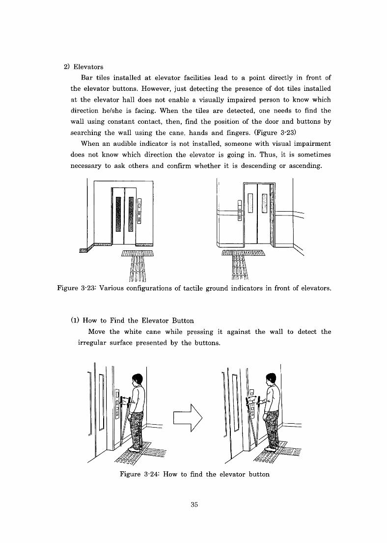
2)Elevator
Bar tilesinstalled at elevator facilitieslead to a point directlyinfront of
theelevatorbuttons.However,justdetectingthepresenceofdottilesinstalled
atthe elevatorha11does notenable avisuallyimpairedpersontoknowwhich
direction he/sheis facing.When the tiles are detected,One needs to且ndthe
walluslngCOnStantCOntaCt,then,丘ndthepositionofthedoorandbuttonsby
searchingthewa11usingthecane,handsandfingers.(Figure3-23)
Whenan audibleindicatorisnotinstalled,SOmeOne Withvisualimpalrment
does notknow which directionthe elevatoris golngln・Thus,itis sometimes
necessarytoaskothersandconnrmwhetheritis descendingorascending・
Figure3-23:Variousconngurationsoftactilegroundindicatorsinfrontofelevators・
(1)How to Findthe Elevator Button
Move the white cane while pressingit agalnSt the wallto detect the
irregular surface presented by the buttons.
Figure3-24:How to丘nd the elevator button
35
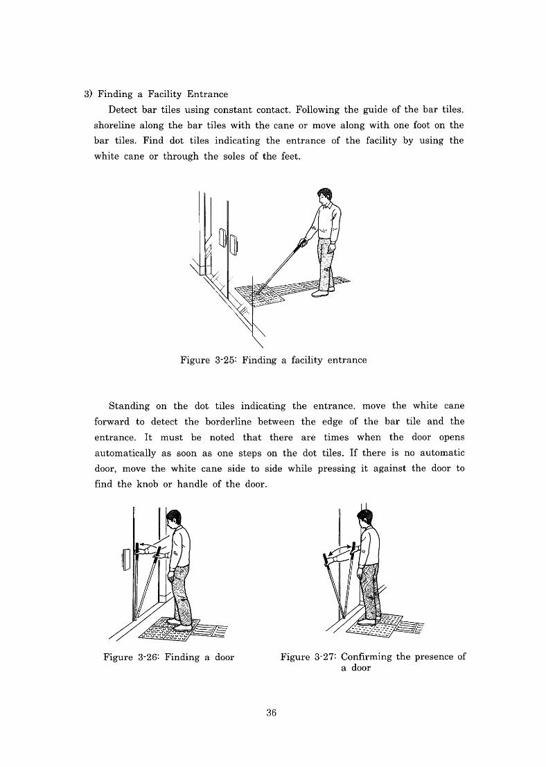
3)Finding a Facility Entrance
Detectbartiles usingconstantcontact.Followingthe guide ofthe bar tiles,
Shoreline along the bar tiles with the cane or move along with one fbot on the
bar tile$.Find dot tilesindicating the ent・ranCe Of the facility by using the
White cane or throughthe soles ofthefeet.
Figure3・25:Finding a facility entrance
Standing on the dot tilesindicating the entrance,mOVe the white cane
forward to detect the borderline between the edge of the bar tile and the
entrance.It must be noted that there are times when the door opens
automatically as soon as one steps on the dot tiles.If thereis no automatic
door,mOVe the white cane side to side while pressingit against the door to
丘nd the knob or handle of the door.
Figure3-27:Confirmingthe presence of a door
Figure3・26:Finding a door
36
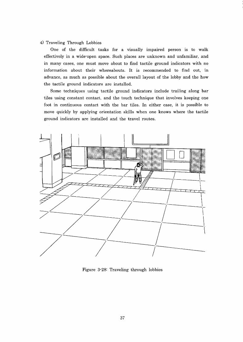
4)TravelingThroughLobbies
One of the difncult tasks for a visuallyimpaired personis to walk
efftctivelyin a wide-OPen SpaCe.Such places are unknown and unfamiliar,and
in many cases,One muSt mOVe about to丘nd tactile groundindicators withno
information about their whereabouts.Itis recommended to 且nd out,in
advance,aS muCh as possible aboutthe overalllayoutofthelobbyandthehow
the tactile groundindicators areinstalled.
Some tIeChniques using tactile groundindicatorsinclude trailing along bar
tiles usingconstant contact,and the touch techmique thatinvoIves keeplng One
footin continuous contact with the bar tiles.In either case,itis possible to
move quickly by applying orientation skills when one knows where the tactile
groundindicators areinsta11ed and the travelroutes.
Figure3-28:Traveling throughlobbies
37
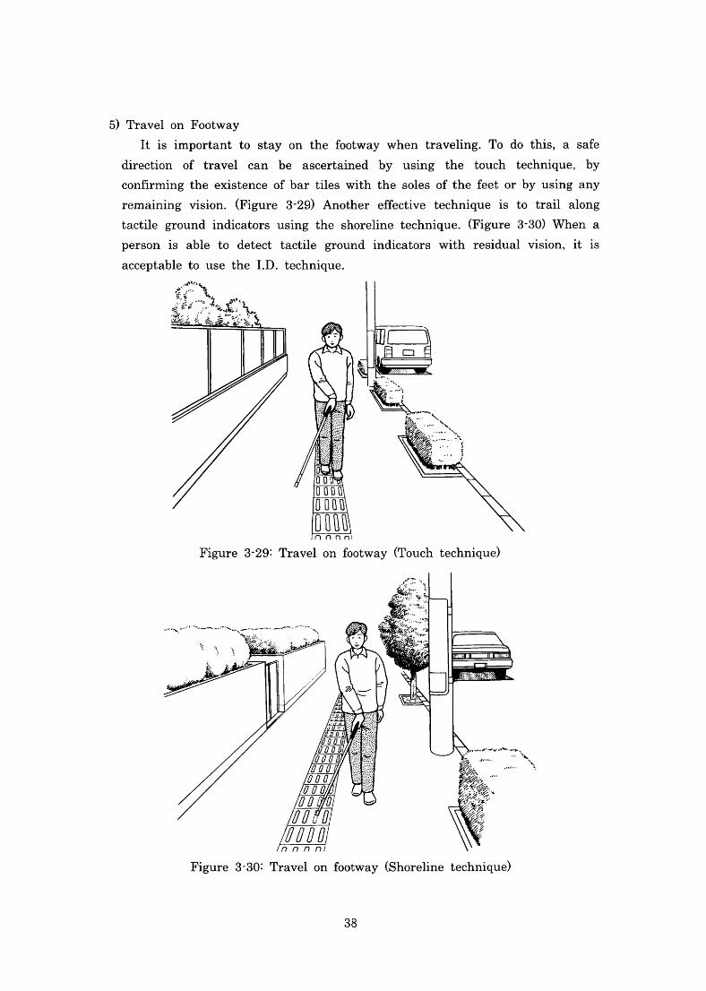
5)Travelon Footway
Itisimportant to stay on thefootway when traveling.To do this,a Safe
direction of travelcan be ascertained by uslng the touch techmique,by
COn艮rming the existence ofbar tiles withthe soles ofthefeet or by using any
remainingvision.(Figure3-29)Another effbctive techniqueis to trailalong
tactile groundindicators using the shoreline technique.(Figure3・30)When a
PerSOnis able to detect tactile groundindicators with residualvision,itis
acceptable to use theI.D.technique.
Figure3-29:Travelon駄)OtWay(Touch technique)
Figure3-30:Travelonfootway(Shoreline technique)
38
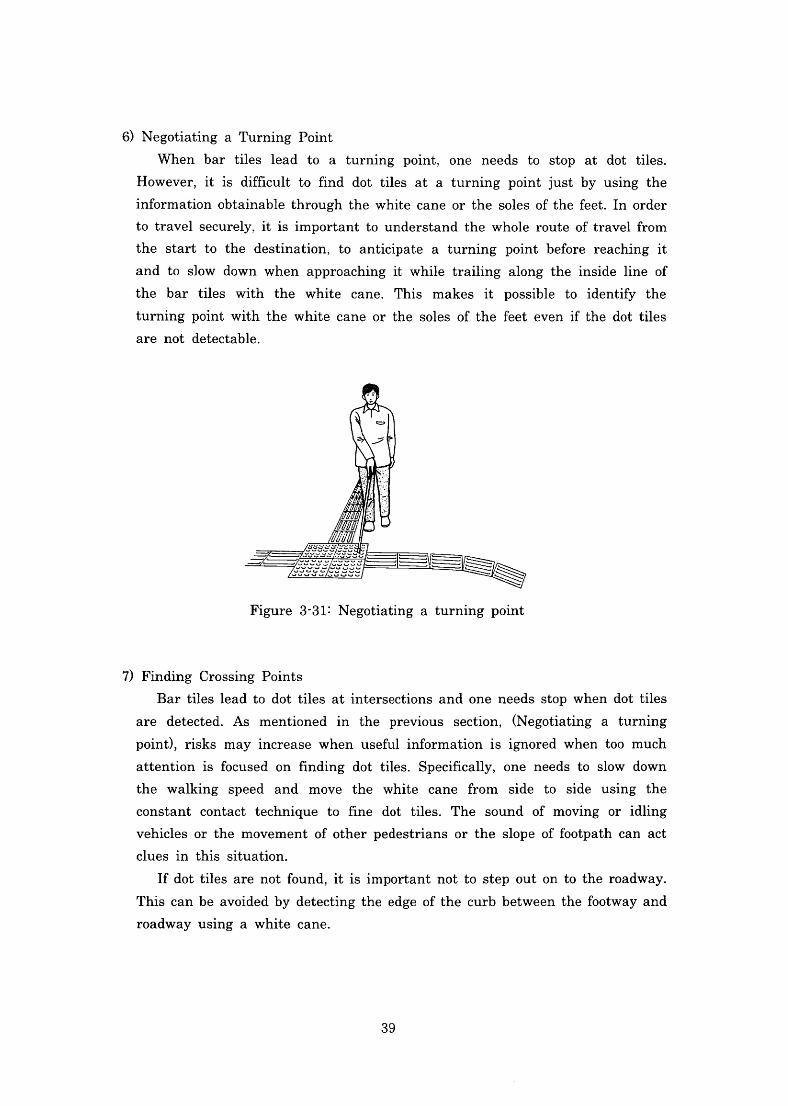
6)Negotiating a TurningPoint
When bar tileslead to a turnlng POint,One needs to stop at dot tiles.
However,itis dimcult to丘nd dot tiles at a turning point just by uslng the
infbrmationobtainable throughthewhite cane orthe soles ofthefbet.Inorder
to travelsecurely,itisimportant tounderstand the whole route oftravelfrom
the start to the destination,tO anticipate a turning point before reachingit
and to slow down when approachingit while trailing along theinsideline of
the bar tiles with the white cane.This makesit possible toidentifythe
turnlng pOint with the white cane or the soles ofthe fbet evenifthe dot tiles
are not detectable.
Figure3-31:Negotiating a turnlng pOint
7)Finding Crossing Points
Bar tileslead to dottiles atintersections and one needs stop when dottiles
are detected.Asmentionedinthe previous section,(Negotiating a turning
point),risks mayincrease when usefu1informationisignored when too much
attentionisfocused onfinding dot tiles.Speci且cally,One needs to slow down
the walking speed and move the white cane from side to side using the
COnStant COntaCt teClmique tofine dot tiles.The sound of moving oridling
Vehicles or the movement ofother pedestrians or the slope offbotpath canaCt
cluesin this situation.
Ifdottiles are notfound,itisimportant not to step outontotheroadway.
Thiscanbe avoidedby detectingthe edge ofthe curb betweenthefootwayand
roadway uslng a White cane.
39
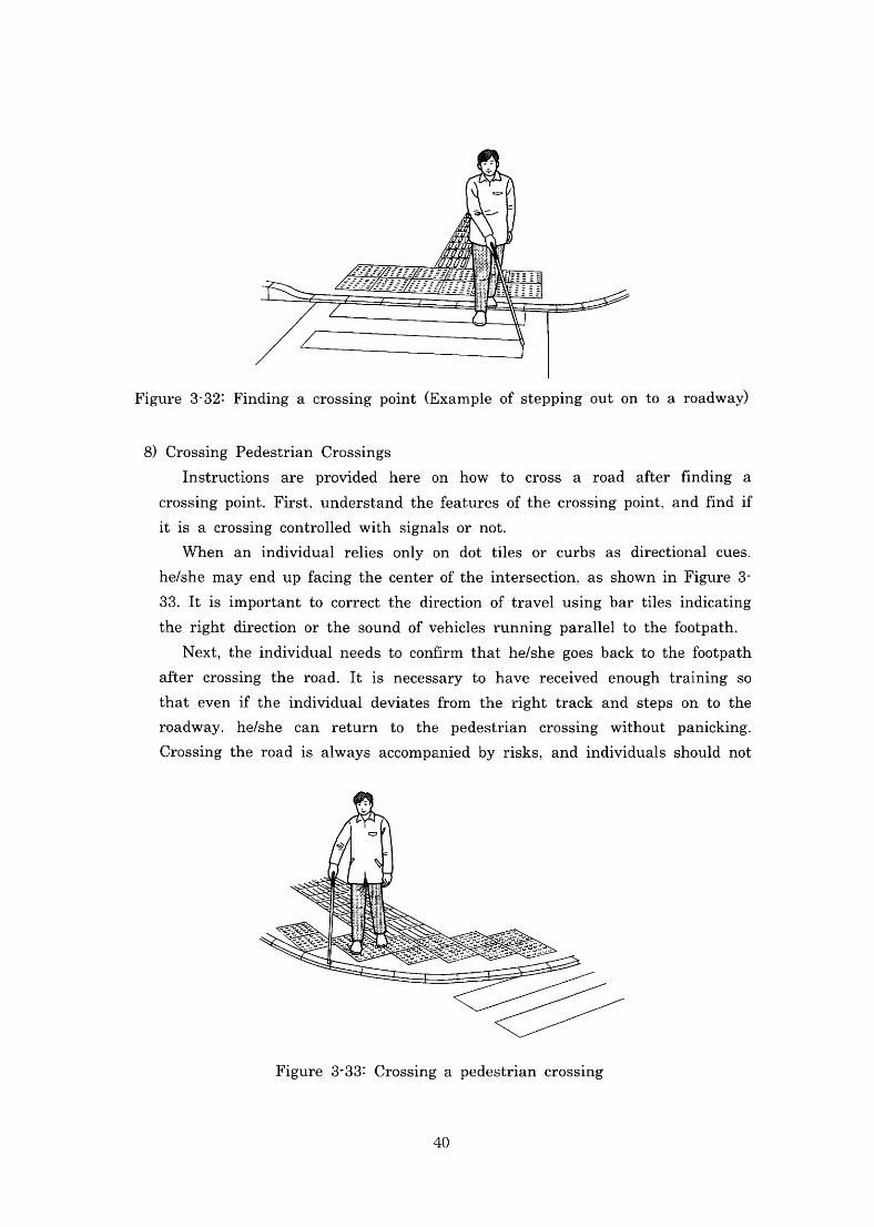
Figure3-32‥Findingacrossingpoint(Exampleofsteppingoutontoaroadway)
8)Crossing Pedestrian Crossings
Instructions are provided here on how to cross a road after丘nding a
crossingpoint・First,underst・andthef6aturesofthecrossingpoint,and丘ndif
itis a crossing controlled with signals or not・
When anindividualrelies only on dot tiles or curbs as directionalcuesl
he′shemayendupfacingthecenteroftheintersection,aSShowninFigure3-
33.Itisimportantto correctthe direction oftravelusingbartilesindicatlng
the rightdirectionorthe soundofvehicles runningparalleltothefbotpath・
Next,theindividualneeds tocon丘rm thathe/she goesbacktothefbotpath
after crosslngthe road.Itis necessary to have received enoughtraining so
that evenif theindividualdeviatesfrom the right track and steps on to the
roadway.he/she can return to the pedestrian crossing without panicking・
Crossingtheroadis always accompaniedbyrisks,andindividuals should not
Figure3-33:Crossing a pedestrian crossing
40
hesitate to ask for help whenever necessary rather than venturing to walk out
OntO the roadalone.
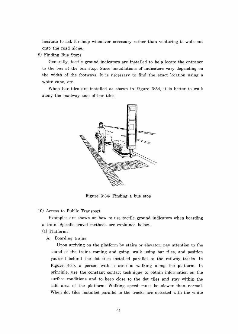
9)FindingBus Stops
Generally,taCtile groundindicators areinsta11ed to helplocate the entrance
to the bus at the bus stop.Sinceinstallations ofindicators vary depending on
thewidth of thefootways,itis necessary to且nd the exactlocation using a
White cane,etC.
When bar tiles areinstalled as shownin Figure3-34,itis better to walk
alongthe roadway side ofbar tiles.
Figure3-34:Finding a bus stop
10)Access to PublicTransport
Examples are shown onhow to usetactile groundindicators whenboarding
a train.Specific travelmethods are explained below.
(1)Platfbrms
A.Boarding trains
Uponarrivingonthe platfbrmbystairs orelevator,Payattentiontothe
SOund ofthe trains comlng and golng,Walk using bar tiles,and position
yourself behind the dot tilesinstalled paralleltothe railway tracks.In
Figure 3-35,a PerSOn With a caneis walking along the platfbrm.In
prlnCiple,uSe the constant contact technique to obtaininformation on the
Surface conditions and to keep close to the dot tiles and stay withinthe
Safearea of the platform.Walking speed must be slower than normal.
When dot tilesinstalled parallelto the tracks are detected with the white
41
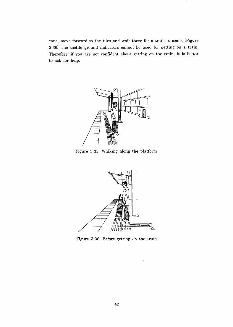
cane,mOVefbrwardtothetilesandwaitthereforatraintocome.(Figure
3-36)The tactile groundindicators cannot be usedfor getting on a train・
Therefbre,ifyou are not conndent about getting on the train,itis better
to ask fbr help.
Figure3-35:Walking along the platform
Figure3-36:Befbre getting onthe train
42
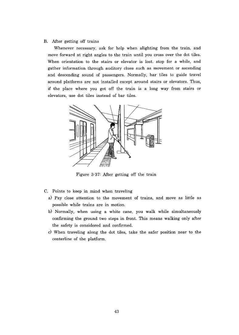
B.After getting offtrains
Whenever necessary,aSkfor help when alighting from the train,and
moveforwardatright angles tothetrainuntilyou cross overthe dottiles.
When orientation to the stairs or elevatorislost,StOpfor a while,and
gather information throwgh auditory clues such as movement or ascending
and descending sound of passengers.Normally,bar tiles to guide travel
aroundplatforms are notinsta11edexcept around stairs or elevators.Thus,
if the place where you get off the trainis along way h・Om Stairs or
elevators,uSe dot tilesinstead ofbar tiles.
Figure3-37:After getting offthe train
C.Points to keepln mind when traveling
a)Pay close attention tothe movement of trains,and move aslittle as
POSSible while trains arein motion.
b)Normally,When using a white cane,yOu Walk while simultaneously
COnnrmingthe groundtwo stepsinfront.This means walkingonlyafter
the safetyis considered and confirmed.
c)When traveling along the dot tiles,takethe safbr position near tothe
Centerline ofthe platfbrm.
43
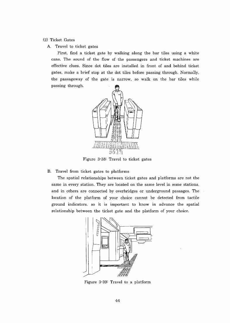
(2)Ticket Gates
A.Travelto ticket gates
First,nnd a ticket gate by walking along the bar tiles uslng a White
cane.The sound of theflow of the passengers and ticket machines are
effective clues.Since dot tiles areinsta11edin丘ont of and behind ticket
gates,make abriefstop atthedottilesbefbrepassingthrough・Normally,
the passageway of the gateis narrow,SO Walk onthe bar tiles while
PaSSing through.
ノ州 1[l Figure3・38:Travelto ticket gates
B.Travelfrom ticket gates to platforms
Thespatialrelationshipsbetweenticketgatesandplatfbrmsarenotthe
sameineverystation・Theyarelocatedonthesamelevelinsomestations,
andin others are connectedby overbridges or undergroundpassages・The
location of the platfbrm of your choice cannot be detected ftom tactile
groundindicators・SOitisimportant toknowin advance the spatial relationship between the ticket gate andtheplatfbrm ofyourchoice・
Figure3-39:Travelto a platform
44
When stairs are used to galn aCCeSS tO a Platform、One muSt be carefu1
not to deviate from the correct route of travel while ascending or
descendingthe stairs.Itisimportant to bearin mindthat there are no
tactile groundindicatorsinstalled on the steps.
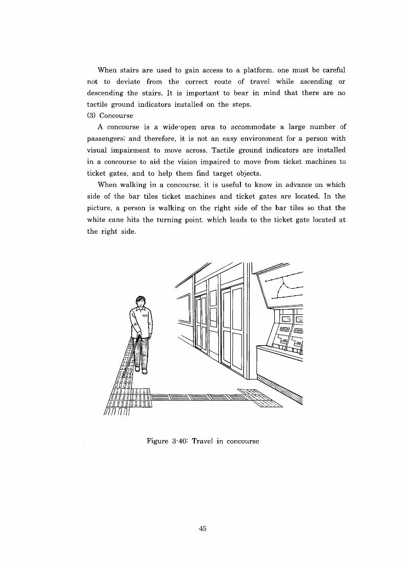
(3)Concourse
A concourseis a wide-OPen area tO aCCOmmOdate alarge number of
passengers;andtherefore,itis not an easy environment for a person with
visualimpalrment tO mOVe aCrOSS.Tactile groundindicators areinstalled
in a concourse to aid thevisionimpaired to movefrom ticket machines to
ticket gates、and to help them丘nd target objects.
When walkingln a COnCOurSe.itis usefu1to knowinadvance on which
Side ofthe bar tiles ticket machines and ticket gates arelocated.In the
picture,a PerSOnis walking on the right side ofthe bar tiles so thatthe
White cane hitstheturnlngPOint,Whichleads tothe t・icket gatelocated at
the right side.
Figure3-40:Travelin concourse
45

References
1.YoichiSakamoto:Outline of Rehabilitation for VisuallyImpaired Persons,
ChuohokiShuppan,2002
2.YuichiShibata,author and editor/SocialAdaptability Trainingfor Visually
Impaired Persons,Nippon Lighthouse,1990
3.JapanRoadAssociation:Guideline andManualofInstallationofTactile Ground
SurfaceIndicatorsfor Blind Persons,1985
46