Embed Size (px)
Citation preview

ACU-T Tactical Interconnect System
Designed and Manufactured by: Raytheon Company 5800 Departure Drive
Raleigh, NC 27616 Email: [email protected]
5030-200200 Revision 1.3
February 2009
II ACU-T OPERATIONS MANUAL
Warranty Raytheon warrants its manufactured equipment to be free from defects in materials and workmanship, and to conform to published specifications for a period of 18 months from the date of shipment from the factory or 12 months from installation, whichever occurs first.
Raytheon warrants its service work performed in connection with this warranty to be free from defects in materials and workmanship for a period of 90 days from the date the work is performed.
If a defect occurs within the warranty period, the buyer shall notify Raytheon immediately. Raytheon will repair or replace the equipment at its option, upon return of the equipment; shipping prepaid, to the Raytheon facility in Raleigh, North Carolina, USA.
This warranty does not apply to damage caused by accidents, abuse or improper installation.
NO OTHER WARRANTY, EXPRESSED OR IMPLIED, INCLUDING BUT NOT LIMITED TO THE IMPLIED WARRANTIES OF MERCHANTABILITY AND FITNESS FOR A PARTICULAR PURPOSE, SHALL APPLY.
NOTICE Raytheon reserves the right to make changes to the equipment and specifications without prior notice.
PROPRIETARY STATEMENT The information contained in this manual is the property of Raytheon and is intended for the purchaser’s use only. It may not be reproduced without the express written consent of Raytheon Company.
Raytheon Phone: (919) 790-1011 Fax: (919) 790-1456 E-mail: [email protected] 5800 Departure Drive Raleigh, NC 27616
ACU-T OPERATIONS MANUAL III
Table of Contents 1 GENERAL INFORMATION............................................................... 1-1
1.1 Scope........................................................................................ 1-1 1.2 Description................................................................................ 1-1
1.2.1 General ............................................................................ 1-1 1.2.2 Card Cage........................................................................ 1-1 1.2.3 Power Supply ................................................................... 1-2 1.2.4 HSP-4 Module.................................................................. 1-3 1.2.5 CPM-2 Module ................................................................. 1-4 1.2.6 DSP-1 Module.................................................................. 1-4 1.2.7 PSTN-1 Module................................................................ 1-4 1.2.8 LP-1 Module..................................................................... 1-5 1.2.9 System Software.............................................................. 1-5 1.2.10 Computer Control Software “ACU Controller” ............. 1-5
1.3 Optional Equipment .................................................................. 1-5 1.3.1 Case Option ..................................................................... 1-5 1.3.2 Radio Interface Cables .................................................... 1-5 1.3.3 AP-1 Options.................................................................... 1-6 1.3.4 RDI-1 Module ................................................................... 1-6 1.3.5 Nextel Interface ................................................................ 1-7 1.3.6 Cell Phone Interfaces....................................................... 1-7
2 INSTALLATION................................................................................. 2-1
2.1 General ..................................................................................... 2-1 2.2 Unpacking and Inspection ........................................................ 2-1 2.3 Reshipment of Equipment ........................................................ 2-2 2.4 Installation Overview................................................................. 2-3 2.5 Installation Considerations........................................................ 2-3
2.5.1 Proper Use of System Antennas...................................... 2-4 2.5.2 Antenna Location and Desensing .................................... 2-4
2.5.2.1 How Desensing Affects the TRP-1000 System........... 2-5 2.5.3 Proper Use of RF Extension Cables ................................ 2-5 2.5.4 Proper Use of Ground Planes.......................................... 2-6 2.5.5 Antenna Options .............................................................. 2-6 2.5.6 Cooling ............................................................................. 2-8
2.6 Power Requirements .............................................................. 2-12 2.6.1 Battery Power for the ACU-T ......................................... 2-13

IV ACU-T OPERATIONS MANUAL
2.6.2 Charge Switch ................................................................2-13 2.6.3 Charger ON LED ............................................................2-13 2.6.4 Reverse Polarity Protection ............................................2-14 2.6.5 Fuse Information.............................................................2-14
2.7 Installation Checklist................................................................2-15 2.8 External Interconnect Information ...........................................2-16
2.8.1 HSP-4 Module Connections ...........................................2-17 2.8.2 DSP-1 Module Connections ...........................................2-18 2.8.3 PSTN-1 Module Connections .........................................2-19 2.8.4 LP-1 Module Connections ..............................................2-20 2.8.5 AP-1 Module Connections..............................................2-21
2.8.5.1 AP-1 Cable Information..............................................2-22 2.8.6 Serial Remote Connector ...............................................2-22
2.9 Hardware Configuration Settings ............................................2-23 2.9.1 CPM-2 Switch Settings...................................................2-26
2.9.1.1 Baud Rate SW1-1 and SW1-2 ...................................2-26 2.9.1.2 Remote Control Enable SW1-3..................................2-27 2.9.1.3 Serial Sync Character SW1-4 ....................................2-27 2.9.1.4 Reserved SW1-5, 6, 7................................................2-28 2.9.1.5 Manufacturing Test SW1-8 ........................................2-28 2.9.1.6 Store Configuration SW2-1 ........................................2-28 2.9.1.7 SW2-2 Through SW2-8..............................................2-28 2.9.1.8 SW3............................................................................2-28
2.9.2 AP-1 Switch Settings ......................................................2-29 2.9.2.1 AP-1 General Information ..........................................2-29 2.9.2.2 Bypass Mode..............................................................2-29 2.9.2.3 AP-1 Digital Delay ......................................................2-30
2.9.2.3.1 AP-1 Digital Delay Setting SW3........................2-30 2.9.2.3.2 Digital Delay Enable AP-1 SW4-1.....................2-30 2.9.2.3.3 Control Signal Delay, AP-1 RX Option..............2-31
2.9.2.3.3.1 Control Signal Delay, AP-1 TX Option ......2-31 2.9.2.4 AP-1 Function Enable Switches, SW4.......................2-31 2.9.2.5 AP-1 Control Tone Generation...................................2-32 2.9.2.6 AP-1 Control Tone Detection .....................................2-32 2.9.2.7 AP-1 Installation Notes...............................................2-33
2.9.3 LP-1 Jumper Settings .....................................................2-34 2.10 Programming Configuration Settings ......................................2-35
2.10.1 To Program a Module: ...............................................2-35 2.11 Programming Configuration Settings ......................................2-49
2.11.1 System Programming and Operating Items..............2-49 2.11.1.1 Enter Programming Mode......................................2-49
ACU-T OPERATIONS MANUAL V
2.11.1.2 Console Override .................................................. 2-49 2.11.1.3 Select a Module to Program.................................. 2-50 2.11.1.4 Exit Programming Mode........................................ 2-50 2.11.1.5 Reset Modules to Factory Settings ....................... 2-50 2.11.1.6 PIN Numbers......................................................... 2-50 2.11.1.7 Program PIN Numbers .......................................... 2-51 2.11.1.8 Delete PIN Numbers ............................................. 2-51 2.11.1.9 Module Security Level Selection ........................... 2-51
2.11.2 HSP-4 Programming Items........................................ 2-51 2.11.2.1 HSP-4 Squelch Type............................................. 2-51
2.11.3 DSP-1 Programming Items........................................ 2-52 2.11.3.1 Receive Level (DSP-1).......................................... 2-52 2.11.3.2 Transmit Level (DSP-1)......................................... 2-53 2.11.3.3 COR Polarity (DSP-1) ........................................... 2-53 2.11.3.4 Full/Half Duplex (DSP-1) ....................................... 2-54 2.11.3.5 DTMF Mute Timer (DSP-1) ................................... 2-54
2.11.3.5.1 Transmitting DTMF via a PSTN Module........... 2-55 2.11.3.5.2 Transmitting DTMF via a Module other than the PSTN-1 2-55
2.11.3.6 COR Type, VOX/VMR Threshold, Hangtime, and Audio Delay (DSP-1) ...................................................................... 2-56
2.11.3.6.1 Receive (Input) Audio Delay............................. 2-59 2.11.3.6.2 Transmit (Output) Audio Delay......................... 2-61
2.11.3.7 Radio Type Selection (DSP-1) .............................. 2-62 2.11.3.8 COR Sampling (DSP-1) ........................................ 2-62
2.11.3.8.1.1 COR Sampling Programming Options: .. 2-63 2.11.3.8.1.2 COR Sampling On/Off ............................ 2-63 2.11.3.8.1.3 Initial Delay Time .................................... 2-63 2.11.3.8.1.4 Sampling Interval.................................... 2-64 2.11.3.8.1.5 Sampling Window Width......................... 2-64
2.11.3.9 Noise Reduction Value (DSP-1)............................ 2-64 2.11.3.10 Audio Muted when Squelched (DSP-1) ................ 2-65 2.11.3.11 Transmit Keying Tones (DSP-1) ........................... 2-65 2.11.3.12 COR Inhibit Time after PTT................................... 2-66 2.11.3.13 PTT or COR Priority (Half Duplex Only)................ 2-66 2.11.3.14 Module Security Level Selection ........................... 2-67 2.11.3.15 DTMF Commands Enable/Disable........................ 2-67 2.11.3.16 High Frequency Equalizer (DSP-1)....................... 2-68 2.11.3.17 DTMF Pre-emphasis ............................................. 2-68 2.11.3.18 Auxiliary Output Control ........................................ 2-69 2.11.3.19 Voice Prompt Initiation Delay ................................ 2-69
2.11.4 PSTN-1 Programming Items ..................................... 2-70 2.11.4.1 Telephone Line Level ............................................ 2-70

VI ACU-T OPERATIONS MANUAL
2.11.4.2 Telephone Receive Level Boost ............................2-70 2.11.4.3 PSTN Type ............................................................2-70 2.11.4.4 Dial Mode...............................................................2-71 2.11.4.5 DTMF Mute Timer..................................................2-71 2.11.4.6 RX Audio Delay......................................................2-72 2.11.4.7 VOX Threshold ......................................................2-72 2.11.4.8 VOX Hangtime .......................................................2-73 2.11.4.9 2-Wire/4-Wire Operation (STU-III Operation) ........2-73 2.11.4.10 Module Security Level Selection............................2-73 2.11.4.11 Outgoing Ring Timer..............................................2-74 2.11.4.12 DTMF Command Enable .......................................2-74 2.11.4.13 Auxiliary Output Control .........................................2-74 2.11.4.14 Inactivity Disconnect Timer....................................2-75 2.11.4.15 Voice Prompt Initiation Delay.................................2-75 2.11.4.16 PSTN-1 Simplified Setup Procedure .....................2-75
2.11.5 LP-1 Programming Items ...........................................2-77 2.11.5.1 DTMF Mute Timer..................................................2-77
2.11.5.1.1 Transmitting DTMF via a PSTN Module ...........2-78 2.11.5.1.2 Transmitting DTMF via a Module other than the PSTN-1 2-78
2.11.5.2 RX Audio Delay......................................................2-79 2.11.5.3 VOX Threshold ......................................................2-79 2.11.5.4 VOX Hangtime .......................................................2-79 2.11.5.5 Module Security Level Selection............................2-79 2.11.5.6 Dial & Busy Tone Style ..........................................2-80 2.11.5.7 Ring Cadence ........................................................2-80 2.11.5.8 Dial Tone Enable ...................................................2-80 2.11.5.9 Ringback Enable....................................................2-80 2.11.5.10 Outgoing Ring Timer..............................................2-81 2.11.5.11 DTMF Command Enable .......................................2-81 2.11.5.12 Aux Output Control ................................................2-81 2.11.5.13 Voice Prompt Initiation Delay.................................2-82
3 OPERATION ......................................................................................3-1
3.1 General......................................................................................3-1 3.2 Front And Top Panel Controls and Indicators...........................3-1
3.2.1 Power ON LED (Top Panel) .............................................3-2 3.2.2 Charger ON LED (Top Panel) ..........................................3-2 3.2.3 System Connection Status Display (Top Panel) .............3-2 3.2.4 Speaker Switch (Top Panel).............................................3-2 3.2.5 Headphones Output Jack (HSP-4 Front Panel) ..............3-2 3.2.6 Volume Control (Top Panel) .............................................3-3

ACU-T OPERATIONS MANUAL VII
3.2.7 Fault LEDs (HSP-4, DSP-1, PSTN-1, LP-1) .................... 3-3 3.2.8 Master/Slave LEDs (CPM-2)............................................ 3-3 3.2.9 Mon (Monitor) LED (DSP-1, PSTN-1, LP-1) .................... 3-3 3.2.10 Signal LED (DSP-1)..................................................... 3-3 3.2.11 PTT LED (DSP-1), VOX LED (PSTN-1, LP-1) ........... 3-3 3.2.12 COR LED (DSP-1)....................................................... 3-4 3.2.13 Ring LED (PSTN-1, LP-1)............................................ 3-4 3.2.14 Connect LED (PSTN-1) ............................................... 3-4 3.2.15 Off-hook LED (LP-1) .................................................... 3-4
3.3 Rear and Side Panel Connectors ............................................. 3-5 3.4 Basic Chassis Modules - Functions and Operation................. 3-5
3.4.1 CPM-2 .............................................................................. 3-5 3.4.2 HSP-4............................................................................... 3-6
3.4.2.1 Make a Connection...................................................... 3-8 3.4.2.2 Break a Connection ..................................................... 3-9 3.4.2.3 Attention Command..................................................... 3-9 3.4.2.4 Report Connections ..................................................... 3-9 3.4.2.5 Disconnect Another Extension .................................... 3-9 3.4.2.6 Monitor Function ........................................................ 3-10 3.4.2.7 Store Connection Table in Memory ........................... 3-10 3.4.2.8 Regain Control from Console Program ..................... 3-11 3.4.2.9 Data / Command Modes............................................ 3-11 3.4.2.10 System Reset Feature........................................... 3-12
3.4.3 Use of Radio at HSP Connector J0 ............................... 3-12 3.5 Interface Modules – Functions and Operation........................ 3-14
3.5.1 DSP-1............................................................................. 3-15 3.5.2 PSTN-1 .......................................................................... 3-15 3.5.3 LP-1................................................................................ 3-16 3.5.4 AP-1 ............................................................................... 3-16 3.5.5 Interface Module Operational Commands ..................... 3-17
3.5.5.1 Make a Connection.................................................... 3-18 3.5.5.2 Break a Connection ................................................... 3-18 3.5.5.3 Attention Command................................................... 3-19 3.5.5.4 Monitor Function ........................................................ 3-19 3.5.5.5 Data / Command Modes............................................ 3-19 3.5.5.6 System Reset Feature ............................................... 3-20
3.6 PIN Security ............................................................................ 3-21 3.6.1 How PIN Security Works................................................ 3-21 3.6.2 PIN Security Modes ....................................................... 3-22
3.6.2.1 Priority Operation Mode............................................. 3-22 3.6.2.2 Exclusive Operation Mode......................................... 3-22
3.6.3 How to enable PIN Security ........................................... 3-22

VIII ACU-T OPERATIONS MANUAL
3.6.4 How to Set ACU-T Security Levels ................................3-23 3.6.5 How to Input PIN Numbers into the ACU-T Database ...3-23 3.6.6 How to Delete PIN Numbers from the Database............3-24 3.6.7 How To Use The Pin Security Feature...........................3-24
3.7 ACU-T Operation.....................................................................3-25 3.7.1 Unit Power-Up ................................................................3-25 3.7.2 Basic Operation Scenarios .............................................3-26
3.7.2.1 Radio to Radio............................................................3-27 3.7.2.1.1 Conditions: ........................................................3-27 3.7.2.1.2 Operation Steps: ...............................................3-27
3.7.2.2 PSTN to Radio ...........................................................3-28 3.7.2.2.1 Conditions: ........................................................3-28 3.7.2.2.2 Operation Steps: ...............................................3-28
3.7.2.3 Local Operator to Radio .............................................3-29 3.7.2.3.1 Conditions: ........................................................3-29 3.7.2.3.2 Operation Steps: ...............................................3-29
3.7.2.4 Radio to Local Operator .............................................3-29 3.7.2.4.1 Conditions: ........................................................3-29 3.7.2.4.2 Operation Steps: ...............................................3-29
3.7.2.5 Radio to PSTN ...........................................................3-31 3.7.2.5.1 Conditions: ........................................................3-31 3.7.2.5.2 Operation Steps: ...............................................3-31
3.7.2.6 Local Phone to Radio.................................................3-32 3.7.2.6.1 Conditions: ........................................................3-32 3.7.2.6.2 Operation Steps: ...............................................3-32
3.7.2.7 Conference Call..........................................................3-33 3.7.2.7.1 Conditions: ........................................................3-33 3.7.2.7.2 Operation Steps: ...............................................3-33
3.8 SERIAL Remote Control (RS-232)............................................3-35 3.9 Removal and Replacement of Modules ..................................3-35 4 ACU-T TECHNICAL INFORMATION................................................4-1
4.1 Scope ........................................................................................4-1 4.2 General Description...................................................................4-1 4.3 Card Cage and Backplane ........................................................4-1 4.4 CPM-2 Control Processor Module ............................................4-2 4.5 HSP-4 Handset/Speaker Module ..............................................4-3
4.5.1 General Description HSP-4 ..............................................4-3 4.5.2 Block Diagram Description HSP-4 ...................................4-4 4.5.3 HSP-4 Specifications........................................................4-6

ACU-T OPERATIONS MANUAL IX
4.6 DSP-1 Module .......................................................................... 4-8 4.6.1 General Description DSP-1.............................................. 4-8 4.6.2 Block Diagram Description DSP-1 ................................... 4-8 4.6.3 DSP-1 Specifications ..................................................... 4-10
4.7 PSTN-1 Module ...................................................................... 4-12 4.7.1 General Description PSTN-1 ......................................... 4-12 4.7.2 Block Diagram Description PSTN-1............................... 4-12 4.7.3 PSTN-1 Specifications ................................................... 4-15
4.8 LP-1 Module ........................................................................... 4-17 4.8.1 General Description LP-1............................................... 4-17 4.8.2 Block Diagram Description LP-1 .................................... 4-17 4.8.3 LP-1 Specifications ........................................................ 4-19
4.9 AP-1 Module ........................................................................... 4-21 4.9.1 AP-1 General Description .............................................. 4-21 4.9.2 Block Diagram Description............................................. 4-22 4.9.3 AP-1 Specifications........................................................ 4-23
5 OPTIONS........................................................................................... 5-1
5.1 STU-III Option........................................................................... 5-1 5.1.1 Equipment Required ........................................................ 5-1 5.1.2 Application........................................................................ 5-1 5.1.3 Installation ........................................................................ 5-2
5.1.3.1 Connecting the STU-III phone to the ACU-T............... 5-2 5.1.3.2 ACU-T Alignment for STU-III ....................................... 5-4
5.1.4 Operation: Cross Connecting a STU-III phone ............... 5-5 6 INDEX 6-1

X ACU-T OPERATIONS MANUAL
LIST OF FIGURES
FIGURE 2-1 FRONT PANEL VIEW........................................................2-9 FIGURE 2-2 TOP PANEL VIEW..........................................................2-10 FIGURE 2-3 REAR PANEL VIEW .......................................................2-11 FIGURE 3-1 PICTORIAL LAYOUT FOR OPERATING SCENARIOS ...........3-26 FIGURE 3-2 CONNECTION STATUS #1 ..............................................3-27 FIGURE 3-3 CONNECTION STATUS #2 ..............................................3-28 FIGURE 3-4 CONNECTION STATUS #3 ..............................................3-30 FIGURE 3-5 CONNECTION STATUS #4 ..............................................3-32 FIGURE 4-1 HSP-4 BLOCK DIAGRAM..ERROR! BOOKMARK NOT DEFINED. FIGURE 4-2 DSP-1 BLOCK DIAGRAM..ERROR! BOOKMARK NOT DEFINED. FIGURE 4-3 PSTN-1 BLOCK DIAGRAMERROR! BOOKMARK NOT DEFINED. FIGURE 4-4 LP-1 BLOCK DIAGRAM.....ERROR! BOOKMARK NOT DEFINED. FIGURE 4-5 AP-1 BLOCK DIAGRAM ....ERROR! BOOKMARK NOT DEFINED.

ACU-T OPERATIONS MANUAL XI
LIST OF TABLES
TABLE 1-1 GENERAL SPECIFICATIONS ................................................. 1-8 TABLE 1-3 EQUIPMENT AND ACCESSORIES SUPPLIED........................... 1-9 TABLE 1-5 INTERFACE MODULES ....................................................... 1-10 TABLE 1-7 OPTIONAL EQUIPMENT - NOT SUPPLIED............................ 1-11 TABLE 2-1 ACU-T FUSES ................................................................. 2-14 TABLE 2-3 INSTALLATION CHECKLIST................................................. 2-15 TABLE 2-5 CHASSIS SLOTS, EXTENSIONS, CONNECTORS, AND MODULES2-17 TABLE 2-7 HSP-4 MODULE CONNECTIONS- J0 .................................. 2-17 TABLE 2-9 DSP-1 MODULE CONNECTIONS- J1 THROUGH J5 ............. 2-18 TABLE 2-11 PSTN-1 MODULE CONNECTIONS- J1 THROUGH J5....... 2-19 TABLE 2-13 LP-1 MODULE CONNECTIONS- J1 THROUGH J5............. 2-20 TABLE 2-15 AP-1 MODULE CONNECTIONS- J1 THROUGH J5 ............ 2-21 TABLE 2-17 SERIAL REMOTE CONNECTIONS- J10............................ 2-22 TABLE 2-20 ACU-T HARDWARE CONFIGURATION SETTINGS ............ 2-24 TABLE 2-22 BAUD RATE ................................................................. 2-26 TABLE 2-24 REMOTE CONTROL ENABLE.......................................... 2-27 TABLE 2-26 SERIAL SYNC CHARACTER ........................................... 2-27 TABLE 2-28 MANUFACTURING TEST ................................................ 2-28 TABLE 2-30 STORE CONFIGURATION............................................... 2-28 TABLE 2-32 AP-1 DIGITAL DELAY SETTINGS, SW3 .......................... 2-30 TABLE 2-35 AP-1 DSP FUNCTION ENABLE, SW4 ............................ 2-32 TABLE 2-36 JUMPER SETTINGS LP-1 .............................................. 2-34 TABLE 2-38 ACU-T CONFIGURATION PROGRAMMING ITEMS ................... 2-38 TABLE 3-1 HSP-4 OPERATIONAL COMMAND ITEMS .............................. 3-7 TABLE 3-3 OPERATIONAL COMMANDS............................................... 3-17 TABLE 4-1 HSP-4 SPECIFICATIONS ..................................................... 4-6 TABLE 4-3 DSP-1 SPECIFICATIONS ................................................... 4-10 TABLE 4-5 PSTN-1 SPECIFICATIONS ................................................. 4-15 TABLE 4-7 LP-1 SPECIFICATIONS ...................................................... 4-19 TABLE 4-9 AP-1 SPECIFICATIONS...................................................... 4-23
XII ACU-T OPERATIONS MANUAL
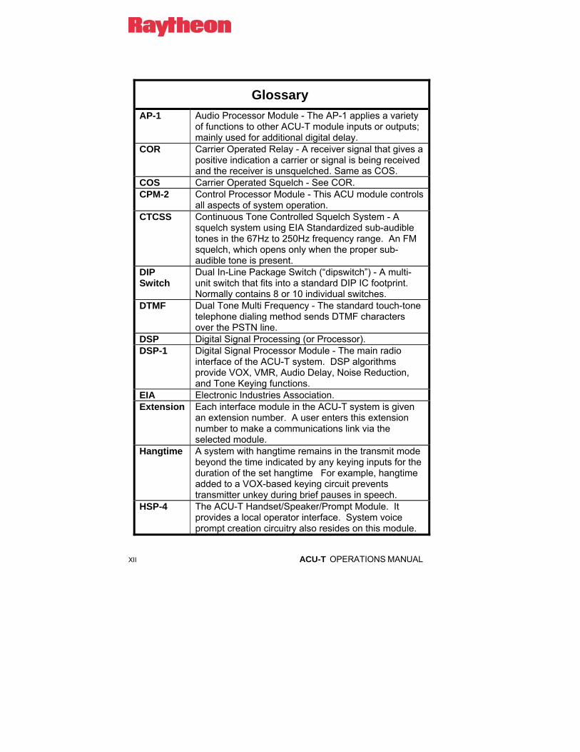
Glossary AP-1 Audio Processor Module - The AP-1 applies a variety
of functions to other ACU-T module inputs or outputs; mainly used for additional digital delay.
COR Carrier Operated Relay - A receiver signal that gives a positive indication a carrier or signal is being received and the receiver is unsquelched. Same as COS.
COS Carrier Operated Squelch - See COR. CPM-2 Control Processor Module - This ACU module controls
all aspects of system operation. CTCSS Continuous Tone Controlled Squelch System - A
squelch system using EIA Standardized sub-audible tones in the 67Hz to 250Hz frequency range. An FM squelch, which opens only when the proper sub-audible tone is present.
DIP Switch
Dual In-Line Package Switch (“dipswitch”) - A multi-unit switch that fits into a standard DIP IC footprint. Normally contains 8 or 10 individual switches.
DTMF Dual Tone Multi Frequency - The standard touch-tone telephone dialing method sends DTMF characters over the PSTN line.
DSP Digital Signal Processing (or Processor). DSP-1 Digital Signal Processor Module - The main radio
interface of the ACU-T system. DSP algorithms provide VOX, VMR, Audio Delay, Noise Reduction, and Tone Keying functions.
EIA Electronic Industries Association. Extension Each interface module in the ACU-T system is given
an extension number. A user enters this extension number to make a communications link via the selected module.
Hangtime A system with hangtime remains in the transmit mode beyond the time indicated by any keying inputs for the duration of the set hangtime For example, hangtime added to a VOX-based keying circuit prevents transmitter unkey during brief pauses in speech.
HSP-4 The ACU-T Handset/Speaker/Prompt Module. It provides a local operator interface. System voice prompt creation circuitry also resides on this module.

ACU-T OPERATIONS MANUAL XIII
Glossary Key To key a transmitter means to cause it to transmit. LED Light Emitting Diode. LMR Land Mobile Radio. LP-1 The Local Phone Module in the ACU-T system. Mute To quiet or inhibit audio. PCB Printed Circuit Board. Port The ACU-T side panel connectors J0 through J5
provide Communications Ports to interface with other communications equipment.
PTT Push-to-Talk - An active PTT signal causes a transmitter to key.
RX Receiver or Receiving. Slot A physical location in the ACU-T chassis where a
module can be inserted. SNR Signal-to-Noise Ratio. Squelch A means of detecting audio and causing some action
when it is present, such as muting an audio path. TX Transmit or Transmitter. VMR Voice Modulation Recognition - A type of squelch,
which is activated only by spoken words and not by tones, noise, or other audio information.
VOX Voice Operated Xmit (Transmit) - A circuit or algorithm, which causes a transmitter to key or some other action when voice is present. This squelch type is activated by any audio signal, and is not restricted to voice only.
PSTN-1 The ACU-T module to interface to the Public Service Telephone Network

XIV ACU-T OPERATIONS MANUAL
Blank Page

ACU-T OPERATIONS MANUAL 1-1
1 General Information
1.1 Scope This instruction manual provides the information necessary to install, configure and operate the ACU-T Intelligent Interconnect System.
1.2 Description
1.2.1 General Raytheon’s ACU-T is a tactical modular interface/interconnect system packaged in a Eurocard chassis. With this product, an intelligent interconnect system can be configured to meet almost any interface application involving telephones and radios of any sort. The ACU-T is suitable for HF, LMR, and Inmarsat Satcom systems and offers essentially unlimited applications and expandability. A system consists of a chassis, backplane and modules, module software, and system control software.
1.2.2 Card Cage The Card Cage is a 6 1/2" wide transportable unit equipped with a front mount Eurocard cage. Modules are plugged into an internal blackplane via the front panel. The top of the unit is drip-proof to prevent damage from water entry. The module PC Boards are 100 x 220 mm. The card cage height is 6.7” tall, 6.5” wide, with a depth of 11". The power supply assembly is located on the unit’s rear panel and contains the main power switch, fuseholder, battery charger switch, and power input connectors. The ACU-T interfaces with the radios and other devices via side-mounted quick-lock circular connectors.

1-2 ACU-T OPERATIONS MANUAL
1.2.3 Power Supply The Power Supply is a single PC board assembly mounted to the unit's rear panel. The supply accepts input voltages ranging from +9V to +16V DC and furnishes all of the internal voltages required for the ACU-T to operate. The supply also has an internal battery charger with a 1A tapered charge characteristic designed for 12V gel-cell batteries.
There are two isolated power inputs. Input J7 is designed to accept +15VDC from an AC adaptor (included with the unit) and will power both the ACU-T and the battery charger. Inputs J8 and J9 (wired in parallel; not isolated from each other) accept nominal 12V battery power.
A system battery will be charged if:
• The AC adapter is connected to J7 (and supplying power)
• A 12V battery is connected to either J8 or J9
• The battery charger switch is set to on
If the AC line voltage fails or the adapter is unplugged from J7, the battery will automatically take over the power supply to the unit.
Two battery inputs (J8 and J9) are provided so that a fresh battery may be connected to the unit without momentarily causing the ACU-T to lose power during a battery change.
The only requirement for +15VDC at J7 is to operate the battery charger. If the charger is not needed, any voltage as low as +9VDC will power the unit from J7.

ACU-T OPERATIONS MANUAL 1-3
1.2.4 HSP-4 Module The HSP-4 Module provides circuitry to locally monitor, configure and control an ACU-T system. The user can monitor audio via the top-mounted internal speaker (or plug in an external speaker). Alternatively, the set of headphones or the handset that comes with the HSP-4 can be used. The handset includes a PTT switch to allow the user to key a cross-connected radio via the HSP-4. Module control and configuration is made via a 3x4 keypad (standard telephone layout) on the top panel of the ACU-T. For example, if the system contains a PSTN-1 module, the user may place telephone calls manually using the HSP-4 keypad and handset. The HSP-4 may also be used to set configuration parameters (input and output levels, for example) of all system modules.
The handset and headphone jacks are mounted on the front panel of the HSP-4, and all of its other controls are mounted on the top of the ACU-T. These include: the speaker, speaker On/Off switch, volume control, keypad, and system connection status display. All system voice prompt circuitry resides on the HSP-4.
The System Connection Status display is a three row by six column matrix of 18 LED indicators. The rows designate Connection Nets 1, 2, and 3, while the columns indicate modules that may be interconnected in these nets: the HSP-4 and the five (max) other extension modules in the chassis. As connections are made between modules, the LEDs at the appropriate intersections light, indicating which modules are connected together in what nets. When the ACU-T powers up, the status display flashes each of the six columns left-to-right as a display test and indication of proper initialization.
The HSP-4 can also act as an extra radio port for the ACU-T if its local handset function is not required. In this case, a radio is plugged into the J0 connector on the side of the unit. This connector interfaces with the HSP-4 and provides audio I/O as well as a VOX function plus COR and PTT signals.

1-4 ACU-T OPERATIONS MANUAL
1.2.5 CPM-2 Module The CPM-2 Control Processor Module controls the entire chassis via an internal high-speed serial bus; it requests and receives status and information from each module and sends commands to each module. It instructs modules to output their audio to one of the system audio buses. The CPM-2 provides an RS-232 serial port allowing programming and monitoring of all ACU-T functions via an external computer or serially interfaced console connected to J10 on the rear panel. The front panel of the CPM-2 Module contains a Fault LED (the front panel Master and Slave LEDs are non-functional in an ACU-T).
1.2.6 DSP-1 Module This module is the main interface module for radios and other 4-wire devices. It contains circuits to interface balanced or unbalanced audio from a receiver and to a transmitter, and has level adjustments for both. The DSP-1 contains three types of COR (receiver unsquelched condition detection); hardwired signal, VMR, and VOX. It offers a DSP noise reduction mode. The VMR and Noise Reduction capability make it ideal for an HF radio interface. Other features include audio delay, configurable equalization of RX input, and key tone capability.
1.2.7 PSTN-1 Module The PSTN Module is the 2-wire interface between the ACU system and a telephone system (as opposed to a telephone set). A telephone system is an entity that accepts dialing information and processes calls, such as a PSTN line, PABX line, Inmarsat Terminal, or cellular phone. (A telephone set is a device that generates dialing information. It is interfaced to the ACU system via the LP-1 Module.) The PSTN-1 contains one 4-wire port for interfacing to 4-wire phone lines or other devices, and two 2-wire ports with front-panel RJ-11C jacks for interfacing with PSTN lines or satellite equipment. The module contains ring detect circuitry for automated system operation. The interface signal levels are configurable via the HSP-4 module.
The module has a DSP hybrid and VOX with configurable sensitivity and hangtime. It has a DTMF receiver/generator for control and call progress recognition. There are two uncommitted auxiliary parallel inputs and two uncommitted auxiliary parallel outputs. The two 2-wire ports are permanently connected to front-panel RJ-11C jacks.

ACU-T OPERATIONS MANUAL 1-5
1.2.8 LP-1 Module The Local Phone Module is the interface to the ACU system for 2-wire devices that generate dialing information such as a telephone set or FAX machine. This module contains a loop current generator, ring voltage generator, dial and busy tone generators, a DSP hybrid with VOX and a DTMF generator/receiver. In addition to interfacing a telephone set into the ACU system, this module can be used as a telephone "line card" in a mini-PBX system.
1.2.9 System Software This high level software resides on the CPM-2 Control Processor Module and controls all aspects of the ACU-T's inter-operation with the outside world. It contains the interface protocol necessary for external computer control of specific ACU-T Systems, and determines various aspects of the operator's control interface with an ACU-T System, including the timing of the system voice prompts.
1.2.10 Computer Control Software “ACU Controller”
The ACU Controller allows a PC User to control the ACU-T and monitor its status. The ACU Controller is also the easiest way to set or check all of the configuration parameters of the system interface modules.
1.3 Optional Equipment
1.3.1 Case Option The ACU-T case option includes a ruggedized foam-lined carrying case that includes the ACU-T Battery Power Option. The case holds the ACU-T with spaces for its manual, AC power adapter, and accessory kit, plus room for power cables and radio interface cables.
1.3.2 Radio Interface Cables Raytheon offers a variety of cables that interface common radios (both mobile & portable) via the ACU-T’s side-panel CPC connectors. If a cable is required for a radio that Raytheon does not currently interface, Raytheon may create an interface cable design (under certain conditions). Contact Raytheon for further information.

1-6 ACU-T OPERATIONS MANUAL
1.3.3 AP-1 Options The AP-1 module is a general-purpose 4-wire module that can provide a variety of DSP operations. Unlike other ACU-T modules, the AP-1 does not communicate with the system audio and control bus structures on the ACU-T backplane. The AP-1 is “In Series” with the audio signal that is routed through it via the associated CPC connector. The ACU-T chassis provides DC power and a mounting slot for the AP-1.
The DSP functions of the AP-1 can operate either on the audio and control signal coming into the ACU-T module that it is associated with (AP-1 RX Option Assembly), or on the audio and control signal that is exiting the associated ACU-T module (AP-1 TX Option Assembly). The RX and TX options include the required cabling. For example, if the AP-1 TX option is being used to add digital delay to the output audio from a DSP-1 module to the associated radio, The “Y” cable allows the module to be placed in series with the DSP-1’s TX audio.
To use, simply remove the radio interface cable from the side-panel conector associated with the DSP-1 module. Install the AP-1 module into an adjacent chassis slot. Now connect the “Y” cable to the unit: P1 connects to the DSP-1 module, P3 connects to the AP-1 module, and the radio interface connector that had been removed from the ACU-T is now reconnected to P2 of the AP-1 “Y” cable.
Alternatively, the AP-1’s DSP features can be used to modify signals not associated at all with the ACU-T. In this case, the customer can manufacture custom cabling to suit the application.
See Table 2-8 for the AP-1 pinouts for connectors J1 to J5.
1.3.4 RDI-1 Module The RDI-1 module can be used as a basic four-wire interface module. It supports PTT output and COR input, but does not have Digital Signal Processing circuitry and therefore can not perform the sophisticated DSP algorithms that the DSP-1 module can (VMR, VOX, Digital Audio Delay, Tone Keying, etc.). The RDI-1 has one feature that the DSP-1 module does not - an RS-232 interface. Consult Raytheon for any systems that require an RS-232 interface to a connected four-wire device.
ACU-T OPERATIONS MANUAL 1-7
1.3.5 Nextel Interface Raytheon has interface cables to connect to a variety of Nextel Radios. Consult us for details.
1.3.6 Cell Phone Interfaces Raytheon offers some cell-phone cradles that allow commercial cell-phones to be connected into the system via the PSTN-1 module. Consult us for details.
1-8 ACU-T OPERATIONS MANUAL
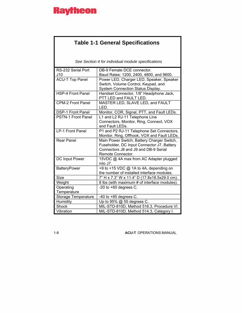
Table 1-1 General Specifications
See Section 4 for individual module specifications
RS-232 Serial Port J10
DB-9 Female DCE connector. Baud Rates: 1200, 2400, 4800, and 9600.
ACU-T Top Panel Power LED, Charger LED, Speaker, Speaker Switch, Volume Control, Keypad, and System Connection Status Display.
HSP-4 Front Panel Handset Connector, 1/8” Headphone Jack, PTT LED and FAULT LED.
CPM-2 Front Panel MASTER LED, SLAVE LED, and FAULT LED.
DSP-1 Front Panel Monitor, COR, Signal, PTT, and Fault LEDs. PSTN-1 Front Panel L1 and L2 RJ-11 Telephone Line
Connectors, Monitor, Ring, Connect, VOX and Fault LEDs.
LP-1 Front Panel P1 and P2 RJ-11 Telephone Set Connectors, Monitor, Ring, Offhook, VOX and Fault LEDs.
Rear Panel Main Power Switch, Battery Charger Switch, Fuseholder, DC Input Connector J7, Battery Connectors J8 and J9 and DB-9 Serial Remote Connector.
DC Input Power 15VDC @ 4A max from AC Adapter plugged into J7.
BatteryPower +9 to +15 VDC @ 1A to 4A, depending on the number of installed interface modules.
Size 7” H x 7.3” W x 11.4” D (17.8x18.5x29.0 cm). Weight 8 lbs (with maximum # of interface modules). Operating Temperature
-20 to +60 degrees C.
Storage Temperature -40 to +85 degrees C. Humidity Up to 95% @ 55 degrees C. Shock MIL-STD-810D, Method 516.3, Procedure VI. Vibration MIL-STD-810D, Method 514.3, Category I.

ACU-T OPERATIONS MANUAL 1-9
Table 1-2 Equipment and Accessories Supplied
Quantity Item P/N
1 ACU-T Chassis An ACU-T system consists of a chassis, HSP-4 and CPM-2 modules, up to 5 Interface Modules (See Table 1-3) in any combination. Unused slots on the chassis are covered with blank plates.
5030-200000
1 HSP-4 Module 5030-202000 1 CPM-2 Module 5961-213000 1 ACU Controller Software 5961-298000 1 Operation & Maintenance Manual 5030-200200 1 Accessory Kit
Consisting of: 5030-200150
Qty Part Number Description 1 0313-037770 Line Cord 1 5030-273000 Power Supply AC Line to 15VDC 4A 1 2010-200350 Screwdriver 1 0313-080000 RS-232 Cable 1 5030-200151 Mounting Brackets, set of 2 2 0650-005250 Fuse, 3AG, 5A, FB, 250V, (F1) 1 0150-200000 Handset with PTT switch, Black 1 0313-060000 Cord, coiled, 5 ft, black, for handset 6 0362-005003 Connector, CPC, Plug 6 0362-005005 Connector, CPC, Cable Shell clamp 54 0362-005002 Connector Sockets, Amp CPC 1 5030-200153 ACU-T Universal Battery Cable 1 5030-200154 ACU-T Aux Power Cable 1 5951-707000 Extender Card Assembly
Note: Connector components and pins allow the user to create ACU-T interface cables. Alternatively, cables may be purchased from Raytheon. See Table 1-4.

1-10 ACU-T OPERATIONS MANUAL
Table 1-3 Interface Modules Item P/N
As Required
DSP-1 Module Main Interface module for connecting radios and other 4-wire devices.
5961-818000
A/R PSTN-1 Module Interface module for connecting to the PSTN, SATCOM Terminal, Cellular Phone or other similar 2-wire devices.
5961-215000
A/R LP-1 Module Interface module for connecting to 2-wire devices such as a local telephone set or FAX machine.
5961-207000

ACU-T OPERATIONS MANUAL 1-11
Table 1-4 Optional Equipment - Not Supplied
Item P/N Description
Spare Parts Kit 5030-293000 Spare Parts Depot Spares Kit
5030-291000 Depot Spares
Battery Power Option Kit
5030-205000 Battery and Cabling
Case Option 5030-204000 Ruggedized foam-lined case includes Battery Power Kit. Has storage spaces for ACU-T accessories and some radio interface cables.
Dual Band Antenna
0130-003002 Antenna, Dual Band, ¼ Wave, 150-512 MHz (trim to tune) Type N Female connector
RF Extension Cable
0314-000009 RF Extension Cable, 25 Feet, has type “N” RF connectors
Computer 5961-300600 Computer, Laptop (for control of ACU-1000
AP-1 RX Option For ACU-T
5961-284001 “Y” cable to place the AP-1 module in series with input (RX) audio.
AP-1 TX Option For ACU-T
5961-284002 “Y” cable to place the AP-1 module in series with output (TX) audio.
1-12 ACU-T OPERATIONS MANUAL
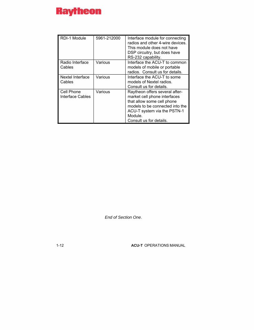
RDI-1 Module 5961-212000 Interface module for connecting
radios and other 4-wire devices. This module does not have DSP circuitry, but does have RS-232 capability.
Radio Interface Cables
Various Interface the ACU-T to common models of mobile or portable radios. Consult us for details.
Nextel Interface Cables
Various Interface the ACU-T to some models of Nextel radios. Consult us for details.
Cell Phone Interface Cables
Various Raytheon offers several after-market cell phone interfaces that allow some cell phone models to be connected into the ACU-T system via the PSTN-1 Module. Consult us for details.
End of Section One.

ACU-T OPERATIONS MANUAL 1-13


ACU-T OPERATIONS MANUAL 2-1
2 Installation
2.1 General This Section provides the instructions for unpacking, inspection, installation and set-up. Included are directions for reshipment of damaged parts or equipment.
2.2 Unpacking and Inspection After unpacking the unit, retain the carton and packing materials until the contents have been inspected and checked against the packing list. If there is a shortage or any evidence of damage, do not attempt to use the equipment. Contact the carrier and file a shipment damage claim. A full report of the damage should be reported to the Customer Service Department. The following information should be included in the report:
1. Order Number
2. Equipment Model and Serial Numbers
3. Shipping Agency
4. Date(s) of Shipment
The Customer Service Department can be reached by phone at (919) 790-1011, by fax at (919) 790-1456. Upon receipt of this information, we will arrange for repair or replacement of the equipment.

2-2 ACU-T OPERATIONS MANUAL
2.3 Reshipment of Equipment If it is necessary to return the equipment to the manufacturer, a Returned Material Authorization (RMA) number must first be obtained from us. This number must be noted on the outside of the packing carton and on all accompanying documents. When packing the unit for reshipment, It is best to use the original packaging for the unit; if this is not possible, special attention should be given to providing adequate packing material around connectors and other protrusions, such as front panel controls. Rigid cardboard should be placed at the corners of the unit to protect against corner damage during shipment.
Shipment should be made prepaid consigned to:
Raytheon
Customer Service Department
5800 Departure Drive
Raleigh, North Carolina 27616
USA
Plainly, mark with indelible ink all mailing documents as follows:
U.S. GOODS RETURNED FOR REPAIR
Mark all sides of the package:
FRAGILE - ELECTRONIC EQUIPMENT
Inspect the package prior to shipment to be sure it is properly marked and securely wrapped.
ACU-T OPERATIONS MANUAL 2-3
2.4 Installation Overview These steps are needed to properly prepare the ACU-T for use:
1. Provide the proper power for the unit. See Section 2.6.
2. Interconnect the unit with the communications system via the unit's side panel connectors. See Sections 2.7 and Figure 2-2.
3. Check all internal set-ups and adjustments per the sections beginning with Error! Reference source not found..
2.5 Installation Considerations The ACU-T is a transportable unit that may be carried by its handle to operations in the field. The metal housing provides moderate protection from the weather and assurance of operation in ambient temperatures between -20 and +60 degrees C. The top of the unit is drip proof yet should be protected from exposure to salt spray due to risk of corrosion.
The unit may be permanently attached to a hard surface using the mounting brackets provided in the accessory kit. Figure 2-2 and Figure 2-3 provide overall unit dimensions.
NOTE: When the ACU-T is installed in a high RF environment such as repeater site, it is recommended that cable assemblies to each module be individually shielded. The cable shields should be connected to Pin 1 (ground) in the CPC connectors of the ACU-T.

2-4 ACU-T OPERATIONS MANUAL
2.5.1 Proper Use of System Antennas The ACU-T Optional Equipment Table lists antennas and RF extension cables that may be purchased from us (Table 1-4). The extension cables allow antennas to be placed further from the system, providing additional separation.
Be sure to observe the following antenna placement considerations for optimal system performance.
2.5.2 Antenna Location and Desensing System antennas should be placed as far apart as necessary to prevent the desensing of the radios, currently in the receive mode, by the radios that are transmitting. Use RF extension cables to separate the antenna locations. When selecting antenna locations, the antennas that require the widest spacing from each other are those connected to radios that operate at similar frequencies. Vertical separation can be more important than horizontal separation. Note that receiver damage can occur if one antenna transmits at a high power level into a nearby antenna of a radio operating at a similar frequency.
Desensing occurs when the antenna of a transmitting radio is too close to the antenna of a radio in the receive mode at a similar frequency (or at a frequency that is a harmonic of the transmitting antenna). Desensing can cause a receiver to unsquelch when receiving a signal outside of the frequency band that the receiver is tuned to. There are two cures for this. The first is to provide the maximum possible separation between the antennas of the problem radios. Different placement schemes can be tested as part of the system setup procedure. The second cure is to reduce the power of the transmitting radio; this will also reduce its coverage area.
ACU-T OPERATIONS MANUAL 2-5
2.5.2.1 How Desensing Affects the TRP-1000 System If sufficient desensing is being caused by some combination of similar operating frequencies and tight antenna placement, some system receivers will inappropriately unsquelch (exhibit an active COR) when one of the other system radios is transmitting on a different frequency. This invalid COR, if it occurs in radios that are currently in use and cross-connected to other system radios, can cause audio signals to be diverted to an improper net. The desensing condition can be easily diagnosed by observing the ACU-1000 front panel while keying up system radios. When desensing is occurring, the COR LEDs of one or more DSP-1s will be lit at the same time that the PTT LED of the DSP-1 associated with offending transmitter is lit. It will be necessary to place that transmitter’s antenna farther away from the antennas of the radios that are becoming unsquelched, or reduce its transmit power.
2.5.3 Proper Use of RF Extension Cables Do not attach an extension cable unless antenna separation is needed. If the extension cables are used, do not leave them coiled. Long antenna cables create RF loss, and a coiled cable acts as inductor, creating standing wave loss.

2-6 ACU-T OPERATIONS MANUAL
2.5.4 Proper Use of Ground Planes Most antennas (and in particular, the convenient mag-mount version) work best with a good ground plane. A readily available example is the roof or hood of a vehicle. The size of the ground plane must be at least 1/2 wavelength in all directions under the base of the antenna. This can be accomplished, for example, by a metal plate approx. 24” x 24” for a UHF radio and approx. 48” x 48” for a VHF radio. An antenna placed on the ground or on a non-metallic surface such as a wooden table will have a much higher VSWR than an antenna with a good ground plane. The result is less power delivered to the antenna, and therefore a smaller coverage area. The first choice recommended for mag-mount antennas is a vehicle roof or hood. The second choice is on an elevated metal plate. The next best choice is on a metal plate on the ground. FM transmission is line-of-sight, so the higher an antenna is located, the wider the radio’s coverage area will be. The option that results in the smallest coverage area is placing the antenna directly on the ground. This placement, without a ground plane, will result in much of the RF power being transmitted straight upwards.
2.5.5 Antenna Options The mag-mount dual-band (UHF & VHF) whip antennas listed in Error! Reference source not found. should be trimmed to match the TRP system’s operating frequencies. Instructions are included with each antenna. If the frequencies used will vary depending on the situation, trim the antennas to the midpoint of the range of frequencies expected.
When untrimmed, this type of antenna will safely function at all possible radio frequencies throughout the UHF and VHF range. They will provide a reasonably good VSWR across all frequencies but have minimal gain.
Other antennas may be purchased from a local LMR supplier, and once properly tuned or otherwise adjusted for the type of radio used, will provide more gain and/or directionality. (Note that directionality is not a desired characteristic if you don’t always know where systems users will be located relative to the antenna.)
ACU-T OPERATIONS MANUAL 2-7
Note that mobile and hand-held radio antennas are vertically polarized, so to reach them best, the antennas used with the TRP-1000 should be vertically polarized also. The use of directional antennas only makes sense if one knows in advance what direction points to the radios to be communicated with. In many cases, these radios are moving about with the people who use them, so a nondirectional (low gain) antenna is best.
Some antenna types and their characteristics:
a) Yagi Tuned, directional, high gain. Can be mounted for either vertical
or horizontal polarization.
b) Discone Very good VSWR across a large frequency range, non-
directional, low gain, vertical polarization.
c) Log Periodic Good VSWR throughout a large portion of the UHF or VHF
spectrum, directional, moderate gain. Can be mounted for either
vertical or horizontal polarization.
d) Tuned Whip Excellent VSWR at the tuned frequency, non-directional,
low gain, vertical polarization.
e) Dual-Band Whip Good VSWR, minimal gain, may be used across both the UHF
and the VHF spectrums, vertical polarization. The Dual-Band Whip antenna listed in Error! Reference source not found. should be tuned to the midpoint of the operating frequency range.
2-8 ACU-T OPERATIONS MANUAL
2.5.6 Cooling The ACU-T depends on radiation from its metal surfaces and natural convection for its cooling, therefore it must be arranged in a way that allows for sufficient air circulation or unacceptably high internal temperatures may result. A fully loaded ACU-T with five modules installed dissipates approximately 22 watts. The unit has no internal blower or fan.
A pair of installation guidelines:
1) The ACU-T may be installed in an enclosed space such as a transportable case and operated continuously at temperatures that humans are comfortable in. The transportable case supplied by us has the ACU-T front panel area deliberately uncovered to allow it to radiate heat from that surface.
2) If the ACU-T will be operated in a high temperature area such as the trunk of a car or other enclosed space, it must be mounted in the open so that it can radiate heat from its metal surfaces. That is, it should not be operated for long periods while in a high temperature area while also enclosed in a transportable case.
ACU-T OPERATIONS MANUAL 2-9
HSP-4 CPM-2 0504030201
TACTICAL INTERCONNECT
INTERFACE MODULES0201EXT 00
HANDSET
PHONES
MASTER
FAULT
SLAVE
FAULT
PTT PTT
FAULT
PTT
FAULT
COR
SIGNAL
COR
SIGNAL
CPM-2HSP-4
MONMON
DSP-1 DSP-1
CPM-2HSP-4050403
CONNECT
PTT
FAULT FAULT
VOX
COR
SIGNAL OFF HOOK
P2
VOX
FAULT
L2
MONMON
P1
RING
DSP-1 LP-1
MON
RING
L1
PSTN-1
ACU-T
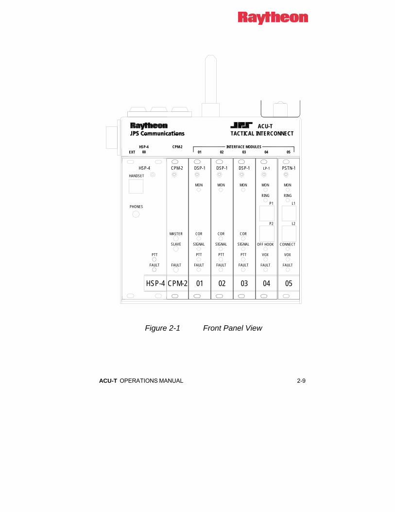
Figure 2-1 Front Panel View

2-10 ACU-T OPERATIONS MANUAL
0* #
2 3169
4 57 8
MIN
HSP
J0
EXT 01J1
SYSTEM CONNECTION STATUS
NET1
3
2
00HSP
VOLUME
05EXTENSION
01 02 03 04
EXT 05J5
EXT 02J2
EXT 03J3
EXT 04J4
CHARGERON
SPEAKERON
TACTICAL INTERCONNECT
POWER ON
ACU-T
10.850
11.370
Figure 2-2 Top Panel View

ACU-T OPERATIONS MANUAL 2-11
J7POWER15 VDC-
BATTERY INPUTS J8 & J9 ACCEPT 9-16 VDC @ 1-4 AMPS.THESE INPUTS ARE IN PARALLEL AND ARE NOT ISOLATED FROM EACH OTHER.
J7 IS 12-16 VDC INPUT @ 1-4 AMPS, AND IS ISOLATED FROM J8 & J9.
J7 CAN BE USED WITH 12 VOLT CIGARETTE LIGHTER PLUG TOCHARGE BATTERIES AT J8 AND/OR J9, BUT ONLY WITH VEHICLE ENGINE RUNNING.
F15A
TYPE 2AGMAIN
POWER
7 9
1 3
I0
OFFON
SIGNAL
J0GND
SPKR OUTGND
ANALOG GNDMIC IN
PTT OUTCOR IN
LINE OUTMIC LOW
CPCCONNECTOR
PIN #123456789
JI-J5GND
AUX OUTTx B
ANALOG GNDRx A
PTT OUTCOR IN
Tx ARx B
BATTERYCHARGER
+
J10RS-232
BATTERY
J8
+-
J9
- +
7.300
6.520
6.700
7.025
9.000
NOTE: HANDLE FOLDS DOWN
Figure 2-3 Rear Panel View

2-12 ACU-T OPERATIONS MANUAL
2.6 Power Requirements The ACU-T will operate with DC supply voltage from +9 to +16 VDC. There are two isolated power inputs. Input J7 is designed to accept +15VDC from an AC adaptor (included with the unit) to power both the ACU-T and the battery charger. Inputs J8 and J9 (wired in parallel; not isolated from each other) accept nominal 12V battery power. With the included AC adapter connected to J7 and a 12V battery connected to either J8 or J9, the battery will be charged (if the battery charger switch is on) as long as the AC adapter is supplying power. If the AC line voltage fails or the adapter is unplugged from J7, the battery will automatically take over the power supply to the unit.
Two battery inputs (J8 and J9) are provided so that a fresh battery may be connected to the unit without causing the ACU-T to lose power during a battery change.
The only requirement for having a voltage of +15VDC at J7 is to operate the battery charger. If the charger is not needed, any voltage as low as +9VDC will power the unit from J7.
Actual power consumption depends on the number of interface modules installed. The DC power input characteristic of the unit is essentially constant power, i.e., the input power requirement is constant so the input current varies with the input voltage and number of modules installed. A fully loaded chassis consumes 1.8A (21.6W) when run at a nominal 12VDC.
CAUTION: Always disconnect input power cabling from the ACU-T prior to servicing the unit.
NOTE: Any DC power supply connected to the ACU-T DC input must be Safety Extra Low Voltage (SELV) certified.
ACU-T OPERATIONS MANUAL 2-13
2.6.1 Battery Power for the ACU-T A 12V gel-cell battery connected to J8 or J9 can power the ACU-T. An 18AH battery is recommended. When both battery and an AC adapter are connected, the battery will be charged and the unit will be powered from adapter power as long as the AC adapter remains powered or connected to the unit. If the adapter is unpowered or disconnected, the unit will automatically switch over to battery power. When powered by a +12V battery at J8 or J9, the ACU-T current consumption is approximately the following: 0.3A + (0.3A * # interface modules). In other words, the basic chassis with CPM and HSP modules draws 0.3 Amps, and each interface module draws an additional 0.3 Amp. So the current consumption would be the following:
Chassis with 1 module = 0.6A
Chassis with 2 modules = 0.9A
• Chassis with 5 modules = 1.8A (fully loaded ACU-T)
The recommended 18AH battery will give about 10 hours of operation with a fully-loaded ACU-T, and correspondingly longer operating time when fewer than five modules are installed.
2.6.2 Charge Switch The rear panel Battery Charger Switch must be set to ON to charge batteries connected to J8 or J9. The switch should be set to OFF if any source of power except a battery is connected to either J8 or J9.
2.6.3 Charger ON LED This LED on the top panel will be lit when the battery charger is turned ON and a battery is connected and charging. The LED is brightest when a battery is low on charge and dims as the battery nears full charge. If there is no battery connected, or the battery is fully charged, the indicator will not light even if the Charger switch is set to ON.

2-14 ACU-T OPERATIONS MANUAL
2.6.4 Reverse Polarity Protection Power input J7 is protected from reverse polarity by a series diode. If reverse polarity power is applied at J7, the unit will not operate and no damage will occur.
Inputs J8 and J9 are reverse polarity protected by diodes to ground at these inputs and series fuses in the cables. Note that cables attached to these inputs MUST have a series fuse. If reverse polarity power is applied at either J8 or J9, the internal diode will conduct and blow the series cable fuse. The unit will not operate and no damage will occur except for a blown fuse.
2.6.5 Fuse Information This section identifies the fuses used in and with the ACU-T.
F1 fuses the total DC power to the unit. It protects the unit from fire or component damage in the even of an internal short circuit in the ACU-T or any of the installed modules.
The Universal battery cable and Aux Power cable both have built-in fuses. These fuses protect against applied reverse polarity power as well as internal faults in the unit.
Table 2-1 ACU-T Fuses F1 5A, 250V,
3AG Main Fuses all power to the
ACU-T.
--- 10A, 250V, AGC
Battery Cable
Reverse polarity protection for J8, J9.
--- 10A, 250V, AGC
Aux Power Cable
Reverse polarity protection for J8, J9.

ACU-T OPERATIONS MANUAL 2-15
2.7 Installation Checklist
Table 2-2 Installation Checklist Provide suitable Mounting and Cooling.
See Section 2.5.
Battery Power needed? See Section 2.6.1 and 2.6.2. Make Interconnections. See Section 2.8 for External
Interconnect Information. Serial Remote Control needed? Set Serial Remote control
ON with CPM SW1-3. Set Baud Rate with CPM SW1-1 and 2.
Set Audio Input Levels if necessary. See Programming Items for the DSP-1 in Table 2-19.
Set Audio Output Levels if necessary. See Programming Items for the DSP-1 in Table 2-19.
Set COR Type and Polarity. See Programming Items for the DSP-1 in Table 2-19.
Set Squelch Type if necessary See Programming Items for the DSP-1 in Table 2-19
Set Telephone Line Level if necessary. See Programming Items for the PSTN-1 in Table 2-19.
Is COR Sampling needed? See Programming Items for the DSP-1 in Table 2-19.
Is Noise Reduction Needed? See Programming Items for the DSP-1 in Table 2-19.
Numerous other configuration options available but not included in this checklist. See the manual sections beginning with 2.9.

2-16 ACU-T OPERATIONS MANUAL
2.8 External Interconnect Information This section details the type and pin-out information for the ACU-T external connectors. The left-most slot in the chassis is reserved for the HSP-4 Handset/Speaker/Prompt Module and the second slot is for the CPM-2 Control Processor Module. Both of these modules are required for system operation. The 5 remaining slots may be occupied by any complement of the various ACU-T interface modules.
Each of the interface module slots (and the HSP-4 slot) has an associated CPC connector on the side panel. The pin connections presented at the side panel CPC connectors depend on the type of interface module installed in the associated slot. The connectors for the 5 interface module slots are labeled J1-J5 on the side panel. J1 is associated with the module plugged into the slot adjacent to the CPM-2 Module, and the J5 is the connector for the module plugged into the right-most slot. J0 provides external connections to the HSP-4 module.
To reference the modules and system users, the 5 slots that the interface modules plug into are associated with “extensions”. Extensions 01 through 05 correspond with side panel circular connectors J1 through J5. The HSP module is identified by the extension “J0” (think of this as similar to “O” for “Operator”).
System users employ these extension numbers to identify the connections they want to create. If a VHF radio were connected to the DSP module at J2 (extension 02) and the VHF operator wanted to make a call via the phone line connected to PSTN module in slot 5, he would use his DTMF keypad to call extension 05. If the VHF user wanted instead to communicate directly to the local operator at the ACU-T, he would use his DTMF keypad to connect to extension 00. A radio (or other 4-wire device) may also be connected to J0 using the same interface cable as would be used to connect it to J1 throuh J5. If this is done, a connection to extension 00 will interconnect this radio. See Section 3.4.3 for more information regarding the use of J0 to connect radios.
See Section 3 for full operational instructions.
ACU-T OPERATIONS MANUAL 2-17
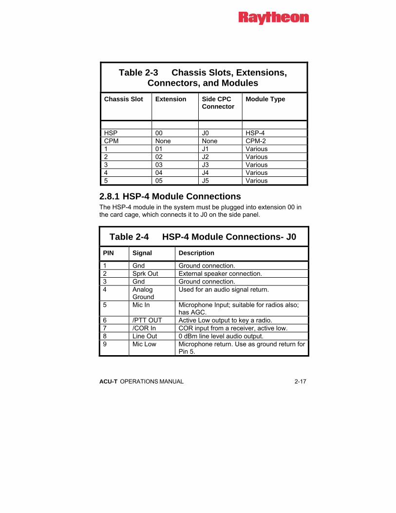
Table 2-3 Chassis Slots, Extensions, Connectors, and Modules
Chassis Slot Extension
Side CPC Connector
Module Type
HSP 00 J0 HSP-4 CPM None None CPM-2 1 01 J1 Various 2 02 J2 Various 3 03 J3 Various 4 04 J4 Various 5 05 J5 Various
2.8.1 HSP-4 Module Connections The HSP-4 module in the system must be plugged into extension 00 in the card cage, which connects it to J0 on the side panel.
Table 2-4 HSP-4 Module Connections- J0 PIN Signal Description
1 Gnd Ground connection. 2 Sprk Out External speaker connection. 3 Gnd Ground connection. 4 Analog
Ground Used for an audio signal return.
5 Mic In Microphone Input; suitable for radios also; has AGC.
6 /PTT OUT Active Low output to key a radio. 7 /COR In COR input from a receiver, active low. 8 Line Out 0 dBm line level audio output. 9 Mic Low Microphone return. Use as ground return for
Pin 5.
2-18 ACU-T OPERATIONS MANUAL
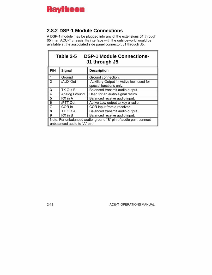
2.8.2 DSP-1 Module Connections A DSP-1 module may be plugged into any of the extensions 01 through 05 in an ACU-T chassis. Its interface with the outsideworld would be available at the associated side panel connector, J1 through J5.
Table 2-5 DSP-1 Module Connections- J1 through J5
PIN Signal Description
1 Ground Ground connection. 2 /AUX Out 1 Auxiliary Output 1- Active low; used for
special functions only. 3 TX Out B Balanced transmit audio output. 4 Analog Ground Used for an audio signal return. 5 RX in A Balanced receive audio input. 6 /PTT Out Active Low output to key a radio. 7 COR In COR input from a receiver. 8 TX Out A Balanced transmit audio output. 9 RX in B Balanced receive audio input. Note: For unbalanced audio, ground “B” pin of audio pair; connect unbalanced audio to “A” pin.

ACU-T OPERATIONS MANUAL 2-19
2.8.3 PSTN-1 Module Connections A PSTN-1 module may be plugged into extensions 01 through 05 in an ACU-T chassis.
Table 2-6 PSTN-1 Module Connections- J1 through J5
PIN Signal Description
1 Ground Ground connection. 2 /AUX In 2 Auxiliary Input 2- Active low; used for special
functions only. 3 Tel Line 1 Tip Telephone Line 1 Tip Connection; use JP2 to
enable. 4 Analog Ground Used for an audio signal return. 5 Tel Line 2 Ring Telephone Line 2 Ring Connection; use JP3
to enable. 6 /AUX Out 1 Auxiliary Output 1- Active low; used for
special functions only. 7 4WOUT 4-Wire Audio Output. 8 Tel Line 1 Ring Telephone Line 1 Ring Connection; use JP1
to enable. 9 Tel Line 2 Tip Telephone Line 2 Tip Connection; use JP4 to
enable.

2-20 ACU-T OPERATIONS MANUAL
2.8.4 LP-1 Module Connections An LP-1 module may be plugged into any of the extensions 01 through 05 in an ACU-T chassis.
Table 2-7 LP-1 Module Connections- J1 through J5
PIN Signal Description
1 Ground Ground connection. 2 /AUX In 2 Auxiliary Input 2- Active low; used for
special functions only. 3 Tel Line 1 Tip Telephone Line 1 Tip Connection. 4 Analog Ground Used for an audio signal return. 5 Tel Line 2 Ring Telephone Line 2 Ring Connection. 6 /AUX Out 1 Auxiliary Output 1- Active low; used for
special functions only. 7 /PTT In Active- Low PTT Input. 8 Tel Line 1 Ring Telephone Line 1 Ring Connection. 9 Tel Line 2 Tip Telephone Line 2 Tip Connection.
ACU-T OPERATIONS MANUAL 2-21
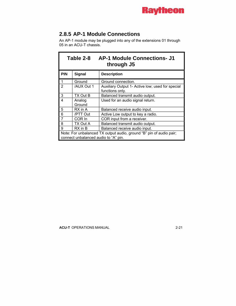
2.8.5 AP-1 Module Connections An AP-1 module may be plugged into any of the extensions 01 through 05 in an ACU-T chassis.
Table 2-8 AP-1 Module Connections- J1 through J5
PIN Signal Description
1 Ground Ground connection. 2 /AUX Out 1 Auxiliary Output 1- Active low; used for special
functions only. 3 TX Out B Balanced transmit audio output. 4 Analog
Ground Used for an audio signal return.
5 RX in A Balanced receive audio input. 6 /PTT Out Active Low output to key a radio. 7 COR In COR input from a receiver. 8 TX Out A Balanced transmit audio output. 9 RX in B Balanced receive audio input. Note: For unbalanced TX output audio, ground “B” pin of audio pair; connect unbalanced audio to “A” pin.

2-22 ACU-T OPERATIONS MANUAL
2.8.5.1 AP-1 Cable Information The AP-1 module applies DSP functions to its throughput audio and/or control lines. This audio can be applied to either the input or the output of other ACU-T interface modules. The AP-1 Option cabling determines whether its functions are applied to the associated ACU-T module’s input or to its output. The cable provided with the AP-1 module is designed to be used in series with the standard radio interface cable.
For example, if extra audio delay must be added to a trunked radio interfaced with a DSP-1 module in the ACU-T chassis, the AP-1 TX Option must be used.
To install, disconnect the trunked radio’s interface connector from the side panel of the ACU-T. Install the AP-1 module (configured for the proper audio delay) into a chassis slot adjacent to the DSP-1 module. Attach the AP-1 TX Option cable as follows:
• P1 connects to the DSP-1’s side panel connector
• P3 connects to the AP-1’s side panel connector
• P2 connects to the interface cable from the trunked radio; P2 is the same configuration as the ACU-T’s side panel connector so that it mates with any standard ACU-T interface cable.
2.8.6 Serial Remote Connector This female 9-pin DB-9 connector provides a serial RS-232 interface with the CPM-2 module. The connector is labeled J10 on the rear panel. Standard DCE pinout is used.
Table 2-9 Serial Remote Connections- J10 PIN Signal
2 TX Data 3 RX Data 5 Ground

ACU-T OPERATIONS MANUAL 2-23
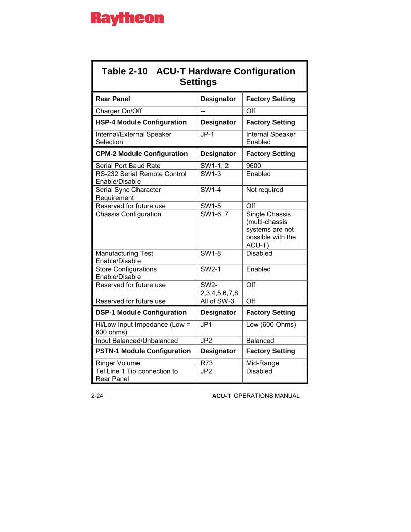
2.9 Hardware Configuration Settings In the ACU-T, there are two types of system and module configuration settings: Hardware and Programming. Changing physical pots, jumpers, and switches on each module adjusts hardware settings. Programming items for each module are set via the HSP-4 Keypad or by RS-232 remote control. In general, the hardware settings are done once at installation and need not be changed, while the programming items are more likely to be changed after installation to optimize system performance. This section explains all hardware configuration switch and jumper settings for each of the modules in a system. A full explanation of Programming Configuration Settings follows.
To access the potentiometers, jumpers and switches listed in Table 2-10, use the Extender Card found in the Accessory Kit. Remove the module needing adjustment and install the extender card in its place. Insert the Extender Card with its connector on the right side of the card (the Extender Card connector must be on the same side of the extender card as the module components). All modules can be safely "hot-plugged" (removed and re-inserted with the unit's power on) without damage, but interruptions to unit operation may occur.
2-24 ACU-T OPERATIONS MANUAL
Table 2-10 ACU-T Hardware Configuration Settings
Rear Panel Designator Factory Setting
Charger On/Off -- Off
HSP-4 Module Configuration Designator Factory Setting
Internal/External Speaker Selection
JP-1 Internal Speaker Enabled
CPM-2 Module Configuration Designator Factory Setting
Serial Port Baud Rate SW1-1, 2 9600 RS-232 Serial Remote Control Enable/Disable
SW1-3 Enabled
Serial Sync Character Requirement
SW1-4 Not required
Reserved for future use SW1-5 Off Chassis Configuration
SW1-6, 7 Single Chassis (multi-chassis systems are not possible with the ACU-T)
Manufacturing Test Enable/Disable
SW1-8 Disabled
Store Configurations Enable/Disable
SW2-1 Enabled
Reserved for future use SW2-2,3,4,5,6,7,8
Off
Reserved for future use All of SW-3 Off
DSP-1 Module Configuration Designator Factory Setting
Hi/Low Input Impedance (Low = 600 ohms)
JP1 Low (600 Ohms)
Input Balanced/Unbalanced JP2 Balanced PSTN-1 Module Configuration Designator Factory Setting
Ringer Volume R73 Mid-Range Tel Line 1 Tip connection to Rear Panel
JP2 Disabled
ACU-T OPERATIONS MANUAL 2-25
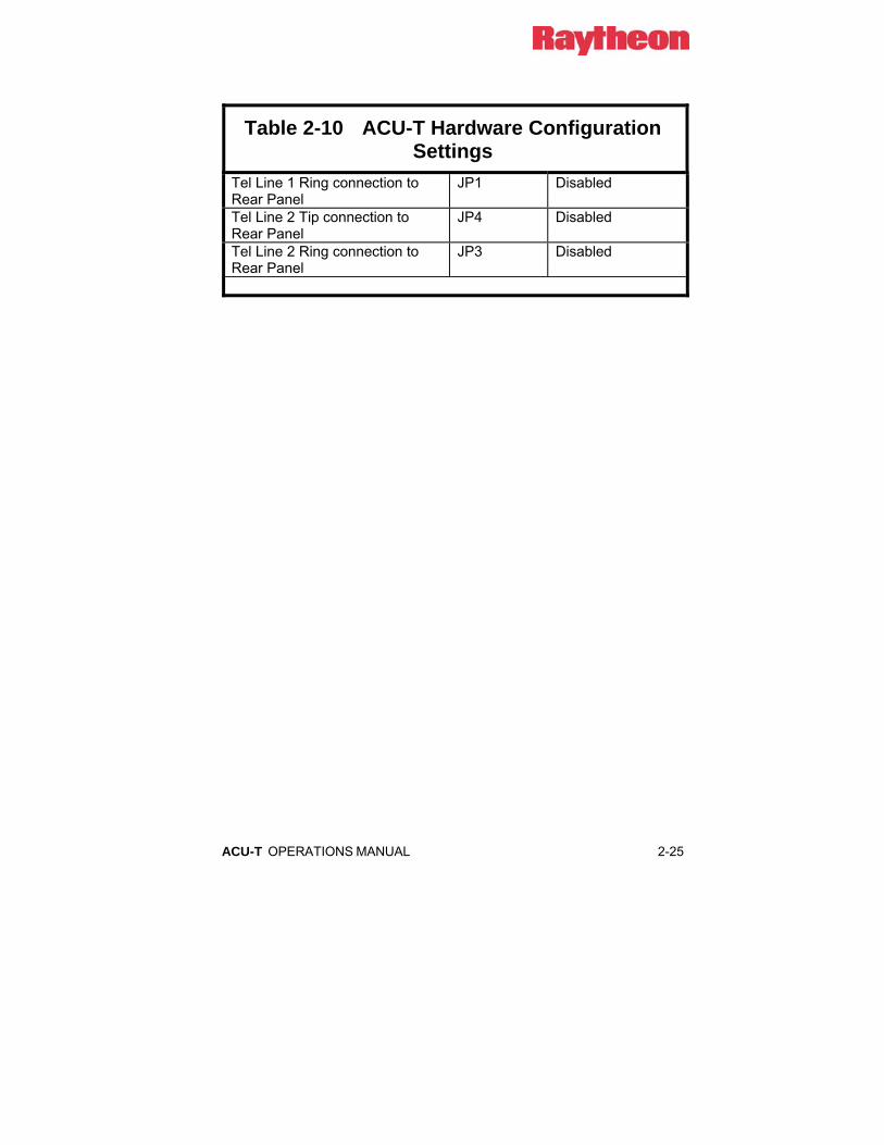
Table 2-10 ACU-T Hardware Configuration Settings
Tel Line 1 Ring connection to Rear Panel
JP1 Disabled
Tel Line 2 Tip connection to Rear Panel
JP4 Disabled
Tel Line 2 Ring connection to Rear Panel
JP3 Disabled

2-26 ACU-T OPERATIONS MANUAL
2.9.1 CPM-2 Switch Settings The dipswitches on the CPM-2 module configure the chassis for proper operation in its customer-specific application. There are two eight-position dipswitches on this module. The features associated with each individual dipswitch are described in the following paragraphs. Switches that do not currently have a feature assigned are reserved for future use and should be kept OFF. The CPM-2 dipswitches are only read by the ACU-T at unit power-up, so to change unit configuration, shut main power off, pull out the CPM-2 module, change dipswitch settings as required, reinstall the module and turn main power back on. If using the CPM-2 on an extender card, it will still be necessary to turn power off/on in order to get the unit to read the switches and change configuration accordingly. In the tables below, the default settings are marked with an asterisk.
2.9.1.1 Baud Rate SW1-1 and SW1-2
These switches set the external serial port baud rate. The serial port uses 8 data bits, 1 stop bit, and no parity.
Table 2-11 Baud Rate SW1-1 SW1-2 Baud Rate
Off Off 300 Baud On Off 1200 Off On 2400 On On 9600 *

ACU-T OPERATIONS MANUAL 2-27
2.9.1.2 Remote Control Enable SW1-3
This switch enables remote control via RS-232 and the external serial port. The default is Enabled; setting to Disabled does not change operation in any way except incoming RS-232 commands will be ignored.
Table 2-12 Remote Control Enable SW1-3 Remote Control
On Enabled * Off Disabled
2.9.1.3 Serial Sync Character SW1-4 This switch adds the requirement that all remote control commands are preceded by the synchronizing character ^ (ascii character 0x5E). The default setting is OFF, as this is not normally required. The sync character may improve remote control operation under electrically “noisy” conditions, such as the presence of high levels of RF energy.
Table 2-13 Serial Sync Character SW1-4 Sync Character
On Required Off Not Required *
NOTE: The ACU Controller program does not use the Serial Sync Character and will not function if this switch is turned on.

2-28 ACU-T OPERATIONS MANUAL
2.9.1.4 Reserved SW1-5, 6, 7
SW1-5 through SW1-7 are reserved for future use and should be kept in the OFF position.
2.9.1.5 Manufacturing Test SW1-8 The factory uses this switch for manufacturing test purposes only, and must be kept off.
Table 2-14 Manufacturing Test SW1-8 Manufacturing Test On Enabled Off Disabled *
2.9.1.6 Store Configuration SW2-1 SW2-1 enables the Store Configuration feature when in the ON position. This feature is controlled by the HSP-4 keypad, but will not function unless SW2-1 is on. See Section 3.4.2.7.
Table 2-15 Store Configuration SW2-1 Store Configuration Feature On Enabled * Off Disabled
2.9.1.7 SW2-2 Through SW2-8 SW2-2 through SW2-8 are reserved for future use and must be kept OFF to ensure proper operation.
2.9.1.8 SW3 All of the switches of SW3 are reserved for future use and must be kept OFF to ensure proper operation.

ACU-T OPERATIONS MANUAL 2-29
2.9.2 AP-1 Switch Settings
2.9.2.1 AP-1 General Information The AP-1 module is a general-purpose 4-wire module that can provide a variety of DSP operations. Unlike other ACU-T modules, the AP-1 does not communicate with the system audio and control bus structures on the ACU-T backplane. The AP-1 is basically “In Series” with the audio signal that is routed through it via the associated rear panel connector. The ACU-T chassis merely provides to the AP-1s DC power and a place to reside. The DSP functions of the AP-1 can operate either on the audio and control signal coming into the ACU-T module that it is associated with (AP-1 RX Option Assembly), or on the audio and control signal that’s exiting the associated ACU-T module (AP-1 TX Option Assembly). Alternatively, the AP-1’s DSP features can be used to modify signals not associated at all with the ACU-T. In this case, the customer can manufacture custom cabling to suit the application.
The functions enabled on the AP-1 module are determined by the settings of dipswitches SW3 and SW-4. See Table 2-16 and Error! Reference source not found.. Module configuration does not require the main power be cycled off and back on; module operation changes as soon as a switch setting changes.
2.9.2.2 Bypass Mode The front panel Bypass Switch and LED may be used to temporarily disable all DSP functions. When the switch is pressed in, the LED on, any configured function is disabled, and audio is routed straight through the module.
NOTE: When the AP-1 is set to the Bypass Mode, the audio is still converted to a digital data stream, passed through the DSP IC and reconstructed into an analog signal. The DSP performs no functions on the throughput audio.
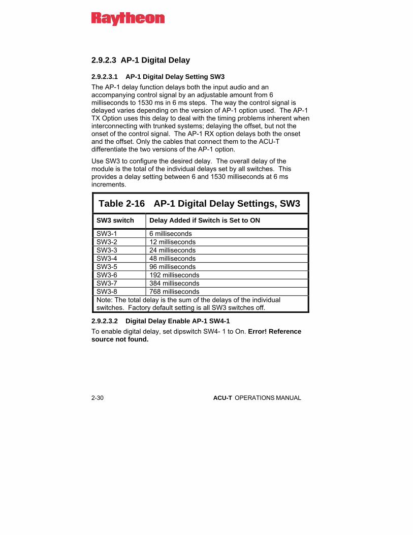
2-30 ACU-T OPERATIONS MANUAL
2.9.2.3 AP-1 Digital Delay
2.9.2.3.1 AP-1 Digital Delay Setting SW3 The AP-1 delay function delays both the input audio and an accompanying control signal by an adjustable amount from 6 milliseconds to 1530 ms in 6 ms steps. The way the control signal is delayed varies depending on the version of AP-1 option used. The AP-1 TX Option uses this delay to deal with the timing problems inherent when interconnecting with trunked systems; delaying the offset, but not the onset of the control signal. The AP-1 RX option delays both the onset and the offset. Only the cables that connect them to the ACU-T differentiate the two versions of the AP-1 option.
Use SW3 to configure the desired delay. The overall delay of the module is the total of the individual delays set by all switches. This provides a delay setting between 6 and 1530 milliseconds at 6 ms increments.
Table 2-16 AP-1 Digital Delay Settings, SW3 SW3 switch Delay Added if Switch is Set to ON
SW3-1 6 milliseconds SW3-2 12 milliseconds SW3-3 24 milliseconds SW3-4 48 milliseconds SW3-5 96 milliseconds SW3-6 192 milliseconds SW3-7 384 milliseconds SW3-8 768 milliseconds Note: The total delay is the sum of the delays of the individual switches. Factory default setting is all SW3 switches off.
2.9.2.3.2 Digital Delay Enable AP-1 SW4-1 To enable digital delay, set dipswitch SW4- 1 to On. Error! Reference source not found.
ACU-T OPERATIONS MANUAL 2-31
2.9.2.3.3 Control Signal Delay, AP-1 RX Option Both the onset and offset (turnoff) of the input control signal (COR) present at pin 7 of the module’s CPC side panel connector are delayed by the same amount as the audio; the delayed control signal output is provided at pin 6. An inherent DSP processing delay of 2 ms is present in addition to the set digital delay.
2.9.2.3.3.1 Control Signal Delay, AP-1 TX Option The onset of the PTT output is not delayed (relative to the corresponding COR input), however the offset of the output is delayed by the AP-1’s set delay duration. This effectively extends the duration of the PTT output. When a non-trunked user is interconnected with a trunked system, he will hit his PTT switch and begin talking immediately.
An inherent DSP processing delay of 2 ms is present in addition to the set digital delay.
2.9.2.4 AP-1 Function Enable Switches, SW4 The table below lists the switches that must be turned on to enable the various DSP functions. The AP-1 module can’t simultaneously perform all of the functions listed (nor does it make sense to).
• The AP-1 can always provide digital delay
• The AP-1 can also be set to be either a tone detector or a tone generator (but not both at the same time)
• The AP-1 can perform the tone detect or tone generate function at either of two frequencies (but not both)
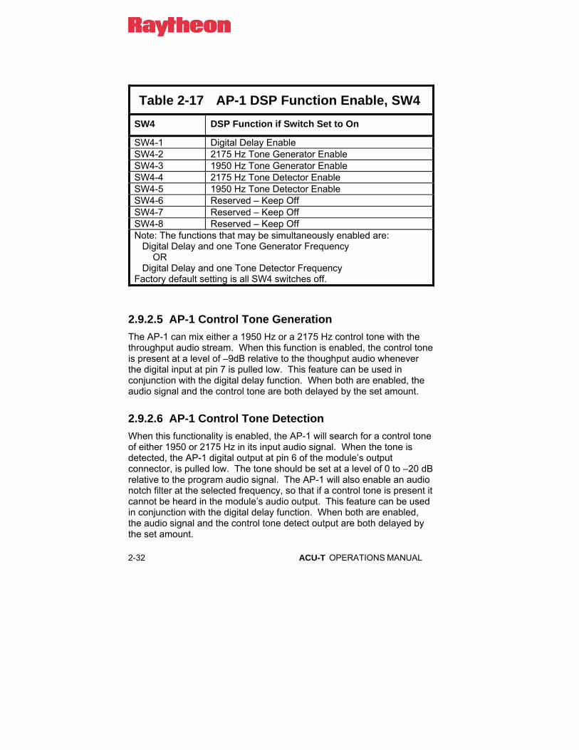
2-32 ACU-T OPERATIONS MANUAL
Table 2-17 AP-1 DSP Function Enable, SW4 SW4 DSP Function if Switch Set to On
SW4-1 Digital Delay Enable SW4-2 2175 Hz Tone Generator Enable SW4-3 1950 Hz Tone Generator Enable SW4-4 2175 Hz Tone Detector Enable SW4-5 1950 Hz Tone Detector Enable SW4-6 Reserved – Keep Off SW4-7 Reserved – Keep Off SW4-8 Reserved – Keep Off Note: The functions that may be simultaneously enabled are: Digital Delay and one Tone Generator Frequency OR Digital Delay and one Tone Detector Frequency Factory default setting is all SW4 switches off.
2.9.2.5 AP-1 Control Tone Generation The AP-1 can mix either a 1950 Hz or a 2175 Hz control tone with the throughput audio stream. When this function is enabled, the control tone is present at a level of –9dB relative to the thoughput audio whenever the digital input at pin 7 is pulled low. This feature can be used in conjunction with the digital delay function. When both are enabled, the audio signal and the control tone are both delayed by the set amount.
2.9.2.6 AP-1 Control Tone Detection When this functionality is enabled, the AP-1 will search for a control tone of either 1950 or 2175 Hz in its input audio signal. When the tone is detected, the AP-1 digital output at pin 6 of the module’s output connector, is pulled low. The tone should be set at a level of 0 to –20 dB relative to the program audio signal. The AP-1 will also enable an audio notch filter at the selected frequency, so that if a control tone is present it cannot be heard in the module’s audio output. This feature can be used in conjunction with the digital delay function. When both are enabled, the audio signal and the control tone detect output are both delayed by the set amount.
ACU-T OPERATIONS MANUAL 2-33
2.9.2.7 AP-1 Installation Notes When installing the TX AP-1 Option or the RX AP-1 Option to an existing ACU-T system, plug the AP-1 module into the ACU-T chassis, preferably to the right of the module that it will work with, and connect the associated cable. The connectors at the short “Y” end of the cable are assembled to the ACU-T chassis, and the cable previously connected to the ACU-T is now connected to the remaining connector, which has the same configuration as an ACU-T side panel connector.
The AP-1 is factory set for unity gain and needs not be adjusted for applications requiring 0dBm in, 0 dBm out (as would be needed if the AP-1 is semi-transparent to the throughput audio). For other input/output levels:
If the ACU-T AP-1 RX Option is used, adjust the output from the radio or other 4-wire device into the AP-1 with the AP-1 input potentiometer. Adjust the output to the radio via the DSP-1 transmit level programming items. If the AP-1 TX Option is used, adjust the audio output from the radio or other 4-wire device into the DSP-1 module via the DSP-1 transmit level programming items. Adjust the output from the AP-1 to the external device with the AP-1 output potentiometer.

2-34 ACU-T OPERATIONS MANUAL
2.9.3 LP-1 Jumper Settings
Table 2-18 Jumper Settings LP-1 Input/Output Definition Setting Level Jumper
High +3 dBm JP4 Norm 0 dBm JP4
Line Input
4 Wire Input
Low -3 dBm JP4 High -6 JP3 Norm -9 JP3
Microphone In
2 Wire Input
Low -12 JP3 High +3 dBm JP2 Norm 0 dBm JP2
Line Out
4 Wire Output
Low -3 dBm JP2 High -3 dBm JP1 Norm -6 dBm JP1
Handset Speaker
2 Wire Output
Low -9 dBm JP1 Phone Enable Enabled JP7 4 Wire Enable Disabled
JP8
Pins 2-3 50 mA Loop Current Pins 1-2 20 mA
JP5
Pins 2-3 -12V
N/A
Loop Voltage Pins 1-2 -48V (see
note)
JP6
NOTE: -48V Loop Voltage is a special option. Consult us.
ACU-T OPERATIONS MANUAL 2-35
2.10 Programming Configuration Settings
The ACU-T modules are individually programmed via the Top panel keypad, or by the ACU Controller software included with the unit. This section and Section 2.11 explain the programming commands as they are entered via the keypad.
Refer to Table 2-19, which provides all Configuration Programming Items.
2.10.1 To Program a Module: 1. Enter the programming mode by pressing * 9 9 on the keypad. The
ACU-T responds with the voice prompt "Setup Mode". Each time a user successfully enters one of the programming commands the ACU responds with “Ready”. The ACU-T stays in programming mode until the user exits this mode by entering the * # (star pound) sequence. The user does not have to enter * # until all programming is complete. The configuration changes are not entered into non-volatile memory (permanent storage) until the * # sequence is entered. All programming configuration changes are then automatically stored in non-volatile memory. These settings are retained (including following the cycling of ACU-T main power) unless the programming mode is re-entered and new settings stored, or a “Reset to Factory Settings” command is entered.
NOTE: If the ACU-T is currently operating under serial remote control via the ACU Controller, any programming via the keypad is disabled and the “Invalid Entry” voice prompt will be heard. To override console control, enter * 3 7 and wait for the “Ready” prompt. Programming via the keypad can then begin. Any configuration changes made will not be seen via the console program until it executes the “Retrieve Current Configuration” command from the “File” pulldown menu, or until it is is terminated and restarted.

2-36 ACU-T OPERATIONS MANUAL
2. When in the programming mode, select the individual module you wish to program by entering * 0 1 n n, where “n n” is the two-digit extension number of the module to be programmed. The extension numbers will be from 01 through 05. For example, to set a parameter on a DSP-1 module that is installed in extension slot 05, the user first enters the “Select Module to Program” command * 0 1 0 5. Once this command is given user may then enter as many programming items as desired for the selected module. If the user mistakenly selects an extension slot that is empty or non-existent, or there is another reason why the selected module is not valid for programming, the ACU-T will respond with an error message. There are no programming items for the HSP-4 module.
NOTE: The System Programming Items at the start of Table 2-19 are system-wide programming commands that do not require the selection of a module. To execute these items, enter the programming mode, but do not select a particular module.
3. Now that a module is selected, begin actual programming. Enter the desired programming command, following the format described in Table 2-19. Continuing the example from step #2 above: To set the receive level to 0 dBm on a DSP-1 module located in extension slot 05, the user first selects this module by entering * 0 1 0 5, the ACU responds with “05 Ready”, and the user then sets the receive level to 0 dBm by entering * 0 2 3. The ACU responds with “Ready”.

ACU-T OPERATIONS MANUAL 2-37
4. When all parameters for a selected module are complete, another module can be chosen for programming as in step #2 above, or the user can exit the programming mode at this time, which will store all settings. This is accomplished by entering * #. The ACU-T responds with “Saving configuration” followed by “Configuration has been saved”.
NOTE: If the programming mode is not exited by pressing * # before the power to the ACU-T is turned off, none of the new configuration settings made will be saved.
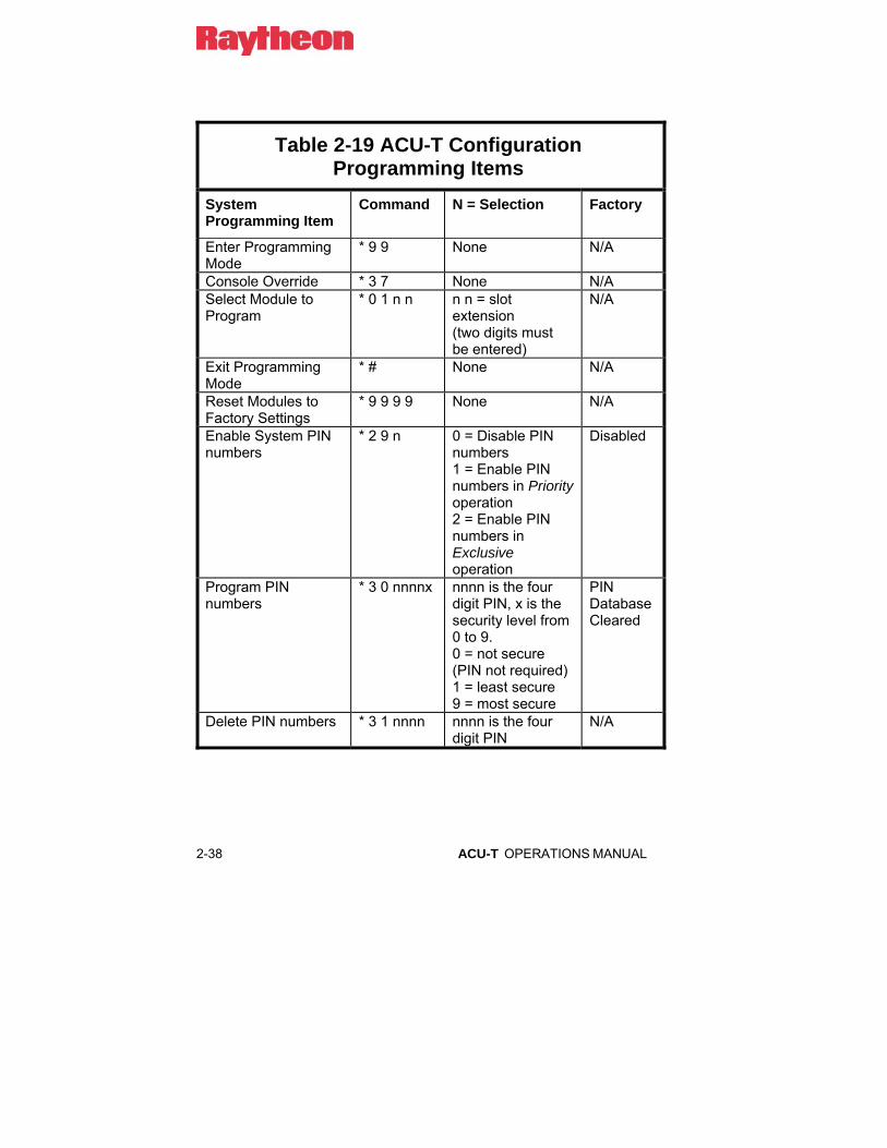
2-38 ACU-T OPERATIONS MANUAL
Table 2-19 ACU-T Configuration Programming Items
System Programming Item
Command N = Selection Factory
Enter Programming Mode
* 9 9 None N/A
Console Override * 3 7 None N/A Select Module to Program
* 0 1 n n n n = slot extension (two digits must be entered)
N/A
Exit Programming Mode
* # None N/A
Reset Modules to Factory Settings
* 9 9 9 9 None N/A
Enable System PIN numbers
* 2 9 n 0 = Disable PIN numbers 1 = Enable PIN numbers in Priority operation 2 = Enable PIN numbers in Exclusive operation
Disabled
Program PIN numbers
* 3 0 nnnnx nnnn is the four digit PIN, x is the security level from 0 to 9. 0 = not secure (PIN not required) 1 = least secure 9 = most secure
PIN Database Cleared
Delete PIN numbers * 3 1 nnnn nnnn is the four digit PIN
N/A

ACU-T OPERATIONS MANUAL 2-39
HSP-4 Programming Item
Command N = Selection Factory
Squelch Type * 5 3 n 0 = Mic 1 = VOX
Mic
DSP-1 Programming Item
Command N = Selection Factory
Receive Level * 0 2 n 0 = 12dBm 1 = 8dBm 2 = 4dBm 3 = 0dBm 4 = -4dBm 5 = -8dBm 6 = -12dBm 7 = -16dBm 8 = -20dBm 9 = -26dBm
0dBm
Transmit Level * 0 3 n 0 = -26dBm 1 = -20dBm 2 = -16dBm 3 = -12dBm 4 = -8dBm 5 = -4dBm 6 = 0dBm 7 = 4dBm 8 = 8dBm 9 = 12dBm
0dBm
COR Polarity * 0 4 n 0 = Active Low 1 = Active High
Active Low
Full/Half Duplex * 0 8 n 0 = Full, 1 = Half Half DTMF Mute Timer Value
* 0 9 n 0 = Off 1 = 0.5 sec 2 = 1 sec 3 = 1.5 sec 4 = 2 sec 5 = 2.5 sec 6 = 3 sec 7 = 3.5 sec 8 = 4 sec 9 = 4.5 sec
Off

2-40 ACU-T OPERATIONS MANUAL
Audio Delay H/W COR Mode
* 1 0 n 0 = 20 ms 1 = 60 ms 2 = 100 ms 3 = 140 ms 4 = 180 ms 5 = 220 ms 6 = 260 ms 7 = 300 ms
20 ms
Audio Delay VOX Mode
* 1 0 n 0 = 20 ms 1 = 60 ms 2 = 100 ms 3 = 140 ms 4 = 180 ms 5 = 220 ms 6 = 260 ms 7 = 300 ms
60 ms
Audio Delay VMR Mode
* 1 0 n Less than 220 msec not allowed. 0,1,2,3,4,5 = 220 ms 6 = 260 ms 7 = 300 ms
220 ms
VMR/VOX Threshold
* 1 1 n 0 = Low (Highest Sensitivity) 1 = Med1 2 = Med2 3 = High (Lowest Sensitivity) 4-9 = Reserved for special applications – do not use
Med1
VOX Hangtime * 1 2 n 0 = 175 ms 1 = 375 ms 2 = 575 ms 3 = 775 ms 4 = 975 ms 5 = 1.175 sec 6 = 1.375 sec 7 = 1.575 sec
775 ms

ACU-T OPERATIONS MANUAL 2-41
VMR Hangtime * 1 2 n Less than 775 not
allowed. 1, 2, 3 = 775 ms 4 = 975 ms 5 = 1.175 sec 6 = 1.375 sec 7 = 1.575 sec
775 ms
COR (squelch) Type
* 1 4 n 0 = COR 1 = VMR 2 = Reserved 3 = VOX
VOX
COR Sampling On/Off
* 1 8 n 0 = Disabled 1 = Enabled
Disabled
COR Sampling Initial Delay Time
* 1 9 n 0 = 2 sec 1 = 4 sec 2 = 6 sec 3 = 8 sec 4 = 10 sec 5 = 12 sec 6 = 14 sec 7 = 16 sec 8 = 18 sec 9 = 20 sec
10 sec
COR Sampling Interval
* 2 0 n 0 = 1 sec 1 = 2 sec 2 = 3 sec 3 = 4 sec 4 = 5 sec 5 = 6 sec 6 = 7 sec 7 = 8 sec 8 = 9 sec 9 = 10 sec
5 sec

2-42 ACU-T OPERATIONS MANUAL
COR Sampling Window Width
* 2 1 n 0 = 50 ms 1 = 100 ms 2 = 150 ms 3 = 200 ms 4 = 250 ms 5 = 300 ms 6 = 350 ms 7 = 400 ms 8 = 450 ms 9 = 500 ms
150 ms
Noise Reduction Value (Peaker Value)
* 2 2 n 0 = Off 1 = Minimum 9 = Maximum
Off
Audio Muted when Squelched
* 2 3 n 0 = Muted 1 = Not Muted
Muted
Transmit Keying Tones
* 2 5 n 0 = None 1 = 1950 Hz Continuous 2 = EIA Sequence (F1 function tone, 1950 Hz)
None
COR Inhibit Time after PTT
* 2 6 n 0 = None 1 = 100 ms 2 = 200 ms 3 = 400 ms 4 = 800 ms 5 = 1 sec 6 = 2 sec 7 = 3 sec 8 = 4 sec 9 = 5 sec
100 ms
PTT or COR Priority (Half Duplex only)
* 2 7 n 0 = COR Priority 1 = PTT Priority
PTT Priority
Keying Tone Amplitude Does not apply to EIA Keying
* 2 8 n 0 = -6 dB, 1 = -9 dB, 2 = -12 dB, 3 = -15 dB
-9 dB

ACU-T OPERATIONS MANUAL 2-43
Module security level * 3 2 n 0 = Not Secure
1 = Least Secure 9 = Most Secure
Not Secure
DTMF Enable * 3 8 n 0 = Disabled 1 = Enabled
Enabled
High Frequency Equalizer
* 3 9 n 0 = Reserved 1 = 5 dB cut 2 = 3.5 dB cut 3 = 2 dB cut 4 = Flat 5 = 2 dB boost 6 = 3.5 dB boost 7 = 5 dB boost 8 and 9 = Reserved
Flat
DTMF Pre-emphasis (HSP-4 keypad only)
* 4 0 n 0 = DTMF Pre-emphasized 1 = DTMF Not Pre-emphasized
Pre-emphasis
Auxiliary Output Control
* 4 1 n 0 = Future option 1 = Local control by the module
Local Control

2-44 ACU-T OPERATIONS MANUAL
TX Audio Delay (was “Radio Type Selection”)
* 4 3 n 0 = No Delay 1 = 200 ms 2 = 400 ms 3 = 600 ms 4 = 800 ms 5 through 9 reserved for future use
No Delay
Voice Prompt Initiation Delay
* 4 4 n 0 = No Delay 1 = 50 ms 2 = 100 ms 3 = 500 ms 4 = 750 ms 5 = 1 sec 6 = 2 sec 7 = 3 sec 8 = 4 sec 9 = 5 sec
100 ms

ACU-T OPERATIONS MANUAL 2-45
PSTN-1 Programming Item
Command n = Selection Factory
Telephone Line Levels
* 0 2 n 0 = 0dBm 1 = -3dBm 2 = -6dBm 3 = -9dBm 4 = -12dBm 5 = -15dBm 6 = -18dBm 7 = -21dBm 8 = -24dBm
-9dBm
Telephone RX Level Boost
* 0 3 n 0 = 0 dB 1 = 2.5 dB 2 = 4.5 dB 3 = 6 dB 4 = 7.4 dB 5 = 8.5 dB 6 = 9.5 dB 7 = 10. 5 dB 8 = 11.3 dB 9 = 12 dB
6 dB
PSTN Type * 0 5 n 0 = Normal 1 = Satcom
Normal
PSTN Dialing Mode * 0 6 n 0 = DTMF 1 = Pulse
DTMF
DTMF Mute Timer * 0 9 n 0 = Off 1 = 0.5 sec 2 = 1 sec 3 = 1.5 sec 4 = 2 sec 5 = 2.5 sec 6 = 3 sec 7 = 3.5 sec 8 = 4 sec 9 = 4.5 sec
1 sec
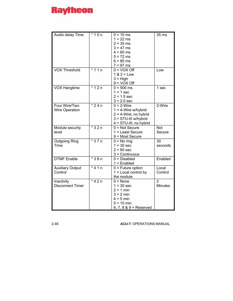
2-46 ACU-T OPERATIONS MANUAL
Audio delay Time * 1 0 n 0 = 10 ms
1 = 22 ms 2 = 35 ms 3 = 47 ms 4 = 60 ms 5 = 72 ms 6 = 85 ms 7 = 97 ms
35 ms
VOX Threshold * 1 1 n 0 = VOX Off 1 & 2 = Low 3 = High 9 = VOX Off
Low
VOX Hangtime * 1 2 n 0 = 500 ms 1 = 1 sec 2 = 1.5 sec 3 = 2.0 sec
1 sec
Four Wire/Two Wire Operation
* 2 4 n 0 = 2-Wire 1 = 4-Wire w/hybrid 2 = 4-Wire; no hybrid 3 = STU-III w/hybrid 4 = STU-III; no hybrid
2-Wire
Module security level
* 3 2 n 0 = Not Secure 1 = Least Secure 9 = Most Secure
Not Secure
Outgoing Ring Time
* 3 7 n 0 = No ring 1 = 30 sec 2 = 60 sec 3 = Continuous
30 seconds
DTMF Enable * 3 8 n 0 = Disabled 1 = Enabled
Enabled
Auxiliary Output Control
* 4 1 n 0 = Future option 1 = Local control by the module
Local Control
Inactivity Disconnect Timer
* 4 2 n 0 = None 1 = 30 sec 2 = 1 min 3 = 2 min 4 = 5 min 5 = 10 min 6, 7, 8 & 9 = Reserved
2 Minutes

ACU-T OPERATIONS MANUAL 2-47
Voice Prompt Initiation Delay
* 4 4 n 0 = No Delay 1 = 50 ms 2 = 100 ms 3 = 500 ms 4 = 750 ms 5 = 1 sec 6 = 2 sec 7 = 3 sec 8 = 4 sec 9 = 5 sec
No Delay
LP-1 Programming Item
Command n = Selection Factory
DTMF Mute Timer * 0 9 n 0 = Off 1 = 0.5 sec 2 = 1 sec 3 = 1.5 sec 4 = 2 sec 5 = 2.5 sec 6 = 3 sec 7 = 3.5 sec 8 = 4 sec 9 = 5 sec
1 second
Audio Delay Time * 1 0 n 0 = 10 ms 1 = 35 ms 2 = 60 ms 3 = 85 ms 4 = 110 ms 5 = 135 ms 6 = 160 ms 7 = 185 ms
60 ms
VOX Threshold * 1 1 n 0 = VOX Off 1 = Low 2 = Med 3 = High 9 = Off
Med
VOX Hangtime * 1 2 n 0 = 10 ms 1 = 750 ms 2 = 1.5 sec 3 = 2.25 sec
750 ms

2-48 ACU-T OPERATIONS MANUAL
Module security level
* 3 2 n 0 = Not Secure 1 = Least Secure 9 = Most Secure
Not Secure
Dial and Busy Tone Style
* 3 3 n 0 = USA Style 1 – 9 = Reserved
USA
Ring Cadence * 3 4 n 0 = USA Style 1 = European Style 2 – 9 = Reserved
USA
Dial Tone Enable * 3 5 n 0 = Dial Tone Disabled 1 = Dial Tone Enabled
Enabled
Ringback Enable * 3 6 n 0 = Ringback Disabled 1 = Ringback Enabled
Enabled
Outgoing Ring Time
* 3 7 n 0 = No ring 1 = 30 sec 2 = 60 sec 3 = Continuous
30 seconds
DTMF Enable * 3 8 n 0 = DTMF Disabled 1 = DTMF Enabled
Enabled
Auxiliary Output Control
* 4 1 n 0 = Future option 1 = Local control by the module
Local Control
Voice Prompt Initiation Delay
* 4 4 n 0 = No Delay 1 = 50 ms 2 = 100 ms 3 = 500 ms 4 = 750 ms 5 = 1 sec 6 = 2 sec 7 = 3 sec 8 = 4 sec 9 = 5 sec
No Delay

ACU-T OPERATIONS MANUAL 2-49
2.11 Programming Configuration Settings
2.11.1 System Programming and Operating Items
See Section 2.10 for a basic overview explaining how to enter the following programming items via the ACU-T keypad. All of the commands are listed in Table 2-19 and described in detail below. The modules can be programmed using an IBM PC-compatible computer running Windows 95, 98, or NT, and the ACU Controller Software. Complex systems with a variety of different radios will be much easier to set up and maintain with the controller software.
2.11.1.1 Enter Programming Mode Use the command * 9 9 to enter the programming mode. Once in this mode, the programming of each individual module’s configuration items is possible. Unless otherwise specified, the programming items listed in Table 2-19 or this section can only be entered when the ACU-T is in the Programming Mode.
2.11.1.2 Console Override If the ACU-T is currently under serial remote control using the ACU Controller software, programming via the keypad is disabled. To override the console software and re-enable programming via the keypad, enter * 3 7 at the keypad. Configuration changes made during console override will not be available at the console screen until the “Retrieve Current Configuration” option is selected from the “File” pulldown menu.
2-50 ACU-T OPERATIONS MANUAL
2.11.1.3 Select a Module to Program After entering the programming mode, use the command * 0 1 n n to select the slot number of the module you wish to program, where nn is the two-digit slot number. For example, to program the module in slot 5, enter * 0 1 0 5. After all programming commands are complete for one module, the programming of another module may begin, using this command to select that module. It is not necessary to exit and re-enter the programming mode each time a new module is programmed.
2.11.1.4 Exit Programming Mode When programming is complete, use the command * # to exit the programming mode and store the configuration in non-volatile memory.
2.11.1.5 Reset Modules to Factory Settings The command * 9 9 9 9 causes all modules in the ACU-T chassis to be reset to the factory settings. Be careful, as using this command will erase all custom configuration programming. This command can only be issued from programming mode.
2.11.1.6 PIN Numbers This command configures PIN operation for the ACU-T. PIN numbers (Personal Identification Numbers) are used to control access to the ACU-T network; see Section 3.6 for full details. Enable PIN numbers in the Priority Mode by entering * 2 9 1, or in the Exclusive Mode by entering * 2 9 2. To Disable PIN numbers enter * 2 9 0. When either PIN mode is enabled, users attempting to access the system will be prompted by the ACU-T to enter their PIN. When in the Priority PIN Mode, the user’s password security level must be equal to or higher than the security level of the module to gain access. Exclusive PIN Mode operation requires the user’s password security level to be identical to the security level of the extension the user is attempting to access. Extension security levels are set for all types of interface modules using the * 3 2 n programming item. Instructions are included with each module’s list of programming items.

ACU-T OPERATIONS MANUAL 2-51
2.11.1.7 Program PIN Numbers The security level of each PIN is entered into the ACU-T database by this command. Up to 20 different PIN numbers may be entered. To enter a PIN into the database and/or set the level for the PIN, enter * 3 0 n n n n x, where n n n n is the four digit PIN and x is the security level to be associated with this PIN. There are 9 available security levels, ranging from 1 = least secure to 9 = most secure. The security level “0” is essentially meaningless, as a security feature, since an extension set to security level 0 does not require a PIN to gain access. PIN programming is a global command, meaning it’s not necessary to select a module to program when entering PIN numbers or setting PIN security levels.
2.11.1.8 Delete PIN Numbers To delete a particular PIN, enter * 3 1 n n n n, where n n n n is the four digit PIN. This is a global command. Note that it is not necessary to input the security level when deleting a PIN.
2.11.1.9 Module Security Level Selection This command sets a module’s security level. Enter * 3 2 n, where n is the security level, with 0 = not secure (no PIN required), 1 = least secure, up to 9 = most secure. This is not a global command. Each module’s security level must be individually set. To set the security level for a particular module, first use the “Select Module to Program” command.
2.11.2 HSP-4 Programming Items
2.11.2.1 HSP-4 Squelch Type There is only one programming item for the HSP-4 module. The * 5 3 n command sets the Squelch Type for the module. Unlike all other operating commands, the HSP-4 Squelch Type can only be set by the ACU-T keypad; it cannot be sent by the ACU Controller.
There are two squelch types: 0 = mic only (the handset mic switch must be depressed for the handset audio input to be enabled and transferred to the rest of the ACU-T system), 1 = mic or VOX (either the PTT switch or the detection of handset audio will enable the input).
The HSP-4 should be kept in the mic only mode unless a radio or other four-wire device is connected to J0 on the ACU-T side panel.
2-52 ACU-T OPERATIONS MANUAL
2.11.3 DSP-1 Programming Items
2.11.3.1 Receive Level (DSP-1) The command * 0 2 n programs the audio receive level for a selected DSP-1. A correct receive level setting is required to ensure proper operation. Too high a level may cause flat-topping and distortion, while too low a level won’t provide adequate audio volume. The front panel SIGNAL LED is provided as a guide to setting the level; raise the receive volume until the SIGNAL LED flashes momentarily on voice peaks. If the LED never lights, the level is too low; if the LED is on almost continuously, the level is set too high. The following procedure is suggested:
Connect the normal audio source to the module, and place the module in the program mode.
• Enter the command * 0 2 0 to set the module at its least-sensitive setting. If the SIGNAL LED is flashing on voice peaks, this setting is correct. If the LED is now on continuously, the incoming audio level is higher than can be accommodated by the DSP-1 module, and must be attenuated before reaching the module. If the SIGNAL LED is not flashing at the * 0 2 0 setting, the module’s gain must be increased; proceed to the next step.
• Raise the module’ receive gain one step at a time until the SIGNAL LED is flashing on voice peaks. For example, program * 0 2 1, then * 0 2 2, etc., until the LED is flashing during voice peaks but is not lit continuously.
• Among the DSP-1 module’s algorithms is a Peak Limiter to prevent clipping of loud audio peaks. This limiter has a fast attack time and slow recovery rate.

ACU-T OPERATIONS MANUAL 2-53
2.11.3.2 Transmit Level (DSP-1) The command * 0 3 n allows a module’s transmit (or output) audio level to be programmed. The transmit level must be set correctly to insure proper operation of radios or other equipment connected to this output. Too high a level may cause flat-topping, distortion, or over-modulation of a connected radio, while too low a level won’t provide adequate audio volume or modulation level. If the actual audio level requirement of the radio or other connected equipment is known, select this level from the Transmit Level row of Table 2-19. These levels assume a 600 Ohm termination. If the required level is not known, the following procedure is suggested:
• An input audio source for the module is required (so this audio can be sent back out through the transmit audio port). Use the Connect command to create a connection between the module to be programmed with the second module (which is providing audio), and then place the first module into the programming mode.
• Determine the proper input level to the connected equipment (output level from the module). It may be necessary to monitor the module’s output audio level at the connected equipment’s input port with an audio voltmeter or other means.
• Enter the command * 0 3 0 to set the output to its lowest level.
• Raise the output level one step at a time until the proper level is reached. For example, enter * 0 3 1, then * 0 3 2, etc., until the proper level is reached.
2.11.3.3 COR Polarity (DSP-1) The command * 0 4 n allows the module’s hardwired COR input to work with either an active low or an active high COR input. If the radio’s COR output goes low when a signal is being received, set the input to active low (* 0 4 0); if the radio’s COR output goes high when a signal is being received, set the input to active high (* 0 4 1). This configuration parameter does not need to be programmed unless the hardwire COR input will be used.

2-54 ACU-T OPERATIONS MANUAL
2.11.3.4 Full/Half Duplex (DSP-1) The command * 0 8 n configures the module for either full duplex or half duplex operation. Set to full duplex if the connected radios or equipment can transmit and receive at the same time. Set to half duplex otherwise. Enter * 0 8 0 for full duplex; * 0 8 1 for half duplex.
2.11.3.5 DTMF Mute Timer (DSP-1) When a module is not in the Data Mode (See Section 3.4.2.9), all DTMF signals detected in the receive audio are interpreted as commands meant for the receiving module. When the DTMF Mute Timer is enabled, the DTMF signals are “Muted”; that is, they are not passed on to the ACU-T internal audio bus to be routed to another module, nor are they sent back out in any module’s TX audio. A module cannot instantaneously mute a DTMF signal; some time is required to detect its presence. Therefore, when a DTMF signal first becomes present in the receive audio, a short burst is passed through. The DTMF mute timer ensures that, if a long string of DTMF characters are present in the receive input, a short burst of only the first DTMF character is passed through. This is accomplished by muting the audio as soon as the first character is detected, and then keeping the audio muted until the first character is complete, and until enough of the next character has been received so it is detected. Each time a new DTMF character is detected, the timer is reset. When the timer expires (because no new DTMF character is detected in the receive input), the audio is no longer muted.
The factory default is DTMF Mute Timer Disabled, as the majority of ACU-T systems do not employ DTMF control. This setting allows the DTMF signals to be passed through the system like all other audio. It also prevents inevitable occasional “falsing” on voice signals that are similar to a DTMF character; this falsing would momentarily mute throughput audio.
If DTMF control is used, it may be desirable to mute the DTMF characters as they may be annoying to other system users, and a timer setting of 1 second works well in most cases. If the setting is too low (because some system users transmit DTMF characters slowly), a short burst of DTMF will be passed through at the start of each DTMF character. The timer should be set to a value that is longer than the maximum time elapsed between the end of one DTMF character and the start of the next.

ACU-T OPERATIONS MANUAL 2-55
There are some circumstances when it’s important that incoming DTMF not be interpreted by the ACU-T as control input, but instead must be passed to other equipment. The settings used are different depending on whether the module that’s passing on the DTMF is a PSTN-1 module (which regenerates DTMF) or any other type of module (which do not).
2.11.3.5.1 Transmitting DTMF via a PSTN Module If the system will be used, for example, to allow a radio user to control a telephone answering machine via DTMF, the following will occur:
A radio with a DTMF keypad will transmit to a radio wired to a DSP-1 module. This DSP-1 will be cross-connected to a PSTN-1 module that is hooked to a phone line. If the radio user creates the cross-connection using the DTMF keypad, the DSP-1 module must be in the Command Mode when he does so. He must then use the keypad to put the DSP-1 module into the Data Mode. When in the Command mode, DTMF coming into the DSP-1 module is interpreted as system command input. When in the Data Mode, the incoming DTMF is interpreted as control characters intended for other equipment and is not interpreted as control commands (other than the DTMF sequence that signals the module to return to the command mode). See Section 3.4.2.9 for more information about the Command and Data Modes.
While in the Data Mode, the DTMF from the radio is detected by the DSP-1 module and relayed via the CPM-2 module to the cross-connected PSTN-1 module as serial data. The PSTN-1 regenerates and transmits the DTMF characters into the phone line. This Data Mode regeneration cleans up the DTMF, so any noise or frequency-response related distortion of the DTMF characters (caused by radio transmission of the DTMF) is not passed on to the phone line.
When the system is used in this way, the DSP-1 module should have its DTMF Mute Timer turned on, so that only the regenerated DTMF will be sent via the phone line.
2.11.3.5.2 Transmitting DTMF via a Module other than the PSTN-1
If it is desired that DTMF characters (being sent out by a module other than a PSTN-1) be passed through the system, the DTMF mute timer must be turned off. This is required because only the PSTN-1 regenerates DTMF; the others will just pass it through like any other program audio. The DTMF mute timer must be set to Off on the module that receives the DTMF or it cannot be passed on to the cross-connected module or modules.

2-56 ACU-T OPERATIONS MANUAL
Please note that it is possible, but not advisable, to retransmit DTMF, bringing DTMF into the ACU-T on one radio via a DSP-1 module and then retransmitting the DTMF on a second radio via a cross-connected DSP-1 module. The normal FM noise that will accompany the DTMF, along with frequency response related distortion (caused by pre-emphasis & de-emphasis in the radio audio circuits) might have an adverse affect on DTMF signal quality and detection.
The programming command * 0 9 n sets the DTMF Mute Timer, with timer settings of 0 = Off, 1 = 0.5 sec, 2 = 1 sec, 3 = 1.5 sec, 4 = 2 sec, 5 = 2.5 sec, 6 = 3 sec, 7 = 3.5 sec, 8 = 4 sec, and 9 = 4.5 sec. Since the majority of systems do not use DTMF signaling, the factory default sets n at 0, with the DTMF Mute timer turned off.
2.11.3.6 COR Type, VOX/VMR Threshold, Hangtime, and Audio Delay (DSP-1)
The DSP-1 modules must have positive knowledge that an input audio signal is present so they know when to key an associated transmitter. A signal that provides this information is called COR (for Carrier Operated Relay, sometimes referred to as COS Carrier Operated Squelch). The DSP-1 module can use an external hardwire COR line, an internal VMR (Voice Modulation Recognition) algorithm, or a VOX Squelch. In a full duplex connection, it may be desirable to ignore COR activity altogether and never mute the incoming audio. The correct selections depend on the type of radio or other equipment that is connected to the DSP-1 receive audio input.
• FM Radios - For best reliability, use a hardwire COR signal, if one is available from the radio’s own squelch circuit. If no hardwire COR signal is available, and the radio has a squelch circuit, use the radio’s squelch in conjunction with VOX mode. VMR should be used for FM radios that must be operated with an open squelch (receiver noise is present when there is no signal). The VOX cannot be used in this condition because it will open on receiver noise, but the VMR opens only on speech, not on receiver noise. When used in this mode, the VMR threshold must be set to Med2 or High to avoid falsing on white noise from the FM discriminator.
• AM Aircraft Radios - Again, the best choice is a hardwire COR line from the radio, if one is available. If this isn’t an option, VMR should be used. VMR thresholds of Low or Med1 may be most appropriate for this application.
ACU-T OPERATIONS MANUAL 2-57
• HF SSB Radios - The only reliable choice for HF radios is VMR. VMR thresholds of Low or Med1 may be most appropriate for this application.
• Non-Radio Applications - The choice for these applications is hardwire COR, if this signal is available. If not, use VOX if the audio is relatively noise-free; use VMR for noisy signals.
The command * 1 4 n sets the COR type to be used in the DSP-1: * 1 4 0 selects hardwire COR, * 1 4 1 selects VMR, * 1 4 2 is reserved for future applications, and * 1 4 3 selects VOX squelch. Whenever VMR or VOX are selected, the DSP-1 will switch to default audio delay and hangtime settings that work well for each of these COR types. These default settings are recommended, but not mandatory except as explained below. When VMR or VOX is selected, the defaults are set. The user may then make a change in these settings if any are necessary.
The Audio Muted When Squelched configuration item may be turned off so the module ignores COR and does not mute incoming audio when COR is active. This may be desirable for full-duplex setups. Enter * 2 3 n to modify this parameter. * 2 3 0 is the default setting and mutes the audio when COR is active. * 2 3 1 disables muting. Disable muting when using the HSP-4 to monitor a module or group of modules.
To set up the DSP-1 for best operation with each of the COR choices:
• Hardwire COR - The only parameter that needs to be set is the COR polarity. If the radio’s COR output goes low when a signal is being received, set the input to active low; if the radio’s COR output goes high when a signal is being received, set the input to active high.
• VOX - The VOX algorithm will signal COR present whenever the incoming audio exceeds a set threshold. The signal can be tones, voice or noise. The VOX algorithm is looking for any audio signal above the set threshold. Three parameters determine how the VOX algorithm functions: threshold, hangtime, and delay (see definitions below). VOX and VMR use the same programming commands to set hangtime and threshold. Note: When VOX is selected, the DSP-1 will default to an audio delay setting of 60 ms and a hangtime setting of 775 ms. Other times may then be set.
2-58 ACU-T OPERATIONS MANUAL
• VMR - The VMR algorithm is designed to detect speech in a wide range of input audio SNR's. Three parameters determine the performance of the VMR algorithm: threshold, hangtime, and delay. Note: VMR and VOX use the same programming commands to set hangtime and threshold. About default settings: when VMR is selected, the DSP-1 will default to an audio delay setting of 220 ms and a hangtime setting of 775 ms. It’s possible to rest these parameters to different values, but audio delay cannot be set below 220 ms, and hangtime cannot be set below 775 ms. These minimum settings are required to ensure proper VMR operation.
Threshold: The VOX threshold is signal amplitude related: the higher the threshold, the louder the input must be to trip the VOX and open the squelch. However, the VMR threshold is not amplitude related; instead, it specifies how stringent the VMR algorithm is when deciding whether a signal contains speech or noise. Because of the statistical nature of speech and noise, the VMR algorithm is not perfect and a performance tradeoff occurs at different threshold settings: at Low threshold, the unit is least likely to fail to detect speech, but most likely to false on noise. When the Threshold is set to the High setting, the unit is least likely to false on noise, but will fail to detect some speech. The correct setting will depend on aspects of the incoming signal and the requirements of the system. A lower threshold should be used if the input noise is not excessive, such as from an AM or HF SSB radio. A higher threshold is necessary for use with an open-squelch FM radio, where full noise is present when no signal is present. The standard factory setting of Med2 should be suitable for most situations and signal types.
The programming command * 1 1 n varies the threshold for both VOX and VMR, the setting options for n are 0 = Low threshold (highest sensitivity), 1 = Med1, 2 = Med2, and 3 = High (lowest sensitivity). A setting of 9 disables VOX/VMR entirely, so no level of input audio will cause the VOX or VMR to be tripped. This setting is useful only for system testing.
Hangtime: Hangtime keeps the audio path enabled for an adjustable duration after the moment when speech is no longer detected, preventing the audio from being muted between syllables or during pauses in speech.

ACU-T OPERATIONS MANUAL 2-59
The programming command * 1 2 n sets the hangtime for both VOX and VMR:
The hangtime duration options are: 0 = 175 ms, 1 = 375 ms, 2 = 575 ms, 3 = 775 ms, 4 = 975 ms, 5 = 1.175 sec, 6 = 1.375 ms, 7 = 1.575 ms. In VMR mode, the 0, 1, 2, and 3 selections all set hangtime to 775 ms.
Delay: The DSP-1 can add an adjustable delay to the module’s input audio, output audio, or both.
2.11.3.6.1 Receive (Input) Audio Delay When speech first appears at the audio input, some time passes before it can be detected. The adjustable audio delay prevents the loss of the audio that is received before the detection takes place and audio gates can be opened to send this audio on to other modules. The amount of delay needed depends on the type of COR in use, as the different COR methods require different processing times. When hardwire COR is used, the default delay is 20 ms, because an external COR signal normally arrives before its associated audio, so only minimum delay is needed. The VMR has a minimum speech detection time of about 100 ms, so its default delay is 220 ms, which allows time for speech to be reliably detected under most conditions. The VOX detection time is normally just a few tens of milliseconds, so its default delay time is 60 ms. The delays should be kept at the default values unless some system requirement dictates a change, such as the use of slow-to-key radios.
The Input Audio Delay programming command is * 1 0 n, with a delay range for the variable n from 0 = 20 ms, 1 = 60 ms, 2 = 100 ms, 3 = 140 ms, 4 = 180 ms, 5 = 220 ms, 6 = 260 ms, and 7 = 300 ms.
2-60 ACU-T OPERATIONS MANUAL
NOTE: Be advised of the following important characteristics of the RX audio delay.
• There can never be a true “zero delay” for receive audio passing through the DSP-1 module; an inherent processing delay is always present.
• The RX audio delay does not delay the handling of the COR signal. This means that if two radios are cross-connected through a pair of DSP modules, an active COR at one module will immediately key the other module. The incoming RX audio will then be delayed from being retransmitted at the connected module by the set RX audio delay time. The duration of the COR signal (and corresponding PTT signal) will be extended by the set RX audio delay time.
• Keep the delay set as low as possible for clarity of conversation. If the first syllable or part of the first syllable is lost after a message is passed through the unit, most likely the audio delay should be increased.
• Due to the longer processing time required for VMR mode, settings of 0 through 5 all set the delay to 220 ms. The longer input audio delays of 260 and 300 ms can be set with inputs of 6 or 7, respectively.
ACU-T OPERATIONS MANUAL 2-61
2.11.3.6.2 Transmit (Output) Audio Delay The DSP-1 can also add delay to the audio output of the module. Transmit Audio Delay is mainly used when the four-wire device associated with the DSP-1 is a trunked radio. When a user makes a trunked system transmission, there is a delay between when the radio’s PTT is activated and when a channel is assigned so that communication may begin. Most trunking systems signal this ready status by a confirmation tone. There is no means to transfer this tone to ACU-T system users who are cross-connected to the trunked system. Instead, the DSP-1 Output Audio Delay should be set to a duration that holds the TX audio until the channel has been selected so that the first syllable is not clipped.
Use the Radio Type programming command to set the TX Audio Delay. Enter * 4 3 n, where n is the TX audio delay setting; the factory default is n = 0 (no audio delay), 1 = 200 ms delay, 2 = 400 msec delay, 3 = 600 ms delay, and 4 = 800 ms delay.
Note that when two radios are cross-connected by a pair of DSP-1 modules, the RX (input) audio delay of the receiving module is added to the TX (output) audio delay of the transmitting module (assumed to be a trunked radio). This occurs because, while the RX audio is delayed by the set amount, the COR input takes effect immediately (see above). This undelayed COR will immediately send an active PTT (via the cross-connected DSP-1 module), to the trunked radio. The audio from the receiving module is then sent to the trunked radio delayed by the sum of the receiving module’s RX audio delay and the transmitting (trunked) module’s TX Audio Delay. This provides a maximum total delay of 1100 milliseconds. If additional TX Audio Delay is required, the AP-1 TX Option may be used. This will add up to 1530 milliseconds additional TX Audio Delay.
NOTE: TX Audio Delay is available only for DSP-1 modules with revision 2.08 or higher firmware installed. To verify the revision on a DSP-1 module, remove the module and examine the label on the EPROM. The label reads “DSP-1 1096-201XXX” where XXX is the revision number. TX audio delay is available for 1096-201208 or higher. Upgrades are available.

2-62 ACU-T OPERATIONS MANUAL
2.11.3.7 Radio Type Selection (DSP-1) See TX Audio Delay description in the final paragraphs of the previous section (Section 2.11.3.6). The settings initially referred to as “Radio Type Selection” are now used to set the TX Audio Delay.
2.11.3.8 COR Sampling (DSP-1) When a radio connected to the DSP-1 is operating in half duplex mode, it cannot receive while it is transmitting. This means as long as the radio is in the TX mode, the remote radio user who’s communicating to the ACU-T system through this radio will be locked out and unable to send any commands to the system. To make sure this condition does not last for extended periods, the module will drop PTT momentarily to allow it to check for an active COR input, which would indicate the remote user is trying to communicate with the system. If COR is detected during this “sampling” window, the module will hold the local radio unkeyed for at least five seconds so the remote user has time to enter a DTMF command. There are three variable parameters associated with COR sampling: initial delay time, sampling interval, and sampling window width. In general, it is desirable to keep the sampling interval as long as is feasible and the window width as short as is feasible because each time a sample is taken, a “hole” is put in the transmit audio, and syllables or words can be missed. The factory default setting for COR Sampling is Off (disabled), so no COR sampling will occur unless it’s enabled.
• Initial Delay Time- This programming item sets how long after the start of the user-initiated PTT that the first sample window occurs. If the PTT goes inactive before the initial delay time expires, the initial delay time is reset, and starts running again at the onset of PTT. Note this time is set separately from the sampling interval, allowing it to be set longer than the sampling interval. The factory default for the initial delay is 10 seconds.

ACU-T OPERATIONS MANUAL 2-63
• Sampling Interval- The first COR sample takes place when the initial delay expires. The module momentarily ignores the system input holding it in the transmit mode, drops PTT and samples for an incoming COR. If COR is not detected, and the system PTT input remains active, the module re-asserts PTT and maintains it for a time less than or equal to the sampling interval. While PTT is continuously active, samples will continue to be taken at this interval. The factory default setting is 5 seconds. A shorter interval will allow quicker take-over of the system by the radio user, but will disrupt transmit audio more often.
• Sampling Window Width- This sets how long the local radio stays unkeyed while looking for COR from the local radio. The correct value depends on how fast the local radio can switch from transmit to receive and how fast COR can be detected. For Hardwire COR this depends on how fast the local radio’s squelch circuit can respond to a received signal. For DSP-1 modules using VOX or VMR based COR, it depends on how long it takes the module to detect a valid signal in receive audio inputs, plus the time the radio requires to switch into the RX mode. Keep the sampling window width as short as possible, because a gap is put into the transmit audio during this time; but not too short or COR sampling will be ineffective because the system does not have sufficient time to respond. The factory set value of 150 ms is about the minimum practical value for most radios, while some radios require a window of 250 ms or more.
2.11.3.8.1.1 COR Sampling Programming Options:
2.11.3.8.1.2 COR Sampling On/Off * 1 8 n
* 1 8 0 = disabled (default), * 1 8 1=enabled
2.11.3.8.1.3 Initial Delay Time * 1 9 n
Set n 0 for 2 seconds, 1 = 4 sec, 2 = 6 sec, 3 = 8 sec, 4 = 10 sec (default), 5 = 12 sec, 6 = 14 sec, 7 = 16 sec, 8 = 18 sec, and 9 = 20 seconds.

2-64 ACU-T OPERATIONS MANUAL
2.11.3.8.1.4 Sampling Interval * 2 0 n
Set n = 0 for 1 second, 1 = 2 sec, 2 = 3 sec, 3 = 4 sec, 4 = 5 sec (default), 5 = 6 sec, 6 = 7 sec, 7 = 8 sec, 8 = 9 sec, and 9 = 10 seconds.
2.11.3.8.1.5 Sampling Window Width * 2 1 n
Set n = 0 for 50 ms, 1 = 100 ms, 2 = 150 ms (default), 3 = 200 ms, 4 = 250 ms, 5 = 300 ms, 6 = 350 ms, 7 = 400 ms, 8 = 450 ms, and 9 = 500 ms.
2.11.3.9 Noise Reduction Value (DSP-1) The DSP-1 uses time domain mode noise reduction, designed to peak up any correlated information (such as speech), in the audio passband. It reduces noise by forming dynamic bandpass filters around correlated information, thus automatically reducing the bandwidth to the minimum necessary to pass the information. This type of noise reduction is most effective on purely random noise, such as white or pink noise, and less effective on impulse noises. The noise reduction value allows the amount of noise reduction to be set in ten steps from off to maximum. Increasing the level provides more actual noise reduction, but may give a “surging” quality to the recovered audio depending on its frequency content. Reducing the level lowers the noise reduction but may provide the best sounding audio in some cases. The best setting in a particular application depends on the noise level and represents a balance between noise reduction amount and ultimate audio quality.
Set the noise reduction value with the programming command * 2 2 n, with a range for the variable “n” from 0 = Off, 1 = Minimum to 9 = Maximum. The factory default is Off.

ACU-T OPERATIONS MANUAL 2-65
2.11.3.10 Audio Muted when Squelched (DSP-1) This selection determines whether the module’s audio output to the ACU-T internal bus (and, therefore, to other modules in the system) is muted when the module is not detecting COR. The default setting mutes the audio when squelched, but sometimes other system requirements (such as the need for full-time monitoring of an input signal) may dictate the audio be not muted.
Configure the Audio Muted When Squelched function with the programming command *2 3 n, with * 2 3 0 = Muted, * 2 3 1 = Not Muted. Default setting is muted.
2.11.3.11 Transmit Keying Tones (DSP-1) The DSP-1 can mix keying tones with its transmit audio output. This allows the DSP-1 to signal a connected transmitter to key using only the audio output lines, eliminating the need for an extra wire to carry the PTT output.
Use the programming command * 0 2 5 n to set the keying tone type. 0 = No keying tones, 1 = 1950 Hz continuous tone, 2 = EIA Keying Sequence (see below). Factory default is No Keying Tones.
The command * 0 2 8 n sets the amplitude of the 1950 Hz continuous keying tone relative to the transmit audio output. The available selections are: 0 = -6 dB, 1 = -9 dB, 2 = -12dB, and 3 = -15dB. The default setting is –9 dB.
The DSP-1 can produce the EIA tone keying sequence using function tone F1. The EIA tone keying sequence has three tones, produced in succession:
• High-level Alert Tone, 2175 Hz tone for 125 ms @ +10dB (also called “High Guard Tone”). TX program audio is muted during this time.
• F1 Function Tone, 1950 Hz for 40 ms @ 0dB. Program audio is muted during this time.
• Hold Tone, 2175 Hz @ -20dB, mixed with the TX program audio as long as PTT is enabled (also called the “Low Guard Tone”).

2-66 ACU-T OPERATIONS MANUAL
The levels of the EIA keying tones are expressed relative to the normal TX program audio. When the DSP-1 is set for default TX audio (0 dBm) into a terminated 600 Ohm load, the levels are +10 dBm for the High Guard Tone, 0 dBm for the Function Tone, and –20 dBm for the Low Guard Tone. Since the maximum output of the DSP-1 is +10 dBm, and the High Guard Tone level is 10 dB above the program audio, the program audio must not be set higher than 0 dBm if EIA Tone Keying is used. The * 0 8 n command does not affect the EIA keying sequence tone amplitudes.
2.11.3.12 COR Inhibit Time after PTT Some types of radios produce momentary unwanted COR outputs just after their PTT inputs are de-activated. If a radio connected to the ACU-T exhibits this behavior, the COR inhibit causes this COR to be ignored. If the COR inhibit time is not correctly set, this COR signal can cause connected extensions to momentarily key.
The programming item * 2 6 n sets the inhibit time. The available settings are 0 = None, 1 = 100 ms, 2 = 200 ms, 3 = 400 ms, 4 = 800 ms, 5 = 1 sec, 6 = 2 sec, 7 = 3 sec, 8 = 4 sec, and 9 = 5 sec. The factory default is 100 ms.
2.11.3.13 PTT or COR Priority (Half Duplex Only) For most applications, the standard setting is PTT priority, the factory default. PTT Priority indicates if a system operation calls for the radio to begin transmitting, it will always do so, unless a previous PTT is in active use for this net. For example, if two DSP modules (modules 1 and 2) are connected in a net, with neither module receiving a signal and module 1 begins receiving a COR (valid signal), module 2 will key. If at this point, module 2 begins to receive a COR, it will not switch to receive because the module is set to PTT Priority. Only when the existing COR and PTT scenario goes away will module two COR, and then key module one.
PTT or COR priority only matter if the radio or other equipment connected to the DSP-1 is half duplex (can not transmit and receive simultaneously). If a full duplex radio is used, PTT and COR can occur simultaneously, so there is no reason to set to COR priority, and the module should be left in the PTT priority default.

ACU-T OPERATIONS MANUAL 2-67
In some cases, it is necessary for COR to have priority over PTT. This indicates as long as a radio is receiving a valid signal (as indicated by the detection of COR), the DSP-1 module will not put the radio into the transmit mode. One example is when a PSTN-1 module and DSP-1 module cross-connect a phone line and radio together. If the PSTN line has high background noise, COR Priority will probably be useful.
For PTT priority, enter * 2 7 1 (default), for COR priority, enter * 2 7 0.
2.11.3.14 Module Security Level Selection This command sets a module’s security level. Enter * 3 2 n, where n is the security level, with the security level set by n defined as: 0 = not secure (no PIN required), 1 = least secure, up to 9 = most secure.
2.11.3.15 DTMF Commands Enable/Disable The command * 3 8 n determines whether an ACU-T module considers any DTMF characters present in its input audio to be commands meant for that module. When n = 0 DTMF command recognition is disabled, when n = 1 DTMF command recognition is enabled.
When DTMF commands are disabled, they are not considered as commands to the receiving module blocked from passing through the module. If the DTMF Mute Timer is enabled, the DTMF characters are detected and muted. If the DTMF Mute Timer is disabled, any incoming DTMF is simply passed through along with the rest of the program audio. A likely reason for setting the module to the DTMF Command Disable mode would be to prevent any outside users from connecting to the ACU-T system via DTMF. This is especially likely if the system is normally controlled by an operator using the ACU Controller software, and authorized system users do not have DTMF keypads on their radios.
The default factory setting is DTMF Commands Enabled. In this mode, the receiving module assumes that all incoming DTMF characters are commands and responds accordingly. See Section 2.11.3.5 for proper DTMF Mute Timer adjustment, and Section 3.4.2.9, which explains the Data and Command modes, which can be used to temporarily (and remotely) control the use of DTMF input, without having to enter the programming mode.

2-68 ACU-T OPERATIONS MANUAL
2.11.3.16 High Frequency Equalizer (DSP-1) The DSP-1 module can reshape the high frequency response of its receive audio input. Equalization can have two effects:
1. Improved DTMF detection when using radios with a nonlinear response.
2. Better-sounding audio for some radios. The high frequency response can be either cut or boosted by up to 5 dB.
Enter * 3 9 n to modify frequency response. Options are 0, 1 = 5 dB cut, 2 = 3.5 dB cut, 3 = 2 dB cut, 4 = flat (no change, factory default setting), 5 = 2 dB boost, 6 = 3.5 dB boost, 7, 8, 9 = 5 dB boost.
2.11.3.17 DTMF Pre-emphasis FM radios (VHF, UHF, 800 MHz) use pre-emphasis in the transmitted audio and de-emphasis in the received audio. Pre-emphasis and de-emphasis alter, and then restore, the audio frequency response in order to improve the quality of the received signal with respect to high frequency noise. In most FM transmitters that have built-in DTMF signaling, the DTMF characters are added after the pre-emphasis circuitry. When detected in an FM receiver, the DTMF characters are taken from the discriminator audio, prior to the de-emphasis circuitry.
In the ACU-T, DTMF detection is performed by the DSP-1 module rather than by the associated receiver. When the DSP-1 receives line audio or speaker audio from an FM receiver (rather than discriminator audio), any received DTMF characters have been inappropriately de-emphasized. This incorrect shaping of the frequency response of the DTMF characters impedes proper DTMF detection. The DSP-1 can add pre-emphasis to the DTMF detection algorithm (leaving the received audio flat) for improved detection.
Enter * 4 0 n to alter the frequency response of the audio in the DTMF detection algorithm. Note, these settings do not affect the audio that is passed on by the DSP-1 to be cross-connected via another module in the system. Enter * 4 0 0 to add pre-emphasis to the received DTMF and * 4 0 1 to not apply the pre-emphasis. The factory default is n = 0, with added pre-emphasis. It should be used any time the DSP-1 audio input source is the line audio or speaker audio output of an FM receiver. The n = 1 selection should be used if the audio source is the discriminator output of an FM receiver or from a source other than an FM receiver.
ACU-T OPERATIONS MANUAL 2-69
2.11.3.18 Auxiliary Output Control This programming item determines how the AUX outputs are controlled by the ACU system. * 4 1 0 is for future functions, and * 4 1 1 (factory default) turns control over to the system. This function is used by us to change a TTL output from high to low, or low to high in order to control external devices. For example, when the STU3 4-wire option is chosen, the software controls the AUX output to throw a relay controlling whether audio goes to the ACU-T or to the STU-3 handset.
2.11.3.19 Voice Prompt Initiation Delay A delay can be added to the onset of system voice prompts. Different delays can be added to any of the interface modules. This variable delay is mainly used to compensate for slow-to-react equipment associated with a module. For example, if a local radio associated with a DSP-1 module has a long settling time after its PTT is activated, it may be necessary to delay all voice prompts transmitted via the DSP-1. When additional delay is required, the distant radio user will not hear the beginnings of system voice prompts.
Enter * 4 4 n to set the delay. Options are 0 = no delay, 1 = 50 ms, 2 = 100 ms, 3 = 500 ms, 4 = 750 ms, 5 = 1 sec, 6 = 2 sec, 7 = 3 sec, 8 = 4 sec, and 9 = 5 sec. The factory default for DSP-1 modules is 100 ms; for PSTN-1, and LP-1 modules, the default is no delay.
2-70 ACU-T OPERATIONS MANUAL
2.11.4 PSTN-1 Programming Items
2.11.4.1 Telephone Line Level The command * 0 2 n programs the PSTN-1 for different telephone line levels. The selections for n are 0 = 0 dBm, 1 = -3 dBm, 2 = -6 dBm, 3 = -9 dBm (default), 4 = -12 dBm, 5 = -15 dBm, 6 = -18 dBm, 7 = -21 dBm, 8 and 9 both = -24 dBm. This command simultaneously sets the telephone send and receive levels. The default setting is -9 dBm, which is the maximum level allowed into U.S. (and most foreign) telephone networks at the subscriber end. Many PABX units require a level of -12 dBm. Higher levels should only be selected for use into field wire or private networks that are known to accommodate higher levels. Do not use this command if the telephone receive audio volume is too low; use the * 0 3 n command instead (next paragraph).
2.11.4.2 Telephone Receive Level Boost This command, * 0 3 n, provides additional volume to the PSTN-1 receive input. The * 0 2 n command explained above sets the correct audio levels for proper hybrid operation and correct levels on the PSTN line. The * 0 3 n command boosts the PSTN-1 receive audio at the output of the hybrid. When necessary, use this command to increase the volume of audio coming into the PSTN-1 so it matches the volume level of other audio signals in the ACU-T system. The factory default of n = 3 for 6 dB boost works for most systems, but if a different level is required, the options for n are 0 = 0 dB, 1 = 2.5 dB, 2 = 4.5 B, 3 = 6 dB, 4 = 7.4 dB, 5 = 8.5 dB, 6 = 9.5 dB, 7 = 10 dB, 8 = 11.3 dB, 9 = 12 dB.
2.11.4.3 PSTN Type The command * 0 5 n allows the PSTN-1 to be programmed for either a normal telephone system or an Inmarsat M SATCOM terminal. The only difference is the Satcom terminal requires a "#" be appended to the entered telephone number. When the PSTN-1 is programmed for Satcom operation, this is done automatically, so the “#” need not be entered by the user. Enter the programming command * 0 5 0 for a regular telephone line (default) and * 0 5 1 for SATCOM use.

ACU-T OPERATIONS MANUAL 2-71
2.11.4.4 Dial Mode The PSTN-1 module can use either DTMF (Dual Tone Multi Frequency, otherwise known as "Touch-Tones") or Pulse Dialing. In most systems, DTMF is used, but some older systems may still require the use of Pulse Dialing. The command * 0 6 0 sets the unit for DTMF Dialing (default setting); the command * 0 6 1 sets the unit for pulse dialing. When in the Pulse Dialing mode, all digits after the initial telephone number are sent not as pulses, but as DTMF. This allows the use of an answering machine, etc., which require DTMF command input after a connection is made on the pulse dial system. It will be necessary to use the * 8 0 operational command to put the module into the Data Mode. See Section 3.4.2.9.
2.11.4.5 DTMF Mute Timer When a module is not in the Data Mode (see Section 3.4.2.9), all DTMF signals detected in the receive audio are interpreted as commands meant for the receiving module. When the DTMF Mute Timer is enabled, these DTMF command signals are “Muted”; that is, they are not passed on to the ACU-T internal audio bus to be routed to another module, nor are they sent back out in any module’s TX audio. A module cannot instantaneously mute a DTMF signal; some time is required to detect its presence. Therefore, when a DTMF signal first becomes present in the receive audio, a short burst is passed through. The DTMF Mute Timer ensures, if a long string of DTMF characters are present in the receive input, a short burst of only the first DTMF character is passed through. This is accomplished by muting the audio as soon as the first character is detected, and then keeping the audio muted until the first character is complete, and until enough of the next character has been received so it is detected while the audio is still being muted. Each time a new DTMF character is detected, the timer is reset. When the timer expires (because no new DTMF character is detected in the receive input), the audio is no longer muted.
The factory default is DTMF Mute Timer Disabled, as the majority of ACU-T systems do not employ DTMF control. This setting allows the DTMF signals to be passed through the system like all other audio. It also prevents inevitable occasional “falsing” on voice signals that are similar to a DTMF character; this falsing would momentarily mute throughput audio.
2-72 ACU-T OPERATIONS MANUAL
If DTMF control is used, it may be desirable to mute the DTMF characters as they may be annoying to other system users, and a timer setting of 1 second works well in most cases. If the setting is too low (because some system users transmit DTMF characters slowly), a short burst of DTMF will be passed through at the start of each DTMF character. The timer should be set to a value that is longer than the maximum time elapsed between the end of one DTMF character and the start of the next.
There are some circumstances when it’s important that incoming DTMF not be interpreted by the ACU-T as control input, but instead must be passed to other equipment. The settings used are different depending on whether the module that’s passing on the DTMF is a PSTN-1 module (which regenerates DTMF) or any other type of module (which do not).
Use the programming command * 0 9 n sets the DTMF Mute Timer, with timer settings of 0 = Off, 1 = 0.5 sec, 2 = 1 sec, 3 = 1.5 sec, 4 = 2 sec, 5 = 2.5 sec, 6 = 3 sec, 7 = 3.5 sec, 8 = 4 sec, and 9 = 4.5 sec. The factory default for the PSTN-1 sets n at 0, disabling the Mute Timer.
2.11.4.6 RX Audio Delay An adjustable delay can be added to the PSTN-1’s input audio. When speech first appears in the input audio, some time passes before it can be detected by the VOX algorithm. The adjustable audio delay prevents the loss of the audio that is received before the detection takes place and audio gates can be opened to send this audio on to other modules.
The Audio Delay programming command is * 1 0 n, with a delay range for the variable n from 0 = 10 ms, 1 = 22 ms, 2 = 35 ms, 3 = 47 ms, 4 = 60 ms, 5 = 72 ms, 6 = 85 ms, and 7 = 97 ms. The factory default is 35 ms.
2.11.4.7 VOX Threshold This command setting determines the sensitivity of the PSTN-1 VOX. To be sure to avoid missing speech, the factory default setting is Low Threshold, which provides maximum sensitivity. There may be instances where less sensitivity is desired (for example if excessive if background noise is present).
Enter * 1 1 n, with selections of 0 = VOX Off, 1 & 2 both = Low (highest sensitivity), 3 = High, and 9 = VOX disabled. The factory default setting is for Low Threshold.

ACU-T OPERATIONS MANUAL 2-73
2.11.4.8 VOX Hangtime VOX hangtime determines how long the VOX stays active after speech disappears. This keeps radios that are communicating with the PSTN-1 from unkeying between words spoken by the telephone caller. If too short a hangtime is set, the radios will unkey frequently and syllables may be missed during the time it takes the transmitter to key again. Too long a hangtime causes the party at the other end to wait unnecessarily long for the VOX to unkey before beginning their response during the conversation.
Set the VOX hangtime with the programming command * 1 2 n, with selections off 0 = 500 ms, 1 = 1 sec, 2 = 1.5 sec, and 3 = 2 sec. The factory default is 1 sec.
2.11.4.9 2-Wire/4-Wire Operation (STU-III Operation) The PSTN-1 can be configured for 2-Wire (normal) or for 4-Wire interface. The 4-wire setting is useful for interfacing with certain types of 4-wire telephones or telephone lines. A special application of the 4-wire setting is for use with the STU-III option to the ACU-T. Selection of 4-wire can be made with or without the hybrid. The hybrid may cause problems in some 4-wire system applications. The 4-wire circuitry is not intended for connection to most external circuits; Raytheon offers a 4-wire balanced audio interface module, P/N 5020-100000.
The * 2 4 n programming command is used to make this selection. The selections for n are 0 = standard 2-wire (default), 1 = 4-wire with hybrid, 2 = 4-wire without hybrid, 3 = STU-III with hybrid, 4 = STU-III without hybrid.
2.11.4.10 Module Security Level Selection This command sets a module’s security level. Enter * 3 2 n, where n is the security level, with 0 = not secure (no PIN required), 1 = least secure, up to 9 = most secure.

2-74 ACU-T OPERATIONS MANUAL
2.11.4.11 Outgoing Ring Timer The length of time the PSTN-1 allows the phone being called to ring is set by the * 3 7 n programming item. The selection options are: n = 0 (no ring), n = 1 for a 30 second ring (factory default), n = 2 for a 1 minute ring, or n = 3 for a continuous ring. When set for either 30 seconds or one minute, the call will time-out if the call is not answered before the ringing time elapses. If Outgoing Ring is set to “no ring,” no outgoing calls are allowed. This feature is useful, for example, if the PSTN-1 is connected to a satellite terminal and, while it’s important to receive incoming calls, the system operator does not want to pay for outgoing calls. If set for continuous ring, the incoming call does not time out and the phone will continue to ring until the call is terminated by the originator.
2.11.4.12 DTMF Command Enable The command * 3 8 n determines whether an ACU-T module considers any DTMF characters present in its input audio to be commands meant for the module. When n = 0 DTMF command recognition is disabled, when n = 1 DTMF command recognition is enabled. When DTMF commands are disabled, they’re blocked from passing through the module. Instead, the DTMF characters are detected and muted, but are not considered as commands to the receiving module. The default factory setting is DTMF Commands enabled. In this mode, the DTMF characters are still detected and muted, but the receiving module assumes they are incoming commands and responds accordingly. See Section 2.11.3.5 for proper DTMF Mute Timer adjustment, and Section 3.4.2.9, which explains the Data and Normal modes, which can be used to temporarily control the use of DTMF input, without having to enter the programming mode.
2.11.4.13 Auxiliary Output Control This programming item determines how the AUX outputs are controlled by the ACU-T system. * 4 1 0 is for future functions, and * 4 1 1 (factory default) turns control over to the system. This function is used by us to change a TTL output from high to low, or low to high in order to control external devices. For example, on the PSTN, the AUX output is controlled by the ACU-T software to change states to operate an external ringer when receiving an incoming call.

ACU-T OPERATIONS MANUAL 2-75
2.11.4.14 Inactivity Disconnect Timer The Inactivity Disconnect Timer disconnects a PSTN-1 user from the ACU-T system if no activity is detected on the line. This prevents the connection from being tied up if a telephone user forgets to give the “Disconnect” command or the connection is otherwise lost without notification to the system. This timer measures how long there is no speech or DTMF characters present in audio sent to the PSTN-1 receive audio input. If there’s insufficient activity so the VOX is not tripped before this timer expires, the connection is terminated by the ACU. This timer is reset whenever the VOX is tripped. When using the PSTN-1 to monitor audio from another module for an extended time, set timer to 0 (off).
Set the Timer duration with the * 4 2 n programming command. Selections available are: 0 = None (the connection will not be terminated due to inactivity no matter how long), 1 = 30 seconds, 2 = 1 minute, 3 = 2 minutes (factory default), 4 = 5 minutes, 6 = 10 minutes.
2.11.4.15 Voice Prompt Initiation Delay A delay can be added to the onset of system voice prompts. Different delays can be added to any of the interface modules. This variable delay is mainly used to compensate for slow-to-react equipment associated with a module. For example, if a local radio associated with a DSP-1 module has a long settling time after its PTT is activated, it may be necessary to delay all voice prompts transmitted via the DSP-1. When additional delay is required, the distant radio user will not hear the beginnings of system voice prompts.
Enter * 4 4 n to set the delay. Options are 0 = no delay, 1 = 50 ms, 2 = 100 ms, 3 = 500 ms, 4 = 750 ms, 5 = 1 sec, 6 = 2 sec, 7 = 3 sec, 8 = 4 sec, and 9 = 5 sec. The factory default for DSP-1 modules is 100 ms; for PSTN-1 and LP-1 modules, the default is no delay.
2.11.4.16 PSTN-1 Simplified Setup Procedure This is a set of hints to assist in the basic setup of a PSTN-1 module to the phone system to which it’s connected. It gives a step-by-step process that lists the steps in the best order to quickly achieve the best results.
Use the HSP-4 handset to place a call from the PSTN-1 to the phone number of an associate who will help with the setup.
2-76 ACU-T OPERATIONS MANUAL
Refer to Section 2.11.4.1, Telephone Line Level. Ensure that the line levels are correct for the network being used and do not exceed maximum allowed levels. Within the guidelines presented, the line level may be adjusted to present the proper level to your associate at the remote telephone. This can be done via the ACU Controller program or the * 0 2 n programming item.
• Now listen as the associate speaks and verify that the VOX LED illuminates on the PSTN-1 even for softly spoken speech. If the VOX doesn’t always trip, raise the telephone RX Level Boost setting until it does, but no higher. This can be done via the ACU Controller program or the * 0 3 n programming item.
• Continue to have a conversation while monitoring the VOX LED. If problems persist with failure to VOX or if false VOXing due to background noise on the distant phone occurs, adjust the VOX threshold as needed. Use the ACU Controller or the * 1 1 n programming item. There are only two settings, Low & High. The default setting is Low threshold. If the VOX does not always trip, and the setting is currently at High, lower the threshold to the Low setting. If the threshold is already set to Low, the VOX cannot be made more sensitive, so the RX Level Boost must be increased. If the VOX sometimes falses on background noise, and the threshold is set to low, move the threshold to the high setting. Note: The VOX is expected to trip on loud background noises; lower the threshold only if the VOX is activated for background sounds that are below the volume of normal speech.
Now have your associate on the distant phone count from one to twenty at a slow, conversational rate. The VOX should remain active throughout. If the VOX drops in and out, raise the VOX hangtime just until this no longer occurs. The default setting is one second; if the VOX continually drops out between words, increase it to 1.5 seconds or, if necessary, to two seconds. Change the VOX hangtime with the ACU Controller or by the HSP-4 keypad. The keypad configuration programming item is * 1 2 n.
ACU-T OPERATIONS MANUAL 2-77
2.11.5 LP-1 Programming Items
2.11.5.1 DTMF Mute Timer When a module is not in the Data Mode (See Section 3.4.2.9), all DTMF signals detected in the receive audio are interpreted as commands meant for the receiving module. When the DTMF Mute Timer is enabled, the DTMF command signals are “Muted”; that is, they are not passed on to the ACU-T internal audio bus to be routed to another module, nor are they sent back out in any module’s TX audio. A module cannot instantaneously mute a DTMF signal; some time is required to detect its presence. Therefore, when a DTMF signal first becomes present in the receive audio, a short burst is passed through. The DTMF mute timer ensures that, if a long string of DTMF characters are present in the receive input, a short burst of only the first DTMF character is passed through. This is accomplished by muting the audio as soon as the first character is detected, and then keeping the audio muted until the first character is complete, and until enough of the next character has been received so it is detected. Each time a new DTMF character is detected, the timer is reset. When the timer expires (because no new DTMF character is detected in the receive input), the audio is no longer muted.
The factory default is DTMF Mute Timer Disabled, as the majority of ACU-T systems do not employ DTMF control. This setting allows the DTMF signals to be passed through the system like all other audio. It also prevents inevitable occasional “falsing” on voice signals that are similar to a DTMF character; this falsing would momentarily mute throughput audio.
If DTMF control is used, it may be desirable to mute the DTMF characters as they may be annoying to other system users, and a timer setting of 1 second works well in most cases. If the setting is too low (because some system users transmit DTMF characters slowly), a short burst of DTMF will be passed through at the start of each DTMF character. The timer should be set to a value that is longer than the maximum time elapsed between the end of one DTMF character and the start of the next.
There are some circumstances when it’s important that incoming DTMF not be interpreted by the ACU-T as control input, but instead must be passed to other equipment. The settings used are different depending on whether the module that’s passing on the DTMF is a PSTN-1 module (which regenerates DTMF) or any other type of module (which do not).

2-78 ACU-T OPERATIONS MANUAL
2.11.5.1.1 Transmitting DTMF via a PSTN Module If the system will be used, for example, to allow a local phone user to control a telephone answering machine via DTMF, the following will occur:
A local phone with a DTMF keypad will send DTMF characters to an associated LP-1 module. This LP-1 will be cross-connected to a PSTN-1 module that is hooked to a phone line. If the local phone user creates the cross-connection using the DTMF keypad, the LP-1 module must be in the Command Mode when he does so. He must then use the keypad to put the LP-1 module into the Data Mode. When in the Command Mode, DTMF coming into the LP-1 module is interpreted as system command input. When in the Data Mode, the incoming DTMF is interpreted as control characters intended for other equipment rather than control commands for the ACU-T. This applies to all DTMF except the sequence that signals the module to return to the command mode. See Section 3.4.2.9 for more information about the Command and Data Modes.
While in the Data Mode, the DTMF from the local phone is detected by the LP-1 module and relayed via the CPM-2 module to the cross-connected PSTN-1 module as parallel data. The PSTN-1 regenerates and transmits the DTMF characters into the phone line.
When the system is used in this way, the DSP-1 module should have its DTMF Mute Timer turned on, so that only the regenerated DTMF will be sent via the phone line.
2.11.5.1.2 Transmitting DTMF via a Module other than the PSTN-1 If it is desired that DTMF characters (sent out by a module other than a PSTN-1) be passed through the system, , the DTMF Mute Timer must be turned off. This is required because only the PSTN-1 regenerates DTMF; the others will just pass it through like any other program audio. The DTMF Mute Timer must be set to off on the module that receives the DTMF or it cannot be passed on to the cross-connected module or modules.
Use the programming command * 0 9 n sets the DTMF Mute Timer, with timer settings of 0 = Off, 1 = 0.5 sec, 2 = 1 sec, 3 = 1.5 sec, 4 = 2 sec, 5 = 2.5 sec, 6 = 3 sec, 7 = 3.5 sec, 8 = 4 sec, and 9 = 4.5 sec. The factory default sets n at 0, disabling the timer.
ACU-T OPERATIONS MANUAL 2-79
2.11.5.2 RX Audio Delay An adjustable delay can be added to the LP-1’s input audio. When speech first appears in the input audio, some time passes before it can be detected by the VOX algorithm. The adjustable audio delay prevents the loss of the audio that is received before the detection takes place and audio gates can be opened to send this audio on to other modules.
The RX Audio Delay programming command is * 1 0 n, with a delay range for the variable n from 0 = 10 ms, 1 = 35 ms, 2 = 60 ms, 3 = 85 ms, 4 = 110 ms, 5 = 135 ms, 6 = 160 ms, and 7 = 185 ms. The factory default is 60 ms.
2.11.5.3 VOX Threshold This command setting determines the sensitivity of the LP-1 VOX.
Enter * 1 1 n, with selections of 0 = VOX Off, 1 = Low (highest sensitivity), 2 = Medium, 3 = High, and 9 = VOX disabled. The factory default setting is Medium.
2.11.5.4 VOX Hangtime VOX hangtime determines how long the VOX stays active after speech disappears. This keeps radios that are communicating with the LP-1 from unkeying between words spoken by the LP-1 user. If too short a hangtime is set, the radios will unkey frequently and syllables may be missed during the time it takes the transmitter to key. Too long a hangtime causes the party at the other end to wait unnecessarily long for the VOX to unkey before beginning their response during the conversation.
Set the VOX hangtime with the programming command * 1 2 n, with selections of 0 = 10 ms, 1 = 750 ms, 2 = 1.5 sec, and 3 = 2 sec. The factory default is 750 ms.
2.11.5.5 Module Security Level Selection This command sets a module’s security level. Enter * 3 2 n, where n is the security level, with 0 = not secure (no PIN required), 1 = least secure, up to 9 = most secure.

2-80 ACU-T OPERATIONS MANUAL
2.11.5.6 Dial & Busy Tone Style The Local Phone Module generates the dial tone and busy tone sent to the phone that is plugged into it. When the handset of the local phone is picked up, this dial tone is heard in the earpiece. After a request to make a connection is made, the user will hear the ring cadence as set in Section 2.11.5.7 as the ACU-T attempts to make the connection. If the extension is busy, a busy tone will be heard. The programming item * 3 3 n defines the style generated. The factory default generates the standard US tones. The selections for n are: 0 = Standard US, 1 through 9 are reserved for future use.
2.11.5.7 Ring Cadence The cadence of the ring the LP-1 sends to the associated telephone set is selected by the programming item * 3 4 n. * 3 4 0 sets the cadence to the standard US style (factory default), * 3 4 1 selects European style. * 3 4 2 through * 3 4 9 are reserved for future use. This ring cadence applies both to the tone heard in the LP-1’s earpiece when a call is being made and to the ring that is produced when a call is placed to the local phone (ringback).
2.11.5.8 Dial Tone Enable The LP-1 can generate a dial tone whenever a caller picks up the handset of the associated telephone set in order to place a call. If desired, this dial tone can be disabled. Use the * 3 5 n programming item to enable or disable the LP-1 dial tone. The selections are * 3 5 0 for Dial Tone Disabled and * 3 5 1 to enable the dial tone (factory setting).
2.11.5.9 Ringback Enable When a call is placed to the extension occupied by the LP-1, the LP-1 can signal this call has been made via its ringback signal. For example, if an ACU-T user attempts to make a connection with his UHF radio to an extension occupied by an LP-1, he will hear this ringback signal as he waits for the handset at the LP-1 to be picked up. It’s possible to disable this ringback signal; in this case the UHF radio user will not hear anything as he waits for his call to go through. The programming item * 3 6 0 disables the ringback tone, while * 3 6 1 enables it (factory default). See Section 2.11.5.7 Ring Cadence, and Section 2.11.5.10 Ringing Time.

ACU-T OPERATIONS MANUAL 2-81
2.11.5.10 Outgoing Ring Timer The length of time the LP-1 causes its associated phone set to ring when a call is received is adjusted by the * 3 7 n programming item. The selection options are: n = 0 (no ring), n = 1 for a 30 second ring (factory default), n = 2 for a 1 minute ring, or n = 3 for a continuous ring. When set for either 30 seconds or one minute, the call will time-out if the call is not answered before the Ringing Time elapses. When set to “no ring,” no outgoing calls are allowed. If set for continuous ring, the incoming call does not time out and the phone will continue to ring until the call is terminated by the originator.
2.11.5.11 DTMF Command Enable The command * 3 8 n determines whether an ACU-T module considers any DTMF characters present in its input audio to be commands meant for that module. When n = 0 DTMF command recognition is disabled, when n = 1 DTMF command recognition is enabled. When DTMF commands are disabled, they’re blocked from passing through the module. Instead, the DTMF characters are detected and muted, but are not considered as commands to the receiving module. The default factory setting is DTMF Commands Enabled. In this mode, the DTMF characters are still detected and muted, but the receiving module assumes they are incoming commands and responds accordingly. See Section 2.11.5.1 for proper DTMF Mute Timer adjustment, and Section 3.4.2.9, which explains the Data and Command Modes, which can be used to temporarily control the use of DTMF input, without having to enter the programming mode.
2.11.5.12 Aux Output Control This programming item determines how the LP-1’s AUX outputs are controlled by the ACU system. * 4 1 0 is for future functions, and * 4 1 1 (factory default) turns control over to the system. This function is used by us to change a TTL output from high to low, or low to high in order to control external devices.

2-82 ACU-T OPERATIONS MANUAL
2.11.5.13 Voice Prompt Initiation Delay A delay can be added to the onset of system voice prompts. Different delays can be added to any of the interface modules and to the HSP-4. This variable delay is mainly used to compensate for slow-to-react equipment associated with a module. For example, if a local radio associated with a DSP-1 module has a long settling time after its PTT is activated, it may be necessary to delay all voice prompts transmitted via the DSP-1. When additional delay is required, the distant radio user will not hear the beginnings of system voice prompts.
Enter * 4 4 n to set the delay. Options are 0 = no delay, 1 = 50 ms, 2 = 100 ms, 3 = 500 ms, 4 = 750 ms, 5 = 1 sec, 6 = 2 sec, 7 = 3 sec, 8 = 4 sec, and 9 = 5 sec. The factory default for DSP-1 modules is 100 ms; for HSP-4, PSTN-1, and LP-1 modules, the default is no delay.
End Of Section Two.
ACU-T OPERATIONS MANUAL 3-1
3 Operation
3.1 General This section contains information and instructions required for proper operation of the ACU-T Tactical Interconnect System. These instructions will begin with the most basic operations first, and then add procedures that are more complex. Refer to these figures for pictorial views of the front, top, and rear of the ACU-T: Figure 2-1, Figure 2-2, and Figure 2-3.
The main purpose of the ACU-T is to provide interconnections between different communications systems. The ACU-T can simultaneously crossband two or more different radio networks, connect a radio network to a telephone line (or SATCOM system), or even create a conference call between several different radio networks and a caller on the telephone line. An operator at the ACU-T can use the HSP-4 module to monitor or establish an interconnection with any (or all) of the communications systems that are wired to the ACU-T side panel. The ACU-T provides voice and tone prompts to assist all system users in making full use of all of the unit's capabilities.
Each of the five interface module plug-in slots may contain a module that will connect a communications system to the rest of the ACU-T network. Each of these plug-in slots is given an extension number, from 01 through 05. The interface module installed in the plug-in slot just to the right of the CPM-2 module is given extension number 01, and extension number 05 is associated with the right-most slot. The HSP-4 module has extension number 00 (think of this as similar to "O" for "Operator”). See Section 2 and Table 2-3 for more information.
3.2 Front And Top Panel Controls and Indicators
All front and top panel controls and indicator LEDs are explained below. The module that contains the control or indicator is listed in parenthesis.

3-2 ACU-T OPERATIONS MANUAL
3.2.1 Power ON LED (Top Panel) The LED should be lit as long as power is applied to the unit. If power is applied, but the LED is not lit, check fuse F1.
3.2.2 Charger ON LED (Top Panel) This LED will be lit when the battery charger is turned ON and a battery is connected and charging. The LED is brightest when a battery is low on charge and dims as the battery nears full charge. If there is no battery connected, or if the battery is fully charged, the indicator will not light whether or not the Charger switch is ON.
3.2.3 System Connection Status Display (Top Panel)
The System Connection Status display is a matrix of 18 LED indicators arranged in three rows by six columns. The rows indicate Connection Nets 1, 2, and 3, while the columns indicate the HSP-4 and five other extension modules in the chassis. As connections are made between modules, the LEDs at the appropriate intersections light, indicating which modules are connected together in which nets. When the ACU-T powers up, the status display lights each of the six columns momentarily left-to-right as a display test and indication of proper initialization.
3.2.4 Speaker Switch (Top Panel) This top-mounted switch turns the top panel speaker on and off. It does not affect the headphone audio or the external speaker driver audio signal available at pin 2 of side panel connector J0.
3.2.5 Headphones Output Jack (HSP-4 Front Panel)
This stereo jack accepts a stereo or mono 3.5-mm headphone jack (also referred to as a 1/8" jack). The monaural headphone audio signal is supplied to both the left and right sections of an inserted stereo plug. Headphone volume, along with the volume of the speaker and handset earpiece, is controlled by the top panel volume potentiometer.

ACU-T OPERATIONS MANUAL 3-3
3.2.6 Volume Control (Top Panel) This potentiometer adjusts the volume to the speaker, handset, and headphones.
3.2.7 Fault LEDs (HSP-4, DSP-1, PSTN-1, LP-1) The red FAULT LEDs will be illuminated whenever the associated module's built-in test circuitry detects a fault condition for that module.
3.2.8 Master/Slave LEDs (CPM-2) The Master and Slave LEDs are non-functional in an ACU-T because an expanded (multi-chassis) system is not possible with the unit.
3.2.9 Mon (Monitor) LED (DSP-1, PSTN-1, LP-1) The Monitor LED of any module is lit whenever that module is being monitored by another module.
3.2.10 Signal LED (DSP-1) The signal LED gives an indication of the proper audio level entering the module from outside of the ACU-T (for example, it describes the RX audio from a receiver into the DSP-1 module to which the receiver is cabled). The Signal LED is lit when the audio level is correct for the module. The input audio level should be adjusted so the signal LED just flashes on voice peaks. If the LED never lights, the audio level is too low; if the LED stays lit almost continuously, the audio level is too high for best system operation. See Section 2 for installation and setup instructions.
3.2.11 PTT LED (DSP-1), VOX LED (PSTN-1, LP-1)
The PTT or VOX LED is lit whenever the associated module’s VOX or squelch has been activated and the module is causing an associated transmitter to transmit.
3-4 ACU-T OPERATIONS MANUAL
3.2.12 COR LED (DSP-1) The green LED provides an indication showing squelch has been broken on the associated input audio channel. This indication will depend on the method of COR in use. In systems which use external COR inputs this occurs when the receiver is unsquelched, driving the receiver’s COR output low. In the DSP-1 module, when squelched receivers are used and no external COR line is available, signal is declared present (squelch broken) when VMR or VOX is activated, depending on which one of these functions is enabled.
3.2.13 Ring LED (PSTN-1, LP-1) The PSTN-1 Ring LED is lit while the PSTN module is receiving a ring signal from the telephone line. The LP-1 Ring LED is lit whenever the LP-1 is causing the associated telephone set to ring.
3.2.14 Connect LED (PSTN-1) The Connect LED is lit while the PSTN module is actually connected to a telephone line, either in response to automatic answer of an incoming ring, or while dialing out.
3.2.15 Off-hook LED (LP-1) This LED is lit whenever the local phone set is taken off-hook. (Off-hook means that the telephone handset has been lifted from its cradle.)

ACU-T OPERATIONS MANUAL 3-5
3.3 Rear and Side Panel Connectors Section 2.8 contains full explanations and pin-outs for all rear and side panel connectors. Figure 2-2 and Figure 2-3 show connector locations.
3.4 Basic Chassis Modules - Functions and Operation
All ACU-Ts contain a rear panel power supply and a chassis with the HSP-4 and CPM-2 modules installed, plus up to five Interface Modules. (Interface modules plug into extension slots 01 through 05, and connect the basic chassis to radio or phone networks, or to a satellite or local phone user, etc.). The top panel keypad (via the hardware on the HSP-4) can be used to configure and control the entire system. This section explains the operation of the basic chassis with the HSP-4 and CPM-2 modules. The interface modules are detailed in Section 3.5.
3.4.1 CPM-2 The CPM-2 is the controller for all other modules in the ACU-T. The CPM-2 constantly polls all modules in the ACU-T to keep track of their current status. This module arbitrates the audio signals on the backplane, controls tone and voice prompting, and maintains password security (called PIN numbers in the ACU-T, see Section 3.6). The CPM-2 keeps all system and module configuration parameters in storage; for example, this module always knows what modules are installed in each of the unit's Extension Slots and what the input and output audio level settings are for each module.
The RS-232 serial remote control port for the ACU-T is controlled by the CPM-2. Whenever the power switch is turned on, the CPM-2 checks the configuration of the unit, and determines if there have been any changes to interface module slot assignments since the power was turned off. If not, the CPM-2 reconfigures each module to the settings it had before power was cut off (input & output audio levels, audio delays, etc).

3-6 ACU-T OPERATIONS MANUAL
3.4.2 HSP-4 The HSP-4 Module provides a means to locally monitor, control and configure an ACU-T system. The user can monitor audio via an internal speaker, or plug in external headphones or use the handset provided. The handset includes a PTT switch, which must be depressed for the user’s voice to be transmitted. Control is via a 3x4 keypad (standard telephone layout), which enables the user to select a module and enter control/configuration data. If the system contains a PSTN-1 module, the user may place telephone calls manually using the HSP-4 keypad and handset. In addition to the front-panel handset and phones jacks, the HSP-4 provides line audio input and output and an external speaker output.
The HSP-4 module houses the system voice prompt generator. These voice prompts allow the ACU system to respond with English messages (optionally, other languages) that make it easier to configure and operate the system.
Section 2 explained how to configure the ACU-T system modules via the HSP-4 keypad. Table 3-1 and the text that follows it explain how to use the HSP-4 as an operational control for the ACU-T communications system after it has been configured. The HSP-4 can make a communications link with any one of the system’s interface modules, or with a number of them simultaneously in a conference call. The HSP-4 can perform certain operations that users connected by one of the system interface modules cannot perform, including, but not limited to, storing the current state of connections for later recall, or breaking the current connection of a module other than itself. A system user at the HSP-4 is considered the “local operator” of the system, and has the extension number “0 0”.

ACU-T OPERATIONS MANUAL 3-7
Table 3-1 HSP-4 Operational Command Items Command Item
Command Description Factory Default
Make a Connection
* n n Connect HSP-4 to extension nn.
N/A
Break the Current Connections
* # Terminate all connections the HSP-4 is currently participating in.
N/A
Attention Command
* * * ACU-T responds by identifying the extension number of the HSP-4 module being queried.
N/A
Report Connections
* 3 0 Voice Prompts list all current connections.
N/A
Disconnect Another Extension
* 3 3 n n Terminate all connections extension nn is currently participating in.
N/A
Monitor Function
* 3 4 n n = Extension to be monitored. * 3 4 n toggles between Monitor On and Monitor Off.
Monitor Off
Store Connections
* 3 6 Store the current connection configuration for automatic recall at power-up.
None Stored
Regain Control
* 3 7 Regain system-programming control from the ACU Controller.
N/A
Data/Command Mode
* 8 0 Toggles between Data and Command Modes.
Command Mode
System Reset
* 9 0 n n If nn is any series of digits other than 00, the System Reset feature is enabled, and “nn” is the system reset code. If nn is 00, the feature is disabled.
Disabled

3-8 ACU-T OPERATIONS MANUAL
3.4.2.1 Make a Connection When the command * n n is entered at the keypad, a connection is made between the local operator at the HSP-4 and the communications medium at extension n n. For example, if a VHF radio is wired to a DSP-1 module installed at extension slot #2, the command * 0 2 will connect the local operator to the VHF radio. The local operator will hear the distant radio user’s transmit audio via the RX audio output of the radio attached to the DSP-1 module. When the PTT switch on the HSP-4 handset is depressed, the local operator’s speech will be transmitted to the radio user. If a PSTN module is installed at extension slot #5, the command * 05 will connect the local operator to the telephone line wired to that PSTN module.
Voice prompts guide the local operator at the HSP-4 to enter the telephone number that will be called, and provide other useful information, such as informing the user if a module is busy or otherwise unavailable. To make a conference call among several modules, add a second connection after the first is made. For example: tomake a conference call between the local operator at the HSP-4, the VHF radio at extension 02, and a PSTN subscriber via the PSTN module at extension 05. Connect to the VHF radio as described above, then at any time add the PSTN subscriber by entering * 05 and following the voice prompt instructions provided.
To make a connection between a pair of modules, neither of which is the HSP-4, the local operator must first make a connection between the HSP-4 and one of these other modules, then create a conference call with the remaining module, and finally enter the disconnect command * # to remove the HSP-4 from the call. If for some reason the two modules still engaged in the link can not break the connection themselves (for instance, if both are HF radios so neither can reliably transmit DTMF commands), the local operator must use the HSP-4 to break the connection. He may use the Monitor Function command to listen to the conversation between the two HF radio users, and enter the “Disconnect Other Extensions” command to terminate the link when the conversation is complete.
ACU-T OPERATIONS MANUAL 3-9
3.4.2.2 Break a Connection To disconnect the HSP-4 (or any interface module) from any connection, enter the disconnect command * # (star pound). If the HSP-4 is currently engaged in a conference call between the HSP-4, the VHF radio at extension 2 and a PSTN subscriber using the PSTN-1 at extension 5, the * # sequence entered at the HSP-4 keypad will remove the HSP-4 from the call, but leave the VHF radio user and the PSTN subscriber connected.
3.4.2.3 Attention Command Whenever the Attention Command, * * *, is entered a voice prompt will be returned identifying the extension number of the module receiving the command. When * * * is entered by the top panel keypad, this will result in the voice prompt “EXTENSION 00”. The Attention Command can be given whether or not the HSP-4 module is currently connected to another module. The feedback provided by the voice prompt allows quick system operation verification without having to make a connection.
3.4.2.4 Report Connections Whenever the Report Command, * 3 0, is entered at the HSP-4 keypad, the ACU will list all existing connections. They can be heard at the front panel speaker or the HSP-4 handset. This command cannot be made via any of the interface modules; it’s valid only when entered by the HSP-4 keypad. This connection status is also available on the top panel display.
3.4.2.5 Disconnect Another Extension This command allows the local operator to use the HSP-4 keypad to select any system module and terminate all connections the selected module is currently participating in. When the operational command * 3 3 nn, is entered, any interconnections that extension nn is currently engaged in are immediately terminated. This command cannot be made via any of the interface modules; it’s valid only when entered by the HSP-4 keypad.

3-10 ACU-T OPERATIONS MANUAL
3.4.2.6 Monitor Function This command enables any module to monitor the receive audio from any other module. Enter * 3 4 n, where n is the extension to be monitored. To discontinue monitoring, re-enter * 3 4 n, where n is the extension currently being monitored. This command toggles the selected module, first turning the module function on, and then cutting it off. When the monitor function is enabled, the monitoring module will hear only the receive audio of the module being monitored. The Monitor Function does not allow the monitoring module to assert any control over the monitored module. The monitoring module will still be capable of making connections and perform other functions if desired. The voice prompts; “MONITOR ON” and “MONITOR OFF,” inform the user of the operational changes made.
When this command is made via the HSP-4’s top panel keypad, the local operator may monitor the selected module’s receive audio via the ACU-T speaker, handset, and headphone jack.
3.4.2.7 Store Connection Table in Memory Use the command * 3 6 to store a table of all current module connections in non-volatile memory. After this has been done, every time power is re-applied to the ACU-T, these connections will be automatically restored.
The factory default connectivity state is “no connections”, so until the first time the Store Connection Table command is used, the ACU-T will be initialized upon the re-application of power with no connections made. To change the stored connections, make all the desired connections, then enter * 3 6. To clear stored connections, terminate all connections, then enter * 3 6. This command cannot be made via any of the interface modules; it’s valid only when entered by the HSP-4 keypad.
NOTE: The Store Connections feature will not function unless it’s enabled by setting CPM-2 switch SW2-1 to ON. (The factory default setting for this dipswitch is ON, enabling the feature)

ACU-T OPERATIONS MANUAL 3-11
NOTE: The ACU-T must not be in programming mode when the Store Connections command is used.
3.4.2.8 Regain Control from Console Program The HSP-4 is normally not allowed to enter configuration commands while the ACU-T is being remotely controlled by the ACU Controller program. If it is ever necessary to pull back the configuration control from the console program (for example, if the computer is remotely located and locks up), enter the command * 3 7 to return control to the HSP-4.
3.4.2.9 Data / Command Modes The HSP-4 module receives its input audio from the handset, so it does not have a DTMF detector. Its keypad functions as its DTMF input. If the HSP-4 is in the Command Mode, the keypad entries are interpreted as commands to the system. If the HSP-4 is in the Data Mode, keypad entries are not interpreted as commands, but instead the keypad entries are sent as parallel data to a cross-connected PSTN-1 module. The PSTN-1 generates the appropriate DTMF characters and sends them out on the phone line.
The * 8 0 command toggles a module in and out of the Data Mode. All modules begin operation in the default Command Mode. When Data/Command Mode command is first received, the module switches to the Data Mode and returns the prompt “Data Mode”. Whenever the * 8 0 command is again received, the module responds with the “Command Mode” prompt and reverts to normal operation.
A simple example of the use of this feature assumes the local operator at the ACU-T wants to call home and check the messages on his answering machine. The HSP-4 starts out in the Command Mode. The local operator first connects to the PSTN module at extension 05. Following the voice prompts provided, he then enters the telephone number to call home. In order for any DTMF to be heard at his house after the call is answered, he must enter the * 8 0 command to switch to Data Mode. Once he does so, he may enter the necessary DTMF password to gain access to his home answering machine. All subsequent keypad entries will result in the transmission of the DTMF characters until he either toggles back out of the Data Mode with another * 8 0 entry or disconnects with a * # entry.

3-12 ACU-T OPERATIONS MANUAL
It is important to note only the PSTN-1 module regenerates DTMF in this way. The Data Mode was created mainly to allow an ACU-T user to make a connection to a PSTN-1 module and be able to control equipment that is connected to the phone line and uses DTMF signaling (voice mail systems, answering machines, etc). It is not possible to use it to send HSP-4 keypad DTMF commands from a DSP-1, or LP-1 module, since these modules do not regenerate DTMF.
3.4.2.10 System Reset Feature The System Reset Feature allows a user who is interfaced with the system via a DSP-1or PSTN-1 module to reset the ACU-T to its initial power-up state. This means all current connections will be lost, and the unit will return to any connections stored by the * 3 6 command (see Section 3.4.2.7). In order to prevent any inadvertent or unauthorized use of this powerful feature, the System Reset Feature can only be used after first being enabled at the HSP-4 keypad. In addition, a “system reset code” is entered at the time that the feature is enabled, and DSP-1 or PSTN-1 users must enter this code in order to implement the System Reset feature.
The ACU-T factory default for this feature is disabled. To enable System Reset capability, enter * 9 0 n n, where “nn” is any pair of digits other than 00. The feature is now enabled, and “nn” is the system reset code. If a DSP-1 or PSTN-1 user (who is currently connected to the system) enters the DTMF command * 9 0 n n, the system will be reset. If * 9 0 and any digits other than the system reset code are entered, the system will not be reset.
To disable this feature, enter * 9 0 0 0 at the HSP-4 front panel. To re-enable, once again enter * 9 0 n n, where “nn” can be either the previous system reset code or an entirely new code.
3.4.3 Use of Radio at HSP Connector J0 A radio (or other four-wire device) may be connected at the side panel connector J0 and interconnected with the rest of the ACU-T system. Use the same cabling as would connect the radio to a DSP-1 module at J1 through J5. There are some differences in operation at J0 rather than if connected at J1 through J5:

ACU-T OPERATIONS MANUAL 3-13
• There is no signal processor on the HSP-4 module, so the VMR mode is not available. The unsquelched condition of the radio connected at J0 is detected by a VOX circuit on the HSP-4 module.
• There are no level settings available on the HSP-4 for the radio RX and TX audio. Our radio interface cable designs set the proper TX audio level. The HSP-4 RX audio input has an AGC circuit. The proper input level is usually achieved (when using speaker audio as the RX audio input to the ACU-T) when the radio volume pot is set to mid-range.
• There is no DTMF detector on the HSP-4, so interconnections cannot be initiated via users (with DTMF keypads) calling into the radio connected at J0.
• If the HSP-4 Squelch Mode is set to VOX, any audio present at the HSP-4 handset is mixed with RX audio from the radio. Therefore, whenever this mode is selected, it is best to disconnect the HSP-4 handset, or handset audio will trip the VOX and be mixed with the RX audio from the radio. When the handset is used with no radio connected at J0, keep the HSP-4 Squelch Mode set to “Mic”.

3-14 ACU-T OPERATIONS MANUAL
3.5 Interface Modules – Functions and Operation
Up to five Interface Modules may be installed along with the basic chassis modules. These interface modules allow a wide variety of different communications media to become part of the ACU-T system. HF, UHF, VHF, 800 MHz, Nextel two-way radios and trunking radios, satellite users, distant callers connected via the PSTN, local callers connected by a standard telephone set, cell phone users, fax machines, and almost any type of two-wire or four-wire communications medium can be connected. Users can gain entry to the system and exercise control over the ACU-T and the call they’ve made via DTMF operational commands. Alternatively, the ACU Controller program can be used to make and terminate connections. The different interface modules are described briefly below, followed by a table listing all of the various operational commands, then a more complete explanation of each command. While the commands are the same for all interface modules, the process of making a connection may be different, (for example, placing a telephone call is different than establishing communications between two radios) but the command structure is the same. Operational scenarios (Section 3.7.2) help explain the differences among the different media. See also the ACU Controller manual for information about controlling the ACU-T from a computer.

ACU-T OPERATIONS MANUAL 3-15
3.5.1 DSP-1 The DSP-1 module is the main 4-wire interface to the ACU-T system and can interface radios, remote control heads, or other 4-wire audio devices. It contains circuits to interface balanced or unbalanced 600 Ohm audio from a receiver, 600 Ohm balanced audio to a transmitter, and has audio level adjustments for both. The balanced send and receive audio interface is available to connect a remote control head or console. Due to the DSP circuitry and signal processing algorithms on the DSP-1, it has three types of COR: Hardwired signal, VMR, and VOX. It offers a DSP noise reduction mode, audio high frequency equalization and an overdrive limiter. The VMR and Noise Reduction capability make it an ideal HF radio interface.
3.5.2 PSTN-1 The PSTN Module is the 2-wire interface between the ACU system and a telephone system (as opposed to a telephone set). A telephone system is an entity that accepts dialing information and processes calls, such as a PSTN line, PABX line, Inmarsat Terminal, or cellular phone. A telephone set is a device that generates dialing information such as a standard telephone that can be locally purchased and plugged into a standard wall jack. Telephone sets are interfaced to the ACU system via the LP-1 Module. Two modular jacks (L1 and L2) are available on the PSTN-1 front panel, allowing a pair of two-wire devices to be connected; however only one can be active at a time. The L-1 jack is available to receive and send calls from the PSTN. The PSTN L2 port may only be accessed to call out through the Console Interface Software, and will not answer incoming calls. The module has a 4-wire port for interfacing to 4-wire phone lines or other devices.
The PSTN-1’s AUXO1 output (pin 12) changes logic state during ring cadence, intended to control an external ringer.
Among the functions provided by the PSTN-1’s DSP algorithms are a DSP hybrid, a VOX with configurable sensitivity and hangtime, and a DTMF receiver/generator for control and call progress recognition.
The two 2-wire ports are available via two front-panel RJ-11C jacks. Internal jumpers may be used to route these signals to make them available at the associated ACU-T backplane connector.

3-16 ACU-T OPERATIONS MANUAL
3.5.3 LP-1 The Local Phone Module is the interface to the ACU system for 2-wire devices, which generate dialing information (such as a standard telephone set or a FAX machine). This module contains a loop current generator, ring voltage generator, dial and busy tone generators, a DSP hybrid with VOX and a DTMF generator/receiver. In addition to interfacing a telephone set into the ACU system, this module can be used as a telephone “line card” in a mini-PBX system.
3.5.4 AP-1 The AP-1 is used to apply an extra DSP function to its throughput audio. It is not recognized by the CPM-2 module or by the ACU Controller. It is not considered an Interface module and none of the Operational Commands listed in this section apply to the AP-1.
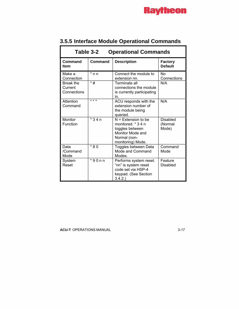
ACU-T OPERATIONS MANUAL 3-17
3.5.5 Interface Module Operational Commands
Table 3-2 Operational Commands Command Item
Command Description Factory Default
Make a Connection
* n n Connect the module to extension nn.
No Connections
Break the Current Connections
* # Terminate all connections the module is currently participating in.
N/A
Attention Command
* * * ACU responds with the extension number of the module being queried.
N/A
Monitor Function
* 3 4 n N = Extension to be monitored. * 3 4 n toggles between Monitor Mode and Normal (non-monitoring) Mode.
Disabled (Normal Mode)
Data /Command Mode
* 8 0 Toggles between Data Mode and Command Modes.
Command Mode
System Reset
* 9 0 n n Performs system reset. “nn” is system reset code set via HSP-4 keypad. (See Section 3.4.2.)
Feature Disabled

3-18 ACU-T OPERATIONS MANUAL
3.5.5.1 Make a Connection When the command * n n is entered at the HSP-4 keypad or these DTMF characters are detected in the audio input of any interface module, a connection is made between that module and the communications medium at extension n n. For example, if a VHF radio is wired to a DSP-1 module installed at extension slot #2, the command * 0 2, entered into the keypad of a telephone set associated with an LP-1 module at extension slot #4, will connect the local phone set to the VHF radio. The local phone user will hear the distant radio user’s transmit audio via the radio attached to the DSP-1 module. When the VOX in the LP-1 detects voice, the local phone user’s speech will be transmitted to the radio user. If a PSTN module is installed at extension slot #5, the command * 0 5 will connect the LP-1 user to the telephone line wired to that PSTN module. Voice prompts guide the LP-1 operator to enter the telephone number that will be called, and provide other useful information, such as informing the user if a module is busy or otherwise unavailable. To make a conference call among several modules, add a second connection after the first is made. An example is making a conference call between the LP-1 user at extension 04, the VHF radio at extension 02, and a PSTN subscriber via the PSTN module at extension 05. Make a connection between the LP-1 and the VHF radio as described above, then add the PSTN subscriber by entering * 0 5 and following the instructions provided.
3.5.5.2 Break a Connection To disconnect an interface module from any connection, enter the disconnect command * # (star pound). If the interface module is currently engaged in a conference call between several different modules, the * # sequence entered at the keypad of a radio associated with an DSP-1 module will remove the DSP-1 user from the call, but leave the remaining connections intact. Because of the way a telephone set is directly wired to the ACU-T chassis, it’s possible to terminate an LP-1 connection by hanging up the LP-1 telephone handset. All other modules require the * # entry to break a connection.
ACU-T OPERATIONS MANUAL 3-19
3.5.5.3 Attention Command When the Attention Command * * * is sent to any module, a voice prompt will be returned identifying the extension number of the module receiving the Attention Command. This can be done whether or not the module being queried is currently connected, so it can be used to check if the system is operational without having to make a connection.
3.5.5.4 Monitor Function This command enables any module to monitor all audio from any other module. Enter * 3 4 n, where n is the extension to be monitored. To discontinue monitoring, re-enter * 3 4 n, where n is the extension that is currently being monitored. This command toggles the selected module, turning the module function on, and then cutting it off. When the monitor function is enabled, the monitoring module will hear both transmit and receive audio of the module being monitored. The Monitor Function does not allow the monitoring module to assert any control over the monitored module. The monitoring module will still be capable of making connections and perform other functions if desired.
3.5.5.5 Data / Command Modes When an ACU-T interface module detects DTMF in its receive audio, it can either interpret the DTMF tone as a command input (Command Mode) or transmit DTMF via a connected PSTN-1 module so this DTMF can control other equipment (Data Mode). When in the Data mode, the DTMF input is detected and interpreted. This information is passed to the connected PSTN-1 module, which then regenerates the DTMF and inserts it into the PSTN-1 audio output. This regenerated DTMF is free of any FM noise or the frequency response related distortion that often results from the pre-emphasis and de-emphasis of FM audio circuits. The * 8 0 command toggles a module in and out of the Data Mode. All modules begin operation in the default Command Mode. When the Data/Command operational command is received, the module switches to the Data Mode and returns the prompt “Data Mode”. Whenever the * 8 0 command is again received, the module responds with the “Command Mode” prompt and reverts to normal operation.

3-20 ACU-T OPERATIONS MANUAL
A simple example of the use of this command assumes the radio user wants to call home and check the messages on his answering machine. The user makes a connection from the DSP-1 module associated with his radio to the PSTN module at extension 05. Following the voice prompts provided, he then enters the telephone number at his home. After the call is successfully made, the user then enters the * 8 0 command. Once he does so, he may enter the password to gain access to his home answering machine. All subsequent DTMF entries will result in the regeneration of the DTMF characters until he either toggles back out of the Data Mode with another * 8 0 entry or disconnects with a * # entry. The module that’s receiving the DTMF should also have its DTMF Mute Timer enabled (see the DTMF Mute Timer explanations in Section 2.11).
It is important to note that only the PSTN-1 module regenerates DTMF in this way. The Data Mode was created mainly to allow an ACU-T user to gain access to the system through any type of module (including the HSP-4), make a connection to a PSTN-1 module and be able to control equipment that commonly uses DTMF signaling (voice mail systems, answering machines, etc). Iit is possible, but not advisable, to use the Data Mode (with the DTMF Mute Timer disabled) to cause input DTMF to be repeated through the ACU-T. This is because of the FM noise that will be mixed with the DTMF, along with the frequency response related distortion that will be compounded by the fact that the DTMF will be repeated through two radios.
3.5.5.6 System Reset Feature The System Reset Feature allows a user who is interfaced with the system via a DSP-1 or PSTN-1 module to reset the ACU-T to its initial power-up state. This means all current connections will be lost, and the unit will return to any connections stored by HSP-4 using the * 3 6 command (see Table 3-1). In order to prevent any inadvertent or unauthorized use of this powerful feature, the System Reset Feature can only be used after first being enabled at the HSP-4 keypad. In addition, a “system reset code” is entered, and DSP-1 or PSTN-1 users must enter this code in order to implement this feature.

ACU-T OPERATIONS MANUAL 3-21
The ACU-T factory default for this feature is “disabled”. To enable System Reset capability, use the HSP-4 keypad to enter * 9 0 n n, where “n n” is any pair of digits other than 00. The feature is then enabled, and “n n” is the system reset code. If a DSP-1 or PSTN-1 user (who is currently connected to the system) enters the DTMF command * 9 0 n n, the system will be reset. If * 9 0 and any digits other than the system reset code are entered, the system will not be reset.
To disable this feature, enter * 9 0 0 0 at the HSP-4 top panel keypad. To re-enable, once again enter * 9 0 n n, where “n n” can be either the previous system reset code or an entirely new code.
3.6 PIN Security It’s possible to enable ACU-T access security features that require a correct PIN (Personal Identification Number) to be entered before a user can make a connection and thereby gain access to the system. This section explains the two different PIN security modes (Priority Operation and Exclusive Operation) and lists how to set-up and use both of these modes.
3.6.1 How PIN Security Works • When PIN numbers are enabled, the ACU-T extensions may be
programmed for various security levels, from 0 to 9. An extension set to security level 0 is available to all system users, without regard to PIN numbers. The ACU-T will not ask the user to input a PIN when a connection is requested to an extension set to security level 0.
• When PIN numbers are entered into the ACU-T database, they are assigned a security level. This security level corresponds to the extension security levels and identifies which extensions can be accessed via the PIN number.
• When a user tries to connect to a secure extension (an extension that has a security level above 0) he will be prompted “ENTER ID”. The user must enter his PIN at this time. If the security level of the PIN is not correct to provide access, the “SECURITY VIOLATION” voice prompt will be heard, and the connection will not be made. If the security level is correct, the connection will be allowed and the ACU-T will make the requested connection; when successful, the normal prompt will be heard: “n n CONNECTED”, where n is the requested extension number.

3-22 ACU-T OPERATIONS MANUAL
3.6.2 PIN Security Modes There are two modes of security operation, Priority and Exclusive. The two modes are independent of each other; the ACU-T is in either the Priority mode, or the Exclusive mode. It is not allowed to have some modules in the ACU-T set to Priority, and some set to Exclusive.
3.6.2.1 Priority Operation Mode Access is granted if the PIN security level is equal to or higher than the security level of the extension. Higher security levels are more secure; a PIN at security level 6 can access any extension set to level 6 and lower, but may not access extensions set at security levels 7, 8, or 9.
3.6.2.2 Exclusive Operation Mode Access is granted only if the PIN security level is equal to the security level of the extension to which the user is requesting to be connected. A PIN at security level 6 will allow the user to make a connection with an extension slot set to level 6, but not to any extension slot with security levels from 1 to 5 or 7 to 9. Remember also that access to extensions set to security level 0 does not require PIN numbers.
3.6.3 How to enable PIN Security • Enter “SETUP MODE” * 9 9.
• To enable Priority Mode PIN numbers enter * 2 9 1, and listen for the “READY” prompt. To instead enable Exclusive Mode PIN numbers enter * 2 9 2.
• To disable PIN numbers (either mode) enter * 2 9 0, and listen for the “READY” prompt.
• To save the configuration enter * #, and listen for prompt “SAVING CONFIGURATION”, followed by “CONFIGURATION HAS BEEN SAVED” after the ACU-T has completed storing all system parameters.

ACU-T OPERATIONS MANUAL 3-23
3.6.4 How to Set ACU-T Security Levels • Enter “SETUP MODE” by pressing * 9 9.
• Select the extension to be programmed. For example, to program the module at extension 05 enter * 0 1 0 5, and listen for the “READY” prompt.
• Now enter the security level * 3 2 n, where n is the level from 0 to 9. The higher the number the more secure. Listen for the “READY” prompt. For example: to set a security level of five, enter the command * 3 2 5.
• Repeat the two previous steps as often as necessary to assign security levels to any remaining extensions that should have a security level higher than the default level 0.
To save the configuration enter * # and listen for prompt “SAVING CONFIGURATION”, followed by “CONFIGURATION HAS BEEN SAVED”.
3.6.5 How to Input PIN Numbers into the ACU-T Database
• Enter the “SETUP MODE” by entering * 9 9.
• PIN numbers are entered into a database for the ACU-T globally; therefore, it is not necessary to select a particular extension.
• Enter the “Program PIN” command * 3 0 n n n n x, where n n n n is the four digit pin and x is the desired security level of the PIN from 0 to 9. Example: if the PIN chosen is 1234 and the associated security level desired is 8, enter the command * 3 0 1234 8 and listen for the “READY” prompt.
• Repeat the previous step as necessary to input all PIN numbers to be used by the system.
• To save the configuration enter * #, and listen for prompt “SAVING CONFIGURATION’, followed by “CONFIGURATION HAS BEEN SAVED”.

3-24 ACU-T OPERATIONS MANUAL
3.6.6 How to Delete PIN Numbers from the Database
• Enter “SETUP MODE” with * 9 9.
• Enter the DELETE PIN command * 3 1 n n n n, where n n n n is the four digit number of the PIN to be deleted.
To save configuration enter * #, listen for prompt “SAVING CONFIGURATION”, followed by “CONFIGURATION HAS BEEN SAVED”.
3.6.7 How To Use The Pin Security Feature • Input security levels for each of the ACU-T extensions. If a security
level is not entered, that extension will have the factory default of 0 (see Section 3.6.4 above).
• Input PIN numbers into the database (see Section 0 above).
• Enable PIN security in either the Exclusive or the Priority mode (see Section 3.6.2 above).
• PIN security will now be functioning. Users without correct PIN numbers will not be able to access any extension that has a security level above 0.

ACU-T OPERATIONS MANUAL 3-25
3.7 ACU-T Operation Basic operation and control of the ACU-T are discussed in the following paragraphs. These instructions assume the ACU-T has already been correctly configured per Section 2. Scenarios assume most configuration options are at default settings. If not, there may be some changes in how the scenarios progress .
3.7.1 Unit Power-Up Prior to initial power-up, ensure the ACU-T has proper power applied, either by a fully charged +12 VDC battery or by using the AC to DC power module provided. This will be indicated by LED indication at the top of the module by either the Power On LED or Charger On LED. The ACU-T will run internal start-up tests, ensure all modules installed have correct revision software installed, and then begin operation. If incorrect revision software is detected in any one of the modules installed, the module’s front panel LEDs will flash from bottom to top.

3-26 ACU-T OPERATIONS MANUAL
3.7.2 Basic Operation Scenarios Refer to Figure 3-1 when studying the following operational scenarios.
HSP-400EXT
INTERFACE MODULESCPM-201 02 03 04 05
ACU-TTACTICAL INTERCONNECT
01 02 03 04 05
FAULTFAULT
SIGNALSIGNAL
PTT PTT
FAULTFAULT
CONNECTSIGNAL
PTT VOX
COR COR
L1
L2
COR
DSP-1
MON
DSP-1
MON
PSTN-1DSP-1
MON MON
RING
SLAVE
FAULT
MASTER
CPM-2
CPM-2
LOCAL OPERATORUSER "A" (radio band 1)
PSTN USER
USER "B" (radio band 2)
HANDSET
PHONES
FAULT
PTT
HSP-4
VOX
FAULT
P2
MON
RING
P1
LP-1
OFF HOOK
LOCAL PHONE CONNECTION
HSP-4
Figure 3-1 Pictorial Layout for Operating Scenarios
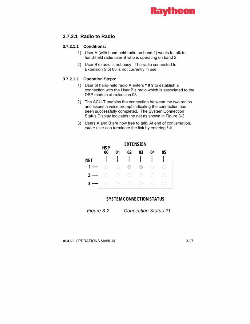
ACU-T OPERATIONS MANUAL 3-27
3.7.2.1 Radio to Radio
3.7.2.1.1 Conditions: 1) User A (with hand held radio on band 1) wants to talk to
hand-held radio user B who is operating on band 2.
2) User B’s radio is not busy. The radio connected to Extension Slot 03 is not currently in use.
3.7.2.1.2 Operation Steps: 1) User of hand-held radio A enters * 0 3 to establish a
connection with the User B’s radio which is associated to the DSP module at extension 03.
2) The ACU-T enables the connection between the two radios and issues a voice prompt indicating the connection has been successfully completed. The System Connection Status Display indicates the net as shown in Figure 3-2.
3) Users A and B are now free to talk. At end of conversation, either user can terminate the link by entering * #.
NET
SYSTEM CONNECTION STATUS
EXTENSION
2
3
1
01HSP00 0302 04 05
Figure 3-2 Connection Status #1

3-28 ACU-T OPERATIONS MANUAL
3.7.2.2 PSTN to Radio
3.7.2.2.1 Conditions: 1) PSTN user wants to talk to hand-held radio User A.
2) User A’s radio is not busy.
3.7.2.2.2 Operation Steps: 1) PSTN user calling from distant phone via the public
telephone network dials the phone number associated with the ACU-T's PSTN-1 module.
2) ACU-T greets the PSTN caller and prompts him to enter the “star” and two-digit number of the extension that caller would like to converse with. In our example, User A resides at extension 02, so PSTN caller enters * 0 2.
3) The ACU-T enables the connection to the radio and issues the voice prompt “02 CONNECTED” to the PSTN caller indicating the connection has been successfully completed.
4) PSTN caller and User A talk. At end of conversation, either user can terminate the link by entering * #. In links involving more than two modules, all users should terminate the link by using * #.
NET
SYSTEM CONNECTION STATUS
EXTENSION
2
3
1
01HSP00 0302 04 05
Figure 3-3 Connection Status #2

ACU-T OPERATIONS MANUAL 3-29
3.7.2.3 Local Operator to Radio
3.7.2.3.1 Conditions: 1) Local operator wants to talk over band 1 to hand-held radio
User A.
2) User A’s radio is not busy.
3.7.2.3.2 Operation Steps: 1) The Local Operator (using HSP-4 handset and keypad)
enters * 0 2 to link with User A.
2) The ACU-T makes the connection between the local operator and the band 1 radio, then issues the voice prompt “02 CONNECTED”.
3) Local operator and User A talk. At end of conversation, either user can terminate the link by entering * #. Note: In links involving more than two modules, a users who enters * # only removes himself from the link.
3.7.2.4 Radio to Local Operator
3.7.2.4.1 Conditions: 1) Hand-held radio User A wants to talk to local operator at the
ACU-T.
3.7.2.4.2 Operation Steps: 1) The Local Operator Extension number is '00', so hand-held
radio User A enters * 0 0 on his DTMF keypad.
2) The ACU-T enables the connection between the radio the local operator and issues the “00 CONNECTED” voice prompt to User A, indicating the connection has been successfully completed.
3) User A can be heard at the HSP-4 speaker and handset. User A and local operator talk. At end of conversation, either user can terminate the link by entering * #.
The System Connection Status Display as shown below is the same whether the call is initiated by the radio user or by the local operator.

3-30 ACU-T OPERATIONS MANUAL
NET
SYSTEM CONNECTION STATUS
EXTENSION
2
3
1
01HSP00 0302 04 05
Figure 3-4 Connection Status #3
ACU-T OPERATIONS MANUAL 3-31
3.7.2.5 Radio to PSTN
3.7.2.5.1 Conditions: 1) Hand-held radio User A wants to be connected to PSTN and
make call to 555-1234.
2) PSTN module is not busy, and phone at 555-1234 is not busy.
3.7.2.5.2 Operation Steps: 1) PSTN-1 Module Extension number is '05', so User A enters
* 0 5 on keypad.
2) The ACU-T prompts the user A to “ENTER PHONE NUMBER”.
NOTE: All phone number entries must be terminated by the # key, so the ACU-T can determine the end of the number.
3) User enters 5 5 5 1 2 1 2 #, and the ACU-T PSTN-1 module initiates the call. Prompts advise User A of the progress in making the call. When the link is established, the phone at 555-1212 rings.
4) User A and the person he's called on telephone now talk. At end of conversation, either user can terminate the link by entering * #. In links involving more than two modules, all users should terminate the link by using * #.
NOTE: If no one answers the telephone, the attempt to connect will be terminated when the set Ringing Time expires (Factory default setting is 30 seconds).

3-32 ACU-T OPERATIONS MANUAL
3.7.2.6 Local Phone to Radio
3.7.2.6.1 Conditions: 1) Local Phone user wants to talk to hand-held radio User B.
2) User B’s radio is not busy.
3.7.2.6.2 Operation Steps: 1) Local Phone user picks up handset and hears dial tone.
User B resides at extension 03, so Local Phone user enters * 0 3.
2) The ACU-T enables the connection to the radio and issues the “03 CONNECTED” voice prompt to the Local Phone user.
3) Local Phone User and User B talk. At end of the conversation, either user can terminate the link by entering * #.
The figure below shows the System Connection Status display during this conversation.
NET
SYSTEM CONNECTION STATUS
EXTENSION
2
3
1
01HSP00 0302 04 05
Figure 3-5 Connection Status #4

ACU-T OPERATIONS MANUAL 3-33
3.7.2.7 Conference Call
3.7.2.7.1 Conditions: 1) Local Operator has already established a conversation with
hand-held radio user A (see Section 3.7.2.3). He now wants to turn the conversation into a conference call with a third party located at telephone number 555-1234.
2) PSTN module is not busy, and phone at 555-1234 is not busy.
3.7.2.7.2 Operation Steps: a) PSTN-1 Module Extension is '05', so local operator enters * 0 5 on
the HSP-4’s keypad on the top panel of the ACU-T.
b) The ACU-T then prompts the local operator to “ENTER PHONE NUMBER”. Note: all phone number entries must be terminated by the # key, so the ACU-T can determine the end of the number.
c) Local operator enters 5 5 5 1 2 3 4 #, and the ACU-T PSTN-1 module initiates the call. Prompts are given to the local operator advising him of the progress in making the call. (For example if the line is busy or there is no answer, the caller is informed.) When the link is established, ACU-T sends ringback audio to Local Operator and User A until the phone is answered.
d) All users can now converse & be heard.
e) Additional parties can be added to the call if required.
f) Any user can terminate his connection to the link by entering * #; all other connections will be maintained. When only two parties remain in the conference call, and either of these users enter * #, the link will be terminated.
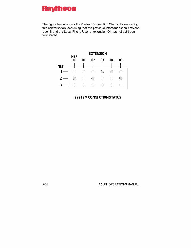
3-34 ACU-T OPERATIONS MANUAL
The figure below shows the System Connection Status display during this conversation, assuming that the previous interconnection between User B and the Local Phone User at extension 04 has not yet been terminated.
NET
SYSTEM CONNECTION STATUS
EXTENSION
2
3
1
01HSP00 0302 04 05

ACU-T OPERATIONS MANUAL 3-35
3.8 SERIAL Remote Control (RS-232) The ACU-T may be controlled and monitored remotely via its RS-232 interface. We offer the ACU Controller software that runs under Windows 95/98, NT, or XP on a PC and controls the ACU-T system. The software is the easiest way to check and modify module setups. This software is currently supplied free of charge with new systems; an upgrade kit can be ordered to use the ACU Controller with older systems that were shipped prior to its completion. Consult us for details regarding the purchase of an ACU Controller upgrade kit or for RS-232 protocol information if you wish to create your own remote control application.
3.9 Removal and Replacement of Modules The ACU-T Modules can be "Hot-Plugged"; they can be removed and inserted while the unit's main power is on without resulting in damage. If a module that is presently communicating with a second module is removed, that link will be lost. If the CPM-2 module is removed, all system operation ceases and the new CPM-2 module must be reconfigured. The CPM-2 will not be damaged by the Hot Swapping process; however, the power must then be turned on and off to reboot the CPM-2. Therefore, it is advised to turn the power off when replacing the CPM-2.

3-36 ACU-T OPERATIONS MANUAL
End of Section 3
ACU-T OPERATIONS MANUAL 4-1
4 ACU-T Technical Information
4.1 Scope This section contains technical information for the ACU-T system and its various plug-in modules. Specifications and block diagrams are provided for each of the interface modules. This information is intended to provide a basic understanding of each module to allow troubleshooting to the module level and to allow the development of applications for the ACU-T.
4.2 General Description Raytheon’s ACU-T system is the “tactical” version of the ACU-1000. It’s a transportable, modular interface/interconnect system packaged in a Eurocard chassis modified for improved protection from the elements. With this product, an intelligent interconnect system can be configured to meet almost any interface application involving telephones and radios of any sort. The ACU-T system is suitable for HF, LMR, Nextel, and Satcom systems and offers essentially unlimited applications and expandability. A system consists of a chassis, backplane, top panel, modules, module software and system control software.
4.3 Card Cage and Backplane The Card Cage is a 6.25" wide transportable Eurocard cage equipped with a backplane board that the modules are plugged into. A DC input module and battery power system is located at the back of the module. The DC module is a combination DC line filter, power cable connector, input voltage selector and fuse holder. The backplane interfaces the outside world via circular plastic CPC connectors, and internally to the plug-in modules via 60-pin card edge connectors. No active or passive electrical components reside on the backplane board.
4-2 ACU-T OPERATIONS MANUAL
4.4 CPM-2 Control Processor Module The ACU-T Control Processor Module has an 80186 processor with one MB of flash EPROM that stores the operating software for the ACU and controls the entire chassis via an internal high-speed serial bus. It requests and receives status and information from each module and sends commands to each module, and instructs modules to connect to one or more of the sixteen audio buses on the ACU backplane. The CPM provides an RS-232 serial port allowing programming and monitoring of all ACU-T functions via an external computer or serially interfaced console. The front panel of the CPM Module contains a Fault LED, along with Master and Slave LEDs that indicate the unit's status in an expanded system.

ACU-T OPERATIONS MANUAL 4-3
4.5 HSP-4 Handset/Speaker Module
4.5.1 General Description HSP-4 The HSP-4 Module provides a means to locally monitor, configure and control an ACU-T system. The user can monitor audio via an internal speaker, plug in external headphones, or use the handset that comes with the HSP-4. The handset includes a PTT switch so the user can key an associated radio from the HSP-4. Module control and configuration is via a 3x4 keypad on the top panel (standard telephone layout) that enables the user to select a module in the system and enter control/configuration data. For example, if the system contains a PSTN-1 module, the user may place telephone calls manually using the HSP-4 keypad and handset.
In addition to the front-panel handset and phones jacks, the HSP-4 has an audio line (0 dBm nominal) input and output, and external microphone input and external speaker output. There are three uncommitted auxiliary parallel inputs and three uncommitted auxiliary parallel outputs.

4-4 ACU-T OPERATIONS MANUAL
4.5.2 Block Diagram Description HSP-4 (Refer to Error! Reference source not found.)
The HSP-4 contains its own microprocessor that performs all the local control of the module. It communicates with the system’s CPM-2 module over the control and data buses on the main chassis backplane via I/O latches and drivers U14 through U17. The microprocessor referred to in this description is the local one on the HSP-4 module.
The HSP-4 houses a plug-in voice prompt generator board, which receives its instructions from the system CPM-2 via the microprocessor on the HSP-4 board. The voice prompt generator routes its prompts audio over one of the system audio buses via audio gates U14 through U17.
Another function of the HSP-4 module is to connect four-wire speaker and microphone audio to the 16-line audio bus structure on the ACU main chassis backplane board. Microphone audio is routed to the audio buses by audio gates U1 through U4, and speaker audio is brought in from the audio buses by audio gates U5 through U8. These audio gates are controlled directly by audio bus latches U19 through U22, which receive their instructions directly from the microprocessor on the HSP-4. The microprocessor, in turn, receives its instructions from the system CPM-2 module via I/O latches and drivers U16 through U18. Thus, the connections to and from any audio bus are controlled ultimately by the CPM-2 module, which decides which buses to assign to the HSP-4 module depending on a number of system parameters. The CPM-2 passes connect information to the HSP-4 microprocessor, which controls the audio gates.
Audio from an interconnected interface module is picked off of the ACU-T backplane and inserted on one of the HSP-4 audio buses. Next, it’s routed to the speaker output through amplifier U10A then through speaker driver U11, where the output volume is set by pot R72. Monitor output audio is routed to the back panel connector via amplifier U10B at a fixed zero dBm level. Microphone audio is routed through preamp U12A, through an AGC circuit, then through amplifier U14B onto an audio bus through audio gates U1 through U4. A line-level audio input is mixed into the input of U14B.

ACU-T OPERATIONS MANUAL 4-5
The /AuxO1, /AuxO2, and /AuxO3 digital outputs are generated by transistors Q1, Q2 and Q3 which are driven by the microprocessor. Digital inputs /AuxI1, /AuxI2, and /AuxI3 are routed to gates U44C, U44D, and U44E, which are read by the microprocessor.
The top-panel mounted keypad, interfaced to the HSP-4 microprocessor allows the user to enter system commands and programming parameters. The microprocessor then formats the keypad data and sends it to the system’s CPM-2 for action.
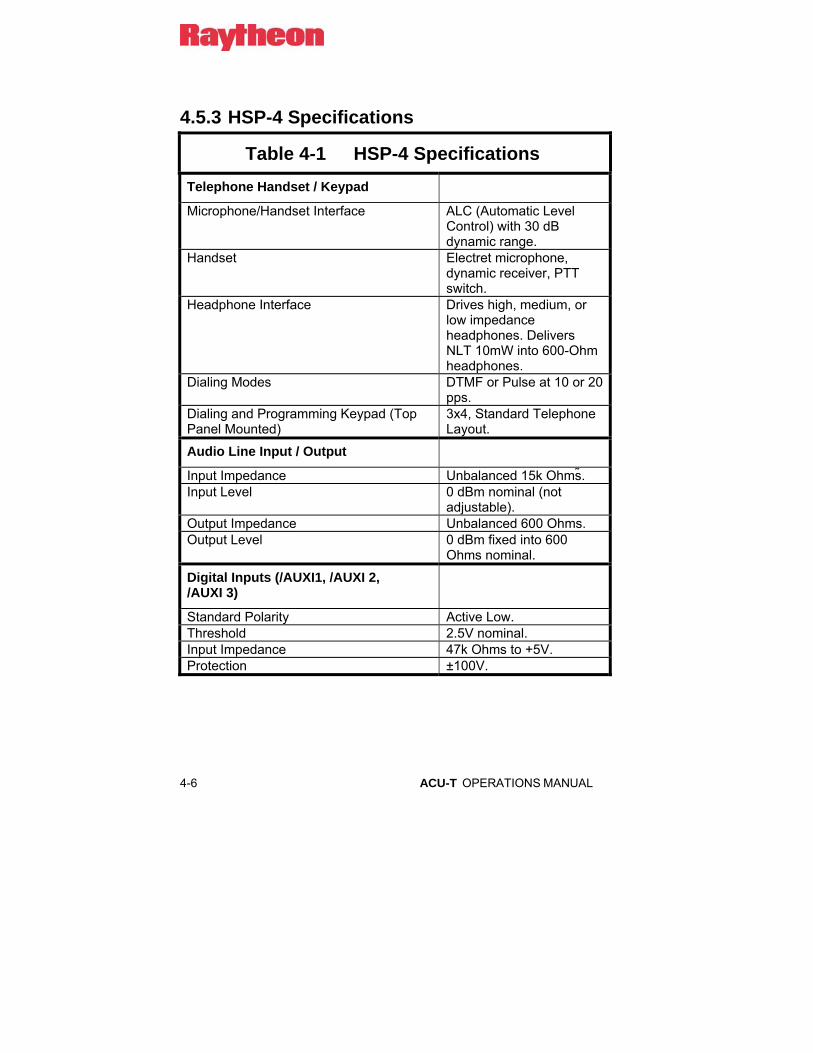
4-6 ACU-T OPERATIONS MANUAL
4.5.3 HSP-4 Specifications
Table 4-1 HSP-4 Specifications Telephone Handset / Keypad
Microphone/Handset Interface ALC (Automatic Level Control) with 30 dB dynamic range.
Handset Electret microphone, dynamic receiver, PTT switch.
Headphone Interface Drives high, medium, or low impedance headphones. Delivers NLT 10mW into 600-Ohm headphones.
Dialing Modes DTMF or Pulse at 10 or 20 pps.
Dialing and Programming Keypad (Top Panel Mounted)
3x4, Standard Telephone Layout.
Audio Line Input / Output
Input Impedance Unbalanced 15k Ohms . Input Level 0 dBm nominal (not
adjustable). Output Impedance Unbalanced 600 Ohms. Output Level 0 dBm fixed into 600
Ohms nominal.
Digital Inputs (/AUXI1, /AUXI 2, /AUXI 3)
Standard Polarity Active Low. Threshold 2.5V nominal. Input Impedance 47k Ohms to +5V. Protection ±100V.
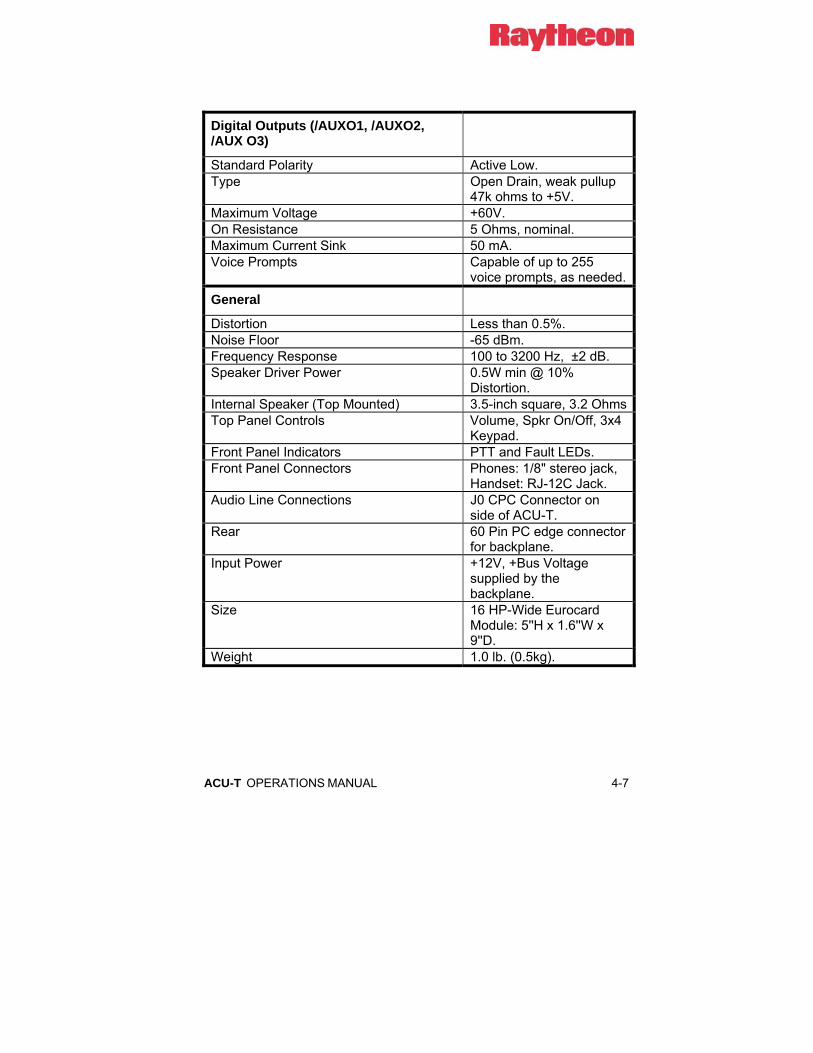
ACU-T OPERATIONS MANUAL 4-7
Digital Outputs (/AUXO1, /AUXO2, /AUX O3)
Standard Polarity Active Low. Type Open Drain, weak pullup
47k ohms to +5V. Maximum Voltage +60V. On Resistance 5 Ohms, nominal. Maximum Current Sink 50 mA. Voice Prompts Capable of up to 255
voice prompts, as needed.
General
Distortion Less than 0.5%. Noise Floor -65 dBm. Frequency Response 100 to 3200 Hz, ±2 dB. Speaker Driver Power 0.5W min @ 10%
Distortion. Internal Speaker (Top Mounted) 3.5-inch square, 3.2 Ohms Top Panel Controls Volume, Spkr On/Off, 3x4
Keypad. Front Panel Indicators PTT and Fault LEDs. Front Panel Connectors Phones: 1/8" stereo jack,
Handset: RJ-12C Jack. Audio Line Connections J0 CPC Connector on
side of ACU-T. Rear 60 Pin PC edge connector
for backplane. Input Power +12V, +Bus Voltage
supplied by the backplane.
Size 16 HP-Wide Eurocard Module: 5''H x 1.6''W x 9''D.
Weight 1.0 lb. (0.5kg).

4-8 ACU-T OPERATIONS MANUAL
4.6 DSP-1 Module
4.6.1 General Description DSP-1 The DSP-1 module is a 4-wire interface module used to interface radios and other 4-wire devices. It contains three types of COR sensing: hardwired signal, VMR, and VOX. It offers a DSP noise reduction mode. Its VMR and noise reduction capability make it an ideal interface for HF radios.
4.6.2 Block Diagram Description DSP-1 (Refer to Figure 4-2 Error! Reference source not found.)
The DSP-1 contains a DSP processor that performs all of the local control of the module. It communicates with the system’s CPM-2 module over the control and data buses on the main chassis backplane via I/O latches and drivers U14 through U17.
One function of the DSP-1 module is to connect four-wire transmit and receive audio to the 16-line audio bus structure on the ACU main chassis backplane board. Receive audio is routed to the audio buses by audio gates U1 through U4, and transmit audio is brought in from the audio buses by audio gates U5 through U8. These audio gates are controlled directly by audio bus latches U10 through U13, which receive their instructions directly from the DSP processor on the DSP-1. The DSP-1, in turn, receives its instructions from the CPM-2 module in the system via I/O latches and drivers U14 through U17. Thus, the connections to and from any audio bus are controlled ultimately by the CPM-2 module, which decides which buses to assign to the DSP-1 module depending on a number of system parameters. The CPM-2 passes connect information to the DSP processor on the DSP-1, which controls the audio gates.

ACU-T OPERATIONS MANUAL 4-9
Audio from an audio bus is routed to the transmit output through amplifier U10A then through amplifier U10B, where the output level is set by digital pot U13. Receive audio in is routed through amplifier U11A then through amplifier U11B, which is gain-controlled by digital pot U13 and into the DSP A/D input. The DSP-1 processes the audio and outputs its signal onto an audio bus through audio gates U1 through U4. The DSP processor also runs a DTMF receiver, which decodes the DTMF digits that may come in from a receiver and passes them digitally on to the system’s CPM-2 for processing. Under instructions from the CPM-2, the DSP-1 generates DTMF signals, which are routed to the transmit output through amplifier U10B.
The /PTT, /AuxO1, and /AuxO2 digital outputs are generated by transistors Q1, Q2 and Q4 which are driven by the DSP. Digital inputs /COR, /AuxI1 and /AuxI2 are routed to gates U24A, U24B, and U24D, which are read by the DSP.
An RS-232 interface chip, U25, changes RS-232 voltage levels into TTL voltage levels for processing by the DSP module (not supported in current software).

4-10 ACU-T OPERATIONS MANUAL
4.6.3 DSP-1 Specifications
Table 4-2 DSP-1 Specifications RX Audio Input
Input Impedance Balanced /Unbalanced 600 Ω; Unbalanced 47kΩ.
Input Level -26 to +12 dBm, programmable. Frequency Response 100 Hz to 3200 Hz ±2 dB.
TX Audio Output
Output Impedance Balanced or Unbalanced 600Ω. Output Level -26 to +12 dBm, programmable. Frequency Response 100 Hz to 3200 Hz ± 2dB. Distortion Less than 0.5%. Noise Floor -65 dBm.
VOX/VMR
VOX/VMR Thresholds
Low, MED1, MED2, High; Programmable.
VOX Hangtime 175 ms to 1.575 sec; Programmable in 200 ms steps.
VMR Hangtime 775 ms to 1.575 sec; Programmable in 200 ms steps.
Audio Delay, VOX and COR Modes
20 ms to 300 ms; Programmable in 40 ms steps.
Audio Delay, VMR Mode
220, 260, or 300 ms; Programmable.
Transmit Key Tones None, 1950 Hz, or EIA keying sequence; Programmable.
Equalizer
Cut Settings at 3 kHz 5 dB, 3.5 dB, 2dB, 0 dB; Programmable. Boost Settings at 3 kHz
5 dB, 3.5 dB, 2 dB, 0 dB; Programmable.
Time Domain DSP Noise Reduction
Eight programmable levels.
Digital Inputs
COR Input Polarity Active Low or Active High, Programmable.

ACU-T OPERATIONS MANUAL 4-11
Table 4-2 DSP-1 Specifications AUX Inputs Polarity Active Low. Threshold 2.5V nominal. Input Impedance 47kΩ to +5V. Protection ±100V. Digital Outputs
Standard Polarity Active Low. Type Open Drain, weak pull-up 47kΩ to +5V. Maximum Voltage +60V. On Resistance 5 Ω nominal. Maximum Current Sink
50 mA.
General
Front Panel Monitor, Signal, COR, PTT, and Fault LEDs. Rear 60 Pin PC edge connector for backplane. Audio Line Connections
J1 to J5 CPC Connectors on side of ACU-T.
Input Power ±12V, +Bus Voltage supplied by the backplane.
Size 5’’H x 0.8’’W x 9’’D. Weight 1lb. (0.5kg).
4-12 ACU-T OPERATIONS MANUAL
4.7 PSTN-1 Module
4.7.1 General Description PSTN-1 The PSTN Module is the 2-wire interface between the ACU system and a telephone system (as opposed to a telephone set). A telephone system is an entity that accepts dialing information and processes calls, such as a PSTN line, PABX line, Inmarsat Terminal, or cellular phone. (A telephone set is a device that generates dialing information. It is interfaced to the ACU system via the LP-1 Module.) The PSTN-1 contains one 4-wire port for interfacing to 4-wire phone lines or other devices, and two 2-wire ports with front-panel RJ-11C jacks for interfacing with PSTN lines or satellite equipment. The module contains ring detect circuitry. The interface signal levels are programmable via the HSP-4 module.
The module has a DSP hybrid and VOX with programmable sensitivity and hangtime. It has a DTMF receiver/generator for control and call progress recognition. There are two uncommitted auxiliary parallel inputs and two uncommitted auxiliary parallel outputs. The two 2-wire ports are permanently connected to front-panel RJ-11C jacks, but may be routed to the backplane connector by means of internal jumpers. The side panel connections are useful when no front-panel connections are wanted in a system.
4.7.2 Block Diagram Description PSTN-1 (Refer to Figure 4-3Error! Reference source not found.)
The PSTN-1 contains its own small, plug-in DSP module that does all of the local control of the PSTN-1 module as well as running hybrid, call progress, and DTMF algorithms. It communicates with the system’s CPM-2 module over the control and data buses on the main chassis backplane via I/O latches and drivers U14 through U17. In the following description, the DSP module referred to is the one located on the PSTN-1 module itself, not a DSP-1 Module in the ACU-T system.

ACU-T OPERATIONS MANUAL 4-13
The function of the PSTN-1 module is to connect telephone line send tand receive audio to the 16-line audio bus structure on the ACU main chassis backplane board. Receive audio is routed to the audio buses by audio gates U1 through U4, and send audio is brought in from the audio buses by audio gates U5 through U8. These audio gates are controlled directly by audio bus latches U10 through U13, which receive their instructions directly from the DSP module on the PSTN-1. The DSP module, in turn, receives its instructions from the CPM-2 module in the system via I/O latches and drivers U14 through U17. Thus, the connections to and from any audio bus are controlled ultimately by the CPM-2 module, which decides which buses to assign to the PSTN-1 module depending on a number of system parameters. The CPM-2 passes connect information to the DSP module on the PSTN-1, which controls the audio gates.
Audio from an audio bus is routed to the telephone line through amplifier U20A, where DTMF signals generated by the DSP module are mixed in, then routed through amplifier U20B, where the output level is set by gates U22, which are controlled by the DSP module. The four-wire output is driven by amplifier U24A, whose output level is set by the gain of U20B. Audio in from the telephone line is routed through amplifier U21B, which is gain-controlled by gates U25 (controlled by the DSP module) and into the DSP module A/D input. Four-wire input audio is routed through audio gate U27B, controlled by the DSP module. The DSP module may enable either the 4W input or the telephone input, but not both at the same time. The DSP module runs an adaptive hybrid, which outputs its signal through amplifier U23B and onto an audio bus through audio gates U1 through U4. The hybrid’s function is to separate the two-wire audio from the telephone line into four-wire send and receive audio paths from use by other modules in the ACU-T. The DSP module runs a DTMF receiver, which decodes the DTMF digits that may come in from the telephone line and passes them digitally on to the system’s CPM-2 for processing. Under instructions from the CPM-2, the DSP module generates DTMF dialing signals, which are routed to the telephone line through amplifier U20A.
Ring voltage on the telephone line is detected by U26, which informs the DSP module that a ring is being received. The DSP module can then operate hook relay K1, which closes to seize the telephone line and create an off-hook condition. Upon receiving a ring signal, the DSP activates ring tone generator U22/U23 at the incoming ring cadence, which generates an audible ring signal using the piezo audio transducer in the PSTN-1 module.
4-14 ACU-T OPERATIONS MANUAL
The /AuxO1 and /AuxO2 digital outputs are generated by transistors Q5 and Q6 which are driven by output latches U35 through U37. These latches, in turn, are driven by the DSP module. The /Aux01 and /AUX02 Digital Outputs can sink up to 50 mA. Digital inputs /AuxI1 and /AuxI2 are routed to gates U30D and U30E, which are read by the DSP module.
The Line 1 or Line 2 telephone line connections are selected by the line select relay, K2, which is operated by the DSP module under instructions from the system’s CPM-2 module. The L1 line can be accessed by the HSP-4 via DTMF, and by the Console Interface Software to dial out of the system. The ACU-T will auto-answer the L1 line connection when users are dialing into the unit. The L2 line can be accessed only by the Console Interface Software to dial out, and the L2 line does not auto-answer. The telephone line connections are permanently routed to the RJ-11C connectors on the front panel, but may be routed to pins in the side panel CPC connector by means of jumpers JP1 through JP4.

ACU-T OPERATIONS MANUAL 4-15
4.7.3 PSTN-1 Specifications
Table 4-3 PSTN-1 Specifications Telephone Line Interface
2-Wire Audio Interface
Phone line Input/Output Levels -24 to 0 dBm; Programmable in 3 dB steps.
Input/Output Impedance to Phone Line
600 Ω Nominal.
4-Wire Audio Input/Output
Input Impedance Unbalanced 10k Ω. Input Level Adjustable -18 to +6 dBm in
3 dB steps. Output Impedance Unbalanced 600 Ω. Output Level Adjustable -18 to +6 dBm in
3 dB steps.
2-Wire and 4-Wire Interfaces
Distortion Less than 0.5%. Noise Floor -65 dBm. VOX Thresholds Four selectable VOX thresholds of
19, 16, 13, and 10 dB below input level setting. The default setting is -16 dB (-25 dBm @ -9 dBm level setting, for example).
VOX Hangtime 0.5, 1.0, 1.5, or 2.0 Seconds; Programmable.
Hybrid Balance/Adaptation Speed
-30 dB over 300 to 3200 Hz BW within 1.25 seconds; measured with white noise source into 600 Ohms.
Ultimate Hybrid Balance -50 dB typical over 300 to 3200 Hz BW; measured with a single tone into 600 Ohms.
Hybrid Impedance Matching Capability
0 to infinite Ohm complex impedance.

4-16 ACU-T OPERATIONS MANUAL
Digital Inputs (/AUXI1, /AUXI 2)
Standard Polarity Active Low. Threshold 2.5V nominal. Input Impedance 47kΩto +5V. Protection ±100V.
Digital Outputs (/AUXO1, /AUXO2)
Standard Polarity Active Low. Type Open Drain, weak pull-up 47kΩ to
+5V. Maximum Voltage +60V. On Resistance 5 Ω nominal. Maximum Current Sink 50 mA.
General
Front Panel Monitor, Ring, Connect, VOX, and Fault LEDs.
Rear 60 Pin PC edge connector for backplane.
Input Power +12V, +Bus Voltage supplied by the backplane.
Size 4HP-Wide Eurocard Module: 5’’H x 0.8’’W x 9’’D.
Weight 1.0 lb. (0.5kg).

ACU-T OPERATIONS MANUAL 4-17
4.8 LP-1 Module
4.8.1 General Description LP-1 The Local Phone Module is the interface to the ACU system for 2-wire devices that generate dialing information such as a standard telephone set or FAX machine. This module contains a loop current generator, ring voltage generator, dial and busy tone generators, a DSP hybrid with VOX and a DTMF generator/receiver.
4.8.2 Block Diagram Description LP-1 (Refer to Error! Reference source not found.)
The LP-1 contains its own small, plug-in DSP module that does all of the local control of the LP-1 module as well as running hybrid, call progress, and DTMF algorithms. It communicates with the system’s CPM-2 module over the control and data buses on the main chassis backplane via I/O latches and drivers U14 through U17. In the following description, the DSP module referred to is the one located on the LP-1 module itself, not a DSP-1 Module in the ACU-T system.
The function of the LP-1 module is to connect telephone set send and receive audio to the 16-line audio bus structure on the ACU main chassis backplane board. Receive audio is routed to the audio buses by audio gates U1 through U4, and sendaudio is brought in from the audio buses by audio gates U5 through U8. These audio gates are controlled directly by audio bus latches U10 through U13, which receive their instructions directly from the DSP module on the LP-1. The DSP module, in turn, receives its instructions from the CPM-2 module in the system via I/O latches and drivers U14 through U17. Thus, the connections to and from any audio bus are controlled entirely by the CPM-2 module, which decides which buses to assign to the LP-1 module depending on a number of system parameters. The CPM-2 passes connect information to the DSP module, which controls the audio gates.

4-18 ACU-T OPERATIONS MANUAL
Audio from an audio bus is routed to the telephone set through amplifier U21A, where busy and dial tones generated by the DSP module are mixed in, and then routed through amplifier U21B, where the output level is set with jumper JP2. Audio in from the telephone set is routed through amplifier U22A, then through level set jumper JP3, enable jumper JP7, through amplifier U23B into the DSP module. Four-wire input audio is routed through level set jumper JP4 and through enable jumper JP8. Either the 4W input or the telephone input (or both at the same time) may be enabled by jumpers JP7 and JP8. The DSP module runs an adaptive hybrid, which outputs its signal through amplifier U23A and onto an audio bus through audio gates U1 through U4. The hybrid’s function is to separate the two-wire send/receive audio from the telephone set into four-wire send and receive audio paths from use by other modules in the ACU-T. The DSP module runs a DTMF receiver, which decodes the DTMF dialing digits generated by the telephone set and passes them digitally on to the system’s CPM-2 for processing. Under instructions from the CPM-2, the DSP module can generate DTMF signals, which are routed to the telephone set output through amplifier U21A.
Loop current is supplied to the telephone set by loop current generator Q4, which can generate a 20 mA or 50 mA loop current depending on the setting of jumper JP5. Transistor Q3 senses loop current draw to detect an off-hook condition, and passes this information to the DSP module.
Ring voltage is generated by U20, which supplies the ring voltage to the telephone set through ring relay K1, which operates at the ring cadence rate. The ring generator is turned on and off at the proper cadence by transistor Q2, which is controlled by the DSP module. The ring generator circuit detects an off-hook condition if it occurs during a ring cycle, and passes this information to the DSP module.
The /VOX, /AuxO1, and /AuxO2 digital outputs are generated by transistors Q6, Q7, and Q8 which are driven by output latches U35 through U37. The DSP module drives these latches, in turn. Digital inputs /PTT, /AuxI1, and /AuxI2 are routed to gates U26A, U26B, and U26D, which are read by the DSP module.
The line 1 or line 2 telephone set connections are selected by the line select relay, K2, which is operated by the DSP module under instructions from the system’s CPM-2 module. The telephone set connections are routed to the RJ-11C front panel connectors and to pins in the side panel CPC connector.
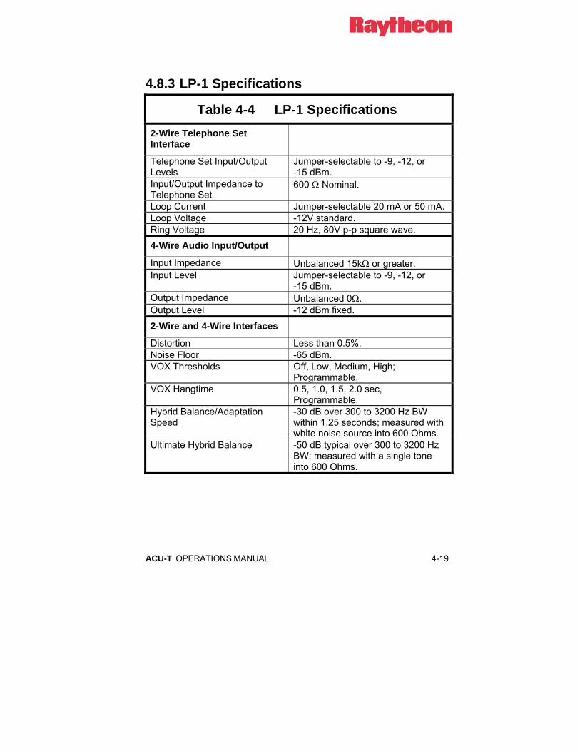
ACU-T OPERATIONS MANUAL 4-19
4.8.3 LP-1 Specifications
Table 4-4 LP-1 Specifications 2-Wire Telephone Set Interface
Telephone Set Input/Output Levels
Jumper-selectable to -9, -12, or -15 dBm.
Input/Output Impedance to Telephone Set
600 Ω Nominal.
Loop Current Jumper-selectable 20 mA or 50 mA. Loop Voltage -12V standard. Ring Voltage 20 Hz, 80V p-p square wave.
4-Wire Audio Input/Output
Input Impedance Unbalanced 15kΩ or greater. Input Level Jumper-selectable to -9, -12, or
-15 dBm. Output Impedance Unbalanced 0Ω. Output Level -12 dBm fixed.
2-Wire and 4-Wire Interfaces
Distortion Less than 0.5%. Noise Floor -65 dBm. VOX Thresholds Off, Low, Medium, High;
Programmable. VOX Hangtime 0.5, 1.0, 1.5, 2.0 sec,
Programmable. Hybrid Balance/Adaptation Speed
-30 dB over 300 to 3200 Hz BW within 1.25 seconds; measured with white noise source into 600 Ohms.
Ultimate Hybrid Balance -50 dB typical over 300 to 3200 Hz BW; measured with a single tone into 600 Ohms.

4-20 ACU-T OPERATIONS MANUAL
Digital Inputs (/AUXI1, /AUXI 2, /PTT)
Standard Polarity Active Low. Threshold 2.5V nominal. Input Impedance 47kΩto +5V. Protection ±100V.
Digital Outputs (/AUXO1, /AUXO2, /VOX)
Standard Polarity Active Low. Type Open Drain, weak pull-up 47kΩ to
+5V. Maximum Voltage +60V. On Resistance 5 Ω nominal. Maximum Current Sink 50 mA.
General
Front Panel Monitor, Ring, Off-hook, VOX, and Fault LEDs.
Rear 60 Pin PC edge connector for backplane.
Input Power +12V, +Bus Voltage supplied by the backplane.
Size 4HP-Wide Eurocard Module: 5’’H x 0.8’’W x 9’’D.
Weight 1.0 lb. (0.5kg).

ACU-T OPERATIONS MANUAL 4-21
4.9 AP-1 Module
4.9.1 AP-1 General Description The AP-1 module is a general-purpose 4-wire module that can provide a variety of DSP operations. Unlike other ACU-T modules, the AP-1 does not communicate with the system audio and control bus structures on the ACU-T backplane. The AP-1 is “In Series” with the audio signal that is routed through it via the associated rear panel connector. The ACU-T chassis merely provides to the AP-1s DC power and a place to reside. The DSP functions of the AP-1 can operate either on the audio and control signal coming into the ACU-T module that it is associated with it (AP-1 RX Option Assembly), or on the audio and control signal that is exiting the associated ACU-T module (AP-1 TX Option Assembly). Alternatively, the AP-1’s DSP features can be used to modify signals not associated at all with the ACU-T. In this case, the customer can manufacture custom cabling to suit the application.
See Table 2-8.

4-22 ACU-T OPERATIONS MANUAL
4.9.2 Block Diagram Description (Refer to Error! Reference source not found.)
The AP-1 contains its own DSP processor that does all of the local control of the AP-1 module. It operates alone and does not communicate with the system’s CPM-2 module over the control and data buses, as do the other ACU-T modules.
The function of the AP-1 module is to connect four-wire input audio to its internal DSP processor and route processed four-wire output audio back to the outside world. The audio processing performed by the AP-1 depends on the software installed in the module. Different versions of software are available that perform a variety of specific applications. Since this software may vary from unit to unit it will not be described here.
Input audio is routed through amplifier U11A then through amplifier U11B, which is gain-controlled by potentiometer R21, and then into the DSP module A/D input. The DSP module processes the audio and outputs its signal from the D/A through amplifier U12A, U10A then through amplifier U10B, where the output level is set by pot R3.
The /AuxO1, /AuxO2, and /PTT digital outputs are generated by transistors Q1, Q2 and Q4 which are driven by the DSP module. Digital inputs /AuxI1, /AuxI2, and COR, are routed to gates U24A, U24B, and U24D, which are read by the DSP module. Transistor Q3 switches the COR input to accommodate either and active-low or active-high input signal. An RS-232 interface chip, U25, changes RS-232 voltage levels into TTL voltage levels for processing by the DSP module. This is functional only when the AP-1 contains software that utilizes RS-232 processing.

ACU-T OPERATIONS MANUAL 4-23
4.9.3 AP-1 Specifications
Table 4-5 AP-1 Specifications RX Audio Input
Input Impedance Balanced /Unbalanced 600 Ω; Unbalanced 47kΩ.
Input Level -20 to +12 dBm, adjustable. Frequency Response 100 Hz to 3200 Hz ± 2 dB.
TX Audio Output
Output Impedance Balanced or Unbalanced 600Ω. Output Level -26 to +5 dBm, adjustable. Frequency Response 100 Hz to 3200 Hz ±2dB. Distortion Less than 0.5%. Noise Floor -60 dBm.
Digital Inputs
Standard Polarity Active Low. Threshold 2.5V nominal. Input Impedance 47kΩ to +5V. Protection ±100V.
Digital Outputs
Standard Polarity Active Low. Type Open Drain, with weak pull-up 47kΩ to
+5V. Maximum Voltage +60V. On Resistance 5 Ω nominal. Maximum Current Sink 50 mA.
General
Front Panel Bypass Switch & LED; PTT, Normal and Peak LEDs.
Rear 60 Pin PC edge connector for backplane. Input Power +12V; +Bus voltage supplied by the
backplane. Size 5’’H x 0.8’’W x 9’’D. Weight 1lb. (0.5kg).

4-24 ACU-T OPERATIONS MANUAL
The following pages give these block diagrams:
Figure 4-1 HSP-4 Block Diagram
Figure 4-2 DSP-1 Block Diagram
Figure 4-3 PSTN-1 Block Diagram
Figure 4-4 LP-1 Block Diagram
Figure 4-5 AP-1 Block Diagram

ACU-T OPERATIONS MANUAL 4-25
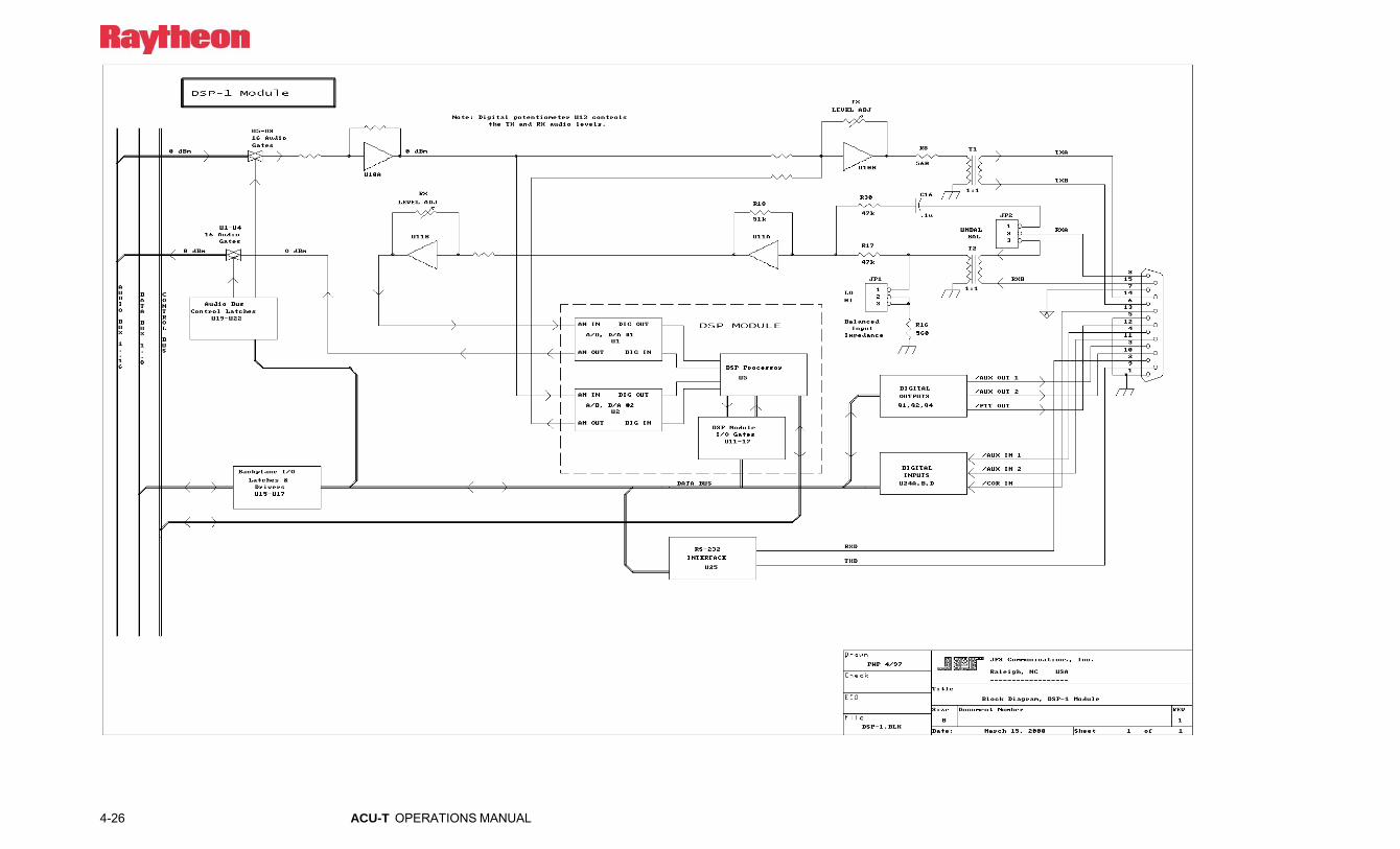
4-26 ACU-T OPERATIONS MANUAL

ACU-T OPERATIONS MANUAL 4-27
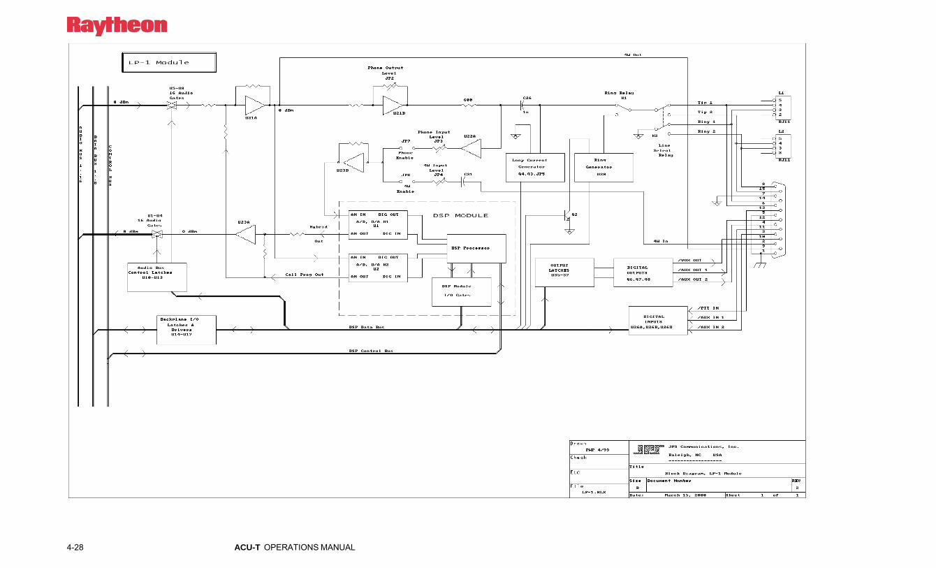
4-28 ACU-T OPERATIONS MANUAL

ACU-T OPERATIONS MANUAL 4-29 - 4-29 -


ACU-T OPERATIONS MANUAL 5-1
5 Options This section explains some of the optional equipment that is available for use with the ACU-T. This document provides all instructions necessary to interface and operate a STU-III encrypted phone with the ACU-T.
5.1 STU-III Option
5.1.1 Equipment Required
Table 5-1 Required Equipment
Equipment Part Number Qty.
ACU-T 5951-800000 (1) ACU-T STU-III Option 5030-206000 (1)
Note that the ACU-T must have a spare DSP-1 module for the STU-III option to interface with.
5.1.2 Application The option allows a STU-III user to access any ACU-T radio net. The figure below shows a STU-III call cross-connected to an encrypted radio. The STU-III can also be cross-connected into a standard radio or standard PSTN line, or any other device that can be interfaced to the ACU-T system. The audio within the ACU-T is clear, decrypted audio.

5-2 ACU-T OPERATIONS MANUAL
Example of Encrypted Cross-Connection-STU-III Phone to Encrypted Radio-
Using Raytheon JPS STU-III Interface in conjunction with the
ACU-T Intelligent Interconnect.
STU-III Phone
PSTNRJ-11
HSP-4Handset/Speaker
CPM-2Control
Processor
DSP-1Radio
Interface
DSP-1Radio
Interface
DSP-1Radio
Interface
ACU-T
E
DRadio
STU-IIIInterface
Box
STU-III Phone
RJ-11 E = EncryptD = Decrypt
RS-232STU-III
Handset
RJ-9
RJ-45 ConnectEnable
RCV
XMT
DB-15RJ-45
RJ-9
12 VDC
KY-57
To ACU-T DC Inputon Rear Panel
PC WithACU Controller
Software
ACU-THandset
Figure 5-1 STU-3 Basic System
5.1.3 Installation Note: STU-3 Option Must Interface with a DSP-1
Module, not a PSTN-1 Module.
5.1.3.1 Connecting the STU-III phone to the ACU-T 1.) Plug the STU-III phone into the telephone jack in the wall.
2.) Remove the handset cord from the STU-III phone.
3.) Find the supplied telephone cables with an RJ-9 connector on one end and RJ-11 on the other.
Note: The RJ-9 is the connector used with the handset, the RJ-11 is the connector used with the STU-III interface boxes.

ACU-T OPERATIONS MANUAL 5-3
4.) Plug in the supplied cables between the STU-III interface box and the STU-III phone.
a.) Plug in one of the RJ-11s into the “HAND-SET” jack located on the STU-III interface box, plug the other end of the cable (RJ-9) into the handset of the STU-III phone.
b.) Plug in the other RJ-11 into the “PHONE” jack located on the STU-III interface box, plug the other end of the cable (RJ-9) into the base of the STU-III phone where the hand-set cable would normally be connected.
5.) Find the supplied ACU/STU-III cable with a DB-15 connector terminating each end of the cable.
a.) Plug the end of the cable identified STU-III END into the “INPUT” connector on the STU-III interface box. This DB-15 will have a cable and two separate conductors terminated within the shell. The two conductors (one red and one black) are used to power the STU-III boxes. Connect the other end of the red and black conductors to the back of the ACU-T DC-INPUT battery terminals (using the Molex connector). When using the ACU-T with a STU-III interface, the ACU-T rear panel Charge Switch must be in the “Charge” position. The charge voltage powers the STU-III option.
b.) Located on the side panel of the ACU-T are CPC receptacles, which correspond to the modules mounted in the front of the chassis. Receptacle J1 on the ACU-T is used for extension 01, which is the first module after the CPM-2. The same principle is true for the remaining 4 extensions. Plug in the other end of the cable coming from the STU-III box into the extension (J1-J5) the user wants to use with the STU-III phone. If the cable is plugged into J1 on the ACU-T, then the STU-III phone will work with the DSP-1 module in extension 01.
5-4 ACU-T OPERATIONS MANUAL
5.1.3.2 ACU-T Alignment for STU-III 1) Make a call from the local STU-III telephone; establish a voice
link with the party on the distant STU-III phone. Place the STU-III phones into the secure mode and pause for the phone to report that it is in the secure mode. For this example, it will be assumed the STU-III phone is connected to J1, associated with the DSP-1 at extension 01. Connect the standard ACU-T handset to the HSP-4 module. Cross-connect the HSP-4 module to the DSP-1 connected to the STU-III phone, in this example it would be extension 01. This connection can be made via the ACU-T Console Interface program or via the HSP-4 keypad. When the HSP-4 is connected to the DSP-1 associated with the STU-III phone, the STU-III handset will no longer work, and the ACU-T’s handset will now be the functional handset for the conversation. The user can now talk to the party on the distant phone via the handset plugged into the HSP-4 module. The user must push the PTT button on the handset to send audio to the distant user.
Note: If no audio is heard from the distant listener it may be necessary to move the STU-III Interface Option polarity switch to the opposite position. Some manufacturers such as Motorola use the opposite MIC polarity as related to ATT and others.
2) The user may now set up the DSP-1 levels to match the STU-III phone. The TX and RX levels of the DSP-1 modules may be adjusted via either the ACU Controller Software program or the HSP-4 module.
The user should talk to the party at the distant phone and find out how the audio level sounds are at the distant end. If the level needs to be adjusted, the local user should adjust the DSP-1 TX level. If the local user finds the levels coming from the distant phone are too loud or too quiet the user should adjust the RX level of the DSP-1 module. Once the levels are set, they should not need to be adjusted again unless the phone changes.

ACU-T OPERATIONS MANUAL 5-5
Note: The volume knob on the STU-III phone also controls the output to the ACU-1000.
3) The COR type for the DSP-1 module should be in VOX mode for use with a STU-III phone. VOX mode is the factory default.
5.1.4 Operation: Cross Connecting a STU-III phone
Once the STU-III has gone secure the user may cross connect it to another STU-III phone, a local phone, radio, sound card in computer, or any other audio device that is also interfaced to the ACU-T following standard cross-connection procedures.

5-6 ACU-T OPERATIONS MANUAL
Blank Page

ACU-T OPERATIONS MANUAL 6-1
6 Index
A
ACU-T Card Cage.............................. 1-1 General .................................. 1-1 General Information .............. 1-1 Power Supply ........................ 1-2
ACU-T Operation.................... 3-25 ACU-T Technical Information.. 4-1 Antenna Location and Desensing 2-
4 Antenna Options........................ 2-6 AP-1
4-33 Block Diagram Description. 4-22 Cable Information ............... 2-22 Control Tone Detection....... 2-32 Control Tone Generation..... 2-32 Digital Delay ....................... 2-30 2-30 Digital SW-4 ....................... 2-30 DSP Function Enable, SW4 2-32 Function Enable Switches, SW4
......................................... 2-31 4-21 General Information ............ 2-29 Installation Notes ................ 2-33 2-24 Module ................................ 2-21 Options .................................. 1-6 RX Option ........................... 2-31 Specifications ...................... 4-23 SW3..................................... 2-30 2-32 2-30
2-29 2-31
4-33 1-6, 4-21 2-21 Attention Command
HSP-4 Operational Command Items ................................. 3-7
HSP-4.................................... 3-9 Interface Module Operational
Commands ............. 3-17, 3-19
B
Basic Chassis Modules - Functions and Operation........................ 3-5
Battery Power for the ACU-T. 2-13 Break a Connection
HSP-4.................................... 3-9 Interface Module Operational
Commands ...................... 3-18 Break the Current Connections
HSP-4 Operational Command Items ................................. 3-7
Interface Module Operational Commands ...................... 3-17
Bypass Mode........................... 2-29
C
Charge Switch......................... 2-13 Chassis Slots, Extensions,
Connectors, and Modules.... 2-17 Configuration Programming Items
............................................ 2-38 Connect LED (PSTN-1)............ 3-4 Cooling ..................................... 2-8
6-2 ACU-T OPERATIONS MANUAL
COR LED (RDI-1, DSP-1) .......3-4 CPM-2
Baud Rate ............................2-26 Functions and Operation .......3-5 Manufacturing Test SW1-8 .2-28 Remote Control Enable .......2-27 Serial Sync Character ..........2-27 Store Configuration SW2-1.2-28 SW1-5, 6, 7..........................2-28 SW2-1 through SW2-8........2-28 Switch Settings....................2-26
CPM-2 Module..........................1-4
D
Data / Command Modes HSP-4 ..................................3-11 Interface Module Operational
Commands.......................3-19 Data /Command Mode
Interface Module Operational Commands.......................3-17
Data/Command Mode HSP-4 Operational Command
Items..................................3-7 Delete PIN Numbers from the
Database ..............................3-24 Desensing ..................................2-4 Desensing Effects ......................2-5 Discone......................................2-7 Disconnect Another Extension
HSP-4 Operational Command Items..................................3-7
HSP-4 ....................................3-9 DSP-1
Block Diagram Description...4-8 Block Diagram ....................4-27 Functions and Operation .....3-15
DSP-1 and RDI-1 Programming Audio Muted When Squelched2-
65 Auxiliary Output Control ....2-69 COR Inhibit Time After PTT ..2-
66
COR Polarity....................... 2-53 COR Sampling .................... 2-62 COR Type, VOX/VMR
Threshold, Hangtime, and Audio Delay .................... 2-56
DTMF Command Enable.... 2-67 DTMF Mute Timer ............. 2-54 DTMF Pre-emphasis ........... 2-68 Full/Half Duplex ................. 2-54 High Frequency Equalizer... 2-68 Module Security Level Selection
........................................ 2-67 Noise Reduction Value ....... 2-64 PTT or COR Priority........... 2-66 Receive Level...................... 2-52 Transmit Keying Tones/Keying
Tone Amplitude .............. 2-65 Transmit Level .................... 2-53 Voice Prompt Initiation Delay 2-
69 2-52 DSP-1 Module .......................... 1-4 DSP-1 Module Connections.... 2-18 DSP-1 Programming Items ..... 2-39 DSP-1 Specifications .............. 4-10 Dual-Band Whip ....................... 2-7 dual-band whip antennas........... 2-6
E
Equipment and Accessories Supplied ................................ 1-9
Extension Cables....................... 2-5 External Interconnect Information
............................................ 2-16
F
Fault LEDs (HSP-4, DSP-1, PSTN-1, LP-1) ................................. 3-3
Front And Top Panel Controls and Indicators............................... 3-1

ACU-T OPERATIONS MANUAL 6-3
G
General Operation............................... 3-1
Glossary ..................................... xii COR ....................................... xii COS........................................ xii CPM-2.................................... xii CTCSS ................................... xii DTMF..................................... xii Extension................................ xii Hangtime................................ xii HSP-4..................................... xii LP-1....................................... xiii Slot ........................................ xiii SNR....................................... xiii Squelch.................................. xiii VMR ..................................... xiii VOX...................................... xiii
H
Hardware Configuration Settings 2-23, 2-24
Headphones Output Jack (HSP-4)............................................... 3-2
How Desensing Affects the TRP-1000....................................... 2-5
HOW TO USE THE PIN SECURITY FEATURE ...... 3-24
HSP-4 Block Diagram .................... 4-25
HSP-4 Block Diagram Description... 4-4 Functions and Operation ....... 3-6 General Description .............. 4-3
HSP-4 Module........................... 1-3 HSP-4 Module Connections.... 2-17 HSP-4 Operational Command
Items...................................... 3-7 HSP-4 Specifications ................ 4-6 HSP-4 Squelch Type ............... 2-51 HSP-4 Programming Items ..... 2-51
I
Index ......................................... 6-1 Installation ................................ 2-1 Installation Checklist .............. 2-15 Installation Considerations........ 2-3 Installation Overview................ 2-3 Interface Module Operational
Commands .......................... 3-17 Interface Modules ................... 1-10 Interface Modules – Functions and
Operation ............................ 3-14
J
J0 3-12
L
List of Figures...............................x List of Tables ...............................xi Log Periodic.............................. 2-7 LP-1
Block Diagram........... 4-31, 4-33 Block Diagram Description 4-17 Functions and Operation ..... 3-16 General Description ............ 4-17 Jumper Settings................... 2-34 Specifications...................... 4-19
LP-1 Module ............................. 1-5 LP-1 Module Connections ...... 2-20 LP-1 Programming Items... 2-47, 2-
77 Audio Delay........................ 2-79 Aux Output Control ............ 2-81 Dial and Busy Tone Style ... 2-80 Dial Tone Enable ................ 2-80 DTMF Command Enable.... 2-81 DTMF Mute Timer ............. 2-77 Module Security Level Selection
........................................ 2-79 Ring Cadence...................... 2-80 Ringback Enable ................. 2-80 Ringing Time ...................... 2-81

6-4 ACU-T OPERATIONS MANUAL
Voice Prompt Initiation Delay.2-82
VOX Hang Time .................2-79 VOX Threshold ...................2-79
M
Make a Connection HSP-4 ....................................3-8 Interface Module Operational
Commands.......................3-18 Make A Connection
HSP-4 Operational Command Items..................................3-7
Interface Module Operational Commands.......................3-17
Master/Slave LEDs (CPM-2) ....3-3 Mon (Monitor) LED (DSP-1,
PSTN-1, LP-1) ......................3-3 Monitor Function
HSP-4 Operational Command Items..................................3-7
HSP-4 ..................................3-10 Interface Module Operational
Commands..............3-17, 3-19
O
Off Hook LED (LP-1) ...............3-4 Operation
Conference Call...................3-33 Local Phone to Radio ..........3-32 Radio to Local Operator ......3-29 Radio to PSTN ....................3-31
Operation...................................3-1 Basic Operation Scenarios...3-26 Local Operator to Radio ......3-29 PSTN to Radio ....................3-28 Radio to Radio.....................3-27 Unit Power-Up ....................3-25
Optional Equipment - Not Supplied.............................................1-11
P
2-24 Pictorial Layout for Operating
Scenarios ............................. 3-26 Pin Security
Exclusive Operation Mode.. 3-22 How PIN Security Works.... 3-21 3-22 How to Set........................... 3-23 Input PIN Numbers into the
ACU-T Database............. 3-23 Priority Operation Mode ..... 3-22 The Two Different PIN Security
Modes.............................. 3-22 PIN Security............................ 3-21
How to Delete PIN Numbers from the Database ........... 3-24
PIN SECURITY FEATURE... 3-24 Power Requirements ............... 2-12 Programming Configuration
Settings................................ 2-35 Proper Setup of System Antennas2-
4 Proper Use of Extension Cables 2-5 Proper Use of Ground Planes.... 2-6 PSTN-1
Block Diagram .................... 4-29 Block Diagram Description. 4-12 Functions and Operation ..... 3-15 General Description ............ 4-12
PSTN-1 Module ........................ 1-4 Technical Information......... 4-12
PSTN-1 Module Connections . 2-19 PSTN-1 Programming Items.. 2-45,
2-70 2-Wire/4-Wire Operation .... 2-73 Audio Delay ........................ 2-72 Auxiliary Output Control .... 2-74 Dial Mode ........................... 2-71 DTMF Command Enable.... 2-74 DTMF Mute Timer ............. 2-71 Inactivity Disconnect Timer 2-75
ACU-T OPERATIONS MANUAL 6-5
Module Security Level Selection......................................... 2-73
PSTN Type.......................... 2-70 Ringing Time ...................... 2-74 Telephone Line Level.......... 2-70 Telephone Receive Level Boost
......................................... 2-70 Voice Prompt Initiation Delay 2-
75 VOX Hang Time ................. 2-73 VOX Threshold................... 2-72
PSTN-1 Specifications ............ 4-15 PTT LED (DSP-1), VOX LED
(PSTN-1, LP-1) ..................... 3-3
R
Rear Panel Connectors .............. 3-5 Regain Control
HSP-4 Operational Command Items.................................. 3-7
Regain Control from Console Program HSP-4.................................. 3-11
Removal and Replacement of Modules............................... 3-35
Report Connections HSP-4 Operational Command
Items.................................. 3-7 HSP-4.................................... 3-9
Reshipment of Equipment......... 2-2 Ring LED (PSTN-1, LP-1)........ 3-4
S
Serial Remote Connector2-22, 2-24 Serial Remote Control (RS-232) . 3-
35 Setup of System Antennas......... 2-4 Signal LED (DSP-1) ................. 3-3 Speaker Switch (Top panel) ...... 3-2 Specifications ............................ 1-8 Store Connection Table in Memory
HSP-4.................................. 3-10 Store Connections
HSP-4 Operational Command Items ................................. 3-7
STU-3 Alignment ............................. 5-4 Applications .......................... 5-1 Basic System......................... 5-2 Cross Connecting.................. 5-5 Equipment Required ............. 5-1 Installation ............................ 5-2
System Antennas....................... 2-4 System Programming
Console Override ................ 2-49 Delete Pin's ......................... 2-51 Enter Programming Mode... 2-49 Exit Programming Mode..... 2-50 Module Security Level Selection
........................................ 2-51 Pin Numbers ....................... 2-50 Program Pins....................... 2-51 Reset Modules to Factory
Settings............................ 2-50 Select a Module to Program 2-50
System Programming and Operating Items................... 2-49
System Programming Item ..... 2-38 System Reset
HSP-4 Operational Command Items ................................. 3-7
Interface Module Operational Commands ...................... 3-17
System Reset Feature HSP-4.................................. 3-12 Interface Module Operational
Commands ...................... 3-20 System Software ....................... 1-5
T
Table of Contents........................ iii Technical Information
Card Cage and Backplane..... 4-1 CPM-2 Control Processor
Module:............................. 4-2 DSP-1 Module ...................... 4-8
6-6 ACU-T OPERATIONS MANUAL
General Description...............4-1 HSP-4 Handset/Speaker Module
...........................................4-3 HSP-4 Specifications.............4-6 LP-1 Module .......................4-17
Tuned Whip...............................2-7
U
Unpacking and Inspection .........2-1 Use of Radio at HSP Connector J0
.............................................3-12
V
Volume Control (Top Panel)..... 3-3
W
Warranty ...................................... ii
Y
Yagi........................................... 2-7

ACU-T OPERATIONS MANUAL 6-7
This Page Intentionally Left Blank