Embed Size (px)
Citation preview

HUBBELL
Tachometer SignalLoss Assembly
4922c Instruction ManualPublication 189 TLA
March 1995
JPS-395-0M © 1995Printed in U.S.A.
HubbellIndustrial
Controls, Inc.a subsidiary of Hubbell Inc.4301 Cheyenne DriveArchdale, NC 27282
(336) 434-2800Fax (336) 434-2803

HUBBELLGeneral Description 30
Tach Signal Loss Assy.
49232-101 Tachometer Signal Loss Assembly
GeneralDescriptionThe 49232-101 & -102Tachometer Signal Loss As-sembly monitors a speedregulated system’s DC ta-chometer signal and com-pares this signal with thesystem’s commandingspeed reference. A speeddifference error signal isproduced and comparedto an adjustable differentialwindow. If the speed differ-ence signal falls outsidethe differential window forlonger than an adjustabletime limit, the unit’s LowVoltage relay willdeenergize. The Low Volt-age relay will deenergizeimmediately if the absolutevalue of the monitored ta-chometer signal exceeds125% of the selected syn-chronous speed, thus pro-viding a fixed overspeedsensing function.
The Tachometer SignalLoss Assembly can monitor50V or 100VDC tachom-eters, can be set for stan-dard 60 hz synchronousmotor speeds from 600–1800 rpm, can be set toaccept bipolar or positiveonly speed reference sig-nals of up to 50V in mag-nitude, and provides ad-justments for DifferentialError, Error Time, andSpeed Reference SignalAttenuation.
There are two signal levelLockout Command inputsand one 120VAC controlcircuit Isolated LockoutCommand input. These in-puts are used to overridethe unit’s comparison func-tion during periods ofnonspeed regulated op-eration such as Full Speedregenerative lowering ortorque/current limiting re-
versing plugging. Thelockout inputs do not dis-able the overspeed sens-ing function.
ApplicationInformationThe 49232-101 & -102Tachometer Signal Loss As-sembly can be used tomonitor and verify thespeed feedback signal ofspeed regulated controlsystems. The -101 assem-bly will monitor 50V ta-chometers and the -102assembly will monitor100V tachometers. Theassemblies can be set forany of five standard60 hz synchronous ta-chometer speed ranges,and to accept either bipo-lar, ±Ref, or positive only,+Ref, system speed refer-ence signals. The assem-blies also provide immedi-ate detection of overspeedconditions. This functionwill respond to tachometersignal levels exceeding125% of the selectedspeed range.
The assemblies have threeadjustment potentiometers:
1. The Reference Attenu-ation potentiometerallows the systemspeed reference sig-nal to be adjustedand scaled to matchthe speed feedbacksignal requirements.
2. The Differential Poten-tiometer sets thespeed reference errorwindow and deter-mines how precisethe speed must followthe system reference.
3. The Time Potentiom-eter sets the time pe-riod that a sensedspeed tracking error
must exist before theoutput LV relay isdeenergized. Thetime delay function isbypassed when anoverspeed conditionis sensed, causingthe LV relay to disen-gage immediately.
The assemblies have twosignal level Lockout inputs,and one control circuit Iso-lated Lockout input. Theseinputs can be used to in-hibit the speed trackingfunction. When any ofthese inputs are activated,the output LV relay will re-main energized regardless
Section Contents
General Description .. 2
Application Info. ....... 2
Specifications .......... 3
Adjusting TSLA ......... 5
Troubleshooting ........ 6
Tachometer Signal Loss Assembly
0 100
50
0 100
50
0 100
50
P1
JP1
JP2
P2
P31
REFTP4 TP5 TP6
TP1 TP2 TP3
±TACH –|TACH|
±ERROR –|ERROR| 0 V
TB3
RPM SELECT
TB2
+TACH
–TACH
LOCKOUT #1
LOCKOUT #2
REFERENCE
+SUPPLY
–SUPPLY
TACH LOSS OUT
0 VOLT
DIFF
REFATTN
LED2
LED1
12 11 10 9
RELAY
TIME
+ REF ±
TB1
1 2 3 4
600
720
900
1200
1800
4922c Instruction ManualPublication 189 TLA
March 1995

HUBBELL
of the speed to referenceerror. Overspeed detectionis not inhibited by the acti-vation of any of the lock-out inputs.
The assemblies have aTach Loss Output signal.This current sinking outputcan be connected to 0Vreferenced circuits andused to confirm to thespeed controlling systemthat the motor and tachom-eter are tracking the sys-tem speed reference sig-nal within the set differen-tial limits. This output canalso be used to control anexternal relay. Note: afree-wheeling diode mustbe placed in parallel withthe coil of the external re-lay. This output can sink200 mA to 0V at 70°C.
Figures T2 (on the nextpage) shows a typicalhoist control application ofthe Tachometer Signal LossAssembly. The LV relay onthe assembly is used asthe system low voltage re-lay. The 120V control volt-age is connected to TB1-1,2 and to TB1-3,4. AnyLV circuit permissive con-tacts such as overload orthermostat contacts areconnected in series be-tween TB1-5,6 and TB1-7,8. For standard Off-Point reset operation, theOff-Point setup circuitneeds to be in place.
This is done by jumperingTB2-5,6 and TB2-3,4,and connecting the Off-Point initiating contacts be-tween TB1-1,2 and TB2-5,6. This completes the120V control circuit con-nections for the LV relay.
The motor control systemthat the Tachometer SignalLoss Assembly is monitor-ing, supplies the regulatedDC power for the unit’selectronics. The 0V con-nection is made to TB3-1.The +8.0 to +12.0VDCpower is connected to
TB3-4, and the –8.0 to–12.0V power is con-nected to TB3-3.
The Tachometer Loss out-put, TB3-2, can be con-nected to the TachometerContinuity input on theSpeed Regulating system.This signal provides a di-rect input to the SpeedRegulating system’s Permis-sive circuit. Should this con-nection not be desired, theTach Loss output can be leftopen, but the tachometercontinuity input on thespeed regulating controlshould be jumpered to 0Vto enable the permissivecircuit. The latter is the typi-cal connection.
The speed regulatingcontrol’s Ramp signal isused as the comparisonreference for the moni-tored tachometer signal.The Ramp signal from thespeed control is con-nected to TB3-5.
The system tachometer isconnected to TB3-8 and
Application Information 31
Tachometer Signal Loss Assembly
SpecificationsInput Power and Signals
LV Control Circuit ............... 120V AC
Signal Circuit Power Supply . 30 mA. loading;±8.0VDC to±12.0VDC
Tachometer Signal
–101 assembly ................. 50V/1000 rpm
–102 assembly. ................ 100V/1000 rpm
System Speed Reference ..... up to 50VDC
Lockouts #1 and #2 ........... connect to + Supply10K ohm load to 0V
Isolated Lockout ................. 10 mA loading @120VAC
OutputTach Loss Out ................... 200 mA sink to 0V
from +Supply @ 70°C
LV Relay ........................... 2 – N.O. @ 10 amps,120VAC @ 70°C
AdjustmentsRPM Select (rpm) (JP1) ......... 600, 720, 900,
1200, 1800
Reference Select (JP2) ......... ±Ref, +Ref
Reference Atten (P1) ........... input reference signalscaling
Differential (P2) .................. 5% – 100%
Time Delay (P3) ................. 0.25–5.0 seconds
Indicators / DiagnosticsLED1............................... Isolated Lockout active
LED2............................... LV Relay engaged
Test Point 1 (TP1) ............... Scaled speed ref.±5.0V System SyncSpeed
Test Point 2 (TP2) ............... Scaled ±Tach; ±5.0Vfor System SyncSpeed; ±6.25V forOverspeed level
Test Point 3 (TP3) ............... –|Tach|; –5.0V for Sys-tem Sync Speed;–6.25V for Overspeedlevel
Test Point 4 (TP4) ............... ±Error; ±5.0V for trip@ set differential
Test Point 5 (TP5) ............... –|Error|; –5.0V for trip@ set differential
Test Point 6 (TP6) ............... 0V
Temperature Range ............ –4°F (–20°C) to158°F (70°C)
TB3-9. The polarity of thetachometer signal is impor-tant when the speed con-trol Ramp signal is bipolar.For typical applications,the positive tachometerline is connected to TB3-9for the Raise or Hoist mo-tion when a positivespeed reference Ramp sig-nal is present at TB3-5.
The Isolated Lockout inputis used to disable thespeed tracking function ofthe Tachometer Signal LossAssembly. The trackingfunction should be dis-abled at any time that thespeed control system is notactively providing speedcontrol operation, such asfull speed, full voltageRaise or Hoist, full voltageregenerative lower, or pro-longed current limit opera-tion during a stalled floatsequence. The IsolatedLockout is activated bysupplying 120VAC fromTB2-1,2 to TB1-3, 4
Figure T1 – Outline drawing of TSLA
0 100
50
0 100
50
0 100
50
P1
JP1
JP2
P2
P31
REFTP4 TP5 TP6
TP1 TP2 TP3
±TACH –|TACH|
±ERROR –|ERROR| 0 V
TB3
RPM SELECT
TB2
+TACH
–TACH
LOCKOUT #1
LOCKOUT #2
REFERENCE
+SUPPLY
–SUPPLY
TACH LOSS OUT
0 VOLT
DIFF
REFATTN
LED2
LED1
12 11 10 9
RELAY
TIME
+ REF ±
TB1
1 2 3 4
600
720
900
1200
1800
5.00" typ.
4.50" typ. 0.25"typ.
2.84
"
0.75
"

HUBBELLApplication Information 32
Tachometer Signal Loss Assembly
Figure T2 – a typical TSLA in-stallation for a hoist controller
LV
SCRA SCRB SCRC
To SCR Gate Circuits
XFMR2 Main Firing BoardStatic Control Assy.P/N 49229-XXX
Aux. Firing BoardStatic Control Assy.P/N 49229-XXX
Regulator BoardStatic Control Assy.P/N 49229-XXX
XFMR1
TSLA
SCRD SCRE
MJ2
CCB
2CFU
1OLT
TB3–8
TB2–11 +Tach
TB2–9 Tach Cont.TB2–14 0V
TB2–10 –TachTB2–7 Ramp Out
TB1–1 Permis. Com.
TB1–2 Permissive
TB1–3
Lower LS*
HSR
FS
FS
LR
ToXFMR3
LR
LowerHoist Off
+ –
LR
LSR
LR
BR
BR
HR
HR
TR
HR
HR
MT
Hoist LS*
Full Speed
TB2–
1Re
f.
TB2–
5–8
.5V
TB2–
6+8
.5V
TB3–9
TB3–14–18V
LSR
HSR
LVLV
2OL 3OL
OS
+Tach
MJ3 MJ4 AJ2 AJ4TB1-6TB1-7TB1-3TB1-5TB1-1TB1-2TB1-4
Yellow
Black
Red/Wht
Gray
White/Blue
Blue
Green
White
Red
Brown
Orange
Tach polarity shownis for Hoist/Rev
**Set RPM Select forTachometer Synchronous Speed
Pick up at 20%speed drop outat 10% speed.
Pick up at 70%speed drop outat 60% speed.
* Jumper if not used.
C1
987654321
+Tach
–Tach
Speed Ref
+8.5V
–8.5V
0V
7 8 3 41 2 5 6
5 6 3 4 1 2 7 8
TB3TB1TB1
RPM Select
TB2 TB2
IsolationLockout
60072090012001800
+ REF ±
**
HUBBELL
0 100
50
0 100
50
0 100
50
P1
JP1
JP2
P2
P31
REFTP4 TP5 TP6
TP1 TP2 TP3
±TACH –|TACH|
±ERROR –|ERROR| 0 V
TB3
RPM SELECT
TB2
+TACH
–TACH
LOCKOUT #1
LOCKOUT #2
REFERENCE
+SUPPLY
–SUPPLY
TACH LOSS OUT
0 VOLT
DIFF
REFATTN
LED2
LED1
12 11 10 9
RELAY
TIME
+ REF ±
TB1
1 2 3 4
600
720
900
1200
1800
Adjusting TSLA
Adjusting TSLA 33
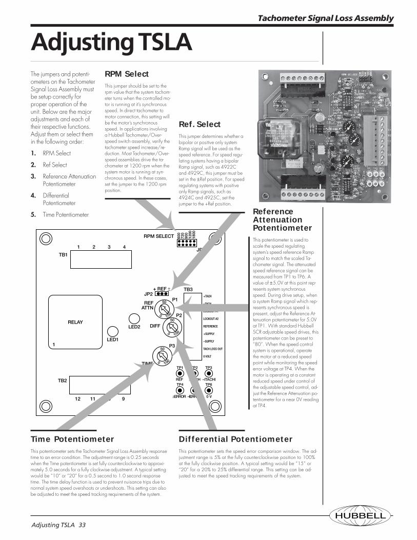
The jumpers and potenti-ometers on the TachometerSignal Loss Assembly mustbe setup correctly forproper operation of theunit. Below are the majoradjustments and each oftheir respective functions.Adjust them or select themin the following order:
1. RPM Select
2. Ref Select
3. Reference AttenuationPotentiometer
4. DifferentialPotentiometer
5. Time Potentiometer
Tachometer Signal Loss Assembly
Differential PotentiometerThis potentiometer sets the speed error comparison window. The ad-justment range is 5% at the fully counterclockwise position to 100%at the fully clockwise position. A typical setting would be “15” or“20” for a 20% to 25% differential range. This setting can be ad-justed to meet the speed tracking requirements of the system.
Time PotentiometerThis potentiometer sets the Tachometer Signal Loss Assembly responsetime to an error condition. The adjustment range is 0.25 secondswhen the Time potentiometer is set fully counterclockwise to approxi-mately 5.0 seconds for a fully clockwise adjustment. A typical settingwould be “10” or “20” for a 0.5 second to 1.0 second responsetime. The time delay function is used to prevent nuisance trips due tonormal system speed overshoots or undershoots. This setting can alsobe adjusted to meet the speed tracking requirements of the system.
ReferenceAttenuationPotentiometerThis potentiometer is used toscale the speed regulatingsystem’s speed reference Rampsignal to match the scaled Ta-chometer signal. The attenuatedspeed reference signal can bemeasured from TP1 to TP6. Avalue of ±5.0V at this point rep-resents system synchronousspeed. During drive setup, whena system Ramp signal which rep-resents synchronous speed ispresent, adjust the Reference At-tenuation potentiometer for 5.0Vat TP1. With standard HubbellSCR adjustable speed drives, thispotentiometer can be preset to“80”. When the speed controlsystem is operational, operatethe motor at a reduced speedpoint while monitoring the speederror voltage at TP4. When themotor is operating at a constantreduced speed under control ofthe adjustable speed control, ad-just the Reference Attenuation po-tentiometer for a near 0V readingat TP4.
Ref. SelectThis jumper determines whether abipolar or positive only systemRamp signal will be used as thespeed reference. For speed regu-lating systems having a bipolarRamp signal, such as 4922Cand 4929C, this jumper must beset in the ±Ref position. For speedregulating systems with positiveonly Ramp signals, such as4924C and 4925C, set thejumper to the +Ref position.
RPM SelectThis jumper should be set to therpm value that the system tachom-eter turns when the controlled mo-tor is running at it’s synchronousspeed. In direct tachometer tomotor connection, this setting willbe the motor’s synchronousspeed. In applications involvinga Hubbell Tachometer/Over-speed switch assembly, verify thetachometer speed increase/re-duction. Most Tachometer/Over-speed assemblies drive the ta-chometer at 1200 rpm when thesystem motor is running at syn-chronous speed. In these cases,set the jumper to the 1200 rpmposition.
HUBBELLTroubleshooting. 34
Tachometer Signal Loss Assembly
TroubleshootingThe function of the Ta-chometer Signal Loss As-sembly is to compare thespeed regulated system’stachometer speed feed-back signal to the systemspeed reference signal.In normal speed regu-lated operation, thesetwo signals should trackdue to the controlling ac-tion of the speed regula-tor. If a problem shoulddevelop with the tachom-eter feed back system,such as a broken orloose coupling, brokendrive belt, or open ta-chometer signal circuit,the Tachometer SignalLoss Assembly willdeenergize the LV relayon the assembly. A prob-lem with the speed regu-lating control system thatwould cause the systemspeed not to track thespeed reference signalwill also cause the unit todeenergize the LV relay.
Verify theSetupVerify the setup of the Ta-chometer Signal Loss As-sembly by following thesetup procedure outlinedin the Adjusting Tachom-eter Signal Loss Assemblysection.
Unit PowerFor proper operation ofthe unit, 120VAC mustbe present. This is indi-cated by having
1. 120VAC at terminalsTB1-1,2 to TB1-3,4
2. DC control power inthe range of +8.0 to+12.0V must bepresent at TB3-4 toTB3-1, and –8.0 to–12.0V must bepresent at TB3-3 toTB 3-1.
LV RelayDoesn’tEnergizeIn order for the LV relay topickup, the unit must bepowered as describedabove, the Off-Point resetcircuit must be in place,and the overload/thermo-stat circuit must be com-plete. The Off-Point resetcircuit connects TB1-1,2to TB2-5,6. TB2-5,6 mustbe jumpered to TB2-3,4for proper Off-Point resetoperation. The overload/thermostat circuit connectsTB1-5,6 to TB1-7,8.Verify the operation andfunction of these control-ling circuits.
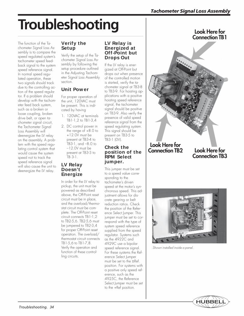
LV Relay isEnergized atOff-Point butDrops OutIf the LV relay is ener-gized at Off-Point butdrops out when presenceof the controlled motionis started, verify the ta-chometer signal at TB3-8to TB3-9. For hoisting ap-plications with a positivehoisting speed referencesignal, the tachometersignal should be positiveon TB3-9. Also verify thepresence of valid speedreference signal from thespeed regulating system.This signal should bepresent on TB3-5 toTB3-1 (0V).
Check theposition of theRPM Selectjumper.This jumper must be setto a speed value corre-sponding to thetachometer’s drivenspeed at the motor’s syn-chronous speed. This ad-justment allows for dis-crete gearing or beltreduction ratios. Checkthe position of the Refer-ence Select Jumper. Thisjumper must be set to cor-respond with the type ofsystem speed referencesupplied from the speedregulator. Systems suchas the 4922C and4929C use a bipolarspeed reference signal.For these systems the Ref-erence Select Jumpermust be set to the ±Ref.position. For systems witha positive only speed ref-erence, such as the4925C, the ReferenceSelect Jumper must be setto the +Ref position.
Look Here forConnection TB1
Look Here forConnection TB3
Look Here forConnection TB2
Shown installed inside a panel.