Embed Size (px)
Citation preview
TAC
Xen
ta©
TAC Xenta 103-AHandbook

TAC
Xen
ta©
TAC Xenta 103-AHandbook
Copyright © 2004 TAC AB. All rights reserved.
This document, as well as the product it refers to, is only intended for licensed users. TAC AB owns the copyright of this document and reservesthe right to make changes, additions or deletions. TAC AB assumes no responsibility for possible mistakes or errors that might appear in thisdocument.
Do not use the product for other purposes than those indicated in this document.
Only licensed users of the product and the document are permitted to use the document or any information therein. Distribution, disclosure,copying, storing or use of the product, the information or the illustrations in the document on the part of non-licensed users, in electronic ormechanical form, as a recording or by other means, including photo copying or information storage and retrieval systems, without the expresswritten permission of TAC AB, will be regarded as a violation of copyright laws and is strictly prohibited.
Trademarks and registered trademarks are the property of their respective owners. Microsoft® and Windows® are registered trademarks ofThe Microsoft Corporation.
Trademarks and registered trademarks are the property of their respective owners.
TAC Vista®, TAC Menta®, TAC Xenta® and TAC I-talk® are registered trademarks of TAC AB.
Zone Controller, TAC Xenta 103-A Contents
Contents
1 Documentation and Terminology 71.1 Documentation ........................................................................................................... 71.2 Terminology............................................................................................................... 8
2 Zone Controller Xenta 103-A 92.1 General ....................................................................................................................... 92.2 Wall Modules ............................................................................................................. 112.2.1 STR350/351 ............................................................................................................... 112.2.2 STR150 ...................................................................................................................... 122.2.3 STR100-104 ............................................................................................................... 132.2.4 Wall Module Configuration ....................................................................................... 142.3 Applications ............................................................................................................... 152.3.1 General ....................................................................................................................... 152.3.2 The Zone Controller TAC Xenta 103-A .................................................................... 15
3 Installation 173.1 Mechanical Installation .............................................................................................. 173.1.1 Fitting ......................................................................................................................... 173.2 Electrical Installation ................................................................................................. 183.2.1 General ....................................................................................................................... 183.2.2 Wiring of TAC Xenta 103-A .................................................................................... 213.3 Commissioning .......................................................................................................... 223.3.1 General ....................................................................................................................... 223.3.2 Node Status ................................................................................................................ 223.3.3 Configuration Parameters (nci's)................................................................................ 233.3.4 Network Installation................................................................................................... 233.3.5 Network Variable Binding ......................................................................................... 243.3.6 Function Test.............................................................................................................. 24
4 Configuration Parameters 254.1 Basic Parameters ........................................................................................................ 264.2 Other Configuration Parameters ................................................................................ 27
5 Functional Description 315.1 General ....................................................................................................................... 315.2 The Controllers Basic Functions............................................................................... 315.2.1 Operation Modes........................................................................................................ 315.2.2 Forcing the Controller ................................................................................................ 335.2.3 Measuring Zone Temperature .................................................................................... 345.2.4 Setpoint Calculation ................................................................................................... 345.2.5 Control Sequence ....................................................................................................... 375.3 More About Functions ............................................................................................... 38
TAC AB, September 2004 5 (74)0-004-7526-4 (EN)
Contents Zone Controller, TAC Xenta 103-A
5.3.1 Heating Control .......................................................................................................... 385.3.2 Cooling Control (Chilled Ceiling).............................................................................. 385.3.3 Cooling Controller (air) .............................................................................................. 395.3.4 Air Quality Control..................................................................................................... 405.3.5 Window Contact ......................................................................................................... 415.3.6 Occupancy Sensor ...................................................................................................... 415.3.7 Minimum Value for Heating Valve............................................................................ 425.3.8 Alarm.......................................................................................................................... 435.3.9 Frost Protection .......................................................................................................... 445.3.10 Master/slave Operation............................................................................................... 44
6 Trouble-shooting 476.1 General ....................................................................................................................... 476.2 Inputs and Outputs (nvi/nvos) ................................................................................... 476.3 Trouble-shooting Guide.............................................................................................. 48
7 Technical Data 497.1 Technical Data............................................................................................................ 497.2 Dimensions ................................................................................................................. 51
8 Communication 538.1 General ....................................................................................................................... 538.2 Default Settings and Power on ................................................................................... 538.3 Monitoring Network Variables, Heartbeat ................................................................. 548.4 Not Accepted Values .................................................................................................. 558.5 The Node Object......................................................................................................... 558.5.1 The Node Objects Inputs (nvi) .................................................................................. 568.5.2 The Node Objects Outputs (nvo) .............................................................................. 568.5.3 The Node Objects Configuration Parameters (nci) ................................................... 568.6 The Controller Object................................................................................................. 568.6.1 The Controller Objects Inputs (nvi) ......................................................................... 598.6.2 The Controller Objects Outputs (nvo)....................................................................... 608.6.3 The Controller Objects Configuration Parameters (nci) ........................................... 61
APPENDIX
A Setpoint Calculation 65
B Commissioning Protocol 69
Index 71
6 (74) TAC AB, September 20040-004-7526-4 (EN)
Zone Controller, TAC Xenta 103-A 1 Documentation and Terminology
1 Documentation and Terminology
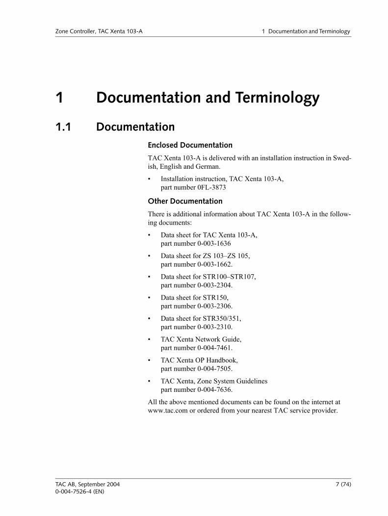
1.1 DocumentationEnclosed Documentation
TAC Xenta 103-A is delivered with an installation instruction in Swed-ish, English and German.
Installation instruction, TAC Xenta 103-A, part number 0FL-3873
Other Documentation
There is additional information about TAC Xenta 103-A in the follow-ing documents:
Data sheet for TAC Xenta 103-A,part number 0-003-1636
Data sheet for ZS 103ZS 105,part number 0-003-1662.
Data sheet for STR100STR107,part number 0-003-2304.
Data sheet for STR150,part number 0-003-2306.
Data sheet for STR350/351,part number 0-003-2310.
TAC Xenta Network Guide,part number 0-004-7461.
TAC Xenta OP Handbook,part number 0-004-7505.
TAC Xenta, Zone System Guidelinespart number 0-004-7636.
All the above mentioned documents can be found on the internet at www.tac.com or ordered from your nearest TAC service provider.
TAC AB, September 2004 7 (74)0-004-7526-4 (EN)
1 Documentation and Terminology Zone Controller, TAC Xenta 103-A
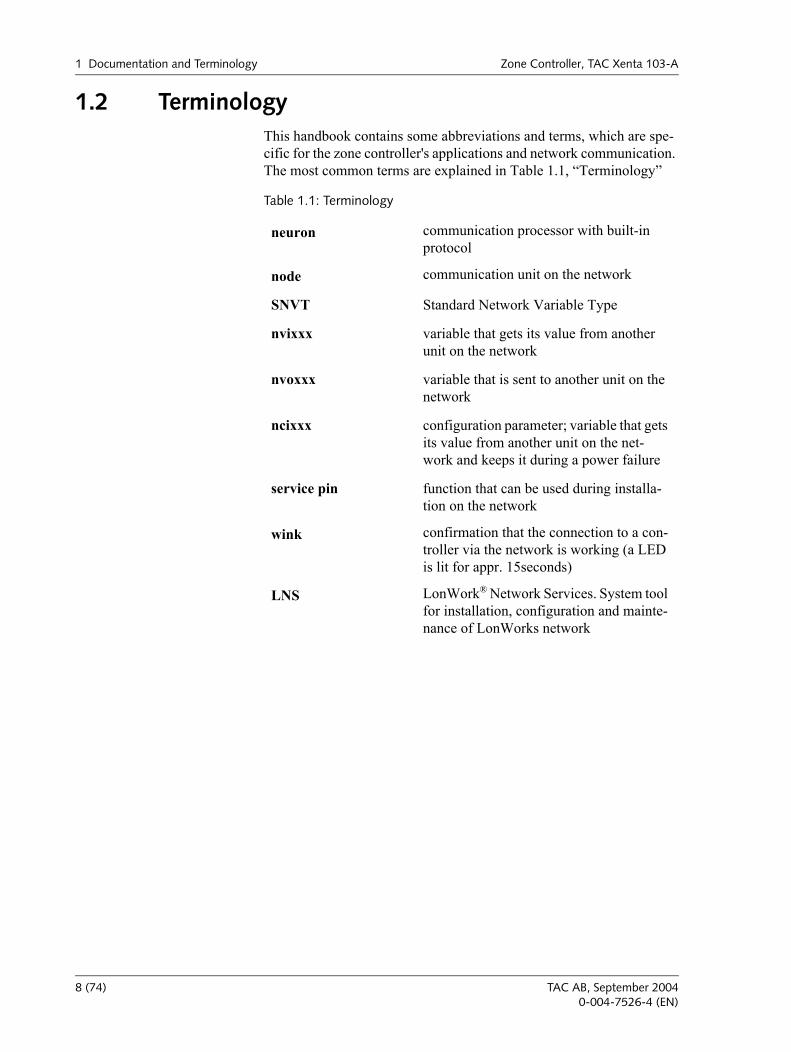
1.2 TerminologyThis handbook contains some abbreviations and terms, which are spe-cific for the zone controller's applications and network communication. The most common terms are explained in Table 1.1, Terminology
Table 1.1: Terminology
neuron communication processor with built-in protocol
node communication unit on the network
SNVT Standard Network Variable Type
nvixxx variable that gets its value from another unit on the network
nvoxxx variable that is sent to another unit on the network
ncixxx configuration parameter; variable that gets its value from another unit on the net-work and keeps it during a power failure
service pin function that can be used during installa-tion on the network
wink confirmation that the connection to a con-troller via the network is working (a LED is lit for appr. 15seconds)
LNS LonWork® Network Services. System tool for installation, configuration and mainte-nance of LonWorks network
8 (74) TAC AB, September 20040-004-7526-4 (EN)
Zone Controller, TAC Xenta 103-A 2 Zone Controller Xenta 103-A
2 Zone Controller Xenta 103-A
2.1 GeneralThe zone controller TAC Xenta 103-A is mainly intended for chilled ceilings in offices and other larger buildings. For chilled ceiling appli-cations, the zone temperature is controlled by modulation of the chilled water flow to ceiling elements, so called cooling baffles, and the hot water flow to radiators.
The Controller’s Basic Functions
The controller can handle the following applications:
Heating and cooling
Heating only
Cooling only, air and/or water
More About Functions
Apart from the controllers basic functions, there are a number of other functions for controlling the climate in the zone; these are described in detail in Chapter 5, Functional Description, on page 31. Additional external functions that can be connected are also described in this chap-ter, these include window contact sensor and occupancy sensor.
Communication
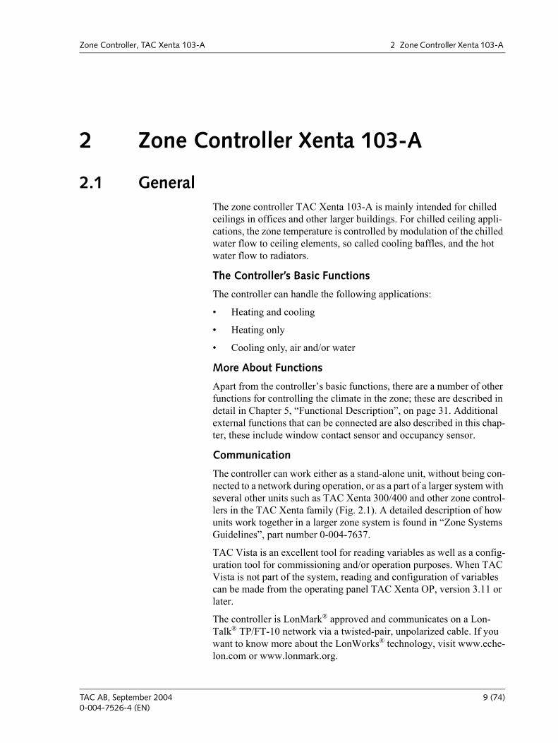
The controller can work either as a stand-alone unit, without being con-nected to a network during operation, or as a part of a larger system with several other units such as TAC Xenta 300/400 and other zone control-lers in the TAC Xenta family (Fig. 2.1). A detailed description of how units work together in a larger zone system is found in Zone Systems Guidelines, part number 0-004-7637.
TAC Vista is an excellent tool for reading variables as well as a config-uration tool for commissioning and/or operation purposes. When TAC Vista is not part of the system, reading and configuration of variables can be made from the operating panel TAC Xenta OP, version 3.11 or later.
The controller is LonMark® approved and communicates on a Lon-Talk® TP/FT-10 network via a twisted-pair, unpolarized cable. If you want to know more about the LonWorks® technology, visit www.eche-lon.com or www.lonmark.org.
TAC AB, September 2004 9 (74)0-004-7526-4 (EN)
2 Zone Controller Xenta 103-A Zone Controller, TAC Xenta 103-A
103-A103-A103-A103-A102-EF102-EF102-EF102-EF102-EF
101-2VF101-2VF101-2VF101-2VF101-2VF101-2VF102-B 102-B102-B
101-1VF 101-2VF101-1VF101-1VF101-1VF101-1VF101-1VF101-1VF101-1VF
AnalogI/O
DigitalI/O
TACXenta300
Router
Router
Router
TACXenta400
TACXenta400
3rdfloor
Office 3:1 Office 3:2 Office 3:3 Office 3:4 Office 3:5 Office 3:6 Office 3:7 Office 3:8 Office 3:9
2ndfloor
Office 2:1 Office 2:2 Office 2:3 Office 2:4 Office 2:5 Office 2:6Room 2:1Master
Room 2:2Slave
Room 2:3Slave
TAC Vista
1stfloor
Room1:1
Slave
Room 1:2Slave
Room1:4
Slave
Room 1:3Slave
Room 1:5Master
Office 1:1 Office 1:2 Office 1:3 Office 1:4
4thfloor
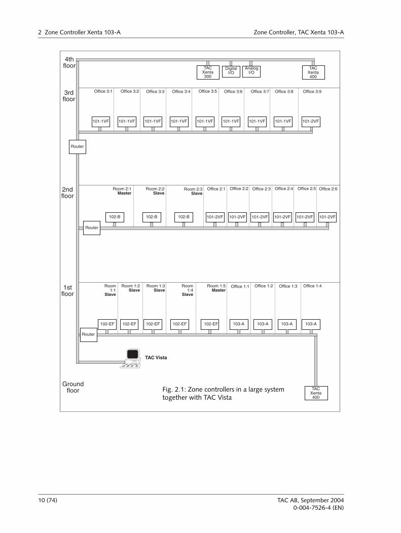
Groundfloor Fig. 2.1: Zone controllers in a large system
together with TAC Vista
10 (74) TAC AB, September 20040-004-7526-4 (EN)
Zone Controller, TAC Xenta 103-A 2 Zone Controller Xenta 103-A
2.2 Wall ModulesA temperature sensor must be mounted within in the zone to be con-trolled. In the STR series of wall modules the temperature sensor is combined with various types of user interface. Several STR models can be used with the TAC Xenta 103-A; the choice is determined by the desired functionality and user interface.
STR350/351. Wall unit with temperature sensor and LCD display. Extensive functionality for zone control. Communicates with the controller over LonWorks.
STR150. Wall unit with temperature sensor and LCD display. Incorporates the most common functions for zone control. One-way serial communication with the controller.
STR100-104. Wall module with temperature sensor and controls for the most common zone control functions. STR100-104 signals are hard-wired to TAC Xenta 103-A I/O.
2.2.1 STR350/351
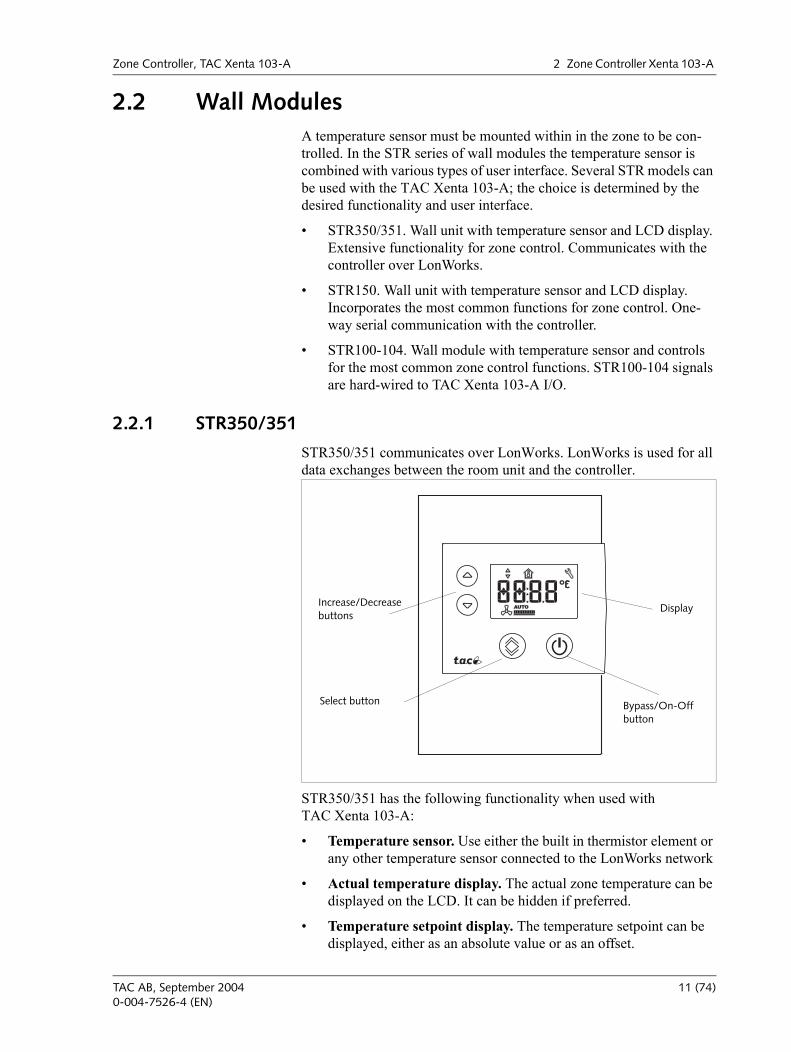
STR350/351 communicates over LonWorks. LonWorks is used for all data exchanges between the room unit and the controller.
STR350/351 has the following functionality when used with TAC Xenta 103-A:
Temperature sensor. Use either the built in thermistor element or any other temperature sensor connected to the LonWorks network
Actual temperature display. The actual zone temperature can be displayed on the LCD. It can be hidden if preferred.
Temperature setpoint display. The temperature setpoint can be displayed, either as an absolute value or as an offset.
Select button
Increase/Decreasebuttons
Bypass/On-Off button
Display
TAC AB, September 2004 11 (74)0-004-7526-4 (EN)
2 Zone Controller Xenta 103-A Zone Controller, TAC Xenta 103-A
Temperature setpoint adjustment. The temperature setpoint can be adjusted, either as an absolute value or as an offset.
Bypass or on/off button. The bypass function forces the control-ler to comfort mode for a configurable period of time. The same button can also be used as an on/off button.
Mode Indicator. An On/Off symbol in the LCD indicates the mode of the control.
See STR350/351 configuration and data sheets for more details about the technical characteristics listed above, additional functions and con-figuration details.
Use the LNS plug-in to configure STR350/351.
2.2.2 STR150
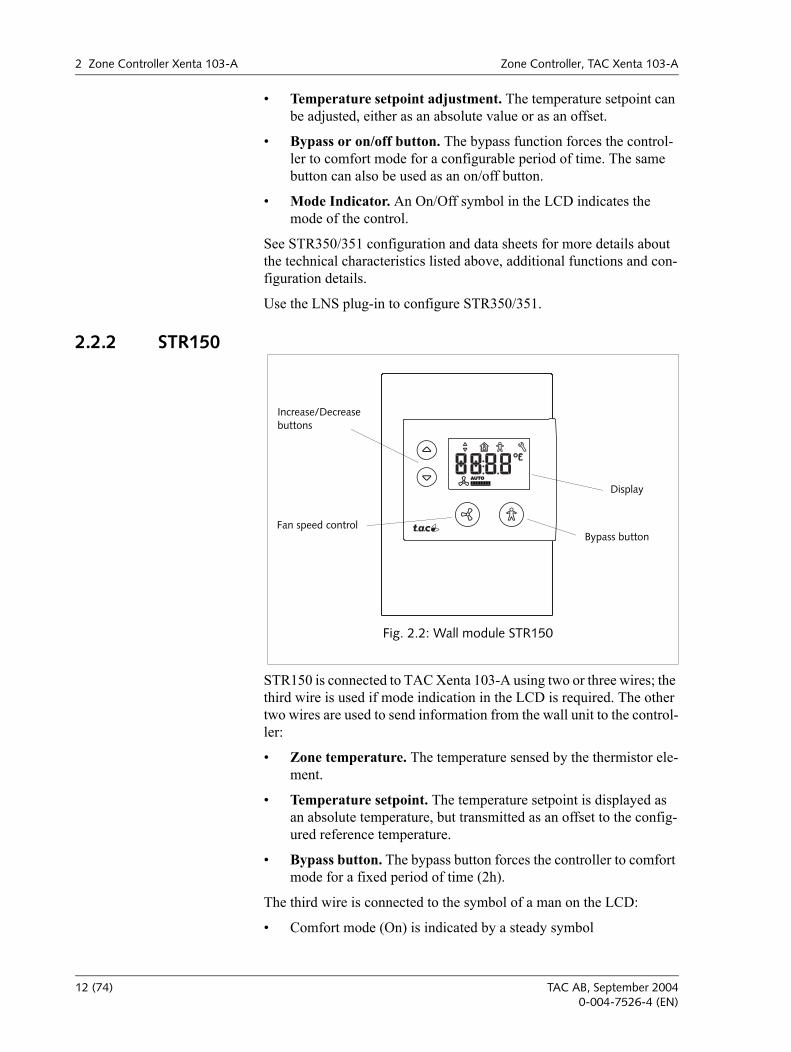
STR150 is connected to TAC Xenta 103-A using two or three wires; the third wire is used if mode indication in the LCD is required. The other two wires are used to send information from the wall unit to the control-ler:
Zone temperature. The temperature sensed by the thermistor ele-ment.
Temperature setpoint. The temperature setpoint is displayed as an absolute temperature, but transmitted as an offset to the config-ured reference temperature.
Bypass button. The bypass button forces the controller to comfort mode for a fixed period of time (2h).
The third wire is connected to the symbol of a man on the LCD:
Comfort mode (On) is indicated by a steady symbol
Fig. 2.2: Wall module STR150
Bypass button
Increase/Decreasebuttons
Fan speed control
Display
12 (74) TAC AB, September 20040-004-7526-4 (EN)
Zone Controller, TAC Xenta 103-A 2 Zone Controller Xenta 103-A
Economy (Standby) mode is indicated by a flashing symbol.
If the symbol is not shown (off) the zone is unoccupied.
There is no communication from the controller to the unit. This means that if a setpoint is changed using TAC Vista, the new value cannot be displayed on STR150.
STR150 is configured using the buttons and display on the unit. See STR150 configuration and data sheets for details.
2.2.3 STR100-104
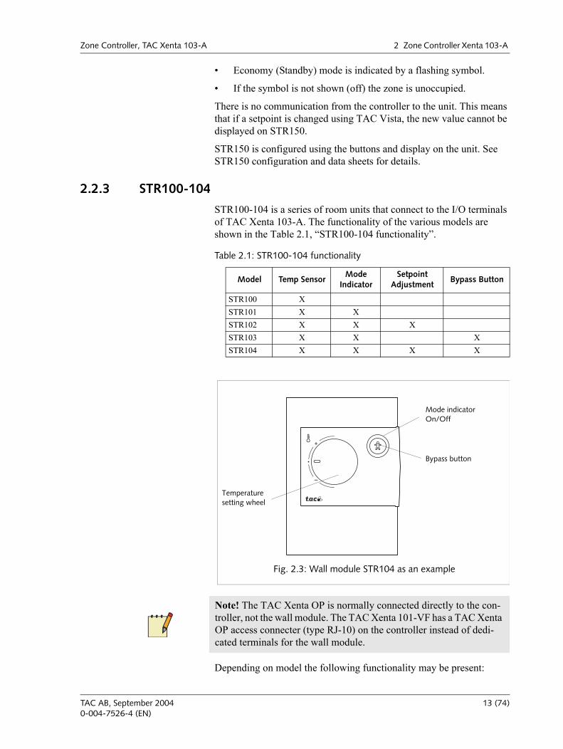
STR100-104 is a series of room units that connect to the I/O terminals of TAC Xenta 103-A. The functionality of the various models are shown in the Table 2.1, STR100-104 functionality.
Depending on model the following functionality may be present:
Table 2.1: STR100-104 functionality
Model Temp SensorMode
IndicatorSetpoint
AdjustmentBypass Button
STR100 XSTR101 X XSTR102 X X XSTR103 X X XSTR104 X X X X
Fig. 2.3: Wall module STR104 as an example
Mode indicatorOn/Off
Bypass button
Temperature setting wheel
Note! The TAC Xenta OP is normally connected directly to the con-troller, not the wall module. The TAC Xenta 101-VF has a TAC Xenta OP access connecter (type RJ-10) on the controller instead of dedi-cated terminals for the wall module.
TAC AB, September 2004 13 (74)0-004-7526-4 (EN)
2 Zone Controller Xenta 103-A Zone Controller, TAC Xenta 103-A
Temperature Sensor. All models have a 1.8Kohms@25°C ther-mistor element.
Temperature Adjustment. The temperature setpoint can be adjusted. Using the plastic keys on the rear of the core panel the adjustment range can be set.
Mode Indicator. The green LED indicates the control mode:
Comfort mode (On) is indicated by a steady green light
Economy (Standby) mode is indicated by a flashing green light.
If the LED is off the zone is unoccupied.
Bypass button. The bypass button forces the controller to comfort mode for a configurable period of time.
See STR100-107 data sheet and installation sheet for details.
2.2.4 Wall Module Configuration
Wall Module Choice
STR150 is enabled by nciAppOptions bit 14:
0 = ZS, STR100-104 or STR350/351 (default)
1 = STR150
This can be set using the LonMaker Xenta100 plug-ins in Toolpack ver-sion 2.01 or higher, or by means of TAC Xenta OP.
Initial Start Up Status
SpaceTemp in the application is set to +20.00 Celsius (This can be read in nvoSpaceTemp but not in the nviSpaceTemp)
Fan is set to Fan Auto
TAC Xenta can now accept data from the STR module.
If no room temperature readings are received within 10 minutes, the SpaceTemp in the application is set to invalid. This is shown as invalid in nvoSpaceTemp.
When the first update is received, then the 10-minute limit is changed to 5 minutes.
Unless there is a restart, the Offset + Fan values are not cleared and the last value is valid..
Fore more information on how to configure and engineer the STR series of wall modules see respective product documents.
14 (74) TAC AB, September 20040-004-7526-4 (EN)
Zone Controller, TAC Xenta 103-A 2 Zone Controller Xenta 103-A
2.3 Applications
2.3.1 General
The zone controller TAC Xenta 103-A is mainly designed for chilled ceilings in offices and other larger buildings. For chilled ceiling appli-cations, the zone temperature is controlled by modulation of the chilled water flow to ceiling elements, so called cooling baffles, and the hot water flow to radiators.
Air quality control, window contact sensor and the occupancy sensor, are described in detail in:
Chapter 5.3.4, Air Quality Control, on page 40,
Chapter 5.3.5, Window Contact, on page 41,
Chapter 5.3.6, Occupancy Sensor, on page 41.
2.3.2 The Zone Controller TAC Xenta 103-A
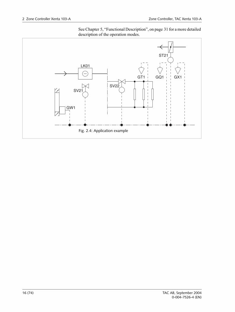
TAC Xenta 103-A can control a damper, used to cool the zone and to maintain the air quality. If the air quality is to be controlled, you need a carbon dioxide sensor, which is connected to, or send an SNVT, to the controller.
The temperature in the zone is kept constant by sequence control by the heating valve SV22, the air damper ST21 and the cooling valve SV21. When the cooling demand increases, the following occur:
1 The heating valve closes.
2 The the air damper, which is limited to its minimum and maximum positions, opens.
3 The cooling valve opens.
4 When the cooling demand decreases, the sequence is run in the opposite order.
There is a possibilty to connect a carbon dioxide sensor to the controller and thus control the carbon dioxide level in the zone by modulating the air volume to the zone. When the carbon dioxide level passes a certain limit, the controller starts increasing the air flow to the zone. The posi-tion of the damper thus depends on the temperature control, the air qual-ity control, and the minimum and maximum air flow limits.
When someone opens a window, the controller is stopped by the win-dow contact sensor GW1. To avoid too low a temperature in the zone, the controller turns to heating if the zone temperature falls below 10 °C.
The occupancy sensor GX1 checks if someone is present in the zone and also gives the possibility to switch between operation modes.
TAC AB, September 2004 15 (74)0-004-7526-4 (EN)
2 Zone Controller Xenta 103-A Zone Controller, TAC Xenta 103-A
See Chapter 5, Functional Description, on page 31 for a more detailed description of the operation modes.
GW1
SV21SV22
LK01
GQ1 GX1GT1
ST21
Fig. 2.4: Application example
16 (74) TAC AB, September 20040-004-7526-4 (EN)
Zone Controller, TAC Xenta 103-A 3 Installation
3 Installation
3.1 Mechanical Installation
3.1.1 Fitting
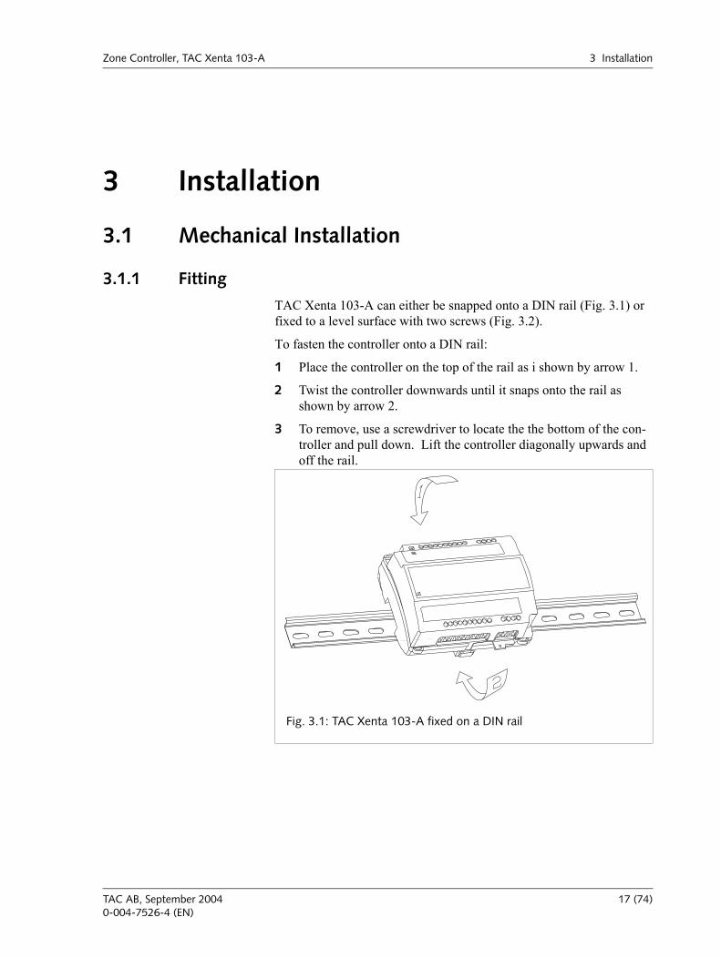
TAC Xenta 103-A can either be snapped onto a DIN rail (Fig. 3.1) or fixed to a level surface with two screws (Fig. 3.2).
To fasten the controller onto a DIN rail:
1 Place the controller on the top of the rail as i shown by arrow 1.
2 Twist the controller downwards until it snaps onto the rail as shown by arrow 2.
3 To remove, use a screwdriver to locate the the bottom of the con-troller and pull down. Lift the controller diagonally upwards and off the rail.
Fig. 3.1: TAC Xenta 103-A fixed on a DIN rail
TAC AB, September 2004 17 (74)0-004-7526-4 (EN)
3 Installation Zone Controller, TAC Xenta 103-A
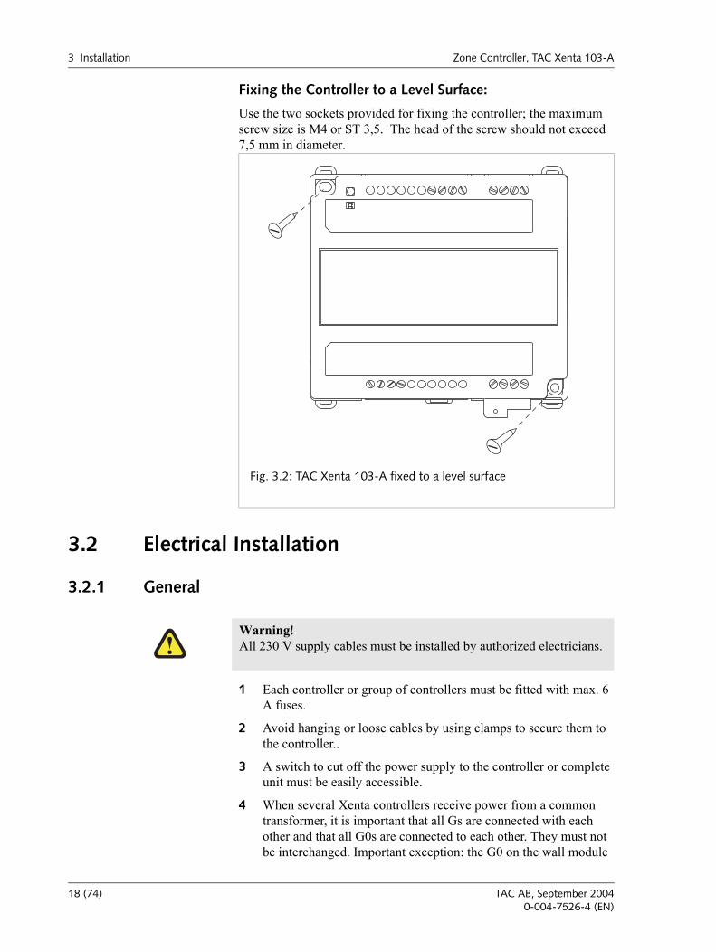
Fixing the Controller to a Level Surface:
Use the two sockets provided for fixing the controller; the maximum screw size is M4 or ST 3,5. The head of the screw should not exceed 7,5 mm in diameter.
3.2 Electrical Installation
3.2.1 General
1 Each controller or group of controllers must be fitted with max. 6 A fuses.
2 Avoid hanging or loose cables by using clamps to secure them to the controller..
3 A switch to cut off the power supply to the controller or complete unit must be easily accessible.
4 When several Xenta controllers receive power from a common transformer, it is important that all Gs are connected with each other and that all G0s are connected to each other. They must not be interchanged. Important exception: the G0 on the wall module
Fig. 3.2: TAC Xenta 103-A fixed to a level surface
!Warning! All 230 V supply cables must be installed by authorized electricians.
18 (74) TAC AB, September 20040-004-7526-4 (EN)
Zone Controller, TAC Xenta 103-A 3 Installation
should be connected to the terminal OP on the controller and not to the other G0s. Instead it should be connected to the terminal OP on the controller. The G0 should be grounded at the transformer to prevent interference.
5 To ensure that the specified measuring accuracy is achieved, the two M terminals must be connected to the wall module.
NOTE: This equipment has been tested and found to comply with the limits for a Class B digital device, pursuant to part 15 of the FCC Rules. These limits are designed to provide reasonable protection against harmful interference in a residential installation. This equipment gener-ates, uses and can radiate radio frequency energy and, if not installed and used in accordance with the instructions, may cause harmful inter-ference to radio communications. However, there is no guarantee that interference will not occur in a particular installation. If this equipment does cause harmful interference to radio or television reception, which can be determined by turning the equipment off and on, the user is encouraged to try to correct the interference by one or more of the fol-lowing measures:
Reorient or relocate the receiving antenna.
Increase the separation between the equipment and receiver.
Connect the equipment into an outlet on a circuit different from that to which the receiver is connected.
Consult the dealer or an experienced radio/TV technician for help.
Safety Standard
Transformers supplying the controller must comply to the safety stan-dard EN 60 742 or any other relevant safety standard for ELV, 24 V AC, ETL listing: UL 3111-1, first version and CAN/CSA C22.2 No. 1010.1-92. When connecting equipment that has an independent power supply, for example an occupancy sensor, this power supply must also comply with this norm.
Cable Lengths
For information on communication cable lengths, see TAC Xenta Net-work Guide, part number 0-004-7461. For all other cables, maximum length is 30 m and min. area is 0,7 mm2 .
Wall Modules
The STR100-104 is primarily intended for use with the Xenta 103-A. The wall module STR150 can also be used, but in this case the fan speed button is not used. For more information about how to connect and con-figure the wall modules, please refer to the documentation for each respective product.
TAC AB, September 2004 19 (74)0-004-7526-4 (EN)
3 Installation Zone Controller, TAC Xenta 103-A
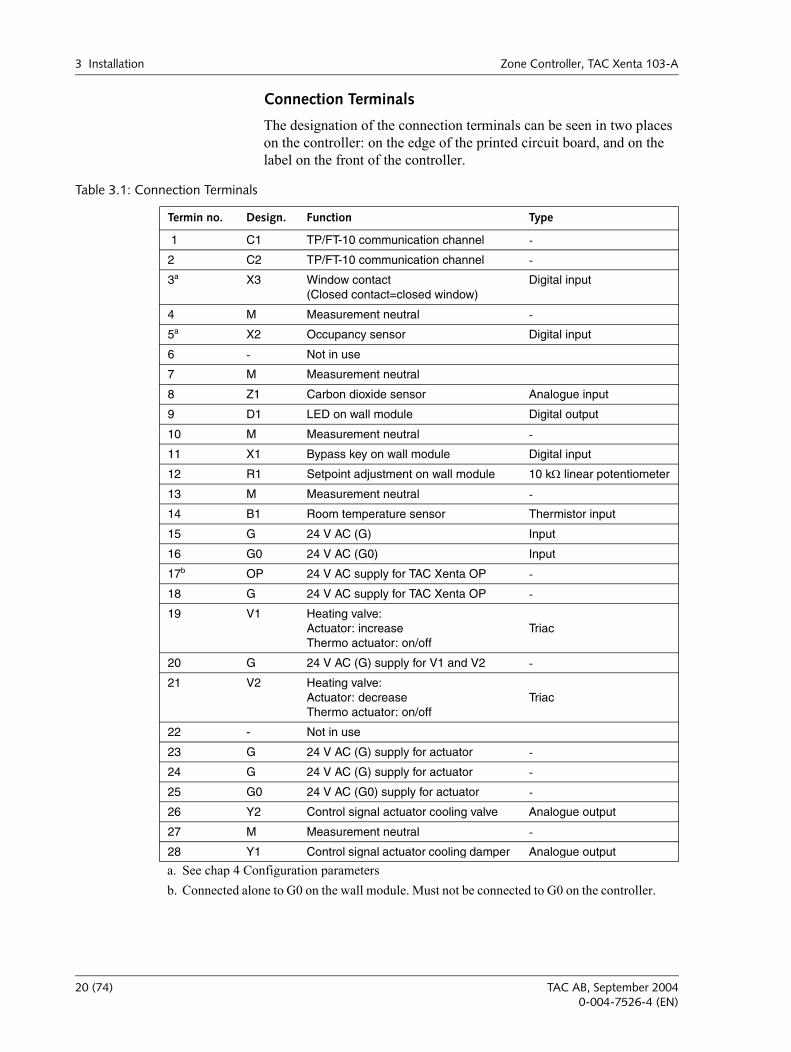
Connection Terminals
The designation of the connection terminals can be seen in two places on the controller: on the edge of the printed circuit board, and on the label on the front of the controller.
Table 3.1: Connection Terminals
Termin no. Design. Function Type
1 C1 TP/FT-10 communication channel -
2 C2 TP/FT-10 communication channel -
3a X3 Window contact (Closed contact=closed window)
Digital input
4 M Measurement neutral -
5a X2 Occupancy sensor Digital input
6 - Not in use
7 M Measurement neutral
8 Z1 Carbon dioxide sensor Analogue input
9 D1 LED on wall module Digital output
10 M Measurement neutral -
11 X1 Bypass key on wall module Digital input
12 R1 Setpoint adjustment on wall module 10 kΩ linear potentiometer
13 M Measurement neutral -
14 B1 Room temperature sensor Thermistor input
15 G 24 V AC (G) Input
16 G0 24 V AC (G0) Input
17b OP 24 V AC supply for TAC Xenta OP -
18 G 24 V AC supply for TAC Xenta OP -
19 V1 Heating valve: Actuator: increase Thermo actuator: on/off
Triac
20 G 24 V AC (G) supply for V1 and V2 -
21 V2 Heating valve: Actuator: decreaseThermo actuator: on/off
Triac
22 - Not in use
23 G 24 V AC (G) supply for actuator -
24 G 24 V AC (G) supply for actuator -
25 G0 24 V AC (G0) supply for actuator -
26 Y2 Control signal actuator cooling valve Analogue output
27 M Measurement neutral -
28 Y1 Control signal actuator cooling damper Analogue output
a. See chap 4 Configuration parametersb. Connected alone to G0 on the wall module. Must not be connected to G0 on the controller.
20 (74) TAC AB, September 20040-004-7526-4 (EN)
Zone Controller, TAC Xenta 103-A 3 Installation
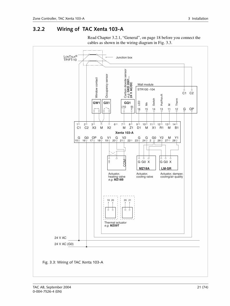
3.2.2 Wiring of TAC Xenta 103-A
Read Chapter 3.2.1, “General”, on page 18 before you connect the cables as shown in the wiring diagram in Fig. 3.3.
G G0
C2 X3 M M MM Z1 X1 R1 B1
OP V1 Y2 Y1
D1
G
C1
GG G
1 2 3 6 7 8 9 10 11 12 13 14
15 16 17 18 19 20 21 22 23 24 2 26 27 28
X2
G0 MV2
Xenta 103-A
GW1 GQ1GX1
– +
24 V AC
24 V AC (G0)
⇑
CO
M G G0 X
LM-SR
G G0 X
MZ18A
9)(10
19 20 2120
LONTALK®
TP/FT-10
Win
dow
con
tact
Occ
upan
cy s
enso
r
Junction box
Wall module
Actuator,heating valvee.g. MZ18B
Car
bon
diox
ide
sens
ore.
g. G
KD
200
1...
24 V
AC
/DC
Actuator,cooling valve
Thermal actuatore.g. MZ09T
Actuator, damper,cooling/air quality
C2C1
G OP
M The
rm
LED
Pot
/Pot
+R
Mx
Sw
itch
121113141516
STR100 -104
Fig. 3.3: Wiring of TAC Xenta 103-A
TAC AB, September 2004 21 (74)0-004-7526-4 (EN)
3 Installation Zone Controller, TAC Xenta 103-A
3.3 Commissioning
3.3.1 General
Once the mechanical and electrical installations have been completed the controller can be commissioned. This means:
Installing the controller on the network, setting node status and giving it an address.
Set the controller's configuration parameters.
Bind network variables.
Test the functions.
Before commissioning a complete zone system, read the manual TAC Xenta - Zone Systems Guideline. You could use TAC Xenta OP for setting the basic parameters. Use a network management tool or TAC Vista for commissioning the controller on the network and then do the rest of the commissioning.
How to use the TAC Xenta 100 as a stand-alone unit:
1 Use TAC Xenta OP to set the node status to "Configured".
2 Use TAC Xenta OP to set the basic parameters.
3 Use TAC Xenta OP to set all other parameters and variables.
Commissioning can also be achieved using a network management tool.
3.3.2 Node Status
The node status indicates which network configuration or program mode the controller is in. The node status can be changed using TAC Vista (version 3.1 or later), a network management tool. TAC Xenta OP can also be used on some occasions. The controller can be in these states:
Unconfigured
The controller is not configured when it leaves the factory. Neither the program nor the network communication are running. The service light emitting diode is flashing.
The controller must be configured before it can operate in a network (on line), see below.
You cannot set configuration parameters or network variables in this state.
Configured, Online
Use TAC Xenta OP, TAC Vista or a network management tool to change the status to configured. When this has been done, the program
22 (74) TAC AB, September 20040-004-7526-4 (EN)
Zone Controller, TAC Xenta 103-A 3 Installation
and the network communication will be fully operational. The service LED is off. This is the normal state for a controller when it is operating.
The controller will use the address given by the tool during configura-tion. As TAC Xenta OP cannot be used to set an address, all controllers are given a default address. This means that TAC Xenta 100 can only be used as a stand-alone controller and cannot be used in a network..
The parameters and variables can now be set.
Configured, Soft Online
A network management tool is needed for this operation. The controller is programed and configured for a network, but the program and com-munications are idle. The light emitting diode is off. If the controller is reset, it will go into configured, online.
Configured, Hard Online
A network management tool is needed for this operation. The controller is programed and configured for a network, but the program and com-munications are idle. The light emitting diode is off. If the controller is reset, it will go remain in this state.
Without a Program and not Configured
This states indicates that there is something wrong with the controller. No program can be detected. The light emitting diode is lit.
3.3.3 Configuration Parameters (nci's)
TAC Xenta 100 has a number of configuration parametersthat can be used to set the parameters of the controller. (See Chapter 4, Configu-ration Parameters, on page 25.) There are also network variables to control the controller during when it is operating.
Use the commissioning protocol in Appendix B to write down your set-tings when commissioning. See Chapter 8, Communication, on page 53, for more information about all parameters and variables, such as their index, accepted values, normal values.
3.3.4 Network Installation
For network installation, you need either a network management tool (LNS based or not) or TAC Vista. Examples of network management tools are MetraVision and ICELAN-G. (For more information see TAC Xenta, Guidelines for zone applications.)
The installation requires two steps:
1 Feed information about the controllers unique neuron-ID into the network management tools data base.
2 Allow the network management tool to install the controller on the network. The controller will automatically be given an address.
TAC AB, September 2004 23 (74)0-004-7526-4 (EN)
3 Installation Zone Controller, TAC Xenta 103-A
There are two ways to feed the neuron-ID into the data base:
1 Manually feed the neuron-ID into the network management tool. To make this easier you can use a bar code reader to read the detachable ID-neuron label, that is attached to every controller. It can be a good idea to collect these labels when you make the basic configuration, and stick them to a form, drawing or similar. There is a form for this purpose in the "TAC Xenta, Guidelines for zone applications" manual.
2 Use the service pin function. You can only do this when the con-troller is connected to the network. There is a service pin key in a hole in the upper left hand corner of the controller by terminal C1. Push the key to instruct the controller to send out its neuron-ID. The network management tool can then read the neuron-ID from the network and to save it in its data base.
3.3.5 Network Variable Binding
The binding method is determined by the type of network management tool to be used. Detailed information can be found in the tools docu-mentation. A description of how to bind network variables with Metra Vision can be found in the "TAC Xenta Network manual".
Binding network variables is not an issue when the controller is used in a stand-alone operation.
3.3.6 Function Test
Check that the controller controller works as intended.
All the controllers functions are described in Chapter 5, Functional Description, on page 31.
24 (74) TAC AB, September 20040-004-7526-4 (EN)
Zone Controller, TAC Xenta 103-A 4 Configuration Parameters
4 Configuration ParametersAll communication with the controller is made using network variables.
ncis are used to configure the controller. ncis are normally set during commissioning, and are not altered during normal opera-tion (the parameters are stored in a special memory, and can be changed a maximum of 10 000 times).
nvis are used during operation.
nvos are output variables, which the controller sends out on the network.
Please see Chapter 8, Communication, on page 53 for a detailed information about accepted values and normal values for all parameters. All configuration parameters have default values on delivery.
TAC AB, September 2004 25 (74)0-004-7526-4 (EN)
4 Configuration Parameters Zone Controller, TAC Xenta 103-A
4.1 Basic ParametersnciAppOptions
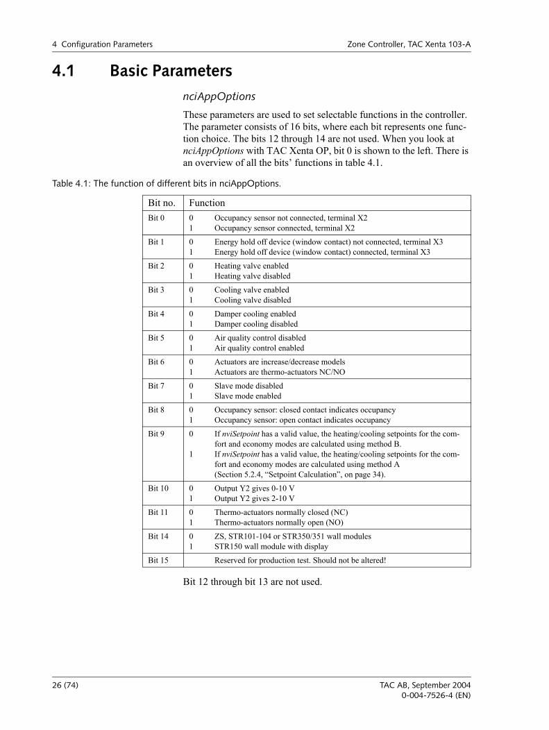
These parameters are used to set selectable functions in the controller. The parameter consists of 16 bits, where each bit represents one func-tion choice. The bits 12 through 14 are not used. When you look at nciAppOptions with TAC Xenta OP, bit 0 is shown to the left. There is an overview of all the bits functions in table 4.1.
Bit 12 through bit 13 are not used.
Table 4.1: The function of different bits in nciAppOptions.
Bit no. FunctionBit 0 0
1Occupancy sensor not connected, terminal X2Occupancy sensor connected, terminal X2
Bit 1 01
Energy hold off device (window contact) not connected, terminal X3Energy hold off device (window contact) connected, terminal X3
Bit 2 01
Heating valve enabledHeating valve disabled
Bit 3 01
Cooling valve enabledCooling valve disabled
Bit 4 01
Damper cooling enabledDamper cooling disabled
Bit 5 01
Air quality control disabledAir quality control enabled
Bit 6 01
Actuators are increase/decrease modelsActuators are thermo-actuators NC/NO
Bit 7 01
Slave mode disabledSlave mode enabled
Bit 8 01
Occupancy sensor: closed contact indicates occupancyOccupancy sensor: open contact indicates occupancy
Bit 9 0
1
If nviSetpoint has a valid value, the heating/cooling setpoints for the com-fort and economy modes are calculated using method B.If nviSetpoint has a valid value, the heating/cooling setpoints for the com-fort and economy modes are calculated using method A (Section 5.2.4, Setpoint Calculation, on page 34).
Bit 10 01
Output Y2 gives 0-10 VOutput Y2 gives 2-10 V
Bit 11 01
Thermo-actuators normally closed (NC)Thermo-actuators normally open (NO)
Bit 14 01
ZS, STR101-104 or STR350/351 wall modulesSTR150 wall module with display
Bit 15 Reserved for production test. Should not be altered!
26 (74) TAC AB, September 20040-004-7526-4 (EN)
Zone Controller, TAC Xenta 103-A 4 Configuration Parameters
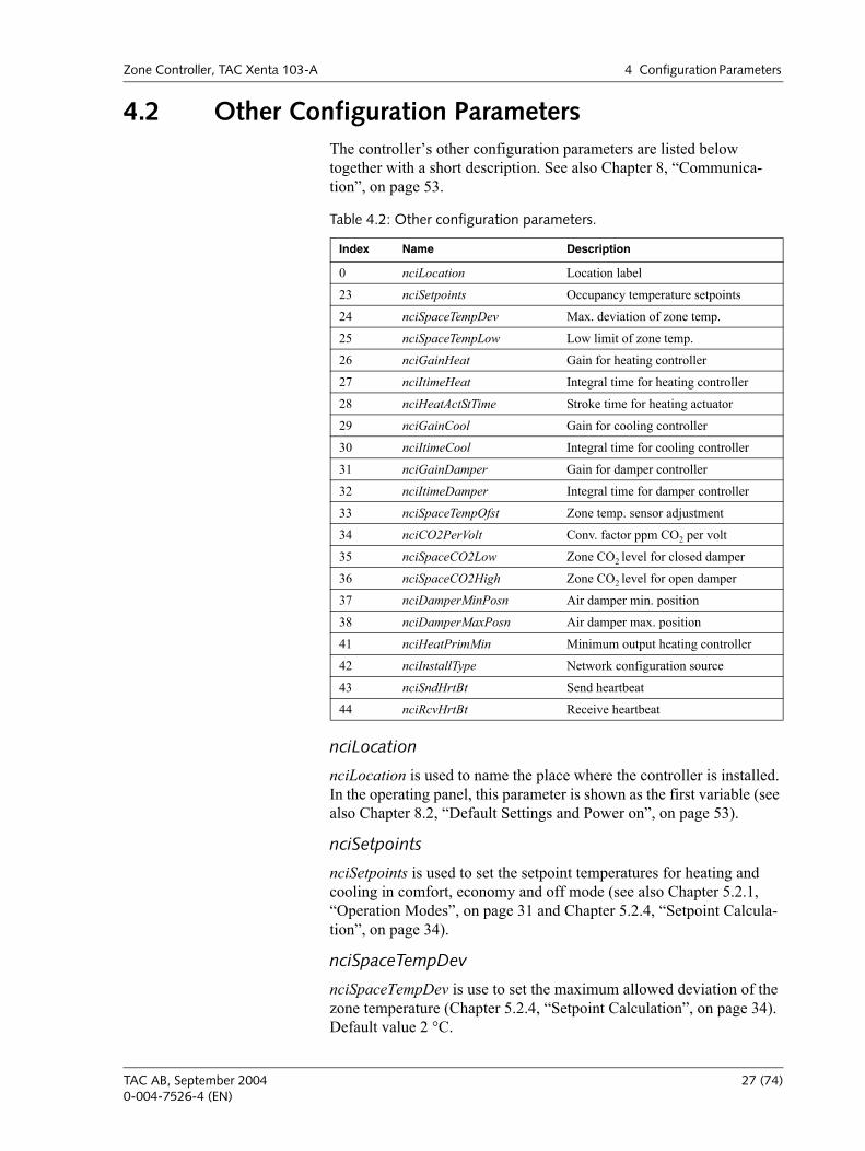
4.2 Other Configuration ParametersThe controllers other configuration parameters are listed below together with a short description. See also Chapter 8, Communica-tion, on page 53.
nciLocation
nciLocation is used to name the place where the controller is installed. In the operating panel, this parameter is shown as the first variable (see also Chapter 8.2, Default Settings and Power on, on page 53).
nciSetpoints
nciSetpoints is used to set the setpoint temperatures for heating and cooling in comfort, economy and off mode (see also Chapter 5.2.1, Operation Modes, on page 31 and Chapter 5.2.4, Setpoint Calcula-tion, on page 34).
nciSpaceTempDev
nciSpaceTempDev is use to set the maximum allowed deviation of the zone temperature (Chapter 5.2.4, Setpoint Calculation, on page 34). Default value 2 °C.
Table 4.2: Other configuration parameters.
Index Name Description
0 nciLocation Location label
23 nciSetpoints Occupancy temperature setpoints
24 nciSpaceTempDev Max. deviation of zone temp.
25 nciSpaceTempLow Low limit of zone temp.
26 nciGainHeat Gain for heating controller
27 nciItimeHeat Integral time for heating controller
28 nciHeatActStTime Stroke time for heating actuator
29 nciGainCool Gain for cooling controller
30 nciItimeCool Integral time for cooling controller
31 nciGainDamper Gain for damper controller
32 nciItimeDamper Integral time for damper controller
33 nciSpaceTempOfst Zone temp. sensor adjustment
34 nciCO2PerVolt Conv. factor ppm CO2 per volt
35 nciSpaceCO2Low Zone CO2 level for closed damper
36 nciSpaceCO2High Zone CO2 level for open damper
37 nciDamperMinPosn Air damper min. position
38 nciDamperMaxPosn Air damper max. position
41 nciHeatPrimMin Minimum output heating controller
42 nciInstallType Network configuration source
43 nciSndHrtBt Send heartbeat
44 nciRcvHrtBt Receive heartbeat
TAC AB, September 2004 27 (74)0-004-7526-4 (EN)
4 Configuration Parameters Zone Controller, TAC Xenta 103-A
nciSpaceTempLow
nciSpaceTempLow is used to set the lowest allowed zone temperature (Chapter 5.3.8, Alarm, on page 43). Default value 10 °C.
nciGainHeat, nciGainCool
nciGainHeat and nciGainCool are used to set the gain for the heating/cooling controllers. Default value 25.
nciItimeHeat, nciItimeCool
nciItimeHeat and nciItimeCool are used to set the I-time for the heating/cooling controllers. Default values 1500 s (25 min) / 900 s (15 min).
nciHeatActStTime
nciHeatActStTime is set according to the runtime of the actuator. Default value 165 s.
nciGainDamper
nciGainDamper gives the gain for cooling for the damper. Default value 25.
nciItimeDamper
nciItimeDamper is used to set the I-time for cooling for the damper. Default value 900 s (15 min).
nciSpaceTempOfst
nciSpaceTempOfst is used to adjust the temperature setpoints at the wall module. Default value 0.0 °C.
nciCO2PerVolt
nciCO2PerVolt holds the conversion factor to get the carbon dioxide level in the zone by means of the output from the carbon dioxide sensor. Default value 220 ppm/V.
nciSpaceCO2Low
nciSpaceCO2Low is used to set the carbon dioxide level at closed damper. Default value 400 ppm.
nciSpaceCO2High
nciSpaceCO2High is used to set the carbon dioxide level at open damper. Default value 1000 ppm.
nciDamperMinPosn
nciDamperMinPosn is used to set the smallest damper opening allowed. Default value 30%.
28 (74) TAC AB, September 20040-004-7526-4 (EN)
Zone Controller, TAC Xenta 103-A 4 Configuration Parameters
nciDamperMaxPosn
nciDamperMaxPosn is used to set the largest damper opening allowed. Default value 100%.
nciHeatPrimMin
nciHeatPrimMin is used to set the smallest heating valve opening allowed (see also Chapter 5.3.7, Minimum Value for Heating Valve, on page 42). Default value 0%.
nciSndHrtBt
nciSndHrtBt is used to determine how often the nvos, which are trans-mitted continuously on the net, should be sent ( see also Chapter 8.3, Monitoring Network Variables, Heartbeat, on page 54).
nciRcvHrtBt
nciRcvHrtBt is used to determine how long time max. there may be between updating the nvis, for which the controller expects continuous updating (see alsoChapter 8.3, Monitoring Network Variables, Heart-beat, on page 54).
TAC AB, September 2004 29 (74)0-004-7526-4 (EN)
4 Configuration Parameters Zone Controller, TAC Xenta 103-A
30 (74) TAC AB, September 20040-004-7526-4 (EN)
Zone Controller, TAC Xenta 103-A 5 Functional Description
5 Functional Description
5.1 GeneralThe controllers function is determined by its node status, operation modes and the methods used to force the controller for well-adapted zone temperatur control. The controller, which has a built-in damper function, measures the zone temperature, and uses various methods to calculate setpoints. Apart from the basic functions, the controller can also be used to control the climate in the zone.
Each section in this chapter ends with information about how network variables are used in the current control situation. If you need details about the network variables characteristics, such as default values and accepted values, see Chapter 8, Communication, on page 53.
5.2 The Controller’s Basic Functions
5.2.1 Operation Modes
The controller has four selectable operation modes:
Comfort
Economy
Bypass
Off
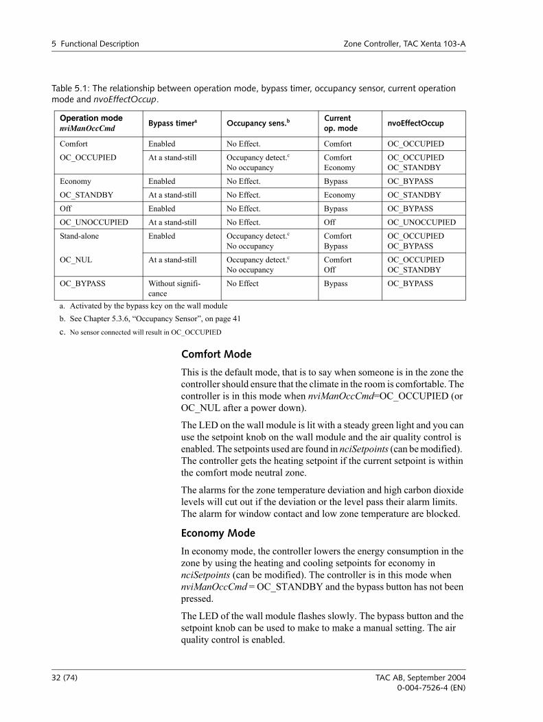
The operation mode is controlled by nviManOccCmd, but is aslo influ-enced by occupancy sensors and the bypass key on the wall module. The relationship between operation modes is shown in Table 5.1, The relationship between operation mode, bypass timer, occupancy sensor, current operation mode and nvoEffectOccup.
TAC AB, September 2004 31 (74)0-004-7526-4 (EN)
5 Functional Description Zone Controller, TAC Xenta 103-A
Comfort Mode
This is the default mode, that is to say when someone is in the zone the controller should ensure that the climate in the room is comfortable. The controller is in this mode when nviManOccCmd=OC_OCCUPIED (or OC_NUL after a power down).
The LED on the wall module is lit with a steady green light and you can use the setpoint knob on the wall module and the air quality control is enabled. The setpoints used are found in nciSetpoints (can be modified). The controller gets the heating setpoint if the current setpoint is within the comfort mode neutral zone.
The alarms for the zone temperature deviation and high carbon dioxide levels will cut out if the deviation or the level pass their alarm limits. The alarm for window contact and low zone temperature are blocked.
Economy Mode
In economy mode, the controller lowers the energy consumption in the zone by using the heating and cooling setpoints for economy in nciSetpoints (can be modified). The controller is in this mode when nviManOccCmd = OC_STANDBY and the bypass button has not been pressed.
The LED of the wall module flashes slowly. The bypass button and the setpoint knob can be used to make to make a manual setting. The air quality control is enabled.
Table 5.1: The relationship between operation mode, bypass timer, occupancy sensor, current operation mode and nvoEffectOccup.
Operation modenviManOccCmd
Bypass timera Occupancy sens.bCurrentop. mode
nvoEffectOccup
Comfort Enabled No Effect. Comfort OC_OCCUPIED
OC_OCCUPIED At a stand-still Occupancy detect.cNo occupancy
ComfortEconomy
OC_OCCUPIED OC_STANDBY
Economy Enabled No Effect. Bypass OC_BYPASS
OC_STANDBY At a stand-still No Effect. Economy OC_STANDBY
Off Enabled No Effect. Bypass OC_BYPASS
OC_UNOCCUPIED At a stand-still No Effect. Off OC_UNOCCUPIED
Stand-alone Enabled Occupancy detect.c No occupancy
ComfortBypass
OC_OCCUPIEDOC_BYPASS
OC_NUL At a stand-still Occupancy detect.cNo occupancy
ComfortOff
OC_OCCUPIEDOC_STANDBY
OC_BYPASS Without signifi-cance
No Effect Bypass OC_BYPASS
a. Activated by the bypass key on the wall moduleb. See Chapter 5.3.6, Occupancy Sensor, on page 41c. No sensor connected will result in OC_OCCUPIED
32 (74) TAC AB, September 20040-004-7526-4 (EN)
Zone Controller, TAC Xenta 103-A 5 Functional Description
The alarms for low zone temperature and window contact may cut out. The alarms for high carbon dioxide level and for zone temperature devi-ation are blocked.
Bypass Mode
The bypass key on the wall module is used if you occasionally want to change to comfort mode from economy or off mode.
When someone presses the bypass key on the wall module, the bypass timer starts and the controller turns to bypass mode. The bypass timer runs for two hours, and after , after which the controller changes opera-tion mode, see Table 5.1, The relationship between operation mode, bypass timer, occupancy sensor, current operation mode and nvoEffec-tOccup.. The controllers bypass mode acts as the comfort mode dur-ing those two hours and the setpoints and alarms operate as in comfort mode.
Off Mode
When the zone is not used for a longer period of time, the controller can be set to off mode. The controller is in this mode when nviManOccCmd=OC_UNOCCUPIED.
The light emitting diode on the wall module is out, and controls by heat-ing and cooling demand according to the setpoint in nciSetpoints.
The bypass key, the low zone temperature alarm and window contact alarm are not blocked. The air quality control is blocked, as well as the setpoint setting, the alarms for deviation in zone temperature and for high carbon dioxide level.
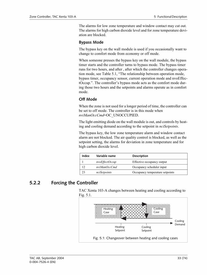
5.2.2 Forcing the Controller
TAC Xenta 103-A changes between heating and cooling according to Fig. 5.1.
Index Variable name Description
1 nvoEffectOccup Effective occupancy output
12 nviManOccCmd Occupancy scheduler input
23 nciSetpoints Occupancy temperature setpoints
HeatingCase
CoolingCase
HeatingSetpoint
CoolingSetpoint
CoolingDemand
Fig. 5.1: Changeover between heating and cooling cases
TAC AB, September 2004 33 (74)0-004-7526-4 (EN)
5 Functional Description Zone Controller, TAC Xenta 103-A
You can force the controller to heat only or cool only, just as you can force it to neither heat nor cool, and to run the fan only. This is achieved using nviApplicMode, see Table 5.2, nviApplicMode.
5.2.3 Measuring Zone Temperature
Measure the zone temperature either with a permanent thermistor sen-sor (the wall module) or with a LonTalk temperature sensor node con-nected to nviSpaceTemp. If nviSpaceTemp has a valid value the controller will use it, if it doesn't the thermistor value will be used. The thermistor value can be adjusted by nciSpaceTempOfst having received a value; this is added to the thermistor value. The value the controller uses is also put out on nvoSpaceTemp. If neither value is valid, nvoSpaceTemp will receive the off value.
nvoSpaceTemp is sent when it has changed by at least 0.1°C..
5.2.4 Setpoint Calculation
Zone Temperature Setpoints
nciSetpoints define six temperature setpoints. The smallest accepted deviation between the heating and cooling setpoints is 0,5 °C, and the heating setpoints must be lower than the cooling setpoints. If the heating setpoints are higher or equal to the cooling setpoints, the controller resets the heating setpoint to 0.5 °C lower than the cooling setpoint.
Table 5.2: nviApplicMode
nviApplicMode Forcing Description
HVAC_AUTO Automatic The controller automatically changes over between heating and cooling.
HVAC_HEAT Heating only The controller can only heat. The cooling setpoint is neglected. The air quality control is enabled and the damper is limited to its open and closed positions.
HVAC_COOL Cooling only The controller can only cool. The heating setpoint is neglected. The air quality control is enabled and the damper is limited to its open and closed positions.
HVAC_NIGHT_PURGE Night cooling
The controller can only cool with the air flow from the damper. The heating and cooling valves are closed. The air quality control is disabled.
HVAC_OFF Off Valves, dampers and air quality control are disabled. Only the low zone temperature protection is enabled.
Table 5.3:
Index Variable name Description
13 nviApplicMode Application mode input
Index Variable name Description
5 nvoSpaceTemp Zone temperature output
14 nviSpaceTemp Zone temperature input
33 nciSpaceTempOfst Zone temperature sensor adjustment
34 (74) TAC AB, September 20040-004-7526-4 (EN)
Zone Controller, TAC Xenta 103-A 5 Functional Description
Table 5.4, The setpoints in nciSetpoints. shows accepted values and default values for the six temperature setpoints in nciSetpoints.
The setpoints for comfort and economy mode are basic setpoints, which can be changed with nviSetpoint, nviSetPntOffset and the setpoint knob. The off mode setpoints are always valid.
Calculation
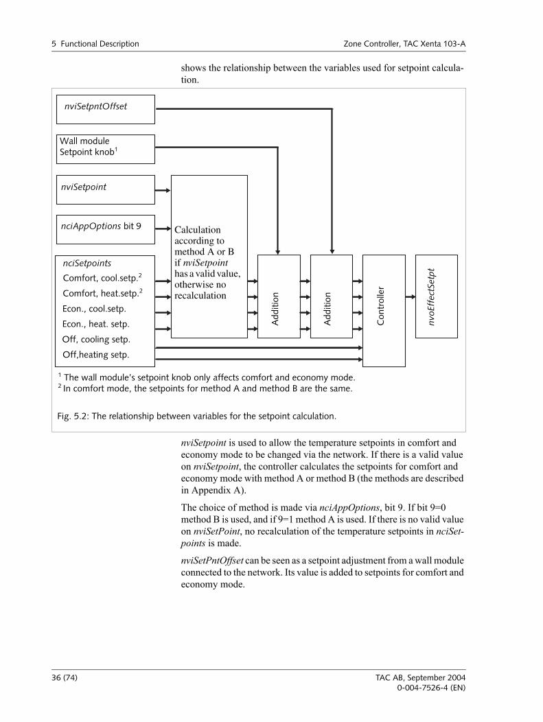
The current setpoint, nvoEffectSetpt, depends on the current operation mode (nvoEffectOccup), current operation mode, (nvoUnitStatus; mode), and nviSetpoint, nviSetpntOffset, nciAppOptions, nciSetpoints and a possible local setpoint adjustment via the wall module.Fig. 5.2
Table 5.4: The setpoints in nciSetpoints.
Setpoint Min. Max. Normal
Cooling setpoint comfort 10 °C 35 °C 23 °C
Heating setpoint comfort 10 °Ca
a. If the cooling setpoint is 10 °C, the heating setpoint is set to 9,5 °C.
35 °C 21 °C
Cooling setpoint economy 10 °C 35 °C 25 °C
Heating setpoint economy 10 °Ca 35 °C 19 °C
Cooling setpoint off 10 °C 35 °C 28 °C
Hetaing setpoint off 10 °Ca 35 °C 16 °C
TAC AB, September 2004 35 (74)0-004-7526-4 (EN)
5 Functional Description Zone Controller, TAC Xenta 103-A
shows the relationship between the variables used for setpoint calcula-tion.
nviSetpoint is used to allow the temperature setpoints in comfort and economy mode to be changed via the network. If there is a valid value on nviSetpoint, the controller calculates the setpoints for comfort and economy mode with method A or method B (the methods are described in Appendix A).
The choice of method is made via nciAppOptions, bit 9. If bit 9=0 method B is used, and if 9=1 method A is used. If there is no valid value on nviSetPoint, no recalculation of the temperature setpoints in nciSet-points is made.
nviSetPntOffset can be seen as a setpoint adjustment from a wall module connected to the network. Its value is added to setpoints for comfort and economy mode.
nviSetpntOffset
Wall moduleSetpoint knob1
nviSetpoint
nciAppOptions bit 9
nciSetpoints
Calculation according to method A or Bif nviSetpoint has a valid value, otherwise no recalculation
Add
ition
Add
ition
Con
trol
ler
nvoE
ffec
tSet
pt
Off, cooling setp.
Econ., heat. setp.
Econ., cool.setp.
Off,heating setp.
Comfort, heat.setp.2Comfort, cool.setp.2
Fig. 5.2: The relationship between variables for the setpoint calculation.
1 The wall module’s setpoint knob only affects comfort and economy mode.2 In comfort mode, the setpoints for method A and method B are the same.
36 (74) TAC AB, September 20040-004-7526-4 (EN)
Zone Controller, TAC Xenta 103-A 5 Functional Description
In Appendix A there are detailed calculation examples of setpoint cal-culations.
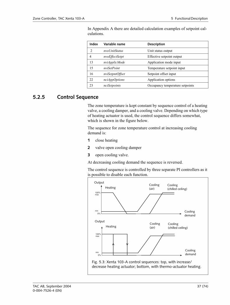
5.2.5 Control Sequence
The zone temperature is kept constant by sequence control of a heating valve, a cooling damper, and a cooling valve. Depending on which type of heating actuator is used, the control sequence differs somewhat, which is shown in the figure below.
The sequence for zone temperature control at increasing cooling demand is:
1 close heating
2 valve open cooling damper
3 open cooling valve.
At decreasing cooling demand the sequence is reversed.
The control sequence is controlled by three separate PI controllers as it is possible to disable each function.
Index Variable name Description
2 nvoUnitStatus Unit status output
4 nvoEffectSetpt Effective setpoint output
13 nviApplicMode Application mode input
15 nviSetPoint Temperature setpoint input
16 nviSetpntOffset Setpoint offset input
22 nciAppOptions Application options
23 nciSetpoints Occupancy temperature setpoints
100%
0%
max
min
Output
HeatingCooling(chilled ceiling)
Cooling demand
Cooling(air)
100%
0%
max
min
Output
HeatingCooling(chilled ceiling)
Cooling demand
Cooling(air)
Fig. 5.3: Xenta 103-A control sequences: top, with increase/decrease heating actuator; bottom, with thermo-actuator heating.
TAC AB, September 2004 37 (74)0-004-7526-4 (EN)
5 Functional Description Zone Controller, TAC Xenta 103-A
5.3 More About Functions
5.3.1 Heating Control
The heating control is done with an increase/decrease actuator or an on/off signal for thermo-actuators. Actuator is selected with bit 6 in nciAppOptions.
When the on/off signal (thermo-actuator) is selected, the outputs V1 and V2 are connected in parallel. The actuator type should be normally closed, i.e. a set output is the same as opening the valve.
A thermo-actuator is started when the zone temperature falls below the current setpoint and is turned off when the zone temperature passes the current setpoint. The change is performed with a 0.1°C hysteresis.
nvoHeatPrimary and the heating setpoint in nvoUnitStatus show the current heating output level. nvoHeatPrimary can be used to remote control a heating source.
Accepted values for these variables are from 0% to 100% of the heating capacity. The value 163.83% is sent as a not valid value to show that the heating step is blocked.
5.3.2 Cooling Control (Chilled Ceiling)
The cooling valve is controlled by an analogue output (0-10 V or 2-10 V), where 10 V corresponds to a completely open valve.
nvoCoolSecondary and the cooling setpoint in nvoUnitStatus show cur-rent output level for the chilled ceiling elements.
Heating control
Type: PI
Gain: 0–32.75; normal 25
I-time: 0–60 minutes, normal 25 minutes
Dead band: 0.2 °C
Run time: 5–600 s; normal 165 s
Control interval: 60 s
Index Variable name Description
2 nvoUnitStatus Unit status output
6 nvoHeatPrimary Heating control output
22 nciAppOptions Application options
26 nciGainHeat Gain for heating controller
27 nciItimeHeat Integral time for heating controller
38 (74) TAC AB, September 20040-004-7526-4 (EN)
Zone Controller, TAC Xenta 103-A 5 Functional Description
Accepted values for these variables are from 0% to 100% of the cooling capacity. The value 163.83% is sent as a not valid value to show that cooling via the chilled ceiling elements is blocked..
5.3.3 Cooling Controller (air)
The cooling damper is controlled by an analogue output (0 to 10 V), where 10 V corresponds to a completely open damper. The damper position is limited by minimum and maximum values which are con-trolled by the variables nciDamperMinPosn and nciDamperMaxPosn. The minimum and maximum values for the damper positions must be given in an interval from minimum to maximum, i.e. nciDamperMinPosn must always have a smaller value than nciDamperMaxPosn.
nvoCoolPrimary and the cooling setpoint in nvoUnitStatus show the current cooling damper output level. The variable nvoCoolPrimary can be used to remote control a damper actuator.
Accepted values for these variables are from 0% to 100% of the heating capacity. The value 163.83% is sent as a not valid value to show that cooling by air is blocked.
Cooling control (chilled ceiling)
Type: PI
Gain: 0–32.75; normal 25
I-time: 0–60 minutes, normal 15 minutes
Dead band: 0.2 °C
Control interval: 60 s
Index Variable name Description
2 nvoUnitStatus Unit status output
9 nvoCoolSecondary Cooling control output
22 nciAppOptions Application options
29 nciGainCool Gain for cooling controller
30 nciItimeCool Integral time for cooling controller
Cooling control (air volume)
Type: PI
Gain: 0–32.75; normal 25
I-time: 0–60 minutes, normal 15 minutes
Dead band: 0.2 °C
Control interval: 60 s
TAC AB, September 2004 39 (74)0-004-7526-4 (EN)
5 Functional Description Zone Controller, TAC Xenta 103-A
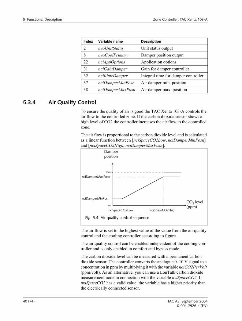
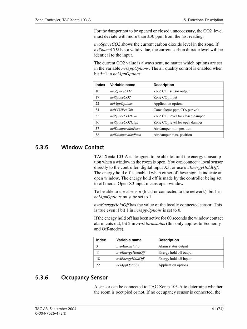
5.3.4 Air Quality Control
To ensure the quality of air is good the TAC Xenta 103-A controls the air flow to the controlled zone. If the carbon dioxide sensor shows a high level of CO2 the controller increases the air flow to the controlled zone.
The air flow is proportional to the carbon dioxide level and is calculated as a linear function between [nciSpaceCO2Low, nciDamperMinPosn] and [nciSpaceCO2High, nciDamperMaxPosn].
The air flow is set to the highest value of the value from the air quality control and the cooling controller according to figure.
The air quality control can be enabled independent of the cooling con-troller and is only enabled in comfort and bypass mode.
The carbon dioxide level can be measured with a permanent carbon dioxide sensor. The controller converts the analogue 010 V signal to a concentration in ppm by multiplying it with the variable nciCO2PerVolt (ppm/volt). As an alternative, you can use a LonTalk carbon dioxide measurement node in connection with the variable nviSpaceCO2. If nviSpaceCO2 has a valid value, the variable has a higher priority than the electrically connected sensor.
Index Variable name Description
2 nvoUnitStatus Unit status output8 nvoCoolPrimary Damper position output22 nciAppOptions Application options31 nciGainDamper Gain for damper controller32 nciItimeDamper Integral time for damper controller37 nciDamperMinPosn Air damper min. position38 nciDamperMaxPosn Air damper max. position
100%
0%
Damperposition
CO2 level(ppm)
Fig. 5.4: Air quality control sequence
nciDamperMaxPosn
nciDamperMinPosn
nciSpaceCO2Low nciSpaceCO2High
40 (74) TAC AB, September 20040-004-7526-4 (EN)
Zone Controller, TAC Xenta 103-A 5 Functional Description
For the damper not to be opened or closed unneccessary, the CO2 level must deviate with more than ±30 ppm from the last reading.
nvoSpaceCO2 shows the current carbon dioxide level in the zone. If nviSpaceCO2 has a valid value, the current carbon dioxide level will be identical to the input.
The current CO2 value is always sent, no matter which options are set in the variable nciAppOptions. The air quality control is enabled when bit 5=1 in nciAppOptions.
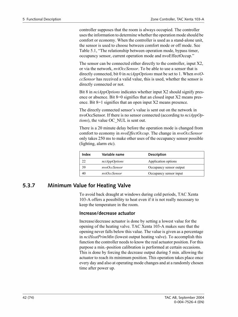
5.3.5 Window Contact
TAC Xenta 103-A is designed to be able to limit the energy consump-tion when a window in the room is open. You can connect a local sensor directly to the controller, digital input X3, or use nviEnergyHoldOff. The energy hold off is enabled when either of these signals indicate an open window. The energy hold off is made by the controller being set to off mode. Open X3 input means open window.
To be able to use a sensor (local or connected to the network), bit 1 in nciAppOptions must be set to 1.
nvoEnergyHoldOff has the value of the locally connected sensor. This is true even if bit 1 in nciAppOptions is set to 0.
If the energy hold off has been active for 60 seconds the window contact alarm cuts out, bit 2 in nvoAlarmstatus (this only applies to Economy and Off-modes).
5.3.6 Occupancy Sensor
A sensor can be connected to TAC Xenta 103-A to determine whether the room is occupied or not. If no occupancy sensor is connected, the
Index Variable name Description
10 nvoSpaceCO2 Zone CO2 sensor output
17 nviSpaceCO2 Zone CO2 input
22 nciAppOptions Application options
34 nciCO2PerVolt Conv. factor ppm CO2 per volt
35 nciSpaceCO2Low Zone CO2 level for closed damper
36 nciSpaceCO2High Zone CO2 level for open damper
37 nciDamperMinPosn Air damper min. position
38 nciDamperMaxPosn Air damper max. position
Index Variable name Description
3 nvoAlarmstatus Alarm status output
11 nvoEnergyHoldOff Energy hold off output
18 nviEnergyHoldOff Energy hold off input
22 nciAppOptions Application options
TAC AB, September 2004 41 (74)0-004-7526-4 (EN)
5 Functional Description Zone Controller, TAC Xenta 103-A
controller supposes that the room is always occupied. The controller uses the information to determine whether the operation mode should be comfort or economy. When the controller is used as a stand-alone unit, the sensor is used to choose between comfort mode or off mode. See Table 5.1, The relationship between operation mode, bypass timer, occupancy sensor, current operation mode and nvoEffectOccup.
The sensor can be connected either directly to the controller, input X2, or via the network, nviOccSensor. To be able to use a sensor that is directly connected, bit 0 in nciAppOptions must be set to 1. When nviO-ccSensor has received a valid value, this is used, whether the sensor is directly connected or not.
Bit 8 in nciAppOptions indicates whether input X2 should signify pres-ence or absence. Bit 8=0 signifies that an closed input X2 means pres-ence. Bit 8=1 signifies that an open input X2 means presence.
The directly connected sensors value is sent out on the network in nvoOccSensor. If there is no sensor connected (according to nciAppOp-tions), the value OC_NUL is sent out.
There is a 20 minute delay before the operation mode is changed from comfort to economy in nvoEffectOccup. The change in nvoOccSensor only takes 250 ms to make other uses of the occupancy sensor possible (lighting, alarm etc).
5.3.7 Minimum Value for Heating Valve
To avoid back draught at windows during cold periods, TAC Xenta 103-A offers a possibility to heat even if it is not really necessary to keep the temperature in the room.
Increase/decrease actuator
Increase/decrease actuator is done by setting a lowest value for the opening of the heating valve. TAC Xenta 103-A makes sure that the opening never falls below this value. The value is given as a percentage in nciHeatPrimMin (lowest output heating valve). To accomplish this function the controller needs to know the real actuator position. For this purpose a min.-position calibration is performed at certain occasions. This is done by forcing the decrease output during 5 min. allowing the actuator to reach its minimum position. This operation takes place once every day and also at operating mode changes and at a randomly chosen time after power up.
Index Variable name Description
22 nciAppOptions Application options
39 nvoOccSensor Occupancy sensor output
40 nviOccSensor Occupancy sensor input
42 (74) TAC AB, September 20040-004-7526-4 (EN)
Zone Controller, TAC Xenta 103-A 5 Functional Description
Thermo-actuator
The percentage in nciHeatPrimMin is recalculated to a degree number. This degree number is used to simulate a lower room temperature than the usual and thus get additional heating.
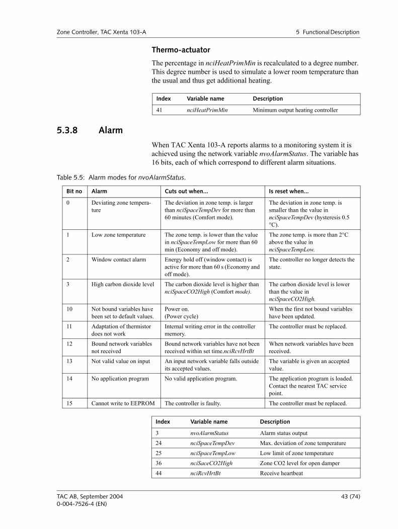
5.3.8 Alarm
When TAC Xenta 103-A reports alarms to a monitoring system it is achieved using the network variable nvoAlarmStatus. The variable has 16 bits, each of which correspond to different alarm situations.
Index Variable name Description
41 nciHeatPrimMin Minimum output heating controller
Table 5.5: Alarm modes for nvoAlarmStatus.
Bit no Alarm Cuts out when... Is reset when...
0 Deviating zone tempera-ture
The deviation in zone temp. is larger than nciSpaceTempDev for more than 60 minutes (Comfort mode).
The deviation in zone temp. is smaller than the value in nciSpaceTempDev (hysteresis 0.5 °C).
1 Low zone temperature The zone temp. is lower than the value in nciSpaceTempLow for more than 60 min (Economy and off mode).
The zone temp. is more than 2°C above the value in nciSpaceTempLow.
2 Window contact alarm Energy hold off (window contact) is active for more than 60 s (Economy and off mode).
The controller no longer detects the state.
3 High carbon dioxide level The carbon dioxide level is higher than nciSpaceCO2High (Comfort mode).
The carbon dioxide level is lower than the value in nciSpaceCO2High.
10 Not bound variables have been set to default values.
Power on.(Power cycle)
When the first not bound variables have been updated.
11 Adaptation of thermistor does not work
Internal writing error in the controller memory.
The controller must be replaced.
12 Bound network variables not received
Bound network variables have not been received within set time.nciRcvHrtBt
When network variables have been received.
13 Not valid value on input An input network variable falls outside its accepted values.
The variable is given an accepted value.
14 No application program No valid application program. The application program is loaded. Contact the nearest TAC service point.
15 Cannot write to EEPROM The controller is faulty. The controller must be replaced.
Index Variable name Description
3 nvoAlarmStatus Alarm status output
24 nciSpaceTempDev Max. deviation of zone temperature
25 nciSpaceTempLow Low limit of zone temperature
36 nciSaceCO2High Zone CO2 level for open damper
44 nciRcvHrtBt Receive heartbeat
TAC AB, September 2004 43 (74)0-004-7526-4 (EN)
5 Functional Description Zone Controller, TAC Xenta 103-A
5.3.9 Frost Protection
The frost protection is active in the forced mode off . If the room tem-perature falls below 10 °C, e.g. if a window is open, the heating is turned on. The heating is on until the temperature gets above 11,5 °C. The con-troller uses the setpoint 12 °C.
See Chapter 5.2.2, Forcing the Controller, on page 33 for operation mode when the frost protection is enabled.
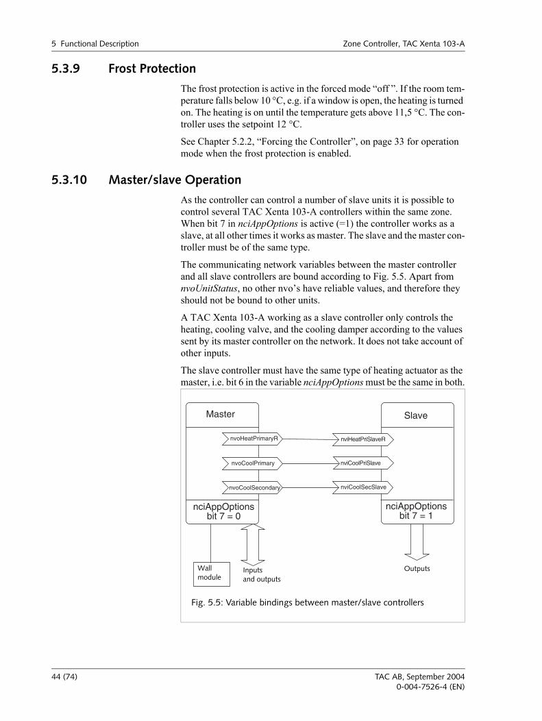
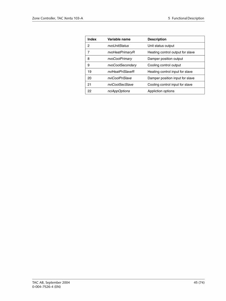
5.3.10 Master/slave Operation
As the controller can control a number of slave units it is possible to control several TAC Xenta 103-A controllers within the same zone. When bit 7 in nciAppOptions is active (=1) the controller works as a slave, at all other times it works as master. The slave and the master con-troller must be of the same type.
The communicating network variables between the master controller and all slave controllers are bound according to Fig. 5.5. Apart from nvoUnitStatus, no other nvos have reliable values, and therefore they should not be bound to other units.
A TAC Xenta 103-A working as a slave controller only controls the heating, cooling valve, and the cooling damper according to the values sent by its master controller on the network. It does not take account of other inputs.
The slave controller must have the same type of heating actuator as the master, i.e. bit 6 in the variable nciAppOptions must be the same in both.
Master
nvoCoolSecondary
nciAppOptionsbit 7 = 0
nvoCoolPrimary
nvoHeatPrimaryR nviHeatPriSlaveR
nviCoolPriSlave
nviCoolSecSlave
nciAppOptionsbit 7 = 1
Slave
Wallmodule
Inputsand outputs
Outputs
Fig. 5.5: Variable bindings between master/slave controllers
44 (74) TAC AB, September 20040-004-7526-4 (EN)
Zone Controller, TAC Xenta 103-A 5 Functional Description
Index Variable name Description
2 nvoUnitStatus Unit status output
7 nvoHeatPrimaryR Heating control output for slave
8 nvoCoolPrimary Damper position output
9 nvoCoolSecondary Cooling control output
19 nviHeatPriSlaveR Heating control input for slave
20 nviCoolPriSlave Damper position input for slave
21 nviCoolSecSlave Cooling control input for slave
22 nciAppOptions Appliction options
TAC AB, September 2004 45 (74)0-004-7526-4 (EN)
5 Functional Description Zone Controller, TAC Xenta 103-A
46 (74) TAC AB, September 20040-004-7526-4 (EN)
Zone Controller, TAC Xenta 103-A 6 Trouble-shooting
6 Trouble-shooting
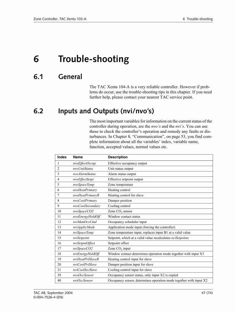
6.1 General The TAC Xenta 104-A is a very reliable controller. However if prob-lems do occur, use the trouble-shooting tips in this chapter. If you need further help, please contact your nearest TAC service point.
6.2 Inputs and Outputs (nvi/nvo’s)The most important variables for information on the current status of the controller during operation, are the nvos and the nvis. You can use these to check the controllers operation and remedy any faults or dis-turbances. In Chapter 8, Communication, on page 53, you find com-plete information about all the variables index, variable name, function, accepted values, normal values etc.
Index Name Description
1 nvoEffectOccup Effective occupancy output2 nvoUnitStatus Unit status output3 nvoAlarmStatus Alarm status output4 nvoEffectSetpt Effective setpoint output5 nvoSpaceTemp Zone temperature 6 nvoHeatPrimary Heating control 7 nvoHeatPrimaryR Heating control for slave8 nvoCoolPrimary Damper position 9 nvoCoolSecondary Cooling control 10 nvoSpaceCO2 Zone CO2 sensor11 nvoEnergyHoldOff Window contact status 12 nviManOccCmd Occupancy scheduler input 13 nviApplicMode Application mode input (forcing the controller) 14 nviSpaceTemp Zone temperature input, replaces input B1 at a valid value 15 nviSetpoint Setpoint, which at a valid value recalculates nciSetpoints 16 nviSetpntOffset Setpoint offset17 nviSpaceCO2 Zone CO2 input18 nviEnergyHoldOff Window contact determines operation mode together with input X319 nviHeatPriSlaveR Heating control input for slave20 nviCoolPriSlave Damper position input for slave 21 nviCoolSecSlave Cooling control input for slave39 nvoOccSensor Occupancy sensor status, only input X2 is copied40 nviOccSensor Occupancy sensor, determines operation mode together with input X2
TAC AB, September 2004 47 (74)0-004-7526-4 (EN)
6 Trouble-shooting Zone Controller, TAC Xenta 103-A
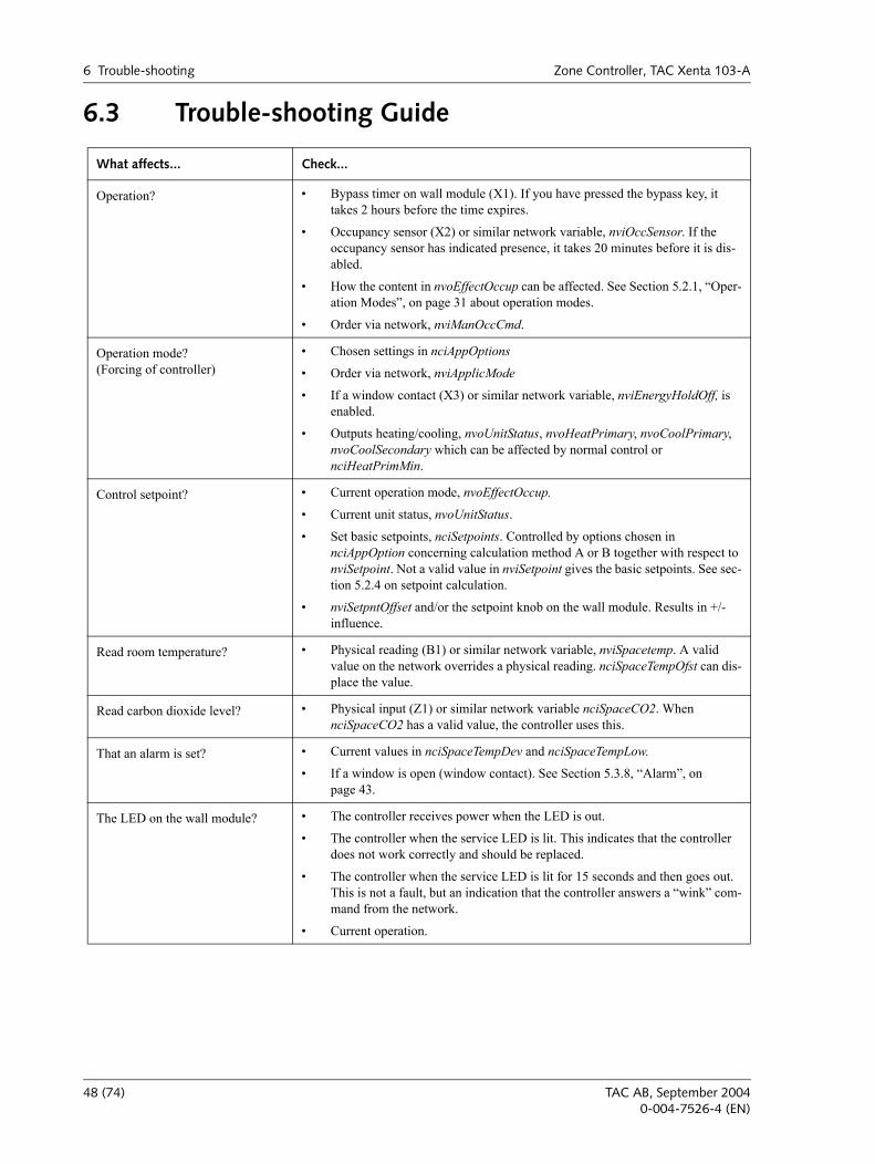
6.3 Trouble-shooting Guide
What affects... Check...
Operation? Bypass timer on wall module (X1). If you have pressed the bypass key, it takes 2 hours before the time expires.
Occupancy sensor (X2) or similar network variable, nviOccSensor. If the occupancy sensor has indicated presence, it takes 20 minutes before it is dis-abled.
How the content in nvoEffectOccup can be affected. See Section 5.2.1, Oper-ation Modes, on page 31 about operation modes.
Order via network, nviManOccCmd.
Operation mode?(Forcing of controller)
Chosen settings in nciAppOptions
Order via network, nviApplicMode
If a window contact (X3) or similar network variable, nviEnergyHoldOff, is enabled.
Outputs heating/cooling, nvoUnitStatus, nvoHeatPrimary, nvoCoolPrimary, nvoCoolSecondary which can be affected by normal control or nciHeatPrimMin.
Control setpoint? Current operation mode, nvoEffectOccup.
Current unit status, nvoUnitStatus.
Set basic setpoints, nciSetpoints. Controlled by options chosen in nciAppOption concerning calculation method A or B together with respect to nviSetpoint. Not a valid value in nviSetpoint gives the basic setpoints. See sec-tion 5.2.4 on setpoint calculation.
nviSetpntOffset and/or the setpoint knob on the wall module. Results in +/- influence.
Read room temperature? Physical reading (B1) or similar network variable, nviSpacetemp. A valid value on the network overrides a physical reading. nciSpaceTempOfst can dis-place the value.
Read carbon dioxide level? Physical input (Z1) or similar network variable nciSpaceCO2. When nciSpaceCO2 has a valid value, the controller uses this.
That an alarm is set? Current values in nciSpaceTempDev and nciSpaceTempLow.
If a window is open (window contact). See Section 5.3.8, Alarm, on page 43.
The LED on the wall module? The controller receives power when the LED is out.
The controller when the service LED is lit. This indicates that the controller does not work correctly and should be replaced.
The controller when the service LED is lit for 15 seconds and then goes out. This is not a fault, but an indication that the controller answers a wink com-mand from the network.
Current operation.
48 (74) TAC AB, September 20040-004-7526-4 (EN)
Zone Controller, TAC Xenta 103-A 7 Technical Data
7 Technical Data
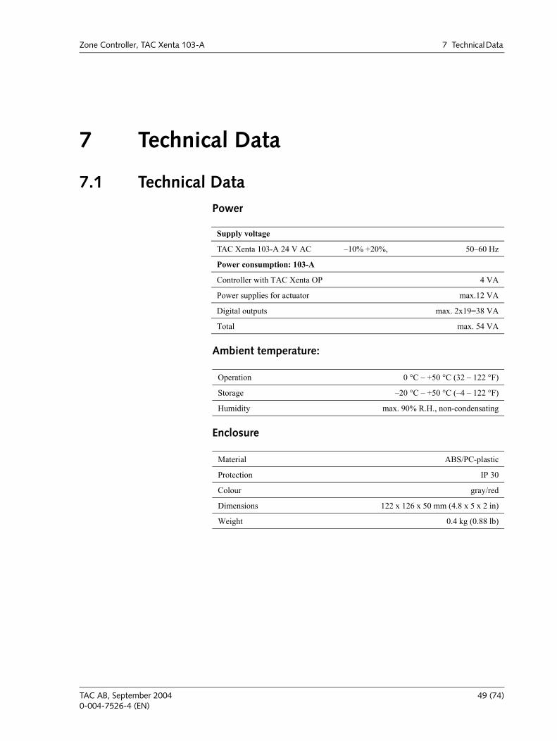
7.1 Technical DataPower
Ambient temperature:
Enclosure
Supply voltage
TAC Xenta 103-A 24 V AC 10% +20%, 5060 Hz
Power consumption: 103-A
Controller with TAC Xenta OP 4 VA
Power supplies for actuator max.12 VA
Digital outputs max. 2x19=38 VA
Total max. 54 VA
Operation 0 °C +50 °C (32 122 °F)
Storage 20 °C +50 °C (4 122 °F)
Humidity max. 90% R.H., non-condensating
Material ABS/PC-plastic
Protection IP 30
Colour gray/red
Dimensions 122 x 126 x 50 mm (4.8 x 5 x 2 in)
Weight 0.4 kg (0.88 lb)
TAC AB, September 2004 49 (74)0-004-7526-4 (EN)
7 Technical Data Zone Controller, TAC Xenta 103-A
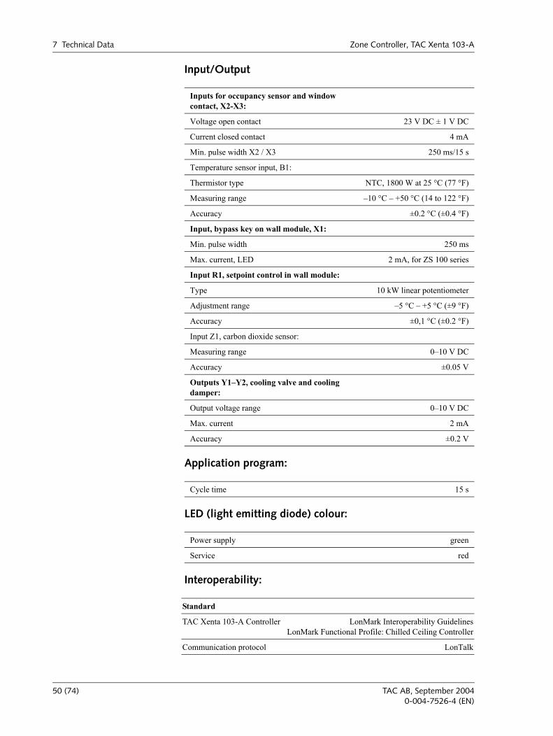
Input/Output
Application program:
LED (light emitting diode) colour:
Interoperability:
Inputs for occupancy sensor and window contact, X2-X3:
Voltage open contact 23 V DC ± 1 V DC
Current closed contact 4 mA
Min. pulse width X2 / X3 250 ms/15 s
Temperature sensor input, B1:
Thermistor type NTC, 1800 W at 25 °C (77 °F)
Measuring range 10 °C +50 °C (14 to 122 °F)
Accuracy ±0.2 °C (±0.4 °F)
Input, bypass key on wall module, X1:
Min. pulse width 250 ms
Max. current, LED 2 mA, for ZS 100 series
Input R1, setpoint control in wall module:
Type 10 kW linear potentiometer
Adjustment range 5 °C +5 °C (±9 °F)
Accuracy ±0,1 °C (±0.2 °F)
Input Z1, carbon dioxide sensor:
Measuring range 010 V DC
Accuracy ±0.05 V
Outputs Y1Y2, cooling valve and cooling damper:
Output voltage range 010 V DC
Max. current 2 mA
Accuracy ±0.2 V
Cycle time 15 s
Power supply green
Service red
Standard
TAC Xenta 103-A Controller LonMark Interoperability GuidelinesLonMark Functional Profile: Chilled Ceiling Controller
Communication protocol LonTalk
50 (74) TAC AB, September 20040-004-7526-4 (EN)
Zone Controller, TAC Xenta 103-A 7 Technical Data
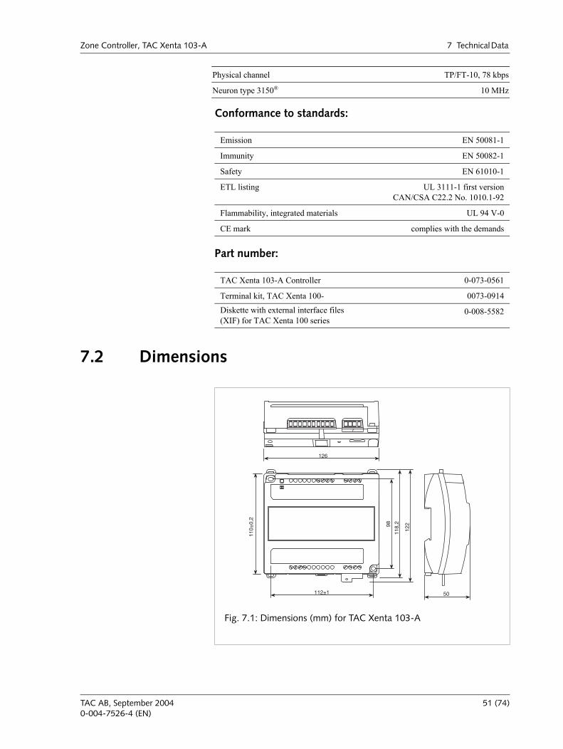
Conformance to standards:
Part number:
7.2 Dimensions
Physical channel TP/FT-10, 78 kbps
Neuron type 3150® 10 MHz
Emission EN 50081-1
Immunity EN 50082-1
Safety EN 61010-1
ETL listing UL 3111-1 first versionCAN/CSA C22.2 No. 1010.1-92
Flammability, integrated materials UL 94 V-0
CE mark complies with the demands
TAC Xenta 103-A Controller 0-073-0561
Terminal kit, TAC Xenta 100- 0073-0914
Diskette with external interface files (XIF) for TAC Xenta 100 series
0-008-5582
126
110±
0,2
112±1
98
118,
2
122
50
Fig. 7.1: Dimensions (mm) for TAC Xenta 103-A
TAC AB, September 2004 51 (74)0-004-7526-4 (EN)
7 Technical Data Zone Controller, TAC Xenta 103-A
52 (74) TAC AB, September 20040-004-7526-4 (EN)
Zone Controller, TAC Xenta 103-A 8 Communication
8 Communication
8.1 General The controller consists of two LonMark objects: the node object (Chapter 8.5, The Node Object, on page 55) and the controller object (Chapter 8.6, The Controller Object, on page 56). These objects are monitored using the network variables nviRequest and nvoStatus.
The network variable nciLocation is used when configuring the basic parameters (Chapter 4.1, Basic Parameters, on page 26) to give a detailed description of the actual place where the controller is fitted. The variable receives an arbitrary string of signs and dividers as long as the string is no longer than 30 signs. You can program a specific location label, e.g.
TAMF.main.floor3.room343/RC40
A LNS based network management tool uses nciLocation when a data base needs to be recreated. The monitoring of an installed network is made by the LNS tool reading nciLocation, and then using the informa-tion to give the node a subsystem name and a unit name. The string should therefore consist of a name and a search path for the subsystem, followed by a slash and the unit name, i.e.
system.subsystem[.subsystem...]/unit name
8.2 Default Settings and Power on For all network variables the following settings are valid:
Number of sent messages per time unit: NONE
Service type: NOT CONFIRMED if not stated otherwise
Access check: NO, possible to configure: YES.
Polled: NO for all nvo and nci, YES for all nvi (starting up)
Synchronized: NO
Change/update only when the controller is not active on the net-work; flags = NO
Restart of TAC Xenta 103-A after change; flags = YES
All network variables have the same index as they have in the menu tree in the operator panel TAC Xenta OP. They represent the order in which
TAC AB, September 2004 53 (74)0-004-7526-4 (EN)
8 Communication Zone Controller, TAC Xenta 103-A
they have been declared in the system program; as the order is important for the variables self documentatory string. The variables are of a stan-dard type or so called SNVT. The values that each SNVT can receive, are listed in the tables in this chapter. Apart from SNVT, there are also standard configuration parameters (SCPT) and parameter types for user configuration (UCPT). To learns more about SNVT/SCPT/UCPT see the The SNVT Master List and Programmer's Guide on www.lon-mark.org.
At power on, all variables for inputs and outputs (nvi and nvo) receive their default values. On a restart the configuration parameters (nci) retain their earlier set values. After restart every nvi will send a request to all the nvo to which they are bound (a poll).
8.3 Monitoring Network Variables, HeartbeatThe TAC Xenta 103-A has a function, called Heartbeat, which can be configured to monitor input and output variables on the network.
In the overviews in this chapter, you can see whether the variable is monitored with Heartbeat in the column Hb.
Inputs
Some of the inputs to the TAC Xenta 103-A are monitored in a way that the variable must receive values within a certain time for it to be regarded as valid. If no value is received within this time, the variable will return to its default value. An alarm will also is enabled, bit 12 in nvoAlarmStatus.
Which inputs are monitored in this way, you find in the list of network variables in Chapter 8.6.1, The Controller Objects Inputs (nvi), on page 59.
The time is set with the variable nciRcvHrtBt. Its default value is 0.0, which means that no monitoring is performed.
Outputs
The bound outputs are normally sent out when they are changed. Most outputs of the TAC Xenta 103-A are monitored, so even if the values are not changed, they are sent out at even intervals.
Which outputs are monitored in this way, you find in the list of network variables in Chapter 8.6.2, The Controller Objects Outputs (nvo), on page 60.
The time is set with the variable nciSndHrtBt. Its normal value is 0.0, which means that no monitoring is performed.
54 (74) TAC AB, September 20040-004-7526-4 (EN)
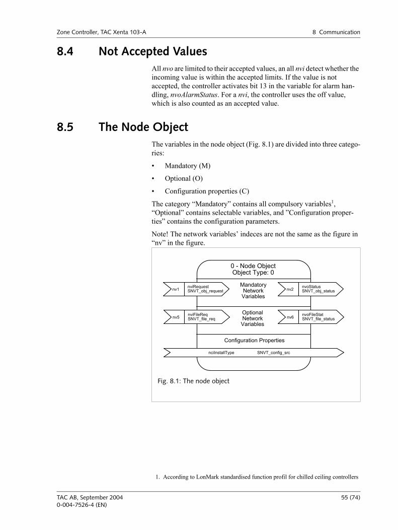
Zone Controller, TAC Xenta 103-A 8 Communication
8.4 Not Accepted ValuesAll nvo are limited to their accepted values, an all nvi detect whether the incoming value is within the accepted limits. If the value is not accepted, the controller activates bit 13 in the variable for alarm han-dling, nvoAlarmStatus. For a nvi, the controller uses the off value, which is also counted as an accepted value.
8.5 The Node ObjectThe variables in the node object (Fig. 8.1) are divided into three catego-ries:
Mandatory (M)
Optional (O)
Configuration properties (C)
The category Mandatory contains all compulsory variables1, Optional contains selectable variables, and Configuration proper-ties contains the configuration parameters.
Note! The network variables indeces are not the same as the figure in nv in the figure.
1. According to LonMark standardised function profil for chilled ceiling controllers
nviRequestSNVT_obj_request
nvoStatusSNVT_obj_status
nviFileReqSNVT_file_req
nvoFileStatSNVT_file_status
nv1 nv2
nv5 nv6
Configuration Properties
nciInstallType SNVT_config_src
OptionalNetworkVariables
MandatoryNetworkVariables
0 - Node ObjectObject Type: 0
Fig. 8.1: The node object
TAC AB, September 2004 55 (74)0-004-7526-4 (EN)
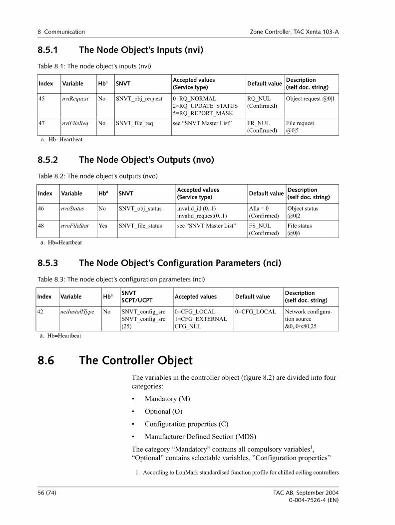
8 Communication Zone Controller, TAC Xenta 103-A
8.5.1 The Node Object’s Inputs (nvi)
8.5.2 The Node Object’s Outputs (nvo)
8.5.3 The Node Object’s Configuration Parameters (nci)
8.6 The Controller ObjectThe variables in the controller object (figure 8.2) are divided into four categories:
Mandatory (M)
Optional (O)
Configuration properties (C)
Manufacturer Defined Section (MDS)
The category Mandatory contains all compulsory variables1, Optional contains selectable variables, Configuration properties
Table 8.1: The node object’s inputs (nvi)
Index Variable Hba
a. Hb=Heartbeat
SNVTAccepted values (Service type)
Default valueDescription(self doc. string)
45 nviRequest No SNVT_obj_request 0=RQ_NORMAL2=RQ_UPDATE_STATUS5=RQ_REPORT_MASK
RQ_NUL (Confirmed)
Object request @0|1
47 nviFileReq No SNVT_file_req see SNVT Master List FR_NUL (Confirmed)
File request@0|5
Table 8.2: The node object’s outputs (nvo)
Index Variable Hba
a. Hb=Heartbeat
SNVTAccepted values(Service type)
Default valueDescription(self doc. string)
46 nvoStatus No SNVT_obj_status invalid_id (0..1)invalid_request(0..1)
Alla = 0(Confirmed)
Object status@0|2
48 nvoFileStat Yes SNVT_file_status see SNVT Master List FS_NUL(Confirmed)
File status@0|6
Table 8.3: The node object’s configuration parameters (nci)
Index Variable Hba
a. Hb=Heartbeat
SNVTSCPT/UCPT
Accepted values Default valueDescription(self doc. string)
42 nciInstallType No SNVT_config_srcSNVT_config_src(25)
0=CFG_LOCAL1=CFG_EXTERNALCFG_NUL
0=CFG_LOCAL Network configura-tion source &0,,0\x80,25
1. According to LonMark standardised function profile for chilled ceiling controllers
56 (74) TAC AB, September 20040-004-7526-4 (EN)
Zone Controller, TAC Xenta 103-A 8 Communication
contains configuration parameters, and Manufacturer Defined Sec-tion includes all other variables that make the controllers functions possible.
TAC AB, September 2004 57 (74)0-004-7526-4 (EN)
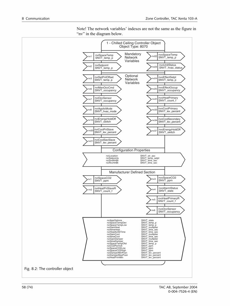
8 Communication Zone Controller, TAC Xenta 103-A
Note! The network variables indexes are not the same as the figure in nv in the diagram below.
nv1
nv2
nv22
nv23
nv6
nviSpaceTempSNVT_temp_p
nviSetpointSNVT_temp_p
nviManOccCmdSNVT_occupancy
nvoSpaceTempSNVT_temp_p
nvoUnitStatusSNVT_hvac_status
nciLocation SNVT_str_ascnciSetpoints SNVT_temp_setptnciSndHrtBt SNVT_time_secnciRcvHrtBt SNVT_time_sec
Configuration Properties
Manufacturer Defined Section
MandatoryNetworkVariables
OptionalNetworkVariables
1 - Chilled Ceiling Controller ObjectObject Type: 8070
nv3 nviSetPntOffsetSNVT_temp_p
nv1 nviSpaceCO2SNVT_ppm
nv2 nviHeatPriSlaveRSNVT_count_f
nv20 nviCoolPriSlaveSNVT_lev_percent
nv21 nviCoolSecSlaveSNVT_lev_percent
nv24 nvoEffectSetptSNVT_temp_p
nv25 nvoEffectOccupSNVT_occupancy
nv33 nvoCoolPrimarySNVT_lev_percent
nv31 nvoHeatPrimarySNVT_count_f
nv3 nvoSpaceCO2SNVT_ppm
nv34 nvoCoolSecondarySNVT_lev_percent
nv37 nvoEnergyHoldOffSNVT_switch
nv4 nvoAlarmStatusSNVT_state
nv7 nviOccSensorSNVT_occupancy
nv10 nviEnergyHoldOffSNVT_switch
nv8 nviApplicModeSNVT_hvac_mode
nciAppOptions SNVT_statenciSpaceTempDev SNVT_temp_pnciSpaceTempLow SNVT_temp_pnciGainHeat SNVT_multipliernciItimeHeat SNVT_time_secnciHeatActStTime SNVT_time_secnciGainCool SNVT_multipliernciItimeCool SNVT_time_secnciGainDamper SNVT_multipliernciItimeDamper SNVT_time_secnciSpaceTempOfst SNVT_temp_pnciCO2PerVolt SNVT_ppmnciSpaceCO2Low SNVT_ppmnciSpaceCO2High SNVT_ppmnciDamperMinPosn SNVT_lev_percentnciDamperMaxPosn SNVT_lev_percentnciHeatPrimMin SNVT_lev_percent
nv6 nvoOccSensorSNVT_occupancy
nv5 nvoHeatPrimaryRSNVT_count_f
Fig. 8.2: The controller object
58 (74) TAC AB, September 20040-004-7526-4 (EN)
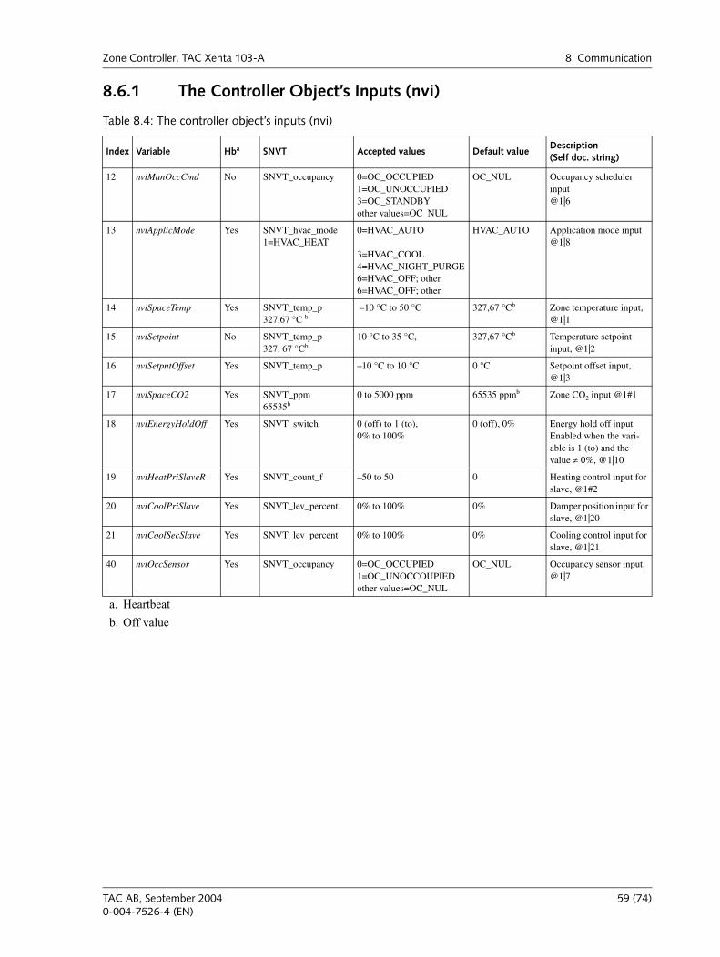
Zone Controller, TAC Xenta 103-A 8 Communication
8.6.1 The Controller Object’s Inputs (nvi)
Table 8.4: The controller object’s inputs (nvi)
Index Variable Hba
a. Heartbeat
SNVT Accepted values Default valueDescription(Self doc. string)
12 nviManOccCmd No SNVT_occupancy 0=OC_OCCUPIED1=OC_UNOCCUPIED3=OC_STANDBYother values=OC_NUL
OC_NUL Occupancy scheduler input@1|6
13 nviApplicMode Yes SNVT_hvac_mode1=HVAC_HEAT
0=HVAC_AUTO
3=HVAC_COOL4=HVAC_NIGHT_PURGE6=HVAC_OFF; other 6=HVAC_OFF; other
HVAC_AUTO Application mode input@1|8
14 nviSpaceTemp Yes SNVT_temp_p327,67 °C b
b. Off value
–10 °C to 50 °C 327,67 °Cb Zone temperature input, @1|1
15 nviSetpoint No SNVT_temp_p327, 67 °Cb
10 °C to 35 °C, 327,67 °Cb Temperature setpoint input, @1|2
16 nviSetpntOffset Yes SNVT_temp_p –10 °C to 10 °C 0 °C Setpoint offset input, @1|3
17 nviSpaceCO2 Yes SNVT_ppm65535b
0 to 5000 ppm 65535 ppmb Zone CO2 input @1#1
18 nviEnergyHoldOff Yes SNVT_switch 0 (off) to 1 (to),0% to 100%
0 (off), 0% Energy hold off input Enabled when the vari-able is 1 (to) and the value ≠ 0%, @1|10
19 nviHeatPriSlaveR Yes SNVT_count_f –50 to 50 0 Heating control input for slave, @1#2
20 nviCoolPriSlave Yes SNVT_lev_percent 0% to 100% 0% Damper position input for slave, @1|20
21 nviCoolSecSlave Yes SNVT_lev_percent 0% to 100% 0% Cooling control input for slave, @1|21
40 nviOccSensor Yes SNVT_occupancy 0=OC_OCCUPIED1=OC_UNOCCOUPIEDother values=OC_NUL
OC_NUL Occupancy sensor input, @1|7
TAC AB, September 2004 59 (74)0-004-7526-4 (EN)
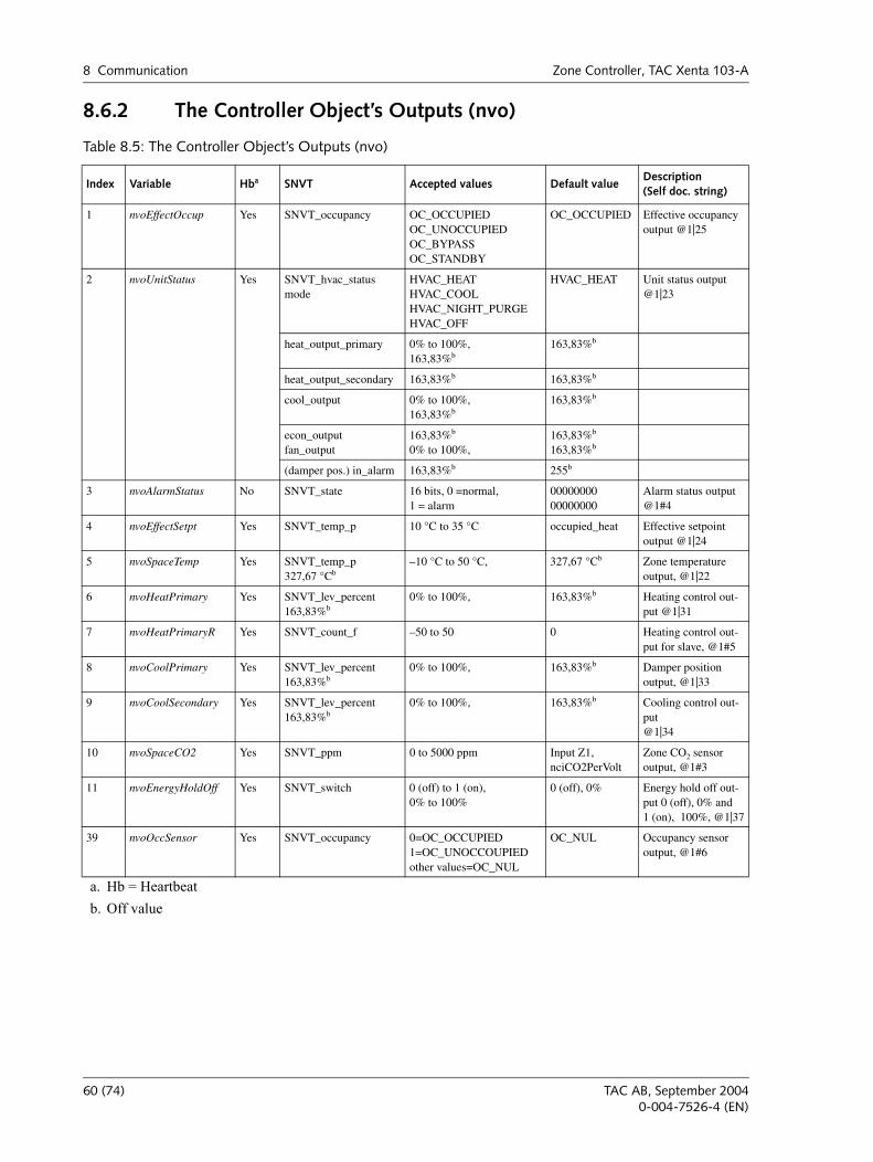
8 Communication Zone Controller, TAC Xenta 103-A
8.6.2 The Controller Object’s Outputs (nvo)
Table 8.5: The Controller Object’s Outputs (nvo)
Index Variable Hba
a. Hb = Heartbeat
SNVT Accepted values Default valueDescription(Self doc. string)
1 nvoEffectOccup Yes SNVT_occupancy OC_OCCUPIEDOC_UNOCCUPIEDOC_BYPASSOC_STANDBY
OC_OCCUPIED Effective occupancy output @1|25
2 nvoUnitStatus Yes SNVT_hvac_statusmode
HVAC_HEATHVAC_COOLHVAC_NIGHT_PURGEHVAC_OFF
HVAC_HEAT Unit status output @1|23
heat_output_primary 0% to 100%,163,83%b
163,83%b
heat_output_secondary 163,83%b 163,83%b
cool_output 0% to 100%,163,83%b
163,83%b
econ_outputfan_output
163,83%b
0% to 100%,163,83%b
163,83%b
(damper pos.) in_alarm 163,83%b 255b
3 nvoAlarmStatus No SNVT_state 16 bits, 0 =normal,1 = alarm
0000000000000000
Alarm status output@1#4
4 nvoEffectSetpt Yes SNVT_temp_p 10 °C to 35 °C occupied_heat Effective setpoint output @1|24
5 nvoSpaceTemp Yes SNVT_temp_p327,67 °Cb
b. Off value
–10 °C to 50 °C, 327,67 °Cb Zone temperature output, @1|22
6 nvoHeatPrimary Yes SNVT_lev_percent163,83%b
0% to 100%, 163,83%b Heating control out-put @1|31
7 nvoHeatPrimaryR Yes SNVT_count_f –50 to 50 0 Heating control out-put for slave, @1#5
8 nvoCoolPrimary Yes SNVT_lev_percent163,83%b
0% to 100%, 163,83%b Damper position output, @1|33
9 nvoCoolSecondary Yes SNVT_lev_percent 163,83%b
0% to 100%, 163,83%b Cooling control out-put@1|34
10 nvoSpaceCO2 Yes SNVT_ppm 0 to 5000 ppm Input Z1,nciCO2PerVolt
Zone CO2 sensor output, @1#3
11 nvoEnergyHoldOff Yes SNVT_switch 0 (off) to 1 (on),0% to 100%
0 (off), 0% Energy hold off out-put 0 (off), 0% and 1 (on), 100%, @1|37
39 nvoOccSensor Yes SNVT_occupancy 0=OC_OCCUPIED1=OC_UNOCCOUPIEDother values=OC_NUL
OC_NUL Occupancy sensor output, @1#6
60 (74) TAC AB, September 20040-004-7526-4 (EN)
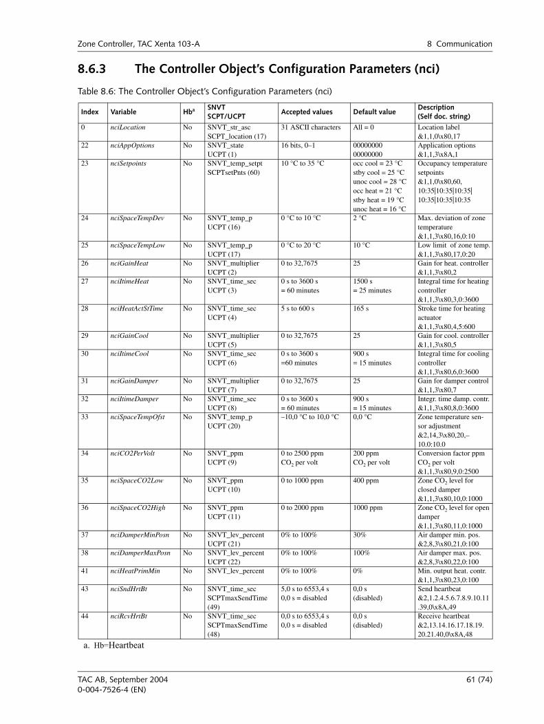
Zone Controller, TAC Xenta 103-A 8 Communication
8.6.3 The Controller Object’s Configuration Parameters (nci)
Table 8.6: The Controller Object’s Configuration Parameters (nci)
Index Variable Hba
a. Hb=Heartbeat
SNVTSCPT/UCPT
Accepted values Default valueDescription (Self doc. string)
0 nciLocation No SNVT_str_ascSCPT_location (17)
31 ASCII characters All = 0 Location label&1,1,0\x80,17
22 nciAppOptions No SNVT_stateUCPT (1)
16 bits, 0–1 0000000000000000
Application options&1,1,3\x8A,1
23 nciSetpoints No SNVT_temp_setptSCPTsetPnts (60)
10 °C to 35 °C occ cool = 23 °Cstby cool = 25 °Cunoc cool = 28 °Cocc heat = 21 °Cstby heat = 19 °Cunoc heat = 16 °C
Occupancy temperature setpoints&1,1,0\x80,60,10:35|10:35|10:35|10:35|10:35|10:35
24 nciSpaceTempDev No SNVT_temp_pUCPT (16)
0 °C to 10 °C 2 °C Max. deviation of zone temperature&1,1,3\x80,16,0:10
25 nciSpaceTempLow No SNVT_temp_pUCPT (17)
0 °C to 20 °C 10 °C Low limit of zone temp.&1,1,3\x80,17,0:20
26 nciGainHeat No SNVT_multiplierUCPT (2)
0 to 32,7675 25 Gain for heat. controller &1,1,3\x80,2
27 nciItimeHeat No SNVT_time_secUCPT (3)
0 s to 3600 s= 60 minutes
1500 s= 25 minutes
Integral time for heating controller&1,1,3\x80,3,0:3600
28 nciHeatActStTime No SNVT_time_secUCPT (4)
5 s to 600 s 165 s Stroke time for heating actuator &1,1,3\x80,4,5:600
29 nciGainCool No SNVT_multiplierUCPT (5)
0 to 32,7675 25 Gain for cool. controller &1,1,3\x80,5
30 nciItimeCool No SNVT_time_secUCPT (6)
0 s to 3600 s=60 minutes
900 s= 15 minutes
Integral time for cooling controller&1,1,3\x80,6,0:3600
31 nciGainDamper No SNVT_multiplierUCPT (7)
0 to 32,7675 25 Gain for damper control &1,1,3\x80,7
32 nciItimeDamper No SNVT_time_secUCPT (8)
0 s to 3600 s= 60 minutes
900 s= 15 minutes
Integr. time damp. contr.&1,1,3\x80,8,0:3600
33 nciSpaceTempOfst No SNVT_temp_pUCPT (20)
–10,0 °C to 10,0 °C 0,0 °C Zone temperature sen-sor adjustment &2,14,3\x80,20,–10.0:10.0
34 nciCO2PerVolt No SNVT_ppmUCPT (9)
0 to 2500 ppmCO2 per volt
200 ppmCO2 per volt
Conversion factor ppm CO2 per volt&1,1,3\x80,9,0:2500
35 nciSpaceCO2Low No SNVT_ppmUCPT (10)
0 to 1000 ppm 400 ppm Zone CO2 level for closed damper&1,1,3\x80,10,0:1000
36 nciSpaceCO2High No SNVT_ppmUCPT (11)
0 to 2000 ppm 1000 ppm Zone CO2 level for open damper&1,1,3\x80,11,0:1000
37 nciDamperMinPosn No SNVT_lev_percentUCPT (21)
0% to 100% 30% Air damper min. pos.&2,8,3\x80,21,0:100
38 nciDamperMaxPosn No SNVT_lev_percentUCPT (22)
0% to 100% 100% Air damper max. pos.&2,8,3\x80,22,0:100
41 nciHeatPrimMin No SNVT_lev_percent 0% to 100% 0% Min. output heat. contr.&1,1,3\x80,23,0:100
43 nciSndHrtBt No SNVT_time_secSCPTmaxSendTime (49)
5,0 s to 6553,4 s0,0 s = disabled
0,0 s(disabled)
Send heartbeat&2,1.2.4.5.6.7.8.9.10.11.39,0\x8A,49
44 nciRcvHrtBt No SNVT_time_secSCPTmaxSendTime (48)
0,0 s to 6553,4 s0,0 s = disabled
0,0 s(disabled)
Receive heartbeat&2,13.14.16.17.18.19. 20.21.40,0\x8A,48
TAC AB, September 2004 61 (74)0-004-7526-4 (EN)

8 Communication Zone Controller, TAC Xenta 103-A
62 (74) TAC AB, September 20040-004-7526-4 (EN)
APPENDIX
A Setpoint Calculation

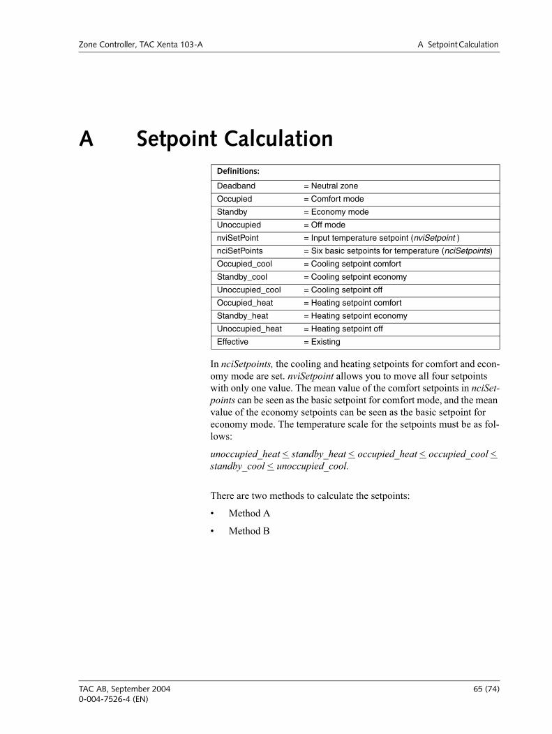
Zone Controller, TAC Xenta 103-A A Setpoint Calculation
A Setpoint Calculation
In nciSetpoints, the cooling and heating setpoints for comfort and econ-omy mode are set. nviSetpoint allows you to move all four setpoints with only one value. The mean value of the comfort setpoints in nciSet-points can be seen as the basic setpoint for comfort mode, and the mean value of the economy setpoints can be seen as the basic setpoint for economy mode. The temperature scale for the setpoints must be as fol-lows:
unoccupied_heat < standby_heat < occupied_heat < occupied_cool < standby_cool < unoccupied_cool.
There are two methods to calculate the setpoints:
Method A
Method B
Definitions:
Deadband = Neutral zone
Occupied = Comfort mode
Standby = Economy mode
Unoccupied = Off mode
nviSetPoint = Input temperature setpoint (nviSetpoint )
nciSetPoints = Six basic setpoints for temperature (nciSetpoints)
Occupied_cool = Cooling setpoint comfort
Standby_cool = Cooling setpoint economy
Unoccupied_cool = Cooling setpoint off
Occupied_heat = Heating setpoint comfort
Standby_heat = Heating setpoint economy
Unoccupied_heat = Heating setpoint off
Effective = Existing
TAC AB, September 2004 65 (74)0-004-7526-4 (EN)
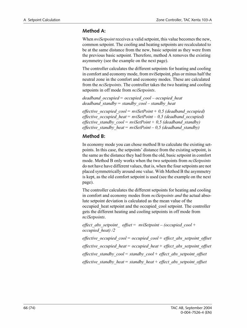
A Setpoint Calculation Zone Controller, TAC Xenta 103-A
Method A:
When nviSetpoint receives a valid setpoint, this value becomes the new, common setpoint. The cooling and heating setpoints are recalculated to be at the same distance from the new, basic setpoint as they were from the previous basic setpoint. Therefore, method A removes the existing asymmetry (see the example on the next page).
The controller calculates the different setpoints for heating and cooling in comfort and economy mode, from nviSetpoint, plus or minus half the neutral zone in the comfort and economy modes. These are calculated from the nciSetpoints. The controller takes the two heating and cooling setpoints in off mode from nciSetpoints.
deadband_occupied = occupied_cool occupied_heatdeadband_standby = standby_cool standby_heat
effective_occupied_cool = nviSetPoint + 0,5 (deadband_occupied)effective_occupied_heat = nviSetPoint 0,5 (deadband_occupied)effective_standby_cool = nviSetPoint + 0,5 (deadband_standby)effective_standby_heat = nviSetPoint 0,5 (deadband_standby)
Method B:
In economy mode you can chose method B to calculate the existing set-points. In this case, the setpoints distance from the existing setpoint, is the same as the distance they had from the old, basic setpoint in comfort mode. Method B only works when the two setpoints from nciSetpoints do not have have different values, that is, when the four setpoints are not placed symmetrically around one value. With Method B the asymmetry is kept, as the old comfort setpoint is used (see the example on the next page).
The controller calculates the different setpoints for heating and cooling in comfort and economy modes from nciSetpoints and the actual abso-lute setpoint deviation is calculated as the mean value of the occupied_heat setpoint and the occupied_cool setpoint. The controller gets the different heating and cooling setpoints in off mode from nciSetpoints.
effect_abs_setpoint_ offset = nviSetpoint (occupied_cool + occupied_heat) /2
effective_occupied_cool = occupied_cool + effect_abs_setpoint_offset
effective_occupied_heat = occupied_heat + effect_abs_setpoint_offset
effective_standby_cool = standby_cool + effect_abs_setpoint_offset
effective_standby_heat = standby_heat + effect_abs_setpoint_offset
66 (74) TAC AB, September 20040-004-7526-4 (EN)
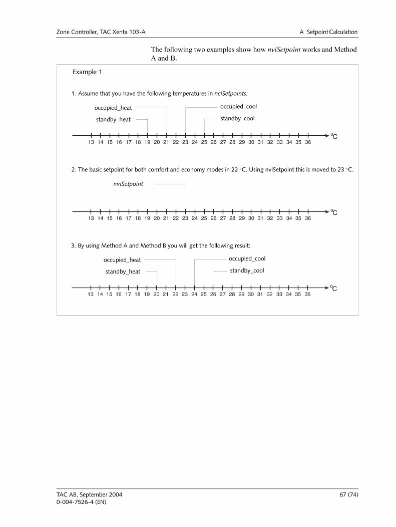
Zone Controller, TAC Xenta 103-A A Setpoint Calculation
The following two examples show how nviSetpoint works and Method A and B.
3635343332313029282726252423222120191817161514Co
13
Example 1
1. Assume that you have the following temperatures in nciSetpoints:
occupied_heat occupied_cool
standby_heat standby_cool
3635343332313029282726252423222120191817161514Co
13
2. The basic setpoint for both comfort and economy modes in 22 °C. Using nviSetpoint this is moved to 23 °C.
nviSetpoint
3635343332313029282726252423222120191817161514Co
13
3. By using Method A and Method B you will get the following result:
occupied_heat occupied_cool
standby_heat standby_cool
TAC AB, September 2004 67 (74)0-004-7526-4 (EN)
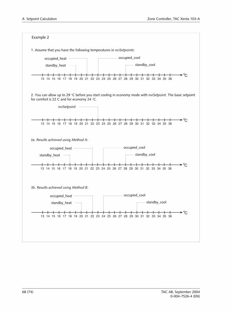
A Setpoint Calculation Zone Controller, TAC Xenta 103-A
3635343332313029282726252423222120191817161514Co
13
Example 2
1. Assume that you have the following temperatures in nciSetpoints:
occupied_heat occupied_cool
standby_heat standby_cool
3635343332313029282726252423222120191817161514Co
13
2. You can allow up to 29 °C before you start cooling in economy mode with nviSetpoint. The basic setpoint for comfort is 22 C and for economy 24 °C.
nviSetpoint
3635343332313029282726252423222120191817161514Co
13
3a. Results achieved using Method A:
occupied_heat occupied_cool
standby_heat standby_cool
3635343332313029282726252423222120191817161514Co
13
3b. Results achieved using Method B:
occupied_heat occupied_cool
standby_heat standby_cool
68 (74) TAC AB, September 20040-004-7526-4 (EN)
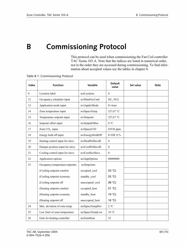
Zone Controller, TAC Xenta 103-A B Commissioning Protocol
B Commissioning ProtocolThis protocol can be used when commissioning the Fan Coil controller TAC Xenta 103-A. Note that the indices are listed in numerical order, not in the order they are accessed during commissioning. To find infor-mation about accepted values see the tables in chapter 8.
Table B.1: Commissioning Protocol
Index Function VariableDefault value
Set value Note
0 Location label nciLocation 0
12 Occupancy scheduler input nviManOccCmd OC_NUL
13 Application mode input nviApplicMode 0=Auto
14 Zone temperature input nviSpaceTemp 327,67 °C
15 Temperature setpoint input nviSetpoint 327,67 °C
16 Setpoint offset input nviSetpntOffset 0 °C
17 Zone CO2 input nviSpaceCO2 65536 ppm
18 Energy hold off input nviEnergyHoldOff 0=Off, 0 %
19 Heating control input for slave nviHeatPriSlaveR 0
20 Damper position input for slave nviCoolPriSlaveR 0
21 Cooling control input for slave nviCoolSecSlave 0
22 Application options nciAppOptions 00000000
23 Occupancy temperature setpoints nciSetpoints
(Cooling setpoint comfort occupied_cool 23 °C)
(Cooling setpoint economy standby_cool 25 °C)
(Cooling setpoint off unoccupied_cool 28 °C)
(Heating setpoint comfort occupied_heat 21 °C)
(Heating setpoint economy standby_heat 19 °C)
(Heating setpoint off unoccupied_heat 16 °C)
24 Max. deviation of zone temp. nciSpaceTempDev 2 °C
25 Low limit of zone temperature nciSpaceTempLow 10 °C
26 Gain for heating controller nciGainHeat 25
TAC AB, September 2004 69 (74)0-004-7526-4 (EN)
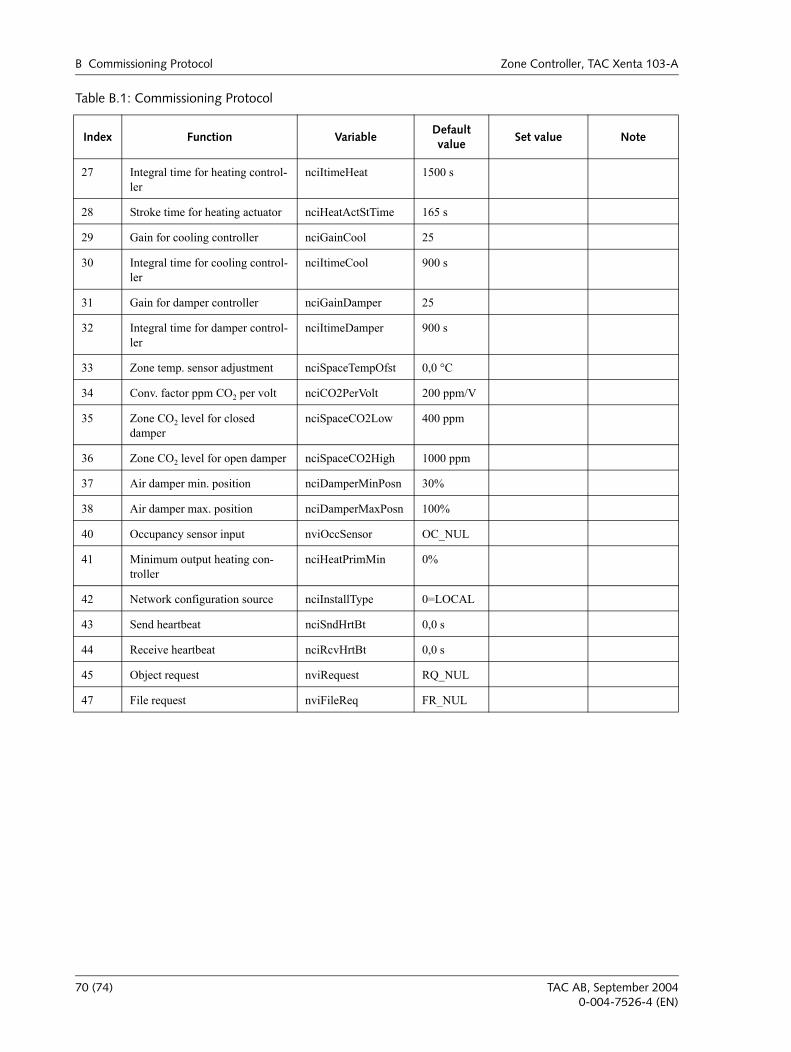
B Commissioning Protocol Zone Controller, TAC Xenta 103-A
27 Integral time for heating control-ler
nciItimeHeat 1500 s
28 Stroke time for heating actuator nciHeatActStTime 165 s
29 Gain for cooling controller nciGainCool 25
30 Integral time for cooling control-ler
nciItimeCool 900 s
31 Gain for damper controller nciGainDamper 25
32 Integral time for damper control-ler
nciItimeDamper 900 s
33 Zone temp. sensor adjustment nciSpaceTempOfst 0,0 °C
34 Conv. factor ppm CO2 per volt nciCO2PerVolt 200 ppm/V
35 Zone CO2 level for closed damper
nciSpaceCO2Low 400 ppm
36 Zone CO2 level for open damper nciSpaceCO2High 1000 ppm
37 Air damper min. position nciDamperMinPosn 30%
38 Air damper max. position nciDamperMaxPosn 100%
40 Occupancy sensor input nviOccSensor OC_NUL
41 Minimum output heating con-troller
nciHeatPrimMin 0%
42 Network configuration source nciInstallType 0=LOCAL
43 Send heartbeat nciSndHrtBt 0,0 s
44 Receive heartbeat nciRcvHrtBt 0,0 s
45 Object request nviRequest RQ_NUL
47 File request nviFileReq FR_NUL
Table B.1: Commissioning Protocol
Index Function VariableDefault value
Set value Note
70 (74) TAC AB, September 20040-004-7526-4 (EN)
Zone Controller, TAC Xenta 103-A Index
IndexAalarm 43application 15
Bbasic parameters 26bypass mode 33
Ccables 19calculation 35comfort mode 32commissioning 22commissioning protocol 69communication 53configuration parameters 25connection terminals 20control sequence 37
DDIN rail 17documentation, additional 7
Eeconomy mode 32electrical installation 18
Fforce the controller 34frost protection 44functional description 31
Iinputs and outputs (nvi/nvos) 47installation 17Installation, network 23
LLNS 8LonWork® Network Services 8
Mmaster/slave operation 44measuring zone temperature 34mechanical installation 17minimum value for heating valve 42Modes, operation, comfort, economy, bypass, off 31
NnciAppOptions 26nciRcvHrtBt 29nciSndHrtBt 29network installation 23neuron 8node 8
Ooff mode 33operation modes 31
Pparameter, basic 26parameters, other configuration 27
Ssafety standard 19setpoint 34
Wwall module configuration 14wink 8wiring 21
TAC AB, September 2004 71 (74)0-004-7526-4 (EN)

Index Zone Controller, TAC Xenta 103-A
72 (74) TAC AB, September 20040-004-7526-4 (EN)


TAC helps people feel and function better, as a direct result of greater indoor climate. This ismade possible by TAC’s concept of Open Systems for Building IT®, which utilizes informationtechnology to provide clients with advantages such as indoor climate optimization, energysavings, flexibility, security, reduced expenses and user-friendly operation.
Last Manual Page