Embed Size (px)
Citation preview
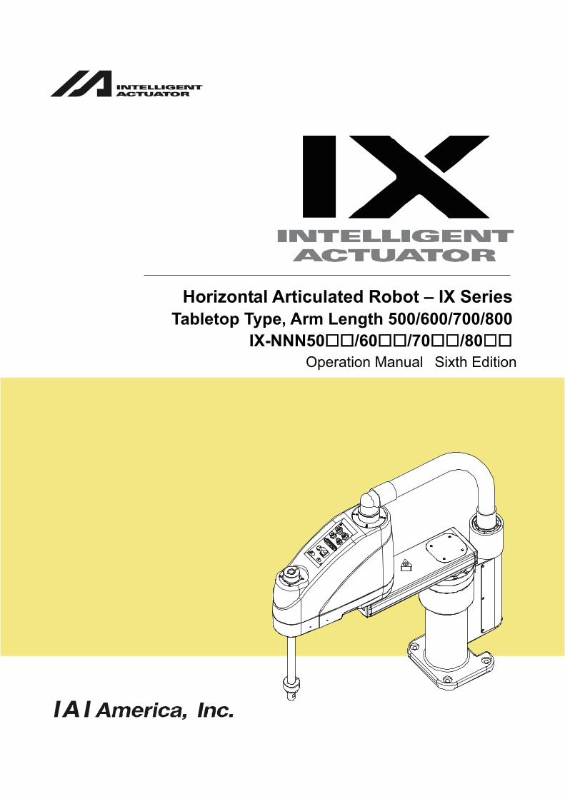
Tabletop Type, Arm Length 500/600/700/800IX-NNN50 /60 /70 /80
Operation Manual Sixth Edition
Horizontal Articulated Robot – IX Series

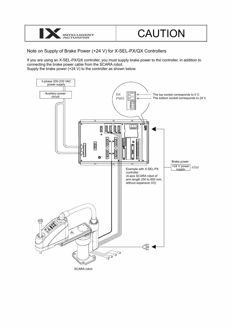
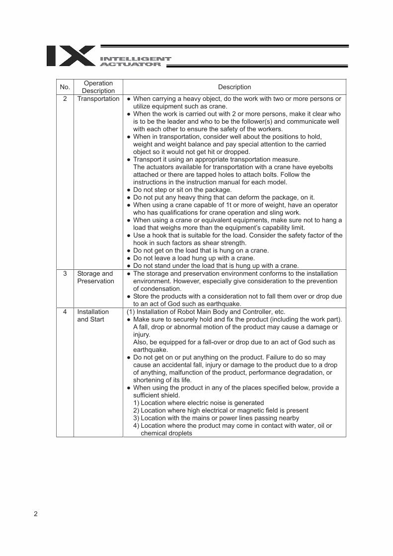
CAUTIONNote on Supply of Brake Power (+24 V) for X-SEL-PX/QX Controllers
If you are using an X-SEL-PX/QX controller, you must supply brake power to the controller, in addition to connecting the brake power cable from the SCARA robot. Supply the brake power (+24 V) to the controller as shown below.
3-phase 200-230 VAC power supply
Auxiliary power circuit The top socket corresponds to 0 V.
The bottom socket corresponds to 24 V.
Example with X-SEL-PX controller(4-axis SCARA robot of arm length 250 to 600 mm,without expansion I/O)
Brake power +24 V power
supply
SCARA robot
Please Read Before UseThank you for purchasing an IAI product.
This operation manual explains the handling methods, structure and maintenance of this product, amongothers, providing the information you need to know to use the product safely.
Before using the product, be sure to read this manual and fully understand the contents explained hereinto ensure safe use of the product.The CD or DVD that comes with the product contains operation manuals for IAI products.When using the product, refer to the necessary portions of the applicable operation manual by printingthem out or displaying them on a PC.
After reading the operation manual, keep it in a convenient place so that whoever is handling this productcan reference it quickly when necessary.
[Important]The product cannot be operated in any way unless expressly specified in this operationmanual. IAI shall assume no responsibility for the outcome of any operation not specifiedherein.Information contained in this operation manual is subject to change without notice for thepurpose of product improvement.This operation manual is original.If you have any question or comment regarding the content of this manual, please contactthe IAI sales office near you.Unauthorized use or reproduction of this operation manual, whether in whole or in part, is strictlyprohibited.

CE Marking
If a compliance with the CE Marking is required, please follow Overseas Standards Compliance Manual(ME0287) that is provided separately.

Table of Contents
Safety Guide ······················································································································1Caution in Handling ···········································································································81. Names of Robot Parts ································································································9
1.1 Names of Parts ·····························································································································91.2 Labels ·········································································································································101.3 Label Positions ···························································································································11
2. Transportation and Handling ··················································································· 122.1 Handling of the Carton ················································································································122.2 Packing Condition of the Robot ··································································································122.3 Handling of Individual Components ····························································································132.4 Checking after Unpacking ··········································································································132.5 Transporting the Robot ···············································································································14
3. Installation Environment and Storage Environment ················································ 153.1 Installation Environment ·············································································································153.2 Installation Platform ····················································································································153.3 Storage Environment ··················································································································15
4. How to Install ··········································································································· 174.1 Installation Posture ·····················································································································174.2 Installing the Robot ·····················································································································184.3 Connecting the Controller ···········································································································194.4 Checking after Installation ··········································································································21
5. Precautions for Use ································································································· 225.1 Reference Acceleration/Deceleration Settings ···········································································225.2 Tools ···········································································································································245.3 Carrying Load ·····························································································································255.4 User Wiring and Piping ···············································································································26
6. Inspection/Maintenance ·························································································· 286.1 Inspection/Maintenance ··············································································································286.2 Battery Replacement ··················································································································306.3 Absolute Reset Procedure ··········································································································33
7. Specifi cations ·········································································································· 507.1 Specifi cation Table ······················································································································507.2 External Dimensions ···················································································································587.3 Robot Operation Area ·················································································································627.4 Wiring Diagram ···························································································································647.5 230V Circuit Components ···········································································································70

8. Warranty ·················································································································· 718.1 Warranty Period ··························································································································718.2 Scope of Warranty ······················································································································718.3 Honoring the Warranty ················································································································718.4 Limited Liability ···························································································································718.5 Conditions of Conformance with Applicable Standards/Regulations, Etc., and Applications ·····728.6 Other Items Excluded from Warranty ·························································································72
Change History ··············································································································· 73
1
Safety Guide“Safety Guide” has been written to use the machine safely and so prevent personal injury or property damage beforehand. Make sure to read it before the operation of this product.
Safety Precautions for Our Products The common safety precautions for the use of any of our robots in each operation.
No. Operation Description Description
1 Model Selection
� This product has not been planned and designed for the application where high level of safety is required, so the guarantee of the protection of human life is impossible. Accordingly, do not use it in any of the following applications. 1) Medical equipment used to maintain, control or otherwise affect
human life or physical health. 2) Mechanisms and machinery designed for the purpose of moving or
transporting people (For vehicle, railway facility or air navigation facility)
3) Important safety parts of machinery (Safety device, etc.) � Do not use the product outside the specifications. Failure to do so may
considerably shorten the life of the product. � Do not use it in any of the following environments.
1) Location where there is any inflammable gas, inflammable object or explosive
2) Place with potential exposure to radiation 3) Location with the ambient temperature or relative humidity exceeding
the specification range 4) Location where radiant heat is added from direct sunlight or other
large heat source 5) Location where condensation occurs due to abrupt temperature
changes 6) Location where there is any corrosive gas (sulfuric acid or
hydrochloric acid) 7) Location exposed to significant amount of dust, salt or iron powder 8) Location subject to direct vibration or impact
� For an actuator used in vertical orientation, select a model which is equipped with a brake. If selecting a model with no brake, the moving part may drop when the power is turned OFF and may cause an accident such as an injury or damage on the work piece.
2
No. Operation Description Description
2 Transportation � When carrying a heavy object, do the work with two or more persons or utilize equipment such as crane.
� When the work is carried out with 2 or more persons, make it clear who is to be the leader and who to be the follower(s) and communicate well with each other to ensure the safety of the workers.
� When in transportation, consider well about the positions to hold, weight and weight balance and pay special attention to the carried object so it would not get hit or dropped.
� Transport it using an appropriate transportation measure. The actuators available for transportation with a crane have eyebolts attached or there are tapped holes to attach bolts. Follow the instructions in the instruction manual for each model.
� Do not step or sit on the package. � Do not put any heavy thing that can deform the package, on it. � When using a crane capable of 1t or more of weight, have an operator
who has qualifications for crane operation and sling work. � When using a crane or equivalent equipments, make sure not to hang a
load that weighs more than the equipment’s capability limit. � Use a hook that is suitable for the load. Consider the safety factor of the
hook in such factors as shear strength. � Do not get on the load that is hung on a crane. � Do not leave a load hung up with a crane. � Do not stand under the load that is hung up with a crane.
3 Storage and Preservation
� The storage and preservation environment conforms to the installation environment. However, especially give consideration to the prevention of condensation.
� Store the products with a consideration not to fall them over or drop due to an act of God such as earthquake.
4 Installation and Start
(1) Installation of Robot Main Body and Controller, etc. � Make sure to securely hold and fix the product (including the work part).
A fall, drop or abnormal motion of the product may cause a damage or injury. Also, be equipped for a fall-over or drop due to an act of God such as earthquake.
� Do not get on or put anything on the product. Failure to do so may cause an accidental fall, injury or damage to the product due to a drop of anything, malfunction of the product, performance degradation, or shortening of its life.
� When using the product in any of the places specified below, provide a sufficient shield. 1) Location where electric noise is generated 2) Location where high electrical or magnetic field is present 3) Location with the mains or power lines passing nearby 4) Location where the product may come in contact with water, oil or
chemical droplets
3
No. Operation Description Description
(2) Cable Wiring � Use our company’s genuine cables for connecting between the actuator
and controller, and for the teaching tool. � Do not scratch on the cable. Do not bend it forcibly. Do not pull it. Do
not coil it around. Do not insert it. Do not put any heavy thing on it. Failure to do so may cause a fire, electric shock or malfunction due to leakage or continuity error.
� Perform the wiring for the product, after turning OFF the power to the unit, so that there is no wiring error.
� When the direct current power (+24V) is connected, take the great care of the directions of positive and negative poles. If the connection direction is not correct, it might cause a fire, product breakdown or malfunction.
� Connect the cable connector securely so that there is no disconnection or looseness. Failure to do so may cause a fire, electric shock or malfunction of the product.
� Never cut and/or reconnect the cables supplied with the product for the purpose of extending or shortening the cable length. Failure to do so may cause the product to malfunction or cause fire.
4 Installation and Start
(3) Grounding � The grounding operation should be performed to prevent an electric
shock or electrostatic charge, enhance the noise-resistance ability and control the unnecessary electromagnetic radiation.
� For the ground terminal on the AC power cable of the controller and the grounding plate in the control panel, make sure to use a twisted pair cable with wire thickness 0.5mm2 (AWG20 or equivalent) or more for grounding work. For security grounding, it is necessary to select an appropriate wire thickness suitable for the load. Perform wiring that satisfies the specifications (electrical equipment technical standards).
� Perform Class D Grounding (former Class 3 Grounding with ground resistance 100� or below).
4
No. Operation Description Description
4 Installation and Start
(4) Safety Measures � When the work is carried out with 2 or more persons, make it clear who
is to be the leader and who to be the follower(s) and communicate well with each other to ensure the safety of the workers.
� When the product is under operation or in the ready mode, take the safety measures (such as the installation of safety and protection fence) so that nobody can enter the area within the robot’s movable range. When the robot under operation is touched, it may result in death or serious injury.
� Make sure to install the emergency stop circuit so that the unit can be stopped immediately in an emergency during the unit operation.
� Take the safety measure not to start up the unit only with the power turning ON. Failure to do so may start up the machine suddenly and cause an injury or damage to the product.
� Take the safety measure not to start up the machine only with the emergency stop cancellation or recovery after the power failure. Failure to do so may result in an electric shock or injury due to unexpected power input.
� When the installation or adjustment operation is to be performed, give clear warnings such as “Under Operation; Do not turn ON the power!” etc. Sudden power input may cause an electric shock or injury.
� Take the measure so that the work part is not dropped in power failure or emergency stop.
� Wear protection gloves, goggle or safety shoes, as necessary, to secure safety.
� Do not insert a finger or object in the openings in the product. Failure to do so may cause an injury, electric shock, damage to the product or fire.
� When releasing the brake on a vertically oriented actuator, exercise precaution not to pinch your hand or damage the work parts with the actuator dropped by gravity.
5 Teaching � When the work is carried out with 2 or more persons, make it clear who is to be the leader and who to be the follower(s) and communicate well with each other to ensure the safety of the workers.
� Perform the teaching operation from outside the safety protection fence, if possible. In the case that the operation is to be performed unavoidably inside the safety protection fence, prepare the “Stipulations for the Operation” and make sure that all the workers acknowledge and understand them well.
� When the operation is to be performed inside the safety protection fence, the worker should have an emergency stop switch at hand with him so that the unit can be stopped any time in an emergency.
� When the operation is to be performed inside the safety protection fence, in addition to the workers, arrange a watchman so that the machine can be stopped any time in an emergency. Also, keep watch on the operation so that any third person can not operate the switches carelessly.
� Place a sign “Under Operation” at the position easy to see. � When releasing the brake on a vertically oriented actuator, exercise
precaution not to pinch your hand or damage the work parts with the actuator dropped by gravity.
* Safety protection Fence : In the case that there is no safety protection fence, the movable range should be indicated.
5
No. Operation Description Description
6 Trial Operation
� When the work is carried out with 2 or more persons, make it clear who is to be the leader and who to be the follower(s) and communicate well with each other to ensure the safety of the workers.
� After the teaching or programming operation, perform the check operation one step by one step and then shift to the automatic operation.
� When the check operation is to be performed inside the safety protection fence, perform the check operation using the previously specified work procedure like the teaching operation.
� Make sure to perform the programmed operation check at the safety speed. Failure to do so may result in an accident due to unexpected motion caused by a program error, etc.
� Do not touch the terminal block or any of the various setting switches in the power ON mode. Failure to do so may result in an electric shock or malfunction.
7 Automatic Operation
� Check before starting the automatic operation or rebooting after operation stop that there is nobody in the safety protection fence.
� Before starting automatic operation, make sure that all peripheral equipment is in an automatic-operation-ready state and there is no alarm indication.
� Make sure to operate automatic operation start from outside of the safety protection fence.
� In the case that there is any abnormal heating, smoke, offensive smell, or abnormal noise in the product, immediately stop the machine and turn OFF the power switch. Failure to do so may result in a fire or damage to the product.
� When a power failure occurs, turn OFF the power switch. Failure to do so may cause an injury or damage to the product, due to a sudden motion of the product in the recovery operation from the power failure.
6
No. Operation Description Description
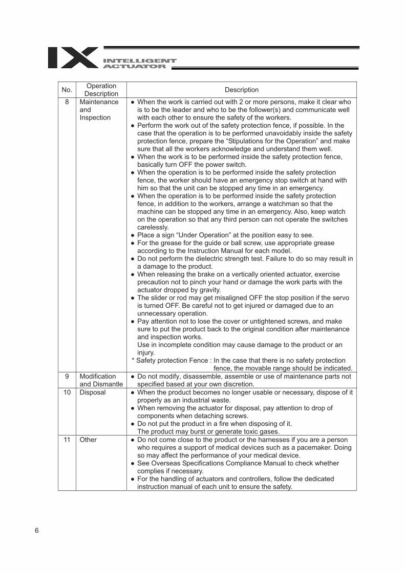
8 Maintenance andInspection
� When the work is carried out with 2 or more persons, make it clear who is to be the leader and who to be the follower(s) and communicate well with each other to ensure the safety of the workers.
� Perform the work out of the safety protection fence, if possible. In the case that the operation is to be performed unavoidably inside the safety protection fence, prepare the “Stipulations for the Operation” and make sure that all the workers acknowledge and understand them well.
� When the work is to be performed inside the safety protection fence, basically turn OFF the power switch.
� When the operation is to be performed inside the safety protection fence, the worker should have an emergency stop switch at hand with him so that the unit can be stopped any time in an emergency.
� When the operation is to be performed inside the safety protection fence, in addition to the workers, arrange a watchman so that the machine can be stopped any time in an emergency. Also, keep watch on the operation so that any third person can not operate the switches carelessly.
� Place a sign “Under Operation” at the position easy to see. � For the grease for the guide or ball screw, use appropriate grease
according to the Instruction Manual for each model. � Do not perform the dielectric strength test. Failure to do so may result in
a damage to the product. � When releasing the brake on a vertically oriented actuator, exercise
precaution not to pinch your hand or damage the work parts with the actuator dropped by gravity.
� The slider or rod may get misaligned OFF the stop position if the servo is turned OFF. Be careful not to get injured or damaged due to an unnecessary operation.
� Pay attention not to lose the cover or untightened screws, and make sure to put the product back to the original condition after maintenance and inspection works. Use in incomplete condition may cause damage to the product or an injury.
* Safety protection Fence : In the case that there is no safety protection fence, the movable range should be indicated.
9 Modification and Dismantle
� Do not modify, disassemble, assemble or use of maintenance parts not specified based at your own discretion.
10 Disposal � When the product becomes no longer usable or necessary, dispose of it properly as an industrial waste.
� When removing the actuator for disposal, pay attention to drop of components when detaching screws.
� Do not put the product in a fire when disposing of it. The product may burst or generate toxic gases.
11 Other � Do not come close to the product or the harnesses if you are a person who requires a support of medical devices such as a pacemaker. Doing so may affect the performance of your medical device.
� See Overseas Specifications Compliance Manual to check whether complies if necessary.
� For the handling of actuators and controllers, follow the dedicated instruction manual of each unit to ensure the safety.

7
Alert Indication The safety precautions are divided into “Danger”, “Warning”, “Caution” and “Notice” according to the warning level, as follows, and described in the Instruction Manual for each model.
Level Degree of Danger and Damage Symbol
Danger This indicates an imminently hazardous situation which, if the product is not handled correctly, will result in death or serious injury.
Danger
Warning This indicates a potentially hazardous situation which, if the product is not handled correctly, could result in death or serious injury.
Warning
Caution This indicates a potentially hazardous situation which, if the product is not handled correctly, may result in minor injury or property damage.
Caution
Notice This indicates lower possibility for the injury, but should be kept to use this product properly. Notice

8
Caution in Handling
1. Make sure to attach the vertical articulated robot properly by following this operation manual.Using the product with the vertical articulated robot not being certainly retained or affixed may cause abnormal noise, vibration, malfunction or shorten the product life.
9
1. Nam
es of Robot P
arts
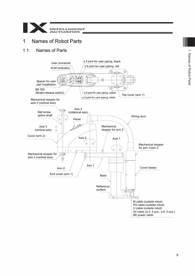
1 Names of Robot Parts
1.1 Names of Parts
User connector
ALM (indicator)
� 4 joint for user piping, black
� 6 joint for user piping, red
Spacer for user part installation
BK SW (Brake-release switch)
� 4 joint for user piping, white
� 6 joint for user piping, yellow Top cover (arm 1)
Mechanical stopper for axis 3 (vertical axis)
Axis 4 (rotational axis)
Panel
Ball screw spline shaft
Cover (arm 2)
Wiring duct
Mechanical stopper for axis 3 (vertical axis)
Axis 3 (vertical axis)
Axis 2
Arm 2
End cover (arm 1)
Arm 1
Base
Cover (base)
Mechanical stopper for arm 1/arm 2
Axis 1
Mechanical stopper for arm 2
Reference surface
M cable (outside robot) PG cable (outside robot) U cable (outside robot) Air tubes (� 4: 2 pcs., � 6: 2 pcs.) BK power cable
10
1. N
ames
of R
obot
Par
ts
Danger Warning Caution
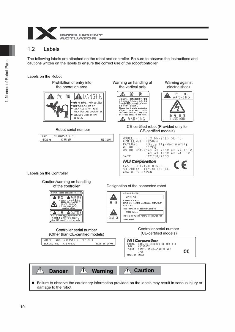
1.2 Labels
The following labels are attached on the robot and controller. Be sure to observe the instructions and cautions written on the labels to ensure the correct use of the robot/controller.
Labels on the Robot
Labels on the Controller
� Failure to observe the cautionary information provided on the labels may result in serious injury or damage to the robot.
Prohibition of entry into the operation area
Warning on handling of the vertical axis
Warning against electric shock
Robot serial number CE-certified robot (Provided only for
CE-certified models)
Caution/warning on handling of the controller Designation of the connected robot
Controller serial number (Other than CE-certified models)
Controller serial number (CE-certified models)
Rate
11
1. Nam
es of Robot P
arts
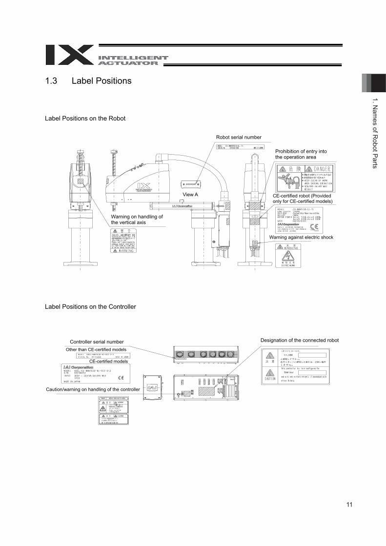
1.3 Label Positions
Label Positions on the Robot
Label Positions on the Controller
View A
Warning on handling of the vertical axis
Warning against electric shock
Robot serial number
CE-certified robot (Provided only for CE-certified models)
Designation of the connected robot Controller serial number
CE-certified models
Other than CE-certified models
Caution/warning on handling of the controller
Prohibition of entry into the operation area
12
2. T
rans
porta
tion
and
Han
dlin
g
Warning Caution
2 Transportation and Handling
2.1 Handling of the Carton
Each robot is packed with a controller prior to shipment. When transporting the carton containing the robot and controller, observe the following items and be careful not to drop the carton or apply impact due to forcible contact:
� If the carton is heavy, one operator should not attempt to carry it alone. � Place the carton on a level surface if it is to be left there for a while. � Do not climb upon the carton. � Do not place on the carton any heavy object that may cause the carton to deform, or an article
whose shape allows a load to be concentrated at one point.
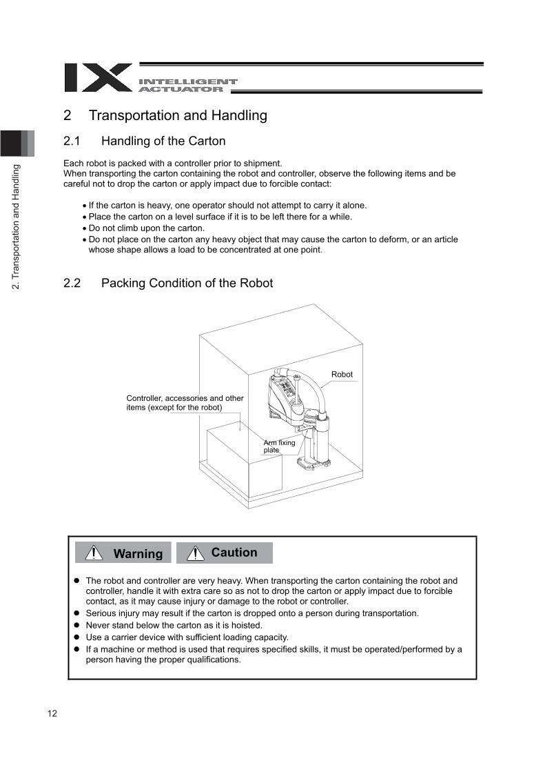
2.2 Packing Condition of the Robot
� The robot and controller are very heavy. When transporting the carton containing the robot and controller, handle it with extra care so as not to drop the carton or apply impact due to forcible contact, as it may cause injury or damage to the robot or controller.
� Serious injury may result if the carton is dropped onto a person during transportation. � Never stand below the carton as it is hoisted. � Use a carrier device with sufficient loading capacity. � If a machine or method is used that requires specified skills, it must be operated/performed by a
person having the proper qualifications.
Arm fixingplate
Controller, accessories and other items (except for the robot)
Robot
13
2. Transportation and Handling
Caution
2.3 Handling of Individual Components The robot and controller are supplied as a set. Your robot cannot be used with the controller supplied with another robot. When handling multiple robots, be careful not to lose their correct pairings with the controllers.
The robot will not stand on its own after being unloaded from the carton pallet. Hold it by hand, or place a cushioning material on the floor and place the robot on its side upon the cushion.
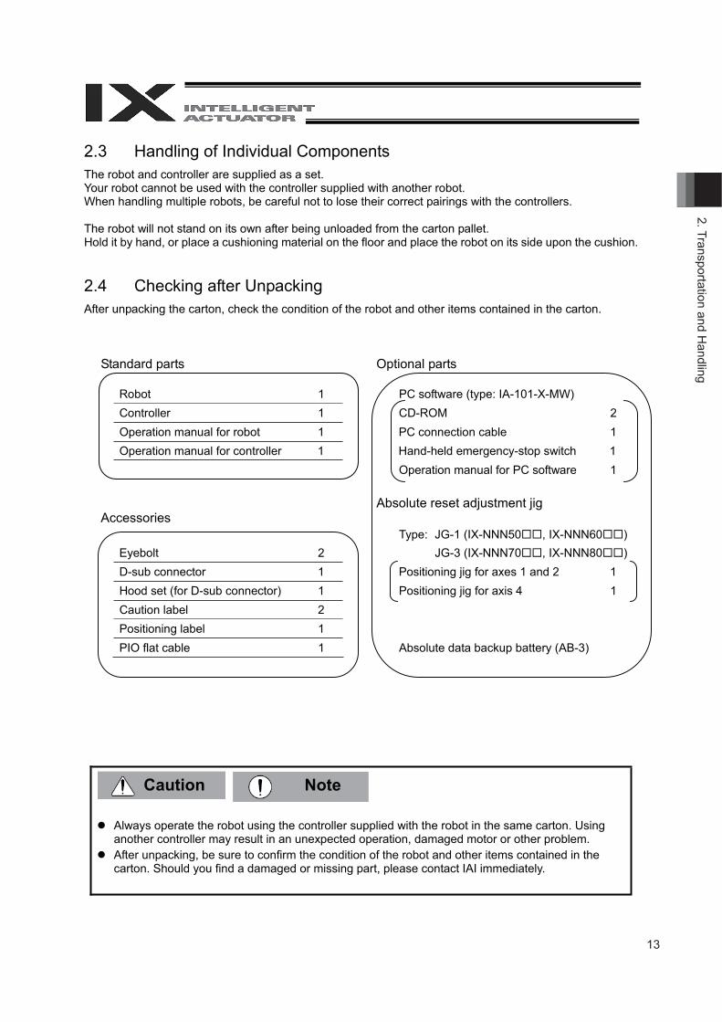
2.4 Checking after Unpacking After unpacking the carton, check the condition of the robot and other items contained in the carton.
Standard parts Optional parts
Robot 1 PC software (type: IA-101-X-MW) Controller 1 CD-ROM 2 Operation manual for robot 1 PC connection cable 1Operation manual for controller 1 Hand-held emergency-stop switch 1
Operation manual for PC software 1
Absolute reset adjustment jig Accessories
Type: JG-1 (IX-NNN50��, IX-NNN60��)Eyebolt 2 JG-3 (IX-NNN70��, IX-NNN80��)D-sub connector 1 Positioning jig for axes 1 and 2 1 Hood set (for D-sub connector) 1 Positioning jig for axis 4 1Caution label 2 Positioning label 1 PIO flat cable 1 Absolute data backup battery (AB-3)
� Always operate the robot using the controller supplied with the robot in the same carton. Using another controller may result in an unexpected operation, damaged motor or other problem.
� After unpacking, be sure to confirm the condition of the robot and other items contained in the carton. Should you find a damaged or missing part, please contact IAI immediately.
Note
14
2. T
rans
porta
tion
and
Han
dlin
g
Danger Warning
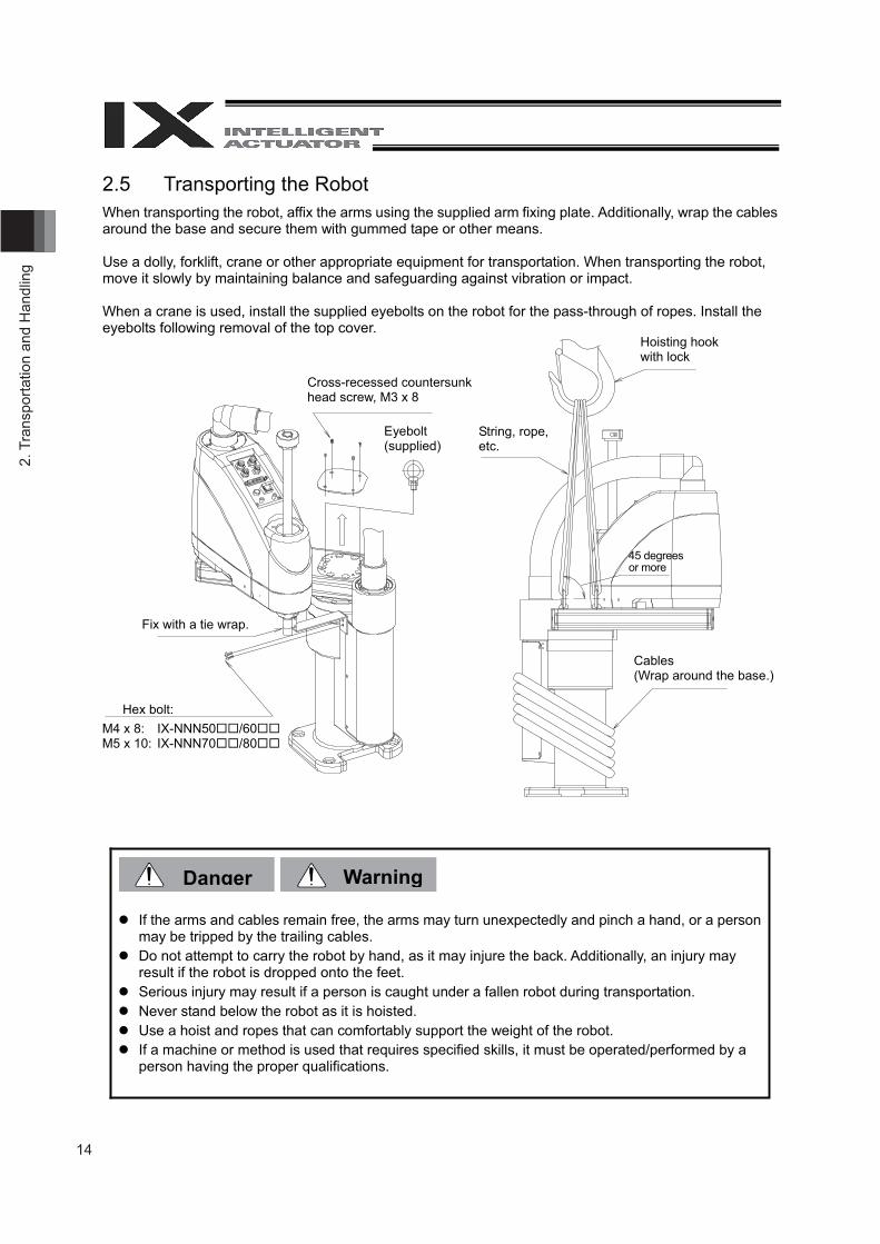
2.5 Transporting the Robot When transporting the robot, affix the arms using the supplied arm fixing plate. Additionally, wrap the cables around the base and secure them with gummed tape or other means.
Use a dolly, forklift, crane or other appropriate equipment for transportation. When transporting the robot, move it slowly by maintaining balance and safeguarding against vibration or impact.
When a crane is used, install the supplied eyebolts on the robot for the pass-through of ropes. Install the eyebolts following removal of the top cover.
� If the arms and cables remain free, the arms may turn unexpectedly and pinch a hand, or a person may be tripped by the trailing cables.
� Do not attempt to carry the robot by hand, as it may injure the back. Additionally, an injury may result if the robot is dropped onto the feet.
� Serious injury may result if a person is caught under a fallen robot during transportation. � Never stand below the robot as it is hoisted. � Use a hoist and ropes that can comfortably support the weight of the robot. � If a machine or method is used that requires specified skills, it must be operated/performed by a
person having the proper qualifications.
Cross-recessed countersunk head screw, M3 x 8
Eyebolt (supplied)
Fix with a tie wrap.
Hex bolt: M4 x 8: IX-NNN50��/60��M5 x 10: IX-NNN70��/80��
String, rope, etc.
Hoisting hook with lock
45 degrees or more
Cables (Wrap around the base.)
15
3. Installation Environm
ent and Storage E
nvironment
3 Installation Environment and Storage Environment
3.1 Installation Environment Install the robot in an environment that satisfies the following conditions:
� Away from direct sunlight � Not subject to radiated heat from a high-capacity energy source such as a heat-treating furnace � Ambient temperature: 0�C to 40�C� Humidity: 85% or less (non-condensing) � Not exposed to corrosive or flammable gases � Not subject to impact or vibration � Not exposed to a significant amount of electromagnetic waves, ultraviolet rays or radiation � Sufficient space is available to ensure safety in teaching and maintenance/inspection operations
Generally, the robot must be installed where the operator need not wear protective gear in order to work.
3.2 Installation Platform The platform on which to install the robot receives a significant reactive force. Be certain the platform has sufficient rigidity to withstand the anticipated force.
� The surface on which the robot is fixed must have a thickness of 25 mm or more. The levelness of the robot installation surface must be at least �0.05 mm. � Drill tapped holes, as indicated below, into the installation surface of the platform.
Type Tap size Remarks
IX-NNN50��/60�� M10 Effective thread: 10 mm or longer for steel (20 mm or longer for aluminum)
IX-NNN70��/80�� M12 Effective thread: 12 mm or longer for steel (24mm or longer for aluminum)
� The platform must have sufficient rigidity to withstand not only the weight of the robot but also the dynamic moment of inertia that is generated when the robot is operated at maximum speed. � Secure the platform to the floor or other rigid structure in a manner that prevents any movement due
to operation of the robot. � The installation platform must allow the robot to be mounted on a level surface.
16
3. In
stal
latio
n E
nviro
nmen
t and
Sto
rage
Env
ironm
ent
Danger Warning
3.3 Storage Environment The storage environment conforms to the installation environment. If the robot is to be stored for a prolonged period of time, be sure the robot will not be exposed to dew condensation. Unless otherwise specified, desiccant is not placed in the carton when shipped. If the robot is to be kept in an environment subject to condensation, provide preventive measures from over the carton or directly to the robot after unpacking. The maximum storage temperature is 60�C for a short storage period. If the robot is to be stored for more than a month, the ambient temperature should not exceed 50�C.
� Failure to provide a proper environment for installation and storage may shorten the service life of the robot, reduce its operation accuracy, or cause a malfunction or failure.
� Never use the robot in a flammable atmosphere. The robot may explode or ignite.
17
4. How
to Install
4
4.1
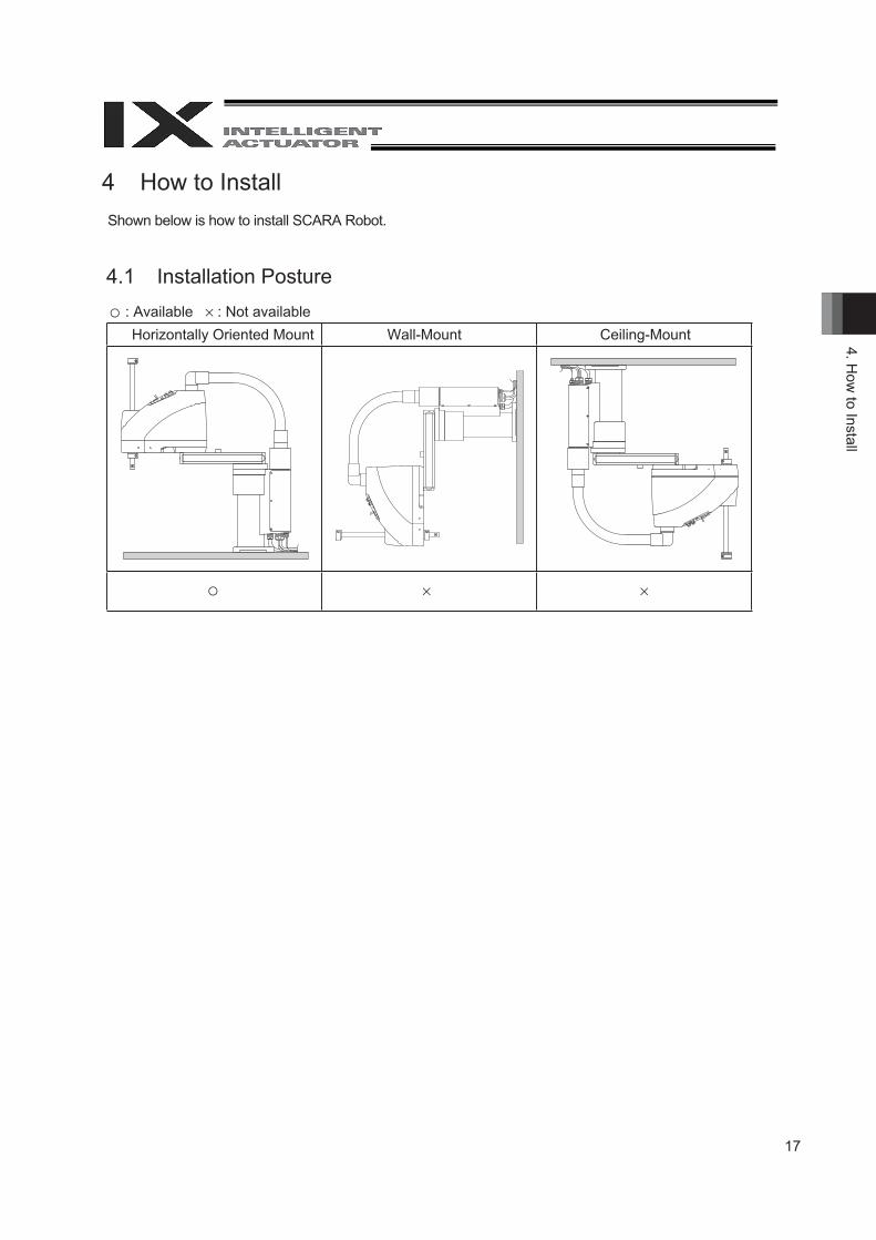
How to InstallShown below is how to install SCARA Robot.
Installation Posture
Ceiling-MountWall-MountHorizontally Oriented Mount : Available : Not available
18
4. H
ow to
Inst
all
Warning Caution
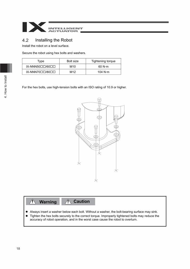
4.1 Installing the Robot Install the robot on a level surface.
Secure the robot using hex bolts and washers.
Type Bolt size Tightening torque
IX-NNN50 /60 M10 60 N m
IX-NNN70 /80 M12 104 N m
For the hex bolts, use high-tension bolts with an ISO rating of 10.9 or higher.
Always insert a washer below each bolt. Without a washer, the bolt-bearing surface may sink. Tighten the hex bolts securely to the correct torque. Improperly tightened bolts may reduce the
accuracy of robot operation, and in the worst case cause the robot to overturn.
4.2
19
4. How
to Install
Warning
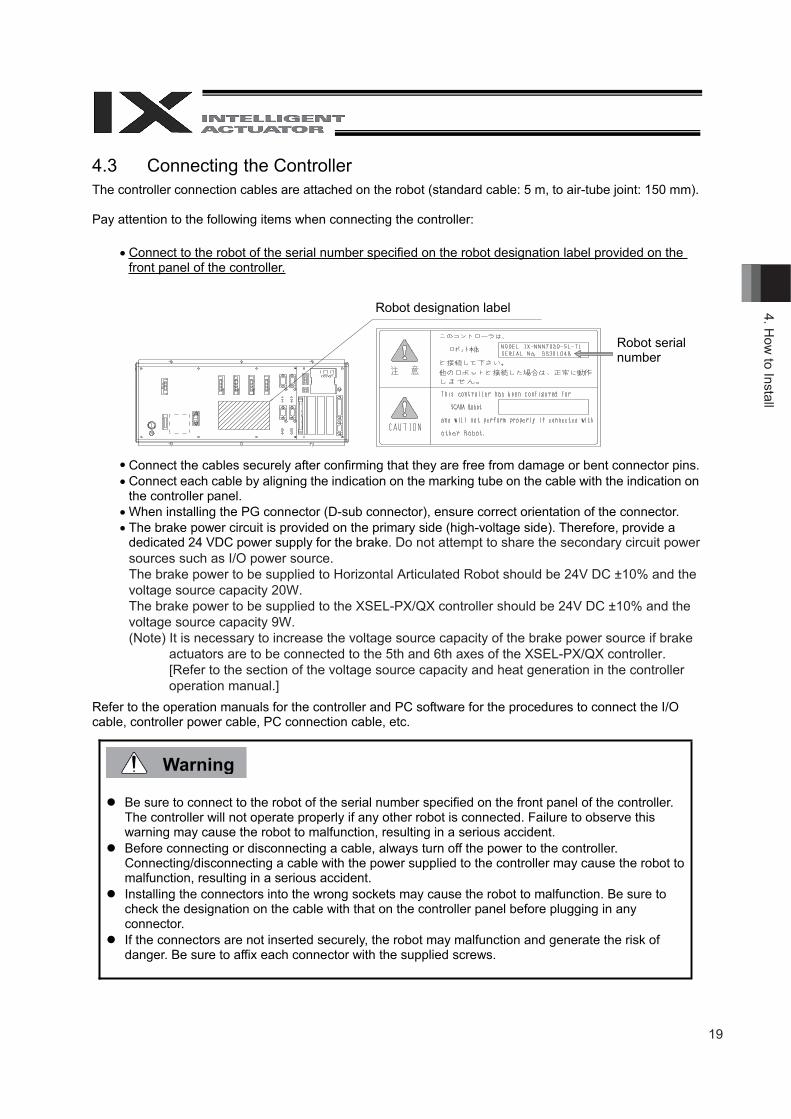
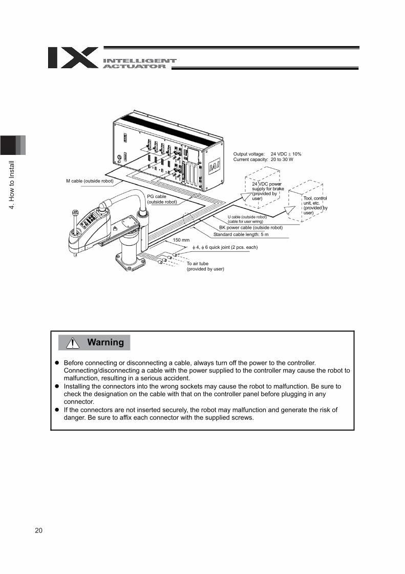
4.3 Connecting the ControllerThe controller connection cables are attached on the robot (standard cable: 5 m, to air-tube joint: 150 mm).
Pay attention to the following items when connecting the controller:
Connect to the robot of the serial number specified on the robot designation label provided on thefront panel of the controller.
Connect the cables securely after confirming that they are free from damage or bent connector pins.Connect each cable by aligning the indication on the marking tube on the cable with the indication onthe controller panel.When installing the PG connector (D-sub connector), ensure correct orientation of the connector.The brake power circuit is provided on the primary side (high-voltage side). Therefore, provide adedicated 24 VDC power supply for the brake. Do not attempt to share the secondary circuit power sources such as I/O power source.The brake power to be supplied to Horizontal Articulated Robot should be 24V DC ±10% and the voltage source capacity 20W.The brake power to be supplied to the XSEL-PX/QX controller should be 24V DC ±10% and the voltage source capacity 9W.(Note) It is necessary to increase the voltage source capacity of the brake power source if brake
actuators are to be connected to the 5th and 6th axes of the XSEL-PX/QX controller. [Refer to the section of the voltage source capacity and heat generation in the controller operation manual.]
Refer to the operation manuals for the controller and PC software for the procedures to connect the I/Ocable, controller power cable, PC connection cable, etc.
Be sure to connect to the robot of the serial number specified on the front panel of the controller.The controller will not operate properly if any other robot is connected. Failure to observe this warning may cause the robot to malfunction, resulting in a serious accident.Before connecting or disconnecting a cable, always turn off the power to the controller.Connecting/disconnecting a cable with the power supplied to the controller may cause the robot tomalfunction, resulting in a serious accident.Installing the connectors into the wrong sockets may cause the robot to malfunction. Be sure tocheck the designation on the cable with that on the controller panel before plugging in anyconnector.If the connectors are not inserted securely, the robot may malfunction and generate the risk ofdanger. Be sure to affix each connector with the supplied screws.
Robot designation label
Robot serialnumber
20
4. H
ow to
Inst
all
Before connecting or disconnecting a cable, always turn off the power to the controller. Connecting/disconnecting a cable with the power supplied to the controller may cause the robot to malfunction, resulting in a serious accident.
Installing the connectors into the wrong sockets may cause the robot to malfunction. Be sure to check the designation on the cable with that on the controller panel before plugging in any connector.
If the connectors are not inserted securely, the robot may malfunction and generate the risk of danger. Be sure to affix each connector with the supplied screws.
M cable (outside robot)
Output voltage: 24 VDC 10% Current capacity: 20 to 30 W
PG cable (outside robot)
To air tube (provided by user)
4, 6 quick joint (2 pcs. each)
Standard cable length: 5 m
U cable (outside robot) (cable for user wiring)
24 VDC power supply for brake (provided by user) Tool, control
unit, etc. (provided by user)
BK power cable (outside robot)
150 mm
Warning
21
4. How
to Install
4.3 Checking after Installation Once the robot has been installed, check the following items:
Visually check the robot, controller and cables for dents and other abnormalities. Confirm that the cables are connected properly and that the connectors are inserted securely.
Failure to perform these checks may result in a malfunctioning robot or a damaged controller or robot.
Warning
4.4
22
5. P
reca
utio
ns fo
r Use
Caution
5 Precautions for Use
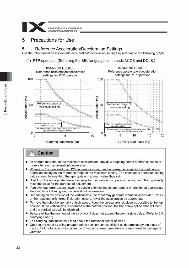
5.1 Reference Acceleration/Deceleration Settings Use the robot based on appropriate acceleration/deceleration settings by referring to the following graph:
(1) PTP operation (Set using the SEL language commands ACCS and DCLS.)
To operate the robot at the maximum acceleration, provide a stopping period of three seconds or more after each acceleration/deceleration.
When arm 1 is operated over 125 degrees or more, use the reference range for the continuous operation setting as the reference range of the maximum setting. The continuous operation setting value should be one-third the appropriate maximum value thus set.
Start from the appropriate reference range for the continuous operation setting, and then gradually raise the value for the purpose of adjustment.
If an overload error occurs, lower the acceleration setting as appropriate or provide an appropriate stopping time following each acceleration/deceleration.
Depending on the position of the vertical axis, the robot may generate vibration when axis 1, axis 2 or the rotational axis turns. If vibration occurs, lower the acceleration as appropriate.
To move the robot horizontally at high speed, keep the vertical axis as close as possible to the top position. If the vertical axis is operated at the bottom position, the ball screw spline shaft will bend and the vertical axis will be disabled.
Be careful that the moment of inertia of axis 4 does not exceed the permissible value. (Refer to 5.3, “Carrying Load.”)
The carrying load indicates a load above the rotational center of axis 4. Operate the robot by using an appropriate acceleration coefficient as determined by the mass of
the tip. Failure to do so may cause the drive part to wear prematurely or may result in damage or vibration.
IX-NNN50 /60Reference acceleration/deceleration
settings for PTP operation
Acc
eler
atio
n (%
)
Carrying load mass (kg)
Reference range of maximum setting
0 5 10
100
50
0
IX-NNN70 /80Reference acceleration/deceleration
settings for PTP operation
Acc
eler
atio
n (%
)
Carrying load mass (kg)
100
50
00 5 10 15 20
Reference range for continuous operation setting
Reference range of maximum setting when arm 1 is operated over 125 degrees or more
Reference range of maximum setting
Reference range for continuous operation setting
Reference range of maximum setting when arm 1 is operated over 125 degrees or more
23
5. Precautions for U
se
Caution
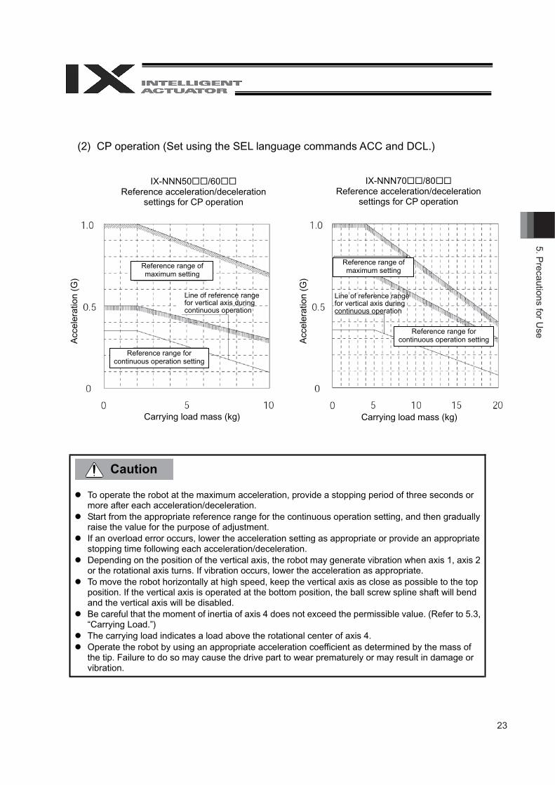
(2) CP operation (Set using the SEL language commands ACC and DCL.)
To operate the robot at the maximum acceleration, provide a stopping period of three seconds or more after each acceleration/deceleration.
Start from the appropriate reference range for the continuous operation setting, and then gradually raise the value for the purpose of adjustment.
If an overload error occurs, lower the acceleration setting as appropriate or provide an appropriate stopping time following each acceleration/deceleration.
Depending on the position of the vertical axis, the robot may generate vibration when axis 1, axis 2 or the rotational axis turns. If vibration occurs, lower the acceleration as appropriate.
To move the robot horizontally at high speed, keep the vertical axis as close as possible to the top position. If the vertical axis is operated at the bottom position, the ball screw spline shaft will bend and the vertical axis will be disabled.
Be careful that the moment of inertia of axis 4 does not exceed the permissible value. (Refer to 5.3, “Carrying Load.”)
The carrying load indicates a load above the rotational center of axis 4. Operate the robot by using an appropriate acceleration coefficient as determined by the mass of
the tip. Failure to do so may cause the drive part to wear prematurely or may result in damage or vibration.
IX-NNN50 /60Reference acceleration/deceleration
settings for CP operation
IX-NNN70 /80Reference acceleration/deceleration
settings for CP operation
Acc
eler
atio
n (G
)
Carrying load mass (kg)
Acc
eler
atio
n (G
)
Carrying load mass (kg)
Reference range of maximum setting
Reference range of maximum setting
Reference range for continuous operation setting
Reference range for continuous operation setting
Line of reference range for vertical axis during continuous operation
Line of reference range for vertical axis during continuous operation
24
5. P
reca
utio
ns fo
r Use
Warning Caution
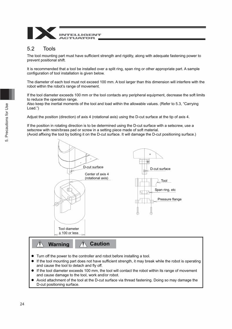
5.2 Tools The tool mounting part must have sufficient strength and rigidity, along with adequate fastening power to prevent positional shift.
It is recommended that a tool be installed over a split ring, span ring or other appropriate part. A sample configuration of tool installation is given below.
The diameter of each tool must not exceed 100 mm. A tool larger than this dimension will interfere with the robot within the robot’s range of movement.
If the tool diameter exceeds 100 mm or the tool contacts any peripheral equipment, decrease the soft limits to reduce the operation range. Also keep the inertial moments of the tool and load within the allowable values. (Refer to 5.3, “Carrying Load.”)
Adjust the position (direction) of axis 4 (rotational axis) using the D-cut surface at the tip of axis 4.
If the position in rotating direction is to be determined using the D-cut surface with a setscrew, use a setscrew with resin/brass pad or screw in a setting piece made of soft material. (Avoid affixing the tool by bolting it on the D-cut surface. It will damage the D-cut positioning surface.)
Turn off the power to the controller and robot before installing a tool. If the tool mounting part does not have sufficient strength, it may break while the robot is operating
and cause the tool to detach and fly off. If the tool diameter exceeds 100 mm, the tool will contact the robot within its range of movement
and cause damage to the tool, work and/or robot. Avoid attachment of the tool at the D-cut surface via thread fastening. Doing so may damage the
D-cut positioning surface.
D-cut surface
Center of axis 4 (rotational axis)
Tool diameter 100 or less
D-cut surface
Tool
Span ring, etc.
Pressure flange
25
5. Precautions for U
se
Caution
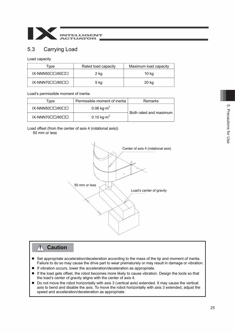
5.3 Carrying Load
Load capacity
Type Rated load capacity Maximum load capacity
IX-NNN50 /60 2 kg 10 kg
IX-NNN70 /80 5 kg 20 kg
Load’s permissible moment of inertia
Type Permissible moment of inertia Remarks
IX-NNN50 /60 0.06 kg m2
IX-NNN70 /80 0.10 kg m2Both rated and maximum
Load offset (from the center of axis 4 (rotational axis)) 50 mm or less
Set appropriate acceleration/deceleration according to the mass of the tip and moment of inertia. Failure to do so may cause the drive part to wear prematurely or may result in damage or vibration.
If vibration occurs, lower the acceleration/deceleration as appropriate. If the load gets offset, the robot becomes more likely to cause vibration. Design the tools so that
the load’s center of gravity aligns with the center of axis 4. Do not move the robot horizontally with axis 3 (vertical axis) extended. It may cause the vertical
axis to bend and disable the axis. To move the robot horizontally with axis 3 extended, adjust the speed and acceleration/deceleration as appropriate.
50 mm or less
Load’s center of gravity
Center of axis 4 (rotational axis)
26
5. P
reca
utio
ns fo
r Use
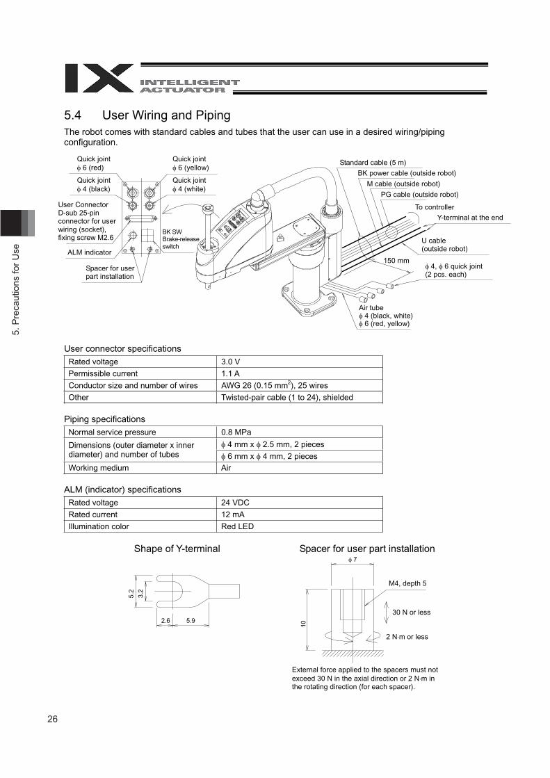
5.4 User Wiring and Piping The robot comes with standard cables and tubes that the user can use in a desired wiring/piping configuration.
User connector specifications Rated voltage 3.0 V
Permissible current 1.1 A
Conductor size and number of wires AWG 26 (0.15 mm2), 25 wires
Other Twisted-pair cable (1 to 24), shielded
Piping specifications Normal service pressure 0.8 MPa
4 mm x 2.5 mm, 2 pieces Dimensions (outer diameter x inner diameter) and number of tubes 6 mm x 4 mm, 2 pieces Working medium Air
ALM (indicator) specifications Rated voltage 24 VDC
Rated current 12 mA
Illumination color Red LED
Shape of Y-terminal Spacer for user part installation
User Connector D-sub 25-pin connector for user wiring (socket), fixing screw M2.6
ALM indicator
Spacer for user part installation
BK SW Brake-release switch
Standard cable (5 m)
BK power cable (outside robot)
M cable (outside robot)
PG cable (outside robot)
Y-terminal at the end To controller
Air tube 4 (black, white) 6 (red, yellow)
4, 6 quick joint (2 pcs. each)
U cable (outside robot)
M4, depth 5
30 N or less
External force applied to the spacers must not exceed 30 N in the axial direction or 2 N m in the rotating direction (for each spacer).
2 N m or less
Quick joint 6 (red)
Quick joint 4 (black)
Quick joint 6 (yellow)
Quick joint 4 (white)
150 mm
5.2
3.2
2.6 5.9
7
10
27
5. Precautions for U
se
Warning
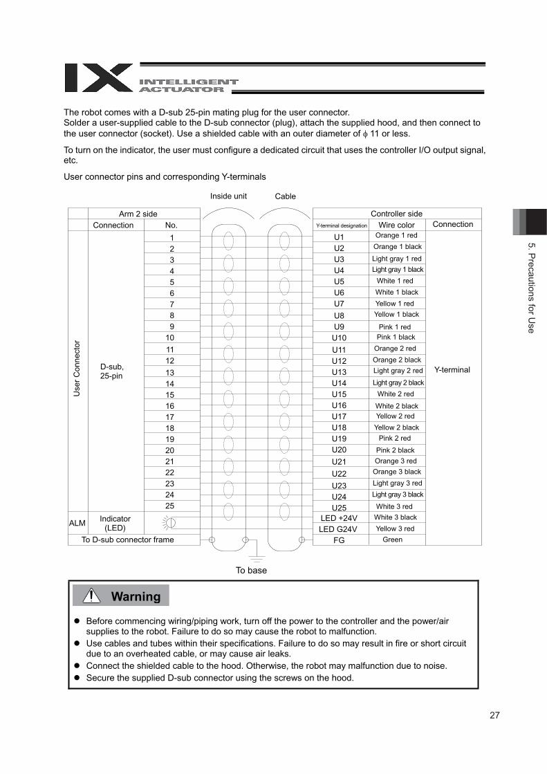
The robot comes with a D-sub 25-pin mating plug for the user connector. Solder a user-supplied cable to the D-sub connector (plug), attach the supplied hood, and then connect to the user connector (socket). Use a shielded cable with an outer diameter of 11 or less.
To turn on the indicator, the user must configure a dedicated circuit that uses the controller I/O output signal, etc.
User connector pins and corresponding Y-terminals
Before commencing wiring/piping work, turn off the power to the controller and the power/air supplies to the robot. Failure to do so may cause the robot to malfunction.
Use cables and tubes within their specifications. Failure to do so may result in fire or short circuit due to an overheated cable, or may cause air leaks.
Connect the shielded cable to the hood. Otherwise, the robot may malfunction due to noise. Secure the supplied D-sub connector using the screws on the hood.
To base
Inside unit Cable
Arm 2 side Connection
D-sub,25-pin
Indicator (LED)
To D-sub connector frame
Controller side Y-terminal designation Wire color
Orange 1 red
Light gray 1 red
Connection
Y-terminal
Orange 1 black
Light gray 1 black
White 1 red
White 1 black
Yellow 1 red
Yellow 1 black
Pink 1 red Pink 1 black
Orange 2 red
Orange 2 black
White 2 red
White 2 black Yellow 2 red
Yellow 2 black
Pink 2 red
Pink 2 black
Orange 3 red
Orange 3 black
Light gray 2 red
Light gray 2 black
Light gray 3 red
Light gray 3 black
White 3 red
White 3 black
Yellow 3 red
Green
No.
1 2 3 4 5 6 7 8 9 10
11 12
13 14 15 16 17 18 19 20 21 22 23 24 25
U1U2U3U4U5U6U7
U8U9U10
U11 U12 U13 U14 U15 U16 U17 U18 U19 U20
U21
U22
U23 U24 U25
LED +24V LED G24V
FG
Use
r C
onne
ctor
ALM
28
6. P
reca
utio
ns fo
r Use
Warning
6 Inspection/Maintenance
6.1 Inspection/Maintenance Your horizontal articulated robot must be inspected daily and on a regular basis to ensure safe, efficient operation. Perform the necessary inspections after confirming the maintenance/inspection items required for your IAI robot, as defined in this section.
Do not perform any inspection, adjustment or repair of the robot or controller, replacement of robot/controller part or any other operation not described in this operation manual. The following items must be adjusted at our factory. Do not disassemble the following components or cut cables at the user site:
Disassembly of servo motor Disassembly of ball speed reducer Disassembly of ball-screw spline Disassembly of bearing Disassembly of harmonic speed reducer Disassembly of brake Cutting of cable
IAI will not be responsible for any malfunction or damage resulting from the conduct of any operation cited above. Dpending on the periodic inspection item, the controller power may have to remain on or off. In either case, take proper measures to make sure other operators cannot operate the power.
Performing inspection or maintenance without fully understanding the details of work may result in a serious accident.
If inspections are neglected, the drive part may wear prematurely or the robot may malfunction unexpectedly.
29
6. Precautions for U
se
6.1.1 Daily InspectionCheck the following items daily before and after operating the robot.Observe the precautions for work near the robot and for inspection/maintenance/adjustment operationswhen carrying out each check.
Check location Description
Safety cage Correct the deformation or positional shift of the cage.Confirm that the interlock mechanism is operating properly.
Robot
Check the robot mounting bolts for looseness.Check the exterior for abnormality, loose covers, flaws, dents, etc.(If the robot has flaws or other abnormalities, please contact IAI.)Check for abnormal move, vibration or noise.
Cables Check the cables for flaws.Check the cable mounting parts for looseness.
Emergency-stop switch Confirm that the emergency-stop switch functions properly.
6.1.2 Six-Month InspectionCheck the following items on the robot every six months.Observe the precautions for work near the robot and for inspection/maintenance/adjustment operationswhen carrying out each check.
Check location Description
RobotCheck the arm mounting sections for looseness.(If any of the arm mounting sections is loose, tighten the fastening partssecurely.)
Ball-screw splineCheck the ball screw and spline for looseness.Wipe off old grease using a waste cloth, etc., and add new grease.(Standard specification: Multemp LRL No. 3 by Kyodo Yushi or equivalent)
Connectors Check the connectors for looseness.If the robot has flaws or other abnormalities, please contact IAI.
In case the grease got into your eye, immediately go to see the doctor to get an appropriate care.After finishing the grease supply work, wash your hands carefully with water and soap to rinse the grease off.
Caution
30
6. P
reca
utio
ns fo
r Use
Performing inspection or maintenance without fully understanding the details of work may result ina serious accident.Display a “Work in Progress” sign so that other operators will not operate the controller, operationpanel, etc.Use dedicated batteries for IX. Batteries for the old model (IH) cannot be used.
6.1.3 Yearly InspectionCheck the following items on the robot every year.Observe the precautions for work near the robot and for inspection/maintenance/adjustment operationswhen carrying out each check.
Check location DescriptionHarmonic reduction gears,joint bearings
Check arm 1 or 2 for looseness in the rotating direction or axial direction.(Contact IAI if an abnormality is found.)
Ball-screw spline Check the vertical axis for looseness.(Contact IAI if an abnormality is found.)
Performing inspection or maintenance without fully understanding the details of work may result in aserious accident.If inspections are neglected, the drive part may wear prematurely or the robot may malfunctionunexpectedly.Display a “Work in Progress” sign so that other operators will not operate the controller, operationpanel, etc.
6.2 Battery Replacement
6.2.1 PreparationThe following items are required when replacing the batteries:
Phillips screwdriverNew dedicated batteries for IX: AB-3 (4 pieces)
Before replacing the batteries, turn off the power to the controller, control panel and other relevant units.
Warning
Warning Caution
31
6. Precautions for U
se
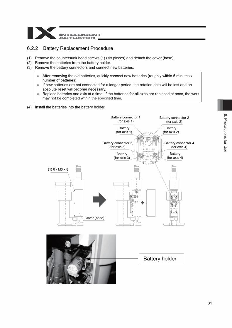
6.2.2 Battery Replacement Procedure
(1) Remove the countersunk head screws (1) (six pieces) and detach the cover (base). (2) Remove the batteries from the battery holder. (3) Remove the battery connectors and connect new batteries.
After removing the old batteries, quickly connect new batteries (roughly within 5 minutes x number of batteries).
If new batteries are not connected for a longer period, the rotation data will be lost and an absolute reset will become necessary.
Replace batteries one axis at a time. If the batteries for all axes are replaced at once, the work may not be completed within the specified time.
(4) Install the batteries into the battery holder.
Battery connector 1 (for axis 1)
Battery connector 2 (for axis 2)
Battery (for axis 1)
Battery (for axis 2)
Battery connector 4(for axis 4)
Battery (for axis 4)
Battery connector 3 (for axis 3)
Battery (for axis 3)
(1) 6 - M3 x 8
Cover (base)
Battery holder
32
6. P
reca
utio
ns fo
r Use
Caution
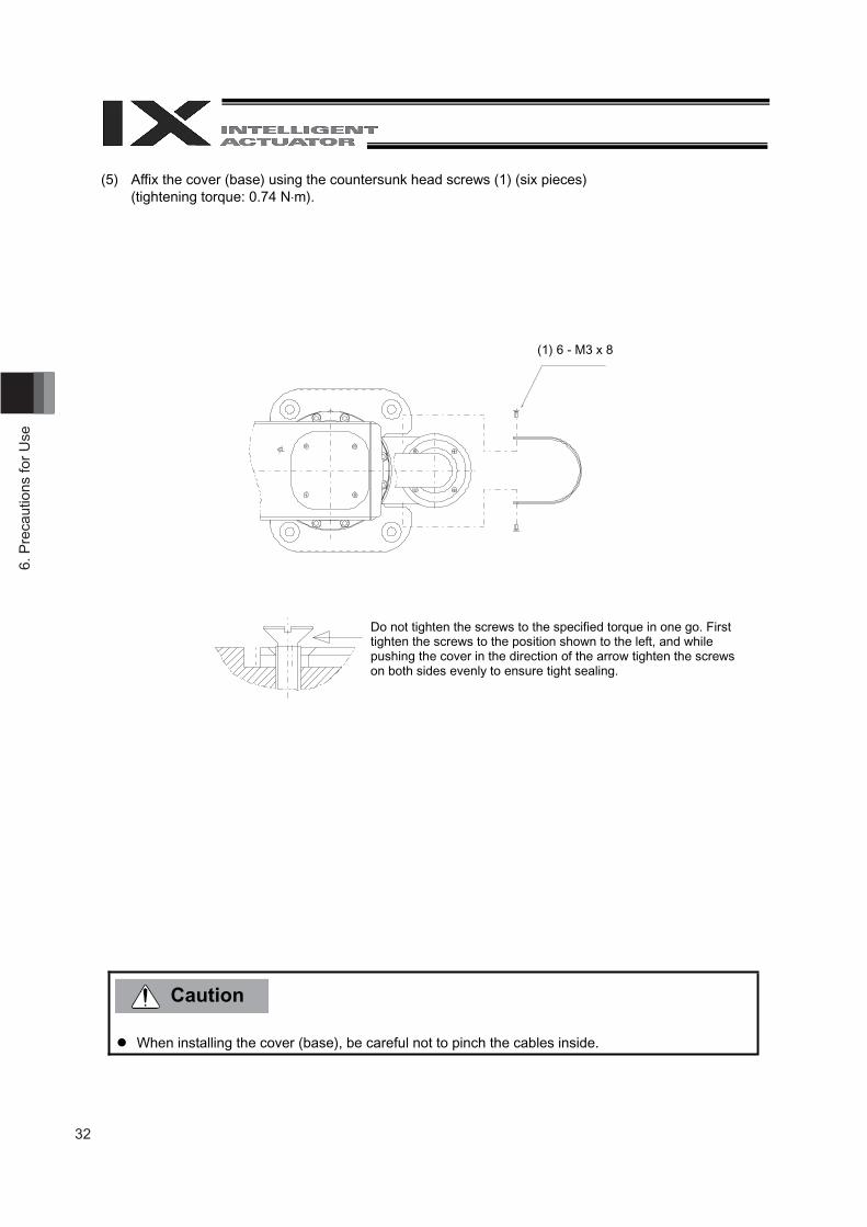
(5) Affix the cover (base) using the countersunk head screws (1) (six pieces) (tightening torque: 0.74 N m).
When installing the cover (base), be careful not to pinch the cables inside.
(1) 6 - M3 x 8
Do not tighten the screws to the specified torque in one go. First tighten the screws to the position shown to the left, and while pushing the cover in the direction of the arrow tighten the screws on both sides evenly to ensure tight sealing.
33
6. Precautions for U
se
6.3 Absolute Reset Procedure
The home of your actuator has been adjusted fully prior to its shipment from IAI. IX-NNN-50**/60**/70**/80** actuators adopt an absolute encoder, which means that their home is set by means of an absolute reset. The absolute data in the encoder is backed up using a battery, so once an absolute reset is performed, you need not repeat an absolute reset the next time the power is turned on. However, an absolute reset may be required after replacing the motor or when the encoder has lost its absolute data due to detection of low encoder battery voltage or for other reasons.
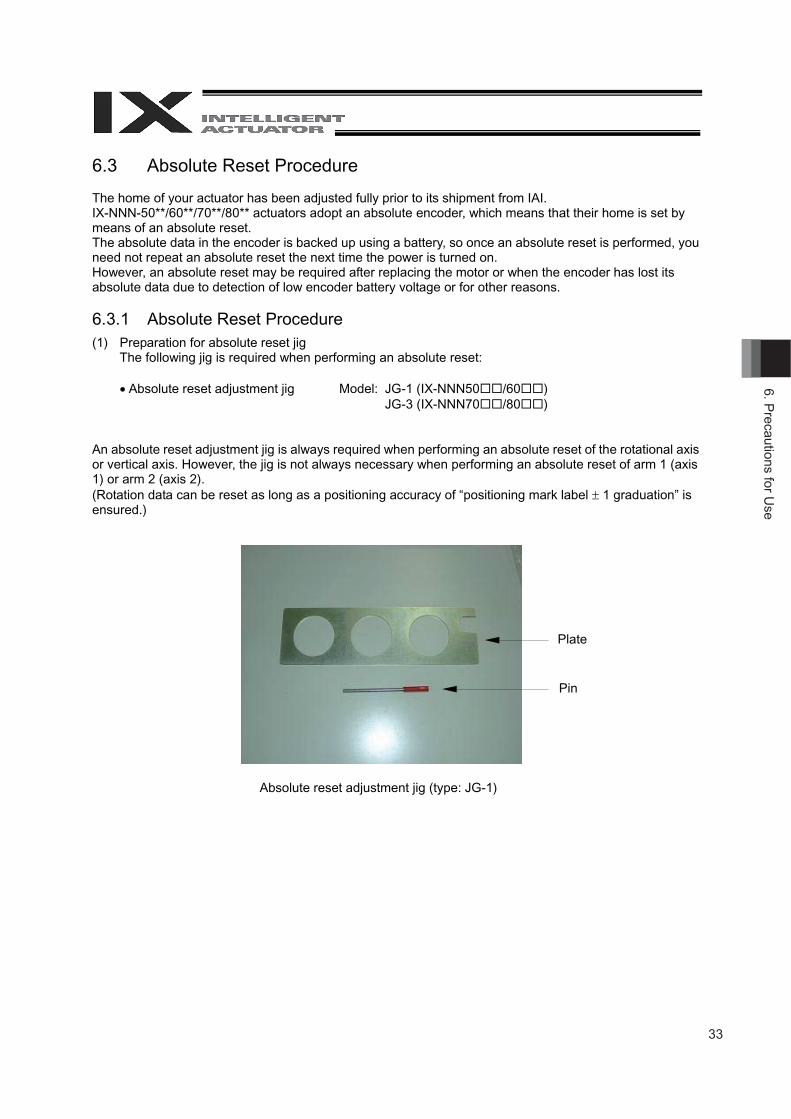
6.3.1 Absolute Reset Procedure (1) Preparation for absolute reset jig
The following jig is required when performing an absolute reset:
Absolute reset adjustment jig Model: JG-1 (IX-NNN50 /60 ) JG-3 (IX-NNN70 /80 )
An absolute reset adjustment jig is always required when performing an absolute reset of the rotational axis or vertical axis. However, the jig is not always necessary when performing an absolute reset of arm 1 (axis 1) or arm 2 (axis 2). (Rotation data can be reset as long as a positioning accuracy of “positioning mark label 1 graduation” is ensured.)
Plate
Pin
Absolute reset adjustment jig (type: JG-1)
34
6. P
reca
utio
ns fo
r Use
Warning
(2) Connect the cables for the robot, controller and PC, so the robot can be operated from the PC. Before commencing the work, always confirm that the emergency-stop switch is functioning properly.
(3) Back up the parameters. Be sure to back up the parameters before performing an absolute reset.
(4) Start the absolute reset menu. (5) Perform an absolute reset. (6) Perform a software reset.
Performing inspection or maintenance without fully understanding the details of work may result in a serious accident.
Display a “Work in Progress” sign so that other operators will not operate the controller, operation panel, etc.
Perform an absolute reset after backing up the parameters.
35
6. Precautions for U
se
6.3.2 Starting the Absolute Reset Menu
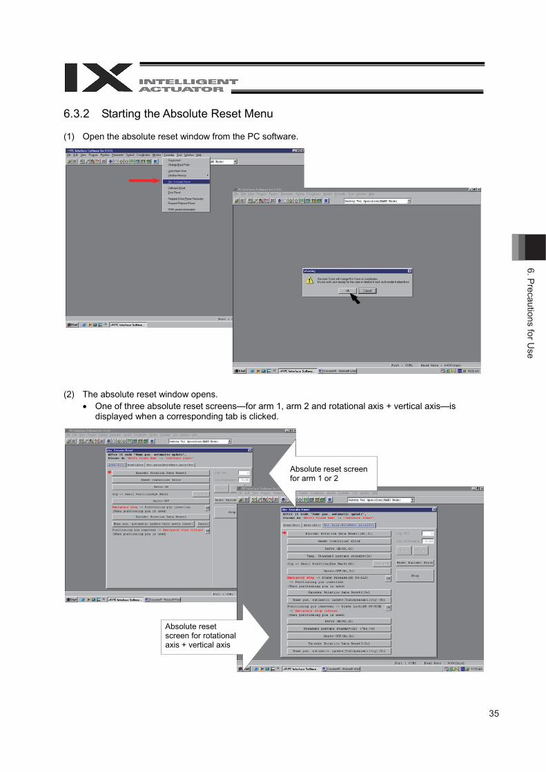
(1) Open the absolute reset window from the PC software.
(2) The absolute reset window opens. One of three absolute reset screens—for arm 1, arm 2 and rotational axis + vertical axis—is
displayed when a corresponding tab is clicked.
Absolute reset screen for arm 1 or 2
Absolute reset screen for rotational axis + vertical axis
36
6. P
reca
utio
ns fo
r Use
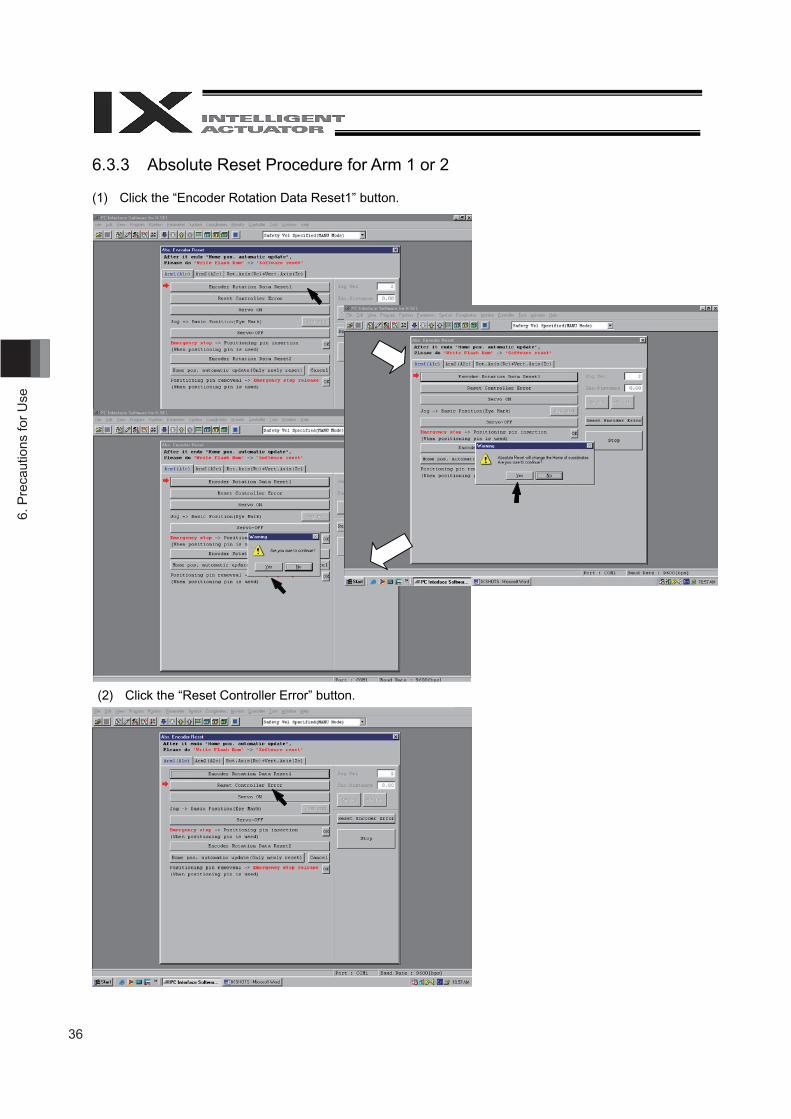
6.3.3 Absolute Reset Procedure for Arm 1 or 2
(1) Click the “Encoder Rotation Data Reset1” button.
(2) Click the “Reset Controller Error” button.

37
6. Precautions for U
se
(3) Click the “Servo ON” button.
(4) Jog the arm to near the reference position (see reference position drawing in step 7), and click the “Jog end” button.
(5) Click the “Servo-OFF” button.
38
6. P
reca
utio
ns fo
r Use
Warning
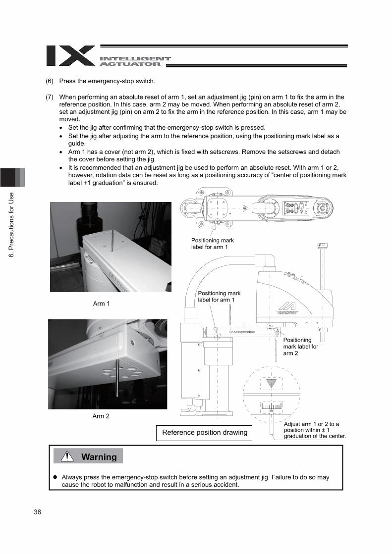
(6) Press the emergency-stop switch.
(7) When performing an absolute reset of arm 1, set an adjustment jig (pin) on arm 1 to fix the arm in the reference position. In this case, arm 2 may be moved. When performing an absolute reset of arm 2, set an adjustment jig (pin) on arm 2 to fix the arm in the reference position. In this case, arm 1 may be moved. Set the jig after confirming that the emergency-stop switch is pressed. Set the jig after adjusting the arm to the reference position, using the positioning mark label as a
guide. Arm 1 has a cover (not arm 2), which is fixed with setscrews. Remove the setscrews and detach
the cover before setting the jig. It is recommended that an adjustment jig be used to perform an absolute reset. With arm 1 or 2,
however, rotation data can be reset as long as a positioning accuracy of “center of positioning mark label 1 graduation” is ensured.
Always press the emergency-stop switch before setting an adjustment jig. Failure to do so may cause the robot to malfunction and result in a serious accident.
Positioning mark label for arm 1
Positioning mark label for arm 1
Positioning mark label for arm 2
Adjust arm 1 or 2 to a position within ± 1 graduation of the center. Reference position drawing
Arm 1
Arm 2
39
6. Precautions for U
se
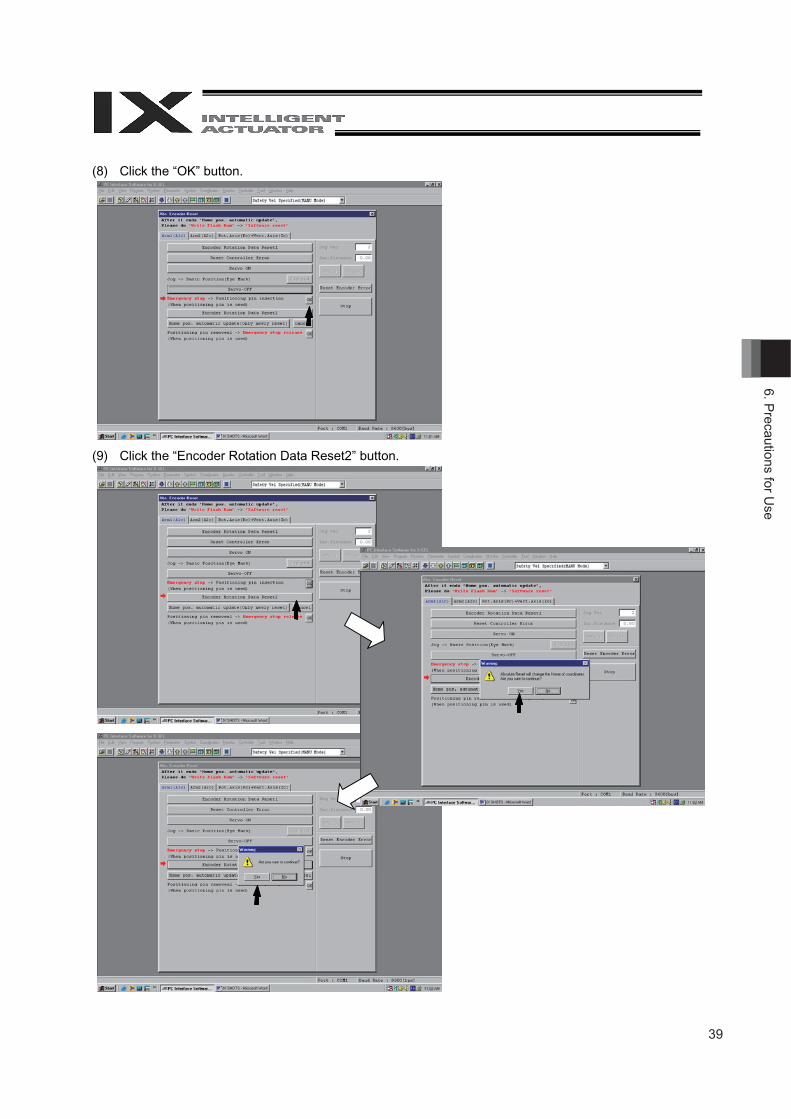
(8) Click the “OK” button.
(9) Click the “Encoder Rotation Data Reset2” button.
40
6. P
reca
utio
ns fo
r Use
Caution
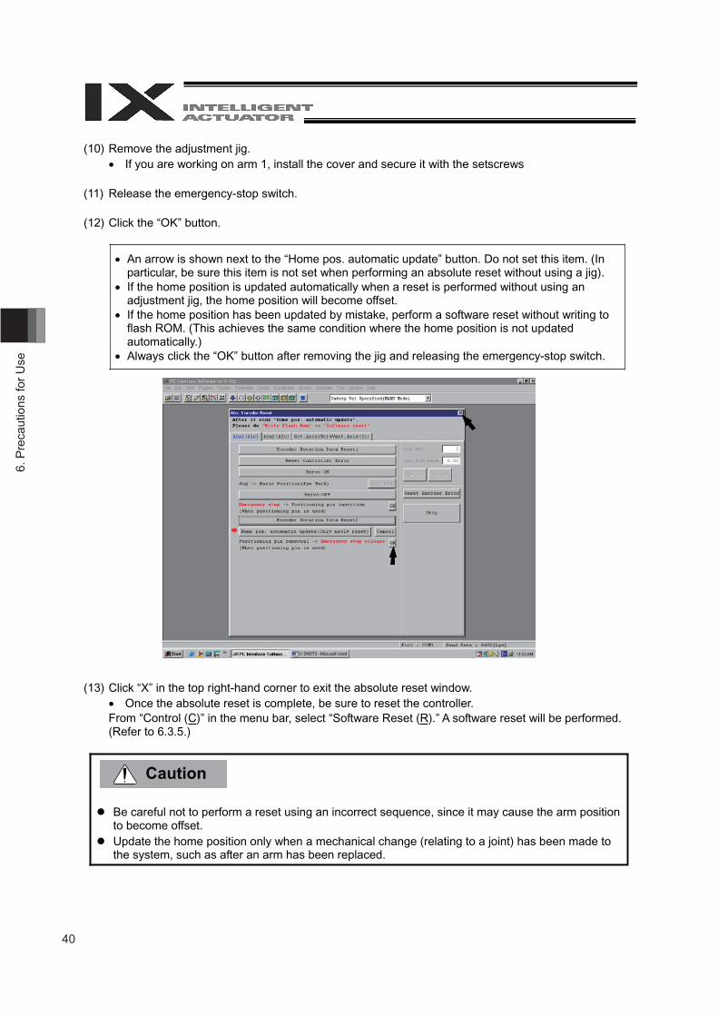
(10) Remove the adjustment jig. If you are working on arm 1, install the cover and secure it with the setscrews
(11) Release the emergency-stop switch.
(12) Click the “OK” button.
An arrow is shown next to the “Home pos. automatic update” button. Do not set this item. (In particular, be sure this item is not set when performing an absolute reset without using a jig).
If the home position is updated automatically when a reset is performed without using an adjustment jig, the home position will become offset.
If the home position has been updated by mistake, perform a software reset without writing to flash ROM. (This achieves the same condition where the home position is not updated automatically.)
Always click the “OK” button after removing the jig and releasing the emergency-stop switch.
(13) Click “X” in the top right-hand corner to exit the absolute reset window. Once the absolute reset is complete, be sure to reset the controller.
From “Control (C)” in the menu bar, select “Software Reset (R).” A software reset will be performed. (Refer to 6.3.5.)
Be careful not to perform a reset using an incorrect sequence, since it may cause the arm position to become offset.
Update the home position only when a mechanical change (relating to a joint) has been made to the system, such as after an arm has been replaced.
41
6. Precautions for U
se
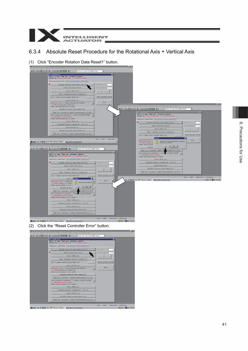
6.3.4 Absolute Reset Procedure for the Rotational Axis + Vertical Axis
(1) Click “Encoder Rotation Data Reset1” button.
(2) Click the “Reset Controller Error” button.
42
6. P
reca
utio
ns fo
r Use
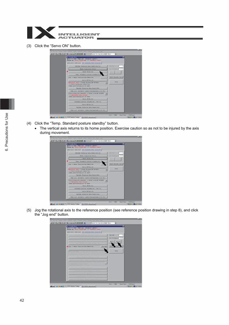
(3) Click the “Servo ON” button.
(4) Click the “Temp. Standard posture standby” button. The vertical axis returns to its home position. Exercise caution so as not to be injured by the axis
during movement.
(5) Jog the rotational axis to the reference position (see reference position drawing in step 8), and click the “Jog end” button.
43
6. Precautions for U
se
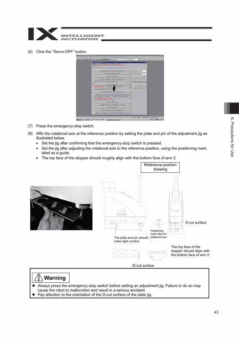
(6) Click the “Servo-OFF” button.
(7) Press the emergency-stop switch.
(8) Affix the rotational axis at the reference position by setting the plate and pin of the adjustment jig as illustrated below. Set the jig after confirming that the emergency-stop switch is pressed. Set the jig after adjusting the rotational axis to the reference position, using the positioning mark
label as a guide. The top face of the stopper should roughly align with the bottom face of arm 2.
Always press the emergency-stop switch before setting an adjustment jig. Failure to do so may cause the robot to malfunction and result in a serious accident.
Pay attention to the orientation of the D-cut surface of the plate jig.
Reference position drawing
D-cut surface
D-cut surface
The plate and pin should make light contact.
Positioning mark label for rotational axis
The top face of the stopper should align with the bottom face of arm 2.
Warning
44
6. P
reca
utio
ns fo
r Use
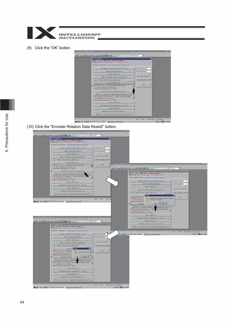
(9) Click the “OK” button.
(10) Click the “Encoder Rotation Data Reset2” button.
45
6. Precautions for U
se
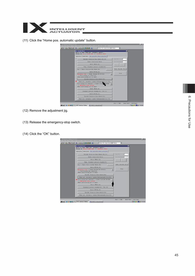
(11) Click the “Home pos. automatic update” button.
(12) Remove the adjustment jig.
(13) Release the emergency-stop switch.
(14) Click the “OK” button.
46
6. P
reca
utio
ns fo
r Use
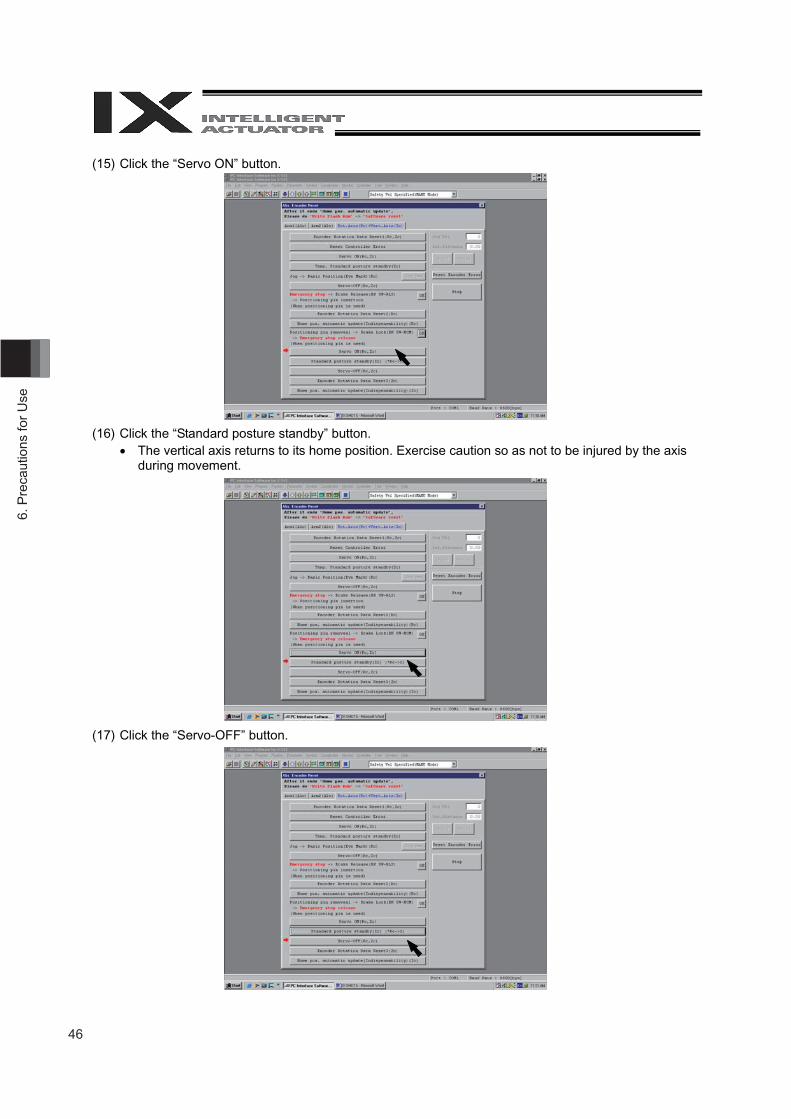
(15) Click the “Servo ON” button.
(16) Click the “Standard posture standby” button. The vertical axis returns to its home position. Exercise caution so as not to be injured by the axis
during movement.
(17) Click the “Servo-OFF” button.
47
6. Precautions for U
se
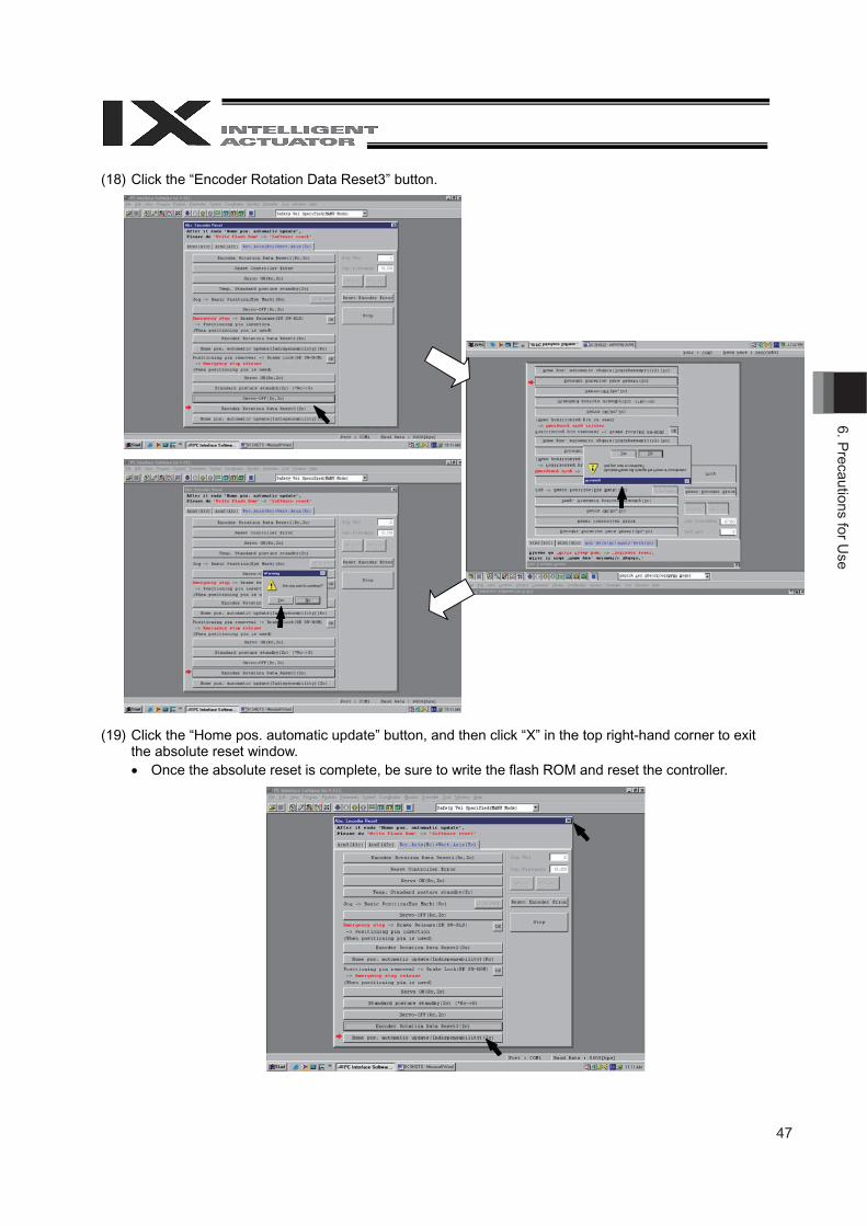
(18) Click the “Encoder Rotation Data Reset3” button.
(19) Click the “Home pos. automatic update” button, and then click “X” in the top right-hand corner to exit the absolute reset window. Once the absolute reset is complete, be sure to write the flash ROM and reset the controller.
48
6. P
reca
utio
ns fo
r Use
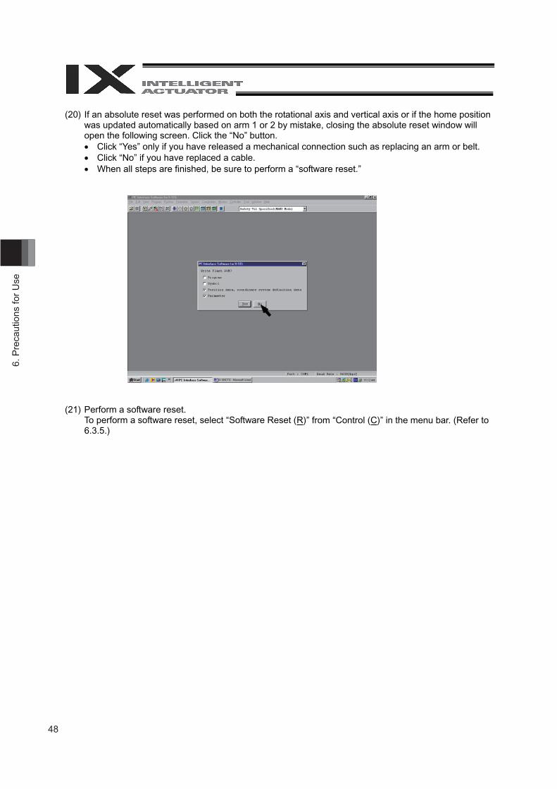
(20) If an absolute reset was performed on both the rotational axis and vertical axis or if the home position was updated automatically based on arm 1 or 2 by mistake, closing the absolute reset window will open the following screen. Click the “No” button. Click “Yes” only if you have released a mechanical connection such as replacing an arm or belt. Click “No” if you have replaced a cable. When all steps are finished, be sure to perform a “software reset.”
(21) Perform a software reset. To perform a software reset, select “Software Reset (R)” from “Control (C)” in the menu bar. (Refer to 6.3.5.)
49
6. Precautions for U
se
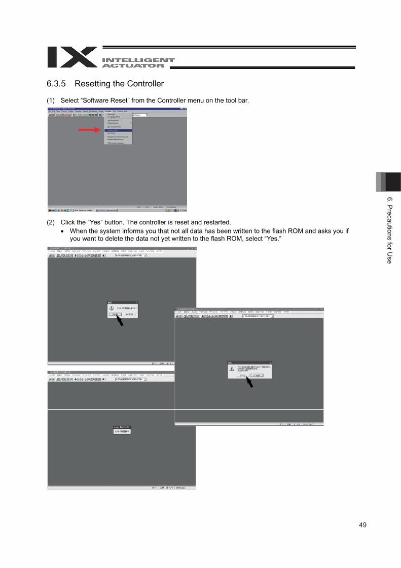
6.3.5 Resetting the Controller
(1) Select “Software Reset” from the Controller menu on the tool bar.
(2) Click the “Yes” button. The controller is reset and restarted. When the system informs you that not all data has been written to the flash ROM and asks you if
you want to delete the data not yet written to the flash ROM, select “Yes.”
50
7. S
peci
fi cat
ions
7 Specifications
7.1 Specification Table
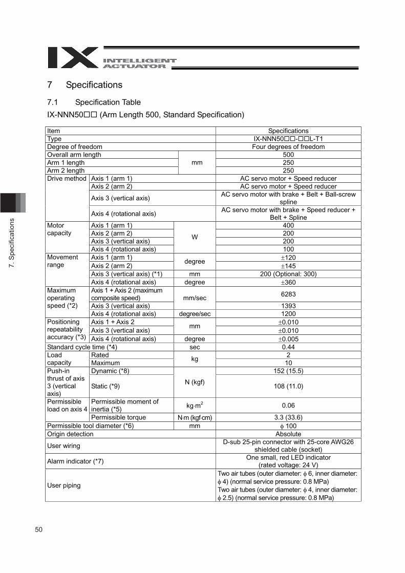
IX-NNN50 (Arm Length 500, Standard Specification)
Item Specifications Type IX-NNN50 - L-T1 Degree of freedom Four degrees of freedom Overall arm length 500 Arm 1 length 250 Arm 2 length
mm 250
Axis 1 (arm 1) AC servo motor + Speed reducer Axis 2 (arm 2) AC servo motor + Speed reducer
Axis 3 (vertical axis) AC servo motor with brake + Belt + Ball-screw spline
Drive method
Axis 4 (rotational axis) AC servo motor with brake + Speed reducer + Belt + Spline
Axis 1 (arm 1) 400Axis 2 (arm 2) 200Axis 3 (vertical axis) 200
Motor capacity
Axis 4 (rotational axis)
W
100 Axis 1 (arm 1) 120 Axis 2 (arm 2)
degree 145
Axis 3 (vertical axis) (*1) mm 200 (Optional: 300)
Movement range
Axis 4 (rotational axis) degree 360 Axis 1 + Axis 2 (maximum composite speed) 6283
Axis 3 (vertical axis) mm/sec
1393
Maximum operating speed (*2)
Axis 4 (rotational axis) degree/sec 1200Axis 1 + Axis 2 0.010 Axis 3 (vertical axis)
mm0.010
Positioning repeatability accuracy (*3) Axis 4 (rotational axis) degree 0.005 Standard cycle time (*4) sec 0.44
Rated 2 Load capacity Maximum
kg 10
Dynamic (*8) 152 (15.5) Push-in thrust of axis 3 (vertical axis)
Static (*9) N (kgf)
108 (11.0)
Permissible moment of inertia (*5) kg m2 0.06 Permissible
load on axis 4 Permissible torque N m (kgf cm) 3.3 (33.6)
Permissible tool diameter (*6) mm 100 Origin detection Absolute
User wiring D-sub 25-pin connector with 25-core AWG26 shielded cable (socket)
Alarm indicator (*7) One small, red LED indicator (rated voltage: 24 V)
User piping
Two air tubes (outer diameter: 6, inner diameter: 4) (normal service pressure: 0.8 MPa)
Two air tubes (outer diameter: 4, inner diameter: 2.5) (normal service pressure: 0.8 MPa)
51
7. Specifi cations
snoitacificepSmetI
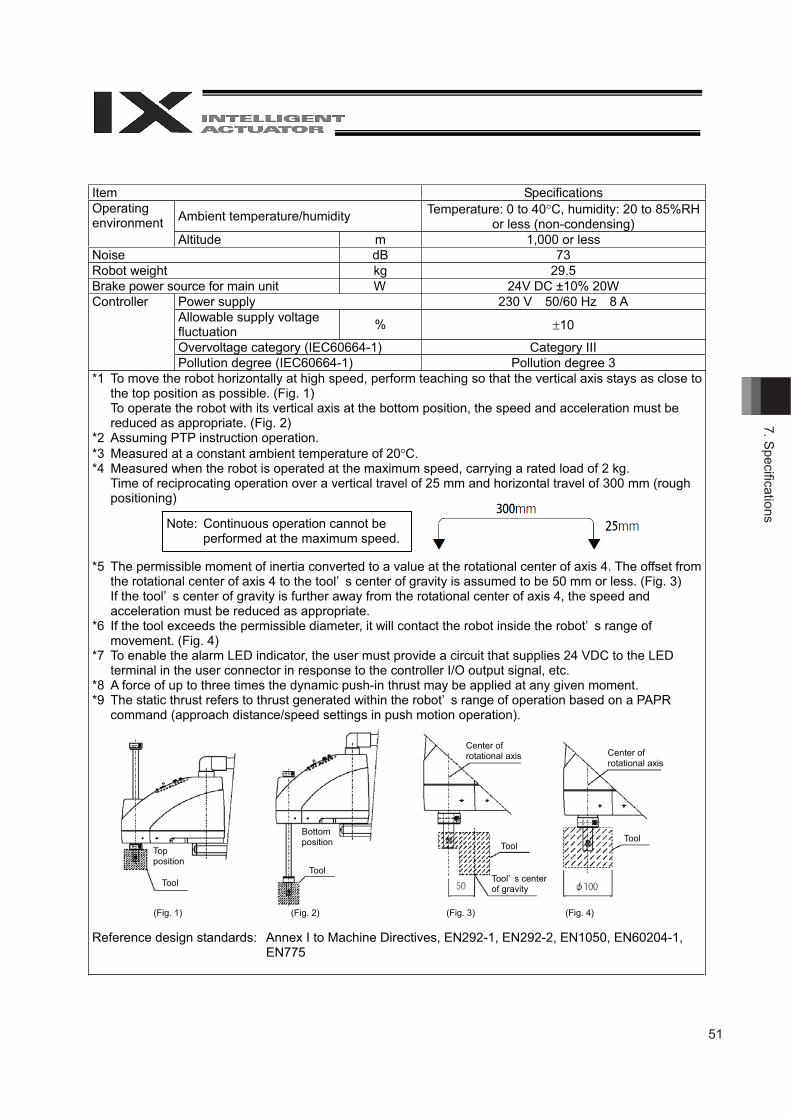
Ambient temperature/humidity Temperature: 0 to 40 C, humidity: 20 to 85%RHor less (non-condensing)
Operatingenvironment
000,1medutitlA or lessBdesioN 73
Power supply 230 V 50/60 Hz 8 AAllowable supply voltagefluctuation % 10
Overvoltage category (IEC60664-1) Category III
Controller
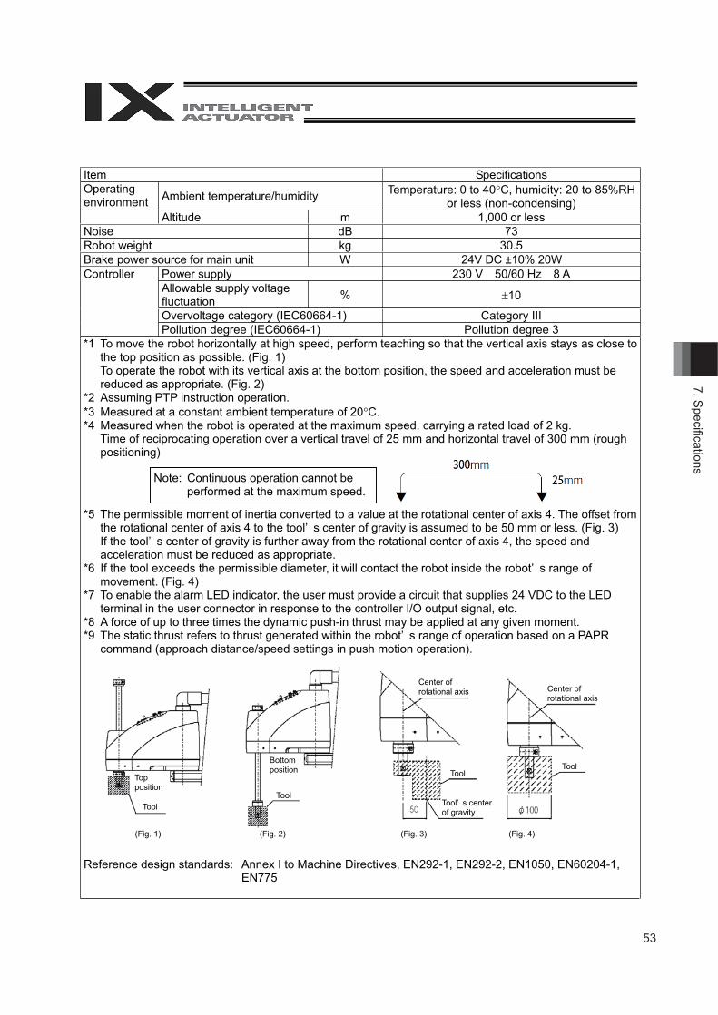
Pollution degree (IEC60664-1) Pollution degree 3*1 To move the robot horizontally at high speed, perform teaching so that the vertical axis stays as close to
the top position as possible. (Fig. 1)To operate the robot with its vertical axis at the bottom position, the speed and acceleration must bereduced as appropriate. (Fig. 2)
*2 Assuming PTP instruction operation.*3 Measured at a constant ambient temperature of 20 C.*4 Measured when the robot is operated at the maximum speed, carrying a rated load of 2 kg.
Time of reciprocating operation over a vertical travel of 25 mm and horizontal travel of 300 mm (roughpositioning)
*5 The permissible moment of inertia converted to a value at the rotational center of axis 4. The offset fromthe rotational center of axis 4 to the tool’ s center of gravity is assumed to be 50 mm or less. (Fig. 3)If the tool’ s center of gravity is further away from the rotational center of axis 4, the speed andacceleration must be reduced as appropriate.
*6 If the tool exceeds the permissible diameter, it will contact the robot inside the robot’ s range ofmovement. (Fig. 4)
*7 To enable the alarm LED indicator, the user must provide a circuit that supplies 24 VDC to the LEDterminal in the user connector in response to the controller I/O output signal, etc.
*8 A force of up to three times the dynamic push-in thrust may be applied at any given moment.*9 The static thrust refers to thrust generated within the robot’ s range of operation based on a PAPR
command (approach distance/speed settings in push motion operation).
Reference design standards: Annex I to Machine Directives, EN292-1, EN292-2, EN1050, EN60204-1,EN775
Topposition
ToolTool
ToolTool
Bottomposition
Center ofrotational axis Center of
rotational axis
Tool’ s centerof gravity
(Fig. 1) (Fig. 2) (Fig. 3) (Fig. 4)
Note: Continuous operation cannot beperformed at the maximum speed.
Brake power source for main unitRobot weight
Wkg
24V DC ±10% 20W29.5
52
7. S
peci
fi cat
ions
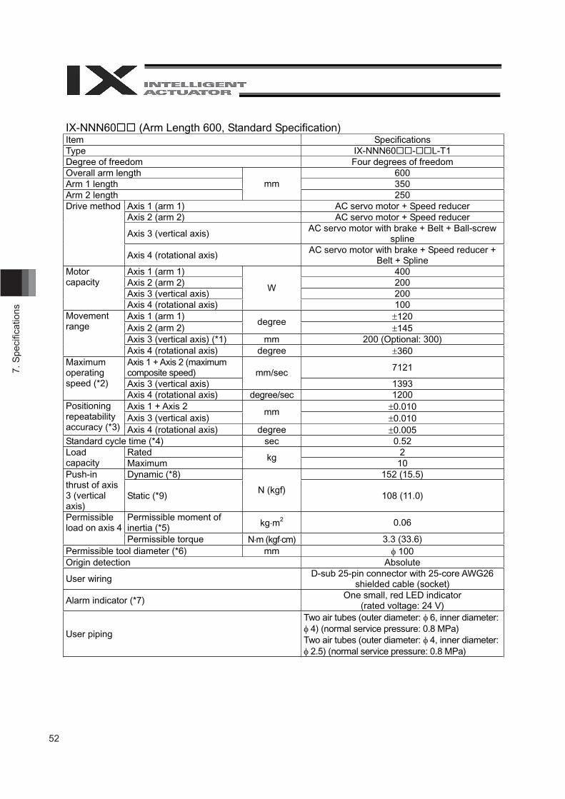
IX-NNN60 (Arm Length 600, Standard Specification) Item Specifications Type IX-NNN60 - L-T1 Degree of freedom Four degrees of freedom Overall arm length 600 Arm 1 length 350 Arm 2 length
mm250
Axis 1 (arm 1) AC servo motor + Speed reducer Axis 2 (arm 2) AC servo motor + Speed reducer
Axis 3 (vertical axis) AC servo motor with brake + Belt + Ball-screw spline
Drive method
Axis 4 (rotational axis) AC servo motor with brake + Speed reducer + Belt + Spline
Axis 1 (arm 1) 400Axis 2 (arm 2) 200Axis 3 (vertical axis) 200
Motor capacity
Axis 4 (rotational axis)
W
100 Axis 1 (arm 1) 120 Axis 2 (arm 2)
degree 145
Axis 3 (vertical axis) (*1) mm 200 (Optional: 300)
Movement range
Axis 4 (rotational axis) degree 360 Axis 1 + Axis 2 (maximum composite speed) 7121
Axis 3 (vertical axis) mm/sec
1393
Maximum operating speed (*2)
Axis 4 (rotational axis) degree/sec 1200Axis 1 + Axis 2 0.010 Axis 3 (vertical axis)
mm0.010
Positioning repeatability accuracy (*3) Axis 4 (rotational axis) degree 0.005 Standard cycle time (*4) sec 0.52
Rated 2 Load capacity Maximum
kg 10
Dynamic (*8) 152 (15.5) Push-in thrust of axis 3 (vertical axis)
Static (*9) N (kgf)
108 (11.0)
Permissible moment of inertia (*5) kg m2 0.06 Permissible
load on axis 4 Permissible torque N m (kgf cm) 3.3 (33.6)
Permissible tool diameter (*6) mm 100 Origin detection Absolute
User wiring D-sub 25-pin connector with 25-core AWG26 shielded cable (socket)
Alarm indicator (*7) One small, red LED indicator (rated voltage: 24 V)
User piping
Two air tubes (outer diameter: 6, inner diameter: 4) (normal service pressure: 0.8 MPa)
Two air tubes (outer diameter: 4, inner diameter: 2.5) (normal service pressure: 0.8 MPa)
53
7. Specifi cations
snoitacificepSmetI
Ambient temperature/humidity Temperature: 0 to 40 C, humidity: 20 to 85%RHor less (non-condensing)
Operatingenvironment
000,1medutitlA or lessBdesioN 73
Robot weight kg 30.5
Power supply 230 V 50/60 Hz 8 AAllowable supply voltagefluctuation % 10
Overvoltage category (IEC60664-1) Category III
Controller
Pollution degree (IEC60664-1) Pollution degree 3*1 To move the robot horizontally at high speed, perform teaching so that the vertical axis stays as close to
the top position as possible. (Fig. 1)To operate the robot with its vertical axis at the bottom position, the speed and acceleration must bereduced as appropriate. (Fig. 2)
*2 Assuming PTP instruction operation.*3 Measured at a constant ambient temperature of 20 C.*4 Measured when the robot is operated at the maximum speed, carrying a rated load of 2 kg.
Time of reciprocating operation over a vertical travel of 25 mm and horizontal travel of 300 mm (roughpositioning)
*5 The permissible moment of inertia converted to a value at the rotational center of axis 4. The offset fromthe rotational center of axis 4 to the tool’ s center of gravity is assumed to be 50 mm or less. (Fig. 3)If the tool’ s center of gravity is further away from the rotational center of axis 4, the speed andacceleration must be reduced as appropriate.
*6 If the tool exceeds the permissible diameter, it will contact the robot inside the robot’ s range ofmovement. (Fig. 4)
*7 To enable the alarm LED indicator, the user must provide a circuit that supplies 24 VDC to the LEDterminal in the user connector in response to the controller I/O output signal, etc.
*8 A force of up to three times the dynamic push-in thrust may be applied at any given moment.*9 The static thrust refers to thrust generated within the robot’ s range of operation based on a PAPR
command (approach distance/speed settings in push motion operation).
Reference design standards: Annex I to Machine Directives, EN292-1, EN292-2, EN1050, EN60204-1,EN775
Note: Continuous operation cannot beperformed at the maximum speed.
Topposition
ToolTool
ToolTool
Bottomposition
Center ofrotational axis Center of
rotational axis
Tool’ s centerof gravity
(Fig. 1) (Fig. 2) (Fig. 3) (Fig. 4)
Brake power source for main unit W 24V DC ±10% 20W
54
7. S
peci
fi cat
ions
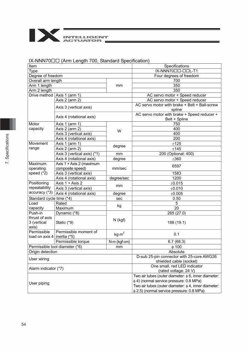
IX-NNN70 (Arm Length 700, Standard Specification) Item Specifications Type IX-NNN70 - L-T1 Degree of freedom Four degrees of freedom Overall arm length 700 Arm 1 length 350 Arm 2 length
mm350
Axis 1 (arm 1) AC servo motor + Speed reducer Axis 2 (arm 2) AC servo motor + Speed reducer
Axis 3 (vertical axis) AC servo motor with brake + Belt + Ball-screw spline
Drive method
Axis 4 (rotational axis) AC servo motor with brake + Speed reducer + Belt + Spline
Axis 1 (arm 1) 750Axis 2 (arm 2) 400Axis 3 (vertical axis) 400
Motor capacity
Axis 4 (rotational axis)
W
200 Axis 1 (arm 1) 125 Axis 2 (arm 2)
degree 145
Axis 3 (vertical axis) (*1) mm 200 (Optional: 400)
Movement range
Axis 4 (rotational axis) degree 360 Axis 1 + Axis 2 (maximum composite speed) 6597
Axis 3 (vertical axis) mm/sec
1583
Maximum operating speed (*2)
Axis 4 (rotational axis) degree/sec 1200Axis 1 + Axis 2 0.015 Axis 3 (vertical axis)
mm0.010
Positioning repeatability accuracy (*3) Axis 4 (rotational axis) degree 0.005 Standard cycle time (*4) sec 0.50
Rated 5 Load capacity Maximum
kg 20
Dynamic (*8) 265 (27.0) Push-in thrust of axis 3 (vertical axis)
Static (*9) N (kgf)
188 (19.1)
Permissible moment of inertia (*5) kg m2 0.1Permissible
load on axis 4 Permissible torque N m (kgf cm) 6.7 (68.3)
Permissible tool diameter (*6) mm 100 Origin detection Absolute
User wiring D-sub 25-pin connector with 25-core AWG26 shielded cable (socket)
Alarm indicator (*7) One small, red LED indicator (rated voltage: 24 V)
User piping
Two air tubes (outer diameter: 6, inner diameter: 4) (normal service pressure: 0.8 MPa)
Two air tubes (outer diameter: 4, inner diameter: 2.5) (normal service pressure: 0.8 MPa)

55
7. Specifi cations
snoitacificepSmetI
Ambient temperature/humidity Temperature: 0 to 40 C, humidity: 20 to 85%RHor less (non-condensing)
Operatingenvironment
000,1medutitlA or lessBdesioN 74
Robot weight kg 58
Power supply 230 V 50/60 Hz 15 AAllowable supply voltagefluctuation % 10
Overvoltage category (IEC60664-1) Category III
Controller
Pollution degree (IEC60664-1) Pollution degree 3*1 To move the robot horizontally at high speed, perform teaching so that the vertical axis stays as close to
the top position as possible. (Fig. 1)To operate the robot with its vertical axis at the bottom position, the speed and acceleration must bereduced as appropriate. (Fig. 2)
*2 Assuming PTP instruction operation.*3 Measured at a constant ambient temperature of 20 C.*4 Measured when the robot is operated at the maximum speed, carrying a rated load of 5 kg.
Time of reciprocating operation over a vertical travel of 25 mm and horizontal travel of 300 mm (roughpositioning)
*5 The permissible moment of inertia converted to a value at the rotational center of axis 4. The offset fromthe rotational center of axis 4 to the tool’ s center of gravity is assumed to be 50 mm or less. (Fig. 3)If the tool’ s center of gravity is further away from the rotational center of axis 4, the speed andacceleration must be reduced as appropriate.
*6 If the tool exceeds the permissible diameter, it will contact the robot inside the robot’ s range ofmovement. (Fig. 4)
*7 To enable the alarm LED indicator, the user must provide a circuit that supplies 24 VDC to the LEDterminal in the user connector in response to the controller I/O output signal, etc.
*8 A force of up to three times the dynamic push-in thrust may be applied at any given moment.*9 The static thrust refers to thrust generated within the robot’ s range of operation based on a PAPR
command (approach distance/speed settings in push motion operation).
Reference design standards: Annex I to Machine Directives, EN292-1, EN292-2, EN1050, EN60204-1,EN775
Note: Continuous operation cannot beperformed at the maximum speed.
Topposition
ToolTool
ToolTool
Bottomposition
Center ofrotational axis Center of
rotational axis
Tool’ s centerof gravity
(Fig. 1) (Fig. 2) (Fig. 3) (Fig. 4)
Brake power source for main unit W 24V DC ±10% 20W
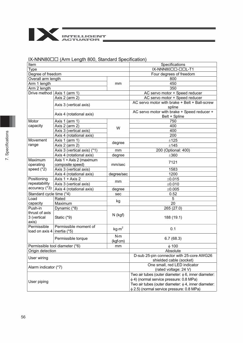
56
7. S
peci
fi cat
ions
IX-NNN80 (Arm Length 800, Standard Specification) Item Specifications Type IX-NNN80 - L-T1 Degree of freedom Four degrees of freedom Overall arm length 800 Arm 1 length 450 Arm 2 length
mm 350
Axis 1 (arm 1) AC servo motor + Speed reducer Axis 2 (arm 2) AC servo motor + Speed reducer
Axis 3 (vertical axis) AC servo motor with brake + Belt + Ball-screw spline
Drive method
Axis 4 (rotational axis) AC servo motor with brake + Speed reducer + Belt + Spline
Axis 1 (arm 1) 750Axis 2 (arm 2) 400Axis 3 (vertical axis) 400
Motor capacity
Axis 4 (rotational axis)
W
200 Axis 1 (arm 1) 125 Axis 2 (arm 2)
degree 145
Axis 3 (vertical axis) (*1) mm 200 (Optional: 400)
Movement range
Axis 4 (rotational axis) degree 360 Axis 1 + Axis 2 (maximum composite speed) 7121
Axis 3 (vertical axis) mm/sec
1583
Maximum operating speed (*2)
Axis 4 (rotational axis) degree/sec 1200Axis 1 + Axis 2 0.015 Axis 3 (vertical axis)
mm 0.010
Positioning repeatability accuracy (*3) Axis 4 (rotational axis) degree 0.005 Standard cycle time (*4) sec 0.52
Rated 5 Load capacity Maximum
kg20
Dynamic (*8) 265 (27.0) Push-in thrust of axis 3 (vertical axis)
Static (*9) N (kgf)
188 (19.1)
Permissible moment of inertia (*5) kg m2 0.1Permissible
load on axis 4
Permissible torque N m(kgf cm)
6.7 (68.3)
Permissible tool diameter (*6) mm 100 Origin detection Absolute
User wiring D-sub 25-pin connector with 25-core AWG26 shielded cable (socket)
Alarm indicator (*7) One small, red LED indicator (rated voltage: 24 V)
User piping
Two air tubes (outer diameter: 6, inner diameter: 4) (normal service pressure: 0.8 MPa)
Two air tubes (outer diameter: 4, inner diameter: 2.5) (normal service pressure: 0.8 MPa)
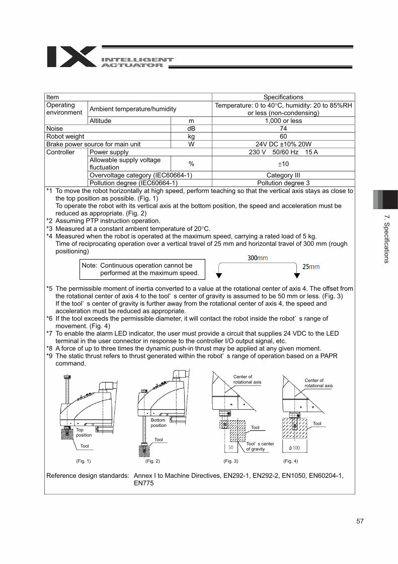
57
7. Specifi cations
snoitacificepSmetI
Ambient temperature/humidity Temperature: 0 to 40 C, humidity: 20 to 85%RHor less (non-condensing)
Operatingenvironment
000,1medutitlA or lessBdesioN 74
Robot weight kg 60
Power supply 230 V 50/60 Hz 15 AAllowable supply voltagefluctuation % 10
Overvoltage category (IEC60664-1) Category III
Controller
Pollution degree (IEC60664-1) Pollution degree 3*1 To move the robot horizontally at high speed, perform teaching so that the vertical axis stays as close to
the top position as possible. (Fig. 1)To operate the robot with its vertical axis at the bottom position, the speed and acceleration must bereduced as appropriate. (Fig. 2)
*2 Assuming PTP instruction operation.*3 Measured at a constant ambient temperature of 20 C.*4 Measured when the robot is operated at the maximum speed, carrying a rated load of 5 kg.
Time of reciprocating operation over a vertical travel of 25 mm and horizontal travel of 300 mm (roughpositioning)
*5 The permissible moment of inertia converted to a value at the rotational center of axis 4. The offset fromthe rotational center of axis 4 to the tool’ s center of gravity is assumed to be 50 mm or less. (Fig. 3)If the tool’ s center of gravity is further away from the rotational center of axis 4, the speed andacceleration must be reduced as appropriate.
*6 If the tool exceeds the permissible diameter, it will contact the robot inside the robot’ s range ofmovement. (Fig. 4)
*7 To enable the alarm LED indicator, the user must provide a circuit that supplies 24 VDC to the LEDterminal in the user connector in response to the controller I/O output signal, etc.
*8 A force of up to three times the dynamic push-in thrust may be applied at any given moment.*9 The static thrust refers to thrust generated within the robot’ s range of operation based on a PAPR
command.
Reference design standards: Annex I to Machine Directives, EN292-1, EN292-2, EN1050, EN60204-1,EN775
Note: Continuous operation cannot beperformed at the maximum speed.
Topposition
ToolTool
ToolTool
Bottomposition
Center ofrotational axis Center of
rotational axis
Tool’ s centerof gravity
(Fig. 1) (Fig. 2) (Fig. 3) (Fig. 4)
Brake power source for main unit W 24V DC ±10% 20W
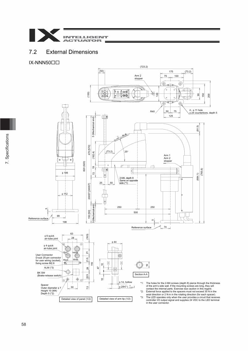
58
7. S
peci
fi cat
ions
7.2 External Dimensions
IX-NNN50
Arm 2 stopper
4 - 11 hole 24 counterbore, depth 5
5 (M
echa
nica
l end
)
2-M4, depth 8Same on opposite side (*1)
5 (M
echa
nica
l end
)
Arm 1 Arm 2 stopper
6 quick air-tube joint
4 quick air-tube joint
User Connector D-sub 25-pin connector for user wiring (socket), fixing screw M2.6
ALM (*3)
BK SW (Brake-release switch)
Spacer Outer diameter 7 Height 10 (M4) Depth 5 (*2)
Detailed view of panel (1/2) Detailed view of arm tip (1/2)
14, hollow
Section A-A
*1: The holes for the 2-M4 screws (depth 8) pierce through the thickness of the arm’s side wall. If the mounting screws are long, they will contact the internal parts. Exercise due caution in this regard.
*2: External force applied to the spacers must not exceed 30 N in the axial direction or 2 N m in the rotating direction (for each spacer).
*3: The LED operates only when the user provides a circuit that receives controller I/O output signal and supplies 24 VDC to the LED terminal in the user connector.
Reference surface
Reference surface
Red Yellow
Black White
(723.2)
(50) 175 (73.2)
75 100
(130
)
120
90 150
200
50 75
125
R40
146
112
5
99
198
820
(920
)
470
[570
] 20
0ST
[300
ST
] 15
0 [5
0]
72
19
(182
.4) (73.2)
25 50
25
250 250
500
5
74
(81.
5)
(684
.1)
(765
.6)
19
44
A A
47
10
10
20h7 ( ) 0 - 0.021
63
28
30
(18.
5)7.
522
.528
21
.521
119
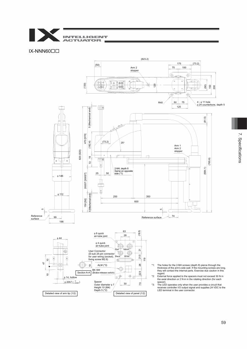
59
7. Specifi cations
IX-NNN60
Arm 2 stopper
4 - 11 hole 24 counterbore, depth 5
5 (M
echa
nica
l end
)
Arm 1 Arm 2 stopper
2-M4, depth 8Same on opposite side (*1)
Reference surface
5 (M
echa
nica
l end
)
6 quick air-tube joint
4 quick air-tube joint
Detailed view of panel (1/2)Detailed view of arm tip (1/2)
14, hollow
Section A-A
*1: The holes for the 2-M4 screws (depth 8) pierce through the thickness of the arm’s side wall. If the mounting screws are long, they will contact the internal parts. Exercise due caution in this regard.
*2: External force applied to the spacers must not exceed 30 N in the axial direction or 2 N m in the rotating direction (for each spacer).
*3: The LED operates only when the user provides a circuit that receives controller I/O output signal and supplies 24 VDC to the LED terminal in the user connector.
Reference surface
Red Yellow
Black White
(823.2)
(50) 175 (73.2)
75 100
(130
)
120
(90)
150
200
50 75
125
R40
146
112
5
99
198
820
(920
)
470
[570
] 20
0ST
[300
ST
] 15
0 [5
0]
7219
(1
82.4
) (73.2)
25 50
25
250 350
600
5
74
(81.
5)
(684
.1)
(765
.6)
63
28
30
(18.
5)
7.5
22.5
28
21
.5
21
119
44
A A
47
10
10
20h7 ( ) 0 - 0.021
19
User Connector (D-sub 25-pin connector for user wiring (socket), fixing screw M2.6)
ALM (*3)
BK SW (Brake-release switch)
Spacer Outer diameter 7 Height 10 (M4) Depth 5 (*2)
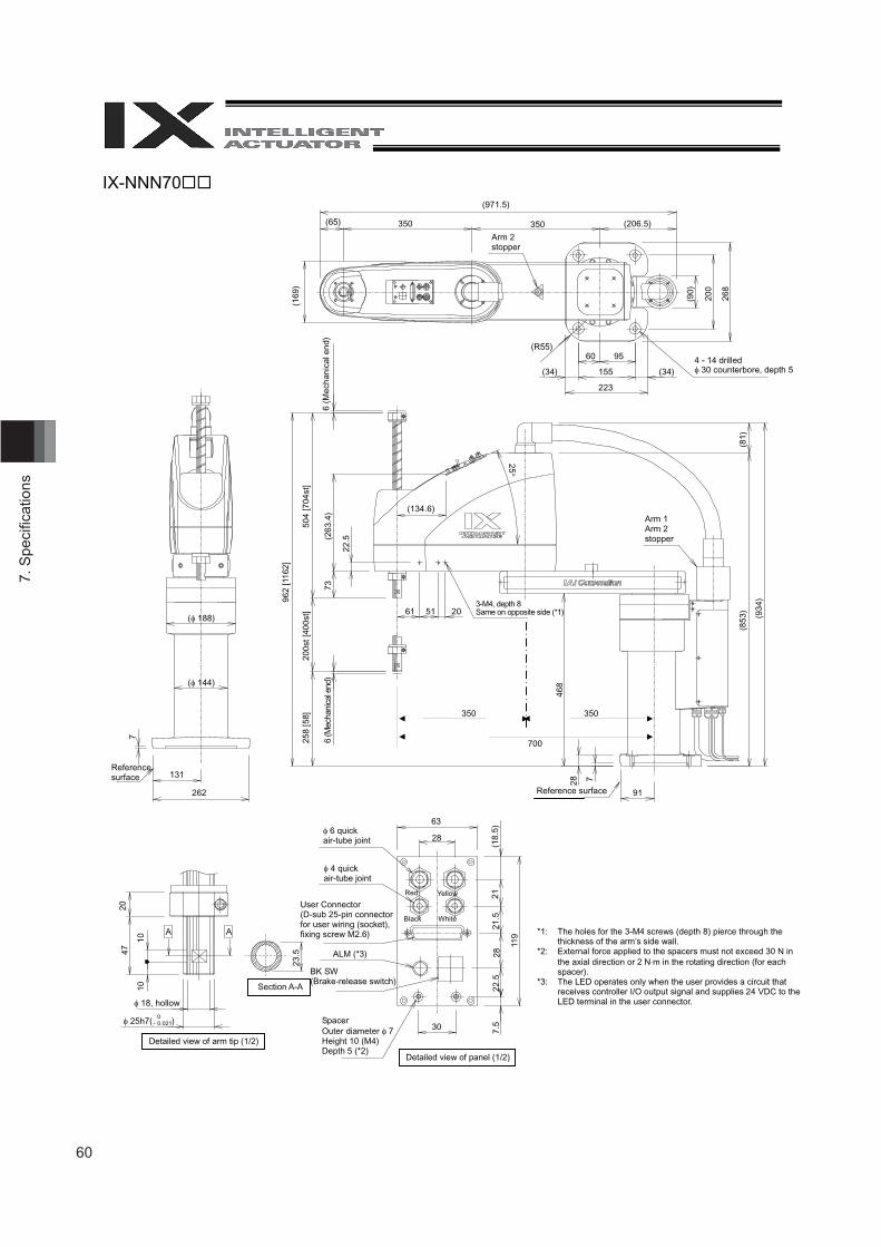
60
7. S
peci
fi cat
ions
IX-NNN70
Arm 2 stopper
4 - 14 drilled 30 counterbore, depth 5
6 (M
echa
nica
l end
)
Arm 1 Arm 2 stopper
3-M4, depth 8Same on opposite side (*1)
Reference surface
6 (M
echa
nica
l end
)
6 quick air-tube joint
4 quick air-tube joint
Detailed view of panel (1/2)
Detailed view of arm tip (1/2)
18, hollow
Section A-A
*1: The holes for the 3-M4 screws (depth 8) pierce through the thickness of the arm’s side wall.
*2: External force applied to the spacers must not exceed 30 N in the axial direction or 2 N m in the rotating direction (for each spacer).
*3: The LED operates only when the user provides a circuit that receives controller I/O output signal and supplies 24 VDC to the LED terminal in the user connector.
7
Reference surface
(971.5)
(65) 350 350 (206.5)
(169
)
(90)
200
268
(R55)60 95
(34) 155 (34)
223
( 188)
( 144)
131
262
962
[116
2]
504
[704
st]
258
[58]
20
0st [
400s
t]
73
(263
.4)
22.5
(134.6)
25
61 51 20
468
(853
) (8
1)
(934
)
91
28
7
20
47 10
10
25h7( )
A A
0 - 0.021
23.5
63
28
30
(18.
5)
7.5
22.5
28
21
.5
21
119
Red Yellow
Black White
User Connector (D-sub 25-pin connector for user wiring (socket), fixing screw M2.6)
ALM (*3)
BK SW (Brake-release switch)
Spacer Outer diameter 7Height 10 (M4) Depth 5 (*2)
350 350
700
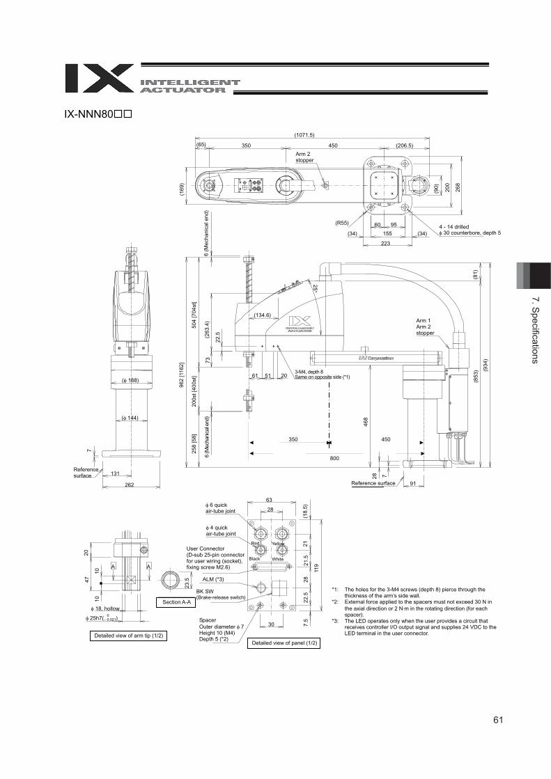
61
7. Specifi cations
IX-NNN80
Arm 2 stopper
4 - 14 drilled 30 counterbore, depth 5
6 (M
echa
nica
l end
)
Arm 1 Arm 2 stopper
3-M4, depth 8Same on opposite side (*1)
Reference surface
6 (M
echa
nica
l end
)
6 quick air-tube joint
4 quick air-tube joint
Detailed view of panel (1/2)Detailed view of arm tip (1/2)
18, hollowSection A-A
*1: The holes for the 3-M4 screws (depth 8) pierce through the thickness of the arm’s side wall.
*2: External force applied to the spacers must not exceed 30 N in the axial direction or 2 N m in the rotating direction (for each spacer).
*3: The LED operates only when the user provides a circuit that receives controller I/O output signal and supplies 24 VDC to the LED terminal in the user connector.
7
Reference surface
(1071.5)
(65) 350 450 (206.5)
(169
)
(90)
200
268
(R55) 60 95
(34) 155 (34)
223
( 188)
( 144)
131
262
962
[116
2]
504
[704
st]
258
[58]
20
0st [
400s
t]
73
(263
.4)
22.5
(134.6)
25
61 51 20
468
(853
) (8
1)
(934
) 91
28
7
20
47 10
10
25h7( )
A A
0 - 0.021
23.5
63
28
30
(18.
5)
7.5
22.5
28
21
.5
21
119
Red Yellow
Black White
User Connector (D-sub 25-pin connector for user wiring (socket), fixing screw M2.6)
ALM (*3)
BK SW (Brake-release switch)
Spacer Outer diameter 7Height 10 (M4) Depth 5 (*2)
350 450
800
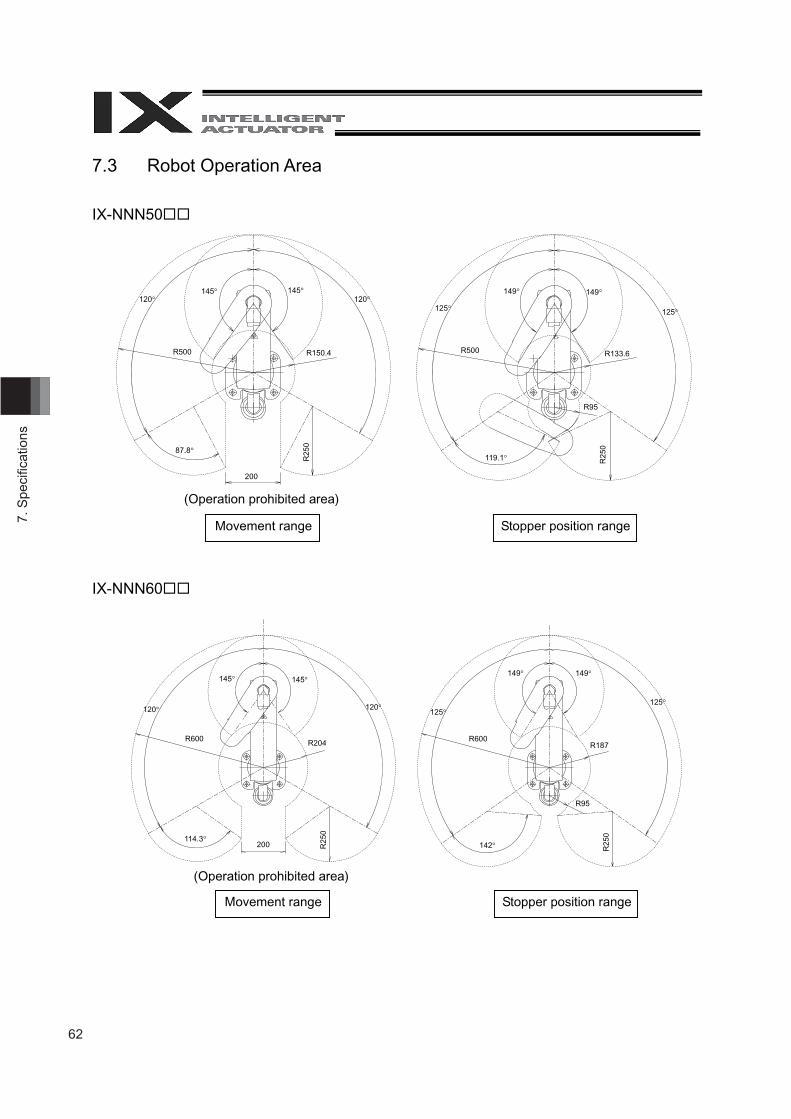
62
7. S
peci
fi cat
ions
7.3 Robot Operation Area
IX-NNN50
IX-NNN60
(Operation prohibited area)
(Operation prohibited area)
Stopper position range Movement range
Stopper position range Movement range
120120145145
R500 R150.4
87.8
200
R25
0 125125
149149
R500 R133.6
119.1 R25
0
R95
120120
145145
R600 R204
114.3
R25
0
125125
149149
R600 R187
142 R25
0
R95
200
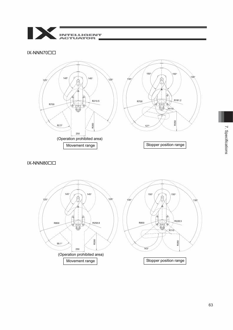
63
7. Specifi cations
IX-NNN70
IX-NNN80
(Operation prohibited area)
Stopper position range Movement range
(Operation prohibited area)
Movement range Stopper position range
125125145145
R700 R210.5
82.5
250
R35
0
130130
150150
R700 R181.2
127 R35
0
R110
125125
145145
R800 R258.8
99.1 R35
0
130130
150150
R800 R228.5
143
R35
0
R110
250
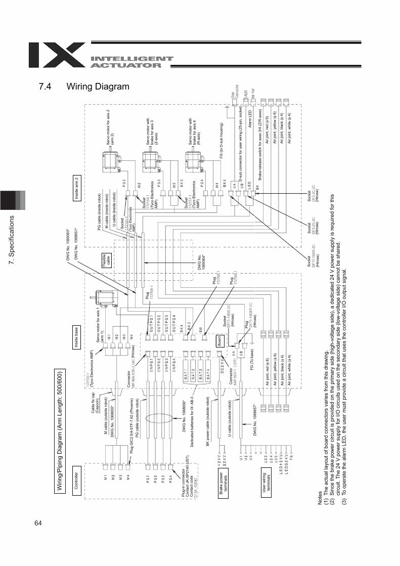
64
7. S
peci
fi cat
ions
Wiri
ng/P
ipin
g D
iagr
am (A
rm L
engt
h: 5
00/6
00)
Con
trolle
r
Cab
le fi
x ca
p (C
apco
n)
M c
able
(out
side
robo
t)
PG c
able
(out
side
robo
t)
BK p
ower
cab
le (o
utsi
de ro
bot)
U c
able
(out
side
robo
t)
Bra
ke p
ower
te
rmin
als
Use
r wiri
ng
term
inal
s
Insi
de b
ase
Serv
o m
otor
for a
xis
1 (a
rm 1
)
Boar
d
FG (T
o ba
se)
Air
join
t, re
d (
6)
Air
join
t, ye
llow
( 6
)
Air
join
t, bl
ack
( 4
)
Air
join
t, w
hite
( 4
)
Flex
ible
ca
ble
Insi
de a
rm 2
PG
cab
le (i
nsid
e ro
bot)
M c
able
(ins
ide
robo
t)
U c
able
(ins
ide
robo
t)
Serv
o m
otor
for a
xis
2 (a
rm 2
)
Serv
o m
otor
with
br
ake
for a
xis
3 (Z
-axi
s)
Serv
o m
otor
with
br
ake
for a
xis
4 (R
-axi
s)
FG (t
o D
-sub
hou
sing
)
D-s
ub c
onne
ctor
for u
ser w
iring
(25-
pin,
soc
ket)
Ala
rm L
ED
Bra
ke-r
elea
se s
witc
h fo
r axe
s 3/
4 (Z
/R-a
xes)
Air j
oint
, red
( 6
)
Air j
oint
, yel
low
( 6
)
Air j
oint
, bla
ck (
4)
Air j
oint
, whi
te (
4)
Ded
icat
ed b
atte
ries
for I
X: A
B-3
DW
G N
o. 1
0686
55*
Plug
GIC
2.5/
4-S
TF-7
.62
(Pho
enix
)
Con
nect
or
Sock
et
(Hiro
se)
(Hiro
se)
Plug
Plu
g
Plu
g
Plug
Sock
et
Sock
et
Sock
et
(Hiro
se)
(Hiro
se)
(Hiro
se)
Plu
g-in
con
nect
or
Con
tact
JK-
SP2
140
(JST
) C
onta
ct c
ode
DW
G N
o. 1
0693
63*
DW
G N
o. 1
0686
51*
(Tyc
o El
ectro
nics
AM
P)
Con
nect
or
DW
G N
o. 1
0686
56*
DW
G N
o. 1
0686
57*
(Hiro
se)
(Tyc
o E
lect
roni
cs
AM
P)
(Tyc
o E
lect
roni
cs
AM
P)
(Tyc
o El
ectro
nics
AM
P)
Sock
et
Sock
et
Soc
ket
DW
G N
o.
1069
364*
Not
es
(1)
The
actu
al la
yout
of b
oard
con
nect
ors
varie
s fro
m th
is d
raw
ing.
(2
) Si
nce
the
brak
e po
wer
circ
uit i
s pr
ovid
ed o
n th
e pr
imar
y si
de (h
igh-
volta
ge s
ide)
, a d
edic
ated
24
V p
ower
sup
ply
is re
quire
d fo
r thi
s ci
rcui
t. Th
e 24
V p
ower
sup
ply
for I
/O c
ircui
ts u
sed
on th
e se
cond
ary
side
(low
-vol
tage
sid
e) c
anno
t be
shar
ed.
(3)
To o
pera
te th
e al
arm
LED
, the
use
r mus
t pro
vide
a c
ircui
t tha
t use
s th
e co
ntro
ller I
/O o
utpu
t sig
nal.
7.4 Wiring Diagram
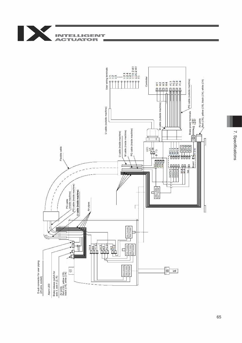
65
7. Specifi cations
D-s
ub c
onne
ctor
for u
ser p
ipin
g (2
5 pi
ns, s
ocke
t)
Ala
rm L
ED
Bra
ke re
leas
e sw
itch
for
axis
3, a
xis
4 (Z
, R)
Air
join
tsR
ed (
6), y
ello
w (
6),
blac
k (
4), w
hite
(4)
P
G c
able
(in
side
mac
hine
) P
G c
able
(ins
ide
mac
hine
)
U c
able
(ins
ide
mac
hine
)
Air
pipe
s
Flex
ible
cab
le
U c
able
(out
side
mac
hine
)
U c
able
(ins
ide
mac
hine
)
U c
able
(ins
ide
mac
hine
)
M c
able
(ins
ide
mac
hine
)
PG
cab
le (i
nsid
e m
achi
ne)
Use
r wiri
ng te
rmin
als
Con
trolle
r
M c
able
(out
side
mac
hine
)
Bra
ke p
ower
term
inal
s P
G c
able
(out
side
mac
hine
)
Air
join
ts
Red
(6)
, yel
low
(6)
, bla
ck (
4), w
hite
(4)
Boa
rd
Axis
4 e
ncod
er
Axi
s 4
mot
or
Axi
s 4
brak
e A
xis
3 br
ake
Axi
s 3
mot
or
Axis
3 e
ncod
er
Axis
2 e
ncod
er
Axi
s 2
mot
or
Axi
s 1
mot
or
Axis
1 e
ncod
er
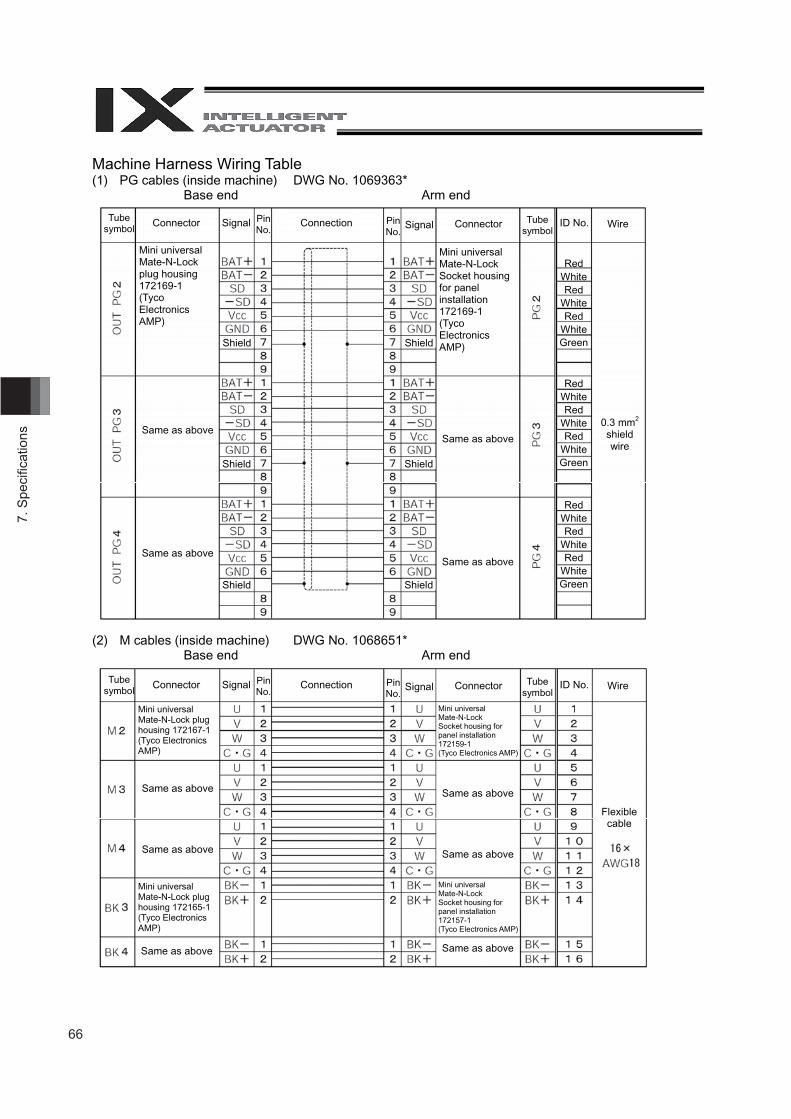
66
7. S
peci
fi cat
ions
Machine Harness Wiring Table (1) PG cables (inside machine) DWG No. 1069363*
Base end Arm end
(2) M cables (inside machine) DWG No. 1068651* Base end Arm end
Shield Shield
Shield Shield
Tube symbol
Connector Signal PinNo.
Connection PinNo.
Signal Connector Tube symbol
ID No. Wire
Mini universal Mate-N-Lock plug housing 172169-1 (Tyco Electronics AMP)
Same as above
Same as above
Mini universal Mate-N-Lock Socket housing for panel installation 172169-1(Tyco ElectronicsAMP)
Same as above
Same as above
RedWhite Red
White Red
White Green
RedWhite Red
White Red
White Green
RedWhite Red
White Red
White Green
0.3 mm2
shieldwire
Shield Shield
Flexible cable
Tube symbol
Connector Signal PinNo.
Connection PinNo.
Signal Connector Tube symbol
ID No. Wire
Mini universal Mate-N-Lock plug housing 172167-1 (Tyco Electronics AMP)
Same as above
Same as above
Mini universal Mate-N-Lock plug housing 172165-1 (Tyco Electronics AMP)
Same as above
Mini universal Mate-N-Lock Socket housing for panel installation 172159-1 (Tyco Electronics AMP)
Same as above
Same as above
Same as above
Mini universal Mate-N-Lock Socket housing for panel installation 172157-1 (Tyco Electronics AMP)
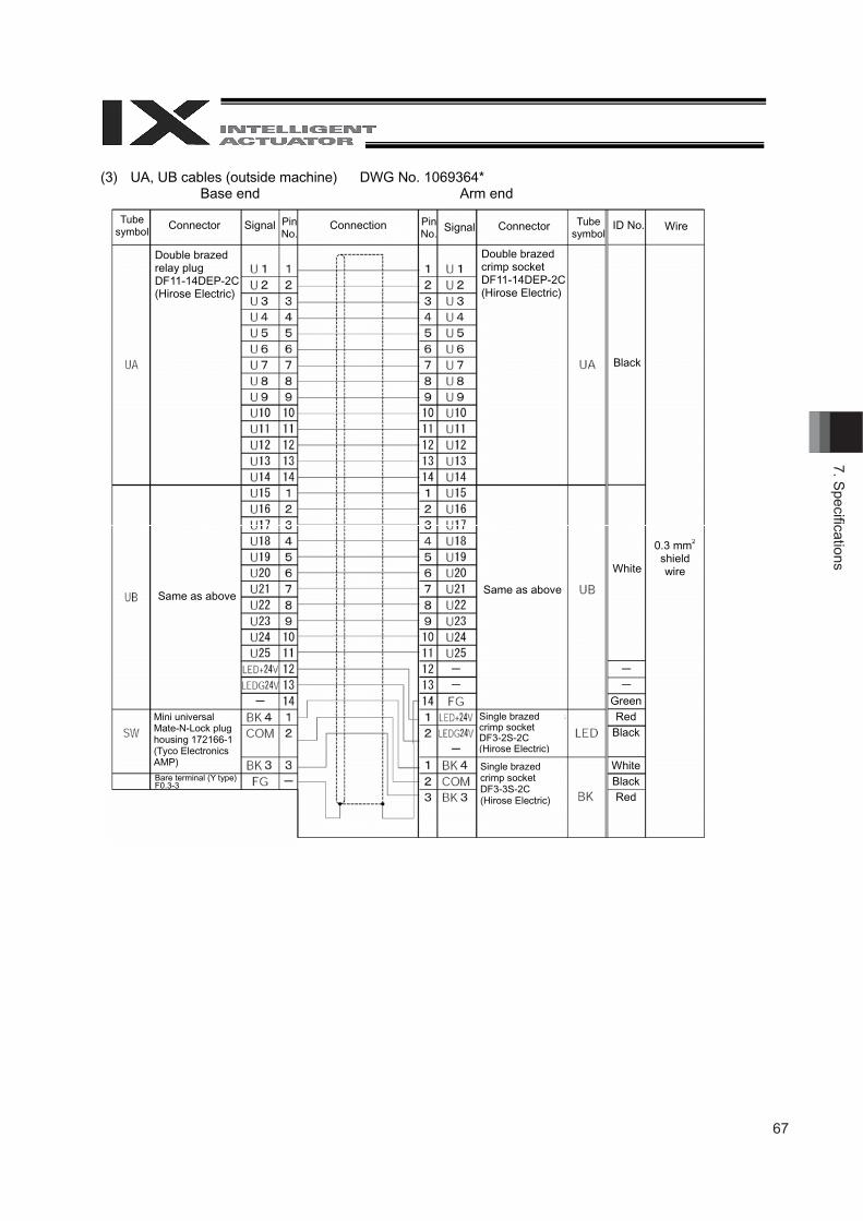
67
7. Specifi cations
(3) UA, UB cables (outside machine) DWG No. 1069364* Base end Arm end
Tube symbol
Connector Signal Connection Signal Connector Tube symbol
ID No. Wire
Double brazed relay plug DF11-14DEP-2C (Hirose Electric)
Same as above Same as above
Mini universal Mate-N-Lock plug housing 172166-1 (Tyco Electronics AMP)
Bare terminal (Y type) F0.3-3
Double brazed crimp socket DF11-14DEP-2C(Hirose Electric)
0.3 mm2
shield wire
Black
White
GreenRed
Black
White BlackRed
Single brazed crimp socket DF3-2S-2C(Hirose Electric)
Single brazed crimp socket DF3-3S-2C(Hirose Electric)
Pin No.
PinNo.
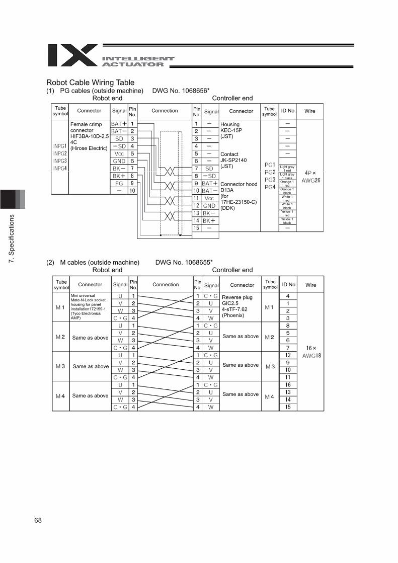
68
7. S
peci
fi cat
ions
Robot Cable Wiring Table (1) PG cables (outside machine) DWG No. 1068656*
Robot end Controller end
(2) M cables (outside machine) DWG No. 1068655* Robot end Controller end
Tube symbol
Connector Signal Connection Signal Connector Tube symbol
ID No. Wire
Female crimp connector HIF3BA-10D-2.54C (Hirose Electric)
HousingKEC-15P (JST)
Contact JK-SP2140 (JST)
Connector hood D13A (for 17HE-23150-C) (DDK)
Light gray 1 red
Light gray 1 black
Orange 1 red
Orange 1 black
White 1 red
White 1 black
Yellow 1 red
Yellow 1 black
Tube symbol
Connector Signal Connection Signal ConnectorTube
symbol ID No. Wire
Mini universal Mate-N-Lock socket housing for panel installation172159-1 (Tyco Electronics AMP)
Same as above
Same as above
Same as above
Reverse plug GIC2.54-sTF-7.62 (Phoenix)
PinNo.
Pin No.
PinNo.
PinNo.
Same as above
Same as above
Same as above
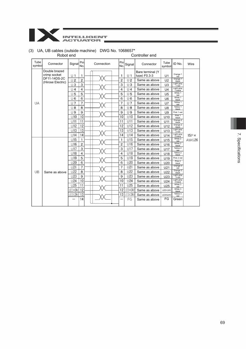
69
7. Specifi cations
(3) UA, UB cables (outside machine) DWG No. 1068657* Robot end Controller end
Tube symbol
Connector Signal Connection Signal Connector Tube symbol
ID No. WirePinNo.
PinNo.
Double brazed crimp socket DF11-14DS-2C (Hirose Electric)
Same as above
Bare terminal (Y type) F0.3-3Same as aboveSame as aboveSame as aboveSame as aboveSame as aboveSame as aboveSame as aboveSame as aboveSame as aboveSame as aboveSame as aboveSame as aboveSame as aboveSame as aboveSame as aboveSame as aboveSame as aboveSame as aboveSame as aboveSame as aboveSame as aboveSame as aboveSame as aboveSame as aboveSame as aboveSame as aboveSame as above
U1U2U3U4U5U6U7U8U9
U10U11 U12U13U14U15U16U17U18U19U20U21U22U23U24U25
LED+24V
LEDG24V
FG
Orange 1 red
Orange 1 black
Light gray 1 red
Light gray 1 black White 1
redWhite 1 black
Yellow 1 red
Yellow 1 black
Pink 1 red
Pink 1 black
Orange 2 black
Orange 2 black
Light gray 2 red
Light gray 2 black White 2
redWhite 2 black
Yellow 2 red
Yellow 2 black
Pink 2 red
Pink 2 black
Orange 3 red
Orange 3 black
Light gray 3 red
Light gray 3 black White 3
redWhite 3 black
Yellow 3 red
Green
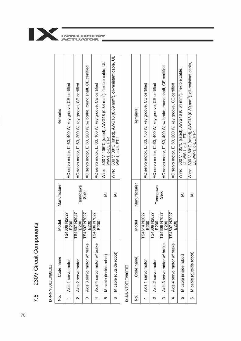
70
7. S
peci
fi cat
ions
7.5
230V
Circ
uit C
ompo
nent
s
IX-N
NN
50/6
0
No.
C
ode
nam
e M
odel
M
anuf
actu
rer
Rem
arks
1 Ax
is 1
ser
vo m
otor
TS
4609
N20
27
E200
AC
ser
vo m
otor
, 6
0, 4
00 W
, key
gro
ove,
CE
certi
fied
2 Ax
is 2
ser
vo m
otor
TS
4607
N20
27
E200
AC
ser
vo m
otor
, 6
0, 2
00 W
, key
gro
ove,
CE
certi
fied
3 A
xis
3 se
rvo
mot
or w
/ bra
ke
TS46
07 N
7027
E2
00
AC s
ervo
mot
or,
60,
200
W, w
/ bra
ke, r
ound
sha
ft, C
E c
ertif
ied
4 A
xis
4 se
rvo
mot
or w
/ bra
ke
TS46
06 N
7027
E2
00
Tam
agaw
a S
eiki
AC s
ervo
mot
or,
60,
100
W, k
ey g
roov
e, C
E ce
rtifie
d
5 M
cab
le (i
nsid
e ro
bot)
IAI
Wire
: 30
0 V,
105
C (r
ated
), AW
G18
(0.8
4 m
m2 ),
flexi
ble
cabl
e, U
L V
W-1
, c-U
L FT
-1
6 M
cab
le (o
utsi
de ro
bot)
IAI
Wire
: 30
0 V,
80
C (r
ated
), AW
G18
(0.8
9 m
m2 ),
oil-r
esis
tant
cab
le, U
L V
W-1
, c-U
L FT
-1
IX-N
NN
70/8
0
No.
C
ode
nam
e M
odel
M
anuf
actu
rer
Rem
arks
1 Ax
is 1
ser
vo m
otor
TS
4614
N20
27
E200
AC
ser
vo m
otor
, 8
0, 7
50 W
, key
gro
ove,
CE
certi
fied
2 Ax
is 2
ser
vo m
otor
TS
4609
N20
27
E200
AC
ser
vo m
otor
, 6
0, 4
00 W
, key
gro
ove,
CE
certi
fied
3 A
xis
3 se
rvo
mot
or w
/ bra
ke
TS46
09 N
7027
E2
00
AC s
ervo
mot
or,
60,
400
W, w
/ bra
ke, r
ound
sha
ft, C
E c
ertif
ied
4 A
xis
4 se
rvo
mot
or w
/ bra
ke
TS46
07 N
2027
E2
00
Tam
agaw
a S
eiki
AC s
ervo
mot
or,
60,
200
W, k
ey g
roov
e, C
E ce
rtifie
d
5 M
cab
le (i
nsid
e ro
bot)
IAI
Wire
: 30
0 V,
105
C (r
ated
), AW
G18
(0.8
4 m
m2 ),
flexi
ble
cabl
e,
UL
VW-1
, c-U
L FT
-1
6 M
cab
le (o
utsi
de ro
bot)
IAI
Wire
: 30
0 V,
80
C (r
ated
), AW
G18
(0.8
9 m
m2 ),
oil-r
esis
tant
cab
le,
U
L VW
-1, c
-UL
FT-1
58
71
8. Warranty
8. Warranty
8.1 Warranty Period One of the following periods, whichever is shorter: 18 months after shipment from our company 12 months after delivery to the specified location 2,500 hours of operation
8.2 Scope of Warranty Our products are covered by warranty when all of the following conditions are met. Faulty products covered by warranty will be replaced or repaired free of charge:
(1) The breakdown or problem in question pertains to our product as delivered by us or our authorized dealer.
(2) The breakdown or problem in question occurred during the warranty period.
(3) The breakdown or problem in question occurred while the product was in use for an appropriate purpose under the conditions and environment of use specified in the operation manual and catalog.
(4) The breakdown of problem in question was caused by a specification defect or problem, or by a quality issue with our product.
Note that breakdowns due to any of the following reasons are excluded from the scope of warranty: [1] Anything other than our product [2] Modification or repair performed by a party other than us (unless we have approved such
modification or repair) [3] Anything that could not be easily predicted with the level of science and technology available
at the time of shipment from our company [4] A natural disaster, man-made disaster, incident or accident for which we are not liable [5] Natural fading of paint or other symptoms of aging [6] Wear, depletion or other expected result of use [7] Operation noise, vibration or other subjective sensation not affecting function or maintenance
Note that the warranty only covers our product as delivered and that any secondary loss arising from a breakdown of our product is excluded from the scope of warranty.
8.3 Honoring the Warranty As a rule, the product must be brought to us for repair under warranty.
8.4 Limited Liability (1) We shall assume no liability for any special damage, consequential loss or passive loss such as a
loss of expected profit arising from or in connection with our product. (2) We shall not be liable for any program or control method created by the customer to operate our
product or for the result of such program or control method.

72
8. W
arra
nty
8.5 Conditions of Conformance with Applicable Standards/Regulations, Etc., and Applications
(1) If our product is combined with another product or any system, device, etc., used by the customer, the customer must first check the applicable standards, regulations and/or rules. The customer is also responsible for confirming that such combination with our product conforms to the applicable standards, etc. In such a case we will not be liable for the conformance of our product with the applicable standards, etc.
(2) Our product is for general industrial use. It is not intended or designed for the applications specified below, which require a high level of safety. Accordingly, as a rule our product cannot be used in these applications. Contact us if you must use our product for any of these applications:
[1] Medical equipment pertaining to maintenance or management of human life or health [2] A mechanism or mechanical equipment intended to move or transport people (such as a
vehicle, railway facility or aviation facility) [3] Important safety parts of mechanical equipment (such as safety devices) [4] Equipment used to handle cultural assets, art or other irreplaceable items
(3) Contact us at the earliest opportunity if our product is to be used in any condition or environment that differs from what is specified in the catalog or operation manual.
8.6 Other Items Excluded from WarrantyThe price of the product delivered to you does not include expenses associated with programming, the dispatch of engineers, etc. Accordingly, a separate fee will be charged in the following cases even during the warranty period:
[1] Guidance for installation/adjustment and witnessing of test operation [2] Maintenance and inspection [3] Technical guidance and education on operating/wiring methods, etc. [4] Technical guidance and education on programming and other items related to programs
73
Change H
istory
Change History
Revision Date Revision Description
April 2011
March 2012
August 2012
Fourth Edition
Fifth edition
Sixth edition
A page for CE Marking added
Introduction, Safety Symbols and Safety Precautions are deletedPg. 1 to 7Pg. 8Pg. 18
Pg. 28
Pg. 50, 52, 54, 56
Pg. 70, 71
4.1 Installation Posture added
Safety Guide addedCaution in Handling addedBrake voltage source capacity from 20W to 30W changed to 20WCaution notes added telling to go to see the doctor to have an appropriate treatment when the grease got into an eye
Brake voltage source capacity 20W added to specificationsContents changed in 8. Warranty


Manual No.: ME3620-6B (October 2014)
The information contained in this document is subject to change without notice for purposes ofproduct improvement.Copyright © 2014. Oct. IAI Corporation. All rights reserved.
14.10.000
Head Office: 577-1 Obane Shimizu-KU Shizuoka City Shizuoka 424-0103, JapanTEL +81-54-364-5105 FAX +81-54-364-2589
website: www.iai-robot.co.jp/
Ober der Röth 4, D-65824 Schwalbach am Taunus, GermanyTEL 06196-88950 FAX 06196-889524
SHANGHAI JIAHUA BUSINESS CENTER A8-303, 808, Hongqiao Rd. Shanghai 200030, ChinaTEL 021-6448-4753 FAX 021-6448-3992
website: www.iai-robot.com
Technical Support available in USA, Europe and China
Head Office: 2690 W. 237th Street, Torrance, CA 90505TEL (310) 891-6015 FAX (310) 891-0815
Chicago Office: 110 East State Parkway, Schaumburg, IL 60173TEL (847) 908-1400 FAX (847) 908-1399
TEL (678) 354-9470 FAX (678) 354-9471website: www.intelligentactuator.com
Atlanta Office: 1220 Kennestone Circle, Suite 108, Marietta, GA 30066


![Fellowship : Alphabetic...69/1, SK Deb Road, Kolkata 700 048 [Tel : (033) 2534 7643 (R); M-9831296680] BASU, Joyoti (IX) joyotibasu@gmail.com 1A, Madhab Chatterjee Street, Kolkta 700](https://img.pdfslide.us/doc/110x75/60b691a1d5dd0639157e6531/fellowship-alphabetic-691-sk-deb-road-kolkata-700-048-tel-033-2534.jpg)