Embed Size (px)
Citation preview

Central Washington University Central Washington University
ScholarWorks@CWU ScholarWorks@CWU
All Undergraduate Projects Undergraduate Student Projects
Spring 2016
Tabletop Die Cast System Tabletop Die Cast System
Brad C. Barringer Central Washington University, [email protected]
Follow this and additional works at: https://digitalcommons.cwu.edu/undergradproj
Part of the Other Mechanical Engineering Commons
Recommended Citation Recommended Citation Barringer, Brad C., "Tabletop Die Cast System" (2016). All Undergraduate Projects. 14. https://digitalcommons.cwu.edu/undergradproj/14
This Dissertation/Thesis is brought to you for free and open access by the Undergraduate Student Projects at ScholarWorks@CWU. It has been accepted for inclusion in All Undergraduate Projects by an authorized administrator of ScholarWorks@CWU. For more information, please contact [email protected].
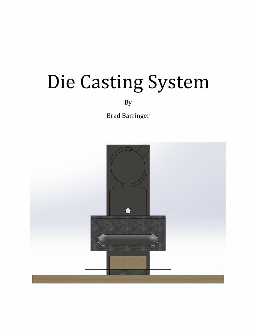
Die Casting System
By
Brad Barringer

Table of Contents 1. INTRODUCTION ......................................................................................................................................... 1
A. Motivation ............................................................................................................................................ 1
B. Function Statement .............................................................................................................................. 1
C. Requirements ........................................................................................................................................ 1
D. Engineering Merit ................................................................................................................................. 1
E. Scope of Effort ....................................................................................................................................... 2
F. Success Criteria ..................................................................................................................................... 2
2. DESIGN & ANALYSIS .................................................................................................................................. 2
A. Approach: Proposed Solution ............................................................................................................... 2
B. Description ............................................................................................................................................ 2
C. Benchmark ............................................................................................................................................ 2
D. Performance Predictions ...................................................................................................................... 3
E. Description of Analyses ......................................................................................................................... 3
F. Scope of Testing and Evaluation ........................................................................................................... 3
G. Analysis ................................................................................................................................................. 3
i. Approach: Proposed Sequence .......................................................................................................... 5
ii. Calculated Parameters ...................................................................................................................... 5
3. METHODS & CONSTRUCTION ................................................................................................................... 6
A. Construction ......................................................................................................................................... 6
i. Description ......................................................................................................................................... 6
ii. Drawing Tree ..................................................................................................................................... 7
iii. Parts List and Labels ......................................................................................................................... 7
iv. Manufacturing Issues ....................................................................................................................... 8
v. Discussion of assembly, sub-assemblies, parts, and drawings ......................................................... 8
4. TESTING METHOD ..................................................................................................................................... 8
A. Introduction .......................................................................................................................................... 8
B. Method/Approach ................................................................................................................................ 8
C. Test Procedure ...................................................................................................................................... 8
i. Designer Test ...................................................................................................................................... 9
ii. Instructor Test ................................................................................................................................... 9
D. Deliverables .......................................................................................................................................... 9
5. BUDGET/SCHEDULE/PROJECT MANAGEMENT ......................................................................................... 9
A. Proposed Budget .................................................................................................................................. 9
B. Proposed Schedule ............................................................................................................................. 10

C. Project Management .......................................................................................................................... 10
i. Human Resources ............................................................................................................................ 10
ii. Physical Resources .......................................................................................................................... 11
iii. Soft Resources ................................................................................................................................ 11
D. Actual Budget ..................................................................................................................................... 11
E. Actual Schedule ................................................................................................................................... 11
6. DISCUSSION ............................................................................................................................................. 11
7. CONCLUSION ........................................................................................................................................... 13
8. ACKNOWLEDGEMENTS ........................................................................................................................... 13
9. REFERENCES ............................................................................................................................................ 13
10. APPENDIX A – Analyses ......................................................................................................................... 14
11. APPENDIX B – Drawings ........................................................................................................................ 25
A. Models ................................................................................................................................................ 25
i. Rough Model 1 ................................................................................................................................. 25
ii. Rough Model 2 ................................................................................................................................ 26
iii. Rough Model 3 ............................................................................................................................... 27
iv. Rough Model 4 ............................................................................................................................... 28
v. Rough Model 5 ................................................................................................................................ 29
vi. Final Model ..................................................................................................................................... 30
vii. Final Model Revision 1................................................................................................................... 31
B. Drawings ............................................................................................................................................. 32
i. Rough Model 3 Drawings ................................................................................................................. 32
ii. Final Model Drawings ...................................................................................................................... 38
iii. Assembly Drawings ........................................................................................................................ 45
iv. Build Revision Drawings ................................................................................................................. 48
12. APPENDIX C – Parts List ......................................................................................................................... 55
13. APPENDIX D – Budget ........................................................................................................................... 55
14. APPENDIX E – Schedule ......................................................................................................................... 56
A. Fall 2015 Schedule .............................................................................................................................. 56
B. Winter and Spring 2016 Schedule ...................................................................................................... 57
15. APPENDIX F – Testing Report ................................................................................................................ 58
Introduction: ........................................................................................................................................... 58
Method/Approach: ................................................................................................................................. 58
Test Procedure: ....................................................................................................................................... 58
Must weigh no more than 20lb........................................................................................................... 58

Must fit into a space no larger than 20in x 25in x 8in......................................................................... 58
Pour test / must work with Aluminum. .............................................................................................. 59
Deliverables: ........................................................................................................................................... 59
Appendix: ................................................................................................................................................ 60
16. Appendix G – Resume ........................................................................................................................... 61

1
1. INTRODUCTION A. Motivation This projected is motivated by the need to expand the educational equipment available to the instructor when teaching MET 257 – Casting Processes in the foundry. Some of the design choices for this project were motivated by the designer’s desire to expand their knowledge of ceramics and casting in general. There are two factors that influenced the size of the system. The first is the need for the system to fit into the limited space available in the foundry. A larger, or permanently located, system would be an unnecessary burden on the foundry and those who would have to navigate around the system. The second is to allow for proper attention to every aspect of the system within the limited time windows for design and fabrication. A larger system would be more intricate and with the limited time scale of the project there would be a risk of not having time to properly analyze or design part of the system. The general shape and design of the project is based on a description of the type of system the MET 257 instructor would like to have for teaching die casting to student’s in MET 257. The initial description is to have a self-tilting system that will tilt the mold with the pouring device to accommodate a smoother pour into the mold. Based on this initial description design decisions will be made to incorporate the desired features while optimizing the system for size, weight, and cost.
B. Function Statement The system must demonstrate the die casting process to students in MET 257 – Casting Processes.
C. Requirements The requirements for this project are:
Must demonstrate the die casting process.
Must be compatible with the currently available casting equipment and space.
Must weigh no more than 20lb.
Must fit into a space no larger than 20in x 25in x 8in.
Must work with Aluminum.
Must be designed to tilt.
Must be able to be operated by the MET 257 instructor without assistance. As per Customer.
Must cost less than $200 in parts that aren’t donated.
D. Engineering Merit The design of this project has required thorough knowledge of casting and more specifically the die casting process. Extensive research has been required to acquire this knowledge of casting as well as assistance from Joe Coupe and Dr. Johnson in understanding the die casting process. Analyzing the system will require equations and methods from statics and strength of materials to check that all the dimensions will be sufficient to support the system in both its resting position and its standing position. Analyzing the heat capabilities of the system will require knowledge of heat transfer and dissipation.

2
E. Scope of Effort The scope of this project will be to design and manufacture a die cast system to be used in the foundry to teach students about die casting. The scope of the design phase is to design a tabletop die casting system and analyze the system to ensure proper performance. The scope of the manufacturing phase of this project will be to manufacture and assemble all of the part of the system. The die for testing the system will be all be manufactured as a side project. The scope of the testing phase of the project will be to test the system to ensure it does create a work piece of acceptable dimensions and that the system can be operated without instruction or guidance from the designer.
F. Success Criteria This project will be deemed a success if the system can be used by the instructor of MET 257 to demonstrate die casting without assistance from the system’s designer.
2. DESIGN & ANALYSIS A. Approach: Proposed Solution Design and manufacture a simple system that demonstrates die casting. A usable work piece is defined as a work piece that is in the desired shape and can be worked into a finished product with less than two hours of finishing processes. The life span of a material will be an estimate of the time frame a part of the system fabricated from the material will function until it needs to be replaced. The core of the design will be the lever arm and the die holding at the end of the lever arm.
B. Description The system will have a solid base and a lever arm that holds the mold and the ladle. The lever arm will be able to tilt 90°, from horizontal to vertical, to allow for a smooth pour into the mold. The die holding will be incorporated into the lever arm and will hold the mold and the ladle. The die holding will be designed to hold the mold and the ladle so that the aluminum in the ladle will pour into the mold as the lever arm is rotated 90° from horizontal to vertical.
C. Benchmark The benchmark for this project isn’t a similarly designed system but a system designed to produce products of a similar size and on a similar scale. The benchmark comparison will be the ability to produce a usable work piece with a small die cast system. The intention is to improve on the benchmark by designing a system that tilts the mold with the ladle to optimize the pouring process. The URL below is for a website that has images and information on this projects benchmark. http://www.custompartnet.com/wu/permanent-mold-casting

3
Based on the image shown of the Permanent Mold System and the dimensions of a common piston head. It can be estimated that the system can produce work pieces that are roughly 4x4x3in in size and the unit can produce a single work piece at a time. The project’s system will produce a smaller work piece but of superior quality due to the improved pour system. The production rate of the project’s system should be higher because smaller work pieces should cool faster.
D. Performance Predictions The project is predicted to successfully demonstrate the die casting process. If MET 257 continues to be taught only once a year, then the project is predicted to operate for five years without maintenance and ten years without needing replacement parts.
E. Description of Analyses The weight analysis of the system will be based off of the estimated weights of each of the parts. The estimated weights will be listed in the calculated parameters and in appendix 10. The estimated weights will be based off of retailer and manufacturer densities and the volumes for each SolidWorks Part. The analysis of this project will be designed around the requirements and ensuring that the requirements are met. This analysis philosophy is designed to ensure that the system is engineered properly but not over engineered. Proper engineering will ensure that the system will perform as desired while not having redundant material or supports that just add weight. For the mathematically based requirements, e.g. weight and dimensions, the analysis will be based on model volumes and manufacturer densities for each material. All dimensions will be designed for ease of manufacture and construction based on commonly available sizes and dimensions. The requirements that aren’t mathematically based will be discussed in G. Analysis. Each requirement will be discussed in depth to ensure that the requirement is being met and that it is for the project’s benefit. Other design features and parts of the system may be analyzed mathematically if they require or justify such analysis.
F. Scope of Testing and Evaluation The project will be tested in two settings. The first setting will be in the casting lab and performed by the engineer that has designed and fabricated the die cast system. This first test will be to determine if the system can produce a die cast part and demonstrate the die casting process. The second setting will be again in the casting lab but the second test will be performed by the MET 257 instructor to determine if the system can be operated by the instructor without assistance or instruction. In both test cases the success of the system will be determined by the system’s ability to produce a usable work piece.
G. Analysis Base Analysis The project is designed to be moved so the base has to be analyzed to assess if the base will break from the bending moment caused by the components on it. See Green Sheets 6 and 7 for the full calculations and analysis of the base. The calculations show that the base should not break under the strain of the system’s components. Green Sheets 8 and 9 show the hand calculations for the deformation of the base

4
that are used to compare to the FEA analysis results in Appendix A. Kinematics The kinematic sequence for the system is visually displayed in Appendix A. The kinematics of the system are the angular rotation of the lever arm from a horizontal position to a vertical position. The visuals in Appendix A have had some of the system components removed to allow for easier viewing of the component that is actually moving. The motion is achieved by applying force to the handle. Must demonstrate the die casting process: This requirement is the core of the entire project. Demonstrating the die casting process is the entire reason for the project. This requirement will be met if the system is produces a metal work piece by pouring molten aluminum into a die. This is the core of the project and what every part of the project is designed around. The system isn’t intended to demonstrate all of the complexities and possibilities of die casting. The system is intended to demonstrate the basic concept and process of die casting. Must be compatible with the currently available casting equipment and space: Part of meeting this requirement is meeting the size requirements. The size requirement will be addresses later in this section and will include commentary on how it meets this requirement as well. The furnaces currently in the foundry are capable of melting aluminum and allow for ladling of molten aluminum. The system is designed to be used with any ladle that will fit in the ladle holding. The ladle holding was designed to hold a ladle of the appropriate size to hold enough molten aluminum to fill the die that will be manufactured to work with the system. Must weigh no more than 20lb:
This requirement will be estimated based on the density provided by retailers and manufacturers and the volume for each part as determined by the model. See Green Sheet 1 for calculations and total estimated weight. Must fit into a space no larger than 20in x 25in x 8in: The purpose of this requirement is to ensure that the system will fit in the allotted space for its storage, as well as ensuring the system is small enough to be carried by a single person. For calculations see Green Sheet 2. Must work with Aluminum: When casting the system used has to be designed to function when subjected to the temperatures that the requirement metal melts at. Research into casting aluminum has found a temperature range of roughly 880°F to 1200°F. The system will be designed to operate with 1200°F molten aluminum. See Green Sheets 4 and 5 for the heat calculations. Must be designed to tilt: One of the core concepts of the system’s design was that the system needed to tilt the die and the ladle at the same time to allow for a smoother pour. The system could have been designed to tilt in various other ways but the size requirement of the size made it difficult to have a system that would tilt and fit in the required space. The lever arm design was the design chosen because it would allow for the necessary tilt while allowing the system to lay mostly flat when at rest so that the system could be stored in the designated space. An alternate design was considered by rejected before any models were made because the design was centered about a spherical profile that would have been too large.

5
Must be able to be operated by the MET 257 instructor without assistance: This requirement comes directly from the client. The MET 257 instructor wants a system that is simple enough that it doesn’t require extensive instructions or assembly of the system. The complexity and design of the system also shouldn’t distract from or deter casting students from understanding the die casting process. Must cost less than $200 in parts that aren’t donated: As a piece of educational equipment that system is being designed not to be a financial burden on the department. It is also intended that any replacement parts that become necessary in later years are not a major financial concern for the department or the MET 257 instructor. The major expense of the project will be the steel flat bar for the die holding which shouldn’t need to be replaced. See table 4 in Appendix D for cost estimates. FEA Analysis: Simulation Mechanical was used to perform an FEA analysis of the system’s base to aid in determining the accuracy of the deformation and forces calculations. There is less than a .1% difference between the hand calculations and the FEA analysis.
i. Approach: Proposed Sequence Approach 1: A flat square base plate with a single lever arm. Approach 2: A circular base plate. Rejected for taking up too much space without adding any engineering benefit. Approach 3: All wood is being replaced with aluminum parts for fire concerns. Approach 4: Wood has returned and die-holding has been slimmed down. Approach 5: Some of the wood was removed for heat reasons and the bottom half of the die-holding and the lever arm became one piece. Approach 6: Redesign of the die holding rest and the die holding to accommodate clamping of the die to ensure proper closing. Approach 7: Add head and hand shield to the design.
ii. Calculated Parameters Part Density (lb/in3) Volume (in3) Weight (lb)
Die Holding Arm .28 39.51 11.20
Base .01228 221.32 2.72
Hinge .29 1.11 .32
Arm Rest .28 3.43 .96
Hinge Support .01228 8.40 .10
Handle .28 8.64 2.45
Heat Shield .28 3.82 1.09
Hand Shield .28 1.50 .43
Hardware 1.00
Total 20.27
TABLE 1: WEIGHT CALCULATIONS
6
3. METHODS & CONSTRUCTION A. Construction i. Description Each material or purchased part will be assigned an alpha-numerical code. A complete list of the parts of the project and their project codes are listed in Appendix C. The project codes will be used to identify parts on the drawings. The rest of the project will rest on the base to allow the project to be moved and stored. The lever arm will support the die holding and be attached to the hinge support and rest on the die holding rest. The die-holding will hold the die and the ladle so that they move together for a smoother pour. SolidWorks will be used to design a 3D model of the die holding and to specify CNC processes. After the CNC processes mill out the die and ladle holding the handle will be bolted to the die holding and the ladle stop will be welded on. The remaining A36 flat bar will be used to manufacture the die holding rest and will be bolted onto the base. The hinge support will be attached to the base with wood screws and the hinge will be attached to the hinge support with wood screws. The last step will be to attach the die holding to the hinge with bolts. The hand shield must be placed on the handle before the handle is attached to the die holding arm. The heat shield must be in place around the hinge support and arm rest before the die holding arm is attached to the hinge support.

7
ii. Drawing Tree
FIGURE 1
iii. Parts List and Labels Part Number Part Name Quantity
W1 Plywood Base 1
W2 Hinge Support 1
H1 Flat Butt Hinge 1
H2 #12 wood screws – 1 in 3
H3 #12 wood screws – 2 in 3
H4 C-Clamp 2
H5 ¼ - 28 Hex bolts – 1 in 5
H6 ¼ - 28 Hex bolts – 2 in 2
M1 Die Holding Arm 1
M2 Die Holding Rest 1
FMA1 Die Cast System
FMSA1 Base Assembly
FM1 Base
FM2 Arm Rest
FM3 Hinge Support
FM6 Heat Shield
H1 Hinge
FMSA2 Lever Arm Assembly
FM4 Die Holding Arm
FM5 Handle
FM7 Hand Shield

8
M3 Handle 1
A1 Casting Ladle 1
S1 Heat Shield 1
S2 Hand Shield 1
TABLE 2
iv. Manufacturing Issues There were only minor manufacturing issues. The CNC Mill work done to the lever arm had to have the pathways redesigned due to the CNC Mill being optimized for high speed shallow cuts instead of low RPM deep cuts. The handle for the system was also redesigned for ease of manufacturing to accommodate non-project related injuries to the designer and manufacturing support.
v. Discussion of assembly, sub-assemblies, parts, and drawings The system contains two major sub-assemblies. The first is the lever arm assembly which consists of the die holding and the handle. These parts are grouped into a sub assembly because they will be attached to each other before being attached to the rest of the parts and they operate together. The second sub-assembly is the base. The base will consist of the base, the die holding rest, the hinge support, and the hinge. Again the driving factor for classifying these parts as a sub-assembly is that they will be assembled together before being attached to the other sub-assembly.
4. TESTING METHOD A. Introduction The testing of this project will occur in two main steps. The first step will be testing if the system successfully produces the desired part. This step of the testing will test just the system and its performance. The second step will be testing the system’s ability to perform as designed in an academic setting. The system will be operated by the instructor of MET 257 to test if the system can be operated without assistance from the system’s designer. This test will evaluate the system’s ability to operate as designed in an academic setting.
B. Method/Approach The first step of testing will consist of the system designer using the system to fabricate a work piece to test the system’s ability to produce a usable work piece. The second step of testing will consist of the instructor of MET 257 using the system to demonstrate die casting by using the system to produce a usable work piece.
C. Test Procedure The procedure for the designer test will be more detailed then the instructor test because the designer test will be designed to test the system’s part and performance while the instructor test will simply test the systems viability as an educational tool.

9
i. Designer Test This test will be designed to test the functionality of the system to ensure that the system meets its requirements and produces work pieces. A checklist of each requirement will be listed below to be used when testing the system to ensure each requirement is met. Checklist:
o Cost less than $200? o Fit into the designated storage space? o Weighs less than 20 lb? o Fit into the foundry and operated in the space available without needing special equipment? o Didn’t suffer any heat related issues? o Tilted the die and the ladle at the same time? o Produced a work piece?
Below are the actions that will be taken for each of the above check list items. To assess if the cost was under the given limit the cost of all of the parts that were purchased will be totaled. If they are under $200 then the system will pass this check. To assess if the system has met the size requirements that system will be placed into the designated storage space. If the system fits in the space then it passes this check. To assess the weight of the system a scale will be placed under the system. If the system is too large for the available equipment then the system will be disassembled and weighed a part at a time. If the total system or the sum of all the parts is less than 20 lb then the system will pass this check. To assess the final four checks on the list the system will be set up and run through a full production cycle of at least one work piece. If the system is able to produce a work piece without suffering any damage in the space available then the final four checks will be passed.
ii. Instructor Test This test will be to ensure that the system meets the success criteria and the customer specified requirement. The procedure for this test will be more fluid as it will be a test of the instructor’s ability to demonstrate die casting to the students and not a quantifiable measurement. If the system produces a usable work piece during the lecture/demonstration without assistance from the designer then it will have passed the requirement and will be deemed a success.
D. Deliverables For the designer’s test the deliverables will be a checklist of each requirement and a usable work piece. For the instructor’s test the only deliverable will be a usable work piece.
5. BUDGET/SCHEDULE/PROJECT MANAGEMENT A. Proposed Budget The parts for the system will cost no more than $200 US. This does not include parts that are donated. This is to keep costs down so as not to burden the MET 257 instructor or the MET department with

10
expensive replacement parts. There is no proposed limit on the value of any or all donated parts or materials. Appendix D has a comprehensive estimate of what the parts and materials of this project should cost. These estimates are based on cost research as of December 2015 and are only estimates. Fortunately the estimated cost is well below the required limit so the max budget for the project is very unlikely to be exceeded. This low estimate will also allow for potential additions or changes that become necessary during the manufacturing or testing phases of this project. Because this project is to design, manufacture, and test a piece of educational equipment all labor is volunteer or “paid” in educational experience. Any labor estimates will be used for comparison to the actual time required to manufacture and test the project for educational purposes.
B. Proposed Schedule The project will be designed in a ten week period and culminate in a final proposal for the project. The fabrication of the die cast system will occur over another ten week period that occurs after the final proposal is accepted. The testing will occur after fabrication and will have an allotted ten week period to occur in but is not estimated to require the whole period of time. The time table for this project has been broken down into processes and sections in Appendix E. The schedule visually represented in Appendix E is an estimate of when each process or section of this project should be accomplished.
C. Project Management i. Human Resources Professor Johnson is the client as well as the advisor for the project. He established the basic parameters of the project and has advised the entire design process. He has also provided resources and information on casting. Professor Beardsley has provided knowledge and guidance with regards to heat and heat transfer within the system. Professor Fuhrman has provided support for the statics analysis of the system. Matt Burvee provides technical support and advice in what is physically possible to build and how to optimize the system’s design to the resources available in the machine shop. He also provided manufacturing assistance, support, and encouragement. Professor Bramble is potential support for design practicality and 3D modeling techniques. He aided in the redesign and optimization of the CNC Mill pathways for the lever arm. His familiarity with the mill and experience machining allowed for greatly optimized manufacturing. Professor Pringle has provided advice on design and analysis methods. Joe Coup has provided design critique and casting knowledge as well as pledging to assist in the designer test of the die cast system.

11
ii. Physical Resources The CWU MET department machine shop. This resource includes access to lathes and mills, manual and CNC, as well as drill presses and various other tools. This resource will support and facilitate all necessary fabrication. The CWU MET department foundry. The foundry will be used as a resource for testing and physically assessing some of the requirements.
iii. Soft Resources SolidWorks will be used for all 3D modeling purposes and will likely be used to design the CNC tool paths. Simulation Mechanical was used for FEA analysis.
D. Actual Budget As of 2016 – 2 – 4 the budget is less then what was estimated in the proposal. Some of the materials have been donated by the CWU machine shop. The donations have been pieces that were left over from other projects or spare from past lab supply. The final budget for the project can be found in Appendix D.
E. Actual Schedule As of 2016 – 2 – 4 the manufacturing process is on schedule according to the updated Gantt Chart in Appendix E. The manufacturing process is on track to complete in the allotted 10 weeks it was proposed to be completed in. The project was completed as scheduled but minor shifts were made in the order that parts were manufactured to accommodate access to physical resources and to accommodate non-project injuries in the later weeks of the manufacturing process.
6. DISCUSSION The evolution of the design is visually documented in Appendix B with the images of the rough models. (Models 1-5) Each model will be referenced and discussed to document and detail the changes that resulted in each design. This will be paired with the list of approach changes in section 2. G. i. of this document. Rough Model 1 (See Model 1) is the original design of the system. The original design intended for the die to fit in the steel box and the aluminum to be poured into the half sphere at the end of the lever arm. This design was modified because the aluminum holding wasn’t based on the understanding that the casting process would leave residual material in what was a very crude ladle in this design. The need to be able to replace the ladle drove the redesign of the cup that would become the ladle holding portion of the lever arm. This initial design was heavy on the use of wood to try and make the weight requirement while balancing the need to have parts of the system made of steel.
12
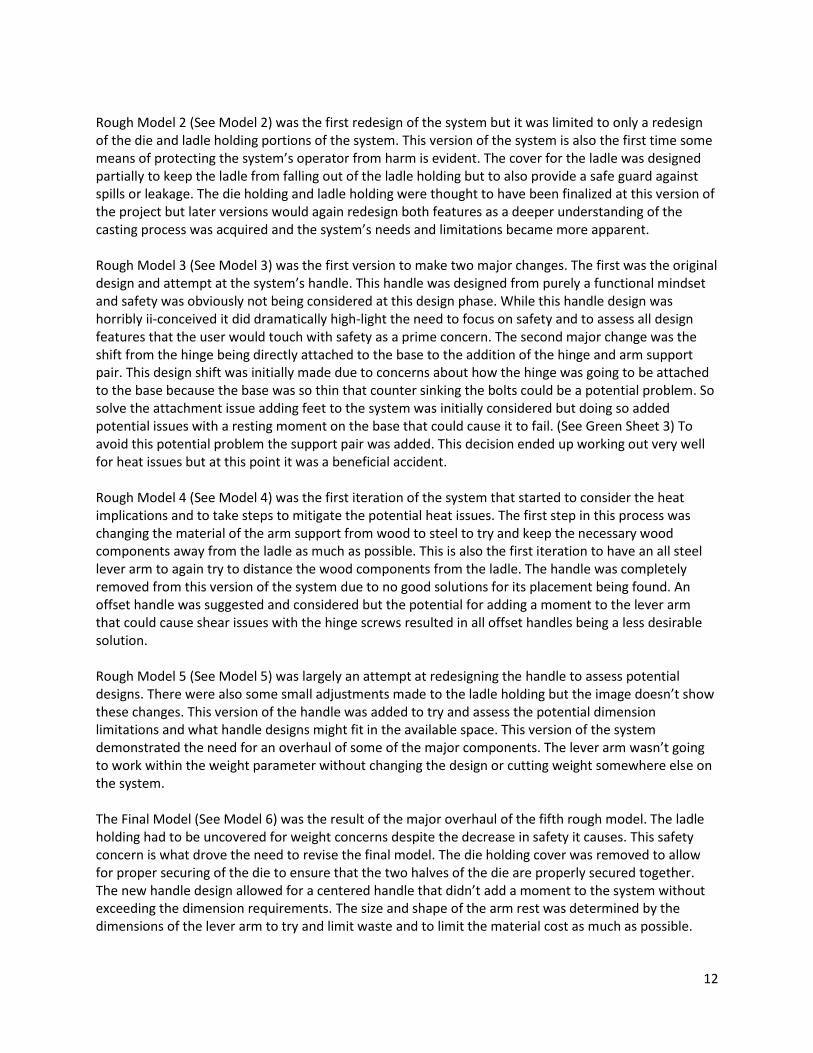
Rough Model 2 (See Model 2) was the first redesign of the system but it was limited to only a redesign of the die and ladle holding portions of the system. This version of the system is also the first time some means of protecting the system’s operator from harm is evident. The cover for the ladle was designed partially to keep the ladle from falling out of the ladle holding but to also provide a safe guard against spills or leakage. The die holding and ladle holding were thought to have been finalized at this version of the project but later versions would again redesign both features as a deeper understanding of the casting process was acquired and the system’s needs and limitations became more apparent. Rough Model 3 (See Model 3) was the first version to make two major changes. The first was the original design and attempt at the system’s handle. This handle was designed from purely a functional mindset and safety was obviously not being considered at this design phase. While this handle design was horribly ii-conceived it did dramatically high-light the need to focus on safety and to assess all design features that the user would touch with safety as a prime concern. The second major change was the shift from the hinge being directly attached to the base to the addition of the hinge and arm support pair. This design shift was initially made due to concerns about how the hinge was going to be attached to the base because the base was so thin that counter sinking the bolts could be a potential problem. So solve the attachment issue adding feet to the system was initially considered but doing so added potential issues with a resting moment on the base that could cause it to fail. (See Green Sheet 3) To avoid this potential problem the support pair was added. This decision ended up working out very well for heat issues but at this point it was a beneficial accident. Rough Model 4 (See Model 4) was the first iteration of the system that started to consider the heat implications and to take steps to mitigate the potential heat issues. The first step in this process was changing the material of the arm support from wood to steel to try and keep the necessary wood components away from the ladle as much as possible. This is also the first iteration to have an all steel lever arm to again try to distance the wood components from the ladle. The handle was completely removed from this version of the system due to no good solutions for its placement being found. An offset handle was suggested and considered but the potential for adding a moment to the lever arm that could cause shear issues with the hinge screws resulted in all offset handles being a less desirable solution. Rough Model 5 (See Model 5) was largely an attempt at redesigning the handle to assess potential designs. There were also some small adjustments made to the ladle holding but the image doesn’t show these changes. This version of the handle was added to try and assess the potential dimension limitations and what handle designs might fit in the available space. This version of the system demonstrated the need for an overhaul of some of the major components. The lever arm wasn’t going to work within the weight parameter without changing the design or cutting weight somewhere else on the system. The Final Model (See Model 6) was the result of the major overhaul of the fifth rough model. The ladle holding had to be uncovered for weight concerns despite the decrease in safety it causes. This safety concern is what drove the need to revise the final model. The die holding cover was removed to allow for proper securing of the die to ensure that the two halves of the die are properly secured together. The new handle design allowed for a centered handle that didn’t add a moment to the system without exceeding the dimension requirements. The size and shape of the arm rest was determined by the dimensions of the lever arm to try and limit waste and to limit the material cost as much as possible.

13
The revision of the final model (See Model 7) was just to add shielding to prevent heat issues. Each heat shield cuts the heat in half which will keep the base from reaching the auto-ignition combustion temperature and the operator from getting burned. (See Green Sheets 4 and 5) The hand shield also will serve to help keep any spills from getting to the operator’s hands.
7. CONCLUSION This project is a success because the system will demonstrate the die casting process with an open design that will allow for easy observation of all steps of the process. This project has all of the components of a successful senior project, Including:
1. An array of engineering merit from statics to casting to heat transfer. 2. A complete educational experience in managing a design to remain within the projects
constraints, budget, and time table. 3. A suitable level of technical challenge to demonstrate the designer’s skills and knowledge of
design techniques and processes.
8. ACKNOWLEDGEMENTS Dr. Craig Johnson – For tormenting me every step of the way for my own good. Matt Burvee – For keeping things real. Literally. It never would have been built without you. Professor Charles Pringle – For help with FEA and questioning all my analysis. Professor Daryl Fuhrman – For assisting in figuring out how to keep things from breaking. Professor Roger Beardsley – For helping me figure out how not to set things on fire. Joe Coupe – For the introduction to the world of casting.
9. REFERENCES Schleg, Frederick P., and Frederick H. Kohloff. Technology of Metalcasting. Des Plaines, IL: American Foundry Society, 2003. Print.
Mott, R. (2014). Machine elements in mechanical design (5th ed.). Upper Saddle River, N.J.:
Pearson/Prentice Hall.
Hibbeler, R. (2013). Statics and mechanics of materials (4th ed.). Upper Saddle River, N.J.:
Pearson/Prentice Hall.

14
10. APPENDIX A – Analyses
GREEN SHEET 1

15
GREEN SHEET 2

16
GREEN SHEET 3

17
GREEN SHEET 4

18
GREEN SHEET 5

19
GREEN SHEET 6

20
GREEN SHEET 7

21
GREEN SHEET 8

22
GREEN SHEET 9

23
Kinematic Sequence
FIGURE 2

24
FIGURE 3
FIGURE 4

25
11. APPENDIX B – Drawings A. Models i. Rough Model 1
MODEL 1

26
ii. Rough Model 2
MODEL 2

27
iii. Rough Model 3
MODEL 3

28
iv. Rough Model 4
MODEL 4

29
v. Rough Model 5
MODEL 5

30
vi. Final Model
MODEL 6

31
vii. Final Model Revision 1
MODEL 7

32
B. Drawings i. Rough Model 3 Drawings a. Base Drawing RM3-1
DRAWING 1

33
b. Lever Arm Rest RM3-2
DRAWING 2

34
c. Lever Arm RM3-3
DRAWING 3

35
d. Lever Arm Base RM3-4
DRAWING 4

36
e. Die-Holding Top RM3-5
DRAWING 5

37
f. Die-Holding Bottom RM3-6
DRAWING 6

38
ii. Final Model Drawings a. Base Drawing FM1
DRAWING 7

39
b. Arm Rest Drawing FM2
DRAWING 8

40
c. Hinge Support Drawing FM3
DRAWING 9

41
d. Die Holding Arm Drawing FM4
DRAWING 10

42
e. Handle Drawing FM5
DRAWING 11

43
f. Heat Shield Drawing FM6
DRAWING 12

44
g. Hand Shield Drawing FM7
DRAWING 13

45
iii. Assembly Drawings a. Base Assembly FMSA1
DRAWING 14

46
b. Lever Arm Assembly FMSA2
DRAWING 15

47
c. Complete Assembly FMA1
DRAWING 16

48
iv. Build Revision Drawings a. Base Drawing BRD-1
DRAWING 17

49
b. Arm Rest Drawing BRD-2
DRAWING 18

50
c. Hinge Support Drawing BRD-3
DRAWING 19

51
d. Die Holding Arm Drawing BRD-4
DRAWING 20

52
e. Handle Drawing BRD-5
DRAWING 21

53
f. Heat Shield Drawing BRD-6
DRAWING 22

54
g. Hand Shield Drawing BRD-7
DRAWING 23

55
12. APPENDIX C – Parts List Part Number Part Name Quantity
W1 Plywood Base 1
W2 Hinge Support 1
H1 Flat Butt Hinge 1
H2 #12 wood screws – 1 in 3
H3 #12 wood screws – 2 in 3
H4 C-Clamp 2
H5 ¼ - 28 Hex bolts – 1 in 5
H6 ¼ - 28 Hex bolts – 2 in 2
M1 Die Holding Arm 1
M2 Die Holding Rest 1
M3 Handle 1
A1 Casting Ladle 1
S1 Heat Shield 1
S2 Hand Shield 1
TABLE 3
13. APPENDIX D – Budget Part Name Relevant Dimensions Quantity Estimated Cost/Unit Actual Cost/Unit
Casting Ladle 2 oz ID = 3 in Depth = 1 ¼ in 1 $10 US $20
Flat Butt Hinge 1 in x 2 in 1 $10 US $7
#12 wood screws 1 in long 3 $.10 US Donated
#12 wood screws 2 in long 3 $.10 US Donated
¼ - 28 Hex Bolts 1 in long 5 $.10 US Donated
¼ - 28 Hex Bolts 2 in long 2 $.10 US Donated
2 x 4 wood 4 in long 1 $5 US Donated
Plywood .75 in thick 1 $12 US Donated
A36 flat bar 2in x 4 in x 1 ft long 1 $60 US $68
C-Clamp 3 in opening 2 $5 US
A36 Round Bar 1 in OD 2 ft long hot rolled
1 $7.20 US Donated
Rust-Oleum Black High Heat 1 $3.68 US Not Used
Galvanized Steel Sheet
Cold rolled 20 gauge 1ftx2ft
1 $10.84 US Donated
Estimated Total Cost $124.02 US $95
TABLE 4

56
14. APPENDIX E – Schedule A. Fall 2015 Schedule
FIGURE 5
Estimated Actual
1 Proposal
1a Introduction 2
1b Design & Analysis 30
1c Methods & Construction 10
1d Testing Method 5
1e Budget/ Schedule 10
1f Discussion 10
1g Conclusion 5
1h Model & Drawings 40
Rough Model 1
Rough Model 2
Rough Model 3
Rough Model 4
Rough Model 5
Final Model
Final Model Revision 1
1i Appendices 40
Appendix A
Appendix B
Appendix C
Appendix D
Appendix E
September October November DecemberTask ID DescriptionDuration (hr.)

57
B. Winter and Spring 2016 Schedule
FIGURE 6
Estimated Actual
1 Proposal
1j Finalize Design
1k Final Solidworks Model and Drawings
1l Final Proposal
2 Materials
2.1 Purchase Orders (Steel) 1 2/6
2.2 Acquire Wood 1 0.5
2.3 Purchase Hardware 1 1
3 Construction
3.1 Die Holding Arm
3.1.1 Check and Finalize Model 1 3
3.1.2 Create CNC Pathways 10 6
3.1.3 Verify CNC Pathways 2 2
3.1.4 Cut to Length 1 2
3.1.5 Horizontal Mill Corners 3 3
3.1.6 CNC Setup and Tooling Prep 3 1
3.1.7 Running CNC 10 7
3.1.8 Finishing Process 1 0.5
3.1.9 Side Milling 3 1
3.1.10 Drilling 3 4.5
3.2 Base
3.2.1 Cut to Size 0.5 1
3.2.2 Layout and Drill Holes 0.5 0.2
3.3 Hinge Support
3.3.1 Cut to Size 0.5 0.5
3.3.2 Layout and Drill Holes 0.5 0.2
3.4 Arm Rest
3.4.1 Cut to Size 1 0.5
3.4.2 Layout and Drill Holes 1 1.5
3.5 Handle
3.5.1 Cut to Size 0.5 1
3.5.2 Mill Notches 1 1
3.5.3 Drill 0.5 1
3.5.4 Bend 1 0
3.6 Heat Shield
3.6.1 Cut to Size 1 0.2
3.6.2 Cut and Bend Tabs 1 0.2
3.7 Hand Shield
3.7.1 Cut to Size 1 0.2
3.7.2 Drill 0.5 0
3.7.3 Bend 1 0.2
3.8 Assemble Pieces 3 1
3.9 Complete System
4 Other
4.1 Research / Meetings / Consultations 20 19
4.2 Paperwork 10 16
4.3 Unforeseen Manufacturing 5 3
Total Manufacturing 86.5 76.7
Estimated Actual
5 Testing
5.1 Website 20 8
5.2 SOURCE
5.2.1 Abstract 2 4
5.2.2 Poster 5 5
5.3 Physical Testing 4 7
5.4 Academic Testing 2
5.5 Testing Paperwork 1.5 2.5
5.6 Redesign and Side Project 10 16
5.7 Finalize All Material 10 4
April May June
April May JuneDuration (hr)
January February March
Task DescriptionDuration (hr)
January February March
Task Description

58
15. APPENDIX F – Testing Report Introduction: The testing period for the project will test the physical characteristics and abilities of the table top die cast system. This will include testing the physical requirements of the system like its weight, size, and functionality. The calculations and models of the system predict that the system should meet its size and weight requirements. All test data will be acquired using the procedures below and will obtained with the most precise tools available. Each individual test is expected to take an hour or two but they are spread out over s two eek period to allow time to deal with complications should they arise.
Method/Approach: Two of the three tests were designed to test only one requirement and variable to allow for simple straight forward testing. The third test will test multiple requirements and will be testing the functionality of the system as a whole. Accuracy of measurements will be limited by the tools available but the accuracy and precision of the available tools are adequate.
Test Procedure: Must weigh no more than 20lb. - Time (including prep, test, and cleanup): 1 hour - Location of Test: CWU Foundry - Test Actions: 1. Acquire: system, scale 2. Calibrate scale 3. Weigh the system with the scale 4. Record the weight of the system 5. Repeat steps 2 – 4 at least 3 times to ensure accuracy of measurements. - Risk/Safety: - The system does weigh an estimated 20lb, so if needed ask for assistance in lifting the system. - Discussion: The total weight of the system should be 20lb. This weight does not need to include the die or the ladle as these are peripheries for the system and can be transported separately if needed. - Conclusion The system is just barely less than the requirement at 19.9 lb. The system passes this requirement.
Must fit into a space no larger than 20in x 25in x 8in. - Time (including prep, test, and cleanup): 1 hour - Location of Test: CWU Foundry - Test Actions: 1. Acquire: system, accurate ruler/yardstick/tape measure, flat clean surface, marking device or
tape 2. Use accurate measuring device and pen or tape to mark out a 20 x 25 in square on the flat
clean surface. 3. Attempt to place the system in the marked out box. 4. Record whether the system can be placed within the limits of the box. 5. Measure and record the actual dimensions of the system including the height to check the 8
in requirement. - Risk/Safety: - The system does weigh an estimated 20lb, so if needed ask for assistance in lifting the system.

59
- Discussion: The total dimensions of the system can be greater than 20 x 25 in if the system can still be maneuvered so that it will fit into a 20 x 25 in square. The 8 in height requirement is unlikely to be met if the system is greater than 8 in tall with the lever arm down. - Conclusion The system failed to meet this requirement after the handle changes were made. Even though the system technically fails this requirement, where the system is going to be stored has changed. Instead of going in a cupboard the system now sits on its own little platform with its oven. The new location accommodates the increased size of the system. Figures 1 and 2 in the Appendix show an attempt at getting the system to fit into a space the size of the intended storage.
Pour test / must work with Aluminum. - Time (including prep, test, and cleanup): 3 hours - Location of Test: CWU Foundry - Test Actions: 1. Acquire: System, thermocouple, small crucible, aluminum, 2. Place the die in the system and C-clamp the die closed. 3. Place the thermocouple sensor on the wood base under the heat shield. 4. Melt the aluminum in the small crucible. 5. While the aluminum melts set up the thermocouple with the sensor below the heat shield. 6. Fill the ladle with the molten aluminum. 7. Tilt the lever arm slowly so that the aluminum pours from the ladle into the die. 8. Allow the die to sit until the aluminum in the die has solidified. - Risk/Safety: - The system does weigh an estimated 20lb, so if needed ask for assistance in lifting the system. - Proper PPE for handling molten metal is required. This will include but is not limited to gloves
and eye protection - Discussion: The remaining requirements are covered in this test. The thermocouple results are to demonstrate that the system is designed to handle the temperatures of the molten aluminum. - Conclusion The system failed the initial pour test. The liquid aluminum froze in the ladle. In an attempt to solve this issue the ladle will be warmed before the liquid aluminum is poured into it to try and prevent heat loss in the metal. The Temperature of the aluminum will also be increased from 1300 to 1600 or as high as the oven can manage. The Second pour test went much better. The procedure was amended to heat the ladle in the oven so that the heat in the ladle could help keep the metal flowing. The system didn’t pour perfectly but it serves as a perfect example of die casting and allows for students to get a close look at pouring and metal flow.
Deliverables: For the first test the deliverable will be three weight values after the system is weighed each time. The second test requires an overall measurement of the dimensions of the system and photographic proof that the system will fit into a space of the required dimensions. The third test will require a temperature value as well as a physical work piece. If no work piece is able to be produced then what was able to be produced will needed to be documented. An image of the workpiece or other end results are to be included with this document.

60
Appendix: Test Test Number Results
Weight 1 19.9 lb
Weight 2 19.9 lb
Weight 3 19.9 lb
Dimensions 1 14.25 x 32 x 5 in
Temperature 1 Initial Temp = 72.4 Final Temp = 75.2
FIGURE 7

61
FIGURE 8
16. Appendix G – Resume

62