Embed Size (px)
Citation preview

4
1
Tables/Explanations
Selection and Dimensioning Criteria, Hints on Application
Type/trademark 4/2Type, type designation 4/3
Approvals/standards 4/4Colour coding of fibre-optics 4/5
ApplicationInstallation of reeling cablesCentre feeding pointTransport of mining-type cables intounderground minesLaying instructions for OPTOFLEX(M)Stripping semiconductive layers fromPROTOLON trailing cables
Determination of the sag on mast mounting
4/64/84/94/10
4/11
4/124/13
Electrical parameters 4/14Thermal parameters 4/18
Mechanical parameters 4/20Chemical parameters 4/28
Design Features
Conductors 4/29Compounds 4/31
Shield 4/35Electrical field control with cables / hybrid sealing ends 4/36
Core arrangement 4/37
Support elements 4/39
Anti-torsion braid 4/39
Marking 4/40
l l l l l l l l l l l l l l l l l l l l l l l l l l l l l l l l l l
l l l l l l l l l l l

Pire
lliB
UIS
2.3
·200
0
Trademarks usedfor flexible electric cablesfor mining applications
Flexible cables
Special compounds
Type/trademark
4
2
CORDAFLEX®
OPTOFLEX®
PROTOLON®
PROTOMONT®
SUPROMONT®
LHD cable for scoop operations1 kV tough rubber-sheathed reeling cable(N)SHTÖU
Heavy tough rubber-sheathed flexiblecables (N)SHÖU, NSSHÖU,2YSLGCGÖU, NSSHCGEÖU
Medium-voltage mining-type cablesfor fixed installationNYHSSYCY, N3GHSSYCY
PROTODUR®
PROTOFIRM®
PROTOLON® Insulating compound EPR used inCORDAFLEX, PROTOLON, PROTOMONT.Rubber compound with excellent electricalproperties, resistant to heat and weather
Sheathing compound PCP used inCORDAFLEX, PROTOLON, PROTOMONT,compound with special resistance toabrasion and tearing, 5GM5 quality
Insulating compound PVCused in SUPROMONT cables
Rubber-sheathedflexible fibre-optic cable
Medium-voltage reeling cable, trailingcables, Medium-voltage flexible cables,R-(N)TSCGEWÖU F-(N)TSCGEWÖU,NTSCGEWÖU, NTMCGCWÖU

Pire
lliB
UIS
2.3
·200
0
4
3
Selection and Dimensioning Criteria
The type designates a group of flexible cables which have thesame design features and which are intended for a specific rangeof technical applications.The type designation is a letter combination in conformity withDIN VDE, which describes the type in coded form1).For details of the application, please refer to the applicationguidelines, table 4/3, page 4/6.
…K... Rubber cradle separator in the centre of thecable
KON Concentric protective conductor between theinner and outer sheath or concentric control/monitoring conductor
L... Lightweight cable design
LWL Fibre-optic (FO)
(M) Appendix to trademark, “M = Mining“
N Design according to the correspondingstandard
(N) Based on a standard
-O Additional information about the type - withoutgreen/yellow marked core
Ö1) Oil-resistant outer sheath (according toDIN VDE 0473, Part -2-1, Para. 10) (OE)
R- Definition of application: Reeling, as appendixto the type designation
(SB) Appendix to trademark:Trailing operation
..SH.. Heavy tough rubber-sheathed flexible min-ing-type cable (Rough handling)
..SHT... 1 kV reeling cable
..SL.. Control cable
ST Control cores within the cable
(ST) Appendix to trademark to denote watercompatibility (submersible pump units)
..T.. Support element
..TM.. Trailing cable for medium mechanical stresses
..TS.. Trailing cable
U Flame-retardant outer sheath (according toDIN VDE 0472, Part 804) “non-inflammable“
ÜL1) Monitoring conductor within the cable (UEL)
(V) Appendix to trademark for coal cutter cables(V = reinforced)
..W.. Weather resistant
Y PVC compound
(Z) Appendix to trademark for coal cutter cables(Z = tensile strength optimized)
2Y... Definition of the insulation material (2Y = PE)
/3 Protective-earth conductor uniformly distrib-uted in the three interstices
/3E Protective-earth conductor uniformly distrib-uted over the insulation of the outer conductor
..3G.. Definition of the insulating material (3G = EPR)
Type/type designation
NSHTÖU LHD cable for scoop operations:Tough rubber-sheathed 1kV flexible reelingcable CORDAFLEX (S)
R-(N)TSCGEWÖU Medium-voltage reeling cable, 6 to 30 kVPROTOLON (M)
F-(N)TSCGEWÖU Medium-voltage flexible cable, 6 to 30 kVPROTOLON (M)
NTSCGEWÖU Trailing cables PROTOLON, 3 to 35 kV
(N)SHÖU Heavy tough rubbers-sheathed flexible cable,1kV, for applications in open-cast mining,PROTOMONT (M)
NSSHÖU Heavy tough rubber-sheathed flexible cable,1kV, for applications in underground mining,PROTOMONT
NSSHCGEÖU Coal cutter cables for underground miningapplicationsPROTOMONT(Z) and PROTOMONT(V)
NTMTWÖU Heavy tough rubber-sheathed flexible cablefor lifts, user-operated winders in undergroundmining applications
NTMCGCWÖU Trailing cables of single-sheath design formedium mechanical stresses
NYHSSYCY PVC-insulated medium-voltage cables forfixed installation, SUPROMONT
N3GHSSYCY EPR-insulated medium-voltage cables forfixed installation, SUPROMONT
2YSLGCGÖU Data, signal and control cable for mininginstallations PROTOMONT MSR Mining
The type designation can be deciphered as follows:
..C.. Conducting metal casing over the strandedcores or between the inner and outer sheath(shield)
(C) Additional information about the shield for theconductor cross-sections, e.g. 12 x 1 (C)which means 1 mm² individually shielded or6 x (2 x 1)C which means 2 x 1 mm² twistedand shielded pairs
..CE.. Conducting metal casing over the insulation ofthe outer conductors
..CG.. Conducting non-metal casing over thestranded cores or between the inner andouter sheath (shield)
..CGE.. Conducting non-metal casing over the insula-tion of the outer conductors
F- Definition of the application: Fixed Installation,as supplement to the type designation
FM Telecommunication lines within the cable
G Rubber compound
HS High-voltage (H.V.)
-J Additional information about the type:with green/yellow marked core
1) The German characters “Ö” and “Ü” are transformedinto the international “OE” and “UE”, respectively

Pire
lliB
UIS
2.3
·200
0
Flexible electric cables for mining applications have to be able tocope with the expected operation and installation conditions.Details are given in the application and installation guidelines. In ad-dition, flexible electric cables for mining applications are describedwith regard to design and tests as laid down in national and inter-national standards (design regulations).
Application and installation guidelinesDIN VDE 0298, Part 3 Application of cables and flexible cords
in power installationsl General information on cables
DIN VDE 0298, Part 4 Application of cables and flexible cordsin power installationsl Recommended values for
current-carrying capacity of cablesDIN VDE 0101 Erection of power installations with rated
voltages above 1 kV
DIN VDE 0118 Specification for the erection of electricalinstallations in underground mines
DIN VDE 0168 Specification for the erection of electricalinstallations in open-cast mines, quarriesand similar works
IEC 621 Electrical installations for outdoor sitesunder heavy conditions (incl. open-castmines and quarries)
Design regulationsThe summary in table 4/1 (page 4/5) shows all the design regu-lations/standards, according to which the flexible electric cablesfor mining applications are designed and manufactured. Thefollowing distinctions are made between national and interna-tional regulations:National standardDIN VDE (DIN = German Standards Institute; VDE = Associa-tion of German Electrical Engineers)Germany is the only country which has issued special designregulations for flexible electric cables for mining applications.The 1 kV tough rubber-sheathed flexible reeling cablesCORDAFLEX NSHTÖU, the trailing cables PROTOLONNTS..WÖU and the rubber-sheathed flexible cables NSSHÖUare described and standardized in DIN VDE 0250. This set ofstandards has found recognition in Europe and in manycountries outside Europe and is accepted as or specified as“state of the art“.No such design regulations exist for the MSR Mining andOPTOPLEX cables. These are Pirelli special cables, the designof which is based on existing design regulations or general reg-ulations of DIN VDE.International standardFor use on an international level, some design features of flexi-ble electric cables for mining applications covered by DIN VDEare also listed or certified in line with MSHA.MSHA = Mine Safety and Health AdministrationThe MSHA listing was specially issued for the correspondingflexible electric cables by the “Deep Mine Safety“ office atHarrisburg, USA. The flame-retardant behaviour of the cableswas tested.WUG = Approval of the Polish Mining Inspectorate, necessaryfor use of cables in Polish mines.
4
4
Approvals/standards

Pire
lliB
UIS
2.3
·200
0
4
5
Selection and Dimensioning Criteria
Flexible cables Type German standard DIN VDE International standards
Table 4/1
Appovals/standards
CORDAFLEX (S)
OPTOFLEX (M)
PROTOLON (M)
PROTOLON (SB)
PROTOLON (ST)
PROTOMONT
PROTOMONT MSR Mining
PROTOMONT (Z)
PROTOMONT (V)
PROTOMONT (V)
NSHTÖU DIN VDE 0250, Part 814 MSHA P 189-3
Based on DIN VDE 0888 Based on FDDI, ISO/and DIN VDE 0168 IEC 9314, MSHA SC 189-1
(N)TSCGEWÖU Based on DIN VDE 0250, Part 813 MSHA P 189-4
NTSCGEWÖU DIN VDE 0250, Part 813 MSHA P 189-4WUG-GE 83/98
NTSCGEWÖU DIN VDE 0250, Part 813 MSHA P 189-4
NSSHÖU DIN VDE 0250, Part 812 MSHA P 189-3WUG-GE-104/97
2YSLGCGÖU Based on DIN VDE 0282, Part 4 WUG-GE 1/99
NSSHCGEÖU DIN VDE 0250, Part 812 MSHA P 189-3WUG-GE-68/97
NSSHCGEÖU DIN VDE 0250, Part 812 MSHA P 189-3WUG-GE-69/97
NTSKCGECWÖU DIN VDE 0250, Part 813 MSHA P 189-4WUG-GE-73/98
No. of fibres Fibre colours Buffering tube colours
6 x 1E9/125 OG/ BN / WH / RD / BK / YE 6 x nf
6 x 2E9/125 OG-PK / BN-PK / WH-PK / RD-PK /BK-PK / YE-PK
6 x nf
6 x 3E9/125 BU / OG / GN YE / BK/ / nf / nf / nf / nf
6 x 1G50/125 OG / GN / BN / WH / RD / BK 6 x nf
6 x 2G50/125 OG-PK / GN-PK / BN-PK / WH-PK /RD-PK / BK-PK
6 x nf
6 x 3G50/125 BU / OG / GN GN / BK / nf / nf / nf / nf
6 x 1G62.5/125 BU / OG / BN / WH / RD / BK 6 x nf
6 x 2G62.5/125 BU-PK / OG-PK / BN-PK / WH-PK /RD-PK / BK-PK
6 x nf
6 x 3G62.5/125 BU / OG / GN BU / BK / nf / nf / nf / nf
Table 4/2
nf = natural colouringBold-faced colour codings areindices relative to the fibre type
Monomode design E9/125 µm
Graded-index fibre design G50/125 µm
Graded-index fibre design G62.5/125µm
Colour coding of fibre-optics
PROTOMONT (M) (N)SHÖU Based on DIN VDE 0250, Part 812 MSHA P 189-3

4
6
Flexible cables/application
Flexible reeling cable suitable for very high mechanical stresses inconjunction with mono spiral reels and cylindrical reels
CORDAFLEX (S)
For optical transmission of signals and data for material handling equip-ment and alongside belt conveyors
OPTOFLEX (M)
PROTOLON (M) R-(N)TSCGEWÖU
Flexible reeling cable suitable for high mechanical stresses, e.g. for ex-cavators, hoisting equipment and large mobile equipment
PROTOLON (ST)
Flexible medium-voltage cable for trailing operation for power supply tolarge mobile equipment in open-cast mines, in particular where the outersheath is subjected to extreme abrasion and chaffing stresses
PROTOLON (M) F-(N)TSCGEWÖU
Flexible medium-voltage cable, e.g. for laying alongside belt conveyorsand on material handling equipment
PROTOLON single-core cables
Medium-voltage cable for flexible applications, e.g. for connection ofswitchgear cubicles and for connection of transformers
Data, signal and control cables for mining installations for applicationswith high mechanical stresses in open-cast mines, e.g. for laying along-side conveyor belts and on material handling equipment
PROTOMONT (M) MSR data, signal and control cables
Flexible rubber-sheathed cable for very high mechanical stresses, e.g. forpower supply of fixed installation equipment such as machines, motors,distribution boards and equipment in underground mines
PROTOLON (SB)
Flexible medium-voltage cable for continuous use in water, e.g.for power supply to dredgers or pumps
PROTOMONT
Coal cutter trailing cable for free trailing in underground mines for powersupply of coal cutters
PROTOMONT (V)
Coal cutter cable for use in the cable protection chain for power supplyto coal cutters in underground mines
PROTOMONT (Z)
SUPROMONT
Flexible medium-voltage cable for fixed installation in underground minesand tunnel construction applications
PROTOMONT mine hoist cables
Flexible special control and signalling cable for connection ofuser-operated hoists (user-operated winders) in underground mines forfree suspension lengths of up to 200 m
Medium-voltage reeling cable with overall concentric monitoring shieldaccording to DIN VDE 0118 for power supply of tunnel driving machines
PROTOMONT tunnel driving machine cables
Application
PROTOMONT (M)
Flexible rubber-sheathed cable for very high mechanical stresses, e.g.for laying alongside belt conveyors and on material handling equipmentin open-cast mines
l Normal applicationTable 4/3
Flexible electric cables for underground andopen-cast mining applications are to be se-lected in accordance with the application forwhich they are intended (cable guidance sys-tem) and in accordance with the expectedoperation and installation conditions.If necessary, the cables are to be protectedagainst mechanical, thermal or chemical influ-ences and also against the penetration ofmoisture from the ends of the cables.Flexible electric cables for mining applicationsmust not be installed in the ground. Ductsthrough fire barriers in the form of sand, etc,or temporary covering with soil, sand or simi-lar material, e.g. on construction sites and inopen-cast mines, do not count as being inthe ground.In general, fixing materials must not damagethe flexible electric cables.Flexible electric cables have to be relieved oftension when they are connected to mobileequipment and must be secured to preventthem from twisting, sharp bending and axialcompression. The sheaths of the flexible elec-tric cables must not be damaged at the en-tries or by the stress-relief devices.Table 4/3 shows the mechanical stressabilityand the normal applications of flexible electriccables for mining applications.

4
7
l
l
l
l
l
l
l l l l l l
l l l l l
l l l l l l
l l
l l l l l l
l l l l l
Yes
Yesfor trailing operation
l
l
l l l
l
l
ll
l l l l l l l
l
l
l l Yes
l
l l l l
l
l l l l l
Yes
l
l Yesin lift systems
l l l l l l
l l l l l
Yesfor chain operation
l l l l l l ll
Yesfor trailing operation
l l l l l l l l
l ll l lllll
l l l l lll
Selection and Dimensioning Criteria
Mechanical stress Forced guidance Application
Medium High Veryhigh(extreme)
Outdoors Hazard-ousareas
Construc-tionsites
Indoors Mobileequip-ment &machinery
Open-cast
Under-ground
l l l l l l ll
l
Mining

Pire
lliB
UIS
2.3
·200
0
The direction of lay employed in manufac-ture of power cables is always left-hand(S-type). It is therefore recommended thatthe start of the winding of reeling powercables on cylindrical reels should alwaysbe at the left side.This measure ensures a clean and correctwinding pattern, even when no guidancehelical slot has been provided on the reelbody.The direction of lay employed in manufac-ture of control cables is alwaysright-hand, for which reason such cablesshould be operated with the start of thewinding at the right side.
4
8
Installation of reeling cables
Incorrect Correct
Supply drum Supply drum
Supply drum Supply drum
Incorrect Correct
Fig. 4/1
Fig. 4/2 Start of winding for power cables
To ensure proper and fault-free operationof flexible electric reeling cables for miningapplications such as PROTOLON andCORDAFLEX, it is necessary to observecertain rules for cable attachment (installa-tion on the operating drum).The cable can be directly wound from thesupply drum to the operating drum. Pullingoff the drum and laying stretched on theground or “dekinking“ prior to taking upthe cable on the operating drum shouldnot be carried out.

Pire
lliB
UIS
2.3
·200
0
In many installations, e.g. bunk-ering equipment, the powerinfeed point is located at thecentre of the guideway. Theflexible electric reeling cablessuch as CORDAFLEX andPROTOLON (M)-R are normallyconnected through underfloorinfeeds (Fig. 4/3).In order to achieve effectivestrain relief in conjunction withcable-wear minimizing deflec-tion from the infeed point, werecommend the use of un-derfloor infeeds (Fig. 4/4). It isimportant that the specifiedbending radius be maintainedand that the cable be fastenedat the compensation cylinder bymeans of a clip, which, how-ever, should be attached onlyafter the 2nd winding.
Min. permissible bending radius as a function of the cable diameter
Flexible cables CORDAFLEX PROTOLON
Rated voltage U0/U Up to 0.6/1 kV Above 0.6/1 kV
d in mm Up to 8 Above 8 to 12 Above 12 to 20 Above 20
Rmin 3 x d 4 x d 5 x d 5 x d 10 x d
Table 4/4
Fig. 4/3
1 Flexible electric reeling cable
2 Entry bell for infeed
3 Cable tray
4 Cable straight-through joint
5 Buried cable
6 Compensation cylinder
7 Cable clip (large area design)
d Max. cable diameter
Rmin Bending radius of entry bell andbending radius of compensationcylinder
Selection and Dimensioning Criteria
Centre feeding point
4
9
Fig. 4/4
BU
IS_0
77.ti
f

Pire
lliB
UIS
2.3
·200
0
4
10
In view of the tight and narrow conditions which exist in undergroundmines, transport of mining-type cables into such underground minesrequires special handling. In cases where, due to the large diameter,the cable cannot be transported on the supply drum to the vicinity ofthe longwall, transport must be effected using transport containers.For this purpose the cable is laid into the transport container in “8"shaped loops (Fig. 4/5).In the case of PROTOMONT (Z) and PROTOMONT (V) coal cutter ca-bles in particular, no torsional stress may be applied to the cable whenpulling it out, since thiswould have a negativeeffect on the operatingperformance and ser-vice life of the cable. Forthis reason the cablemust be pulled out be-ginning at the insertionend and care must betaken to ensure that noloops are formed, whichon further pulling of thecable could lead totwisting of the cable.In addition care must betaken to ensure that thebending radius ismaintained and that thepermissible tensileforces are not exceededon transportation to thelongwall. The bestmethod for stress-minimizing is to carrythe cable by hand, al-though this is the mostcumbersome method.
Fig. 4/5
Transport of mining-type cables into underground mines
BU
IS_0
65.ti
f
Pire
lliB
UIS
2.3
·200
0
Selection and Dimensioning Criteria 4
11
Laying instructions for OPTOFLEX (M) cables
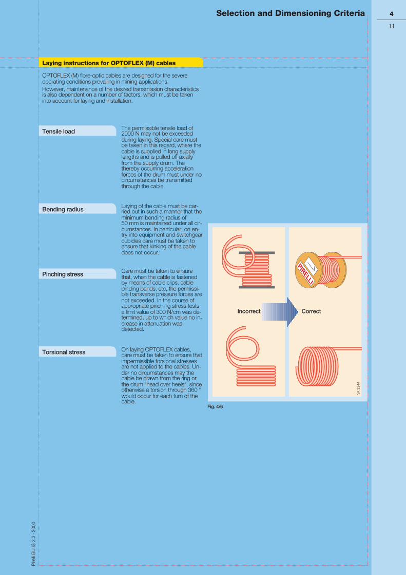
OPTOFLEX (M) fibre-optic cables are designed for the severeoperating conditions prevailing in mining applications.However, maintenance of the desired transmission characteristicsis also dependent on a number of factors, which must be takeninto account for laying and installation.
The permissible tensile load of2000 N may not be exceededduring laying. Special care mustbe taken in this regard, where thecable is supplied in long supplylengths and is pulled off axiallyfrom the supply drum. Thethereby occurring accelerationforces of the drum must under nocircumstances be transmittedthrough the cable.
Laying of the cable must be car-ried out in such a manner that theminimum bending radius of50 mm is maintained under all cir-cumstances. In particular, on en-try into equipment and switchgearcubicles care must be taken toensure that kinking of the cabledoes not occur.
Care must be taken to ensurethat, when the cable is fastenedby means of cable clips, cablebinding bands, etc, the permissi-ble transverse pressure forces arenot exceeded. In the course ofappropriate pinching stress testsa limit value of 300 N/cm was de-termined, up to which value no in-crease in attenuation wasdetected.
On laying OPTOFLEX cables,care must be taken to ensure thatimpermissible torsional stressesare not applied to the cables. Un-der no circumstances may thecable be drawn from the ring orthe drum “head over heels“, sinceotherwise a torsion through 360 °would occur for each turn of thecable.
Tensile load
Bending radius
Pinching stress
Torsional stress
PIRELLI
PIRELLI
Incorrect Correct
Fig. 4/6
Pire
lliB
UIS
2.3
·200
0
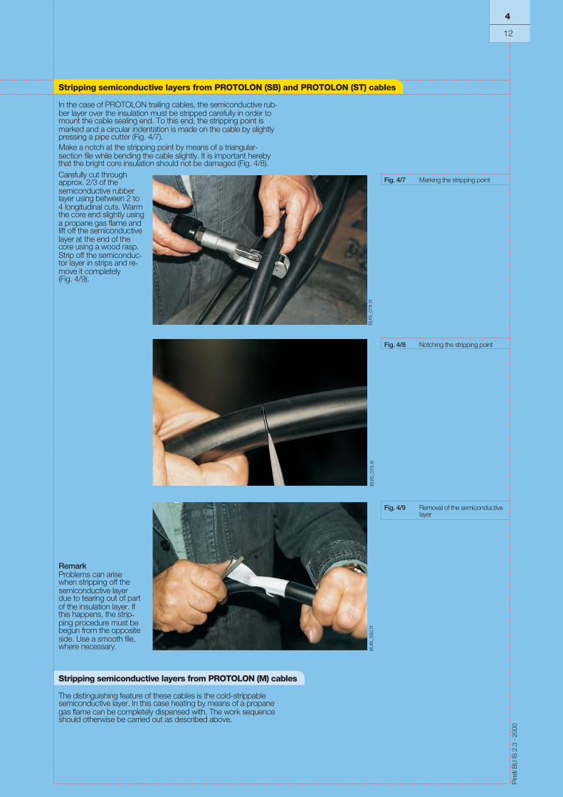
In the case of PROTOLON trailing cables, the semiconductive rub-ber layer over the insulation must be stripped carefully in order tomount the cable sealing end. To this end, the stripping point ismarked and a circular indentation is made on the cable by slightlypressing a pipe cutter (Fig. 4/7).Make a notch at the stripping point by means of a triangular-section file while bending the cable slightly. It is important herebythat the bright core insulation should not be damaged (Fig. 4/8).Carefully cut throughapprox. 2/3 of thesemiconductive rubberlayer using between 2 to4 longitudinal cuts. Warmthe core end slightly usinga propane gas flame andlift off the semiconductivelayer at the end of thecore using a wood rasp.Strip off the semiconduc-tor layer in strips and re-move it completely(Fig. 4/9).
RemarkProblems can arisewhen stripping off thesemiconductive layerdue to tearing out of partof the insulation layer. Ifthis happens, the strip-ping procedure must bebegun from the oppositeside. Use a smooth file,where necessary.
Stripping semiconductive layers from PROTOLON (M) cables
The distinguishing feature of these cables is the cold-strippablesemiconductive layer. In this case heating by means of a propanegas flame can be completely dispensed with. The work sequenceshould otherwise be carried out as described above.
Fig. 4/7 Marking the stripping point
Fig. 4/8 Notching the stripping point
Fig. 4/9 Removal of the semiconductivelayer
Stripping semiconductive layers from PROTOLON (SB) and PROTOLON (ST) cables
4
12
BU
IS_0
78.ti
fB
UIS
_079
.tif
BU
IS_0
80.ti
f
Pire
lliB
UIS
2.3
·200
0
Selection and Dimensioning Criteria 4
13
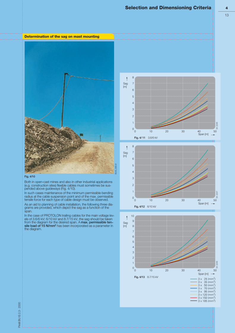
Both in open-cast mines and also in other industrial applications(e.g. construction sites) flexible cables must sometimes be sus-pended above guideways (Fig. 4/10).In such cases maintenance of the minimum permissible bendingradius at the cable suspension point and of the max. permissibletensile force for each type of cable design must be observed.As an aid to planning of cable installation, the following three dia-grams are provided, which depict the sag as a function of thespan.In the case of PROTOLON trailing cables for the main voltage lev-els of 3.6/6 kV; 6/10 kV and 8.7/15 kV, the sag should be takenfrom the diagram for the desired span. A max. permissible ten-sile load of 15 N/mm2 has been incorporated as a parameter inthe diagram.
Sag[m]
Span [m]Fig. 4/ 11 3.6/6 kV
Sag[m]
Span [m]Fig. 4/12 6/10 kV
Sag[m]
Span [m]Fig. 4/13 8.7/15 kV
Fig. 4/10
Determination of the sag on mast mounting
BU
IS_0
66.ti
f

Pire
lliB
UIS
2.3
·200
0
Flexible cables Rated Max. permissible operating voltage Test voltage applied to the complete cable
voltage in in DC systems
U0/U
AC systems
U0/U
unearthed
UkV
single-phaseearthedUkV
Powercores
kV
Controlcores
kV
Pilotcores
kV
Tele-comm.coreskV
250/250 V 275/275 V 0.412 1.5
300/500 V 318/550 V 0.825 0.413 2
450/750 V 476/825 V 1.238 0.619 2.5
0.6/1 kV 0.7/1.2 kV 1.8 0.9 2.5 2
0.6/1 kV 0.7/1.2 kV 1.8 0.9 4 2 2 1
1.8/3 kV 2.1/3.6 kV 5.4 2.7 6 2 2 1
3.6/6 kV 4.2/7.2 kV 10.8 5.4 11 2 2 1
6/10 kV 6.9/12 kV 18 8 17 2 2 1
8.7/15 kV 10.4/18 kV 27 14 24 2 2 1
12/20 kV 13.9/24 kV 36 18 29 2 2 1
14/25 kV 17.3/30 kV 45 23 36 2 2 1
18/30 kV 20.8/36 kV 54 27 43 2 2 1
Table 4/5 20/35 kV 24.3/42 kV 63 32 50 2 2 1
4
14
Electrical parameters
CORDAFLEX, PROTOMONT (M)
PROTOMONT MSR-Mining
PROTOLON (M)
PROTOLON (SB)
PROTOLON (ST)
PROTOLON 1-core
SUPROMONT
PROTOMONT tunnel driving
VoltagesFor the rated, operating and test voltages of cables, the defini-tions given in DIN VDE 0298, Part 3, apply. Some of these arementioned in table 4/5 below.
AC - alternating currentDC - direct current
Rated voltageThe rated voltage of an insulated electric cable is the voltagewhich is used as the basis for the design and the testing of thecable with regard to its electrical characteristics.The rated voltage is expressed by the two values of power fre-quency voltage U0/U in V.U0 rms value between one conductor and “earth“U rms value between two conductors of a multi-core cable
or of a system of single-core cablesIn a system with AC voltage, the rated voltage of a cable must beat least equal to the rated voltage of the system for which it isused. This requirement applies both to the value U0 and thevalue U.In a system with DC voltage, its rated voltage must not be morethan 1.5 times the value of the rated voltage of the cable.
Operating voltageThe operating voltage is the voltage applied between the con-ductors and earth of a power installation with respect to time andplace with trouble-free operation.
l Cables with a rated voltage U0/Uup to 0.6/1 kVThese cables are suitable for use in three-phase AC, sin-gle-phase AC and DC installations, the maximum continuouslypermissible operating voltage of which does not exceed the ratedvoltage of the cables by more than
l 10% for cables with a rated voltage U0/U up to and including450/750 V20% for cables with a rated voltage U0/U = 0.6/1 kV.
l Cables with a rated voltage U0/Ugreater than 0.6/1 kVThese cables are suitable for use in three-phase and sin-gle-phase AC installations, the maximum operating voltage ofwhich does not exceed the rated voltage of the cable by morethan 20%.
l Cables in DC installationsIf the cables are used in DC installations, the continuously per-missible DC operating voltage between the conductors must notexceed 1.5 times the value of the permissible AC operating volt-age. In single-phase earthed DC installations, this value shouldbe multiplied by a factor of 0.5.
Test voltageRegarding the test voltage of flexible cables, the values given inthe corresponding parts of DIN VDE 0250 apply. If the relevantshield is missing, as for example with CORDAFLEX andPROTOMONT cables,”core against core” is tested in appropriatecombinations. The values are to be regarded as AC test voltages(unless stated otherwise) for single-phase testing, i.e. the AC testvoltage is applied between the core and the correspondingshielding (e.g. semiconductive layer, earth conductor, shield).Telecommunication cores (pairs) and other shielded pairs (e.g.(2x1)C) are tested “core against core“ and “core against shield“whereby the test voltages are correspondingly different.With single-core cables without shielding, the correspondingopposite pole is a water bath.

Pire
lliB
UIS
2.3
·200
0
4
15
CORDAFLEX (S)
PROTOLON, SUPROMONT rubber up to 10 kV
PROTOMONT
Selection and Dimensioning Criteria
Current-carrying capacityIf, after all selection criteria have been taken into account, the type offlexible electric cable to be used for mining applications has been de-cided on, the necessary cross-section of the conductor can be de-termined either from the current to be transmitted or from the power.
Installation conditions (stretched laying, suspended freely in theair, reeled), variations in ambient temperature, grouping, type ofoperation (continuous duty, intermittent periodic duty) and theuse of multi-core cables are to be taken into account.Table 4/6 is valid for continuous duty at 30 °C ambient tempera-ture and three loaded cores, rubber-insulated or PVC-insulatedcables.
Rubber-insulated
Cross-section Stretched Suspended Reeled in
mm2layingA
freely in airA
1 layerA
2 layersA
3 layers1)
A4 layersA
5 layersA
6 layersA
7 layersA
Factor 1 1.05 0.8 0.61 0.49 0.42 0.38 0.27 0.22
1 18 19 14 11 9 8 7 5 4
1.5 23 24 18 14 11 10 9 6 5
2.5 30 32 24 18 15 13 11 8 7
4 41 43 33 25 20 17 16 11 9
6 53 56 42 32 26 22 20 14 12
10 74 78 59 45 36 31 28 20 16
16 99 104 79 60 49 42 38 27 22
25 131 138 105 80 64 55 50 35 29
35 162 170 130 99 79 68 62 44 36
50 202 212 162 123 99 85 78 55 44
70 250 263 200 153 123 105 95 68 55
95 301 316 241 184 147 126 114 81 66
120 352 370 282 215 172 148 134 95 77
150 404 424 323 246 198 170 154 109 89
185 461 484 369 281 226 194 175 124 101
240 540 567 432 329 265 227 205 146 119
300 620 651 496 378 304 260 236 167 136
16 105 84 64 51 44 40 28 23
25 139 111 85 68 58 53 38 31
35 172 138 105 84 72 65 46 38
50 216 172 131 105 90 82 58 47
70 265 212 162 130 111 101 72 58
95 319 255 195 156 134 121 86 70
120 371 297 226 182 156 141 100 82
150 428 342 261 210 180 163 116 94
185 488 390 298 239 205 185 132 107
240 574 459 350 281 241 218 155 126
300 660 528 403 323 277 251 178 145
PVC-insulated PE-insulated 1) The reduction factor is also valid for flatreeling cables (spirally)
25 96 2 x 2 x 1 12
35 119 5 x 2 x 1 8.5
50 144 10 x 2 x 1 6.5
70 184 20 x 2 x 1 5Table 4/6Current-carrying capacity of flexible electriccables for mining applications
95 223
120 259
PROTOMONT, PROTOLON, SUPROMONT rubber from 15 kV
Electrical parameters
SUPROMONT PVC MSR-Mining

Pire
lliB
UIS
2.3
·200
0
De-rating factorsThe de-rating factors take into account the installation and op-erating conditions, such as temperature, grouping, intermittentperiodic duty and the number of simultaneously loaded cores.They are to be used for determining the current-carrying capac-ity in accordance with table 4/6 (page 4/15).
De-rating factors for varying ambient temperatures
Flexible cables Ambient temperature °C
10 15 20 25 30 35 40 45 50 55 60 65 70
1.18 1.14 1.10 1.05 1.00 0.95 0.89 0.84 0.77 0.71 0.63 0.55 0.45
1.18 1.14 1.10 1.05 1.00 0.95 0.89 0.84 0.77 0.71 0.63 0.55 0.45
1.18 1.14 1.10 1.05 1.00 0.95 0.89 0.84 0.77 0.71 0.63 0.55 0.45
1.18 1.14 1.10 1.05 1.00 0.95 0.89 0.84 0.77 0.71 0.63 0.55 0.45
1.22 1.17 1.12 1.06 1.00 0.94 0.87 0.79 0.71 0.61 0.50
Table 4/7
CORDAFLEX
PROTOMONT
SUPROMONT rubber
PROTOLON
SUPROMONT PVC
De-rating factors for groupingArrangement Number of multi-core cables or number of single or three-phase circuits made
up of single-core cables (2 or 3 loaded conductors)
1 2 3 4 5 6 7 8 9 10 12 14 16 18 20Bunched directly at thewall, the floor, in conduitor ducting, on or in thewall
1.0 0.8 0.7 0.65 0.6 0.57 0.54 0.52 0.5 0.48 0.45 0.43 0.41 0.39 0.38
Single layer on the wallor floor, touching
1.0 0.85 0.79 0.75 0.73 0.72 0.72 0.72 0.71 0.70
Single layer on the wall orfloor, spaced with aclearance of 1 x cablediameter between adja-cent cables
1.0 0.94 0.9 0.9 0.9 0.9 0.9 0.9 0.9 0.9 0.9 0.9 0.9 0.9 0.9
Single layer under ceiling,touching
0.95 0.81 0.72 0.68 0.66 0.64 0.63 0.62 0.61
Single layer under ceiling,spaced with a clearanceof 1 x cable diameterbetween adjacent cables
0.95 0.85 0.85 0.85 0.85 0.85 0.85 0.85 0.85 0.85 0.85 0.85 0.85 0.85 0.85
Table 4/8
= ===
= =
4
16
Electrical parameters

Pire
lliB
UIS
2.3
·200
0
4
17
De-rating factors for multi-core cables with conductor cross-sections up to 10 mm2
Number ofloadedcores
De-ratingfactors
5 0.75
7 0.65
12 0.53
18 0.44
24 0.40
30 0.37
36 0.36
42 0.35
61 0.30
Table 4/10
De-rating factors for intermittent periodic duty
Ambienttemperature 30 °C
Nominalcross-section
Duty factor ED %
mm2 60 40 25 15
Duty cycle 10 min 0.75 1.00 1.00 1.00 1.00
1 1.00 1.00 1.00 1.00
1.5 1.00 1.00 1.00 1.00
2.5 1.00 1.00 1.04 1.07
4 1.00 1.03 1.05 1.19
6 1.00 1.04 1.13 1.27
10 1.03 1.09 1.21 1.44
16 1.07 1.16 1.34 1.62
25 1.10 1.23 1.46 1.79
35 1.13 1.28 1.53 1.90
50 1.16 1.34 1.62 2.03
70 1.18 1.38 1.69 2.13
95 1.20 1.42 1.74 2.21
120 1.21 1.44 1.78 2.26
150 1.22 1.46 1.81 2.30
185 1.23 1.48 1.82 2.32
240 1.23 1.49 1.85 2.36
300 1.23 1.50 1.87 2.39
Table 4/9
De-ratingfactor
Number of simultaneously loaded cores
Permissible short-circuit current at max. permissible short-circuit temperatures of the conductor surface and for a fault duration tkr = 1 s
Cross-section mm2 1 1.5 2.5 4 6 10 16 25 35 50 70 95 120 150 185 240 300
Short-circuit current (kA)
0.122 0.183 0.305 0.488 0.732 1.22 1.952 3.05 4.27 6.10 8.54 11.59 14.64 18.30 22.57 29.28 36.60
0.143 0.215 0.358 0.572 0.858 1.43 2.29 3.58 5.01 7.15 10.01 13.6 17.16 21.45 26.46 34.32 42.9
0.109 0.164 0.273 0.436 0.654 1.109 1.744 2.73 3.82 5.45 7.63 10.36 13.08 16.35 20.17 26.16 32.7
Table 4/11
PROTOLON (M)
SUPROMONT PVC
Selection and Dimensioning Criteria
Electrical parameters
CORDAFLEX
PROTOMONT
PROTOLON (SB)
PROTOLON (ST)
SUPROMONT rubber
The short-circuit current-carrying capacity Ithzfor a short-circuit duration tk deviating from tkr = 1s, is: Ithz = Ithr ⋅ ttkr
k

Pire
lliB
UIS
2.3
·200
0
The different temperature limits of the individual flexible electriccables for mining applications are summarized in table 4/12.Under no circumstances may the values shown be exceededdue to interaction of internal Joule heat and the ambient tem-perature.If cables are exposed to radiation, e.g. sunlight, the temperatureof the outer sheath of the flexible electric cable can rise to a levelwhich is significantly higher than the ambient temperature. Thissituation must be compensated for by corresponding reductionof the current-carrying capacity.The temperatures on the surface of the cable are limits for theambient temperature.
All insulating and sheathing compounds of the flexible electric ca-bles become stiffer as the temperature drops. If the temperaturefalls below the specified limit, a point can be reached below whichthe compounds used become brittle.In addition to this, more force (sometimes considerably more) isneeded for bending a flexible electric cable due to the increase ofstiffness of the insulating and sheathing compounds at lowertemperatures. This can create problems in the use of the flexibleelectric cables (e.g. with the reel drive).
Temperature limits
Flexible cables Type Temperature limit during operation, storage, installation and transport (°C)
of the conductorduring operation
of the conductorduring short-circuit
on the surface of thecable,fixed installation
on the surface of thecable, fullyflexible installation
(N)TSCGEWÖU 90 250 – 40 to + 80 – 25 to + 60
NTSCGEWÖU 90 200 – 40 to + 80 – 20 to + 60
NTSCGEWÖU 90 200 – 40 to + 80 – 25 to + 60
NTMCGCWÖU 90 200 – 40 to + 80 – 25 to + 60
(N)SHÖU 90 250 – 40 to + 80 – 25 to + 60
NSSHÖU 90 200 – 40 to + 80 – 25 to + 60
– – – 40 to + 80 – 30 to + 60
2YSLGCGÖU 60 150 – 40 to + 60 – 25 to + 60
NSSHCGEÖU 90 200 – 40 to + 80 – 20 to + 60
NTMTWÖU 90 200 – 40 to + 80 – 25 to + 80
NYHSSYCY 70 150 – 40 to + 60 + 5 to + 60
N3GHSSYCY 90 250 – 40 to + 80 + 5 to + 80
NSHTÖU 90 200 – 40 to + 80 – 25 to + 60
Table 4/12
PROTOLON (M)
PROTOLON (SB)
PROTOLON (ST)
PROTOLON 1-core
PROTOMONT
OPTOFLEX
PROTOMONT MSR
Thermal parameters
4
18
PROTOMONT (Z) and (V)
PROTOLON mine hoist
SUPROMONT PVC
CORDAFLEX (S)
SUPROMONT rubber
PROTOMONT (M)

Pire
lliB
UIS
2.3
·200
0
The relationship between the bending stiffness of flexible electric cables formining applications and the temperature is shown in Fig. 4/14.The ratio of the bending force is given as F/F0, withF0 = F20 ºC.
The temperature limits on the surface of the cable are specified to ensureproblem-free and healthy operation during forced guidance of flexible electriccables for mining applications, especially while trailing over ground and dur-ing reeling operation.Higher temperatures influence the hardness, abrasion, resistance to tearpropagation and the transverse pressure stability of the insulating andsheathing compounds and can thus lead to a reduction of their service life.Flexible electric cables should be selected, installed and operated so that theexpected dissipation of Joule heat is not hindered in any way and thereforeno risk of fire is incurred.
4
19
Fig. 4/14
Selection and Dimensioning Criteria
Thermal parameters
dL = Overall cable diameterF = Force
RatioofbendingforceF/F0
Bending temperature (°C)

Pire
lliB
UIS
2.3
·200
0
Tensile loadsThe tensile loads of copper conductors in flexible electric cables for mining applications as specified byDIN VDE 0298, Part 3, should not exceed 15N/mm². However, higher values are allowed for some ca-bles as shown in table 4/13. These values refer to tensile load only.
These maximum permissible limits of tensile load are to be regarded as the sum of the static and dy-namic loads.
When the permissible tensile force is being calculated, shields, concentric conductors and split protec-tive-earth conductors as well as integrated control cores and monitoring cores of power cables mustnot be included in the calculation.
For higher tensile loads, appropriate steps have to be taken such as increasing the bending radii orusing special cable designs with stress relieving support elements. In some cases, a shorter service lifecan be expected. In this case, the cable manufacturer should be consulted.
The maximum permissible tensile load for installing fixed laying flexible cables is 50 N/mm² referredto the cross-section of the conductor.
Flexible cables Type DIN VDEN/mm2
PirelliN/mm2
R-(N)TSCGEWÖU 15 20
F-(N)TSCGEWÖU 15 15
NTSCGEWÖU 15 15
NTSCGEWÖU 15 15
NTMCGCWÖU 15 15
(N)SHÖU, NSSHÖU 15 15
– 2000 N for the cable
2YSLGCGÖU 15 15
NSSHCGEÖU 15 > 40 kN breaking load of thebraid
NSSHCGEÖU 15 15
NTMTWÖU 15 Max. 200 m free suspensionlength
NYHSSYCY,N3GHSSYCY
15 15
NSHTÖU 15 30
Table 4/13
PROTOLON (M)
PROTOLON (M)
PROTOLON (SB)
PROTOLON (ST)
PROTOLON 1-core
PROTOMONT
PROTOMONT (Z)
PROTOMONT MSR-Mining
PROTOMONT (V)
PROTOMONT mine hoist cable
SUPROMONT PVC and rubber
OPTOFLEX (M)
CORDAFLEX (S)
Maximum tensile loadsduring installation and op-eration of flexible electriccables for mining applica-tions
4
20
Mechanical parameters

Pire
lliB
UIS
2.3
·200
0
Torsional stressesAs a general rule the torsional stresses occurring during operation of flexible electric cables for min-ing applications are low. In certain applications, such as for example laying on large mobile equip-ment (cable booms), torsional stresses are unavoidable.The maximum permissible torsional stresses which occur during operation at entries, slewing gears,windmills, etc., are summarized in table 4/14.If the limits are exceeded, this can lead to a reduction in service life. In critical cases, the cablemanufacturer should be consulted.Torsional stresses created by the systems involved (e.g. due to misalignment of cable guidance sys-tems, oblique cable pay out) should be avoided and are not included here.
Selection and Dimensioning Criteria
Maximum torsionalstresses during operationof flexible electric cablesfor mining applications
Flexible cables Type α (°/m)
With semiconductiverubber layer
With copper coreshield
(N)TSCGEWÖU ± 100 –
NTSCGEWÖU ± 100 ± 25
NTSCGEWÖU ± 100 ± 25
NTMCGCWÖU – ± 25
(N)SHÖU, NSSHÖU ± 100 ± 25
± 100 –
2YSLGCGÖU ± 25 –
NSSHCGEÖU ± 10 –
NSSHCGEÖU ± 25 –
NTMTWÖU ± 50 –
NYHSSYCY,N3GHSSYCY
– ± 25
NSHTÖU ± 50 –
Table 4/14
PROTOLON (M)
PROTOLON (SB)
PROTOLON (ST)
PROTOLON 1-core
PROTOMONT
PROTOMONT (Z)
PROTOMONT MSR-Mining
PROTOMONT (V)
PROTOMONT mine hoist cable
SUPROMONT PVC and rubber
OPTOFLEX (M)
CORDAFLEX (S)
Mechanical parameters
4
21

Pire
lliB
UIS
2.3
·200
0
Minimum bending radiiIf the bending radii are smaller than those permitted, a reducedservice life can be expected depending on the stress conditions.The values given in table 4/15 should be taken as a basis.
The minimum bending radii are shown as the product of the over-all diameter of the cable and a factor, which is dependent on thediameter of the cable (e.g.: 3 x d).
The minimum permissible bending radii are valid within the speci-fied ambient temperature range (see thermal parameters, page4/18) subject to the provision that the permissible tensile loads arenot exceeded (see mechanical parameters, page 4/20).
In critical cases, the cable manufacturer should be consulted.
Flexible cables CORDAFLEX, PROTOMONT, MSR-Mining PROTOLONSUPROMONT
OPTOFLEX (M)minimum permis-sible bendingradius
Rated voltage U0 / U Up to 0.6/1 kV Above 0.6/1 kV
Maximum overall diameter of the cable ormaximum thickness of the flat cable (mm)
Up to 8 Above 8to 12
Above 12to 20
Above 20mm
Fixed installation 3 x d 3 x d 4 x d 4 x d 6 x d 50
Fully flexible operation 3 x d 4 x d 5 x d 5 x d 10 x d 50
For the entry, e.g. at acentre feed point
3 x d 4 x d 5 x d 5 x d 10 x d –
For forced guidance withreeling operation
5 x d 5 x d 5 x d 6 x d 12 x d –
For forced guidance withpower tracks
4 x d 4 x d 5 x d 5 x d 10 x d –
For forced guidance withsheaves
7.5 x d 7.5 x d 7.5 x d 7.5 x d 15 x d –
Drawing by meansof a roller stirrup
4 x d 4 x d 4 x d 4 x d 8 x d –
Table 4/15
Minimum permissible bending radii R
Mechanical parameters
4
22
PROTOMONT (V) at max. 5 N/mm2: 2.3 x d
d = Max. overall cable diameter

Flexible cables Type Material handlingequipment ontracks
Material handlingequipment on cat-erpillar-type runninggear
Loader operation Rewinding withdrum car
m/min m/min m/min m/min
(N)TSCGEWÖU 60 10 60 100
NTSCGEWÖU No application 10 No application 100
(N)SHÖU No application No application No application 100
NSHTÖU No application No application 180 100
NSSHCGEÖU Max. travel speed of the coal cutter 15 m/min
Table 4/16
Pire
lliB
UIS
2.3
·200
0
Travel speedsFlexible electric cables for mining applications are intended foruse on mobile equipment and are designed to cope with thetechnical requirements of the application.
In order to collect, pay out and move flexible electric cables, thereare different cable guidance systems such as reels, drum cars,power tracks, sheave guided cable storage systems as well assheaves and multi-roller guides.
Mining equipment and consequently also the cable guidancesystems are operated at different travel speeds and are thereforesubjected to stress which can vary from low to very high.
During operation of the mobile equipment, the flexible electriccables are subjected to stress such as tension, transversepressure, torsion and bending. Thus, the travel speed and theacceleration are to be considered as indirect criteria for thestresses applied to the flexible electric cables.
The maximum permissible travel speeds for the individual flexibleelectric cables are summarized in table 4/16.
If the travel-speed limits are exceeded, a reduction in service lifecannot be excluded. The cable manufacturer should be con-sulted.
Maximum travel speed for flexible electric cablesfor mining applications
PROTOLON (M)
PROTOLON (SB)
CORDAFLEX (S)
PROTOMONT (Z) and (V)
Selection and Dimensioning Criteria 4
23
Mechanical parameters
PROTOMONT (M)

Pire
lliB
UIS
2.3
·200
0
Additional testsAdequate testing of the good operatingcharacteristics needed for flexible electriccables for mining applications is not possi-ble with the tests specified by DIN VDE.Pirelli flexible electric cables for miningapplications are therefore subjected to ad-ditional and continuous mechanical testsat the manufacturer’s works (Kabel- undLeitungswerk at Neustadt near Coburg).These additional tests facilitatetime-compressed examination of the run-ning and service characteristics under dif-ferent kinds of mechanical stress, such asreversed bending strength, running oversheaves, flexing work and reeling operationin relation to tensile load and bending radii.The additional tests can be seenin tables 4/17 and 4/18.
Schematic representation of the additional tests
Reversed bending testBased on DIN VDE 0281, Part 2Testing of flexible electric cables for miningapplications under increased loads.
Cable diameter up to 50 mm,maximum tensile load 3000 N.Each movement from one extreme positionto another (180°) is counted as a cycle.
Roller bending test type ATesting the roller bending characteristics offlexible electric cables for mining applicationsbased on DIN VDE 0282, Part 2. Cable di-ameter up to 50 mm. Each movement be-tween the extreme positions is counted as acycle.
Roller bending test type B(Tender test)Practice-oriented testing of flexible electriccables for mining applications with referenceto running and service characteristics.Cable diameter from 20 up to 60 mm.Each movement between the extreme posi-tions is counted as a cycle.
Roller bending test type C(Flexing test)Testing the running characteristics (flexing) offlexible electric cables for mining applicationsfor evaluation of the mechanical service char-acteristics.Cable diameter from 60 up to 120 mm.Each movement between the extreme posi-tions is counted as a cycle.Moving distance 2 m.
Torsional stress testThe cable is alternately twisted left and rightthrough an angle α by application of the ten-sile force F.Torsional angle max. ± 360 °Torsional torque max. 200 NmTensile force max. 4000 N
Table 4/17
Mechanical parameters
4
24
Travel distance 25 m
Movingdistance

Pire
lliB
UIS
2.3
·200
0
4
25
Schematic representation of the additional tests
Selection and Dimensioning Criteria
Sheath shifting testFlexible electric cables for mining applicationsare generally stressed by dragging over theunderground in open-cast mining applica-tions.
The test determines the magnitude of theforce required to slide the sheath along thecore.
Transverse pressure testThis test demonstrates the behaviour ofelectric cables subjected to transversepressure, e.g. as a result of jamming in plantcomponents, being hit by falling stones(blocks of stone), etc.The test is passed when no electrical eventoccurs up to the specified value (earth-faultor short-circuit).
Welding beads testDuring constructional and maintenance workon large mobile equipment such as excava-tors, putting-down machines, etc., weldingbeads can fall on previously installed electriccables. This test verifies the resistance of theouter sheath to such stresses.
Brine resistance
Automatic material handling and reloading in-stallations (e.g. bunkering and blendingplants) are sprayed with brine to preventthem from freezing in order to guaranteesmooth trouble-free operation in winter. Thistest verifies the resistance of the outer sheathof mining-type cables to such stresses.
Water resistanceOn operation of flexible electric cables formining applications, the possibility that theywill be operated over considerable periods oftime in water cannot be excluded. Verificationof the resistance to water is carried out ac-cording to harmonization document HD22.16.
Table 4/18
Mechanical parameters

Pire
lliB
UIS
2.3
·200
0
4
26
Additional testsTable 4/19 depicts the test conditions forthe individual flexible electric cables formining applications. Under the severe con-ditions in mining operation, cables are sub-jected to considerable mechanicalstresses, which by far exceed those de-fined in the requirement profile accordingto the VDE standards. These additionaltests assure compliance with the specialrequirement profile for mining applicationsand document the suitability of our electriccables for all applications in open-cast andunderground mines in a convincing man-ner. The tensile loads and the bending andsheave radii are specified and the mini-mum number of cycles which must beachieved. The decisive criterion for passingthe mechanical test is the number of indi-vidual broken wires in the copper conduc-tor and/or non-continuity of the electricalconductor. In the roller bending tests typeA and B, the degree of deformation (cork-screwing effect) is tested additionally.
Mechanical parameters
Fig. 4/15 Reversed bending test
Additional mechanical tests
R-(N)TSCGEWÖU F-(N)TSCGEWÖU
Reversed bending test Tensile load 20 N/mm2 5 N/mm2
Bending diameter 10 x D 10 x D
Number of cycles 15 000 30 000
Roller bending test(test type A)D < 50 mm
Tensile load 15 N/mm2 2.5 N/mm2
Bending diameter 10 x D 10 x D
Number of cycles 50 000 30 000
Roller bending test(test type B)20 mm <D < 60 mm
Tensile load
Bending diameter
Number of cycles
Roller bending test(test type C)60 mm <D < 120 mm
Tensile load 20 N/mm2 20 N/mm2
Bending diameter 10 x D 10 x D
Number of cycles 30 000 15 000
Torsional stress test Tensile load 10 N/mm2 10 N/mm2
Torsional angle ± 100 °/m ± 100 °/m
Number of cycles 50 000 50 000
Sheath shifting test Pulling speed 20 mm/min 20 mm/min
Shifting force > 20 kN > 10 kN
Transverse pressure test Pressure force > 150 kN > 150 kN
Degree of deformation < 50 % < 50 %
Resistance towelding beads
Testing temperature 450 °C 450 °C
Criterion No damage No damage
Brine resistance Storage in 27 % brine solution 27 % brine solution
Temperature 60 °C 60 °C
Duration 14 days 14 days
Water compatibilityaccording to HD 22.16
Duration of storage inwater
100 days 100 days
Temperature 50 °C 50 °C
Table 4/19
PROTOLON (M) PROTOLON (M)
Pire
lliB
UIS
2.3
·200
0
BU
IS_0
23.ti
f

Pire
lliB
UIS
2.3
·200
0
4
27
Auswahl- und Auslegungskriterien
Fig. 4/16 Roller bending test (test type A)
NSHTÖU NTSCGEWÖU NTSCGEWÖU NSSHCGEÖU NSSHCGEÖU (N)SHÖU
20 N/mm2 5 N/mm2 300 N
10 x D 10 x D 250 mm
60 000 30 000 50 000
5 N/mm2 2.5 N/mm2 300 N
10 x D 10 x D 250 mm
200 000 30 000 75 000
5 N/mm2
320 mm
300 000
20 N/mm2 30 N/mm2 5 N/mm2 15 N/mm2
10 x D 10 x D 5 x D 10 x D
30 000 5 000 3 000 30 000
10 N/mm2 300 N
± 100 °/m ± 120 °/m
50 000 50 000
20 mm/min
> 10 kN
> 50 kN
< 50 %
450 °C 450 °C 450 °C 450 °C 450 °C 450 °C 450 °C
No damage No damage No damage No damage No damage No damage No damage
27 % brine solution 27 % brine solution
60 °C 60 °C
14 days 14 days
100 days 100 days 100 days
50 °C 50 °C 50 °C
PROTOLON (SB)CORDAFLEX (S) PROTOLON (ST) PROTOMONT (Z) PROTOMONT (V) PROTOMONT (M) OPTOFLEX (M)
Selection and Dimensioning Criteria
BU
IS_0
22.ti
f

Pire
lliB
UIS
2.3
·200
0
Resistance to chemicalsThe individual basic types of materials used for flexible electriccables for mining applications, such as PCP or EPR can be verydifferent from each other in their resistance to chemicals depend-ing on the required properties. Furthermore, the properties of thematerials can vary greatly from manufacturer to manufacturer.
Other factors which influence flexible electric cables for miningapplications, such as the concentration and degree of wetting ofthe chemicals, their temperature and the penetration time havedifferent effects on the resistance to chemicals and have to be in-vestigated from case to case.The chemical industry has drawn up a table which shows arough summary of the resistance to chemicals of various basictypes of material; the overview in table 4/20 is not to be deemeda substitute for a detailed examination.
Chemical parameters
4
28
Chemical Material
EPR PVC CSM PCP PU
Kerosine n n n n n
Lactic acid n n n n n
Linseed oil n n n n n
Lubricating oils n n n n n
Magnesium chloride solution n n n n n
Methanol n n n n n
Methyl chloride n n n n n
Methyl ethyl ketone n n n n n
Methyl alcohol n n n n n
Mineral oil n n n n n
Naphta n n n n n
Naphtalene n n n n n
Nitric acid, 10 % n n n n n
Perchlor ethylene n n n n n
Petroleum n n n n n
Phenol n n n n n
Phosphoric acid n n n n n
Picric acid n n n n n
Potassium chloride n n n n n
Pyridine n n n n n
Soap solution n n n n n
Sodium hydroxide, 25 % n n n n n
Sodium hypochloride n n n n n
Soya bean oil n n n n n
Sulphur n n n n n
Sulphurous acid n n n n n
Sulphuric acid <50 % n n n n n
Stearic acid n n n n n
Toluene n n n n n
Transformer oil n n n n n
Tributyl phosphate n n n n n
Trichlorethylene n n n n n
Triethanolamine n n n n n
Turpentine n n n n n
Vegetable oils and grease n n n n n
Water n n n n n
Xylene n n n n n
Zinc chloride solution n n n n n
Chemical Material
EPR PVC CSM PCP PU
Aceton n n n n n
Acetic acid, 30 % n n n n n
Aluminium chloride solution n n n n n
Aluminium sulfate solution n n n n n
Ammonia, analhydrous n n n n n
Ammonium chloride solution n n n n n
Ammonium hydroxide solution n n n n n
Ammonium sulfate solution n n n n n
Amyl acetate n n n n n
Aniline n n n n n
Asphalt n n n n n
Benzine n n n n n
Benzole n n n n n
Borax solution n n n n n
Boric acid solution n n n n n
Butyl acetate n n n n n
Calcium bisulphite solution n n n n n
Calcium chloride solution n n n n n
Calcium hydroxide solution n n n n n
Carbon disulphide n n n n n
Carbon tetrachloride n n n n n
Chlorobenzene n n n n n
Chloroacetic acid n n n n n
Chlorine gas, wet n n n n n
Chlorine gas, dry n n n n n
Chloroform n n n n n
Copper chloride solution n n n n n
Copper sulphate solution n n n n n
Cyclohexane n n n n n
Dibutylphtalate n n n n n
Diesel oils n n n n n
Ethyl acetate n n n n n
Ethyl alcohol n n n n n
Ethylene glycol n n n n n
Ethylen oxide n n n n n
Formaldehyde, 10 % n n n n n
Fuel oil n n n n n
Glycerine n n n n n
Hydaulic oils n n n n n
Hydrochloric acid, 20 % n n n n n
Hydrogen sulphide n n n n n
Table 4/20
n Resistant
n Limited resistance
n Non-resistantn Not tested

Pire
lliB
UIS
2.3
·200
0
The conductors used in flexible electric cables formining applications are summarized in table 4/23.The conductor forflexible electric cablesis designed accordingto DIN VDE 0295, asdescribed in the adja-cent table and espe-cially in table 4/22.The construction ofthe conductor itselfand its design fea-tures are open to vari-ation.
Flexible cable Type Conductor used
ae
Conductors for flexible electric cables are designedaccording to DIN VDE 0295. Nowadays, the con-ductors are made of copper (Cu). Aluminium andother materials have not found general acceptance.An overview of the common kinds of conductors isshown in table 4/21.
In many countries, the design of the conductors ac-cording to DIN VDE 0295 is accepted. The regula-tion corresponds to CENELEC HD 383.S2 andIEC 228.The conductor classes F, FS and FF are employedfor flexible electric cables for mining applications.The conductor classes are divided into nominalcross-sections. The individual conductor classes F,FS and FF and the nominal cross-sections are de-fined by specification of the maximum diameter ofthe single wires and by the maximum resistance ofthe conductor at 20 °C (see also table 4/22).These flexible conductors are made of bare ortinned annealed copper. The conductors are con-structed of many single wires, all of which musthave the same diameter.
PROTOLON (M)
PROTOLON (SB)
PROTOLON (ST)
PROTOMONT
PROTOLON (M)
PROTOMONT (M)
OPTOFLEX (M)
PROTOLON 1-core
R-(N)TSCGEWÖU Electrolytic copper not tinned, very finely stranded, Class “FS”
F-(N)TSCGEWÖU Electrolytic copper not tinned, finely stranded, Class “F”
NTSCGEWÖU Electrolytic copper tinned, finely stranded, Class “F”
NTSCGEWÖU Electrolytic copper tinned, finely stranded, Class “F”
NTMCGCWÖU Electrolytic copper tinned, finely stranded, Class “F”
Fibre-optics, no copper conductors
Table 4/23
Design Features 4
29
(N)SHÖU Electrolytic copper not tinned, finely stranded, Class “F”
NSSHÖU Electrolytic copper tinned, finely stranded, Class “F”
PROTOMONT (Z) and (V) NSSHCGEÖU Electrolytic copper tinned, finely stranded, Class “F”
PROTOLONminehoistcable NTMTWÖU Electrolytic copper tinned, finely stranded, Class “F”
SUPROMONT NYHSSYCY Electrolytic copper not tinned, finely stranded, Class “F”
CORDAFLEX (S) NSHTÖU Electrolytic copper tinned, very finely stranded, Class “FS”
Common types of conductors
Abbreviation Designation Specification/regulation
RE conductor Circular, solid DIN VDE 0295 Class 1
RM conductor Circular, stranded DIN VDE 0295 Class 2
RMV conductor Circular, stranded, compacted DIN VDE 0295 Class 2
F conductor Finely stranded DIN VDE 0295 Class 5
FS conductor Very finely stranded Pirelli specification
FF conductor Extremely finely stranded DIN VDE 0295 Class 6
Table 4/21
Nominalcross-section
Max. diameter of the singlewiresmm
Resistance of theconductor at 20 °CΩ/km
mm2
Fconductor(Class 5)
FSconductor(Pirelli)
FFconductor(Class 6)
Bare singlewires
Tinnedsingle wires
0.5 0.21 0.16 0.16 39 40.1
0.75 0.21 0.16 0.16 26 26.7
1 0.21 0.16 0.16 19.5 20
1.5 0.26 0.21 0.16 13.3 13.7
2.5 0.26 0.21 0.16 7.98 8.21
4 0.31 0.26 0.16 4.95 5.09
6 0.31 0.26 0.21 3.30 3.39
10 0.41 0.26 0.21 1.91 1.95
16 0.41 0.31 0.21 1.21 1.24
25 0.41 0.31 0.21 0.780 0.795
35 0.41 0.31 0.21 0.554 0.565
50 0.41 0.36 0.31 0.386 0.393
70 0.41 0.36 0.31 0.272 0.277
95 0.41 0.41 0.31 0.206 0.210
120 0.41 0.41 0.31 0.161 0.164
150 0.41 0.41 0.31 0.129 0.132
185 0.41 0.41 0.41 0.106 0.108
240 0.41 0.41 0.41 0.0801 0.0817
300 0.41 0.41 0.41 0.0641 0.0654
Table 4/22
Conductors

Pire
lliB
UIS
2.3
·200
0
Fig. 4/17 shows the design elements of a conductor for flexibleelectric cables for mining applications. Depending on thecross-section of the conductor, a flexible conductor consists ofone or more strands which are laid up around a central strand inseveral layers. In the diagram, six individual strands (secondlayer) are laid up around a central strand (first layer). A third layerwould then be made from 6 + 6 = 12 individual strands, ar-ranged around the second layer.
Fig. 4/17 Conductor design
The strands of the flexible conductors consist of many singlewires bunched together. The single wires can be laid up(bunched) to the right or left, thus determining the direction oflay. This is shown in Fig. 4/18 as the Z direction of lay (right) orthe S direction of lay (left).This also applies to a conductor which is laid up of singlestrands.
Fig. 4/18 Direction of lay
Conductordesign
Bunched Stranded
F conductor up to 10 mm2 from 16 mm2
FS conductor up to 2.5 mm2 from 4 mm2
FF conductor up to 2.5 mm2 from 4 mm2
Table 4/24
Types of conductors
Uniform-layconductor
Design Strand Layer
Centre Z
2nd layer Z Z
3rd layer Z Z
Alternating-layconductor
Design Strand Layer
Centre Z
2nd layer S Z
3rd layer Z S
Opposite-layconductor
Design Strand Layer
Centre S
2nd layer S Z
3rd layer S Z
Table 4/25
The conductor design and the nominal cross-section of the flexi-ble F, FS and FF conductors for flexible electric cables are usu-ally as shows in table 4/24.
Depending on the combination of the individual design elementsof a conductor, there are three basic types of conductors (seetable 4/25):The main advantage of the uniform-lay conductor is its highflexibility. As a result of its design, the conductor also has asmaller diameter than other types of conductors. Disadvantagesare its susceptibility to torsional loads (unstable) and its poor re-sistance to axial compression and sharp bending.The alternating-lay conductor is very stable with respect totorsional loads and is not sensitive to axial compression andsharp bending. A disadvantage is its relatively low flexibility. As aresult of its design the many crossing points of the single wirescause a lot of friction, which can lead to early breaking of theconductor, as compared to the other two types of conductors.The alternating-lay conductor has the largest diameter com-pared to the other two types of conductors.The design of the opposite-lay conductor best meets therequirements of flexible electric cables for mining applications. Itcombines the advantages of both the uniform-lay conductor andthe alternating-lay conductor without any of their disadvantages.This conductor is highly flexible, remains stable with respect totorsional loads and exhibits high axial compession and sharpbending strength. It has proven its excellent characteristics inmany years of practice. The opposite-lay conductor is used forCORDAFLEX, PROTOMONT, SUPROMONT and PROTOLON.
Conductors
4
30
Z directionS direction
Strand
Single wire (dED)CentreFirst layer
Secondlayer
S Length of layDL Diameter of conductordL Diameter of strandsdED Diameter of single wires
RightLeft

Pire
lliB
UIS
2.3
·200
0
Insulating and sheathing compoundsTable 4/26 gives an overview of all common compounds used for flexibleelectric cables.A basic distinction is made between thermoplastics and elastomers.Thermoplastics, generally known as plastic, are usually not cross-linked.Elastomers, generally known as rubber, are always cross-linked.
NotesY: Type designation for a thermoplastic materialG: Type designation for an elastomeric materialX: Type designation for a cross-linked thermoplastic material (the letter “X“
replaces the “Y“ in “2X“ for cross-linked polyethylene)0: Additional designation for foam materials
(the zero is placed in front of the relevant type designation, e.g. “02Y“ for foamed PE)
Design Features
Compounds
4
31
Serial Material Abbreviation Type designation
No. VDE Harm.
Thermoplastics
1 Polyvinyl chloride PVC Y V
2 Cross-linked polyvinyl chloride PVC X V4
3 Polyethylene PE 2Y E
4 Cross-linked polyethylene XLPE 2X X
5 Low-pressure polyethylene PE 2Yn E2
6 Foam polyethylene PE 02Y
7 Polystyrene PS 3Y Q3
8 Polyamide PA 4Y Q4
9 Polytetrafluor ethylene PTFE 5Y E4
10 Perfluor ethylene propylene PEP 6Y E5
11 Ethylene tetrafluor ethylene ETFE 7Y E6
12 Polyimide PI 8Y Q5
13 Polypropylene PP 9Y E7
14 Polyvinylidene fluoride PVDF 10Y Q6
15 Polyurethane TPU/PU 11Y Q
16 Polyterephthalic acid ester PETP 12Y Q2
17 Polyester thermoplastic 13Y
18 Perfluor ethylene oxyalkane PFA 14Y
19 Polychlorotrifluor ethylene ECTFE 15Y
Elastomers
20 Natural rubber NR G R
21 Synthetic rubber SR G R
22 Styrene-butadiene rubber SBR G R
23 Silicon rubber SIR 2G S
24 lsobuthylene-isoprene rubber IIR 3G B3
25 Ethylene-propylene rubber EPR/EPDM 3G B
26 Ethylene vinylacetate EVA 4G G
27 Chloroprene rubber CR/PCP 5G N
28 Chlorosulfonated polyethylene CSM 6G N4
29 (Hypalon)
30 Fluor elastomers 7G
31 Nitrile butadiene rubber NBR 8G N5
32 Chlorated polyethylene CM/CPE
Table 4/26

Pire
lliB
UIS
2.3
·200
0
*1 Normally
Type of cable Compounds to VDE Pirelli compounds Flexible cables
Insulation Intersti-ces
Innersheath
Outersheath
Insulation Intersti-ces
Innersheath
Outersheath
GI1 GM1b 5GM2 3GI3 5GM5 5GM5 5GM5
NR/SR*1 SR*1 CR*1 EPR PCP PCP PCP
3GI3 GM1b GM1b 5GM5
3GI3 GM1b 5GM5 EPR EPR EPR PCP
NR/SR*1 SR CR*1 3GI3 GM1b GM1b 5GM5
EPR EPR EPR PCP
3GI3 GM1b 5GM3 3GI3 GM1b 5GM5
EPR SR CR EPR Jute PCP
ETFE 5GM57YI1 PCP
2YI1 EM2 EM2PE CM CM
3GI3 5GM5 5GM5 5GM5
3GI3 GM1b 5GM3 EPR PCP PCP PCP
EPR*1 SR*1 CR*1 3GI3 GM1b GM1b 5GM3
EPR SR SR CM
YI4 Fillercom-pound
YM1 YM3 YI4 Fillercom-pound
YM1 YM3
PVC PVC PVC PVC PVC PVC
3GI3 Fillercom-pound
YM5 YM5 3GI3 Fillercom-pound
YM5 YM5
EPR PVC PVC EPR PVC PVC
Table 4/27
In table 4/27, the compounds normally used for flexible electriccables for mining applications are compared to the compoundsspecified for these cables by DIN VDE standards.In many cases, a compound of a higher quality is used than thatspecified by DIN VDE standards.Nowadays, the insulating and sheathing compounds of flexibleelectric cables are made almost exclusively of elastomeric materi-als. Thermoplastic materials have not been widely accepted.The great advantage of elastomers under heavy-duty operatingconditions lies in their very good mechanical properties, such asreversible (elastic) force-elongation characteristic and their highresistance to abrasion and tear propagation. In addition, thesecompounds are excellently suited for unrestricted use outdoors.They are characterized by their good resistance to the weather,temperature variations, chemicals and their flame retardance.
Furthermore, elastomeric materials can be adapted to matchtheir technical properties for particular applications.The elastomer EPR / EPDM with its high resistance to ozone andUV and its superior flexibility under cold conditions combined withexcellent electrical characteristics is worthy of special mention asan insulating material. CORDAFLEX, PROTOLON, PROTOMONTand SUPPROMONT employ this insulation material.The tough, flame-retardant and weather-resistant PCP is atried-and-tested sheathing compound for flexible electric cables.This sheathing compound is used in 5GM3 and 5GM5 quality forCORDAFLEX, PROTOLON, PROTOMONT and OPTOFLEX ca-bles.Exceptions are PROTOMONT MSR-Mining and SUPROMONTcables. Here, compounds such as PVC and PE are used, whichon account of their technical properties have been selected forthese flexible cables for particular applications.
Flexible reeling cablesNSHTÖU
Mine hoist cablesNTMTWÖU
Rubber-sheathed flexiblefibre-optic cables
Medium-voltage flexiblecablesNTS …WÖU
PROTOMONT MSR-Mining2YSLGCGÖU
PVC-insulatedmedium-voltage cablesNYHSSYCY
Rubber-insulatedmedium-voltage cablesN3GHSSYCY
CORDAFLEX(S)
PROTOMONT
PROTOMONT (Z) and (V)
OPTOFLEX (M)
PROTOMONT mine hoist
PROTOMONT MSR-Mining
PROTOLON (SB)
Outer sheath
Inner sheath
Insulation
Interstices
Conductor
Compounds
4
32
Rubber-sheathed flexiblecables NSSHÖU
PROTOLON (ST)
SUPROMONT PVC
SUPROMONT rubber

Pire
lliB
UIS
2.3
·200
0
Design Features 4
33
Compounds
The insulating and sheathingcompounds, which are em-ployed in flexible electric cablesfor mining applications con-structedaccording to the existingVDE standards listed below, arecompared with respect to theindividual requirements in table4/28. The characteristics arespecified in DIN VDE 0207 andallow a preliminary estimation ofthe properties of these com-pounds.Please refer to table 4/29 for thecompounds employed forPROTOLON (M) andPROTOMONT (M) cables.
Requirements Unit Compound
Sheath Sheath Sheath Insulation
PCP PCP SR EPR
5GM3 5GM5 GM1b 3GI3
Max. permissible operating temperature atthe conductor
°C 90 90 90 90
Tensile strength before ageing min. N/mm2 10.0 15.0 4.2 4.2
Elongation at break before ageing min. % 300 300 200 200
Ageing at °C 100±2 100±2 100±2 135±2
over d 7.0 7.0 7.0 7.0
Change in tensile strength after ageing max. % ±30 ±30 – ±30
Elongation at break after ageing min. % 250 250 200 –
Change in elongation at break after ageing max. % ±40 ±40 – ±30
Abrasion max. mm3 – 300 – –
Resistance to tear propagation min. N/mm – 30 – –
Thermal expansion at °C 100±2 100±2 – 200±3
over min. 15 15 15 15
with N/cm2 20 20 20 20
loaded max. % 175 175 175 175
relieved max. % 25 25 25 25
Resistance to oil at °C 100±2 100±2 – 127±1
over h 24 24 – 40
with bar – – – 5.5±0.2
Change in tensile strength max. N/mm2 ±40 ±40 – ±30
Change in elongation at break max. % ±40 ±40 – ±30
Surface resistance at 20 °C min. Ω 109 109 109 –
Volume resistance at 20 °C min. Ω ⋅ cm – – – 1012
Table 4/28

Pire
lliB
UIS
2.3
·200
0
In the case of flexible electric cables for mining applicationsPROTOLON (M) and PROTOMONT (M), whose design is basedon VDE, more stringent requirements apply to the insulating andsheathing materials. These values are listed in the following table.
Requirements Unit
R-(N)TSCGEWÖU F-(N)TSCGEWÖU (N)SHÖU
Insulation Innersheath
Outersheath
Insulation Sheath system Insulation Sheath system
EPR EPR PCP EPR SR/CM EPR SR/CMPermissible operating temperature ofthe conductor
max. °C 90 90 90 90 90 90 90
Tensile strength before ageing min. N/mm² 5 6 15 5 12 5 12
Elongation at break before ageing min. % 300 400 400 300 300 300 300
Ageing in heat chamberat °C 135±2 100±2 100±2 135±2 100±2 135±2 100±2
during d 7 7 7 7 7 7 7
Tensile strength after ageing min. N/mm² – 6 – – – – –
Change in tensile strength after ageing max. % ±30 – ±30 ±30 ±30 ±30 ±30Elongation at break after ageing min. % – 400 300 – 250 – 250
Change in elongation at break afterageing
max. % ±30 – ±30 ±30 ±40 ±30 ±30
Ageing in the pressure chamber
at °C 127±1 – – 127±1 – 127±1 –during d 40 – – 40 – 40 –
Pressure bar 5.5±2 – – 5.5±2 – 5.5±2 –
Tensile strength after ageing min. N/mm2 – – – – – – –
Change in tensile strength after ageing max. % ±30 – – ±30 – ±30 –Elongation at break after ageing min. % – – – – – – –
Change in elongation at break afterageing
max. % ±30 – – ±30 – ±30 –
Abrasion max. mm³ – – 300 – 350 – 350Resistance to tearing min. N/mm – – 40 – 40 – 40
Resistance to tear propagation min. N/mm – – 30 – 5 – 5
Shore hardness A min. – – 70 – 70 – 70
Thermal expansion
at °C 250±3 250±3 250±3 250±3 250±3 250±3 250±3during min 15 15 15 15 15 15 15
with N/cm² 20 20 20 20 20 20 20
loaded max % 100 100 100 100 100 100 100
relieved max. % 15 25 25 15 25 15 25Resistance to oil
at °C – – 100±2 – 100±2 – 100±2
during d – – 7 – 7 – 7
Change in tensile strength max. % – – ±40 – ±40 – ±40
Change in elongation at break max. % – – ±40 – ±40 – ±40Ozone resistance
at °C 40 – 40 40 40 40 40
during h 72 – 72 72 72 72 72
Ozone concentration pphm 200 – 200 200 200 200 200Relative humidity % 55 – 55 55 55 55 55
Flow velocity mm/s 0.5 – 0.5 0.5 0.5 0.5 0.5
Requirement Notearing
– Notearing
Notearing
Notearing
Notearing
Notearing
Surface resistance at 20 °C min. Ω – – 1010 – 109 – 109
Volume resistance at 20 °C min. Ω x cm 1016 – – 1016 – 1015 –
Volume resistance at 90 °C min. Ω x cm 1012 – – 1012 – 1011 –
Dielectric factor at 20 °C εR 2.8 – – 2.8 – 3.2 –
Loss factor at 20 °C tanδ 10-2 – – 10-2 – 10-2 –
Table 4/29
PROTOLON (M) PROTOLON (M) PROTOMONT (M)
4
34
Compounds

Pire
lliB
UIS
2.3
·200
0
4
35
The shield is a “barrier” against electromagnetic fields and pro-tects electric signals against external signals. The aim is toweaken or stop unwanted signals to such an extent that thewanted data signals can be transmitted without interference inthe endangered signalling conductor. There are three basic typesof shield structure:
l Overall shield over several coresl Shielded pairsl Individually shielded cores.An overall sheath over several cores, which as a rule is situatedbetween the inner and outer sheath of a cable, has not foundgeneral acceptance for reeling cables, because as a result of fre-quent bending the tensile and pressure forces within the cablelead to premature destruction of the shields and to failure of thecable.Shielded pairs and individually shielded cores, on the other hand,have proven themselves in practice and are successfully used inCORDAFLEX, PROTOLON and PROTOMONT cables.Braided screens are characterized by their transfer impedancewhich is defined as the ratio of the voltage drop along the shieldon the interfered side to the parasitic current on the other side.The transfer impedance RK (DIN 40500) is given for a specific fre-quency in mΩ/m and is usually plotted with respect to frequency.The lower the transfer impedance of a shield, the better thescreening effect. The transfer impedance of the braided screensusually used for flexible electric cables for mining applications isoptimized at 30 MHz and is therefore focussed ondata-processing quality.A typical transfer impedance characteristic is shown in the dia-gram in Fig. 4/19.
Design Features
Fig. 4/19
RK (m Ω/m)
Frequency (kHz)
Shield
Pire
lliB
UIS
2.3
·200
0
Electrical field control with cables
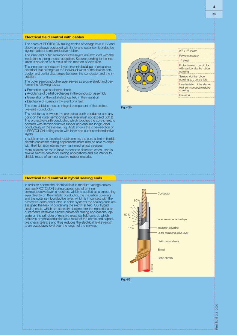
The cores of PROTOLON trailing cables of voltage level 6 kV andabove are always equipped with inner and outer semiconductivelayers made of semiconductive rubber.The inner and outer semiconductive layers are extruded with theinsulation in a single-pass operation. Secure bonding to the insu-lation is obtained as a result of this method of extrusion.The inner semiconductive layer prevents build-up of excessiveelectrical field strength at the individual wires of the flexible con-ductor and partial discharges between the conductor and the in-sulation.The outer semiconductive layer serves as a core shield and per-forms the following tasks:
l Protection against electric shockl Avoidance of partial discharges in the conductor assemblyl Generation of the radial electrical field in the insulationl Discharge of current in the event of a fault.The core shield is thus an integral component of the protec-tive-earth conductor.The resistance between the protective-earth conductor and anypoint on the outer semiconductive layer must not exceed 500 Ω.The protective-earth conductor, which touches the core shield, iscovered with semiconductive rubber and ensures longitudinalconductivity of the system. Fig. 4/20 shows the cross-section ofa PROTOLON trailing cable with inner and outer semiconductivelayers.In addition to the electrical requirements, the core shield in flexibleelectric cables for mining applications must also be able to copewith the high (sometimes very high) mechanical stresses.Metal shields are more liable to become defective when used inflexible electric cables for mining applications and are inferior toshields made of semiconductive rubber material.
Fig. 4/20
2nd + 3rd sheath
Power conductor
1st sheath
Protective-earth conductorwith semiconductive rubbercovering
Semiconductive rubbercovering as a core shield
Inner limitation of the electricfield, semiconductive rubbercovering
Insulation
Electrical field control in hybrid sealing ends
In order to control the electrical field in medium-voltage cablessuch as PROTOLON trailing cables, use of an innersemiconductive layer is required, which is applied as a smoothinglayer directly on the metallic conductor, the insulation coveringand the outer semiconductive layer, which is in contact with theprotective-earth conductor. In cable systems the sealing ends areassigned the task of containing the electrical field. Our hybridsealing ends, which are specially designed for the operational re-quirements of flexible electric cables for mining applications, op-erate on the principle of resistive electrical field control, whichachieves potential reduction as a result of the ohmic and capaci-tive characteristics and thus reduces the electrical field strengthto an acceptable level over the length of the serving.
Conductor
Inner semiconductive layer
Insulation covering
Outer semiconductive layer
Shield
Cable sheath
Field control sleeve
4
36
Fig. 4/21

Pire
lliB
UIS
2.3
·200
0
The basic criteria of the core arrangementfor flexible electric cables for miningapplications are summarized in the adja-cent table.In round flexible electric cables, the individ-ual cores are arranged by laying them up.Up to four cores are laid up without a cen-tral element. Five cores and above are laidup around a centre, which can also consistof three-core stranded elements.A stretched core in the centre of the flexiblecable (as the actual centre or placed in thecentre) is not permitted according to theDIN VDE standards. A stretched core at thecentre of the flexible cable would quickly re-sult in premature failure of the conductordue to breakage, especially in flexible elec-tric cables for mining applications.A maximum of three core layers is best forthe conductor assembly. Investigationshave shown that, if there are more thanthree layers, the internal stability of the flexi-ble cable and in consequence the servicelife is reduced as a result of increasing sec-ondary and relative forces between thecores.The length of lay S is a design feature usedfor laying up the conductor assembly (seetable 4/30) and influences the bending flexi-bility and the bending stability. The length oflay is an important factor for the service lifeof flexible electric cables for mining applica-tions.
Round flexible cables
Laying up of two to four cores without acentre
Laying up of five or more cores with centreSpecial design: the centre comprises threecores
Maximum three-layer design(standard up to 44 cores)
A stretched core in the centre of a flexiblecable is not permitted
The length of lay S is the length, meas-ured in the direction of the lay, over whicha core circumscribes 360° around the lay-ing axis.It is given as a multiple of the diameter Dover the conductor assembly, e.g.S = 8 x D.
Table 4/30
Design Features 4
37
Core arrangement
Centre
Centre
Cores
Stretched core
Cores

Pire
lliB
UIS
2.3
·200
0
Table 4/31 shows the normal lengths of lay in flexible electric cables for mining applications.
Type of cable Length of lay for flexible electric cablesfor mining applications
Flexible cables
5 x D
7 x D
Power cableControl cable
15 x D25 x D
10 x D
10 x D
Especially laid-up around a GFK support element
12 x D
12 x D
10 x D
Laid-up pairsLaid-up cores
≥ 25 x D≥ 15 x D
Table 4/31
Flexible reeling cablesNSHTÖU
Rubber-sheathed flexible cables(N)SHÖU and NSSHÖU
Flexible cablesfor trailing operationNTSCGEWÖU
Trailing cables for dredgerNTSCGEWÖU
Rubber-sheathed flexiblefibre-optic cables
Medium-voltage flexible cablesF-(N)TSCGEWÖU
Medium-voltage flexible cablesNYHSSYCY, N3GHSSYCY
CORDAFLEX (S)
PROTOMONT (M)
PROTOLON (SB)
PROTOLON (ST)
SUPROMONT
OPTOFLEX (M)
R-(N)TSCGEWÖU PROTOLON (M)-R
PROTOLON (M)-F
PROTOLON mine hoist c.Mine hoist cablesNTMTWÖU
PROTOMONT MSR-MiningData, signal and control cables formining installations2YSLGCGÖU
Core arrangement
4
38
Length of lay S
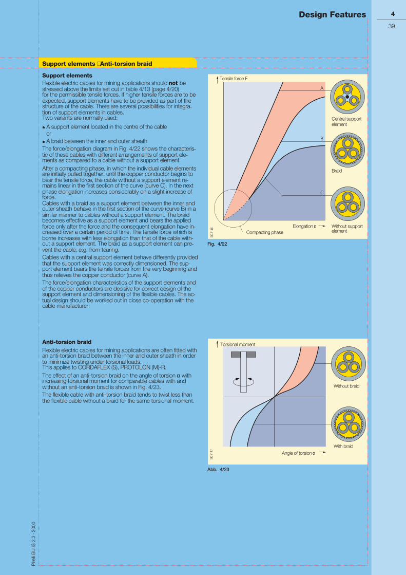
Pire
lliB
UIS
2.3
·200
0
Support elementsFlexible electric cables for mining applications should not bestressed above the limits set out in table 4/13 (page 4/20)for the permissible tensile forces. If higher tensile forces are to beexpected, support elements have to be provided as part of thestructure of the cable. There are several possibilities for integra-tion of support elements in cables.Two variants are normally used:
l A support element located in the centre of the cableor
l A braid between the inner and outer sheathThe force/elongation diagram in Fig. 4/22 shows the characteris-tic of these cables with different arrangements of support ele-ments as compared to a cable without a support element.After a compacting phase, in which the individual cable elementsare initially pulled together, until the copper conductor begins tobear the tensile force, the cable without a support element re-mains linear in the first section of the curve (curve C). In the nextphase elongation increases considerably on a slight increase offorce.Cables with a braid as a support element between the inner andouter sheath behave in the first section of the curve (curve B) in asimilar manner to cables without a support element. The braidbecomes effective as a support element and bears the appliedforce only after the force and the consequent elongation have in-creased over a certain period of time. The tensile force which isborne increases with less elongation than that of the cable with-out a support element. The braid as a support element can pre-vent the cable, e.g. from tearing.Cables with a central support element behave differently providedthat the support element was correctly dimensioned. The sup-port element bears the tensile forces from the very beginning andthus relieves the copper conductor (curve A).The force/elongation characteristics of the support elements andof the copper conductors are decisive for correct design of thesupport element and dimensioning of the flexible cables. The ac-tual design should be worked out in close co-operation with thecable manufacturer.
Anti-torsion braidFlexible electric cables for mining applications are often fitted withan anti-torsion braid between the inner and outer sheath in orderto minimize twisting under torsional loads.This applies to CORDAFLEX (S), PROTOLON (M)-R.The effect of an anti-torsion braid on the angle of torsion α withincreasing torsional moment for comparable cables with andwithout an anti-torsion braid is shown in Fig. 4/23.The flexible cable with anti-torsion braid tends to twist less thanthe flexible cable without a braid for the same torsional moment.
Fig. 4/22
Abb. 4/23
Design Features 4
39
Support elements ⋅ Anti-torsion braid
Tensile force F
Compacting phaseElongation ε
Central supportelement
Braid
Without supportelement
Torsional moment
Angle of torsion α
Without braid
With braid

Pire
lliB
UIS
2.3
·200
0
Pirelli flexible electric cables for mining applica-tions are marked on the outer sheath as shownin table 4/32.In addition, some flexible cables contain com-pany identification threads and/or VDE identifi-cation threads..
Flexible cables Type Marking on outer sheath Companyidentificationthread
VDEidentificationthread
CORDAFLEX (S)NSHTÖU-J/-O (number of cores) x (cross-section)
in the coreassembly
in the coreassembly
(Year of manufacture) OPTOFLEX (M) 6 x (number of fibres) x(core diameter) / 125 Micron
No No
PROTOLON (M) R- or F-(N)TSCGEWÖU (number of cores) x(cross-section) (rated voltage) (year of manufacture)
No No
<VDE> PROTOLON (SB) (number of cores) x (cross-section)(rated voltage) (year of manufacture) (serial number)
No No
<VDE> PROTOLON (ST) NTS.. (number of cores) x (cross-section) (rated voltage) (year of manufacture) (serial number)
No No
<VDE> PROTOMONT or PROTOMONT (Z) orPROTOMONT (V) NSSH.. or NTMTWÖU or NTS...(number of cores) x (cross-section) (year of manufacture)
No No
PROTOMONT (M) (N)SHÖU (number of cores) x(cross-section) (voltage) (year of manufacture)
No No
<VDE> SUPROMONT N .. HSSYCY(cross-section) (year of manufacture)
No No
PROTOMONT MSR-Mining 2YSLGCGÖU No No
Table 4/32
CORDAFLEX(S)
OPTOFLEX (M)
PROTOLON (M)
PROTOLON (SB)
PROTOLON (ST)
PROTOMONT
PROTOMONT (M)
SUPROMONT
NSHTÖU
R-(N)TSCGEWÖUF-(N)TSCGEWÖU
NTSCGEWÖU
(N)SHÖU
Marking
4
40
NTSCGEWÖU
N.. HSSYCY
PROTOMONT MSR-Mining 2YSLGCGÖU
Design Features
NSSH ...ÖUNTMTWÖUNTSCGECWÖU

Pire
lliB
UIS
2.3
·200
0
4
41
4
41

Catalog index
4
42
Pire
lliB
UIS
2.3
·200
0
Catalog title Designation Order No.
SIENOPYR® Power Cables SK 3.30 E50001-K8133-A101-A1-7600
Installation Cables, Power Cables SK 3.40 E50001-K8134-A101-A2-7600
Cables for Industrial Applications
Flexible Electric Cables for Cranes and Material Handling Equipment BU IS 2.1 E50001-K8112-A101-A2-7600
Flexible Electric Cables for Mining Applications BU IS 2.3 E50001-K8113-A101-A1-7600
Special Purpose Cables for Industrial Applications SK 4.20 E50001-K8142-A101-A1-7600
Application and Export Back Office Berlin Cable Repair Department
BU IS ATAustraße 99D-96465 Neustadt near CoburgGermanyTel: (+49) 9568 93 2376Fax: (+49) 9568 93 2058
BU IS VAGartenfelder Straße 28D-13599 BerlinGermanyTel: (+49) 30 386 30126Fax: (+49) 30 386 30140
BU IS ATAustraße 99D-96465 Neustadt near CoburgGermanyTel: (+49) 9568 93 2587Fax: (+49) 9568 93 2016
E Mail [email protected]
Your partners and support for special cables
Order No.: E50001-K8113-A101-A1-7600Printed in GermanyKGK 0800 3.0 144 En 101623 6101/D6089

Kabel und Systeme GmbH und Co.KGAnwendungstechnik und ExportAustraße 99D-96465 Neustadt bei Coburg
Order No.: E50001-K8113-A101-A1-7600