Embed Size (px)
Citation preview

DIAGNOSTIC MANUAL I
TABLE OF CONTENTSForeword.. . . . . . . . . . . . . . . . . . . . . . . . . . . . . . . . . . . . . . . . . . . . . . . . . . . . . . . . . . . . . . . . . . . . . . . . . . . . . . . . . . . . . . . . . . . . . . . . . . . . . . . . . . . . . . . . . .1
Service Diagnosis. . . . . . . . . . . . . . . . . . . . . . . . . . . . . . . . . . . . . . . . . . . . . . . . . . . . . . . . . . . . . . . . . . . . . . . . . . . . . . . . . . . . . . . . . . . . . . . . . . . . . . . .2
Safety Information.. . . . . . . . . . . . . . . . . . . . . . . . . . . . . . . . . . . . . . . . . . . . . . . . . . . . . . . . . . . . . . . . . . . . . . . . . . . . . . . . . . . . . . . . . . . . . . . . . . . . . . .3
SCR Component Locator Guide.. . . . . . . . . . . . . . . . . . . . . . . . . . . . . . . . . . . . . . . . . . . . . . . . . . . . . . . . . . . . . . . . . . . . . . . . . . . . . . . . . . . . . . .7
Engine Systems.. . . . . . . . . . . . . . . . . . . . . . . . . . . . . . . . . . . . . . . . . . . . . . . . . . . . . . . . . . . . . . . . . . . . . . . . . . . . . . . . . . . . . . . . . . . . . . . . . . . . . . . .13
Engine and Vehicle Features.. . . . . . . . . . . . . . . . . . . . . . . . . . . . . . . . . . . . . . . . . . . . . . . . . . . . . . . . . . . . . . . . . . . . . . . . . . . . . . . . . . . . . . . . .75
Diagnostic Software Operation and Special Test Procedures.. . . . . . . . . . . . . . . . . . . . . . . . . . . . . . . . . . . . . . . . . . . . . . . . . .87
Engine Symptoms Diagnostics.. . . . . . . . . . . . . . . . . . . . . . . . . . . . . . . . . . . . . . . . . . . . . . . . . . . . . . . . . . . . . . . . . . . . . . . . . . . . . . . . . . . . .125
Engine System Tests and Inspections.. . . . . . . . . . . . . . . . . . . . . . . . . . . . . . . . . . . . . . . . . . . . . . . . . . . . . . . . . . . . . . . . . . . . . . . . . . . .185
Electronic Control Systems Diagnostics. . . . . . . . . . . . . . . . . . . . . . . . . . . . . . . . . . . . . . . . . . . . . . . . . . . . . . . . . . . . . . . . . . . . . . . . . .247
Diagnostic Tools and Accessories. . . . . . . . . . . . . . . . . . . . . . . . . . . . . . . . . . . . . . . . . . . . . . . . . . . . . . . . . . . . . . . . . . . . . . . . . . . . . . . .1455
Abbreviations and Acronyms.. . . . . . . . . . . . . . . . . . . . . . . . . . . . . . . . . . . . . . . . . . . . . . . . . . . . . . . . . . . . . . . . . . . . . . . . . . . . . . . . . . . . .1507
Terminology.. . . . . . . . . . . . . . . . . . . . . . . . . . . . . . . . . . . . . . . . . . . . . . . . . . . . . . . . . . . . . . . . . . . . . . . . . . . . . . . . . . . . . . . . . . . . . . . . . . . . . . . . . .1519
Appendix A: Performance Specifications.. . . . . . . . . . . . . . . . . . . . . . . . . . . . . . . . . . . . . . . . . . . . . . . . . . . . . . . . . . . . . . . . . . . . . . .1533
Appendix B: Signal Values.. . . . . . . . . . . . . . . . . . . . . . . . . . . . . . . . . . . . . . . . . . . . . . . . . . . . . . . . . . . . . . . . . . . . . . . . . . . . . . . . . . . . . . . . .1547
Appendix C: Technical Service Information (TSI). . . . . . . . . . . . . . . . . . . . . . . . . . . . . . . . . . . . . . . . . . . . . . . . . . . . . . . . . . . . . . .1561
Appendix D: Component Locator. . . . . . . . . . . . . . . . . . . . . . . . . . . . . . . . . . . . . . . . . . . . . . . . . . . . . . . . . . . . . . . . . . . . . . . . . . . . . . . . .1565

II DIAGNOSTIC MANUAL

DIAGNOSTIC MANUAL 1
ForewordNavistar, Inc. is committed to continuous research and development to improve products and introducetechnological advances. Procedures, specifications, and parts defined in published technical service literaturemay be altered.
NOTE: Photo illustrations identify specific parts or assemblies that support text and procedures; other areas ina photo illustration may not be exact.
This manual includes necessary information and specifications for technicians to maintain Navistar® dieselengines. See vehicle manuals and Technical Service Information (TSI) bulletins for additional information.
Technical Service LiteratureNavistar® N13 with SCR Engine Operation and Maintenance Manual
Navistar® N13 with SCR Engine Service Manual
Navistar® N13 with SCR Engine and Aftertreatment Wiring Schematic Form
Technical Service Literature is revised periodically. If a technical publication is ordered, the latest revision willbe supplied.
NOTE: To order technical service literature, contact your International dealer.

2 DIAGNOSTIC MANUAL
Service DiagnosisService diagnosis is an investigative procedure that must be followed to find and correct an engine applicationproblem or an engine problem.
If the problem is engine application, see specific vehicle manuals for further diagnostic information.
If the problem is the engine, see specific Engine Diagnostic Manual for further diagnostic information.
Prerequisites for Effective Diagnosis
• Availability of gauges and diagnostic test equipment
• Availability of current information for engine application and engine systems
• Knowledge of the principles of operation for engine application and engine systems
• Knowledge to understand and do procedures in diagnostic and service publications
Technical Service Literature required for Effective Diagnosis
• Engine Service Manual
• Engine Diagnostic Manual
• Diagnostics Forms
• Engine Wiring Schematic Form
• Service Bulletins
DIAGNOSTIC MANUAL 3
Safety InformationThis manual provides general and specific maintenance procedures essential for reliable engine operation andyour safety. Since many variations in procedures, tools, and service parts are involved, advice for all possiblesafety conditions and hazards cannot be stated.
Read safety instructions before doing any service and test procedures for the engine or vehicle. See relatedapplication manuals for more information.
Disregard for Safety Instructions, Warnings, Cautions, and Notes in this manual can lead to injury, death ordamage to the engine or vehicle.
Safety Terminology
Three terms are used to stress your safety and safe operation of the engine: Warning, Caution, and Note
Warning: A warning describes actions necessary to prevent or eliminate conditions, hazards, and unsafepractices that can cause personal injury or death.
Caution: A caution describes actions necessary to prevent or eliminate conditions that can cause damage tothe engine or vehicle.
Note: A note describes actions necessary for correct, efficient engine operation.
Safety Instructions
Work Area
• Keep work area clean, dry, and organized.
• Keep tools and parts off the floor.
• Make sure the work area is ventilated and well lit.
• Make sure a First Aid Kit is available.
Safety Equipment
• Use correct lifting devices.
• Use safety blocks and stands.
Protective Measures
• Wear protective safety glasses and shoes.
• Wear correct hearing protection.
• Wear cotton work clothing.
• Wear sleeved heat protective gloves.
• Do not wear rings, watches or other jewelry.
• Restrain long hair.
Vehicle
• Make sure the vehicle is in neutral, the parking brake is set, and the wheels are blocked before servicingengine.
4 DIAGNOSTIC MANUAL
• Clear the area before starting the engine.
Engine
• The engine should be operated or serviced only by qualified individuals.
• Provide necessary ventilation when operating engine in a closed area.
• Keep combustible material away from engine exhaust system and exhaust manifolds.
• Install all shields, guards, and access covers before operating engine.
• Do not run engine with unprotected air inlets or exhaust openings. If unavoidable for service reasons, putprotective screens over all openings before servicing engine.
• Shut engine off and relieve all pressure in the system before removing panels, housing covers, and caps.
• If an engine is not safe to operate, tag the engine and ignition key.
Fire Prevention
• Make sure charged fire extinguishers are in the work area.
NOTE: Check the classification of each fire extinguisher to ensure that the following fire types can beextinguished.
1. Type A — Wood, paper, textiles, and rubbish
2. Type B — Flammable liquids
3. Type C — Electrical equipment
Batteries
• Always disconnect the main negative battery cable first.
• Always connect the main negative battery cable last.
• Avoid leaning over batteries.
• Protect your eyes.
• Do not expose batteries to open flames or sparks.
• Do not smoke in workplace.
Compressed Air
• Use an OSHA approved blow gun rated at 30 psi.(207 kPa)
• Limit shop air pressure to 30 psi (207 kPa).
• Wear safety glasses or goggles.
• Wear hearing protection.
• Use shielding to protect others in the work area.
• Do not direct compressed air at body or clothing.
Tools
• Make sure all tools are in good condition.
• Make sure all standard electrical tools are grounded.
DIAGNOSTIC MANUAL 5
• Check for frayed power cords before using power tools.
Fluids Under Pressure
• Use extreme caution when working on systems under pressure.
• Follow approved procedures only.
Fuel
• Do not over fill the fuel tank. Over fill creates a fire hazard.
• Do not smoke in the work area.
• Do not refuel the tank when the engine is running.
Removal of Tools, Parts, and Equipment
• Reinstall all safety guards, shields, and covers after servicing the engine.
• Make sure all tools, parts, and service equipment are removed from the engine and vehicle after all work isdone.

6 DIAGNOSTIC MANUAL

1 SCR COMPONENT LOCATOR GUIDE 7
Table of Contents
SCR Component Locator. . . . . . . . . . . . . . . . . . . . . . . . . . . . . . . . . . . . . . . . . . . . . . . . . . . . . . . . . . . . . . . . . . . . . . . . . . . . . . . . . . . . . . . . . . . . . . . .9

8 1 SCR COMPONENT LOCATOR GUIDE

1 SCR COMPONENT LOCATOR GUIDE 9
SCR Component LocatorSCR Switchback Assembly
Figure 1 SCR Switchback Assembly
1. Exhaust Jumper Harness2. Decomposition Reactor Tube
3. Selective Catalyst Reduction(SCR) assembly
4. Diesel Particular Filter (DPF)assembly
10 1 SCR COMPONENT LOCATOR GUIDE
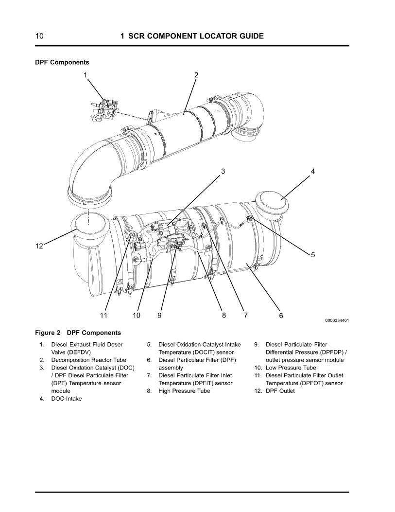
DPF Components
Figure 2 DPF Components
1. Diesel Exhaust Fluid DoserValve (DEFDV)
2. Decomposition Reactor Tube3. Diesel Oxidation Catalyst (DOC)
/ DPF Diesel Particulate Filter(DPF) Temperature sensormodule
4. DOC Intake
5. Diesel Oxidation Catalyst IntakeTemperature (DOCIT) sensor
6. Diesel Particulate Filter (DPF)assembly
7. Diesel Particulate Filter InletTemperature (DPFIT) sensor
8. High Pressure Tube
9. Diesel Particulate FilterDifferential Pressure (DPFDP) /outlet pressure sensor module
10. Low Pressure Tube11. Diesel Particulate Filter Outlet
Temperature (DPFOT) sensor12. DPF Outlet

1 SCR COMPONENT LOCATOR GUIDE 11
SCR Components
Figure 3 SCR Components
1. NOx Out sensor2. Selective Catalyst Reduction
Outlet Temperature (SCROT)sensor
3. NOx Sensor Module
4. Selective Catalyst ReductionInlet Temperature (SCRIT)sensor
5. Selective Catalyst Reduction(SCR) temperature sensormodule
6. Ammonia (NH3) sensor module7. Ammonia (NH3) sensor8. SCR sensor jumper harness9. Selective Catalyst Reduction
(SCR) assembly

12 1 SCR COMPONENT LOCATOR GUIDE
2 ENGINE SYSTEMS 13
Table of Contents
Engine Identification.. . . . . . . . . . . . . . . . . . . . . . . . . . . . . . . . . . . . . . . . . . . . . . . . . . . . . . . . . . . . . . . . . . . . . . . . . . . . . . . . . . . . . . . . . . . . . . . . . . .17Engine Serial Number. . . . . . . . . . . . . . . . . . . . . . . . . . . . . . . . . . . . . . . . . . . . . . . . . . . . . . . . . . . . . . . . . . . . . . . . . . . . . . . . . . . . . . . . .17Engine Emission Label . . . . . . . . . . . . . . . . . . . . . . . . . . . . . . . . . . . . . . . . . . . . . . . . . . . . . . . . . . . . . . . . . . . . . . . . . . . . . . . . . . . . . . .18Engine Accessory Labels and Identification Plates. . . . . . . . . . . . . . . . . . . . . . . . . . . . . . . . . . . . . . . . . . . . . . . . . . . . .19Engine Specifications.. . . . . . . . . . . . . . . . . . . . . . . . . . . . . . . . . . . . . . . . . . . . . . . . . . . . . . . . . . . . . . . . . . . . . . . . . . . . . . . . . . . . . . . .19
Heavy Duty On Board Diagnostics (HD-OBD). . . . . . . . . . . . . . . . . . . . . . . . . . . . . . . . . . . . . . . . . . . . . . . . . . .21Engine Description.. . . . . . . . . . . . . . . . . . . . . . . . . . . . . . . . . . . . . . . . . . . . . . . . . . . . . . . . . . . . . . . . . . . . . . . . . . . . . . . . . .21Optional Equipment. . . . . . . . . . . . . . . . . . . . . . . . . . . . . . . . . . . . . . . . . . . . . . . . . . . . . . . . . . . . . . . . . . . . . . . . . . . . . . . . . .22Chassis Mounted Equipment. . . . . . . . . . . . . . . . . . . . . . . . . . . . . . . . . . . . . . . . . . . . . . . . . . . . . . . . . . . . . . . . . . . . . .22
Air Management System.. . . . . . . . . . . . . . . . . . . . . . . . . . . . . . . . . . . . . . . . . . . . . . . . . . . . . . . . . . . . . . . . . . . . . . . . . . . . . . . . . . . . . . . . . . . . . .24Airflow .. . . . . . . . . . . . . . . . . . . . . . . . . . . . . . . . . . . . . . . . . . . . . . . . . . . . . . . . . . . . . . . . . . . . . . . . . . . . . . . . . . . . . . . . . . . . . . . . . . . . . . . . . .25Turbochargers.. . . . . . . . . . . . . . . . . . . . . . . . . . . . . . . . . . . . . . . . . . . . . . . . . . . . . . . . . . . . . . . . . . . . . . . . . . . . . . . . . . . . . . . . . . . . . . . . .26Air Control Valve (ACV). . . . . . . . . . . . . . . . . . . . . . . . . . . . . . . . . . . . . . . . . . . . . . . . . . . . . . . . . . . . . . . . . . . . . . . . . . . . . . . . . . . . . . .27Boost Control. . . . . . . . . . . . . . . . . . . . . . . . . . . . . . . . . . . . . . . . . . . . . . . . . . . . . . . . . . . . . . . . . . . . . . . . . . . . . . . . . . . . . . . . . . . . . . . . . . .28Low Pressure Charge Air Cooler (LPCAC). . . . . . . . . . . . . . . . . . . . . . . . . . . . . . . . . . . . . . . . . . . . . . . . . . . . . . . . . . . . . . . .28High Pressure Charge Air Cooler (HPCAC). . . . . . . . . . . . . . . . . . . . . . . . . . . . . . . . . . . . . . . . . . . . . . . . . . . . . . . . . . . . . . .28Intake Manifold Pressure (IMP) Sensor . . . . . . . . . . . . . . . . . . . . . . . . . . . . . . . . . . . . . . . . . . . . . . . . . . . . . . . . . . . . . . . . . . .28Intake Manifold Temperature (IMT) Sensor . . . . . . . . . . . . . . . . . . . . . . . . . . . . . . . . . . . . . . . . . . . . . . . . . . . . . . . . . . . . . . .28Turbocharger 2 Compressor Inlet Sensor (TC2IS) . . . . . . . . . . . . . . . . . . . . . . . . . . . . . . . . . . . . . . . . . . . . . . . . . . . . . .29Exhaust Gas Recirculation (EGR) System.. . . . . . . . . . . . . . . . . . . . . . . . . . . . . . . . . . . . . . . . . . . . . . . . . . . . . . . . . . . . . . .30Aftertreatment (AFT) System.. . . . . . . . . . . . . . . . . . . . . . . . . . . . . . . . . . . . . . . . . . . . . . . . . . . . . . . . . . . . . . . . . . . . . . . . . . . . . . .34
Decomposition Reactor Tube.. . . . . . . . . . . . . . . . . . . . . . . . . . . . . . . . . . . . . . . . . . . . . . . . . . . . . . . . . . . . . . . . . . . . .36Diesel Particulate Filter (DPF). . . . . . . . . . . . . . . . . . . . . . . . . . . . . . . . . . . . . . . . . . . . . . . . . . . . . . . . . . . . . . . . . . . . . .36Diesel Oxidation Catalyst (DOC).. . . . . . . . . . . . . . . . . . . . . . . . . . . . . . . . . . . . . . . . . . . . . . . . . . . . . . . . . . . . . . . . . .36Selective Catalyst Reduction (SCR) Catalyst. . . . . . . . . . . . . . . . . . . . . . . . . . . . . . . . . . . . . . . . . . . . . . . . . . .36Aftertreatment (AFT) System Conditions and Responses.. . . . . . . . . . . . . . . . . . . . . . . . . . . . . . . . . . .36Diesel Exhaust Fluid (DEF) Injection. . . . . . . . . . . . . . . . . . . . . . . . . . . . . . . . . . . . . . . . . . . . . . . . . . . . . . . . . . . . .37Aftertreatment Fuel Injection.. . . . . . . . . . . . . . . . . . . . . . . . . . . . . . . . . . . . . . . . . . . . . . . . . . . . . . . . . . . . . . . . . . . . . .38
Crankcase Oil Separator. . . . . . . . . . . . . . . . . . . . . . . . . . . . . . . . . . . . . . . . . . . . . . . . . . . . . . . . . . . . . . . . . . . . . . . . . . . . . . . . . . . . . .40
Fuel Management System.. . . . . . . . . . . . . . . . . . . . . . . . . . . . . . . . . . . . . . . . . . . . . . . . . . . . . . . . . . . . . . . . . . . . . . . . . . . . . . . . . . . . . . . . . . . .42Fuel System Components. . . . . . . . . . . . . . . . . . . . . . . . . . . . . . . . . . . . . . . . . . . . . . . . . . . . . . . . . . . . . . . . . . . . . . . . . . . . . . . . . . . .42Fuel Flow.. . . . . . . . . . . . . . . . . . . . . . . . . . . . . . . . . . . . . . . . . . . . . . . . . . . . . . . . . . . . . . . . . . . . . . . . . . . . . . . . . . . . . . . . . . . . . . . . . . . . . . .43Low Pressure Fuel System.. . . . . . . . . . . . . . . . . . . . . . . . . . . . . . . . . . . . . . . . . . . . . . . . . . . . . . . . . . . . . . . . . . . . . . . . . . . . . . . . . .44High Pressure Fuel System.. . . . . . . . . . . . . . . . . . . . . . . . . . . . . . . . . . . . . . . . . . . . . . . . . . . . . . . . . . . . . . . . . . . . . . . . . . . . . . . . .46
Inlet Air Heater System.. . . . . . . . . . . . . . . . . . . . . . . . . . . . . . . . . . . . . . . . . . . . . . . . . . . . . . . . . . . . . . . . . . . . . . . . . . . . . . . . . . . . . . . . . . . . . . . .48Inlet Air Heater System Components. . . . . . . . . . . . . . . . . . . . . . . . . . . . . . . . . . . . . . . . . . . . . . . . . . . . . . . . . . . . . . . . . . . . . .48Inlet Air Heater System Operation.. . . . . . . . . . . . . . . . . . . . . . . . . . . . . . . . . . . . . . . . . . . . . . . . . . . . . . . . . . . . . . . . . . . . . . . . .49
Oil Flow System.. . . . . . . . . . . . . . . . . . . . . . . . . . . . . . . . . . . . . . . . . . . . . . . . . . . . . . . . . . . . . . . . . . . . . . . . . . . . . . . . . . . . . . . . . . . . . . . . . . . . . . . .51Oil Flow and Components. . . . . . . . . . . . . . . . . . . . . . . . . . . . . . . . . . . . . . . . . . . . . . . . . . . . . . . . . . . . . . . . . . . . . . . . . . . . . . . . . . . .51Crankcase Oil Separator. . . . . . . . . . . . . . . . . . . . . . . . . . . . . . . . . . . . . . . . . . . . . . . . . . . . . . . . . . . . . . . . . . . . . . . . . . . . . . . . . . . . . .53Remote Mounted Centrifugal Oil Filter (Optional). . . . . . . . . . . . . . . . . . . . . . . . . . . . . . . . . . . . . . . . . . . . . . . . . . . . . . .53
14 2 ENGINE SYSTEMS
Engine Cooling System.. . . . . . . . . . . . . . . . . . . . . . . . . . . . . . . . . . . . . . . . . . . . . . . . . . . . . . . . . . . . . . . . . . . . . . . . . . . . . . . . . . . . . . . . . . . . . . .55Cooling System Flow.. . . . . . . . . . . . . . . . . . . . . . . . . . . . . . . . . . . . . . . . . . . . . . . . . . . . . . . . . . . . . . . . . . . . . . . . . . . . . . . . . . . . . . . . .55Thermostat Operation.. . . . . . . . . . . . . . . . . . . . . . . . . . . . . . . . . . . . . . . . . . . . . . . . . . . . . . . . . . . . . . . . . . . . . . . . . . . . . . . . . . . . . . . .57Coolant Control Valve (CCV) assembly operation. . . . . . . . . . . . . . . . . . . . . . . . . . . . . . . . . . . . . . . . . . . . . . . . . . . . . . .57
Engine Brake System.. . . . . . . . . . . . . . . . . . . . . . . . . . . . . . . . . . . . . . . . . . . . . . . . . . . . . . . . . . . . . . . . . . . . . . . . . . . . . . . . . . . . . . . . . . . . . . . . . .58Engine Brake Control System Components. . . . . . . . . . . . . . . . . . . . . . . . . . . . . . . . . . . . . . . . . . . . . . . . . . . . . . . . . . . . . .58Engine Brake System Description.. . . . . . . . . . . . . . . . . . . . . . . . . . . . . . . . . . . . . . . . . . . . . . . . . . . . . . . . . . . . . . . . . . . . . . . . .59Engine Brake System Operation.. . . . . . . . . . . . . . . . . . . . . . . . . . . . . . . . . . . . . . . . . . . . . . . . . . . . . . . . . . . . . . . . . . . . . . . . . . .59
Electronic Control System.. . . . . . . . . . . . . . . . . . . . . . . . . . . . . . . . . . . . . . . . . . . . . . . . . . . . . . . . . . . . . . . . . . . . . . . . . . . . . . . . . . . . . . . . . . . .60Electronic Control System Components. . . . . . . . . . . . . . . . . . . . . . . . . . . . . . . . . . . . . . . . . . . . . . . . . . . . . . . . . . . . . . . . . .60
Operation and Function.. . . . . . . . . . . . . . . . . . . . . . . . . . . . . . . . . . . . . . . . . . . . . . . . . . . . . . . . . . . . . . . . . . . . . . . . . . . .60Reference Voltage (VREF). . . . . . . . . . . . . . . . . . . . . . . . . . . . . . . . . . . . . . . . . . . . . . . . . . . . . . . . . . . . . . . . . . . . . . . . . .60Signal Conditioner. . . . . . . . . . . . . . . . . . . . . . . . . . . . . . . . . . . . . . . . . . . . . . . . . . . . . . . . . . . . . . . . . . . . . . . . . . . . . . . . . . .60Microprocessor. . . . . . . . . . . . . . . . . . . . . . . . . . . . . . . . . . . . . . . . . . . . . . . . . . . . . . . . . . . . . . . . . . . . . . . . . . . . . . . . . . . . . . .60Diagnostic Trouble Codes.. . . . . . . . . . . . . . . . . . . . . . . . . . . . . . . . . . . . . . . . . . . . . . . . . . . . . . . . . . . . . . . . . . . . . . . . .60Microprocessor Memory.. . . . . . . . . . . . . . . . . . . . . . . . . . . . . . . . . . . . . . . . . . . . . . . . . . . . . . . . . . . . . . . . . . . . . . . . . . .60Actuator Control. . . . . . . . . . . . . . . . . . . . . . . . . . . . . . . . . . . . . . . . . . . . . . . . . . . . . . . . . . . . . . . . . . . . . . . . . . . . . . . . . . . . . .62
Actuators. . . . . . . . . . . . . . . . . . . . . . . . . . . . . . . . . . . . . . . . . . . . . . . . . . . . . . . . . . . . . . . . . . . . . . . . . . . . . . . . . . . . . . . . . . . . . . . . . . . . . . . .62Coolant Control Valve (CCV). . . . . . . . . . . . . . . . . . . . . . . . . . . . . . . . . . . . . . . . . . . . . . . . . . . . . . . . . . . . . . . . . . . . . . .63Exhaust Back Pressure Valve (EBPV) Control. . . . . . . . . . . . . . . . . . . . . . . . . . . . . . . . . . . . . . . . . . . . . . . . . .63Exhaust Gas Recirculation (EGR) Valve . . . . . . . . . . . . . . . . . . . . . . . . . . . . . . . . . . . . . . . . . . . . . . . . . . . . . . . . .63Air Control Valve (ACV). . . . . . . . . . . . . . . . . . . . . . . . . . . . . . . . . . . . . . . . . . . . . . . . . . . . . . . . . . . . . . . . . . . . . . . . . . . . .63Inlet Air Heater Relay (IAHR). . . . . . . . . . . . . . . . . . . . . . . . . . . . . . . . . . . . . . . . . . . . . . . . . . . . . . . . . . . . . . . . . . . . . . .63Inlet Air Heater Fuel Solenoid (IAHFS) Valve. . . . . . . . . . . . . . . . . . . . . . . . . . . . . . . . . . . . . . . . . . . . . . . . . . . .63Engine Throttle Valve (ETV). . . . . . . . . . . . . . . . . . . . . . . . . . . . . . . . . . . . . . . . . . . . . . . . . . . . . . . . . . . . . . . . . . . . . . . .64Fuel Pressure Control Valve (FPCV). . . . . . . . . . . . . . . . . . . . . . . . . . . . . . . . . . . . . . . . . . . . . . . . . . . . . . . . . . . . . .64Aftertreatment Fuel Shutoff Valve (AFTFSV). . . . . . . . . . . . . . . . . . . . . . . . . . . . . . . . . . . . . . . . . . . . . . . . . . . .64Aftertreatment Purge Air Valve (AFTPAV). . . . . . . . . . . . . . . . . . . . . . . . . . . . . . . . . . . . . . . . . . . . . . . . . . . . . . . .64Diesel Exhaust Fluid Dosing Unit Heater (DEFDUH). . . . . . . . . . . . . . . . . . . . . . . . . . . . . . . . . . . . . . . . . . .64Diesel Exhaust Fluid Doser Valve (DEFDV). . . . . . . . . . . . . . . . . . . . . . . . . . . . . . . . . . . . . . . . . . . . . . . . . . . . . .64Diesel Exhaust Fluid Line Heater Relay (DEFLHR). . . . . . . . . . . . . . . . . . . . . . . . . . . . . . . . . . . . . . . . . . . . .64Diesel Exhaust Fluid Pressure Line Heater (DEFPLH). . . . . . . . . . . . . . . . . . . . . . . . . . . . . . . . . . . . . . . . .65Diesel Exhaust Fluid Return Line Heater (DEFRLH). . . . . . . . . . . . . . . . . . . . . . . . . . . . . . . . . . . . . . . . . . .65Diesel Exhaust Fluid Return Valve (DEFRV). . . . . . . . . . . . . . . . . . . . . . . . . . . . . . . . . . . . . . . . . . . . . . . . . . . . .65Diesel Exhaust Fluid Suction Line Heater (DEFSLH). . . . . . . . . . . . . . . . . . . . . . . . . . . . . . . . . . . . . . . . . .65Diesel Exhaust Fluid Supply Pump (DEFSP) and Temperature Sensor. . . . . . . . . . . . . . . . . . . .65Diesel Exhaust Fluid Tank Heater Valve (DEFTHC). . . . . . . . . . . . . . . . . . . . . . . . . . . . . . . . . . . . . . . . . . . .65Diesel Exhaust Fluid Unit Heater Relay (DEFUHR). . . . . . . . . . . . . . . . . . . . . . . . . . . . . . . . . . . . . . . . . . . . .65
Engine and Vehicle Sensors. . . . . . . . . . . . . . . . . . . . . . . . . . . . . . . . . . . . . . . . . . . . . . . . . . . . . . . . . . . . . . . . . . . . . . . . . . . . . . . . .66Thermistor Sensors.. . . . . . . . . . . . . . . . . . . . . . . . . . . . . . . . . . . . . . . . . . . . . . . . . . . . . . . . . . . . . . . . . . . . . . . . . . . . . . . . .66Variable Capacitance Sensors. . . . . . . . . . . . . . . . . . . . . . . . . . . . . . . . . . . . . . . . . . . . . . . . . . . . . . . . . . . . . . . . . . . . .68Magnetic Pickup Sensors.. . . . . . . . . . . . . . . . . . . . . . . . . . . . . . . . . . . . . . . . . . . . . . . . . . . . . . . . . . . . . . . . . . . . . . . . . .71Potentiometer Sensors.. . . . . . . . . . . . . . . . . . . . . . . . . . . . . . . . . . . . . . . . . . . . . . . . . . . . . . . . . . . . . . . . . . . . . . . . . . . . .72Switches.. . . . . . . . . . . . . . . . . . . . . . . . . . . . . . . . . . . . . . . . . . . . . . . . . . . . . . . . . . . . . . . . . . . . . . . . . . . . . . . . . . . . . . . . . . . . . .73
Additional Sensors. . . . . . . . . . . . . . . . . . . . . . . . . . . . . . . . . . . . . . . . . . . . . . . . . . . . . . . . . . . . . . . . . . . . . . . . . . . . . . . . . . . . . . . . . . . .74Ammonia (NH3) Sensor Module. . . . . . . . . . . . . . . . . . . . . . . . . . . . . . . . . . . . . . . . . . . . . . . . . . . . . . . . . . . . . . . . . . . .74Humidity Sensor (HS). . . . . . . . . . . . . . . . . . . . . . . . . . . . . . . . . . . . . . . . . . . . . . . . . . . . . . . . . . . . . . . . . . . . . . . . . . . . . . . .74Nitrogen Oxides (NOx) IN Sensor Module. . . . . . . . . . . . . . . . . . . . . . . . . . . . . . . . . . . . . . . . . . . . . . . . . . . . . . .74Nitrogen Oxides (NOx) OUT Sensor Module. . . . . . . . . . . . . . . . . . . . . . . . . . . . . . . . . . . . . . . . . . . . . . . . . . . .74

2 ENGINE SYSTEMS 15
Oxygen Sensor (O2S). . . . . . . . . . . . . . . . . . . . . . . . . . . . . . . . . . . . . . . . . . . . . . . . . . . . . . . . . . . . . . . . . . . . . . . . . . . . . . . .74

16 2 ENGINE SYSTEMS
2 ENGINE SYSTEMS 17
Engine IdentificationEngine Serial Number
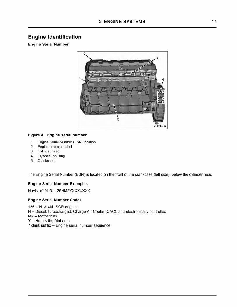
Figure 4 Engine serial number
1. Engine Serial Number (ESN) location2. Engine emission label3. Cylinder head4. Flywheel housing5. Crankcase
The Engine Serial Number (ESN) is located on the front of the crankcase (left side), below the cylinder head.
Engine Serial Number Examples
Navistar® N13: 126HM2YXXXXXXX
Engine Serial Number Codes
126 – N13 with SCR enginesH – Diesel, turbocharged, Charge Air Cooler (CAC), and electronically controlledM2 – Motor truckY – Huntsville, Alabama7 digit suffix – Engine serial number sequence

18 2 ENGINE SYSTEMS
Engine Emission Label
Figure 5 2010 U.S. Environmental Protection Agency (EPA) exhaust emission label (example)
The U.S. Environmental Protection Agency (EPA) exhaust emission label is on top of the valve cover (front leftside). The EPA label typically includes the following:
• Model year
• Engine family, model, and displacement
• Advertised brake horsepower and torque rating
• Emission family and control systems
• Valve lash specifications
• Engine Serial Number (ESN)
• EPA, Onboard Diagnostics (OBD), EURO, and reserved fields for specific applications
2 ENGINE SYSTEMS 19
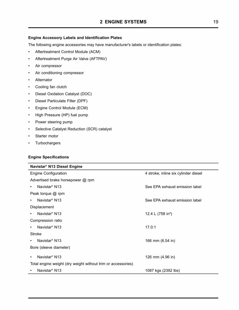
Engine Accessory Labels and Identification Plates
The following engine accessories may have manufacturer's labels or identification plates:
• Aftertreatment Control Module (ACM)
• Aftertreatment Purge Air Valve (AFTPAV)
• Air compressor
• Air conditioning compressor
• Alternator
• Cooling fan clutch
• Diesel Oxidation Catalyst (DOC)
• Diesel Particulate Filter (DPF)
• Engine Control Module (ECM)
• High Pressure (HP) fuel pump
• Power steering pump
• Selective Catalyst Reduction (SCR) catalyst
• Starter motor
• Turbochargers
Engine Specifications
Navistar® N13 Diesel EngineEngine Configuration 4 stroke, inline six cylinder diesel
Advertised brake horsepower @ rpm
• Navistar® N13 See EPA exhaust emission label
Peak torque @ rpm
• Navistar® N13 See EPA exhaust emission label
Displacement
• Navistar® N13 12.4 L (758 in³)
Compression ratio
• Navistar® N13 17.0:1
Stroke
• Navistar® N13 166 mm (6.54 in)
Bore (sleeve diameter)
• Navistar® N13 126 mm (4.96 in)
Total engine weight (dry weight without trim or accessories)
• Navistar® N13 1087 kgs (2392 lbs)

20 2 ENGINE SYSTEMS
Firing order 1-5-3-6-2-4
Engine rotation direction (facing flywheel) Counterclockwise
Aspiration Dual turbocharged and charge air cooled
Combustion system Direct injection turbocharged
Fuel system High-pressure common rail
Lube system capacity (including filter) 40 L (42 qts)
• Navistar® N13
Lube system capacity (overhaul only, with filter) 44 L (46 qts)
• Navistar® N13
Engine oil pressure at operating temperature with SAE 15W-40 oil
• Low idle
• High idle
69 kPa (10 psi) min.
276 - 483 kPa (40 - 70 psi)
Idle speed (no load) 600 rpm, nominal
Thermostat operating temperature
• Primary
• Secondary
83°C - 95°C (181°F - 203°F)
87°C - 102°C (189°F - 216°F)
2 ENGINE SYSTEMS 21
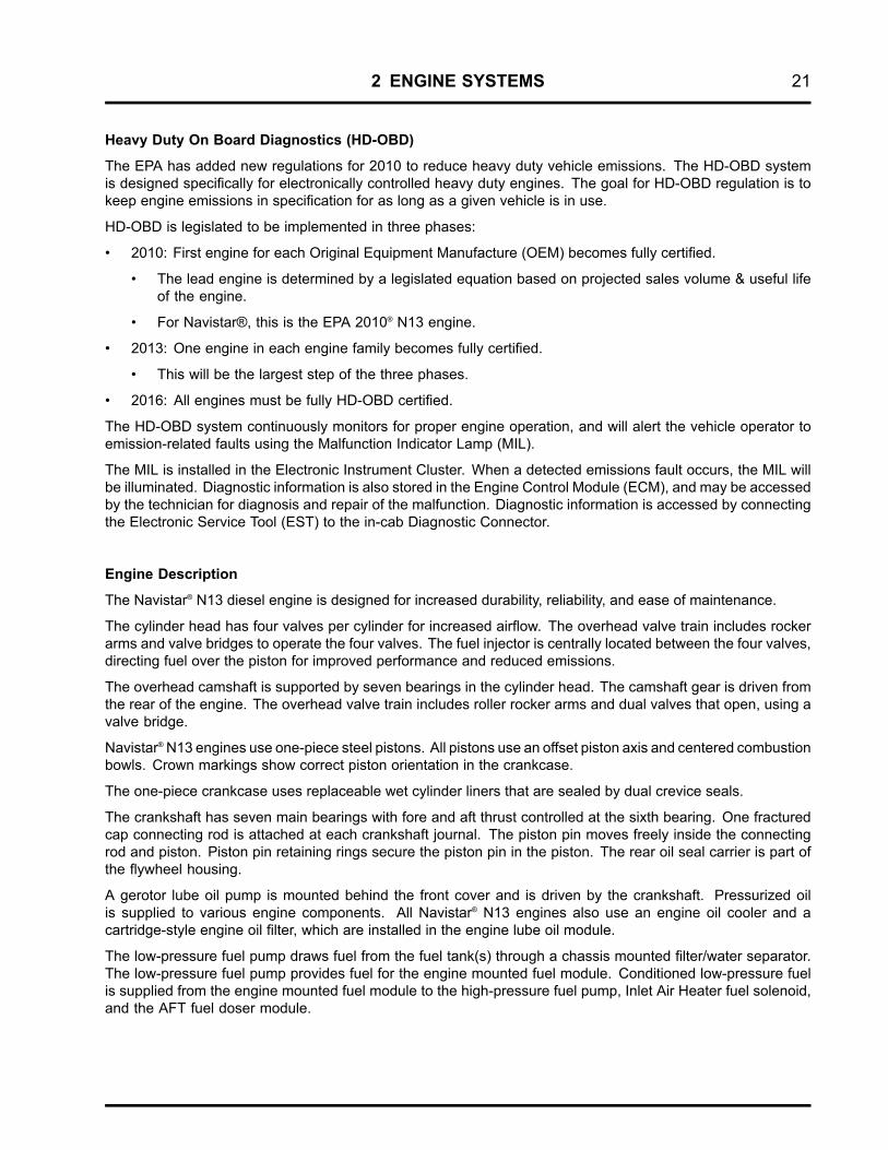
Heavy Duty On Board Diagnostics (HD-OBD)
The EPA has added new regulations for 2010 to reduce heavy duty vehicle emissions. The HD-OBD systemis designed specifically for electronically controlled heavy duty engines. The goal for HD-OBD regulation is tokeep engine emissions in specification for as long as a given vehicle is in use.
HD-OBD is legislated to be implemented in three phases:
• 2010: First engine for each Original Equipment Manufacture (OEM) becomes fully certified.
• The lead engine is determined by a legislated equation based on projected sales volume & useful lifeof the engine.
• For Navistar®, this is the EPA 2010® N13 engine.
• 2013: One engine in each engine family becomes fully certified.
• This will be the largest step of the three phases.
• 2016: All engines must be fully HD-OBD certified.
The HD-OBD system continuously monitors for proper engine operation, and will alert the vehicle operator toemission-related faults using the Malfunction Indicator Lamp (MIL).
The MIL is installed in the Electronic Instrument Cluster. When a detected emissions fault occurs, the MIL willbe illuminated. Diagnostic information is also stored in the Engine Control Module (ECM), and may be accessedby the technician for diagnosis and repair of the malfunction. Diagnostic information is accessed by connectingthe Electronic Service Tool (EST) to the in-cab Diagnostic Connector.
Engine Description
The Navistar® N13 diesel engine is designed for increased durability, reliability, and ease of maintenance.
The cylinder head has four valves per cylinder for increased airflow. The overhead valve train includes rockerarms and valve bridges to operate the four valves. The fuel injector is centrally located between the four valves,directing fuel over the piston for improved performance and reduced emissions.
The overhead camshaft is supported by seven bearings in the cylinder head. The camshaft gear is driven fromthe rear of the engine. The overhead valve train includes roller rocker arms and dual valves that open, using avalve bridge.
Navistar®N13 engines use one-piece steel pistons. All pistons use an offset piston axis and centered combustionbowls. Crown markings show correct piston orientation in the crankcase.
The one-piece crankcase uses replaceable wet cylinder liners that are sealed by dual crevice seals.
The crankshaft has seven main bearings with fore and aft thrust controlled at the sixth bearing. One fracturedcap connecting rod is attached at each crankshaft journal. The piston pin moves freely inside the connectingrod and piston. Piston pin retaining rings secure the piston pin in the piston. The rear oil seal carrier is part ofthe flywheel housing.
A gerotor lube oil pump is mounted behind the front cover and is driven by the crankshaft. Pressurized oilis supplied to various engine components. All Navistar® N13 engines also use an engine oil cooler and acartridge-style engine oil filter, which are installed in the engine lube oil module.
The low-pressure fuel pump draws fuel from the fuel tank(s) through a chassis mounted filter/water separator.The low-pressure fuel pump provides fuel for the engine mounted fuel module. Conditioned low-pressure fuelis supplied from the engine mounted fuel module to the high-pressure fuel pump, Inlet Air Heater fuel solenoid,and the AFT fuel doser module.

22 2 ENGINE SYSTEMS
The high-pressure fuel system is a direct fuel injected common-rail system. The common-rail includes ahigh-pressure fuel pump, two fuel rail supply lines, fuel rail, six fuel injectors, and pressure relief valve.
The fuel injectors are installed in the cylinder head under the valve cover and are electronically actuated by theECM.
Navistar® N13 engines use a dual stage, fixed geometry turbocharger assembly. Each stage includes a ChargeAir Cooler (CAC). The High Pressure (HP) turbocharger includes a pneumatically operated wastegate. The LowPressure Charge Air Cooler (LPCAC) is mounted on the lower right side of the engine, and uses the enginecooling system to regulate charge air temperatures. The High Pressure Charge Air Cooler (HPCAC) is mountedin front of the engine cooling package. The HPCAC is an air-to-air type cooler, and requires no connections tothe engine's cooling system.
The Exhaust Gas Recirculation (EGR) system circulates cooled exhaust into the air inlet duct. The dual stageEGR cooler provides regulated cooling of the EGR gases before entering the air inlet duct. This cools thecombustion process, and reduces Nitrogen Oxides (NOX) emissions.
The open crankcase breather system uses a centrifugal Crankcase Oil Separator (CCOS) to return oil mist tothe crankcase, and vent the cleaned crankcase gasses to the atmosphere. The CCOS is part of the oil module.The breather system has been redesigned, and uses no crankcase breather filter or external piping. Blowbygases enter the CCOS through the side of the crankcase.
The Inlet Air Heater system warms the incoming air supply during engine cranking and several minutes aftercold engine start up to help reduce emissions.
The Navistar® Engine Brake by Jacobs® is optional for Navistar® N13 engine displacements. The engine brake isa compression release system that provides additional vehicle braking performance. The operator can controlthe engine brake for different operating conditions.
Optional Equipment
Optional cold climate features available are an oil pan heater and a coolant heater. Both heaters use an electricelement to warm engine fluids in cold weather.
The oil pan heater warms engine oil to ensure optimum oil flow to engine components.
The coolant heater warms the engine coolant surrounding the cylinders. Warmed engine coolant increases fueleconomy and aids start-up in cold weather.
Chassis Mounted Equipment
• The chassis mounted fuel filter/water separator removes a majority of the water and foreign particles thatmay enter the fuel system from the supply tank(s). This filter works with the engine mounted fuel module toeliminate foreign matter and moisture from the fuel before entering the fuel injection system.
• The Low Temperature Radiator (LTR) regulates the temperature of the LPCAC and the low-temperaturestage of the EGR cooler. The LTR is mounted in front of the radiator cooling package, and requiresconnections to the engine cooling system.
• The HPCAC lowers temperature after the air is compressed by the turbochargers, and has no connectionsto the engine cooling system. The HPCAC is an air-to-air cooler. The HPCAC is mounted in front of theradiator cooling package.

2 ENGINE SYSTEMS 23
• The Diesel Oxidation Catalyst (DOC) oxidizes hydrocarbons and carbon monoxide, provides heat forexhaust system warm-up, aids in temperature management for the Diesel Particulate Filter (DPF), andoxidizes NO into NO2 for passive DPF regeneration. The DOC is monitored by the Aftertreatment ControlModule (ACM) using one Diesel Oxidation Catalyst Inlet Temperature (DOCIT) sensor positioned at theDOC inlet, and one Diesel Particulate Filter Inlet Temperature (DPFIT) sensor positioned at the DPF inlet.
• The DPF temporarily stores carbon-based particulates, oxidizes stored particulates, stores non-combustibleash, and provides required exhaust back pressure for proper engine performance. The DPF is monitored bythe ACM using the DOC / DPF temperature sensor module installed on the DPF, and the Diesel ParticulateFilter Differential Pressure (DPFDP) / outlet pressure sensor installed on or near the DPF.
• The Selective Catalyst Reduction (SCR) catalyst oxidizes Nitrogen Oxides (NOx) into Nitrogen gas andwater. The SCR catalyst is monitored by the ACM using a NOx IN sensor module installed after the HPturbocharger outlet pipe, and a NOx OUT sensor module installed after the outlet of the SCR catalyst. Anammonia (NH3) sensor provides feedback to the ACM related to Diesel Exhaust Fluid (DEF) injection intothe SCR catalyst.

24 2 ENGINE SYSTEMS
Air Management System
Figure 6 Air Management System
1. Exhaust Gas RecirculationTemperature (EGRT) sensor
2. Intake Manifold Pressure (IMP)sensor
3. Engine Throttle Valve (ETV)4. Charge Air Cooler Outlet
Temperature (CACOT) Sensor5. EGR cooler
6. Intake Manifold Temperature(IMT) sensor
7. EGR valve8. Turbocharger 2 Compressor
Inlet Sensor (TC2IS)9. Air filter housing10. Humidity Sensor (HS) / Inlet Air
Temperature (IAT) sensor
11. Low Pressure (LP) turbocharger12. Exhaust Back Pressure Valve
(EBPV)13. Oxygen Sensor (O2S)14. High Pressure (HP) turbocharger15. HP turbocharger wastegate16. Exhaust manifold17. Cylinder head

2 ENGINE SYSTEMS 25
Airflow
Air flows through the air filter assembly and enters the Low-Pressure (LP) turbocharger. The LP turbochargerincreases air pressure and temperature before entering the Low Pressure Charge Air Cooler (LPCAC). Cooledand compressed air then flows from the LPCAC into the High Pressure (HP) turbocharger (compressor inlet). Hotand highly compressed air flows from the HP turbocharger (compressor outlet) into the High Pressure Charge AirCooler (HPCAC) where it is cooled, and into the intake throttle duct, and continues through the Engine ThrottleValve (ETV). The HP and LP turbochargers can increase pressures up to 345 kPa (50 psi).
If the Exhaust Gas Recirculation Valve (EGRV) is open, exhaust gases pass through the EGR cooler and intothe intake throttle duct where it is mixed with filtered air. This mixture flows into the intake manifold, and thenthe cylinder head. The intake manifold is an integral part of the cylinder head casting.
During cold weather, the Inlet Air Heater system activates the heater element, vaporizing and igniting smallquantities of fuel into the air inlet duct.
After combustion, exhaust gases exit through the cylinder head exhaust valves and ports. The exhaust gas isforced through the exhaust manifold where, depending on EGRV position, it is split between the EGR systemand the exit path through the HP turbocharger, LP turbocharger, and Exhaust Back Pressure Valve (EBPV).
The EBPV is operated by the Air Control Valve (ACV), a pneumatic actuator. When the ACV is applied, theEBPV restricts flow and increases exhaust back pressure. Operation of the EBPV is controlled by the ECMusing the ACV and the Turbocharger 1 Turbine Outlet Pressure (TC1TOP) sensor. When the EBPV is opened,exhaust back pressure is released.
Exhaust gases exiting the engine flow through the EBPV, then through the vehicle Aftertreatment (AFT) system,and out the exhaust tail pipe.

26 2 ENGINE SYSTEMS
Turbochargers
Figure 7 High and Low Pressure Turbocharger Components – Inner and Outer views
1. High Pressure (HP) turbochargercompressor inlet
2. HP turbocharger turbine inlet3. LP turbocharger turbine outlet4. HP turbocharger5. HP turbocharger wastegate
actuator
6. Low Pressure (LP) turbocharger7. Turbocharger oil supply tube8. LP turbocharger compressor
outlet9. Oil return tube10. LP turbocharger compressor
inlet
11. HP turbocharger compressoroutlet
Navistar® N13 engines are equipped with a pneumatically regulated two-stage turbocharger system. The HighPressure (HP) and Low Pressure (LP) turbochargers are installed in parallel on the right side of the engine.
Intake air flow: Filtered air enters the LP compressor, where it is compressed and directed to the LowPressure Charge Air Cooler (LPCAC). Cooled compressed air then enters the HP compressor, where it isfurther compressed and directed into the High Pressure Charge Air Cooler (HPCAC). Compressed air thengoes through the Engine Throttle Valve (ETV) and the intake throttle duct. This system provides high chargeair pressure to improve engine performance and to help reduce emissions.
Exhaust gas flow: The HP turbocharger is connected to the exhaust manifold through the HP turbine inlet.Exhaust gases exit the HP turbine outlet and are directed to the LP turbine inlet. The HP turbocharger isequipped with a wastegate, which is controlled by a pneumatic actuator. The HP turbocharger wastegate isused to regulate boost by controlling the amount of exhaust gas that bypasses the turbine of the turbocharger.
2 ENGINE SYSTEMS 27
When boost demand is low, the wastegate is opened, allowing part of the exhaust gas flow to bypass the HPturbine.
Control system signals associated with the HP and LP turbochargers have been renamed for 2010.
All signals related to the LP turbocharger are designated as Turbocharger 1 (TC1) signals, and are identifiedbelow:
• Turbocharger 1 Turbine Outlet Pressure (TC1TOP)
All signals associated with the HP turbocharger are designated as Turbocharger 2 (TC2), and are identifiedbelow:
• Turbocharger 2 Wastegate Control (TC2WC)
• Turbocharger 2 Compressor Inlet Sensor (TC2CIS)
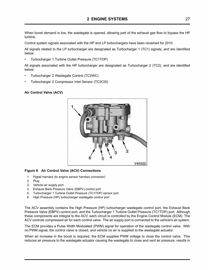
Air Control Valve (ACV)
Figure 8 Air Control Valve (ACV) Connections
1. Pigtail harness (to engine sensor harness connector)2. Plug3. Vehicle air supply port4. Exhaust Back Pressure Valve (EBPV) control port5. Turbocharger 1 Turbine Outlet Pressure (TC1TOP) sensor port6. High Pressure (HP) turbocharger wastegate control port
The ACV assembly contains the High Pressure (HP) turbocharger wastegate control port, the Exhaust BackPressure Valve (EBPV) control port, and the Turbocharger 1 Turbine Outlet Pressure (TC1TOP) port. Althoughthese components are integral to the ACV, each circuit is controlled by the Engine Control Module (ECM). TheACV controls compressed air for each control valve. The air supply port is connected to the vehicle's air system.
The ECM provides a Pulse Width Modulated (PWM) signal for operation of the wastegate control valve. Withno PWM signal, the control valve is closed, and vehicle no air is supplied to the wastegate actuator.
When an increase in the boost is required, the ECM supplies PWM voltage to close the control valve. Thisreduces air pressure to the wastegate actuator causing the wastegate to close and vent air pressure, results in