Embed Size (px)
Citation preview
TABLE OF C O N T E N T S
SECTION A-COIN AND CRE.DIT EQUIPMENT
SECTION B-SELECTOR SWITCH AND ELECTRIC SELECTOR
SECTION C - RECORD CHANGER ADJUSTMENTS
SECTION D -CABINET /
SECTION E -SEQUENCE OF OPERATIONS
SECTION F -TROUBLE SHOOTING
SECTION G -ELECTRICAL AND SOUND SYSTEMS
THE WURLITZER COMPANY NORTH TONAWANDA. NEW YORK
SECTION A
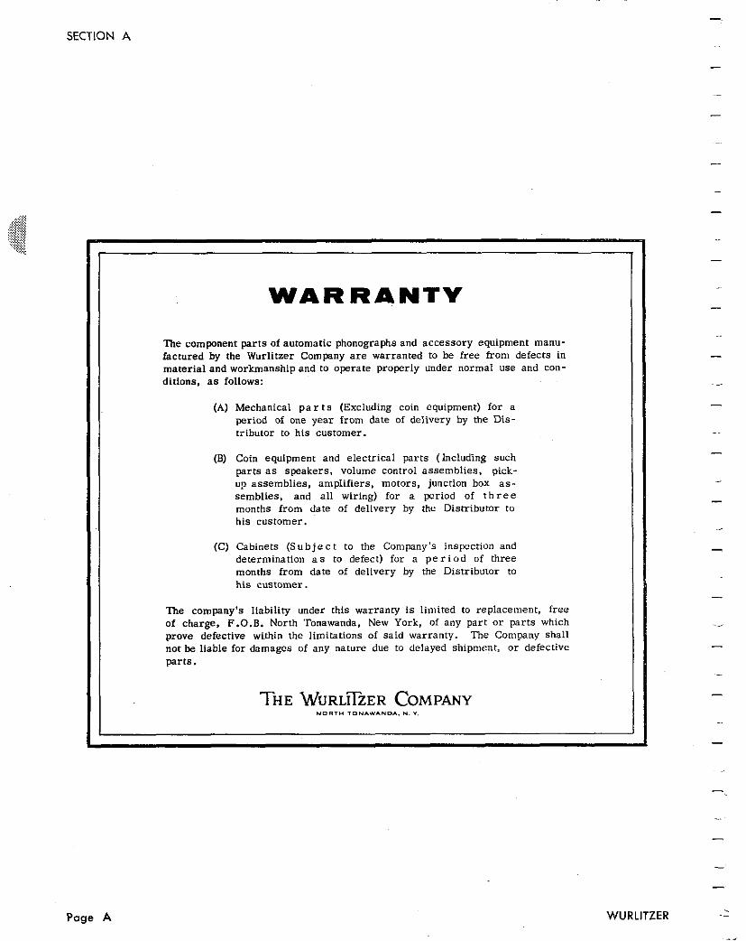
WARRANTY
The component par t s of automatic phonographs and accessory equipment manu- factured by the Wurlitzer Company a r e warranted to be f ree from defects in mater ial and workmanship and to operate properly under normal use and con- ditions, a s follows:
(A) Mechanical p a r t s (Excluding coin equipment) for a period of one year from date of delivery by the Dis- tributor to his customer.
(B) Coin equipment and eiecmical par ts (Including such parts a s speakers , volume control assemblies , pick- up assemblies , amplifiers, motors, junction box a s - semblies, and a l l wiring) for a period of t h r e e months from date of delivery by the Distributor to his customer.
(C) Cabinets ( S u b j e c t to the Company's inspection and determination a s to defect) for a p e r i o d of three months from date of delivery by the Distributor to h i s customer.
The company's liability under this warranty i s limited to replacement, f r e e of charge, F.O.B. North Tonawanda. New York, of any par t o r par t s which prove defective within the limitations of said warranty. The Company shal l not be liable for damages of any nature due to delayed shipment, o r defective
THE WURL~~ZER COMPANY N O R T H T O N I W I U D * . U. v.
- -
WURLITZER -- . Page A
- -
SECTION A
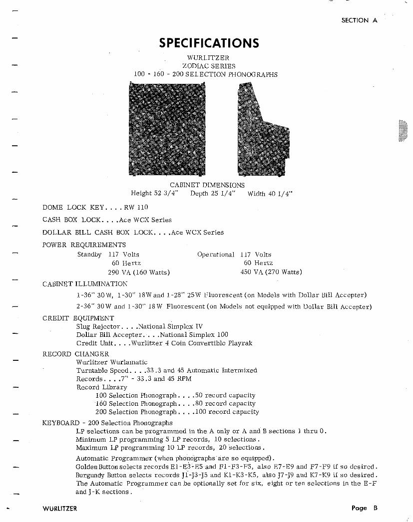
SPECIFICATIONS WURLITZER
ZODIAC SERIES 100 - 160 - 200 SELECTION PHONOGRAPHS
CABINET DIMENSIONS Height 52 3/4" Depth 25 1/4" Width 40 1/4"
DOME LOCK KEY. . . . RW 110
CASH BOX LOCK. . . .Ace WCX Series
DOLLAR BILL CASH BOX LOCK. . . .Ace WCX Series
POWER REQUIREMENTS Standby 117 Volts Operational 117 Volts
60 Hertz 60 Hertz 290 VA (160 Watts) 450 VA (270 Watts)
CABINET ILLUMINATION
1-36" 30 W, 1-30" 18W and 1-28" 25W Fluorescent (on Models with Dollar Bill Accepter)
2-36" 30W and 1-30" 18 W Fluorescent (on Models not equipped with Dollar Bill Accepter)
CREDIT EQUIPMENT Slug Rejector. . . .National Simplex IV Dollar Bill Accepter. . . .National Simplex 100 Credit Unit. . . .Wurlitzer 4 Coin Convertible Playrak
RECORD CHANGER Wurlitzer Wurlamatic Turntable Speed. . . .33.3 and 45 Automatic Intermixed Records. . . .7" - 33.3 and 45 RPM Record Library
100 Selection Phonograph. . . .50 record capacity 160 Selection Phonograph. . . .80 record capacity 200 Selection Phonograph. . . .I00 record capacity
KEYBOARD - 200 Selection Phonographs LP selections can be programmed in the A only or A and B sections 1 thru 0 . Minimum LP programming 5 LP records, 10 selections. Maximum LP programming 10 LP records, 20 selections.
Automatic Programmer (when phonographs a r e s o equipped). GoldenButtonselects records ~ 1 - ~ 3 - ~ 5 a n d El-F3-F5, also E7-E9 and F7-F9 if s o desired. Burgundy Button selects records J1-J3-J5 and K1-K3-K5, also J7-J9 and K7-K9 if s o desired. The Automatic Programmer can be optionally se t for six, eight or ten selections in the E-F and J-K sections.
WURLITZER Page B
SECTION A
KE1'BOARD - 160 S e l e c t i o ~ l Phonographs LP se lcc t io i l s c a n b e p r o g r a m m e d in the 1 only o r 1 and 2 s e c t i o n s A t h r u V . Min imum LP progra l i ln l ing 1 0 LP r e c o l d s , 20 s e l e c t i o n s . Max imum LP p1:ogramming 20 LP r e c o r d s , 40 s e l e c t i o n s .
KEYBOARD - 100 S e l e c t i o l ~ Phonographs LP se lec t ions c a n be progr i lmined in t h e A only o r A and B s e c t i o n s 1 t h r u 0 . Min imum LP p r o g r a m m i n g 5 LP r e c o r d s , 1 0 s e l e c t i o n s . Max imum LP p r o g r a m m i n g 1 0 LP r e c o r d s , 20 s e l e c t i o n s l
!::::: ....... ........ ......... ......... .......... .......... SOUND SYSTEM .......... .......... .......... .......... ......... . ......... ......... ........ ....... Solid S ta t e A m p l i f i e r . . W u r l i t z e r Mode l 5 5 1 ...... ..... Power Supply . . .Wur l i t ze r Model 552
Pickup. . .As ta t i c Stylus . .Dual T i p Diamond .7 Mil Power Output t o t a l . . . 80 wa t t s mus ic power Output Impedance . . .Multiple t a p low impedance plus cons tan t vo l t age .
CABINET SPEAKERS 2 - 12" Lower - Range S p e a k e r s 2 - 6" Upper - Range S p e a k e r s
ZODIAC ACCESSORIES
Remote Volume Con t ro l Kit 219 Micropl?one Kit 220 S tepper , 100 and 200 Select ion, Model 268 S tepper , 160 Select ion, Mode l 269 I ~ i c o m e Compute r , Model 207 \\'all Box, 200 Selectioil (with S p e a k e r s & Golden Bar), Model 5220 \Val1 Box, 200 Se lec t ion (without S p e a k e r s o r Golden Bar), Model 5220.4 Wall Box, 100 Se lec t ion (with S p e a k e r s & Golden Bar), Model 5225 \\'all Box, 100 Select ion (without S p e a k e r s o r Golden Bar), Model 5225A \\'all Box Bar Mounting Bracket (Chrome) , Kit 191 \Val1 Box Bar Mounting Bracket (Aluminum), Kit 192 Wal l Box Mounting Plate, 5220-5225 Wal l Box Mounting Pla te , 5220A-5225A Wal l Box Booster T r a n s f o r m e r , Model 222B Speaker , Extender , Model 51258 Speaker , Direc t ional , Model 5126 Speaker , a Model 5133
P a r t N o . 136930 P a r t No. 1 3 6 9 3 1 P a r t No . 137058 P a r t No. 137059 P a r t No. 132969 P a r t No. 125555 P a r t No. 125557 P a r t No . 125547 P a r t No . 125549 P a r t No. 126469 P a r t N o . 126470 P a r t N o . 126984 P a r t No. 126985 P a r t N o . 126390 P a r t N o . 117050 P a r t N o . 117136 P a r t No. 131592
Page C
SECTION A
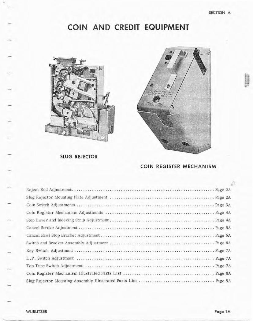
COlN AND CREDIT EQUIPMENT
SLUG REJECTOR
COlN REGlSTER MECHANISM
.> . ................................................................ Ileject Rod Adjusment Page 2A
............................................... Slug Rejectm Mounting Plate rldjustrnent Page 2A
.............................................................. Coin Switch Adjustments Page 3A
................................................. Coin Register Mechanism rldjustments Page 4.A
............................................... Stop Lcver and Indexing Str ip .%djustmenr Page 4A
CancelSl-roke Adjustment ...........,........~........................................Pa ge 5A
................................................. Cancel Pawl Stop Bracket -4djustmem.. Page 6A
............................................... Stvit'cl? and Bracket: Assembly Arijustment Page 6A
............................................................. Key Swi tch Adjustment.. Fagc 7A
.............................................................. L.P. Switch Adjustment Page 7A
......................................................... Top Tune Switch Adjustment.. Page 7A
......................................... Coin Register Mechanism Illustrated Parts List Page 8A
.................................. Slug Rejector Mounting Assembly Illustrated Parts Lis t Page 9A
WU RLITZER Page 1 A
SECTION A
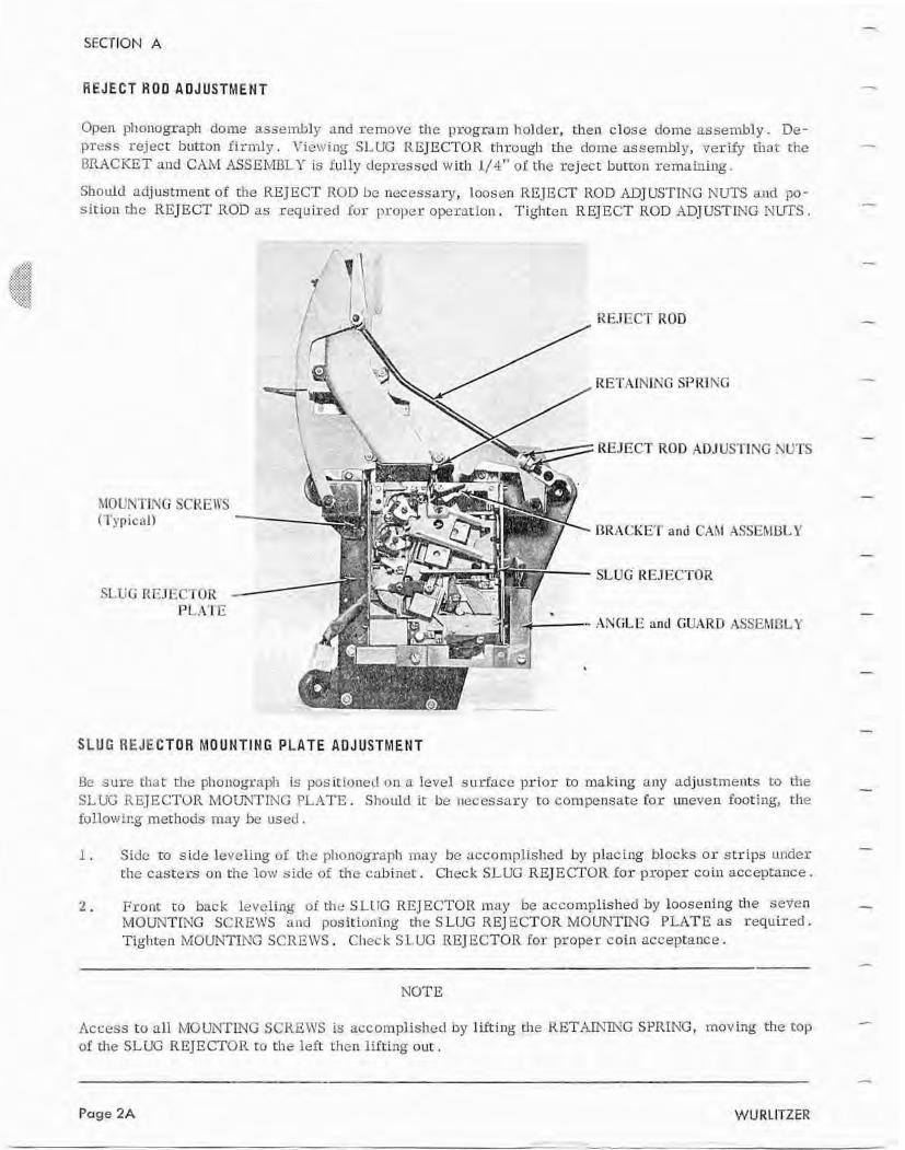
REJECT H O D ADJUSTMENT
Open phonograph dome assembly m d rcmuvc t h e program holder, then close dome assembly . De- press reject button f i rmly. Vicwing SLUG REJECTOII through dome asscmhly, verify thaE the RPAC.KE?" and .CAM I1SS E h a L I' is iu l ly depressed with 1/ 4"" of the reject button semahiilg.
Should adjustment of the REJECT IiOn be necessary, loosen REJECT ROD ADJUSTlNG NUTS u d pa- s ition the REJECT ROD as required Iur proper: operatiail . Tighten REJECT ROD ADJUSTING MLlTS .
SLUG I:EJEC?'Ol? - PL;l'KE
/ RETAINING SPRING
REJECT ROD ADJUSTING NUTS
BRACKET and CAM ,4SSEMBlLY
SLUG REJECTOR
ANGLE and GUHRIS :4SSERIRLY
SLUG REJECTOR MOUNTING PLATE ADJUSTMENT
Be sure dut rhe phonograph is posisioned on a level surface pr ior to making ally adjusrments :so the SL LiG RFJE CTOR MOUNTING FlL14TE . SI~ould ic: be necessary to compensate f o r uneven fouting, the f o l l o v ~ i ~ g merhods may be u s eri .
1 . Side t o s ide leveling of tho phonograph may be a~complkshed by placing blocks o r strips under rhe casters on the low side of the cAiner:. Check SLUG REJECTOR f o r proper cohl acceptance.
2 . Fronr t o back leveling uE the SLlTG REJECTOR map he accomplished by loosening tlle seven MOUNTING SCREWS and pasitluning the S LUG RE] ECTOR MOUNTING PLATE ns required. Tighten MOUNTING SCREWS. Cllec k SLUG REJECTOR for proper coin acceptance.
NOTE
Access to all MU UNTLNG SCREWS is accomplisl-red by lifting the R E T A a G SPRING, mov Lig the top of the SLUG REJECTOR to the left then lifting out.
SECTION A
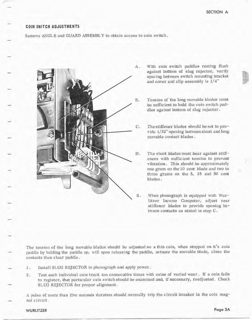
C O I N SWITCH AUJUSTMENKS
Iiernove ANGLE and GUARD ASSEMBLY to abtain access to coin swi tch .
A . Wlth coin switch paddles resting flush against bottom of slug rejector, verify spacing betweell switch mounting bracket and cover and clip assembly is 1/4"
I3 . Tern ion of the long movable bli~rlcs mcrst be sufficient. to I-told the cam switch pad- dles against bottom of slug rejector.
C . The s t B e n e r blades should be se t to pro - vide 1/32 " opening b e t ~ ~ e c n short and long inovable contact blades .
I3. The s h o r t blades must bear against stiff - eners wit11 sufficient tension t o prevent vibration , This st~oulcl be approximately one gram on the 10 cerit blade and two to three grams on the 5, 25 and 50 cent blades.
E . Whenplionogapl~ Is equippecl with Wur- litzer Income Computer, adjust rear stiffener Hades to provide opening be- tween contacts as stated i n step C .
The tension of the long movablc hlacles shot~ld be adjusted so a thin coin, wvhcn stopped on i t ' s coin paddle by holding the paddle up, w i l l upon releasing the paddle, actuate the movable hlade, close the conracts then clear paddle.
1 . Znstall SLUG REJECTOR in phonograph and apply power.
2 . Test each individual coin track ten consecutive times with coins of varied wear. If a coin fails to register, that pastic ulrtr. coin scvitcli sllould be exa~n ined and, if necessary, readj usred . Check SLUG KEJECTOR f o r praper alignment.
h pulse of more than five secoilds duration shouPr1 llarn~all y t r i p the c ircuit: breaker in the coin mag- net c i rcu i t .
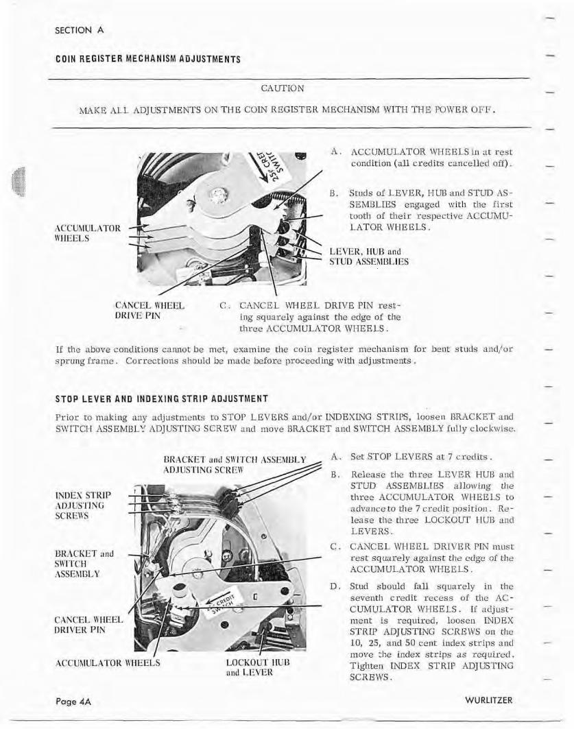
COIN REGISTER MEGHANISM ADJUSTMENTS
MAKE ALL ADJUSTMENTS ON W E COIN REGISTER MECHANlSM WITH THE PCIWER OFF.
A . ACCUMULATOR XrH B ELS in ar rest conditioi-t (all credits cancelled off).
l3. Sruds of LEVER, HUB and STUD AS- SEMBLIES engaged with the first tooth of their respective ACCUMU- LATOR WHEELS.
LEVER, HUE and S'TED ASSEXI~I,I ES
CANCEL IIfIIEEL C . CANCEL WHEEL DRIVE PTN resc- DKIL'E PIN ing squarely against the edge af [I-te
cl~rce ACCUMULATOR \W-EELS .
If the ~ o v e conditions cannot be met, exa~niric the coin register meclanism for bent studs and/or sprung irame . Corrections should be made before ~~roceerling with ndj ustrncnts .
STOP LEVER AND INISEXING STRIP ADJUSTMENT
Prior to making any adjustments to STOP LEVERS and/or INDEXING STRIPS, loosen RRACKET and SWITCI-I ASSEMBLY ADJUSTING SCREW and move BRACKET and SWITCH ASSEM13I-Y fully clockwise.
BRACKET nnrl S\\'I'I'ClI ASSERIULY ,
INDEX STRIP :\I>.TUS?'I NF SCREII'S
URACKET and SITITCH :\SSEXIGLY
CAKCEI, \YIIEEL DRlVEIt PIN
.ACCUMULATOR \YI-IEELS LOCKOCI I IU 13 and LT;.\'EII
Set STOP LEVERS ar 7 crcclits .
Release the three LEVER HUB and STUD ASSEMBLIES allawlng t11e three ACCUMULATOR \VHEEIS to advance to the 7 credit posirion. Re- lease the three LOCKOUT 1-11113 zuld LEVERS . CANCEL WHEEL DRIVER PIN must rest squarely against the edge of the ACCUMULATOR WHEELS.
Stud sbuulcl Iall squarely i n the seventh c r ed i t rccess o f the 11C- CUMUWTOR WI-[EELS . If adjust- ment: is required, loosen INDEX STRLP ADJUSTING SCREWS on the 10, 25, and 50 cenr index strips and move 91c index strips as required, Tighten INDEX STRIP ADJUSTING SCREWS.
Page 4A WU RLITZER
SECTION A
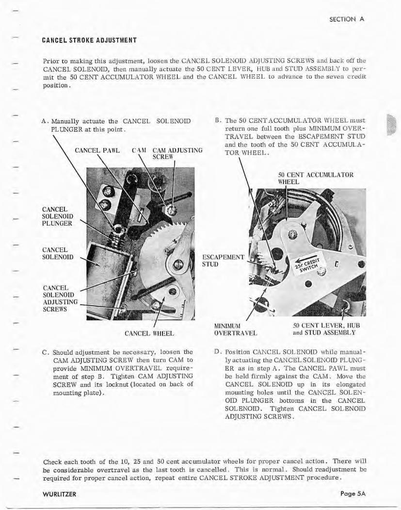
CANCEL STROKE ADJUSTMENT
Prior to making this adjustment, l ~ o s e n the CANCEL SOLEiilOIC, rIJlJlrSTmG SCREWS and back off r l~e CANCEL SOLENOID, then manually actuate t!ne 50 CENT LETTER, HLIE and STUD ASSEMBLY to per- mit the 50 CEhT ACCUMULATOR WHEEL and ~l-re CANCEL IWEEI, to advance ta the seven credit position .
A . Manually actuate the CANCEL SOLENOID I3 . The SO CENT ACCUMULATOR WI-IEEL must PLUNGER at this point" re turn one full tooth plus MNIMUM OVER-
\ TKAVEL between the ESCAPEMENT STUD and the tooth af the 50 CENT ACCUMULA-
CANCEL PAWL C.4 hI CAM ADJUSTING \ \ TOR WHEEL.
I \
/ CANCEL WllEEL
\ 50 CENT ACCUhIULATOR IC'MEEL
C. Should adjustment be necessary, loosen the CAM ADJUSTING SCREW then turn CAM to provide MINIMUM OVERTRAVEL require- ment of step B. Tighten CAM ADJUSTING SCREW and its locknut (located on back of mounting plate) .
hll NIMUM 50 CENT LEI'ER, llUB OVERTRAVEL and STUD ASSEhlI?LY
Position W C EL SOLENOID while manual - ly ac~uachg the CAN CGL SOL ENOID PLUNG - ER as in step A . The CANCEL PAWL must be held firmly against the CAM. Move the CANCEL SOLENOID up in its elongated mo~mting holes until the CANCEL SOLEN- OID PLUNGER bottoms in t he CANCEL SOLENOID. Tighten CANCEL SOLENOID ADJUSTING S CREWS .
Check each tooth of the 10, 25 and 50 cent accumulator wheels far proper cancel action. There w i l l be cons idexable avertravel as the last tooth is cancelled . This is normal . Should readjustment be required for proper cancel action, repeat ent i re CANCEL STROKE ADJUSThdXhT procedure.
WURLITZER Page 5A
SECTION A
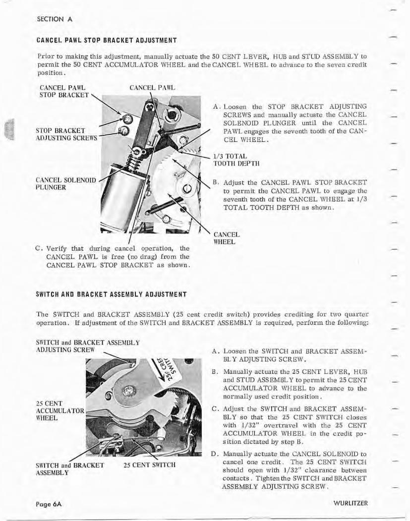
C A N C E L PAWL STOP BRlllCKET ADJUSTMENT
P r i o r to making this adjustment, manuaIIy actuate the 50 CENT LEVER, ML3 and STUD ASSEMBLY to permit t he 50 CENT ACCUMULATOR WHEEL and the CANCEL IW EEL to advance to the seven credit position.
CANCELPAWL STOP BRACKET \
C
STOP BRACKET ADJUSTING SCREWS '
CANCEL SOLENOID PLUNGER
CANCEL PANL
A . Loosen the STOP BKACKET ADJUSTING SCREWS and manually acruatc the CANCEL SOLENOLD PLUNGER until the CANCEL PAWL engages the seventll toot11 of tlie CAhT- GEL WIIEEL.
1/3 TOTAL TOOTH DEPTH
B . Adjust the CANCEL PAWL STOP BRACKET to permit the PAWL to engage the seventh tooth of the CANCEL WI-IEEL at 1/3 TOTAL TOOTH DEPTI-J as shown.
CANCEL I WHEEL
C. Verify that during cancel operation, the CANCEL PAWL is free (no drag) from the CANCEL PAWL STOP BRACKET as shown.
SWIT CH AND BRACKET ASSEMBLY ADJUSTMENT
The SWITCH and BRACKET ASSEMBLY (25 cent credit switch) provides crediting for two quarter operation. If adjustment of the SWITCH and BRACKET ASSEMBLY is required, perforin the following:
SWITCH and BRACKET ASSEMBLY ADJUS'PING SCRERf ,
r , 35 CENT
SIYITCH and BRACKET 25 CEKT SWI'I'CII ASSEMBLY
Loosen the SWITCH ancl BRACKET ASSEM- BLY AbJLKTiNG SCREW.
Manually actuate the 25 CENT LEVER, HUB and STUD ASS EMflLY to pel'rnit the 25 CENT ACCUMULATOR WHEEL to advance t o the normally used credit posi t ian.
Adjust the SWITCH and BRACKET ASSEM- BLY so that the 25 CENT SUIITCH closes with 1/32" overtravel with rhe 25 CENT ACCUMULATOR WIJEEL in the credit po- s ition dictated by s tep B . Manually actuate the CANCEL SOLENOID to cancel one credit. The 25 CENT SWITCI-I should open will1 1/32" clearance between contacts . Tighten the SWIT CI-I and B U C K E T ASSEMBLY ADJUSTING SCREW.
Page 6A WU RLITZER
SECTION A
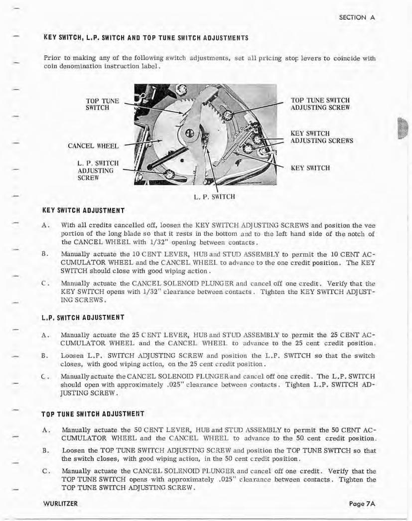
KEY SWITCH, L , P , SWlTCH AND TOP TUNE SWITCH ADJUSTMENTS
Prior to making any of the following switch adjustments, set all pricing s t g levers to coincide with coin denomination insmuccion labe1 .
TOP TUNE SWITCH
CANCEL \'/HEEL
TOP TUNE SWITCH ADJUSTlNG SCREW
KEY SWITCH ADJUSTING SCREWS
KEY SlYITCH
KEY SWITCH AUJUSTMENT
A . With all credits cancelled off, loosen the KEY SWITCH -4DJ USTING SCREWS and position the vee portion af the long blade so that it rests in the bonom nncl to the left hand side of rhe notch of the CANCEL WHEEL with 1/32" opening between con~acrs .
I3. Manually actuate the 10 CENT LEVER, HUE and STUD ASSEMBLY to permit the 10 CENT AC- CUMULATOR WHEEL and the CANCEL WI-IEEL ta advance t o the one credit position. The KEY SWTCH should clase with good wiping action.
C . rvI%nuRUy actuate the CANCEL SOLENOID PLUNGER and cancel off one credit. Verify that the KEY SWITCH opens wit11 1/32" clearance between contacts . Tighten the KEY SWITCH ADJUST- ING SCREWS.
L,P, SWITCH ADJUSTMENT
A . Manually actuate the 25 C ENT LEVER, HUB and STUD ASSEmLY to permit the 25 CENT AC - CUfvZULATOR WHEEL and the CANCEL IVHEEL to advance to the 25 cent credit position.
B. Loosen L .P. S W C H ADJUSTLYG SCREW and position the L .P. SWITCH so rhat the switch closes, with good wiping action, on the 25 cent credit position.
C . Manually acmate the CANCEL SOLENOID PLUNGER nnci onncel off one credit. The L . P . SWITCH should open with approximately ,025" clearance between contacts . Tighten L .P. SWITCH AD- JUSTING SCREW.
TOP TUNE SWITCH ADJOSTMEHT
A . Manually actuate the 50 CENT LEVER, HUB and STUE ASSEMBLY to permit the 50 CENT AC- CUMULATOR WHEEL and the CANCEL WHEEL t o advance to tl1e 50 cent credit position.
B. L o o s e n ~ e T O P T ~ S W I T C H l l l D J v S T I N G S C R E W m d p o s i t i o n t h e T O P T U N E S W l T C H s o t b a t : the switch closes, with good wiping action, in the 50 cent credit positian,
C , Manually actuate the CANCEL SOLENOID PLUNGER and cancel off one credit. Verify that the TOP TUNE SWITCH opens wirh approximately ,025" clearance behveen contacts . Tighten the TOP TUNE SWITCH ADJUSTING SCREW.
SECTION A
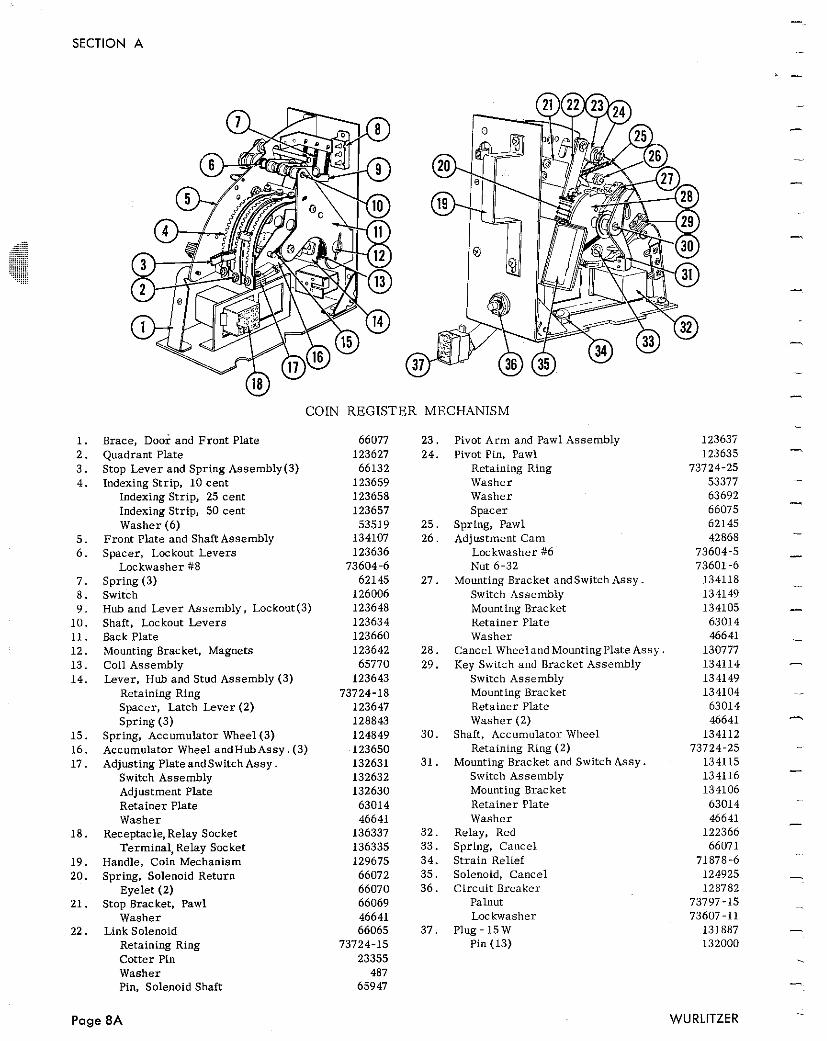
COIN REGIS?
Brace, Door and Fron t Plate Quadrant Plate Stop Lever and Spring Assembly(3) Indexing Strip, 10 cent
Indexing Strip, 25 cent Indexing Strip, 50 cent Washer (6)
Front Plate and Shaft Assembly Spacer, Lockout Levers
Lockwasher #8 Spring (3) Switch Hub and Lever Assembly, Lockout(3) Shaft, Lockout Levers Back Plate Mounting Bracket, Magnets Coil Assembly Lever, Huh and Stud Assembly (3)
Retaining Ring Spacer, Latch Lever (2) Spring (3)
Spring, Accumulator Wheel (3) Accumulator Wheel andHuhAssy. (3) Adjusting PlateandSwitch Assy .
Switch Assembly Adjustment Plate Retainer Plate Washer
Receptacle, Relay Socket Termina1,Relay Socket
Handle, Coin Mechanism Spring, Solenoid Return
Eyelet (2) Stop Bracket, Pawl
Washer Link Solenoid
Retaining Ring Cotter Pin Washer Pin, Solenoid Shaft
'ER MECHANISM
23 . Pivot Arm and Pawl Assembly 24. Pivot Pin, Pawl
Retaining Ring Washer Washer Spacer
2 5 . Spring, Pawl 26 . Adjustment Cam
Lockwasher #6 Nut 6-32
2 7 . Mounting Bracket andswitch Assy Switch Assembly Mounting Bracket Retainer Plate Washer
28. Cancel Wheeland Mountingplate Assy - 29. Key Switch and Bracket Assembly
Switch Assembly Mounting Bracket Retainer Plate Washer (2)
30. Shaft, Accumulator Wheel Retaining Ring (2)
31. Mounting Bracket and Switch Assy . Switch Assembly Mounting Bracket Retainer Plate Washer
32. Relay, Red 33. Spring, Cancel 34. Strain Relief 35 . Solenoid, Cancel 36. Circui t Breaker
Palnut Lm kwasher
37 . Plug - 15 W Pin (13)
SECTION A
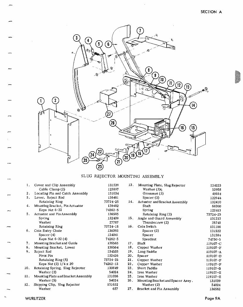
SLUG REJECTOR MOUNTING ASSEMBLY
Cover and Clip Assembly Cable C lamp (2)
Locating Pin and Catch Assembly Lever, Reject Rod
Retaining Ring Mounting Bracket. Pin Actuator
Keps Nut 6-32 Actuator and PinAssembly
Spring Washer Retaining Ring
Coin Entry Chute Spacer (4) Keps Nut 6-32 (4)
MountingBracketand Guide Mounting Bracket, Lower Reject Rod
Pivot Pin Retaining Ring (5) Keps Nut (2) 1/4 x 20
Retaining Spring. Slug Rejector Washer (2)
MountingPlateand Bracket Assembly Washer (5)
Shipping Clip, Slug Rejector Washer
Mounting Plate, Slug Rejector Washer (3)q Grommet (3) Spacer (3)
Actuator and Bracket Assembly Shaft Spr ing Retaining Ring (2)
Angle and Guard Assembly Thumbscrew (2)
Coin Switch Spacer (2) Spacer Speednut
Shaft Copper Washer Long Paddle Space r Copper Washer Copper Washer Short Paddle I ron Washer I ron Washer Mounting BracketandSpacer Assy .
Washer (2) Bracket and Pin Assembly
WURLITZER
SECTION 0
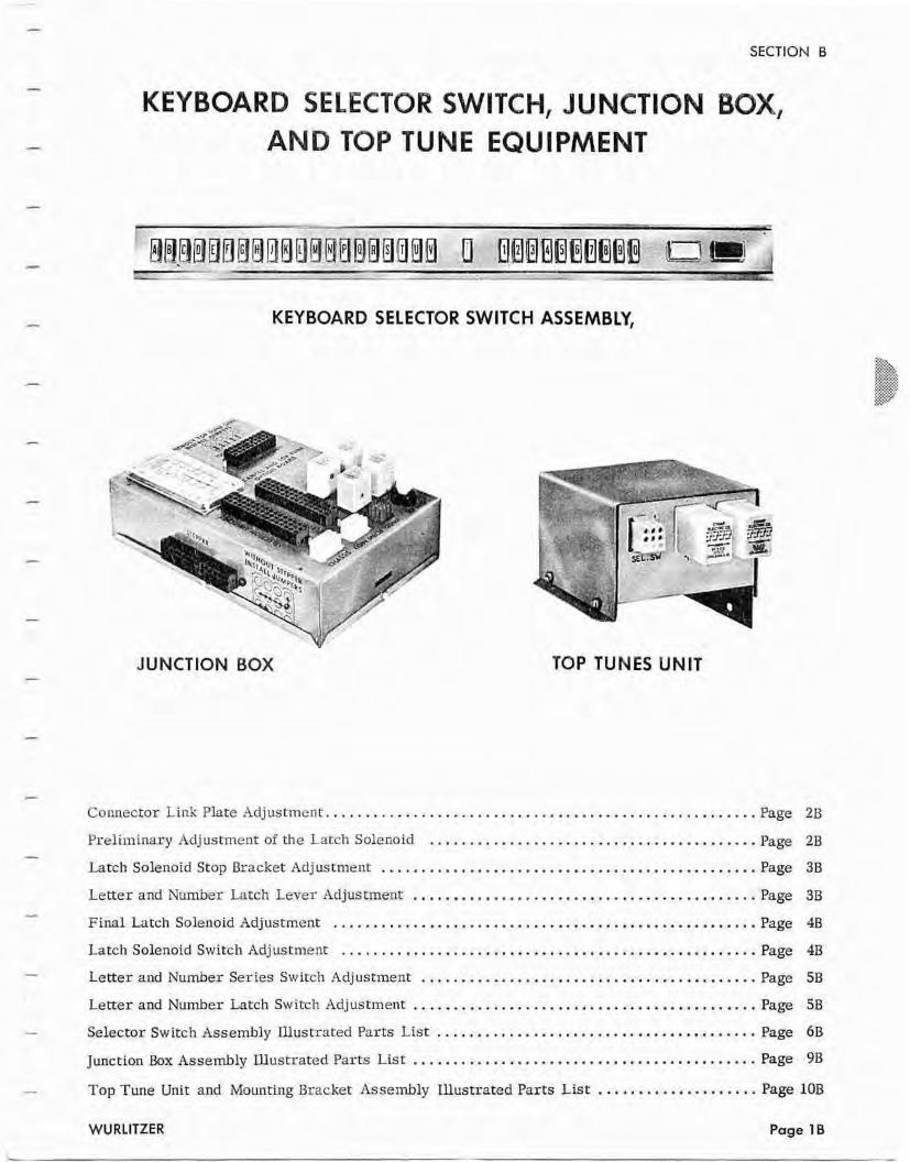
KEYBOARD SELECTOR SWITCH, JUNCTlON BOX, AND TOP TUNE EQUIPMENT
KEYBOARD SELECTOR SWITCH ASSEMBLY,
JUNCTION BOX TOP TUNES UNIT
.................................................... Connector Link Plate Adjustment.. Page 2B
......................................... Preliminary Adjustment of the Latch Solenoid Page 2B
............................................... Latch Solenoid Stop Bracket Adjustment Page 3B
........................................... Letter and Number LatcIl Lever Adjustment Page 3B
..................................................... Final Latch Solenoid Adjustment Page 4B
.................................................... Latch Solenoid Swirch Adjustment Page 4B
.......................................... Letter and Namber Series Switch Adjustment Page 5B
........................................... Letter and Number Latch Switch Adjustment Page 5B
........................................ Selector Switch Assembly Ulustrated Parts Lis t Page 6B
........................................... Junction Bax Assembly mustrated Parrs List Page 9B
.................... Top Tune Unit and Mounting Bracket Assembly mustrated Parts L i s t Page 10B
WURLITZER Page 10
SECTION 8
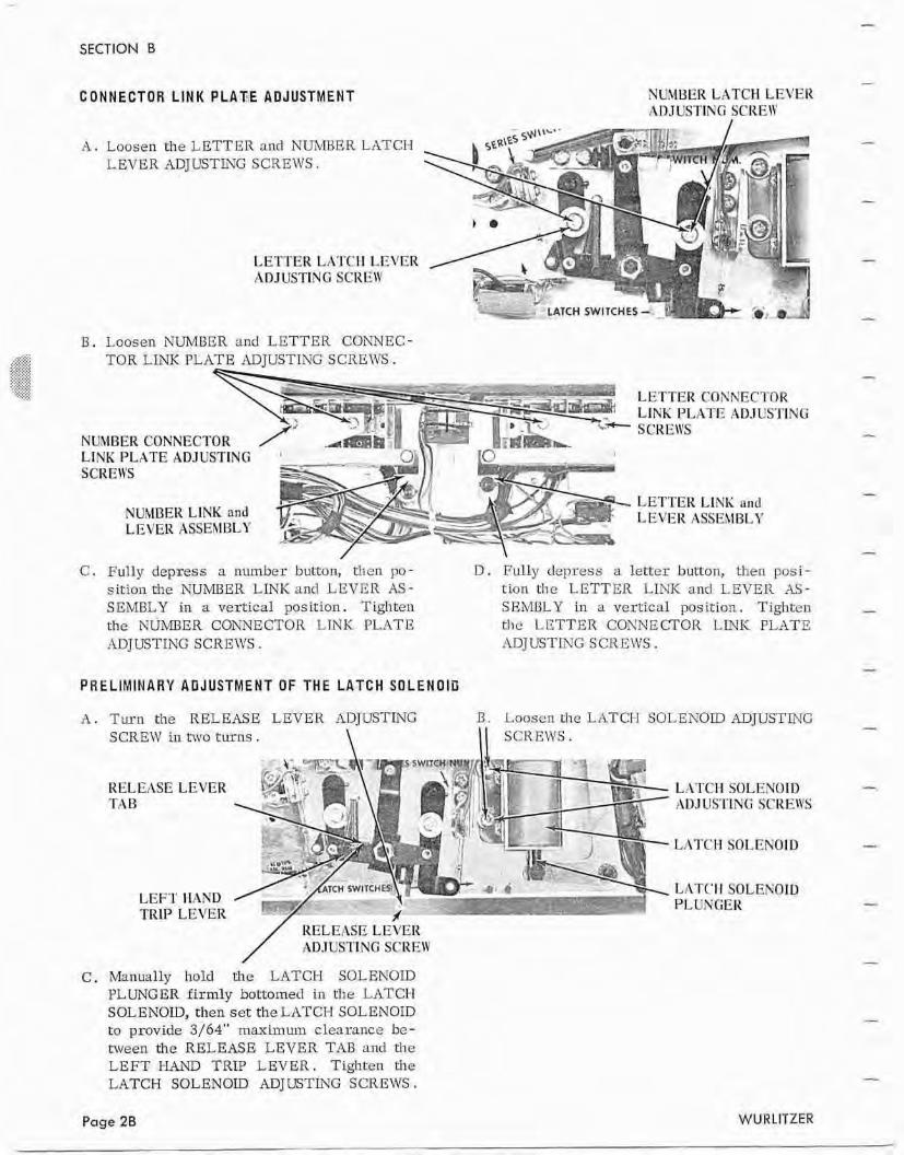
CONNECTOR LINK PLATE ADJUSTMENT NUMBERLATCH LEVER IZDJUSTING SCRE\Y
I
A . Loosen the LETTER and N m E R LATCT-1 LEVER ADJUSTING SCREWS.
LETl'ER LATC-ll LEVER ADJUSTING SCREW
B. Loosen NUMBER and LETTEK CONNEC- /.$T $<.{*
TOR LLiK PLATE ADJUSTING SCREWS. $,<;$:$ :,'<,:.:,X , ':*,y,? .>,+,.:, . , . , LETTERCONNECTOR
. LINK PIATE ADJUSrSING
NUMBER CONNECTOR LINK PLATE ADJUSTING ' S CRE\VS
LETTER LlNK and NUMBER LINK nnd
C. Fully depress a number bunon, then po- D . 17ully dcpress a letter button, then posi- sition the NUMBER LINK and LEVER AS- tion the LETTER LINK ancl LEVER AS- SEUBLY in a vertical position. Tighten SEMULY in a vertical position. Tighten the NUMBER CONNECTOR LJNK PLATE t h e LETTER CONNECTOR LINK PLATE ADJUSTING SCREF47S . ADJUSTPJG SCREWS.
PRELIMINARY ADJUSTMENT OF THE LATCH S O L E N O I U
A . Turn the RELEASE LEVER ADJBTING B . Lnoscn t l ~ c LATCH SOLENOID ADJUS'STNG SCREW in hvo turns. \ KEL E:\SE LEVER TAB
LEFT IlAND TRIP LEVER
/ RELEASE LElrER ADJUST'ING SCREW
C . Manually hold the LATCH SOLEWOTD PLUNGER firmly bottomed in the LATCI-I SOLENOID, then set the LATCH SOLENOID to provide 3/64" maximum clearance be- ttveen the RELEASE LEVER TAB rind the LEFT W V D TRIP LEVER. Tighten the LATCH SOLENOLD ADJLTSTLTG SCREWS,
Page 2B
LATCH SOLENOID ADJUSTING SCREWS
LATCI-1 SOLENOID
A
WUR LlTZER
SECTION B
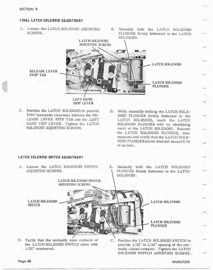
FINAL LATCH SOLENOtO ADJUSTMENT
A . Loosen the LATCH SOLENOID ADJUSTING 13. Manually hold h e LATCH SOLENOID SCREWS. FLUNG ER firmly bottomed in the L,4TCH
SOLENOLD. LhTCIl SOLEKOID ADJUS'TING SCREl\'S \
RELEASE LEVER STOP TAB
LATCH SOLENOID
LATCH SOLENOID PLUNGER
LEFT IlAND l'KIP LEVER
C . Pas ition the LATCH SOLENOID to providc D . While manually holding the LATCH SOLE - 5/64" maximmum clearance between tl~e RE - N O D PLUNGER firmly botromed in the LEASE LEVER STOP TAB and the LEFT LATCH SOLENOID, mark the UTCH HAND TRP LEVER. Tighten che LATCI-I SOLENOLD PLUNGER with an identifying SOLENOD ADJUSTING SCREWS. mark at the LATCH SOLENOID. Keleasc
the LATCH SOLENOID PLUNG RR, then meas urc and verify Chat the LATCH SOLE - N O D PLUNGERtravel does nor exceed3/16 of an inch.
LATCH SOLENOID SWITCH ADJUSTMENT
A . Loosen the UTCI-I SOLENOLD SWITCI-I t3. Manually hold t h e LATCH SOLENOID ADJUSTING SCREWS. \ PLUNGER firmly bottomed in the LATCH
SOLENOID.
LATCI 1 SOLEKOID SWITCH ADJUSTINI; SCIIEIYS \
LATCH SOLENOID LATCH SOLENOID SIVITCII
LATCH SOLENOID PLUNGER
D . Verify rhat the normally open contacts of C . Position the LATCH SOLENOID SWITCH to the LATCH SOLENOID SWITCH close witlt provide 1/32 " t o 1/16 " apening of the nor - 1/32 " overtravel. mally closed contacts . Tighten the LATCH
SOLENOID SWITCH ADTUSTING SCREWS.
Page 4B WURLITZER
SECTION 8
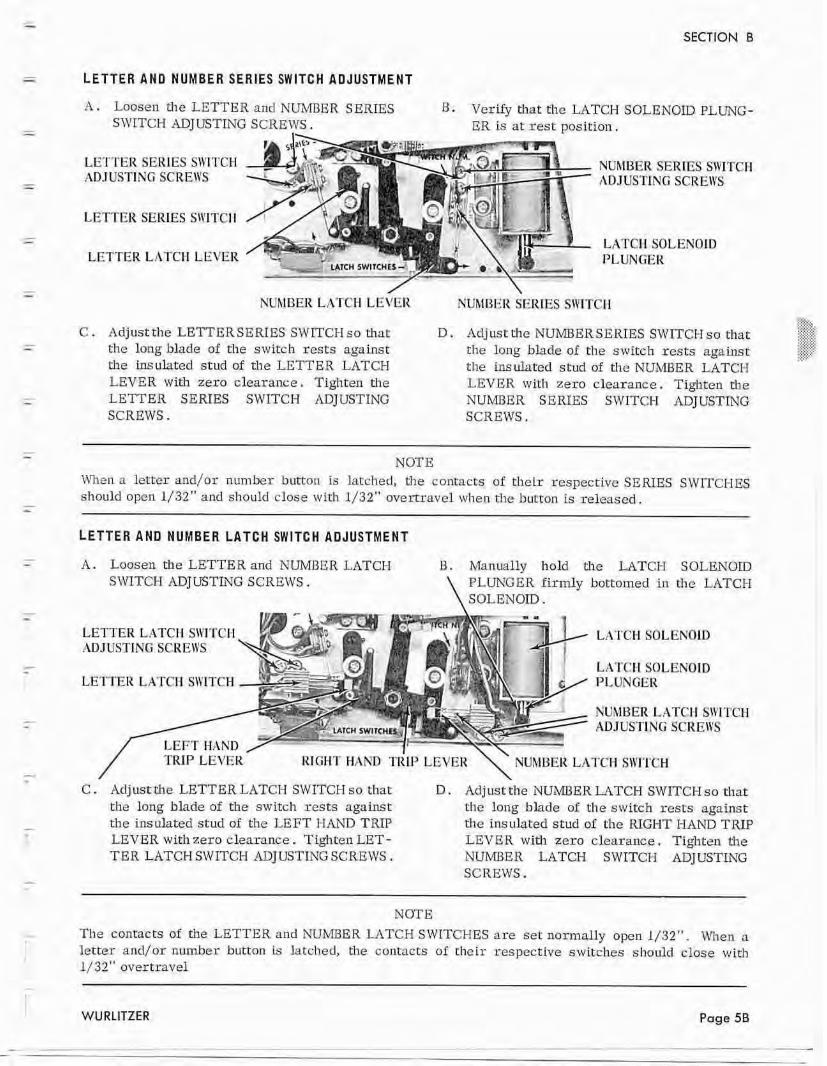
LETTER A N D NUMBER SERIES SWITCH ADJUSTMENT
A . Loosen the LETTER and NUMBER S E R E S B. VcsQ that the LATCH SOLENOID PLUNG- SWITCH ADJUSTZhTG SCREWS. ER is at rest position.
LETTER SERIES SWITCH tZD JUSTING SCREWS
LETTER SERlES SII'ITCI-I
LETTERLATCH LEVER
NUMBER LATCH LEVER NUMBER SERIES SW?TCII
NUhll3ER SERIES SWITCH AD.TUS'TING SCR EII'S
LATCH SOLENOID PLUNGER
I ,. :,x: C . Adjust the LETTERSERIES SWITCI-1 so that D . Adjust tile NUMBERSERIES SWLTCH so that: .. .. r C .. <
the long blade of rl~e switch rests artinst the long blade of the switch rests against -% ... . .
the insulated stud of the LETTER LATCH the ins dated s tud of t he NUhO3ER LATCH LEVER wi th zero clearance. Tighten the LEVER wid1 zero clearance. Tighten the LETTER SERIES SWITCH ADJUSTING NUMBER SERIES SWITCH ADJUSTING SCREWS. SCREWS.
NOTE When a letter and/ar number bitten is latched, the contacts of their respecrive SE EUES SWITCHES should opcn 1/32" and should close with 1/32" overtravel when the button is released.
LETTER AND NUMBER LATCH SWITCH ADJUSTMENT
A. Loosen the LETTER and NUMI3ER LATCH B. Man~rally haId the LATCH SOLENOID SWITCH ADJUSTING SCREWS. \ PLUNGER firmly bottomed in the LATCH
SOLENOID.
LETTER LATCIl SII'ITCM ADJUSTING SCREWS
LETTER LATCI-1 SlVITCH
LATCH SOLENOID
LttTClI SOLENOID PLUNGER
NUMBER LATCI-I Sh'I ADJUST1 NCi SCREWS
C . Adjust rhe LETTER LATCH SWITCH so that D . Adjust the NUMBER LATCH SWITCH so that the long blade of the switch rests against the long blade af tlie switch rests against the insulated stud of the LEFT I-IAh'D TIUP the insulated stud of the RIGHT HAND TRIP LEVER with zero clearance. Tighten LET- LEVER with zero clearance. Tighten the T E R LATCH SWITCH ADJUSTING SCREWS, NUMBER LATCH SIVITCH ADJUSTLNG
SCREWS.
NOTE
The contacts of the LETTER and NUMBER LATCH SWITCHES are set: normally opcn 1/32". When a letter and/or number button is htched, the contacts of the i r respective switches should close wit11 1 J 32" overtravel
WRLITZER Page 5B
SECTION B
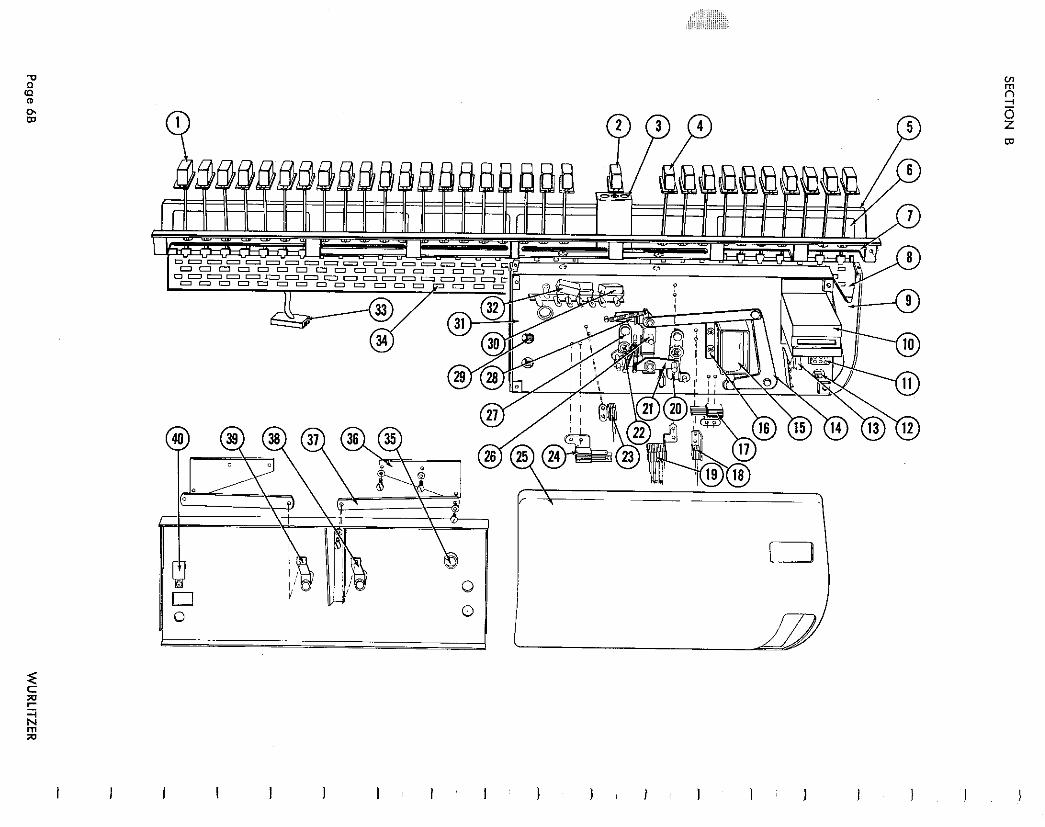
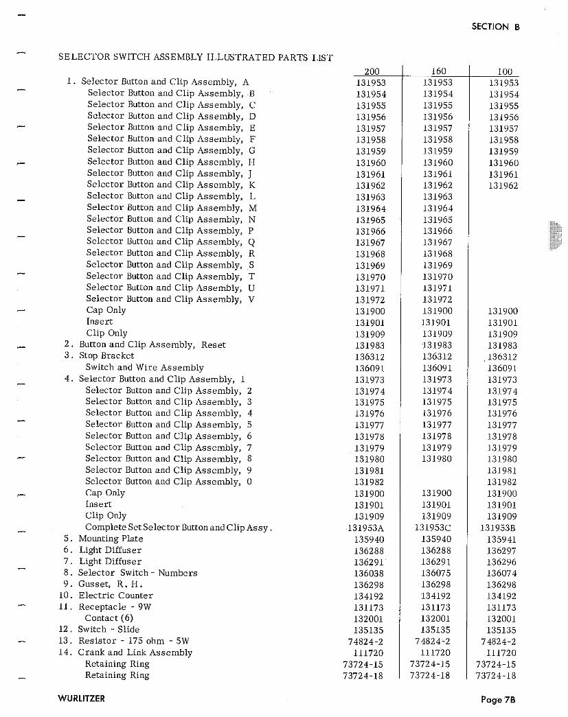
- SELECTOR SWITCH ASSEMBLY ILLUSTRATED PARTS LIST
1. Selector Button and Clip Assembly, A - Selector Button and Clip Assembly, B Selector Button and Clip Assembly, C Selector Button and Clip Assembly, D Selector Button and Clip Assembly, E Selector Button and Clip Assembly, F Selector Button and Clip Assembly, G Selector Button and Clip Assembly, H Selector Button and Clip Assembly, J Selector Button and Clip Assembly, K Selector Button and Clip Assembly, L Selector Button and Clip Assembly, M Selector Button and Clip Assembly, N Selector Button and Clip Assembly, P Selector Button and Clip Assembly, Q Selector Button and Clip Assembly, R Selector Button and Clip Assembly, S Selector Button and Clip Assembly, T Selector Button and Clip Assembly, U Selector Button and Clip Assembly, V Cap Only Inser t Clip Only
2 . Button and Clip Assembly, Reset 3 . Stop Bracket
Switch and Wire Assembly 4 . Selector Button and Clip Assembly, 1
Selector Button and Clip Assembly, 2 Selector Button and Clip Assembly, 3 Selector Button and Clip Assembly, 4 Selector Button and Clip Assembly, 5 Selector Button and Clip Assembly, 6 Selector Button and Clip Assembly, 7 Selector Button and Clip Assembly, 8 Selector Button and Clip Assembly, 9 Selector Button and Clip Assembly, 0 Cap Only Inser t Clip Only Complete Set Selector Buttonand Clip Assy .
5 . Mounting Plate 6 . Light Diffuser
- 7 . Light Diffuser 8 . Selector Switch - Numbers 9 . Gusset, R. H .
10. Electr ic Counter - 11. Receptacle - 9W Contact (6)
12. Switch - Slide - 13. Res is tor - 175 ohm - 5W
14. Crank and Link Assembly Retaining Ring
- Retaining Ring
100 131953 131954 131955 131956 131957 131958 131959 131960 131961 131962
131900 131901 131909 131983 136312 136091 131973 131974 131975 131976 131977 131978 131979 131980 131981 131982 131900 131901 131909
1319538 135941 136297 136296 136074 136298 134192 131173 132001 135135
74824-2 111720
73724-15 73724.18
Page 76
SECTION B
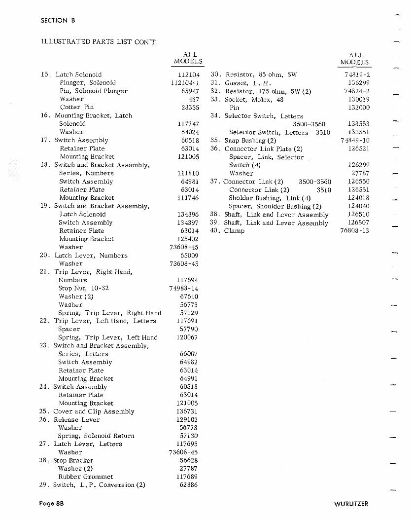
ILLUSTRATED PARTS LIST CON'T
ALL MODELS
1 Latch Solenoid Plunger, Solenoid Pin, Sole~ioid Plunger Washer Cotter Pin
16 . Mounting Bracket, Latch Solenoid Washer
1 7 . Switch Assembly Retainer Plate mounting Bracket
18 . Switch and Bracket Assembly, .. . . . .. . ,.:. .. . .. . . .
Series , Numbers Switch Assembly Retainer Plate Mounting Bracket
19 . Switch and Bracket Assembly, Latch Solenoid Switch Assembly Retainer Plate Mounting Bracket Washer
20. Latch Lever, Numbers Washer
21. Tr ip Lever, Right Hand, Numbers Stop Nut, 10-32 Washer (2) Washer Spring, T r i p Lever, Right Hand
22. T r ip Lever, Left Hand, Letters Spacer Spring, T r ip Lever, Left Hand
23. Switch and Bracket Assembly, Series, Let ters Switch Assembly Retainer Plate Mounting Bracket
24. Switch Assembly Retainer Plate Mounting Bracket
25. Cover and Clip Assembly 26. Release Lever
Washer Spring, Solenoid Return
27. Latch Lever, Letters Washer
28. Stop Bracket Washer (2) Rubber Grommet
29. Switch, L. P. Conversion (2)
30. Resistor, 85 ohm, 5W 31 . Gusset, L. I+. 32 . Resistor, 175 ohm, 5W (2) 33 . Socket, Molex, 48
Pin 34. Selector Switch, Let ters
3500-3560 Selector Switch, Let ters 3510
35. Snap Bushing (2) 36. Connector Link Plate (2)
Spacer, Link, Selector Switch (4) Washer
37. Connector Link (2) 3500-3560 Connector Link (2) 3510 Sholder Bushing, Link (4) Spacer, Shoulder Bushing (2)
38. Shaft, Link and Lever Assembly 39. Shaft, Link and Lever Assembly 40. Clamp
ALL. MODELS
74819 -2 136299
74824-2 130019 132000
133553 133551
74849-10 126521
126299 27787
126550 126551 124018 124040 126510 126507
76808-13
WURLITZER
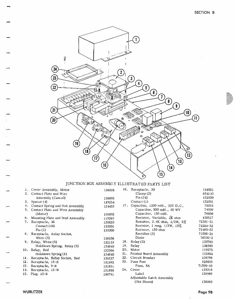
SECTION B
JUNCTION BOX ASSEMBLY ILLUSTRATED PARTS LIST - I . Cover Assembly, Motor 136898 16 . Receptacle, 30 2 . Contact Plate and Wire Clamp (2)
Assembly (Cancel) 136895 Pin (24) 3 . Spacer (4) 119254 Contact (1) - 4 . Contact Spring and Hub Assembly 124453 17 . Capacitor, 1200 mfd., 35V D.C. 5 . Contact Plate and Wire Assembly Capacitor, 500 mfd ., 50 WV
(Motor) 136892 Capacitor, 150 mfd. 6 . Mounting Plate and Stud Assembly 119267 Resis tor , Variable, IIK ohm - 7 . Receptacle, 48 130020 Resis tor , 2 .4K ohm, 1/2W, 5%
Contact (44) 132001 Resis tor , 1 meg, 1/2W, 10% Pin (1) 132000 Resis tor , 150 ohm
8 . Receptacle, Relay Socket, Rectifier (3) - White (5) 136336 Diode 9 . Relay, White (5) 122133 18 . Relay (2)
Holddown Spring, Relay (5) 134840 1 9 . Relay 10 . Relay, Red 122366 20. Motor
?.-
Holddown Spring ( I ) 134840 21 . Printed Board Assembly 11. Receptacle, Relay Socket, Red 136337 22. Circui t Breaker 12 . Receptacle, 15-R 131892 23 . Fuse Post
- 13 . Receptacle, 9-R 131931 Fuse, 8A 14 . Receptacle, 15-W 131888 24. Cover 15 . Plug, 12-8 136791 Label
Adjustable Latch Assembly - (Not Shown)
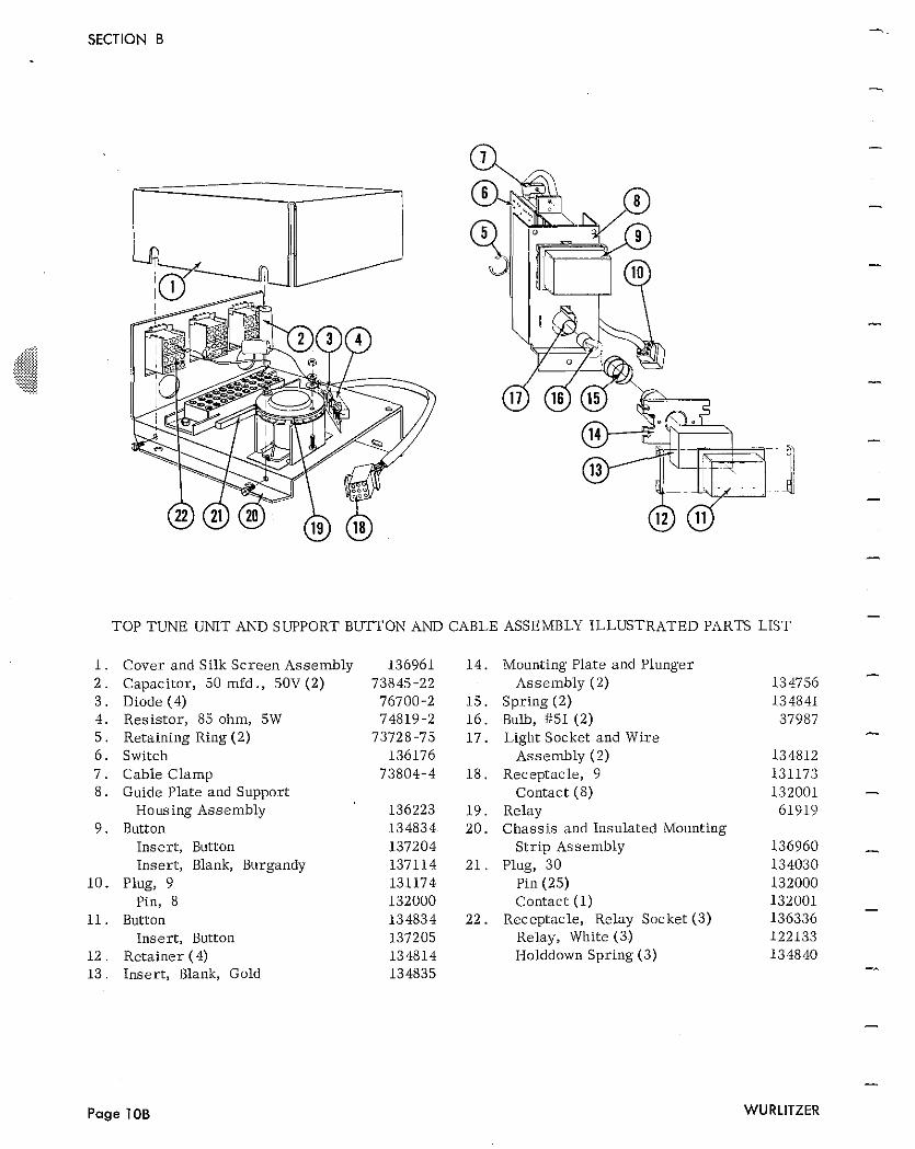
TOP TUNE UNIT AND S WPORT BUTTON AND CABLE ASSEMBLY ILLUSTRATED PARTS LIST
Cover and Silk Sc r een Assembly Capaci tor , 50 mfd ., 50V (2) Diode (4) Resis tor , 85 ohm, 5W Retaining Ring (2) Switch Cable Clamp Guide Plate and Support
Housing Assembly Button
Inser t , Button Inser t , Blank, Burgandy
Plug, 9 Pin, 8
Button Inser t , Button
Retainer (4) Inser t , Blank, Gold
Mounting Plate and Plunger Assembly (2)
Spring (2) Bulb, #51 (2) Light Socket and Wire
Assembly (2) Receptacle, 9
Contact (8) Relay Chass i s and Insulated Mounting
S t r ip Assembly Plug, 30
Pin (25) Contact (1)
Receptacle, Relay Socket (3) Relay, White (3) Holddow~l Spring (3)
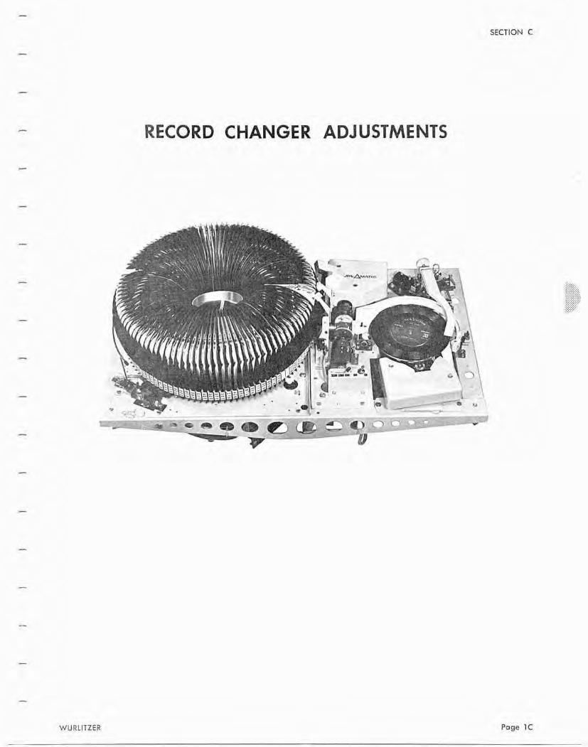
SECTION C
RECORD CHANGER ADJUSTMENTS
WURLITZER Puge 1 C
SECTION C
INDEX T O ADJUSTMENTS
......................................... Selection Accumulator Adjustment Page 4C
Shaft and Magnet A r m Assembly Adjustment ................................ Page 4C
............................................ Overr ide Assembly Adjustment Page 5C
......................................... Magazine Lock Switch Adjustment Page 7C
......................................... Magazine Dr ive Motor Adjustment Page 7C
Digital Record Now Playing Indicator Adjustment ............................ Page 8C
......................................... Side 1 Cancel Solenoid Adjustment Page 8C
.................................... Side 1 and 2 Readout switch Adjustment. Page 9C
................................................. Safety Switch Adjustment Page 11C
Bail and Bushing Assembly Clearance Adjustment ........................... Page 11C
........................................ Main C a m Motor Brake Adjustment Page 11C
.............................................. Trans f e r Switch Adjustment Page 12C
................................................ Cancel Switch Adjustment Page 13C
........................................... Record Takeout A r m Alignment Page 13C
....................................... Playmeter Reset Magnet Adjustment Page 13C
................................................... Side 1 Shift Adjustment Page 14C
........................................ T u r n A r m Holdout C a m Adjustment Page 15C
..................................... Record Takeout A r m Turn Adjustment Page 15C
...................................... Record Takeout A r m Stop Adjustment Page 16C
......................................... Turntable Drive Wheel Adjustment Page 16C
....................................... Turntable Speed Change Adjustment Page 17C
................................................ Tone A r m Lift Adjustment Page 18C
.................................................. Stylus Brush Adjustment Page 18C
............................................. Tone A r m Release Adjustment Page 19C
............................. Tone A r m Feed-In and T r i p Switch Adjustment Page 19C
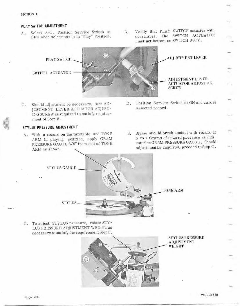
................................................... Play Switch Adjustment Page 20C
............................................... Stylus P r e s s u r e Adjustment Page 20C
.......................................... Turntable Pilot Reset Adjustment Page 21C
.................................................. Safety Ci rcu t Adjustment Page 21C
'1-
SECTION C
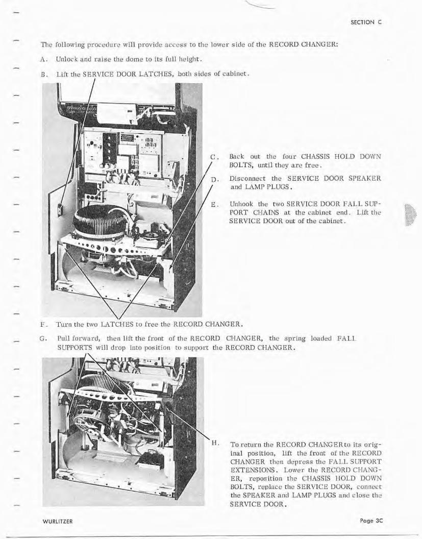
The lollowlng proccdurc will provide access t o d ~ e lower sicle of the RECORD CHANGER:
11. Unlock and raise the dome to its l u l l lieigl~t.
I3 . LLFt ~ h e SERVICE DOOR LATCHES, both sides of cabincr .
k c k out the four CHASSIS HOLD DOWN BOLTS, unti l they are f ree .
, Disconnect the SERVICE DOOR SPEAKER and L I M P PLUGS.
E . Unhook the twoSERVICEDOORFALLSUT- PORT CI-IATNS at the cabinet end . Lift t h e S E RVICB DOOR nut of the cabinet .
F. T u r n the rwo LAT~I-TES t o free the RECORD ChLi iGER.
- G . P u l l Inr\vard, then l ift the front: of tlie RECORD CI-EANGER, the spring loaded FALL SUPPORTS w i l l d rop intu position to supporr the RECORD CIHANGER.
To r e r u n the RECORD CHAXGERro i ~ s arig- inal position, Llfi the f m u t o f t h e RECORD CHANGER t h e n depress the FALL. S LIPPORT EXTENSIONS. Lower the RECORD CI-IANG - ER, reposition the CflASSTS I-IOLD DOWN I30LTS, rcplace rlle SERVICE DOOR, connect the SPEAKER and LAMP PLUGS and c lose the SERVICE DOOR.
WURLISZER Page 3C
SECTION C
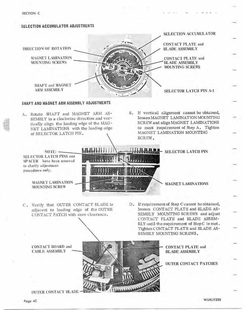
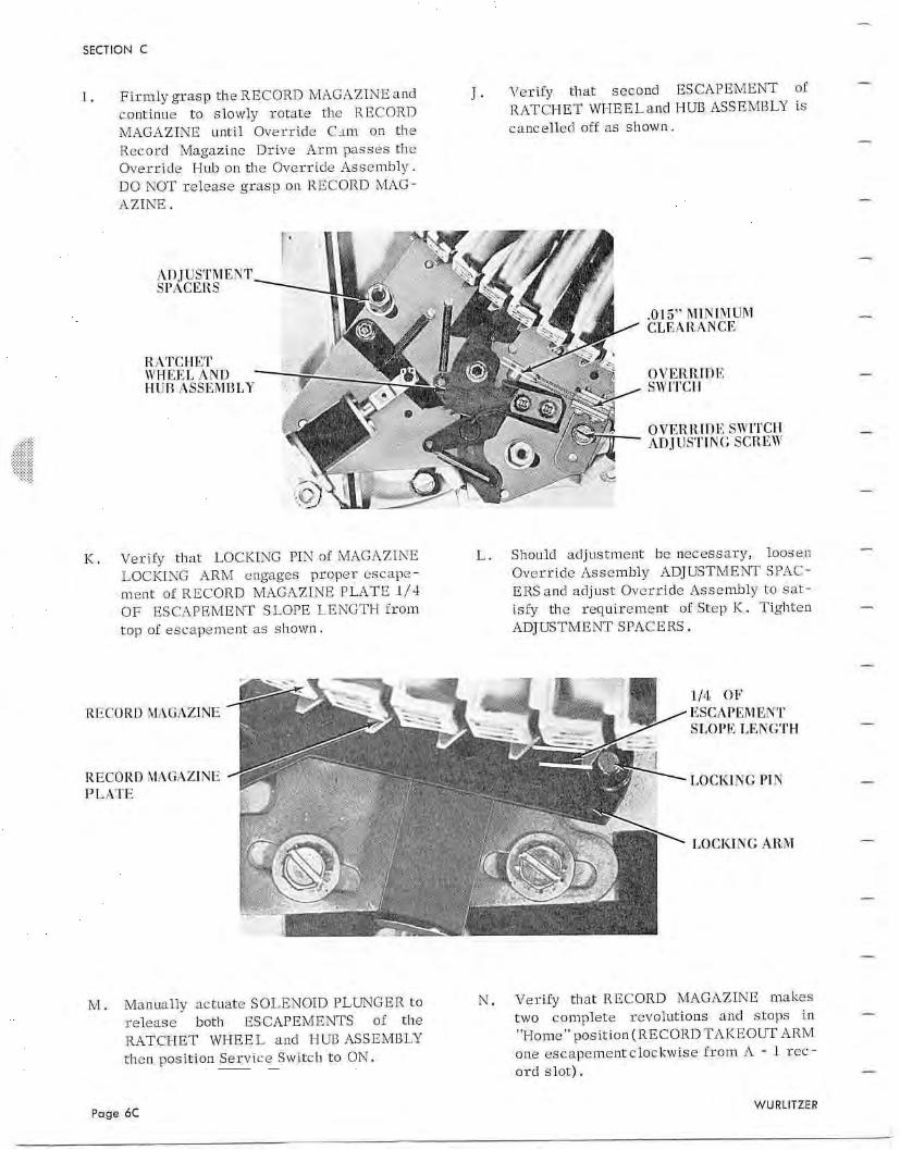
OVERRIDE ASSEMBLY ADJUSTMENTS
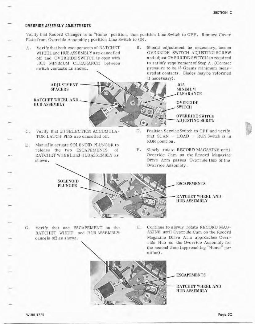
Ver i fy that Record Changer is i n "Hoare" position, Lhcn pasition Line Switch to OFF. Remove Cover Plate f rom Override Assembly; position Line Switch t o O N ,
A . Vcr* that both escapements a1 RATCHET R . Should adjustment be necessary, loosen WHREL and FTUB ASSEMBLY are ctincelled OVERRJDE SwITClH ADJUSTTNG SCREW off and DVERRDE SWTTFH is open with and ad jus t OTrEK RIDE SWrTfCH as required .015 MhXMUM CLEARANCE between to satisfy requi-cement of Step A . (Contact switch contacts ss shown. pressurc to be 15 G r a m s minimum meas -
\ ured at contacts . Blades may br rc inrmed if necessary) .
AD JUSTRl ENT SI'ACKRS
-0 15 h1INTMUM
m CLEARANCE
OY ERRlUE SW1TCI-I ALIJCTSTING SCREW
C . Verify thar all SELECTION ACCUMULA- D . Position Service Switch to OFF and verify TOR LATCH PINS are cancelled off. chat SCAN - LOAD - RCTNSwitch is i n
RUN positlon . Manually actuate SOLENOID PLUNF E R to release the two ESCrlPEMEhTS of P . Slowly rotate RECORD MAGAZINE until RATCHETUrHEELand HIJI3ASSI<hdHLY as Qvcrride Cam on rhe Record Magazine shown. Drive Arm passes Override Hub of the
Overr ide As sernbly .
ESCAPEMENTS
RATCHET WHEEL ANI) rrun ASSRMRT~Y
G. VcrLfy that one ESCAPEMENT on t h e 1-1. Continue to slowly rotate RECORD MAG- RATCHET WHEEL and HUB ASSEMBLY AZINR uricil Override Cam on the Kccord cancels off as sliown. M n g a z i ~ ~ e Drive Arm approaches Over -
\ r i d e Hub on the Override Assembly f o r tlie second t ime (approaching "Hornel>~o- sit ion).
ESCAPEMENTS
I-lATCHET \YHF:EL AND ITUD ASSEMBLY
WURLlTZEB Page 5C
SECTION C
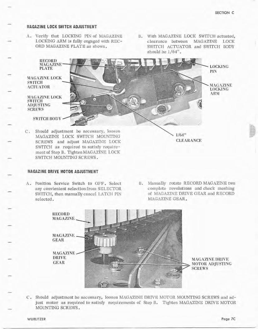
MAGAZINE LOCK SWITCH ADJUSTMENT
A. Verify that- LOCKING PIN of MAGAZINE U. With MAGAZINE LOCK SMrlTC13 actuated, LOCKING ARM i s fully engdged with REC- clearnncc bctwecn MAGAZINE LOCK ORD MAGAZINE PLATE as sl1otvn. SWITCI-I ACTUATOR and SWITCI-I BODY
shuulcl be 1/64".
--;-, T/s 'T- *TIk , .4 PIAArrE 1 '.-I
bI:\G 4XTY E LOCK \4 S1llITC1l I.- '%
. . ACT tT.+\TT)R
\
.r' I - . * >
hlACZllVFiLOCI< S\ l l IT~ l I 9
I ~ S ~ I ~ I I G 141 SCREW5
.<
>" -- ' \ SIVI'FCH I3C)I>Y flCb< -
. ."&+
C . Should adjustincrr~ be necessary, loosen hhiGAzIr\T LOCK SWITCH MOUNTING \ 1/fi4'~
SCREWS and a d j u s t MAGAZKE LOCK CLEA ItANCI; SIVITCH as required to sarisfy requirc- ment of Step B. Tighten hrL4GAXINE LOCK SWITCH MOUXTtNG SCREMrS.
MAGAZINE DRIVE MOTOR ADJUSTMENT
A . Position SclPice Switch t o OFF. Select D . ~lZanually rotate RECORD MAG hZThTE two any convienient selection f rom SELECTOR cnmplete revol~rtions and check meshing SL171TCN, then manually cancel LATCFI PIN of k I A G X Z I N E DRIVE GEAR and RECOKU selected. WIG-1ZIN E G EAR.
RECORD MAGAZINE
Rlhl;A7;1UE TIT1IVE RIOfTOK AD3 US'I ' ING SCK EII'P
C . Should adjustment be necessary, loosen MAGrlZINE DRIVE MOTOR MOUNTING SCREWS and nd- just motor as required to satisfy requirements of Step B. Tigl~ten h4,'IGAZTNF: DRIVE MOTOR MOUNTING SCRIZWS .
WURLlTZER Page 7C
SECTION c
..... ,-.:::: . . . , , , ,
.:::...:: , . . , , , , . . , . . . , , . . . . ,,..
,,,, - ,,,. - I::.::'::: .. . . -, - , . , . . , , , ..,,, .. ,
-- , , ,,
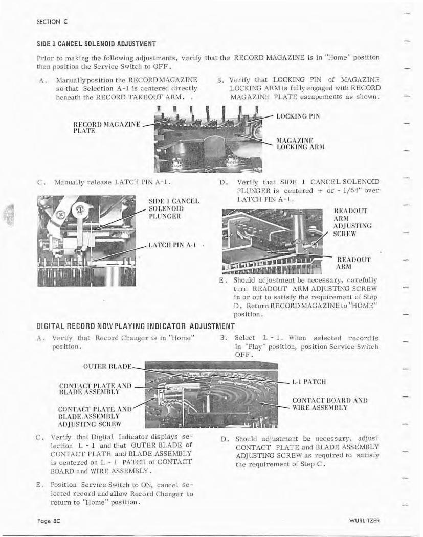
SIDE 1 CANCEL SOLENOID AUJUSTMENT
Pr ior to making the f d l o w i l ~ g ad.iustments, verify that: t11e RECORD M4GAZINE is i n "Home" position then position rhe Service Switc1.1 to OFF.
A. Mmual ly po9 Ition he RECORD MAGAXTNE 13, VcrifIJ that LOCKIhTG PIN of MAGAZLhTE so that SeZectien A - 1 is centcrecl dircctly LOCKING ARM is fully engaged wit11 RECORD bcneath tlic RECORD TAKEOUT A R M . . MAGAZINE PLATE escapements as shown.
LOCKING PIT
C . Manulillv release IATCH P I N A - 1 . D . VcrLfy that SIDE 1 CAXCE L SOLENOID PLUNGER Is centered I- o r - 1 J64" over LITCFI PIN A -1 .
E . Slioulcl ~tr l j~~ncn-rent he ncuessarg, carefully t u r n LZIIADULT ARM ADJUSTWG SCREW i n or out to sat isfy the requiremerlt of Stcp D. Kcturn RECORD W1GAZIN !I t o 'NOME" pus it ion .
Dl GITAL RECORD NOW PLAYING INDl CATQR ADJUSTMENT
.5,. Verily that Record Changcr is in "Hamc" B. S~lc r t : L - 1 . W h e ~ i selected rectrrrl i s position. in "Play" position, position Service Switch
OFF.
7 % . . --
, . L-I PATCH
. ,
CONTACT l lOA 4AU CONTACT PIAhm AND WIRE .46SFdJ1F31,Y T3T,A1)E,.ASt;En"lllLY AT) JVSTTXG SCREIV
C . Verify char Digital Indicator cl is plays sc - D . Should adjustment be necessary, adjust lection L - 1 ancl that OUTER BLADE of CONTACT PLATE and l3L"LDR hSSEM13L17 COSTACT PLATE and BLADE ASSEMBLY ADJUSTING SCREW as required tn satisfy is cerltcred an L - 1 PATCH of COYTACT the requiremenr of Step C . IIOARD nncl WIRE ASSEMBLY.
E . Pus i t inn Service Switch to ON, canccl sc- lectecl rcc osd and bow Record Changer t o
r e tu rn to "Home"' position.
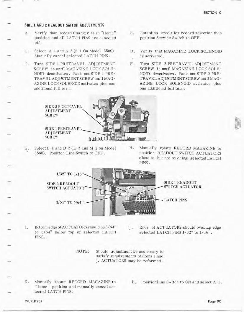
SIDE 1 ANU 2 READOUT SWITCH ADJUSTMENTS
A . Ver i fy that Record Changer is i n "Holnc" position and ell LATCI-I PIhTS arc cancclcrl off .
C. Select A-1 and A-2 (13-1 On Modr l 3ShO). Manually cancel selected W T C H PINS,
E Tu rn SIDE 1 FRBTRhVEL ADJUSTMENT SCREW i n mtil MAGAZINE LOCK SOLE- N O D deactivates . Back out SLDE 1 PRE- T M V E L ADJ USTM ElYT S C R EZV unt i l MAG - AZINE LOCK SOLENOIU activates plus one additional f u l l t u r n .
13. Establish credit f o r record selectiarr then position Service Switch t o OFF.
SIIIE 2 PEETI1 .A DJt?STJlT;,NT SCR Em'
SIDE 1 PRKTII AL)J US'rhl EN'I' SCIZ En'
AVEL
AVKL
D. Verify that MAGAZINE LOCKSOLENOID is ~ ~ c t i v a t e d .
G . Se lec tD-1 and D-2 (L-2 and M-2 on Moclel H. Manually rotate RECORD M.4GAZINB to - 3560). Position Line Stvitch t o OFF. position READOClT SWITCI-I ACTUATORS
close To, but nor touching, selected LATCH PTKS .
F . Turn SIDE 2 PRETRAIrEL ADJ USTMRNT SCREW in until MAGAZINE LOCK SOLE - NOID deactivates. Back our SIDE 2 PRE - TRAVEL ADJUSTMEAT SCREW unclI MAG - AZINE LOCK SOLENOID activates plus onc addirional rull t u r n .
IATCM PINS
1. Dotrem edge oiACTUATORS should be 3/64" J . Ends oi ACTUATORS should overlap edge t a 5/64'' below top of selectecl LATCI-T selected LATCH PINS 1/32'"to 1/16". PINS.
NOTE: Shoulrl ad jus t~ncnt be necessary to satisfy tcquirernents af Steps I and J , JZCTUATORS may he reformed.
K . Manually rotace RECORD MAGAZINE to L. PusitionLine Switch ro ON and select A-I . "Home" position and raanurrlly ca~ lcc l se- lected LATCH PTNS .
SECTION C
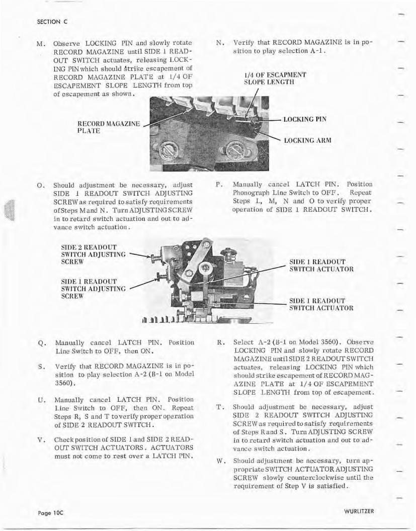
M. Observe LOCKING PIN and slowly rotate N. Verify that RECOKD W G A Z I N E is in po- w
RECORD MAGAZINE until SIDE 1 READ- sition to play selection A-1 . OUT SWITCH actuates, r e l e a s i n g L,OCK - LNG PTN which should Strikc escapement of RECORD MAGAZINE PLATE a t 1/4 O F ESCAPEMENT SLOPE LENGTH from top of escapement as s h o w n ,
RECORD hli1GAZlNE PLATE
114. OF ESC.4PMENT S1,OI'L LENGTH
LOCKING PIN
LOCKTNC AHM
0 . Should adjustment, be necessary, adjust I?. Manually cancel LATCI-I FIN. Posicion SIDE 1 READOUT SWITCH Ai3JUSTING Phonograph Line Switc1.r t o OPT:. Repeat SCREW as required t o sat isfy requirements Steps L, M, N and 0 t o verify proper - of Steps M and N . Turn AD] USTING SCREW operatian of STDrE 1 READOUT SWITCH. i n to retard switch actuation a n d out t o ad- vance switch actuation.
SIDE 2 RF,AI)OUT SWITCH ADJUSTING SCREW
SIDE 1 READOUT SWITCH :ID JUSTTNC SCREW
STTIE 1 READOUT SWITCH ACTUlITOR
SLOE I KEAROUT SWITCH ACTUATOR
Q. Manually cancel LATCH PIN. Position Liae Switcl l to OFF, then ON.
S. Verify that: RECORD MAGAZIm is in po- sition to pIzy selection A-2 (B-1 on Model 3560).
U. Manually cancel LATCH FIN. Position Line Switch t o OFF, then ON. Repeat: Steps R, S a n d T toverify proper operation of SIDE 2 READOUT SWITCH.
V . CheckpositionofSIDE 1 a n d S I D E 2READ- OUT SWITCH ACTUATORS. ACTUATORS must not came to rest over a LATCH PIN.
R , Select A-2 (I3-1 on Model 3560). Ohserve LOCKING PIN and slowly rotate RECORD MAGAZINE uli t i l SIDE 2 READOUT SWITCI-I ac tuaces , releasing LOCKLUG PIX wl-i ic h should strike escapement of RECORD MAG - AZINI? PLATE at 114 OF ESCAE'EMEhT SLOPE LENGTI-I from top of escapement.
T . Should adjusrrncnt be necessary, adjust: SIDE 2 READOUT SW'ITCH ADJUSTING SC R I? W as 1:equircd to satisfy rrcquirements 01 Steps Rand S . Turn ADJUSTING SCREW in t o retard switch adtlllation and out to ad- V a l l F c switch acl-uarion .
W . Shouldad jus tment be necessary, turnap- propriate SWITCH ACTUATOR ADJUSTING SCREllr slowly counterclockwise until the requirement of Step V is sarisf ied .
Page 1 OC WURCITZER
SECTION C
SAFETY SWITCH AlJJUSTMENT
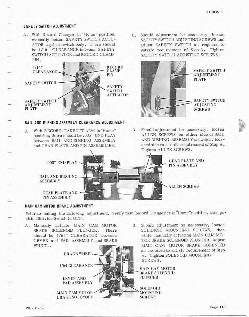
A . W it11 Record Changer in "Flome" position, B. Sliulould adjustment be necessary, loosen man~~ally bottom SAFETY SWITCH ACTU- SAFETSISWITCFI ADJUSTING SCREWS and ATOR against switch body. There should adjust SAFETY SWITCI-I as required t o be 1/16 " CLEARANCE betwecn SAFETY satisfy recluirement of Step A. Tighten SWITCI-I ACTUATOR ancl RECORD CLAMP S M E T Y SWITCT-I ADjUSTLVG SCREFVS. PTN.
1/16" CLEARA
SAFETY Sn'lTCII h1)JUSTRII;;KT PLATE
RECORD CLAAlP 1'1 N
Shl:ETI' S~'1TCII ncrruxrolt
BAIL AND BUSHING ASSEMHLY CLEARANCE AOJUSTMENT
A. With RECORD TAKEOUT ARM in "Home" 13 . position, these should be .005" END PLAY bemeen RAIL lII\13 BUSHING ASSEMBLY and GEAR PLATE Ah33 PIN ASSEMBLIES.
\
-005'' END P1,AY
BAIL AND BUSHIE(; ASSE31ULY
GEAR PLATE AND PIN ASSEFIRLY
SAFETY SWITCH ,An JIISI'MEYT I'LATE
SAFETY SWITCH AnJ USSING SCREWS
>..:. > O.+.>.
..".+.> ),:.:?#:> ::,:?.:<?'
Slleulrl adjustment be necessary, loosen ",...,..
,-.;.:,..L :t ...,,- .,,:
ALLEN SCREWS on either side of RAIL JZAD BUSHING ASSEMBLY mdadjust loas- ened side to satisfy requirement of Step A. Tig j~ten ALLEN SCREWS.
GEAR PI,ATE AYD PIN ASSEMBLY
ALLEN SCREWS
MAIN CAM MOTOR BRAKE ADJUSTMENT
Prior to making tl1e following adjustment, verjfy tlrat Record Changer is i n"1-Iome"position, then PO- sirion Service Switch ra OFF.
,4. Manually actuate MAf;Rf CAM MOTOR D. Should adjustment be necessary, loosen BRAKE SOLENOID PLUNGER . There SOLENOID MOUNTING SCREWS, then shoc~ld be 1/64" CLEllRANCE between while m,mually actuating MAIN CAM MO- LEVER and PAD ASSEMnL'L' and BRAKE TOR BRAICE SOLENOID PLUKGER, adjust WHEEL.
LEVER A N I1 I'AR StSSER113LY
h1AI.N Chhl MOTOR BRAKE SOLI<NOtI)
MAIN CAM MOTOR BRAKE SOL as required t o satisw requirement A . Tighten SOLENOID MOUXTING SCREWS.
R I P ~ I Y cAni MOTOIE BIWKE SO1,ENOIU I'LUKGKR
S O I , F ~ ~ O I C) \IOUNTlKG SCKE,I'IIS
WU RLITZER Page 11C
SECTION C
TRANSFER SWITCH ADJUSTMENT
Verify that a record is in "Playw position. Cancel rccord and immediately upon record entering REC- ORD MAGAZINE, posirion Service Switoll ED OFF.
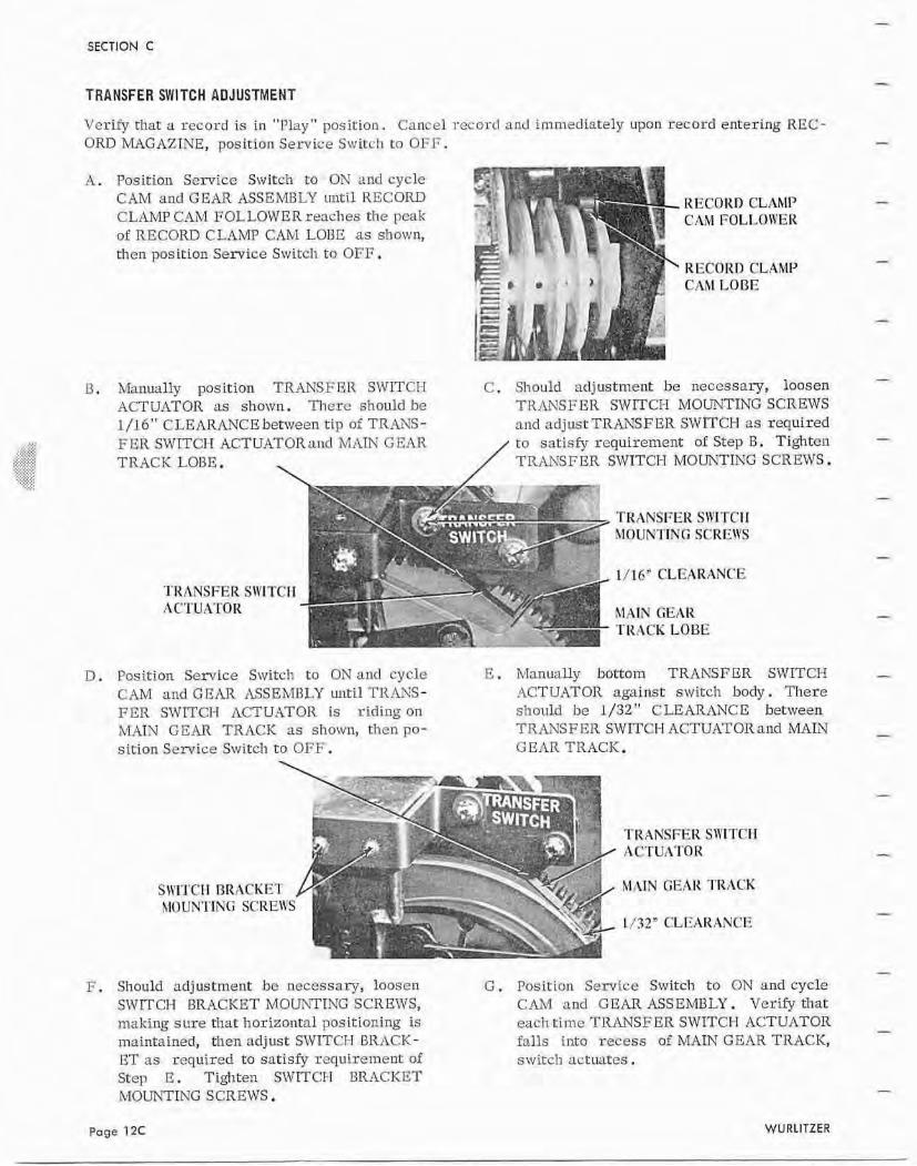
A . Position Service Switch to ON and cycle CAM and GEAR ASSEMBLY ~ m t i l RECORD RECORD CLAMP CLhMP CAM FOLLOWER renclles the peak CAM FOLLOlYEK of RECORE CLAMP CAM LOBE as shown, thcn position Service Switch to OFF.
RECORD CLAhP CAM LODE
Mallually position TRANSFER SWITCH C . S11 ould adjustment be necessary, lonsen ACTUATOR as shown. Tlicre should be TRfiTSPER SWITm-I MOUT\XING SCREWS 1/16'' CLEARANCE betmeen t ip of TRANS- and adjust TRANSF ER SWITCH as required F E R SWITCI-I ACTUATORand MAIN GEAR t o satisfy requirement of Step I3 . Tighten TRACK LOBE. TRANSFER SWITCH MOWTINC SCREWS.
: I J I F " CLEARANCE TRANSFER SW'ITCII 4 C'I'U A'I'O R
TRACK LOBE
D . Position Service Switch t o Oh' and cycle E. Manually bottom TRANSFER SWITCH CAh4 and GEAR ASSEMBLY until TRANS- ACTUATOR against switch body. There FER SWITCH ACTUATOR is riding on should h e 1 /32 " CLEARANCE between MAIN GEAR TRACK as shown, thcn pa- TRANSFER SWITCH ACTUATORand RUIN sition Service Switcl~ t o OFF. GEAR TRACK.
'KET ::RE\\
TRANSFER SWTCI I A GTW!t'I'OR
1132" CLEARANCE
F. Should adjustment he necessary, loosen G . Position Sewfce Switch to ON and cycle SMrITCIJ BRACKET MOUNTING SCREWS, CAM and GEAR ASSEMBLY. Verify that making sure that: horizontal positioning is each time TRANSFER SWITCH ACTUrtTOR maintained, then adjust SFVITCH BRACK- falls into recess af MAIN GEAR TRACK, ET as required to sat isfy requirement of srvirch actuates. S t q E . Tighten SWITCI-I BRACKET MOUNTING SCREWS.
Page 12C WURLITZER
- SECTION C
- CANCEL SWITCH ADJUSmENT
Prior to making the following adjustment, position SERVICE SWITCH t o OFF ancl ver- that SCAN-
- LOAD-RUN SWITC1.T is in RLN position, Make a record selection.
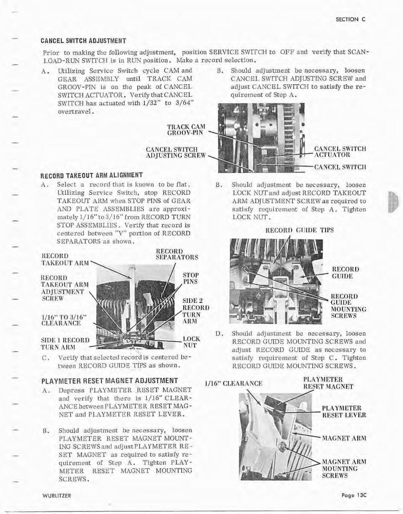
A . Utilizing Service Switch cycle CAM and Should adjustment be izecessary, loosen GEAR ASSEMBLY until TRACK CAM CANCEL SWTTCI-I ADJUSTING SCREW and GROOV-PIN is o n the peak of CANCEL adjust CANCEL SWITCI-1 t o satisfy the re- SWITCH rlCTUATOR. Verify that CANCEL quircrnent of Step A. SWJTCT-I has actuated with l)32" t o 3/64" ovenravel.
TRACIC CAM T,ROOV-1'1 N
CANCEL SIVITCH .A1 IJUSTING SCREW
RECORD TAKEOUT ARM ALIGNMENT
CANCE1, SWITCH ACTU ATlER
CANCEL STITCH
A . Select: a recorcl that is known t o be flat. B. Should adj ustme~lt be necessary, l ~ o s e n - Uttlizing Service Switch, stop RECORD LOCK NUTand ad jus t RECORD TAKEOUT P Y ~ FA>,
TAKEOUT ARM when STOP PINS of G E A R ARV ADJUSTMENT SCREW as required to ..> > > ., .; C "
> ,>
AN13 PLATE ASSEMBLIES are approxi- satisfy requirement of Step A . Tighten <';: . .
- mately 1/16'' to 3/16" from RECORD TURN LOCK NUT. STOP +ISSGMBLIES. Verify rllat record is centered between "V" portion of RECORD RECORI) GllIDE TIPS
SEP14RATDRS as shown.
KECORD RECORD SBPARATORS
TYNEOUT AKRl / TtECOrtlI STOP TAKEOUT ARM M I S
SIDE 2 RF,COR 'l'lSR,?4
CLLAR.ANCK hR3I
SlDE I KRCDR. LOCK TCTILN .klt$l NUT
RECORD GTJlT)E
Should adjustment bc necessary, loosen RECORD GULI3E MOUhTING SCREWS a n d adjust RECORD GUIDE as lreccssary to
C , Verify rhat selzcterl record is centered be - satisfy requirement nf Step C . Tighten tween RECORD GLTIDE TIPS as shown. IEECOKD GLKDE MOUhTING SCREWS.
- PLAYMETER RESET MAGNET ADJUSTMENT 11'16" CLEARANW, PT.AYRIETER
A . Depress PLAYMETER .RESET MAGNET RESET ill I ~ G Y E T
and verify that there is 1/16" CLEAR- - ANCE between FLAYMETER RESET MAG- & Ph AYhIETER NET ancl PLAYMETE R RESET LEVER. - -,:, .. , RESET LEVER
0 . Should adjustment be necessaly, loosen IyLAYMBTER RESET MAGNET MOUNT- mTG SCREWS and ndjustPLAYMETER RE-
- SET MAGNET as required to satisfy re- quirement: nf Step A . Tiglrten P W Y - METER RESET MAGNET MOUSTING
- SCREWS.
JIAGNET ARM
MAGh'ET ARM ivl0UNfl'lNG SCREWS
WURllTZER Page 13t
SECTION C
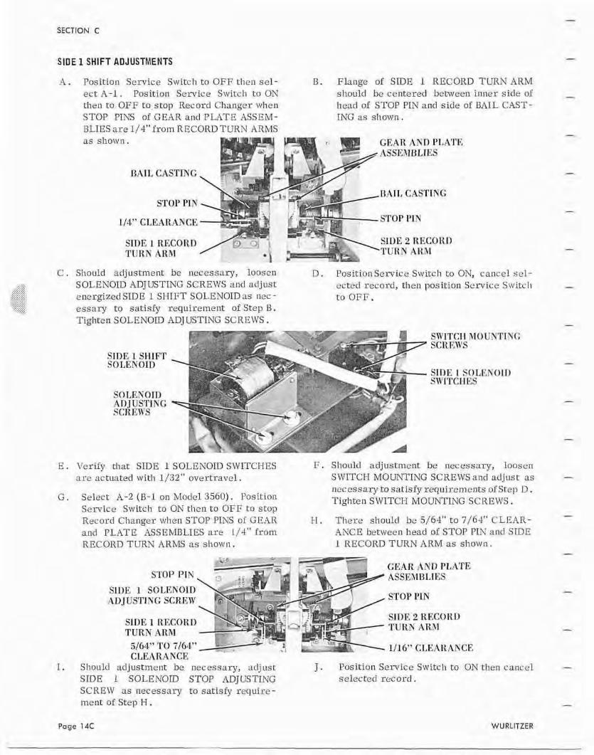
SlDE 1 SHIFT ADJUSTMENTS
-4. Position Service Sivitcb to OFF tlirn sel- B. Flange of STDE 1 RECORD T m N A R M ect A - l . Position Service Switch t o ON shoulcl bc centered between inner side o i t h e n to OEE to stop Record Cl~anger ~ v l ~ e n head of STOP PLN and side of BAIL CAST- STOP FINS of GEAR and PLATE ASSEM- ING as shown . BLIES are 1/4" Prom RECORD T U R N ARMS
I /4" CLFARANCE STOP PrPI
C . Sliould a d j u s f m e n t bc necessary, looscn D. Fosirion Service Swirch to ON, cancel scl- S OLENDTD ADJUSTING SCREWS and adjust ected record, then position Seivice SW i t c l~ energized SIDE 1 SHIFT SOLE NOID as nec - t o OFF. essary te satisfy requirement of Step B. Tighten SOLENOID ADJUSTING SCREWS.
SWTTCI-I 8IOUiVTTYT; SCRT;;VIS
SIDE Z SHIFT SOLENOIT)
STI3E I SOLENOIT) SlYl'rCHEs
S I)T,K K 07n AnJUSTlKG SCR mrs
E . Verify that SIDE 1 SOLENOID SlVITCHES F . Should arljustnicnt: be necessary, loosen a re actuated wit11 1/32" oaertravcl. SWITCH MOUNTING SCRELI1Sand a d j u s t as
necessary Lo satisfy requirements ~f Step D . G , Select A-2 ( B - l on Model 3560). Position Tighten S !ArITCR MOUNTING SCXE WS .
Service St~itc l i t o ON then ta OFF t o stop Record Clzangcr when STOP PIX5 a l GEAR 1-1. Therc s t ~ o u l d be 5/64" to 7/64" 'CLEAR- and PLATE ASSEMDLIES are I /4" horn ANCE between head of STOP PIN and SIDE RECORD Tm-5 AlZW as s h ~ w n . 1 RECORD TURN ARM as shown.
GEAR A N D PLATE STOP PIN ASSRXIBLmS
SlDE 1 SOLENOID ADJUSTING SCREW STOP P1.N
S113.E 1 RE'CC)R,U . SIDE 2 RECORD
TURN.4RM - TURN AR31
5JG4" T O 716.4" 111 6" CLElILAKCE CLLAR.A NCF,
I . Sl~ould adjustment be necessary, adjust J . Position Service Switch to ON then canccl SLDE 1 SOLENOID STOP ADJClSTINC selected record . SClZEW as necessary ta satisly 1-eqube- ment of Step H .
Page 14C WURtlTZER
SECTION C'
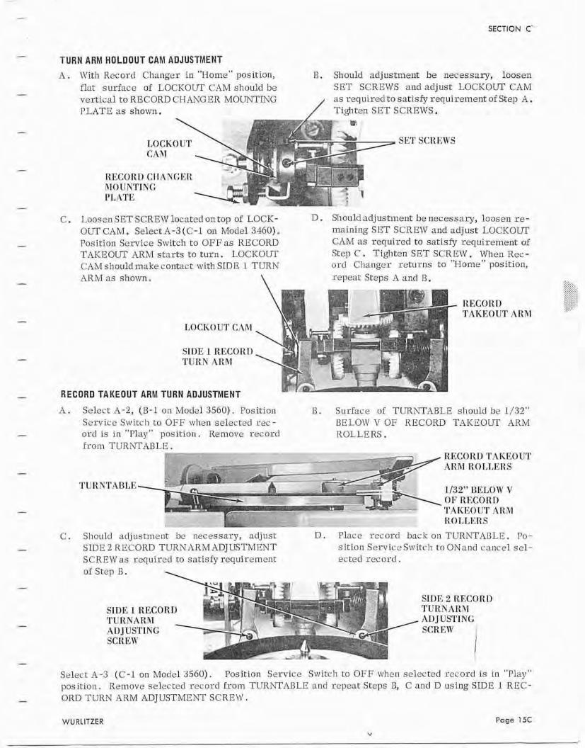
TURN ARM HOLPQUT CAM ADJUSTMENT A . \Ziit:tl Record Changer in "Home" position, T3. Should adjustment: be necessary, loosen
flar surface of LOCKOLT <:AM should be SET SCREWS and adjust LOCKOW CAM vcrt icd to RECORD CHANGER MOLlNTF4G as required to satisfy requirement of Step A. PLATE as sllown . / Tighten SET SCIIBWS.
SEE' SCREWS
RECORD CI1:INCER JIOITh'TINl: l":\?'E
C . Loosen SET SCREW located on top of LOCK- 13. Should adjustment be necessary, loosen re - OUT CAM. SelectA-3(C-1 on Model 3.160). maining SET SCREW and adjust LOCKOUT Posi~ion Service Switch to OFF as RECORD C.4M as required to satisfy requirmnent: of TrlKEOlTT ARM star ts t o turn. LOCKOUT Step C. Tigliten SET SCREW. When Rec- CAM shouldmake contact with SlDE 1 TURN arc1 Changcr retui:ns t o "I-Iome" position,
as shown.
RECORI) TATiI<OUT AR.R1
LOCTiOI!T CAR1
SIDE 1 Rl<CClIE13 TERK A R . M
RECORD TAKEOUT ARM TURN ADJUSTMENT
A . Select A-2, (B-4 on Model 35613) . Position B. Surhce of TURNTABLE should be 1/32" Scrvicc S\vItch t o OFF when selected rec- BELOW V OF RECORD TAKEOUT ARM ord is i n "Play" position. Remavc r eco rd ROLLERS . from TURNTAUPE.
-- - - - . 7-' - $*
- . RECORrJ TAKEOUT r;------- -
I - - - AIS.Rl R 01,1,@RS
. S&,.S 1/32" IJELOIV V OF Rl%COlIT) 'I'AICT<OliT A R 31
, ? < K O I,T,I<RS
C . Should adjustnlcnt be necessary, adjusl D. Place record barkonTURiWADLT:. Po- SIDE 2 RECORD TURKARMADJUSTMENT sirion Sez-viceS~viCcll t o ONa~irl cancel sel- SCREW as required to sat isfy sequiremcnt ected record. of Step B.
SIDE 2 RECORI) SIDE I REC0R.T) TUI.tYAKM T U IOY A RR.1 USTTN G An JUS'rl NG SCREW I
SCKE1V I Select -4-3 (C-1 on Model 3560). Position Servioc Switch to O F F whcn selected rccord is in "Play" position. Remove selected record from TURNTAl3LE and repeat Steps 0, C and D using S D E I REC- ORD TURN ARM ADJUSTMENT SCRElIr.
WURLITZER Page 15C
SECTION C
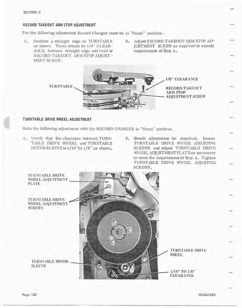
RECORD TAKEOUT ARMSTOP ADJUSTMENT
For the following adj ustrnent Record Changer must be in "I-Ioine" posit ion.
A . Position a straight edge on TURNTA13LE D . Adjust RECORD TAKEOUT ARM STOP AD- as shown. There should bc 1 / H W CLEAR- JUSTMENT SCREW as required to satisfy ANCE benrleen straight edge and Iwad of requbement of Step A. RECORn TAKEOUT i1RM STOP ADJUST - M E N T SCREW.
,c:<,'7 I!" +; . -$*-
I I &I
KECOR D TAKE0 lr'r AR,M STOP ALIJUSTRl iYNT SCR Ell'
..:.:,: ,-;..i:. ?,Y:;::: ...... ,,,,. :::. . . .
TURNTABLE DRIVE WHEEL AOJUSTMENT .. . .?..'. .,. ,...... '.',;.:: , ,' .,,.-. ._., ..:, . , . . . , , h t ~ k c the following adjusrment wi th the RECORD CHANGER in "Home" position.
A . Verify that the clearance between TURN- B. St~auld acljusfmcnt be required, loosen TABLE DRIVE WHEEL and TUItNTMLE TURNTABLE DMVE WI-IEE14 ADJUSTIKG MOTOR SLEESIE is 1/16"ro L/8" as shown. SCREWS and adjust TURhTABLE DRIVE
WI-IEELlDJUSTMEhTPLATEas necessary t o meet the requirement of Step A . Tighten TURNTPLBLE DRIVE WHEEL ADJUSTING SCREWS,
Page 1bC WURLITZER
SECTION C
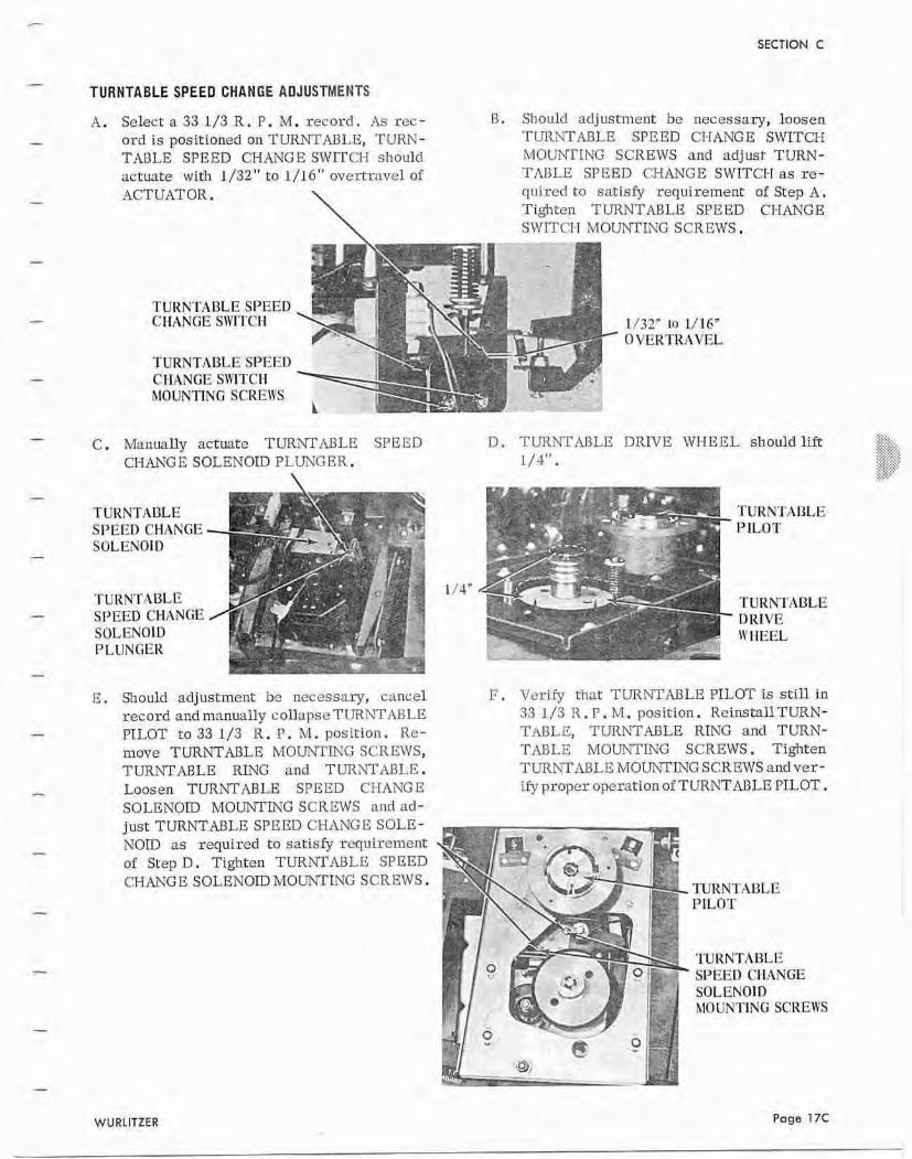
TURNTABLE SPEED CHANGE AOJUSTMENTS
A. Select a 33 1/3 R. P. M. record. r l s rcc- B. Should adjustment be necessary, loosen
ord is positioned on TURNTABLE, TURN- TURNTABLE SPEED CT-IANGB SWITCH TABLE SPEED CI-IAil'G E SWITCH should MOUNTING SCREWS and adjust TURN- actuate with 1/32" to 1 /16" overtravel 01 TABLE SPEED CHANGE SWITCH as rc- ACTUATOR.
\ quircd to satisfy requirement of Step A . Tighten TURNTABLE SPEED CI-IANGE SWITCIT MOUNTING SCREWS.
TURNTABLE SPEED CIiiZNGE SWITCl-I
TURNTABLE SPEED CHANGE SIIITCA hlOUNVNG SCREIYS
D . TUnNTMLG DRWE WHEEL should lift ..:,.,
C. Manually actuate TURNTABLE SPEED :*k::.: .:,.;;::. -.; >:.x<.,
CEIANG E SOLENOID PLUNGER. 1/4". ::,:..,..:.:.:. " ,...,_... ,. :?,;;?:< .,.,......
\ ;;:,?+ .,.,
TURNTABLE TURNTABLE SPEED CHlZNGE PILOT SOLENOID
TURNTABLE TURNTABLE SPEEII CHAYCiE DRIVE SOLENOLD I\' I-IEEL PLUNGER
E . Should adjustment bc necessary, cancel F. Verify that TURNTABLE PILOT is s t U in record and manually collapse TURNTIULE 33 1/3 R.P . hrI. position. ReinstaUTURN- PILOT ta 33 1 J3 R. P. M. position. Re- TABLE, TURNTABLE RING and TURN- move TURNTABLE MOUNTING SCREWS, TABLE M O n T I N G SCREWS S. Tighten TURhTABLE RING and TURhTABLE. TLJRhTRBLE MOUNTLUG SCREWS andver- Loosen TURhTABLE SPEED CHANGE @proper operation of TURNTMLE PILOT. SOLENOID MOUNl7ING SCREWS nnd ad- just TURNTABLE SPEED CHXYGE SOLE- NOTE as required to satisfy requirement of Step D . Tighten TURNTABLE SPEED CFIANGE SOLENOIIlMOUNTfNG SCREWS,
TURNTABLE SPEED CIlANGE
XIOUNTINF SCREWS
WURLITZER Page T7C
SECTION C
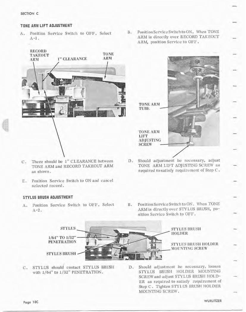
TONE ARM LIFT AOJUSTMENT
A . Fasition Service Switch to OFF. Select U, P o s i t i o ~ ~ Service Switch to OX, I\'Ilen TONE A-1 . ARM is direct ly over RECOIID T A I C E O m
ARM, lrrusitIvn SL'TVLCL' t o OFF.
R I<CORU 'T!~IIEO UT TONE .A]( I1 1" ClAEAI1ANCE ARM
TONE AK.IC1 TVBE /
D. Shaulrl adjustment be necessary, ad jus t TONE ARM LIFT ADJUSTING SCIIHZ1' ns requircd ta satisfy requil-cmei-rl: of Stcp C .
C . There should be 1" CLEAKINCH between TONE ARM and RECORD TAKEOUT ARM as shown.
E . Pasitioll Semicc Switch to ON and cancel selccred record.
STYLUS BRUSH ADJUSTMENT
B. Pos itioll Servioc S\vItch t o ON. W h c n TONE ARM is directly over Sn LUS BRUSH, po- sirion Service Switch to OFF.
?I. Position Senrice Switch te OFF, Select 9-2.
STYLUS STYLUS nRUSIl tl0 LTIEK
STYLUS BR USH
C. STYLUS should contact STYLUS I3RUSH D , Should a d j u s t m e n t bc necessary, loosen with 1/64'' to 1/32'' P E N E T M T I O N . STYLUS BRUST-I HOLDER ivTOCn\TTING
SCREWand urljust: STYLUS BRLElI ITOLD- E R as requiretl to satisfy requircmenr of Step C . Tighten STYLUS DRC7.SH I-IOLDHR MOUN'PTNG SCREW.
SECTION C
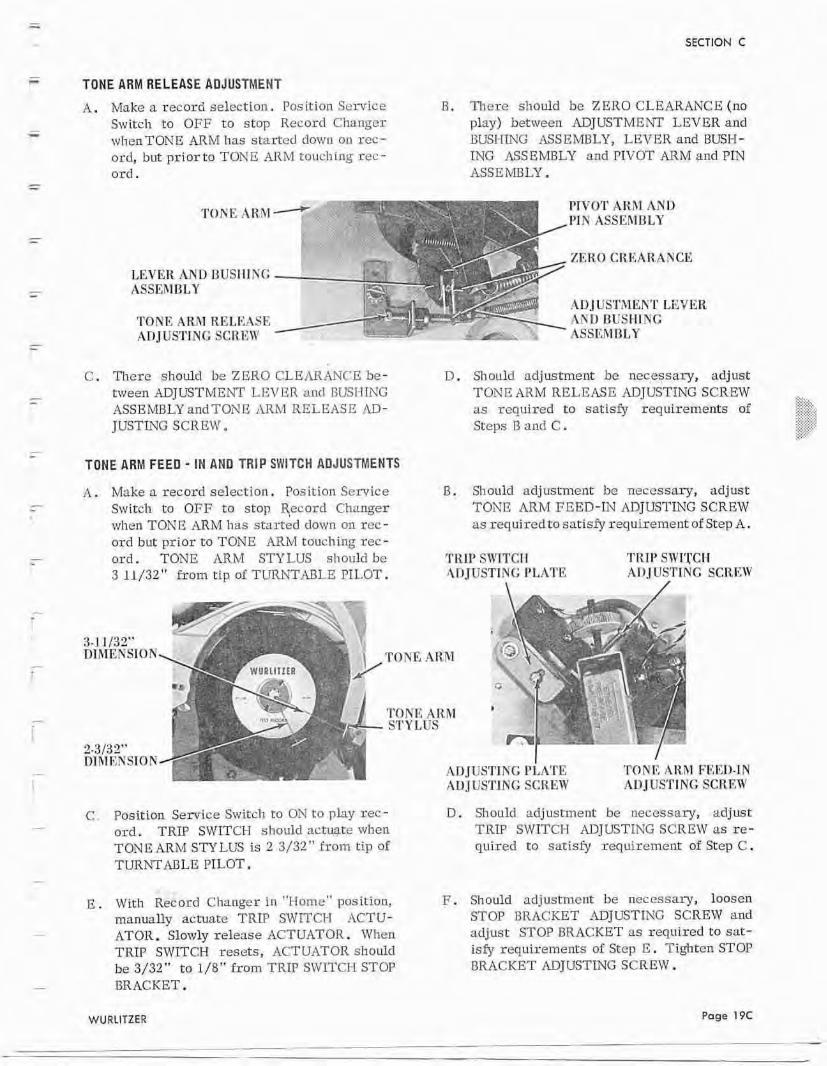
TONE ARM RELEASE ADJUSTMENT
A. Make n record selection. Position Scrvice B . Tlae~c sllould be ZERO CLEARANCE (nu Switch to OFF t o stop Record Cl~angcr plw) between ADJUSTMENT LEVER and wheaTONE ARM has started down on rec- EUSI-n7G ASSEMBLY, LEVER and BUSH- ord, but prior to TONE ARM touching rec - ING -ASSEMBLY and PIVOT ARM and PIN osd . ASSEhmLY.
TOKE ATEV- PWOT ARM AND I'IK ASSEMBLY
ZT;,RO CR.EAR,ANCE LEVER AND RlJSIIING - ASSLhIBLY
ADJUSTMENT LEXJER TONE ARhI RELEASE - h Y 1 J IJUSIIIYC AnJbSTING SCREW . .. . ASSKMDI,Y
C. There should be ZERO CLEARANrE be- ween ADJUSTMENT LEVER and GLEI-TING ASSEMELY andTONE ARM RELEASE AD- J USTZNG 5 C R EIV @
TONE ARM FEED - IN AND TRIP SWITCH ADJUSThlENTS
A . Make a record select ion. Posit ion Service Switch to OFF to stop qecard Changer when TONE ARh4 lias started d a m on rec- ord but pr ior to TONE ARM toucl~ ing rcc - ord. TONE ARM STYLUS should be 3 11/32'' from tip of TURNT.4nLE PLLOT.
D. Should adjustment be necessary, adjust TONE ARM RELEASE ADJUSTLNG SCREJV >%-:,. as requi.red t o satisfy requirements af :..<.7.>
.>'.:*:q:'. ,,:.,.:.,c,: :,:;.:.:.:.,. Seeps 13 and C . A:::9,?: .~.~,:.:,..- ..... ,:,: '.
B. Sl~ould adjustmefit he necessary, adjust TONE ARM FEED-LY ADJUSTING SCREW as requiredta tosatisfy requirement of Step A.
TH I!' SWTCH TRW SVITCIl Al)JlTSTJ!UG I'LATI': AIIIUSTlNG SCREIV
AT)JUSTlTVG PI,A'I'E TONIC AlthT FEED-IN AD J US'1'lNG SCREW AD JIISTI NC: SCR EW
C , Position Seriice Switch to ON to play rec- ord. TRLP S W I T W should actuate when TONE AnM STY Ltrs is 2 3/33" from tip of TUR?JTABLE PILOT.
e . With Record Changer i n "Home" position, manually actuate TRLP SWTTCT-I ACTU- ATOR. Slowly release ACTUATOR. When TRIP SWITCH resets, ACTUATOR should be 3/32" to l/8" £rom TRIP SWITCI-I STOP BRACKET.
D. Should ~d jus tment be necessary, adjust TRIP SWITCH ADJUSTING SCREW as re- quired to satisfy requirement: of Step C .
F. Shodd adjustment be necessary, 1oosea STOP BRACKET ~kDJUSTING SCREW and adjust STOP BRACKET as required to sat- isfy requirements of Step E . Tightcn STOP BRACKET ADJUSTING SCREW.
SECTION C
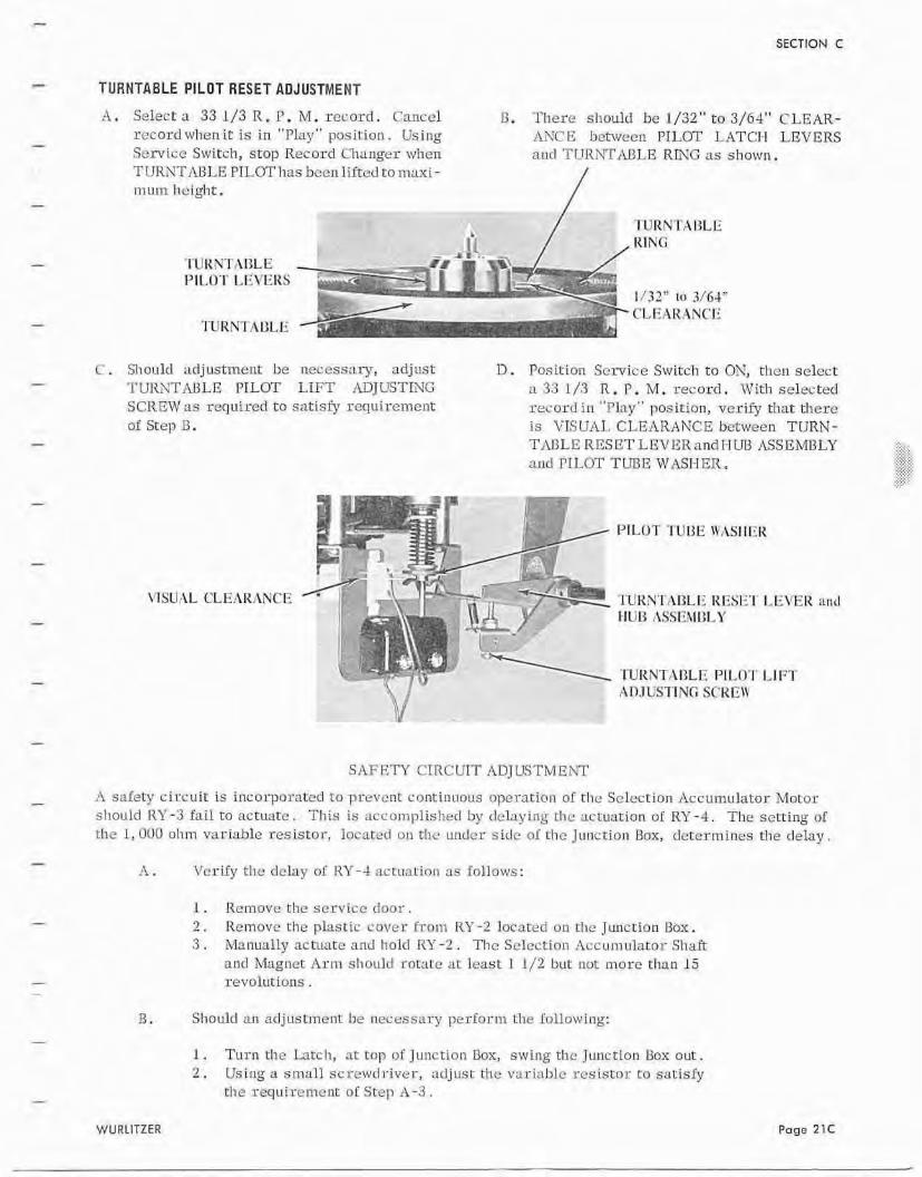
TURNTABLE PILOT RESET AQJUSTMENT
11. Select a 33 1/3 R . P . M. record. Cancel 13. There sIloulr1 be 1/32" t o 3/64" CLEAR- r e c o r d ~ v h c n i t is in "Play" position. Using kvC E between PILOT I+ATCI-I LEV ERS Scrvicc Switch, stop Record Changer wllerl and TURhTAnLE RING as shown. TIJRNTMLE PILOT has been liitccl to maxi - mum height.
- / 'I'URNTAl3t E , R I N G
C . Should adjustment: be nec.essnry, adjust D . Posit ion Scsvic e Switch to ON, then select T~J~EYTIWLE PILOT LIFT rlrDJLTSTING a 33 1 / 3 R, P. M, record . With selected SCREW as rccluired t o satisfy requ i ren~e i~ t record in "flay*' position, that there of Step B. is VISUAL CLEARANCE bemeell TURN-
TIULE RESET LEVER and HFJB MSEMBLY and TILOT TUI3E WASI-IER.
---- 'lTIHNTAI3LE RBSE'I' I-EVER and
'I'UIENTi\I3LE PILO'I' LIFT ADJUSTING SC'KI;,I\'
SAFETY CIRCUIT ADJUSTMENT
h safety circui t is incorpnrated t o ptevcnt continuous opernrion o i the Selection Accumulator Motor s l~ould R1'-3 fail t o actuatc. This i s accoimplished by clclaying t h c actuarion of RY-4. The setting sl t he 1, OOU ol11n variable resistor, locaret-1 on the unrlcr sicle of the Junctian Bmr , determines the clelay .
A . Verify t he delay 01 RY-4 actuation as Follows:
I . Remove the service d o o r . 2 . Removetheplast ic: rover f r o m RY-2 lucated untlic. Juncti~rrI3ox. 3 . Manually nchtate and llcld RZr-2 . Ttlc S e l e c t i o ~ ~ ~ ~ c c u m u l a r o r Shaft
and Magnet A T ~ sliould rornte ar least 1 1/2 but not more than 15 revolutions .
B. Should an adjustment be necessary perfortn the followlr~g:
1 . Turn tl-re Larch, at top uf J r ~ l ~ c t i v n Box, swing tile Junction Box out. 2. Using a smal l scretucl river, ad jus t the variable rcsistnr to satisfy
the requirc-mcnt of Step A-3.
WURLITZER Page 21C
SECTION C
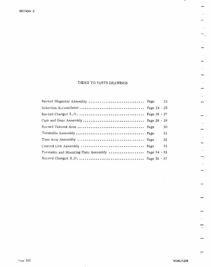
INDEX TO PARTS DRAWINGS
Record Magazine Assembly .............................. ................................... Selection Accumulator
................................... Record Changer L.H.
Cam and Gear Assembly ................................. Record Takeout A r m .................................... Turntable Assembly ..................................... Tone A r m Assembly .................................... Control Unit Assembly .................................. Turntable and Mounting Plate Assembly ................... Record Changer R.H. ...................................
Page 23
Page 24 . 25
Page 26 . 27
Page 28 . 29
Page 30
Page 3 1
Page 32
Page 33
Page 34 . 35
Page 36 . 37
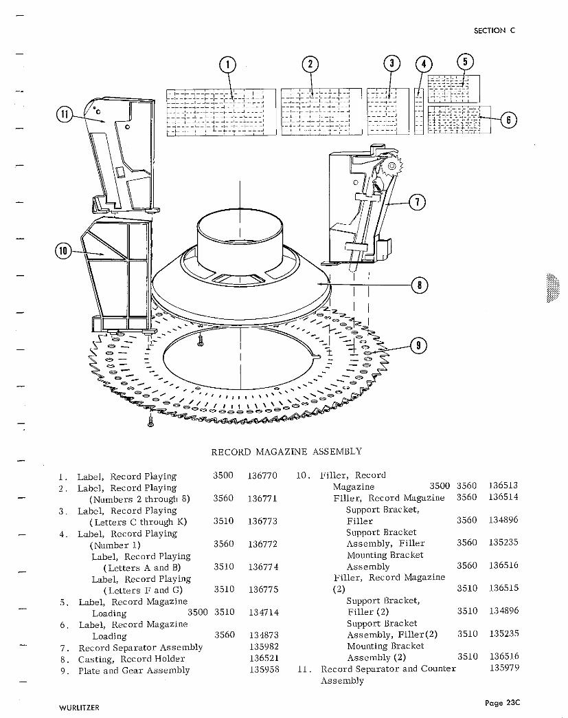
- SECTION C
RECORD MAGAZINE ASSEMBLY - 1. Label, Record Playing 3500 136770 10. Filler, Record 2 . Label, Record Playing Magazine 3500 3560 - (Numbers 2 through 8) 3560 136771 Filler, Record Magazine 3560
3 . Label, Record Playing Support Bracket, (Letters C through K) 3510 136773 Fil ler 3560
- 4 . Label, Record Playing Support Bracket (Number 1) 3560 136772 Assembly, Fil ler 3560 Label, Record Playing Mounting Bracket
- (Letters A and B) 3510 136774 Assembly 3560
Label, Record Playing Filler, Record Magazine
(Letters F and G) 3510 136775 (2) 3510 5 . Label, Record Magazine Support Bracket, -
Loading 3500 3510 134714 Fil ler (2) 3510 6 . Label, Record Magazine Support Bracket
Loading 3560 134873 Assembly, Fil ler(2) 3510 -. 7 . Record Separator Assembly 135982 Mounting Bracket
8 . Casting, Record Holder 136521 Assembly (2) 3510 9 . Plate and Gear Assembly 135958 11. Record Separator and Counter
- Assembly
Page 24C WURLITZER
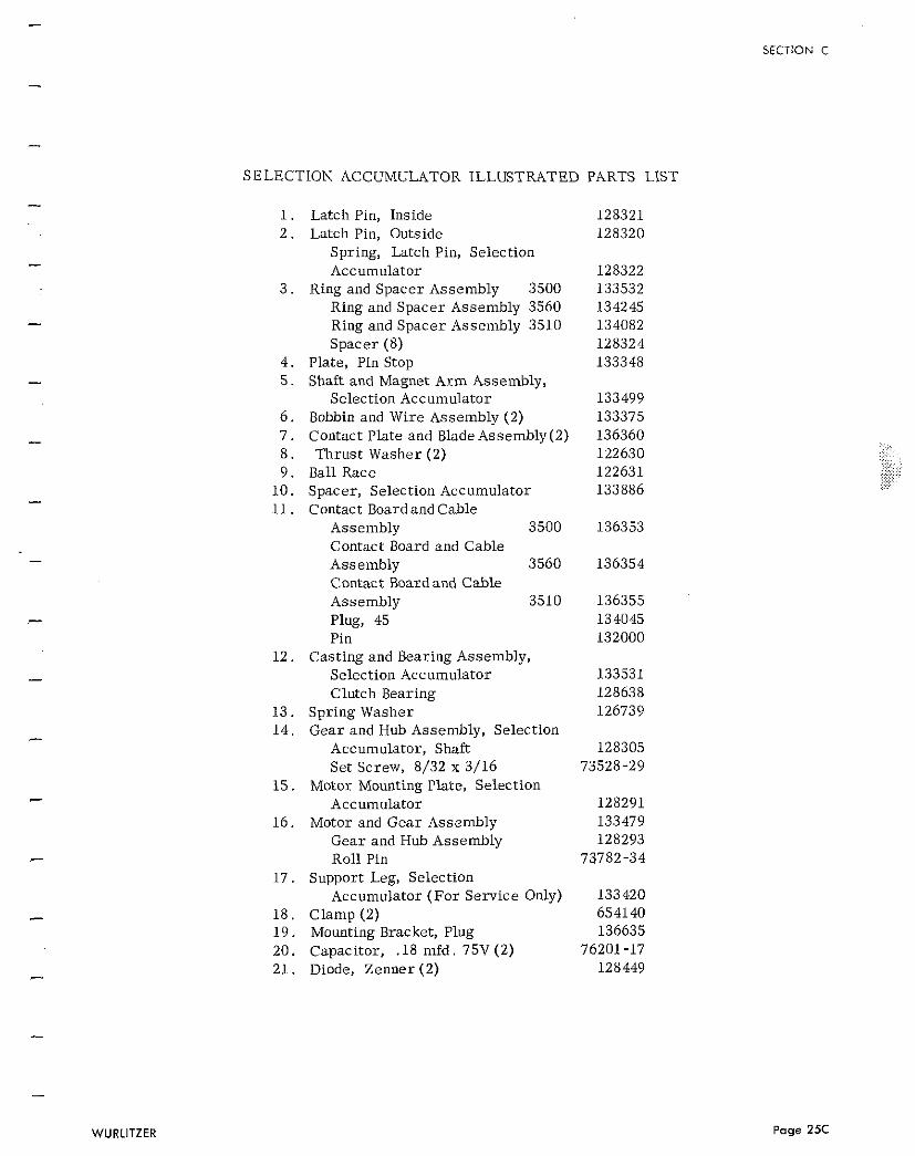
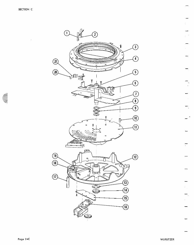
SECTION C
SELECTION ACCUMULATOR ILLUSTRATED PARTS LIST
1. Latch Pin, Inside 2 . Latch Pin, Outside
Spring, Latch Pin, Selection Accumulator
3 . Ring and Spacer Assembly 3500 Ring and Spacer Assembly 3560 Ring and Spacer Assembly 3510 Spacer (8)
4 . Plate, Pin Stop 5 . Shaft and Magnet Arm Assembly,
Selection Accumulator 6 . Bobbin and Wire Assembly (2) 7 . Contact Plate and BladeAssembly(2) 8 . Thrust Washer (2) 9 . Ball Race
10. Spacer, Selection Accumulator 11. Contact Boardand Cable
Assembly 3500 Contact Board and Cable Assembly 3560 Contact Board and Cable Assembly 3510 Plug, 45 Pin
12. Casting and Bearing Assembly, Selection Accumulator Clutch Bearing
13. Spring Washer 14 . Gear and Hub Assembly, Selection
Accumulator, Shaft Set Screw, 8/32 x 3/16
15. Motor Mounting Plate, Selection Accumulator
16. Motor and Gear Assembly Gear and Hub Assembly Roll Pin
17. Support Leg, Selection Accumulator (For Service Only)
18 . Clamp (2) 19 . Mounting Bracket, Plug 20. Capacitor, .18 mfd . 75V (2) 21. Diode, Zenner (2 )
SECTION C
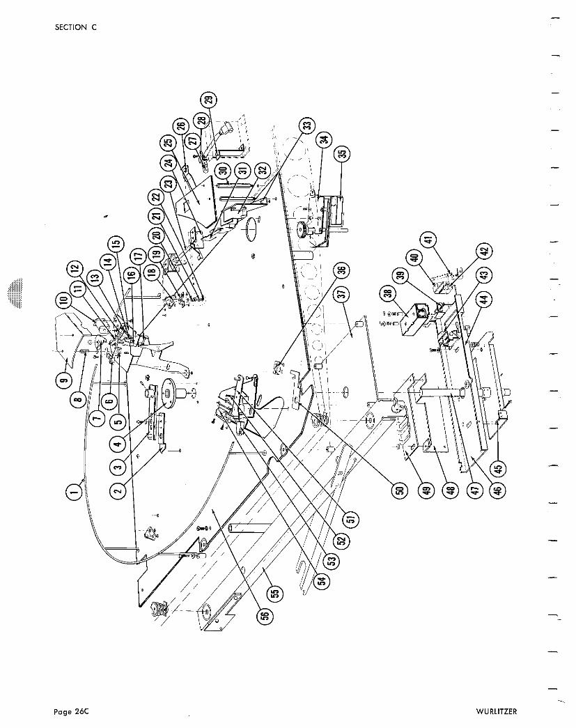
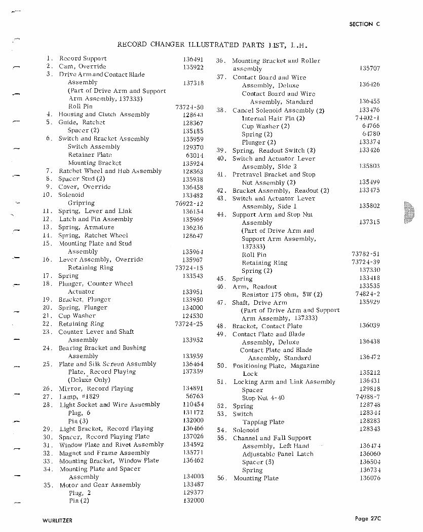
RECORD CHANGER ILLUSTRATED PARTS LIST, L.H.
1 . Record Support 2 . C a m , Overr ide 3 . Drive Armand Contact Blade
Asselnbly (Par t of Drive A r m and Support A r m Assembly, 137333) Roll Pin
4 Housing and Clutch Assembly 5 . Guide, Ratchet
Spacer (2) 6 . Switch and Bracket Asse~l lb ly
Switch Assembly Retainer Plate Mounting Bracket
7 . Ratchet Wheel and Hub Assembly 8 . Spacer Stud (2) 9 . Cover, Overr ide
10 . Solenoid Gripr ing
11. Spring, Lever and Link 1 2 . Latch and Pin Assellibly 1 3 . Spring, Armature 1 4 . Spring, Ratchet Wheel 1 5 . Mounting Plate and Stud
Assembly 1 6 . Lever Assembly, Overr ide
Retaining Ring 17 . Spring 1.8. Plunger, Counter Wheel
Actuator 1 9 . Bracket, Plunger 20. Spring, Plunger 21. Cup Washer 22 . Retaining Ring 23 . Counter Lever and Shaft
Assembly 24. Bearing Brac ket and Bushing
Assembly 25. Plate and Silk Screen Assembly
Plate, Record Playing elwe we Only)
26 . Mi r ro r , Record Playing 27 . Lamp, ;I829 28 . Light Socket and Wire Assembly
Plug, 6 Pin (3)
2 Liglit Bracket, Record Playing 30. Spacer , Record Playing Plate 3 1 . Window Plate and Rivet Assembly 3 2 . Magnet and F r a m e Assembly 3 3 . Mounting Bracket, Window Plate 3 4 . Mounting Plate and Spacer
Assembly 3 5 , Motor and Gear Assembly
Plug, 2 Pin (2)
Mounting Bracket and Roller assembly Contact Uoard and Wire
Assembly, Deluxe Contact Board and Wire
Assembly, Standard Cancel Solenoid Assembly (2)
I i l ter~ial Ha i r Pin (2) Cup Washer (2) Spring (2) Plunger (2)
Spring, Readout Switch (2) Switch and Actuator Lever
Assembly, Side 2 Pre t ravel Bracket and Stop
Nut Assembly (2) Bracket Assembly, Readout (2) Switch and Actuator Lever
Assembly, Side 1 Support A r m and Stop Nut
Assembly (Par t of Dr ive A r m and Support A r m Assembly, 137333) Roll Pin Retaining Ring Spring (2)
Spr ing A r m , Readout
Res i s to r 175 ohm, 5W (2) Shaft, Drive A r m
(Par t of Drive A r m and Support A r m Assembly, 137333)
Bracket, Contact Plate Contact Plate atid Blade
Assembly, Deluxe Contact Plate and Blade
Assembly, Standard Positioning Plate, Magazine
Lock Locking A r m and Link Assembly
Spacer Stop Nut 4-40
Spr ing Switch
Tapping Plate Solenoid Channel and Fal l Support
Assembly, Left Hand Adjustable Panel Latch Spacer (5) Spring
Mounting Plate
Page 27C
SECTION C
SECTION C
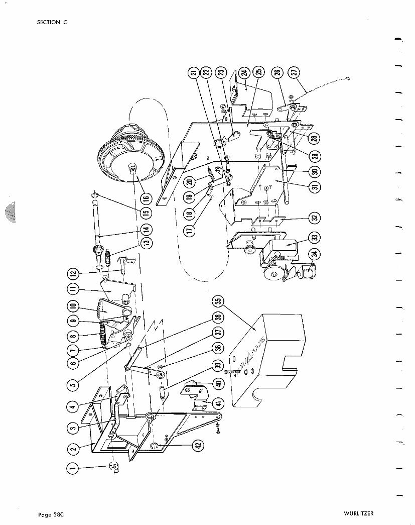
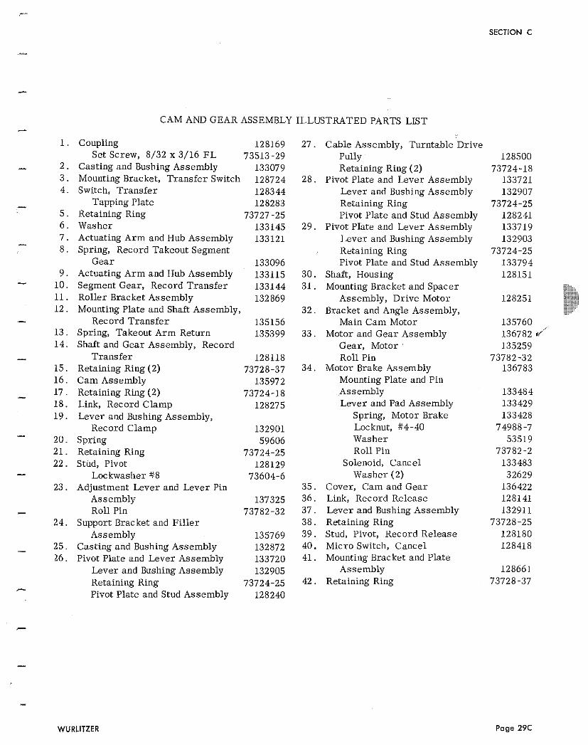
CAM AND GEAR ASSEMBLY ILLUSTRATED PARTS LIST - 1.
1. Coupling 128169 27. Cable Assembly, Turntable Drive Set Screw, 8/32 x 3/16 EL 73513-29 Pully - 2 . Casting and Bushing Assembly 133079 Retaining Ring (2)
3 . Mounting Bracket, Transfer Switch 128724 28. Pivot Plate and Lever Assembly 4 . Switch, Transfer 128344 Lever and Bushing Assembly
- Tapping Plate 128283 Retaining Ring 5 . Retaining Ring 73727-25 Pivot Plate and Stud Assembly 6 . Washer 133145 29. Pivot Plate and Lever Assembly
- 7 . Actuating Arm and Hub Assembly 133121 Lever and Bushing Assembly 8 . Spring, Record Takeout Segment Retaining Ring
Gear 133096 Pivot Plate and Stud Assembly 9 . Actuating Arm and Huh Assembly 133115 30. Shaft, Housing - 10 . Segment Gear, Record Transfer 133144 31. Mounting Bracket and Spacer
11. Roller Bracket Assembly 132869 Assembly, Drive Motor 12. Mounting Plate and Shaft Assembly, 32. Bracket and Angle Assembly, - Record Transfer 135156 Main Cam Motor 13 . Spring, Takeout Arm Return 135399 33. Motor and Gear Assembly 1 4 . Shaft and Gear Assembly, Record Gear, Motor :
- Transfer 128118 Roll Pin 15 . Retaining Ring (2) 73728-37 3 4 Motor Brake Assembly 16 . Cam Assembly 135972 Mounting Plate and Pin
- 17 . Retaining Ring (2) 73724-18 Assembly 18. Link, Record Clamp 128275 Lever and Pad Assembly 19. Lever and Bushing Assembly, Spring, Motor Brake
Record Clamp 132901 Locknut, #4-40 - 20. Spring 59606 Washer 21. Retaining Ring 73724-25 Roll Pin 22. Stud, Pivot 128129 Solenoid, Cancel - Lockwasher #8 73604-6 Washer (2) 23. Adjustment Lever and Lever Pin 35. Cover, Cam and Gear
Assembly 137325 36. Link, Record Release - Roll Pin 73782-32 37. Lever and Bushing Assembly 24. Support Bracket and Fi l le r 38. Retaining Ring
Assembly 135769 39. Stud, Pivot, Record Release
- 25. Casting and Bushing Assembly 132872 40. Micro Switch, Cancel 26. Pivot Plate and Lever Assembly 133720 41. Mounting Bracket and Plate
Lever and Bushing Assembly 132905 Assembly Retaining Ring 73724-25 42. Retaining Ring - Pivot Plate and Stud Assembly 128240
7
-
-
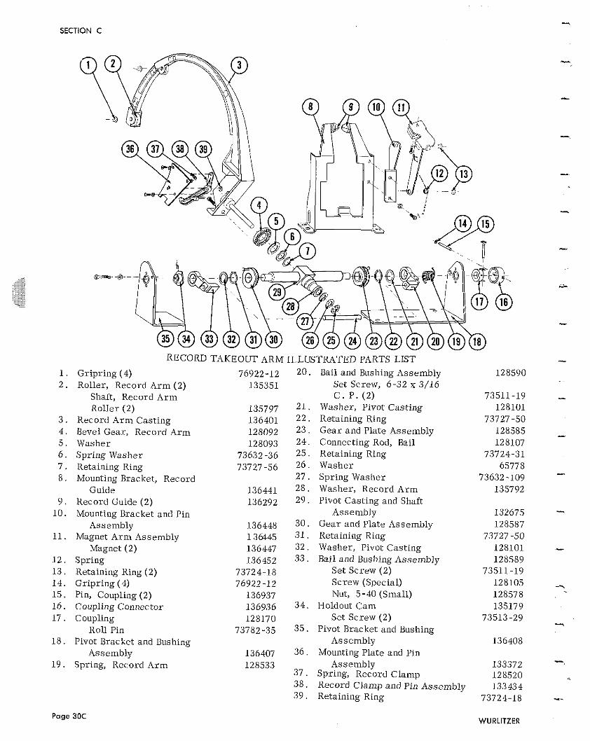
RECORD TAKEOUT ARM ILLUSTRATED PARTS LIST
Gr ipr ing (4) 76922-12 20 . Bail and Bushing Assembly Roller, Record A r m (2) 135351 Set Screw, 6-32 x 3/16
Shaft, Record A r m C . P . ( 2 ) Roller (2) 135797 2 1 . Washer , Pivot Cast ing
Record A r m Cast ing 136401 22 . Retaining Ring Bevel Gear , Record A r m 128092 23 . Gea r and Plate Assembly Washer 128093 24. Connecting Rod, Bail Spr ing Washer 73632 -36 25 . Retaining Ring Retaining Ring 73727.56 26 . Washer Mounting Bracket, Record 2 7 . Spring Washer
Guide 136441 2 8 . Washer , Record A r m Record Guide (2) 136292 29 . Pivot Cast ing and Shaft Mounting Bracket and Pin Assembly
Assembly 136448 30 . Gea r and Plate Assembly Magnet A r m Assembly 136445 31 . Retaining Ring
Magnet (2) 136447 32. Washer, Pivot Cast ing Spring 136452 33. Bail and Bushing Assembly Retaining Ring (2) 73724.18 Se t Screw (2) Gr ipr ing (4) 76922-12 Screw (Special) Pin, Coupling (2) 136937 Nut, 5-40 (Small) Coupling Connector 136936 34 . Holdout C a m Coupling 128170 Set Screw (2)
Roll Pin 73782-35 35 . Pivot Bracket and Bushing Pivot Bracket and Bushing Assembly
Assemblv 136407 36 . Mounting Plate and Pin Spring, Record A r m
Page 30C
128533 Assembly 3 7 . Spring, Record Clamp 38 . Record Clamp and Pin Assembly 3 9 . Retaining Ring
SECTION C
2-
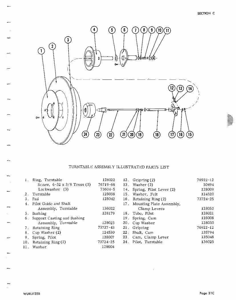
TURNTABLE ASSEMBLY ILLUSTRATED PARTS LIST
Ring, Turntable Screw, 6-32 x 3/8 T rus s (3) Loc kwasher (3)
Turntable Pad Pilot Guide and Shaft
Assembly, Turntable Bushing Support Casting and Bushing
Assembly, Turntable Retaining Ring Cup Washer (2) Spring, Pilot Retaining Ring (2) Washer
Gripring (2) Washer (2) Spring, Pilot Lever (2) Washer, Fe l t Retaining Ring (2) Mounting Plate Assembly,
Clamp Levers Tube, Pilot Spring, Cam Cup Washer Gripring Shaft, Cam Cam, Clamp Lever Pilot, Turntable
WURLITZER Page 31C
SECTION C
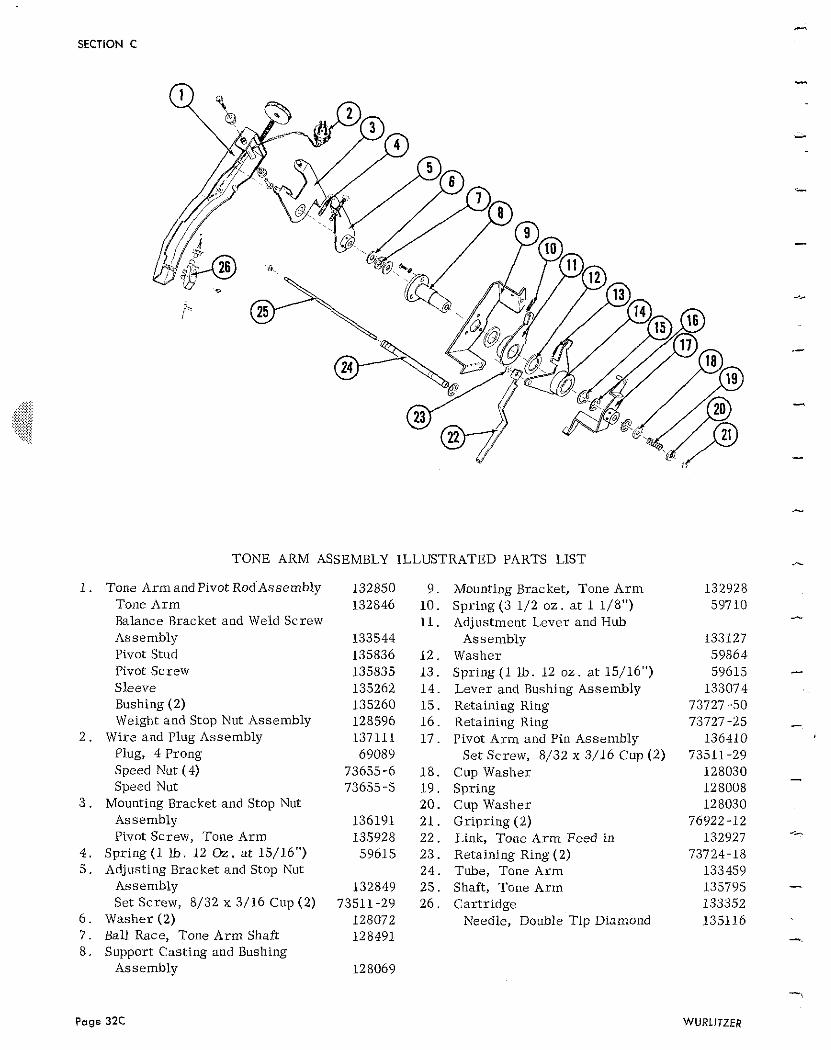
TONE ARM ASSEMBLY ILLUSTRATED PARTS LIST
I . Tone Arm and Pivot RodAssembly 132850 9 . Mounting Bracket, Tone Arm Tone Arm 132846 10. Spring (3 1/2 oz . a t 1 1/8") Balance Bracket and Weld Screw 11. Adjustment Lever and Hub Assembly 133544 Assembly Pivot Stud 135836 12 . Washer Pivot Screw 135835 13. Spring (1 Lb. 12 oz. a t 15/16") Sleeve 135262 14. Lever and Bushing Assembly Bushing (2) 135260 15. Retaining Ring Weight and Stop Nut Assembly 128596 16. Retaining Ring
2 . Wire and Plug Assembly 137111 17. Pivot Arm and Pin Assembly Plug, 4 Prong 69089 Set Screw, 8/32 x 3/16 Cup (2) Speed Nut (4) 73655-6 18. Cup Washer Speed Nut 73655-5 19 . Spring
3 . Mounting Bracket and Stop Nut 20. Cup Washer Assembly 136191 21. Gripring (2) Pivot Screw, Tone Arm 135928 22. Link, Tone Arm Feed in
4 . Spring ( I Ib. 12 Oz. a t 15/16") 59615 23. Retaining Ring (2) 5 . Adjusting Bracket and Stop Nut 24. Tube, Tone Arm
Assembly 132849 25. Shaft, Tone Arm Set Screw, 8/32 x 3/16 Cup (2) 73511-29 26. Cartridge
6 . Washer (2) 128072 Needle, Double Tip Diamond 7 . Ball Race, Tone Arm Shaft 128491 8 . Support Casting and Bushing
Assembly 128069
SECTION C
&
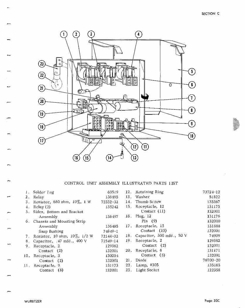
CONTROL UNIT ASSEMBLY ILLUSTRATED PARTS LIST
Solder Lug Relay Resistor, 680 ohm, 10%, 1 W Relay (2) Sides, Bottom and Bracket
Assembly Chassis and Mounting Str ip
Assembly Snap Bushing
Resistor, 10 ohm, 1070, 1/2 W Capacitor, .47 mfd ., 400 V Receptacle, 2
Contact (2) Receptacle, 3
Contact (2) Receptacle, 9
Contact (8)
Retaining Ring Washer T h u d Screw Receptacle, 12
Contact (11) Plug, 12
Pin (9) Receptacle, 15
Contact (13) Capacitor, 500 mfd ., 50 V Receptacle, 2
Contact (2) Receptacle, 6
Contact ( 5 ) Diode Lamp, #305 Light Socket
WURLITZER Page 33C
SECTION C
SECTION C
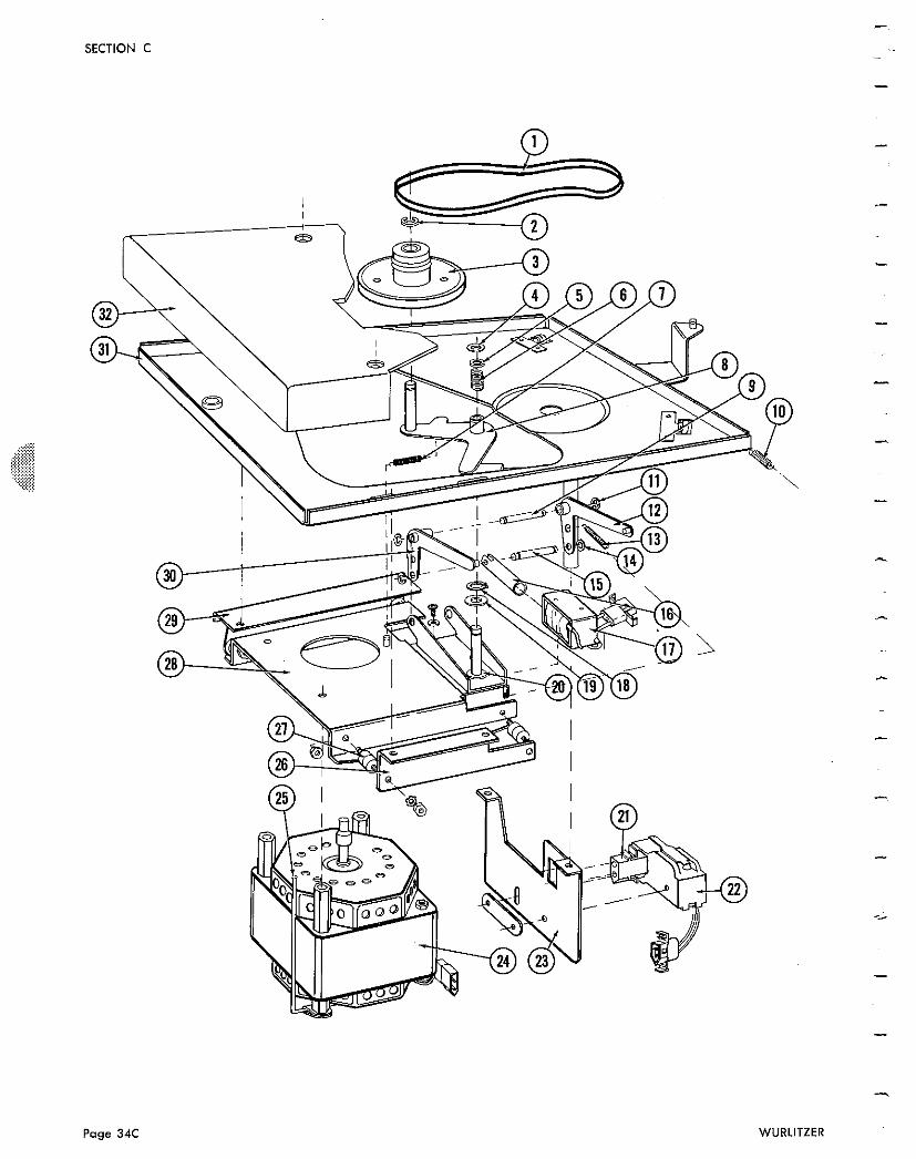
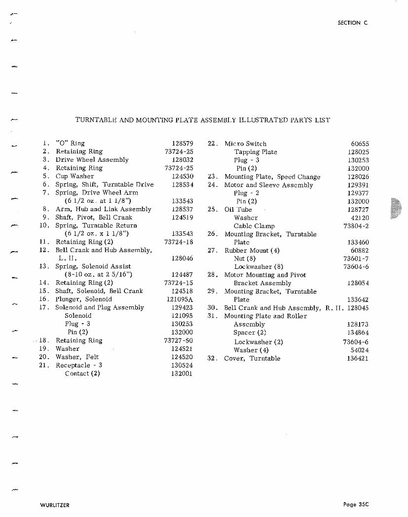
- TURNTABLE AND MOUNTING PLATE ASSEMBLY ILLUSTRATED PARTS LIST
"0" Ring Retaining Ring Drive Wheel Assembly Retaining Ring Cup Washer Spring, Shift, Turntable Drive Spring, Drive Wheel A r m
(6 1/2 o z . a t 1 1/8") Arm, Hub and Link Assembly Shaft, Pivot, Bell Crank Spring, Turntable Return
(6 1/2 o z . x 1 1/8") Retaining Ring (2) Bell Crank and Hub Assembly, L. H .
Spring, Solenoid Ass is t (8-10 oz . a t 2 5/16")
Retaining Ring (2) Shaft, Solenoid, Bell Crank Plunger, Solenoid Solenoid and Plug Assembly
Solenoid Plug - 3 Pin (2)
Retaining Ring Washer Washer, Fel t Receptacle - 3
Contact (2)
22. Micro Switch 60655 Tapping Plate 128025 Plug - 3 130253 Pin (2) 132000
23. Mounting Plate, Speed Change 128026 24. Motor and Sleeve Assembly 129391
Plug - 2 129377 .~.. Pin (2) 132000 W?., ....... . . . . . . :::. :::::. .,. . . . . . . , ,
25. Oil Tube 128727 *$$: =<:::: . . . . . . . ....., .....,
Washer 42120 :..,.. .,. .:......
Cable Clamp 73804-2 26. Mounting Bracket, Turntable
Plate 133460 27. Rubber Mount (4) 60882
Nut (8) 73601 -7 Loc kwasher (8) 73604-6
28. Motor Mounting and Pivot Bracket Assembly 128054
29 . Mounting Bracket, Turntable Plate 133642
30. Bell Crank and Hub Assembly, R. H . 128045 31. Mounting Plate and Roller
Assembly 128173 Spacer (2) 134864 Lockwasher (2) 73604-6 Washer (4) 54024
32. Cover, Turntable 136421
SECTION C
63
WURLITZER
SECTION C
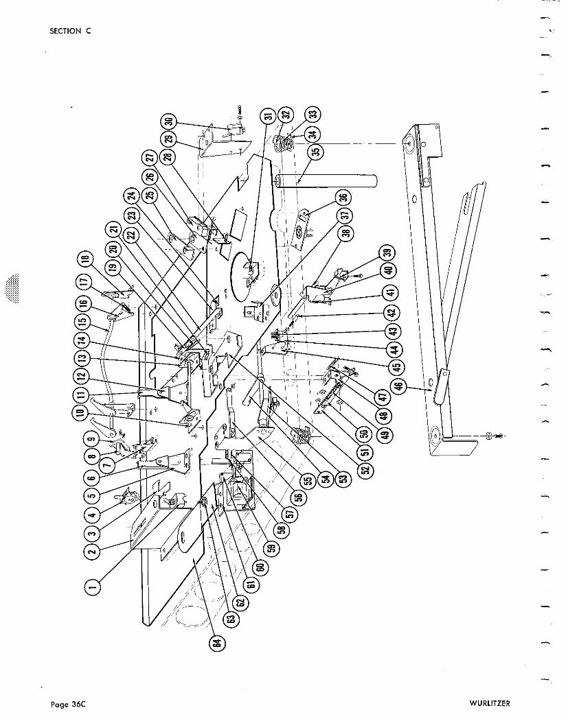
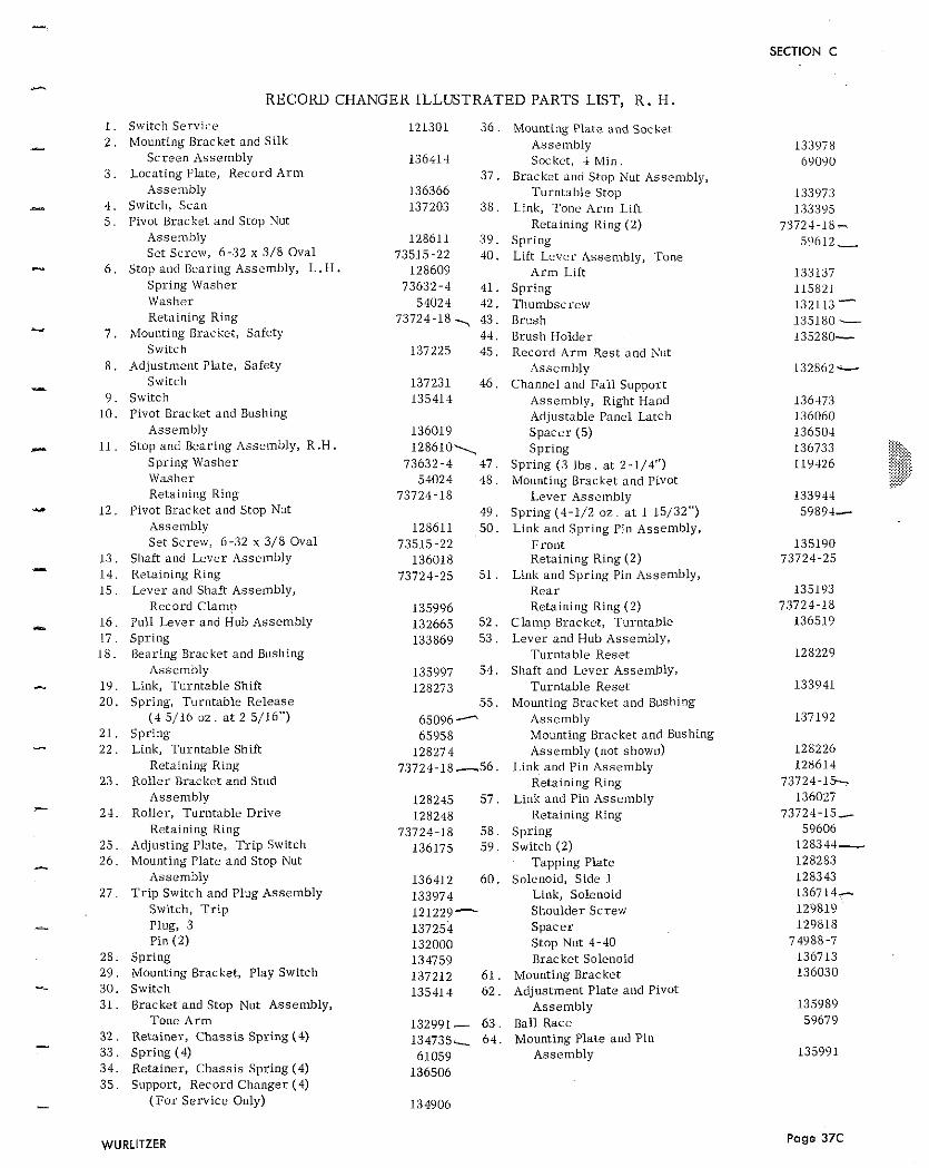
RECORD CHANl
1. S\vitcli Service 2 . Mounting Bracket and Silk
Screen Assembly 3 . Locating Plate, Record A r m
Assenibly 4 . Switch, Scan 5 pivot Bracket and Stop Nut
i issembly Set Screw, 6-32 x 3/8 Oval
6 . Stop and Bearing Assembly, L . H . Spring Washer \Vastier Retaining Ring
7 . Mounting Bracket, Safety Switch
8 . Adjustment Plate, Safety Switch
9 . Switch 10 . Pivot Bracket and Bushing
Assembly 11. Stop and Bearing i lssembly, R.H.
Spring Washer \Vaslier Retaining Ring
12 . Pivot Bracket and Stop Nut Asse~i ibly Set Screw, 6-32 x 3/8 Oval
13 . Shaft and Lever Assembly 14 . Retaining Ring 1 5 . Lever and Shaft Assembly,
Record Clamp 16 . Pull Lever and Hub Assembly ! 7 Spring
18 . Bearing Brac kct and Bushing Assembly
19. Link. Turntable Shift 20. Spring, Turntable Release
( 4 5/16 oz. a t 2 5/16") 21. Spring 22. Link, Turntable Shift
Retaining Ring 23. Roller Brackct and Stud
Assembly 2-1. Roller, Turntable Drive
Retaining Ring 25. Adjusting Plate, T r i p Switch 26 . Mounting Plate and Stop Nut
Assembly 2 7 . T r i p Switch and Plug Assembly
Switch, T r i p Plug, 3 Pin (2)
28. Spring 2 9 . Mounting Bracket, Play Switch 30. Switch 31. Bracket and Stop Nut Assembly,
Tone A r m 32. Retainer, Chass i s Spring (4) 3 3 . Spring (4) 34. Retainer, Chassis Spring (4) 3 5 . Support, Record Changer (4)
( F o r Service Only)
SER ILLUSTRATED PARTS LIST, R . H . 121301 3 6 . Mounting Plate and Socket
Assembly 136414 Socket, 4 Mi11 .
37. Bracket and Stop Xut Assembly, 136366 Turntable Stop 137203 3 8 . Link, Tone A r m Lift
Retaining Ring (2) 128611 3 9 . Spring
73515-22 40. Lift Lever Assembly, Tone 128609 A r m Lift
73632-4 41. Spring 54024 42. l l iumbscrew
73724-18 7 43. Brush 44. Brush Holder
137225 45. Record A r m Rest and Nut Assembly
137231 46. Channel and F a l l Support 135414 Assembly, Right Hand
Adjustable Panel Latch 136019 Spacer (5) 128610\ Spring
73632-4 47. Spring (3 l b s . a t 2-1/4") 54024 48. Mounting Bracket and Pivot
73724-18 Lever Assembly 49. Spring (4-1/2 o z . a t 1 15/32")
128611 5 0 . Link and Spring Pin Assembly, 73515-22 Fron t
136018 Retaining Ring (2) 73724-25 5 1 . Link and Spring Pin Assembly,
R e a r 135996 Retaining Ring (2) 132665 52 . C lamp Bracket, Turntable 133869 5 3 . Lever and Hub Assembly,
Turntable Reset 135997 54 . Shaft and Lever Assembly, 128273 Turntable Reset
5 5 . Mounting Bracket and Bushing 65096- Assembly 65958 Mounting Bracket ant1 Bushing
128274 Assembly (not shown) 73724-18 -56. Link and Pin Assembly
Retaining Ring 128245 5 7 . Link and Pin Assembly 128248 Retaining Ring
73724-18 58 . Spring 136175 5 9 . Switch (2)
Tapping Plate 136412 60 . Solenoid, Side 1
133974 Link, Solenoid 121229- Shoulder Screw 137254 Spacer 132000 Stop Nut 4-40
134759 Bracket Solenoid 137212 6 1 . Mounting Bracket 135414 6 2 . Adjustment Plate a~nd Pivot
Assembly 132991 - 6 3 . Ball Race 1 3 4 7 3 5 ~ 6 4 . Mounting Plate and Pin
61059 Assembly 136506
Page 37C
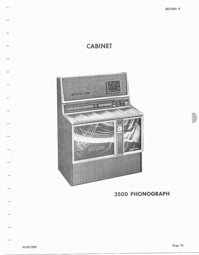
- SECTION D
A
WURLITZER
3500 PHONOGRAPH
Page 10
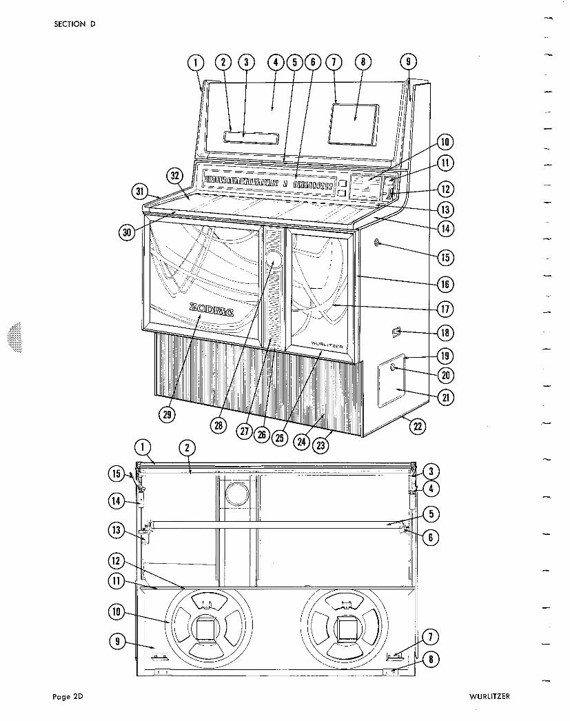
Page 2D WURLITZER
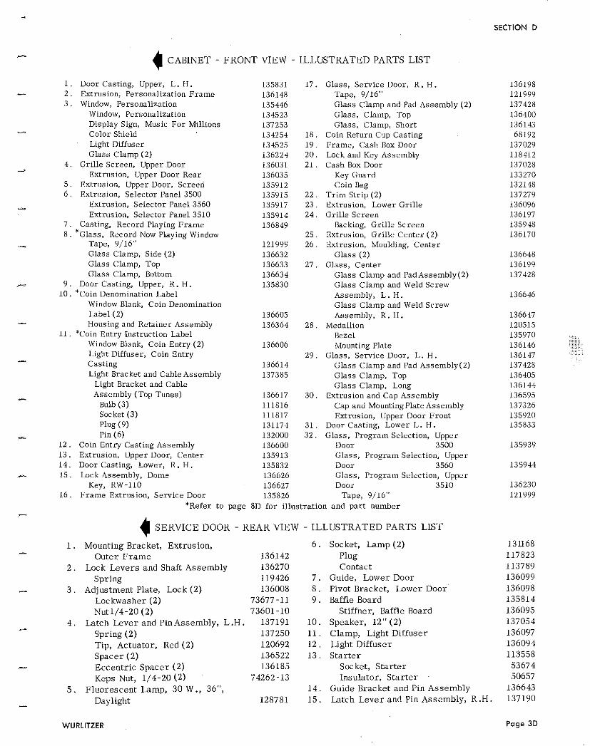
SECTION D * C A B I N E T - FRONT V I E W - ILLLETMTED PARTS LIST
1. Door Casting, Upper, L. H . 2 . Extrusion, Personalization F r a m e 3 . Window, Personalization
Window, Personalization Display Sign, Music F o r Millions Color Shield Light Diffuser Glass C lamp (2)
4 . Gri l le Screen, Upper Door Extrusion, Upper Door Rear
5 . Extrusion, Upper Door, Screed 6 . Extrusion, Selector Panel 3500
Extrusion, Selector Panel 3560 Extrusion, Selector Panel 3510
7 . Casting, Record Playing F r a m e 8 . lass, Record Now Playing Window
Tape, 9/16" Glass Clamp, Side (2) Glass Clamp, Top Glass Clamp, Bottom
9 . Door Casting, Upper, R. H . 1 0 . *Coin Denomination Label
Window Blank, Coin Denomination Label (2) Housing and Retainer Assembly
11. *Coin Entry Instruction Label Window Blank, Coin Entry (2) Light Diffuser, Coin Entry Cast ing Light Bracket and CabieAssembly
Light Bracket and Cable Assembly (Top Tunes)
Bulb (3) Socket (3) Plug (9) Pin (6)
1 2 . Coin Entry Cast ing Assembly 13. Extrusion, Upper Door, Cen te r 1 4 . Door Casting, Lower, R . H . 5 Lock Assembly, Dome
Key, RW-110 1 6 . F r a m e Extrusion, Se rv ice Door
*Refer t o
136617 111816 111817 131174 132000 136600 135913 135832 136626 136627 135826
page 8D f o r illusl
4 SERVICE DOOR - REAR V I E W
1. M o u n t i n g B r a c k e t , E x t r u s i o n , O u t e r F r a m e
2 . Lock Levers a n d Shaf t A s s e m b l y S p r i n g
3 . A d j u s t m e n t P la t e , L o c k (2) L o c k w a s h e r (2) Nut1 /4 -20 (2 )
4 . L a t c h Lever a n d Pin A s s e m b l y , L . H
S p r i n g (2) T i p , A c t u a t o r , Red (2 ) S p a c e r (2 ) E c c e n t r i c S p a c e r (2 ) K e p s Nut, 1 / 4 - 2 0 (2)
5 . F l u o r e s c e n t L a m p , 30 W ., 36",
Day l igh t
t r a t io
Glass , Se rv ice Door, R. H . Tape, 9/16" Glass Clamp and Pad Assembly (2) Glass, Clamp, Top Glass , Clamp, Short
Coil] Return Cup Cast ing F r a m e , Cash Box Door Lock and Key Assembly Cash Box Door
Key Guard Coin Bag
T r i m Str ip (2) Extrusion, Lower Gr i l l e Gri l le Sc reen
Backing, Gr i l l e Sc reen Extrusion, Gri l le Cen te r (2) Extrusion, Moulding, Cen te r
Glass (2) Glass , Cen te r
Glass C lamp and PadAssembly(2) Glass C lamp and Weld Screw Assembly, L . H . Glass Clamp and Weld Screw Assembly, R . H.
Medallion Bezel Mounting Plate
Glass , Service Door, L. H . Glass C lamp and Pad Assembly(2) Glass Clamp, Top Glass Clamp, Long
Extrusion and Cap Assembly Cap and Mountingplate Assembly Extrusion, Upper Door F ron t
Door Casting, Lower L . H . Glass , P rogram Selection, Upper
Door 3500 Glass , P rogram Selection, Upper Door 3560 Glass , Program Selection, Upper Door 3510
Tape, 9/16" n and p a r t number
- I L L U S T R A T E D P A R T S LIST
6 . Socke t , L a m p (2) P lug C o n t a c t
7 . Guide , L o w e r D o o r 8 . Pivot B r a c k e t , L o w e r Door 9 . Baffle Board
S t i f f n e r , Baffle Board 1 0 . S p e a k e r , 12" (2 ) 11. C l a m p , L igh t D i f f u s e r 1 2 . L i g h t D i f f u s e r 13. Starter
S o c k e t , S t a r t e r I n s u l a t o r , S t a r t e r
1 4 . G u i d e B r a c k e t a n d P i n A s s e m b l y
15. L a t c h L e v e r a n d Pin A s s e m b l y , R .H.
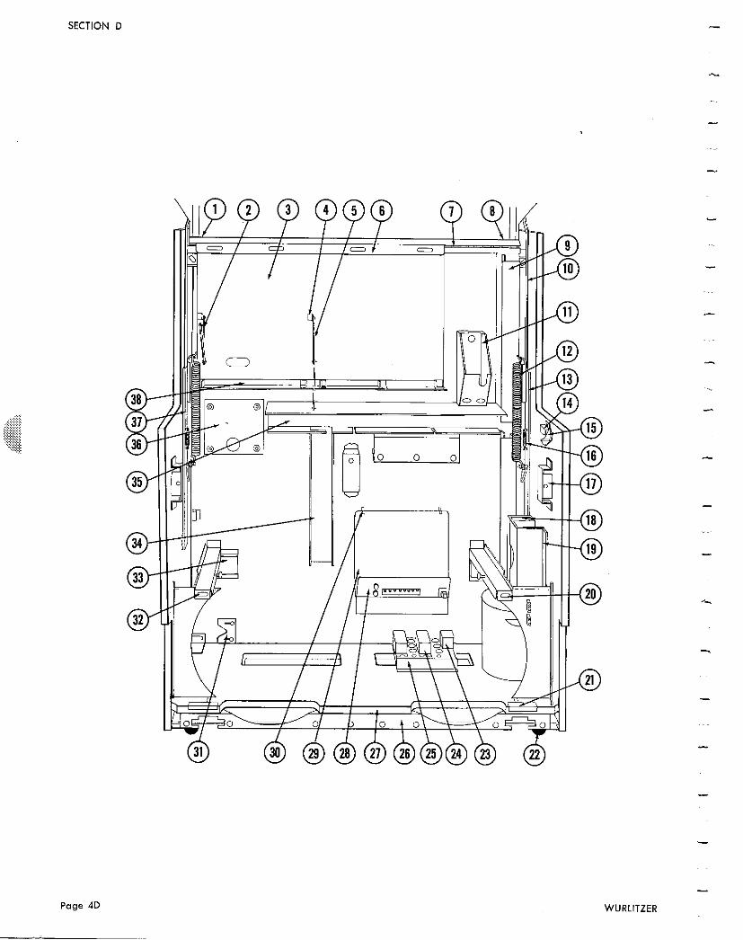
SECTION D
Page 4D
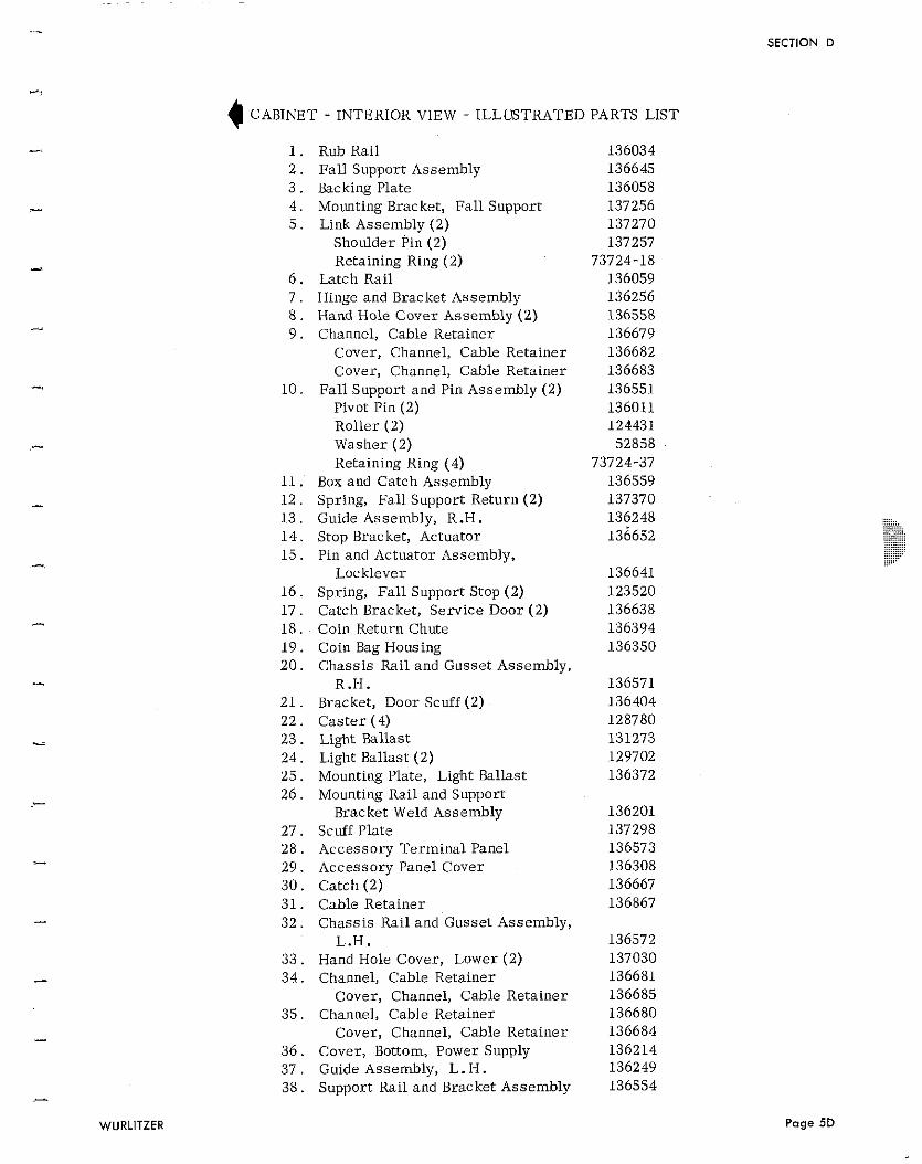
4 CABINET - INTERIOR VIEW - ILLUSTRATED PARTS LIST
Rub Rail Fa l l Support Assembly Backing Plate Mounting Bracket, Fa l l Support Link Assembly (2)
Shoulder Pin (2 ) Retaining Ring (2)
Latch Rail Hinge and Bracket Assembly Hand Hole Cover Assembly (2) Channel, Cable Retainer
Cover , Channel, Cable Retainer Cover , Channel, Cable Retainer
Fall Support and Pin Assembly (2) Pivot Pin (2) Rol ler (2) Washer (2) Retaining Ring (4)
Box and Catch Assembly Spring, Fa l l Support Return (2) Guide Assembly, R.H. Stop Bracket, Actuator Pin and Actuator Assembly,
Locklever Spring, Fall Support Stop (2) Catch Bracket, Serv ice Door (2) Coin Return Chute Coin Bag Housing Chass i s Rail and Gusset Assembly,
R.H. Bracket, Door Scuff (2 ) C a s t e r (4) Light Ballast Light Ballast (2) Mounting Plate, Light Ballast Mounting Rail and Support
Bracket Weld Assembly Scuff Plate Accessory Te rmina l Panel Accessory Panel Cover Catch (2) Cable Retainer Chass i s Rai l and Gusset Assembly,
L.H. Hand Hole Cover , Lower (2) Channel, Cable Retainer
Cover, Channel, Cable Retainer Channel, Cable Retainer
Cover, Channel, Cable Retainer Cover , Bottom, Power Supply Guide Assembly, L. H. Support Rail and Bracket Assembly
SECTION D
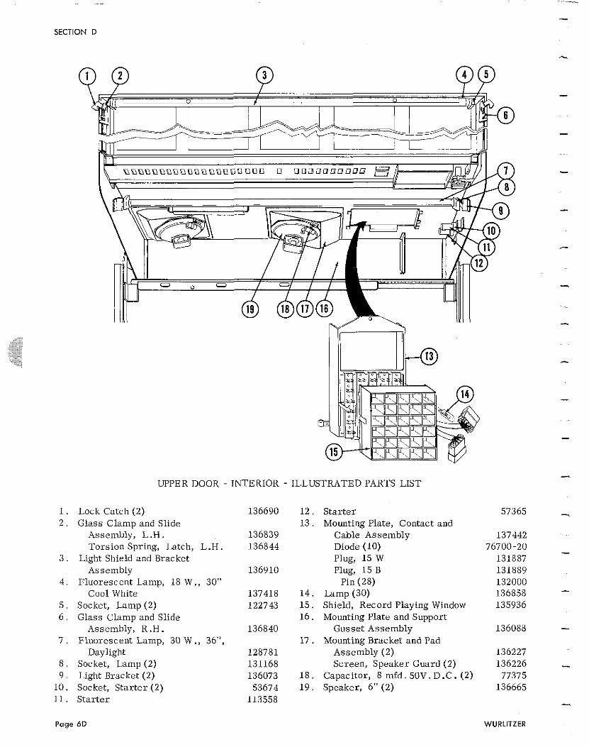
SECTION D
UPPER DOOR - INTERIOR - ILLUSTRATED PARTS LIST
1. Lock Catch (2) 2 . Glass Clamp and Slide
Assembly, L .H. Torsion Spring, Latch, L.H .
3 . Light Shield and Bracket Assembly
4 . Fluorescent Lamp, 18 W., 30" Cool White
5 . Socket, Lamp (2) 6 . Glass Clamp and Slide
Assembly, R . H . 7 . Fluorescent Lamp, 30 W ., 36",
Daylight 8 . Socket, Lamp (2) 9 . Light Bracket (2)
10 . Socket, S t a r t e r (2) 11. S ta r t e r
S t a r t e r Mounting Plate, Contact and
Cable Assembly Diode (10) Plug, 15 W Plug, 1 5 B
Pin (28) Lamp (30) Shield, Record Playing Window Mounting Plate and Support
Gusset Assembly Mounting Bracket and Pad
Assembly (2) Screen, Speaker Guard (2)
Capacitor, 8 mfd. 50V. D.C. (2) Speaker, 6" (2)
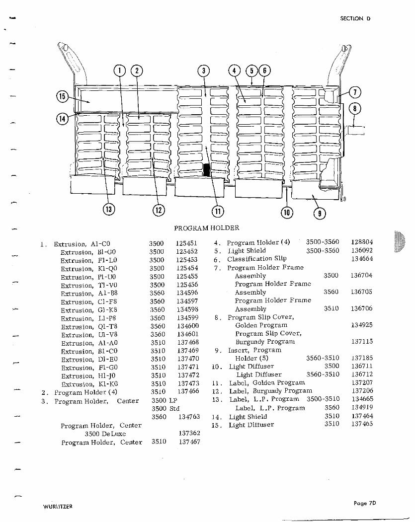
Extrusion, A1-CO Extrusion, B1-GO Extrusion, El-LO Extrusion, K1-QO Extrusion, PI-UO Extrusion, TI-VO Extrusion, A1-B8 Extrusion, Cl-F8 Extrusion, G1-K8 Extrusion, Ll-P8 Extrusion, Q1-T8 Extrusion, LJ-V8 Extrusion, A1-A0 Extrusion, B1 -CO Extrusion, Dl-EO Extrusion, EL-GO Extrusion, H1-JO Extrusion, K1-KO
Program Holder (4) Program Holder, Center
Program Holder, Center 3500 De Luxe - Program Holder, Center
PROGRAM HOLDER
3500 125451 4 . Program Holder ! 4) 3500-3560 3500 125452 5 . Light Shield 3500-3560 3500 125453 6 . Classification Slip 3500 125454 7 . Program Holder F rame 3500 125455 Assembly 3500 3500 125456 Program Holder Erame 3560 134596 Assembly 3560 3560 134597 Program Holder Frame 3560 134598 Assembly 3510 3560 134599 8 . Program Slip Cover, 3560 134600 Golden Program 3560 134601 Program Slip Cover, 3510 137468 Burgundy Program 3510 137469 9 . Insert, Program 3510 137470 Holder (5) 3560-3510 3510 137471 10. Light Diffuser 3500 3510 137472 Light Diffuser 3560-3510 3510 137473 11. Label, Golden Program 3510 137466 12 . Label, Burgundy Program 3500 LP 13 . Label, L.P. Program 3500-3510 3500 Std Label, L.P. Program 3560 3560 134763 14 . Light Shield 3510
15 . Light Diituser 3510 137362
3510 137467
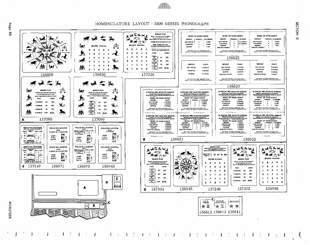
71 NOMENCLATURE LAYOUT - 3500 SERIES PHONOGRAPH V) 0 m
. . .
SECTION E
SEQUENCE OF OPERATIONS
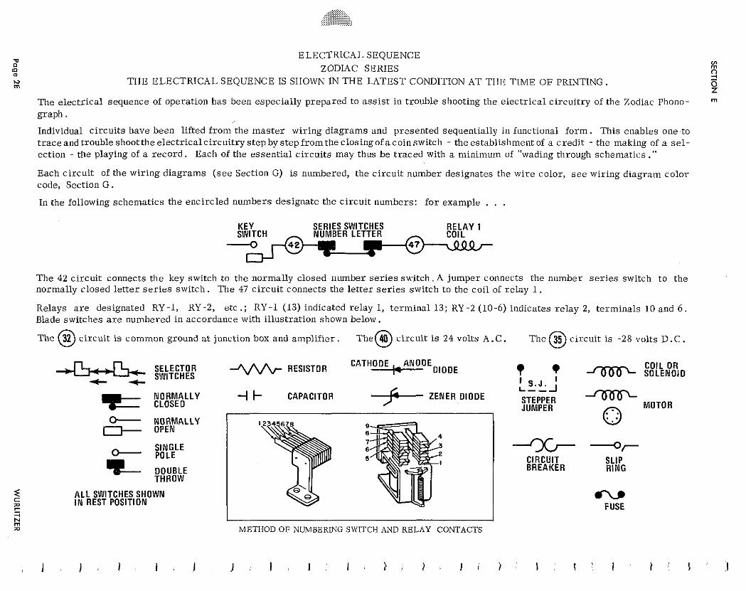
ELECTRICAL SEQUENCE ZODIAC SERIES z
THE ELECTRICAL SEQUENCE IS SHOWN IN THE LATEST CONDITION AT THE TIME OF PRINTING. 2 0 z
The electrical sequence of operation has been especially prepared to ass is t in trouble shooting the electr ical circuitry of the Zodiac Phono- graph.
Individual circuits have been lifted from the master wiring diagrams and presented sequentially in functional f o r m . This enables one to t race and trouble shoot the electr icalcircuitry step by step f rom the closing of a coin switch - the establishment of a credit - the making of a se l - ection - the playing of a record . Each of the essential circuits may thus be traced with a minimum of "wading through schematics ." Each circuit of the wiring diagrams ( see Section G) is numbered, the circuit number designates the wire color, s e e wiring diagram color code, Section G . In the following schematics the encircled numbers designate the circuit numbers: f o r example . . .
KEY SERIES SWITCHES R E L A Y 1
The 42 circuit connects the key switch to the normally closed number se r i e s switch. A jumper connects the number se r i e s switch to the normally closed let ter se r i e s switch. The 47 circuit connects the let ter se r i e s switch to the coil of relay 1.
Relays a r e designated RY-1, RY-2, etc .; RY-1 (13) indicated relay 1, terminal 13; RY-2 (10-6) indicates relay 2, terminals 10 and 6 . Blade switches a r e numbered in accordance with illustration shown below.
common ground a t junction box and amplif ier . The 24 volts A.C. The 35 clrcult 1s 28 volts D.C. 0. SELECTOR RESISTOR I- DIODE CATHODE ,ANODE COIL OR
C 4 SWITCHES ? ' SOLENOIO
I S .J . I
ZENER OlODE L--_l
N O R M A L L Y CLOSE0
4 k CAPACITOR STEPPER JUMPER -
MOTOR
b NORMALLY OPEN
SINGLE POLE
DOUBLE THROW
A L L SWITCHES SHOWN I N REST POSITION
,- m n METHOD O F NUMBERING SWITCH AND RELAY CONTACTS
-x- -r CIRCUIT SLIP BREAKER R ING
CV FUSE
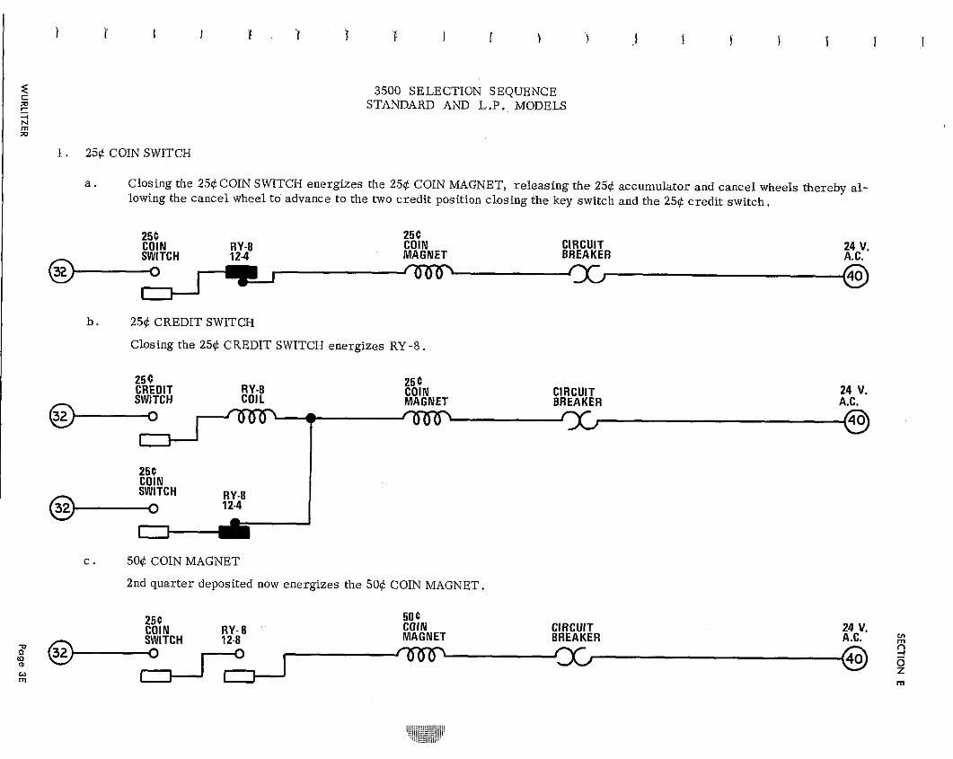
3500 SELECTION SEQUENCE STANDARD AND L.P. MODELS
1. 259 COIN SWITCH
a . Closing the 256 COIN SWITCH energizes the 25$ COIN MAGNET, releasing the 256 accumulator and cancel wheels thereby a l - lowing the cancel wheel to advance to the two credit position closing the key switch and the 256 credit switch.
25C 25C COIN RY-8 COIN CIRCUIT
BREAKER 24 V.
12-4 MAGNET A.C.
b . 25d CREDIT SWITCH
Closing the 25d CREDIT SWITCH energizes RY -8.
25 C CREDIT RY-8 COIN CIRCUIT 24 V.
25 C COIL MAGNET BREAKER A.C.
T -
c . 506 COIN MAGNET
2nd quar ter deposited now energizes the 50$ COIN MAGNET.
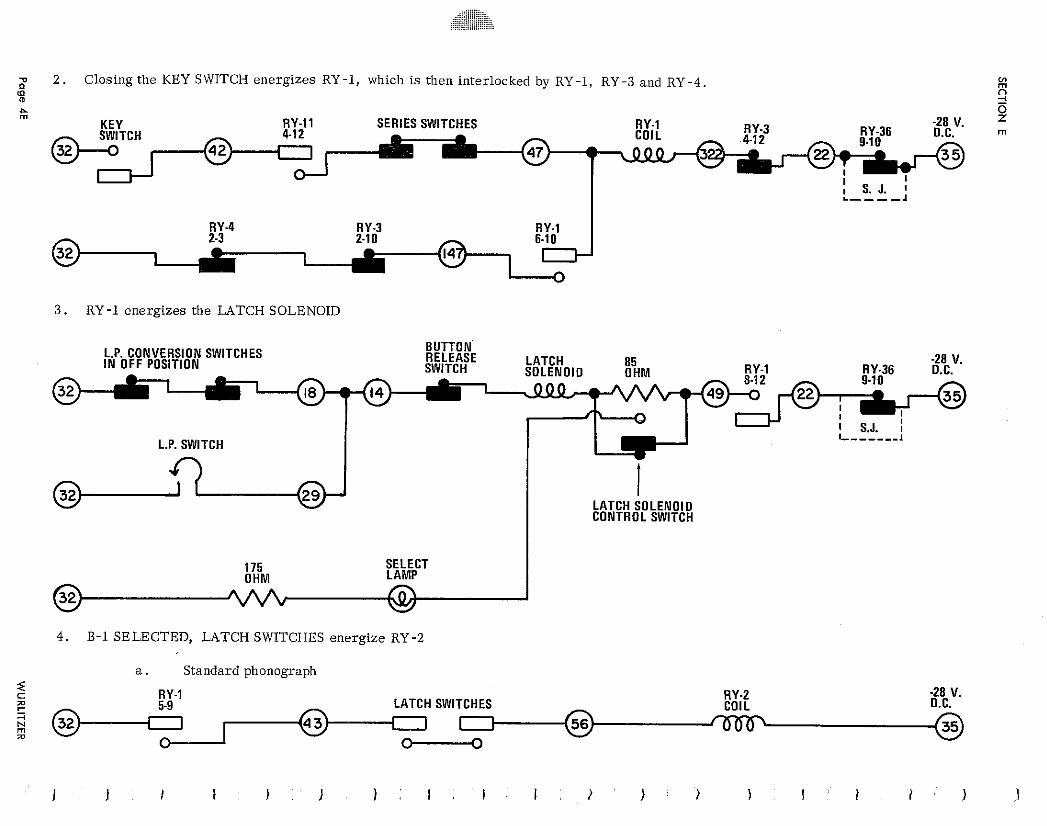
;p 2 . Closing the KEY SWITCH energ izes RY -1, which is then interlocked by RY -1, RY -3 and RY -4. V) rn
(II a 7 - %
K E Y SERIES SWITCHES S rn
3 . RY -1 energ izes the LATCH SOLENOID
L.P. CONVERSION SWITCHES BUTTON I N OFF POSITION
L.P. SWITCH
LATCH SOLENOID CONTROL SWITCH
175 SELECT O H M LAMP
4. B - l SELECTED, LATCH SWITCHES energ ize RY-2
a . Standard phonograph =z c RY-1 RY-2 -28 V. z LATCH SWITCHES COIL D.C. " & rn I z 0 -
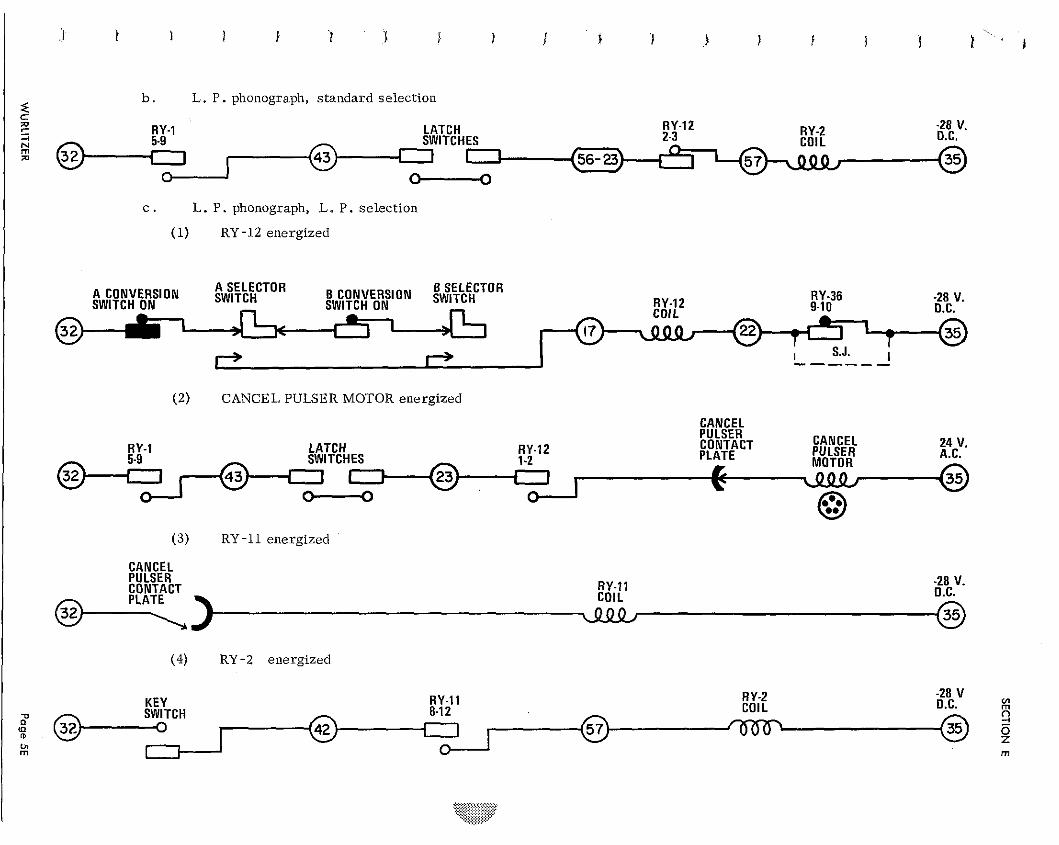
b. L. P. phonograph, standard selection
RY-1 LATCH RY-12 RY-2 2 8 V. SWITCHES O.C. a I 0
c. L. P. phonograph, L. P. selection
(1) RY-12 energized
A CONVERSION SWITCH A B CONVERSION SWITCH B SELECTOR RY-36 -28 V. RY-12 9-10 O.C.
- T
I S.J. 1 ------ (2) CANCEL PULSER MOTOR energized
CANCEL PULSER
RY-1 LATCH RY-12 CONTACT CANCEL PULSER
24 V. e&Tc 43 PLATE E MOTOR A.C. -
(3) RY-11 energized
CANCEL PULSER CONTACT RY-11
.28 V. COl L O.C.
(4) RY-2 energized
RY-11 RY-2 -28 V KEY
8-12 COIL D.C. m
WCH I m 2 2
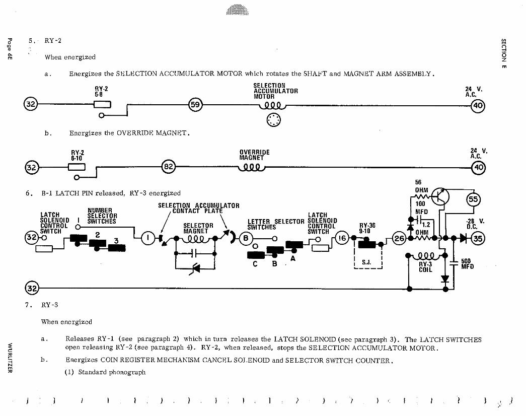
5 . RY-2 (D
h rn When energized
a . Energizes the SELECTION ACCUMULATOR MOTOR which ro ta tes the SHAFT and MAGNET ARM ASSEMBLY.
RY-2 SELECTION ACCUMULATOR 24 V. 5-9 MOTOR A.C.
b . Energizes the OVERRIDE MAGNET.
RY-2 OVERRIDE 24 V. MAGNET A.C.
56
6. B-1 LATCH PIN released, RY -3 energized
SELECTION ACCUMULATOR CONTACT PLATE
When energized
a . Releases RY-1 ( s e e paragraph 2) which in t u rn r e l e a se s the LATCH SOLENOID ( s e e paragraph 3) . The LATCH SWITCHES < C
open re leas ing RY -2 ( s e e paragraph 4). RY -2, when re leased , s tops the SELECTION ACCUMULATOR MOTOR. m r + b . Energizes COIN REGISTER MECHANISM CANCEL SOLENOID and SELECTOR SWITCH COUNTER. k io (1) Standard phonograph
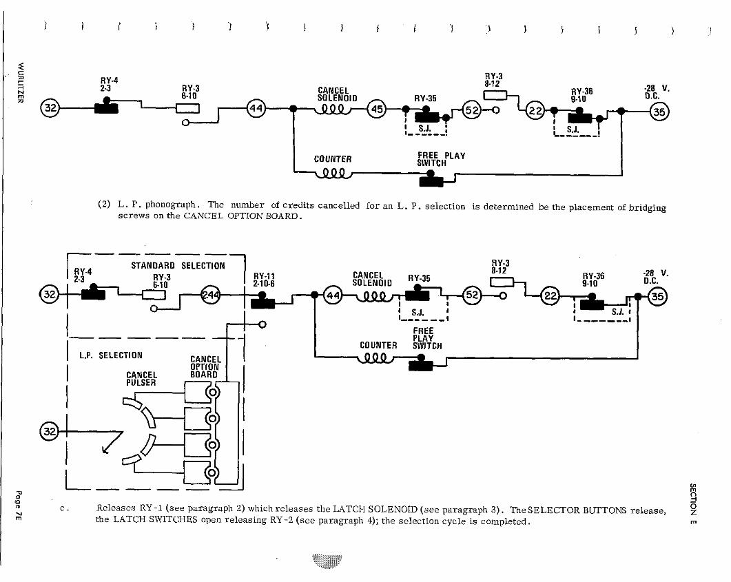
RY-4 RY-3 2-3 RY.3 CANCEL RY-36 -28 V.
RY-35
7 T I
S.J. I - - - - - - . L- - - -, - .
FREE PLAY SWITCH
(2) L. P. phonograph. The number of credits cancelled for an L. P. selection is determined be the placement of bridging screws on the CANCEL OPTION BOARD.
c . Releases RY -1 (see paragraph 2) which releases the LATCH SOLENOID (see paragraph 3) . TheSELECTOR BUTTONS release, the LATCH SWITCHES open releasing RY-2 (see paragraph 4); the selection cycle is completed.
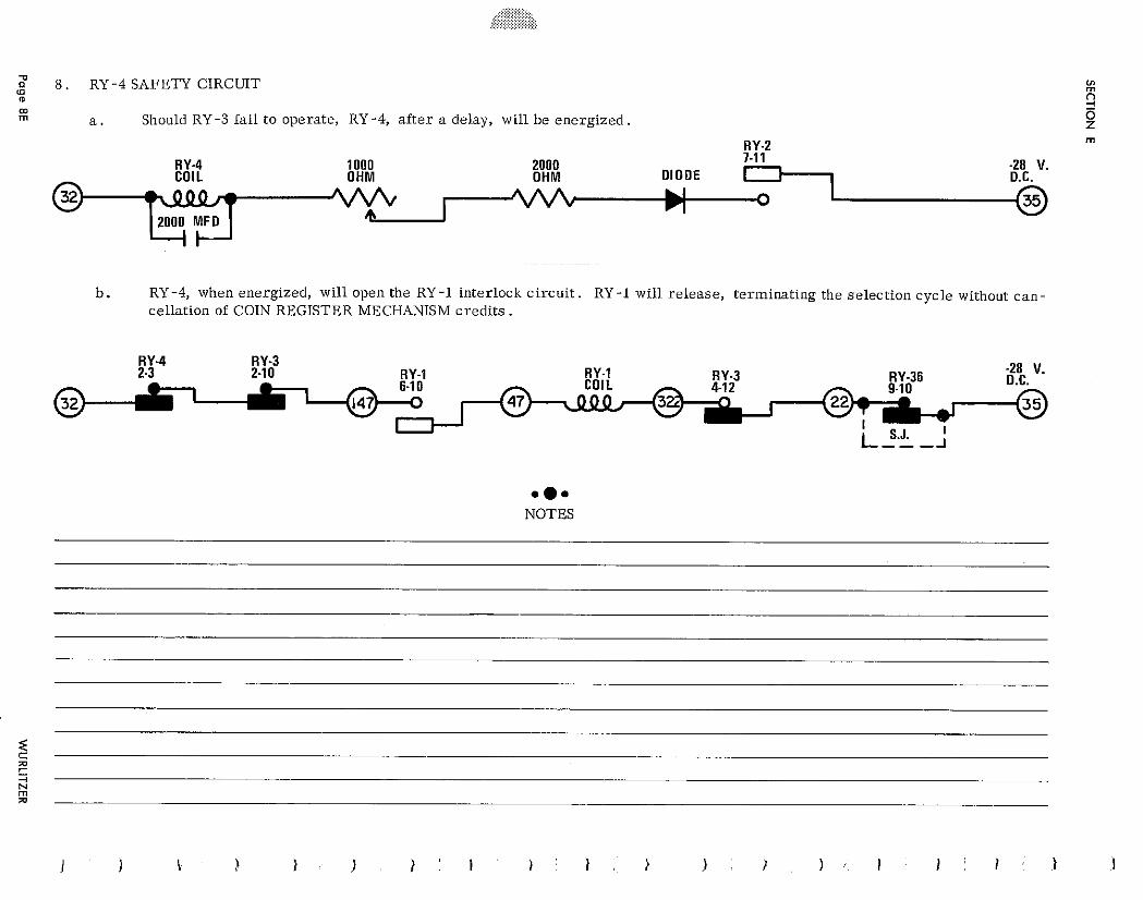
8. RY -4 SAFETY CIRCUIT 0 m m rn a . Should RY -3 fail to operate, RY -4, a f ter a delay, will be energized,
1000 2000 RY.4 2 8 V. COIL O H M O H M D IODE O.C.
I L I rl
b . RY-4, when energized, will open the RY-1 interlock circuit . RY-1 will release, terminating the selection cycle without can- cellation of COIN REGISTER MECHANISM credits .
.a. NOTES
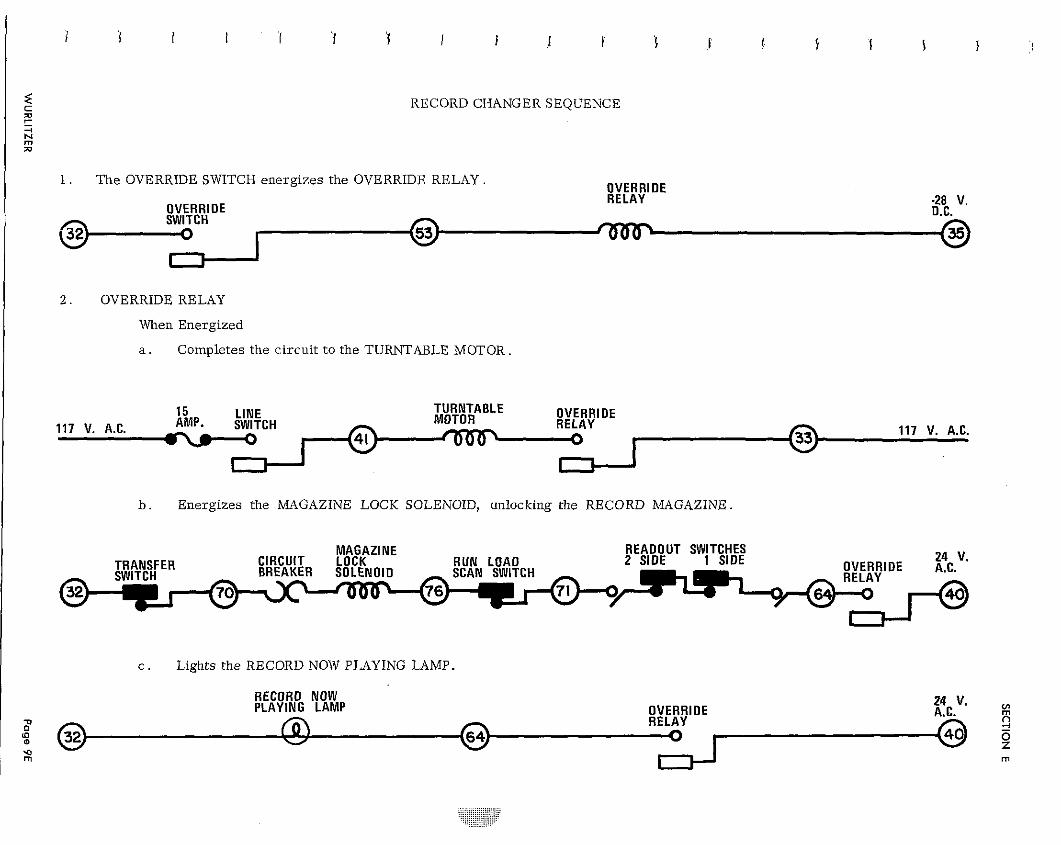
RECORD CHANGER SEQUENCE
1. The OVERRIDE SWITCH energizes the OVERRIDE RELAY. OVERRIDE RELAY
OVERRIDE -28 V. O.C.
I 2 . OVERRIDE RELAY
When Energized
a . Completes the circui t to the TURNTABLE MOTOR
15 LINE TURNTABLE MOTOR OVERRIDE
117 V. A.C. AMP. SWITCH RELAY 117 V. A.C.
b . Energizes the MAGAZINE LOCK SOLENOID, unlocking the RECORD MAGAZINE.
MAGAZINE READOUT SWITCHES CIRCUIT LOCK RUN LOAD 2 SIDE 1 SIDE 24 V. BREAKER SOLENOIO OVERRIDE A.C.
I c . Lights the RECORD NOW PLAYING LAMP.
RECORD NOW PLAYING LAMP OVERRIDE A.C. g 24 V.
RELAY 5 - 9
m rn I
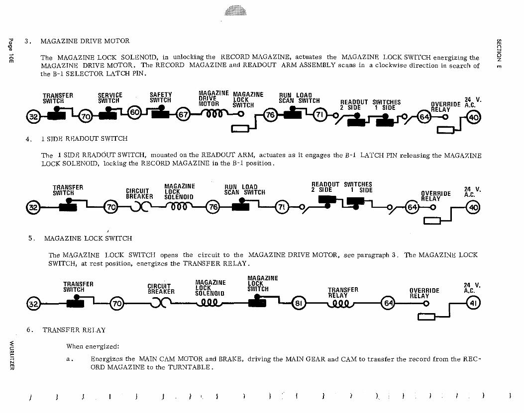
2 3 . MAGAZINE DRIVE MOTOR V) m U) m 2 A
% The MAGAZINE LOCK SOLENOID, in unlocking the RECORD MAGAZINE, actuates the MAGAZINE LOCK SWITCH energizing the 9 MAGAZINE DRIVE MOTOR. The RECORD MAGAZINE and READOUT ARM ASSEMBLY scans in a clockwise direction in s ea rch of the B-1 SELECTOR LATCH PIN.
TRANSFER SERVICE SAFETY Fi,$tzINE MAGAZINE RUN LOAD SWITCH SWITCH SWITCH LOCK SCAN SWITCH READOUT SWITCHES 24 V. MOTOR SWITCH OVERRIDE A.C.
4 . 1 SIDE READOUT SWITCH
The 1 SIDE READOUT SWITCH, mounted on the READOUT ARM, actuates a s i t engages the B-1 LATCH PIN releasing the MAGAZINE LOCK SOLENOID, locking the RECORD MAGAZINE in the B - l position.
TRANSFER MAGAZINE RUN LOAD READOUT SWITCHES SWITCH CIRCUIT LOCK SCAN SWITCH 2 SIDE 1 SIDE 24 V.
BREAKER SOLENOID OVERRIDE A.C.
76
5 . MAGAZINE LOCK SWITCH
The MAGAZINE LOCK SWITCH opens the circui t t o the MAGAZINE DRIVE MOTOR, s e e paragraph 3 . The MAGAZINE LOCK SWITCH, a t r e s t position, energizes the TRANSFER RELAY.
TRANSFER SWITCH
24 V. OVERRIDE RELAY
6 . TRANSFER RELAY
When energized:
a. Energizes the MAIN CAM MOTOR and BRAKE, driving the MAIN GEAR and CAM to t ransfer the record f rom the REC- ORD MAGAZINE to the TURNTABLE.
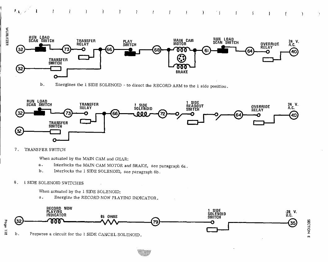
R U N LOAD SCAN SWITCH TRANSFER RUN LOAD SCAN SWITCH
BRAKE
b . Energizes the 1 SIDE SOLENOID - t o d i rec t the RECORD ARM t o the 1 s ide position.
RUN LOAD SCAN SWITCH TRANSFER 1 SIDE
1 SIDE OVERRIDE 24 V.
SOLENOID RELAY
TRANSFER SWITCH
7 . TRANSFER SWITCH
When actuated by the MAIN CAM and GEAR:
a . Interlocks the MAIN CAM MOTOR and BRAKE, s e e paragraph 6 a . b. Interlocks the 1 SIDE SOLENOID, s e e paragraph 6 b .
8 . 1 SIDE SOLENOID SWITCHES
When actuated by the 1 SIDE SOLENOID: a . Energize the RECORD NOW PLAYING INDICATOR.
RECORD NOW PLAYING 1 SIDE SOLENOID -28 V. INDICATOR 85 OHMS SWITCH D.C.
V) rn n
3 z
b . Prepares a c i rcu i t f o r the 1 SIDE CANCEL SOLENOID. rn
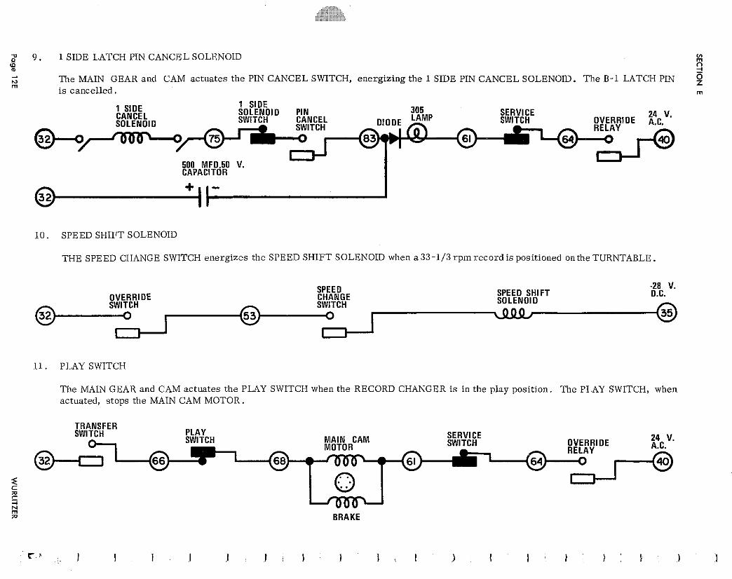
9 . 1 SIDE LATCH PIN CANCEL SOLENOID 0
% (P
A
3 M m
The MAIN GEAR and CAM actuates the PIN CANCEL SWITCH, energizing the 1 SIDE PIN CANCEL SOLENOID. The B-1 LATCH PIN is cancelled. m
1 SIDE 1 SIDE CANCEL SOLENOID PIN 305 SERVICE
SWITCH CANCEL SWITCH 24 V.
SOLENOID OVERRIDE A.C. RELAY 61
500 MFD.50 V. CAPACITOR
1 0 . SPEED SHIFT SOLENOID
THE SPEED CHANGE SWITCH energizes the SPEED SHIFT SOLENOID when a 33-1/3 r p m record is positioned on the TURNTABLE.
SPEED -28 V. OVERRIDE CHANGE SPEED SHIFT D.C.
SWITCH SOLENOID
11. PLAY SWITCH
The MAIN GEAR and CAM actuates the PLAY SWITCH when the RECORD CHANGER i s in the play position. The PLAY SWITCH, when actuated, stops the MAIN CAM MOTOR.
TRANSFER SWITCH PLAY
SWITCH M A I N CAM SERVICE SWITCH OVERRIDE 24 V.
MOTOR RELAY
61
s C 5 !+! w BRAKE
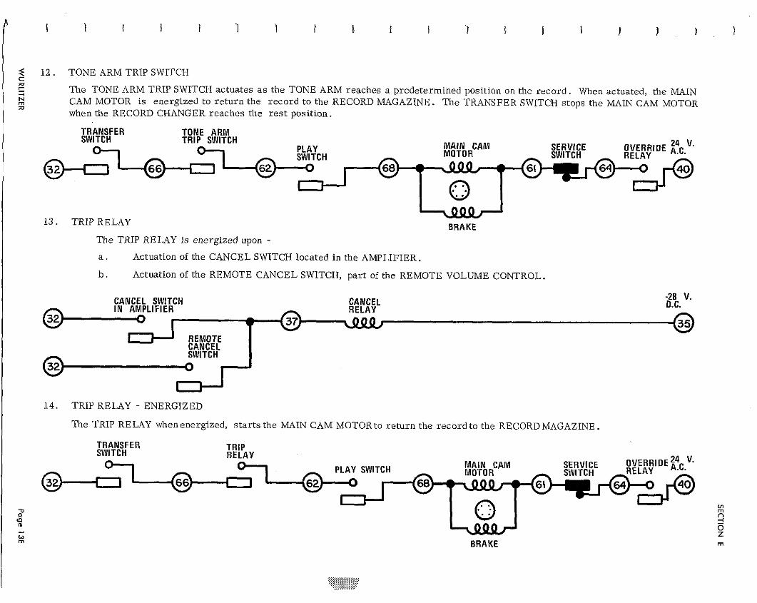
< 1 2 . TONE ARM TRIP SWITCH C 71 1 -. The TONE ARM TRIP SWITCH actuates a s the TONE ARM reaches a predetermined position on the r e c o r d . When actuated, the MAIN N m a
CAM MOTOR is energized t o r e t u r n the r eco rd t o the RECORD MAGAZINE. T h e TRANSFER SWITCH stops the MAIN CAM MOTOR when the RECORD CHANGER reaches the r e s t posi t ion.
TRANSFER TONE A R M SWITCH TRIP SWITCH
M A I N CAM SERVICE 24 V. MOTOR
OVERRIDE A,C, SWITCH RELAY
61
13. TRIP RELAY BRAKE The TRIP RELAY i s energized upon - a . Actuation of the CANCEL SWITCH located in the AMPLIFIER.
b . Actuation of t he REMOTE CANCEL SWITCH, pa r t of the REMOTE VOLUME CONTROL.
CANCEL SWITCH CANCEL -28 V. I N AMPLIFIER O.C.
I
REMOTE CANCEL SWITCH
14. TRIP RELAY - ENERGIZED
The TRIP RELAY when energized, s t a r t s the MAIN CAM MOTOR to r e tu rn the r eco rd to the RECORD MAGAZINE.
TRANSFER SWITCH TRIP
RELAY M A l N CAM OVERRIDE i4c,V. MOTOR SWITCH
2 n % 2 - 0 <. z
BRAKE rn
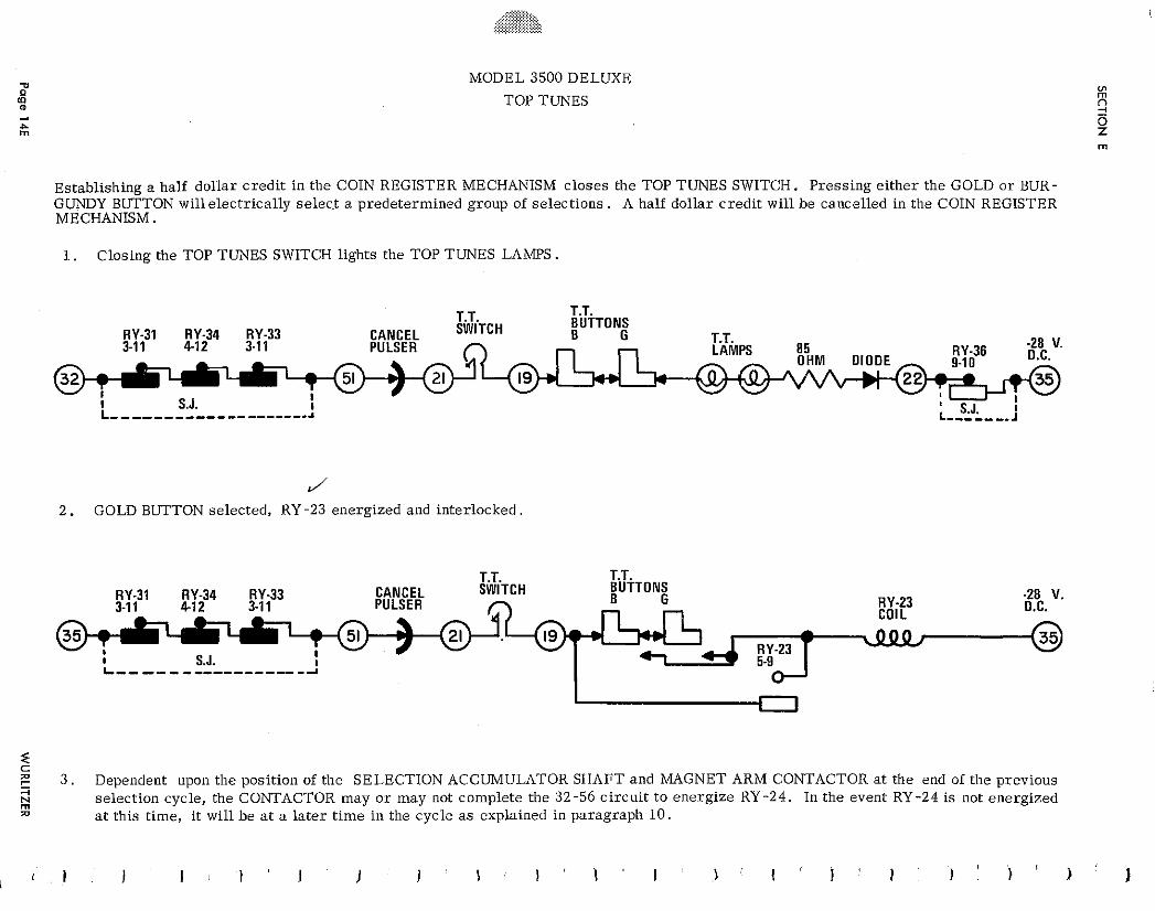
MODEL 3500 DELUXE
TOP TUNES
Establishing a half dol lar c r ed i t in the COIN REGISTER MECHANISM c loses the TOP TUNES SWITCH. Press ing e i ther the GOLD o r BUR- GUNDY BUTTON wil le lectr ical ly se1ec.t a predetermined group of select ions. A half dol lar c r ed i t will b e cancelled in the COIN REGISTER MECHANISM.
1. Closing the TOP TUNES SWITCH lights the TOP TUNES LAMPS.
J 2 . GOLD BUTTON selected, RY -23 energized and inter locked.
T.T. T.T. RY-31 RY-34 RY-33 CANCEL SWITCH BUTTONS
PULSER RY-23 -28 V.
3-1 1 4 1 2 3-1 1 COIL O.C.
RY-23 I S.J. I L-- -- - ---------- -A
i C
3 . Dependent upon the position of the SELECTION ACCUMULATOR SHAFT and MAGNET ARM CONTACTOR a t the end of the previous 4 N rn
select ion cycle, the CONTACTOR may o r may not complete the 32-56 c i r cu i t t o energ ize RY -24. In the event RY-24 i s not energized jil a t this t ime, i t will b e a t a l a t e r t ime in the cyc le as explained in paragraph 10.
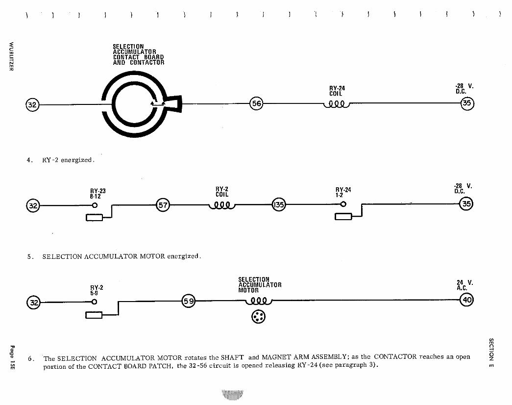
SELECT1 ON ACCUMULATOR CONTACT BOARD A N 0 CONTACTOR
%
RY-24 2 8 V. COIL D.C.
4 . RY -2 energized
RY-2 R Y -24 -28 V. RY-23 COIL 1-2 D.C. 8-12
5 . SELECTION ACCUMULATOR MOTOR energized.
SELECTION ACCUMULATOR 24 V. RY-2 MOTOR A.C. 5-9
. . z =' '0
6 . The SELECTION ACCUMULATOR MOTOR rotates the SHAFT and MAGNET ARM ASSEMBLY; a s the CONTACTOR reaches an open 9 01 rn portion of the CONTACT BOARD PATCH, the 32-56 circuit is opened releasing RY-24 (see paragraph 3) . rn
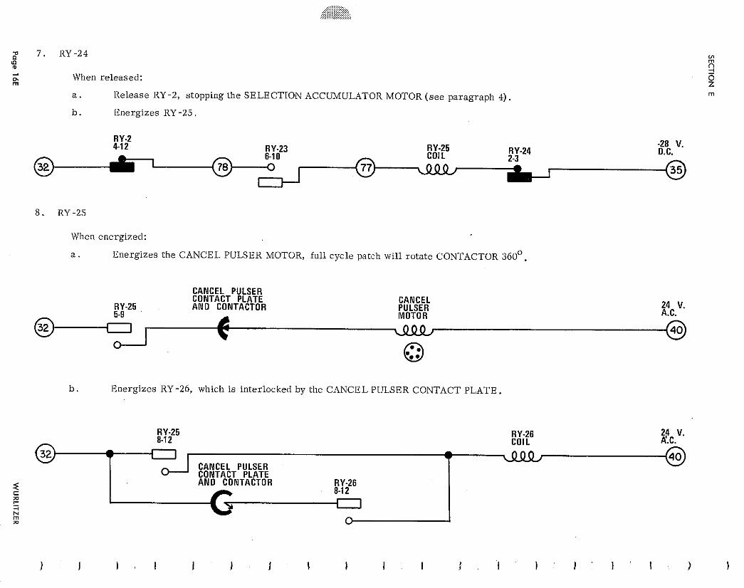
h rn
When released:
a . Release RY -2, stopping the SELECTION ACCUMULATOR MOTOR ( s e e paragraph 4).
b. Energizes RY -25.
RY.2 4-1 2 RY-23 RY-25 -28 V.
6-1 0 COIL RY-24 O.C. 2-3
When energized:
a . Energizes the CANCEL PULSER MOTOR, fu l l cycle patch will ro ta te CONTACTOR 360'.
CANCEL PULSER CONTACT PLATE CANCEL
RY-25 A N 0 CONTACTOR PULSER 24 V.
42 MOTOR A.C.
b . Energizes RY-26, which is interlocked by the CANCEL PULSER CONTACT PLATE
"- 8 c. LUIL
- I - < 000 - CANCEL PULSER
0----' CONTACT PLATE < A N 0 CONTACTOR RY-26 5 - 8-1 2
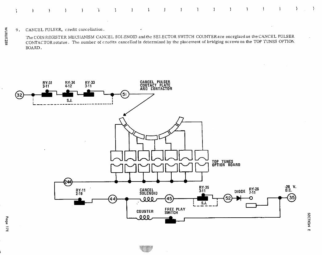
9 . CANCEL PULSER, c red i t cancel la t ion. C m 1 3 N
The COIN REGISTER MECHANISM CANCEL SOLENOID and the SELECTOR SWITCH COUNTERare energized a s the CANCEL PULSER m rn
CONTACTORrotates . T h e number of c red i t s cancelled i s determined by the placement of bridging s c r e w s on the TOP TUNES OPTION
BOARD.
w RY-35 RY.26 -28 V.
RY-11 CANCEL 3-1 1 DIODE 7-11 D.C. - COUNTER FREE PLAY
SWITCH
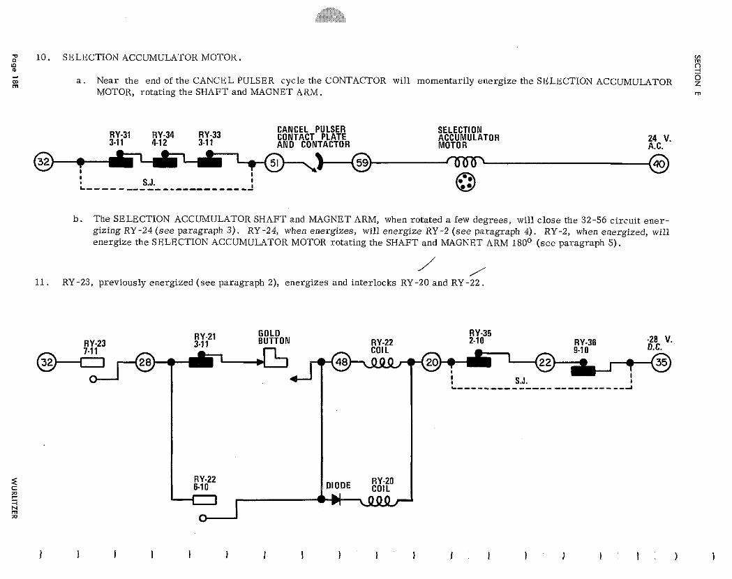
10 . SELECTION ACCUMULATOR MOTOR. L(1
% a - m 0 m
a . Near the end of t he CANCEL PULSER cyc le the CONTACTOR wil l momentar i ly energ ize the SELECTION ACCUMULATOR MOTOR, rotating the SHAFT and MAGNET ARM. m
RY.31 RY-34 RY-33 CANCEL PULSER SELECTION
3-1 1 41 2 3-1 1 CONTACT PLATE ACCUMULATOR AND CONTACTOR
24 V. MOTOR A.C.
I I
S.J. I L ---------------------- A
b. T h e SELECTION ACCUMULATOR SHAFT and MAGNET ARM, when rotated a few degrees , will c l o se the 32-56 c i rcu i t e n e r - gizing RY -24 ( s e e paragraph 3). RY -24, when energ izes , will energ ize RY -2 ( s e e paragraph 4). RY -2, when energized, will energize the SELECTION ACCUMULATOR MOTOR rotat ing the SHAFT and MAGNET ARM 180° ( s e e paragraph 5).
r
11. RY -23, previously energized ( s e e paragraph 2), energ izes and inter locks RY -20 and RY -22.
RY-21 GOLD RY-35 RY.23 3-1 1 BUTTON RY-22 2-1 0 RY.36 -28 V.
O.C. @-F,!,J@-4 T I I
RY-22 6-1 0
I Fl
RY-20 DIODE COIL
r U
c ----- ---- ----- --------- --2
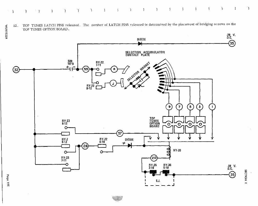
12 . TOP TUNES LATCH PINS r e l e a s e d . T h e number of LATCH PINS r e l e a s e d i s de te rmined by the placement of br idging s c r e w s on the C TOP TUNES OPTION BOARD.
-28 V. D IODE D.C.
1 U r l
SELECTION ACCUMULATOR CONTACT PLATE
RY-35 RY-36
VI rn
2 t S.J. I P 1 rn , - - - - J
1 3 . CYCLE TERMINATION. 0 (D
h) 0
The TOP TUNES selection cycle is terminated in the following manner: m
a . RY-23 is released a s the CANCEL PULSER CONTACTOR opens the 21 circui t
b . RY-25 i s released a s the 77-78 circui t is opend when RY-23 re leases
c . RY-26 i s released when the interlock circui t is opened as the CANCEL PULSER CONTACTOR reaches the r e s t position.
d . RY -24 is released when the SELECTION ACCUMULATOR SHAFT and MAGNET ARM CONTACTOR opens the 32-56 c i r ~ u i t .
e . RY -2 re leases as RY -24 opens the 135 c i rcu i t .
f . The SELECTION ACCUMULATOR MOTOR circui t is opened by the re lease of RY-2.
g. RY -20 and RY -21 re lease when RY -2 opens the 32-28 c i rcu i t .
e NOTES
TROUBLE SHOOTING
Page 1F
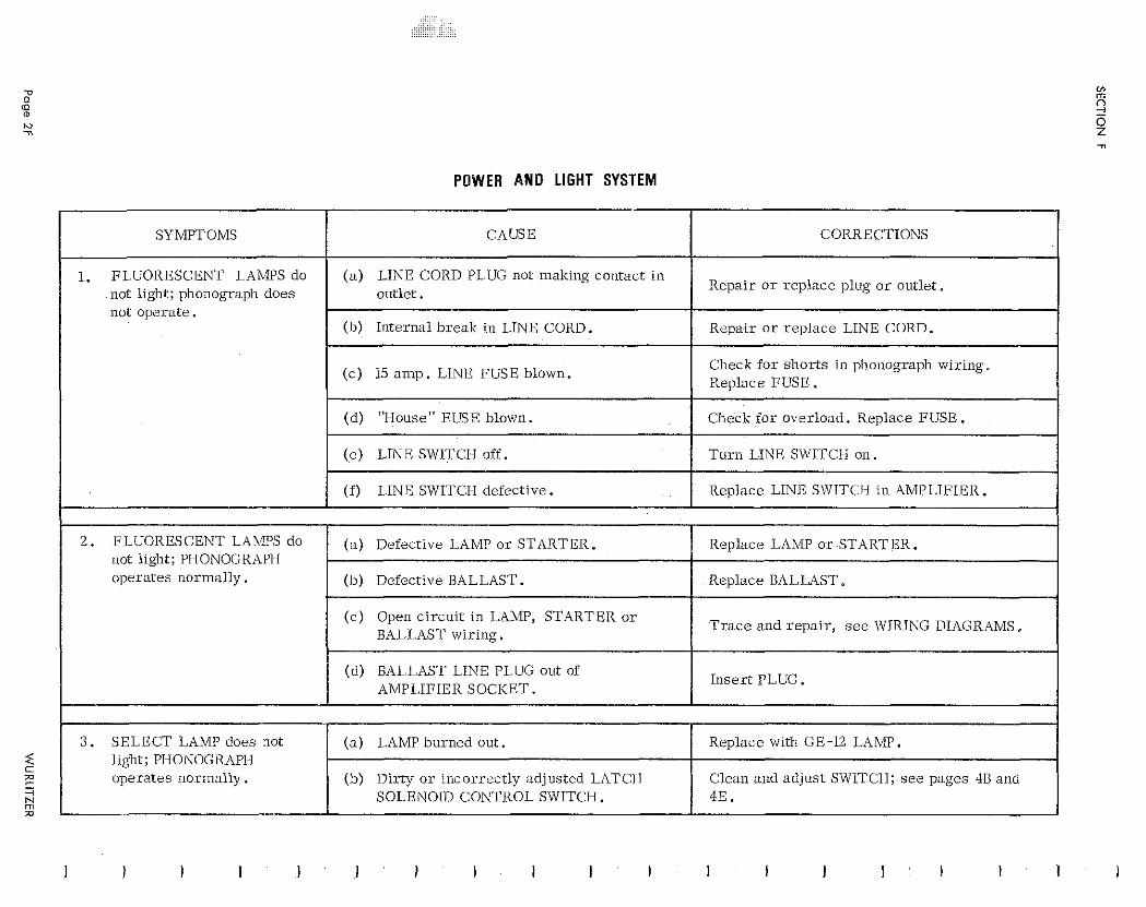
POWER AND LIGHT SYSTEM
SYMPTOMS CORRECTIONS
Repa i r o r rep lace plug o r outlet . not l ight; phonograph does not opera te .
(b) Internal b reak in LINE CORD. Repa i r o r r ep l ace LINE CORD.
Check f o r sho r t s i n phonograph wir ing. (c ) 15 a m p . LINE FUSE blown.
(d) "House" FUSE blown. Check f o r overload. Replace FUSE.
( e ) LINE SWITCH off. T u r n LINE SWITCH on.
not l ight; PHONOGRAPH opera tes ilormally .
3 . SELECT LAMP does not l ight; PIlONOGRhPH opera tes normal ly .
(b) Defective BALLAST.
(c ) Open c i rcu i t in LAMP, STARTER o r BALLAST wir ing.
(d) BALLAST LINE PLUG out of AMPLIFIER SOCKET.
( a ) LAMP burned out .
(b) Diriy o r incorrect ly adjusted LATCH SO1.ENOID CONTROL SWITCH.
Replace LAMP o r -STARTER.
Replace BALLAST.
T r a c e and r epa i r , s e e WIRING DIAGRAMS.
In se r t PLUG.
Replace with GE-12 LAMP.
Clean and adjust SWITCH; s e e pages 48 and 4E.
J
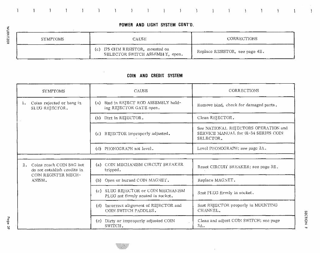
< POWER AND LIGHT SYSTEM CONT'O. C e - + F;I a
COIN AND CREDIT SYSTEM
CORRECTIONS
Replace RESISTOR, see page 413.
J
SYMPTOMS CAUSE
(c ) 175 OI-IM RESISTOR, mounted on SELECTOR SWITCH ASSEMBLY, open.
1
CORRECTIONS
Remove bind, check f o r damaged p a r t s .
Clean REJECTOR.
See NATIONAL REJECTORS OPERATION and SERVICE MANUAL f o r 01-34 SERIES COIN SELECTOR. - Level PHONOGKAPI-I; s e e page 2A.
Reset CIRCUIT BREAKER; s e e page 3E.
Replace MAGNET.
Seat PLUG f i rmly in socke t .
Seat REJECTOR properly in MOUNTING CI-IANNEL.
Clean and adjust COIN SWITCH; see page 311.
SYMPTOMS
1. Coins re jec ted o r hang i n SLUG REJECTOR.
2 . Coins reach COIN BAG but do not es tabl ish c red i t s i n COIN REGISTER MECM- ANISM.
CAUSE
(a ) Bind i n REJECT ROD ASSEMBLY hold- ing REJECTOR GATE open.
(b) Di r t i n REJECTOR.
(c ) REJECTOR improper ly adjusted.
(d) PHODJOGRAPI-I not level .
( a ) COIN MECHANISM CIRCUIT BREAKER t r ipped .
(b) Open o r burned COIN MAGNET.
(c ) SLUG REJECTOR o r COIN MECI-IANISM PLUG not f i rm ly s ea t ed in socket .
(d) Incor rec t a l ignment of REJECTOR and COIN SWITCH PADDLES.
(e ) Dir ty o r improper ly adjusted COIN SWITCH.
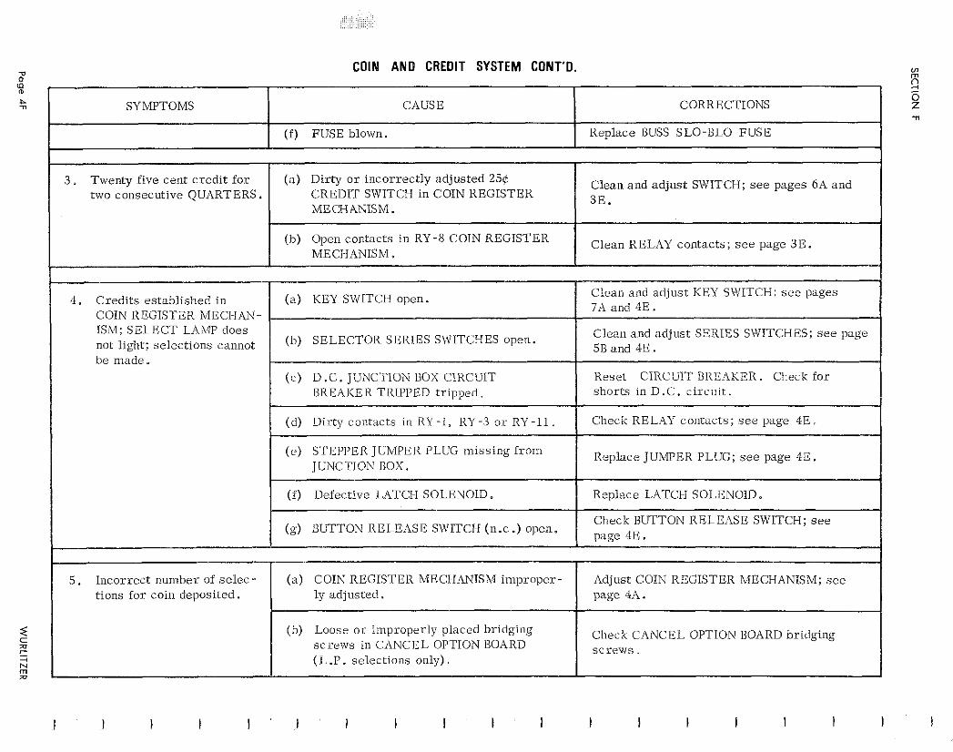
COIN AND CREDIT SYSTEM CONT'D.
SYMPTOMS CAUSE CORRECTIONS
Clean and ad jus t SWITCH; see pages 6A and two consecutive QUARTERS. CREDIT SWITCH in COIN REGISTER
(b) Open contacts in RY -8 COIN REGISTER Clean RELAY contacts ; s e e page 3E. MECI-IANISM ,
COIN REGISTER MECIIAN- ISM; SELECT LAMP does
(b) SELECTOR SERIES S\VITCIIES open. C l e m and adjust SERIES SVJITCHES; see page not light; select ions cannot
CUIT BREAKER. Check for
Replace JUMPER PLUG; see page 4E.
tions f o r coin deposited.
(h) Loose o r improperly placed bridging Check CANCEL OPTION BOARD bridging s c r e ~ v s in CANCEL OPTION BOARD ( L .P. select ions only).
s c r e w s .
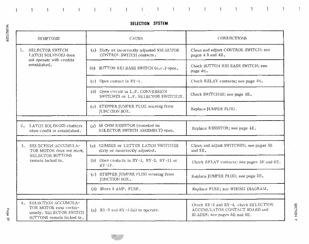
SELECTION SYSTEM
1. SELECTOR SWITCH (a) Dirty o r incorrect ly adjusted SELECTOR LATCH SOLENOID does CONTROL SWITCH contacts . not operate with c red i t s established.
Check SWITCI-1%; s e e page 4E.
Replace JUMPER PLUG.
TOR MOTOR does not s t a r t , SELECTOR BUTTONS remain locked in.
Replace JUMPER PLUG; see page 5E .
(a) RY -3 and RY-4 fai l to opera te . ACCUh4ULATOR CONTACT BOARD and uously. SELECTOR STVITCIH BLADES; s e e pages 6E and 8 E . BUTTONS remain locked in .
I I
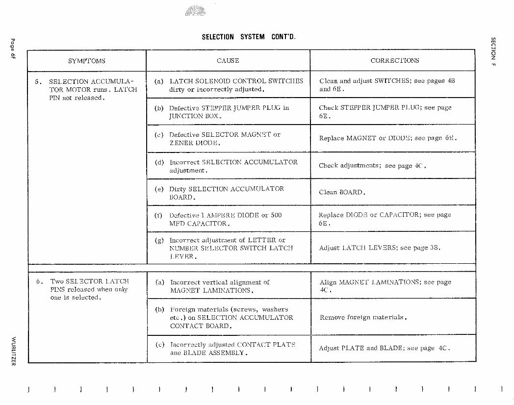
SELECTION SYSTEM CONT'D.
I SYMPTOMS I CAUSE I CORRECTIONS I
I (b) Defective STEPPER I U h P E R PLUG in JUNCTION BOX.
5. SELECTION ACCUMULA- TOR MOTOR r u n s . LATCH PIN not r e l e a sed .
Check STEPPER JUMPER PLUG; see page 6 E . I
I (c ) Defective SELECTOR MAGNET o r ZENER DIODE.
( a ) LATCH SOLENOID CONTROL SWITCHES d i r ty o r incor rec t ly adjusted.
Replace MAGNET o r DIODE; see page 6 E . I
Clean and ad jus t SWlTCFIES; see pages 48 and 6 E .
(d) Incor rec t SELECTION ACCUMULATOR Check a d j u s t n ~ e n t s ; see page 4C adjustment .
(e ) Dir ty SELECTION ACCUMULATOR BOARD.
Clean BOARD.
(f) Dciectlve 1 AhlPERE DIODE o r 500 MFD CAPACITOR.
(g) Incor rec t ad jus tme~r t of LETTER o r NUMBER SFLECTOR SN'ITCI-I L,iTCII LEVER.
Replace DIODE o r CAPACITOR; s e e page 6 E .
Adjust LATCH LEVERS; s e e page 3B.
6 . Two SELECTOR 1-IITCI-I (a ) Incor rec t ve r t i c a l alignment of PINS re leased when only
i MAGNET LAMINATIONS.
one is se lec ted .
(b) Fore ign ma te r i a l s ( s c r ews , washe r s e tc .) on SELECTION ACCUhllULrlTOR CONTACT BOARD.
(c) Iilcorrectly adjusted CONTACT PLATE and BLADE ASSEMBLY.
Align MAGXET LAMLNf1TIONS; s e e page I X .
R e ~ n o v e foreign ma te r i a l s .
Adjust PLATE and BLADE; s e e page 4C.
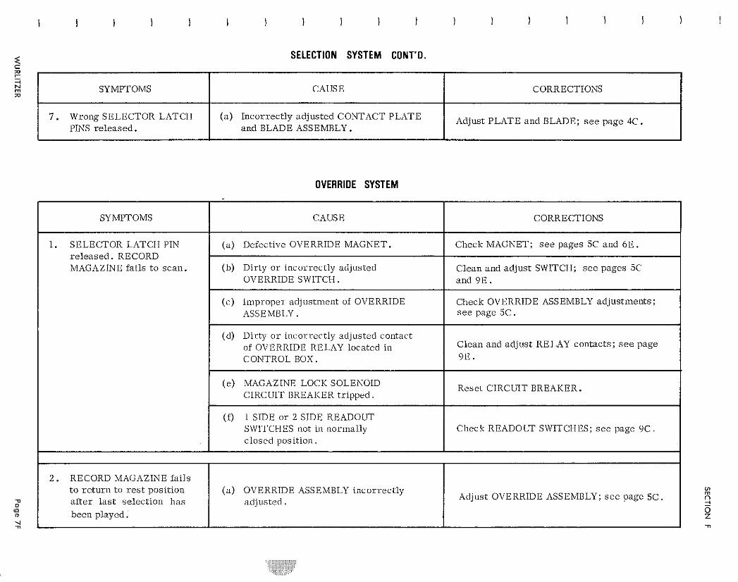
SELECTION SYSTEM CONT'D.
OVERRIDE SYSTEM
SYMPTOMS
7 . Wrong SELECTOR LATCH PINS r e l e a s e d .
CAUSE
( a ) Incor rec t ly ad jus ted CONTACT PLATE a n d BLADE ASSEMBLY.
SYMPTOMS
1. SELECTOR LATCH PIN r e l e a s e d . RECORD MAGAZINE fa i l s t o s c a n .
2 . RECORD MAGAZINE fa i l s t o r e t u r n t o rest posi t ion a f t e r l a s t se lec t ion h a s been played.
1
CORRECTIONS
Adjust PLATE a n d BLADE; see page 4C.
CAUSE
( a ) Defective OVERRIDE MAGNET.
(b ) Di r ty o r incor rec t ly adjusted OVERRIDE SWITCH.
( c ) I ~ n p r o p e r adjustment of OVERRIDE ASSEMBLY.
(d) Di r ty o r incor rec t ly adjusted contact of OVERRIDE RELAY located in CONTROL BOX.
( e ) MAGAZINE LOCK SOLENOID CIRCUIT BREAKER t r i p p e d .
(f) 1 SIDE o r 2 SIDE READOUT SWITCHES not in l lormally c losed posi t ion.
( a ) OVERRIDE ASSEMBLY i n c o r r e c t l y a d j u s t e d .
CORRECTIONS
Check MAGNET; see pages 5C a n d 6 E .
C l e a n a n d ad jus t SWITCH; see pages 5C a n d 9 E .
Check OVERRIDE ASSEMBLY ad jus tments ; s e e page 5 C .
C l e a n a n d ad jus t RELAY contacts ; see page 9 E .
Rese t CIRCUIT BREAKER.
Check R E A D O W SWITCHES; s e e page 9 C .
Adjust OVERRIDE ASSEMBLY; s e e page 5C.
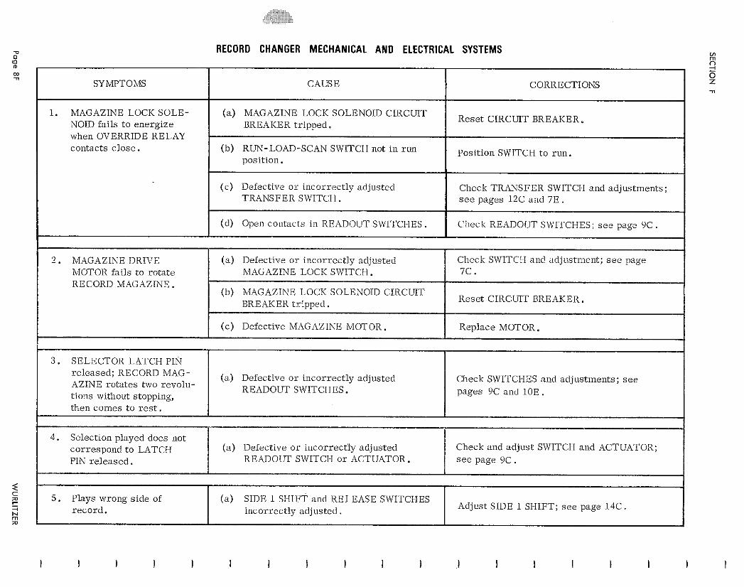
RECORD CHANGER MECHANICAL AND ELECTRICAL SYSTEMS
NOID fai ls t o energ ize Rese t CIRCUIT BREAKER.
when OVERRIDE RELAY contacts c lose .
Position SWITCH t o run .
( c ) Defective o r incorrect ly adjusted TRANSFER SWITCH.
2 . MAGAZINE DRIVE ( a ) Defective o r incor rec t ly adjusted Check SWITCI-I and adjustment; s e e page MOTOR fa i l s t o ro ta te MAGAZINE LOCK SWITCH. RECORD MAGAZINE.
re leased ; RECORD MAG- ( a ) Defective o r incor rec t ly adjusted Check SWITCHES and adjustments; s e e
READOUT SWITCHES. pages YC and 10E .
Adjust SIDE 1 SHIFT; s e e page 14C.
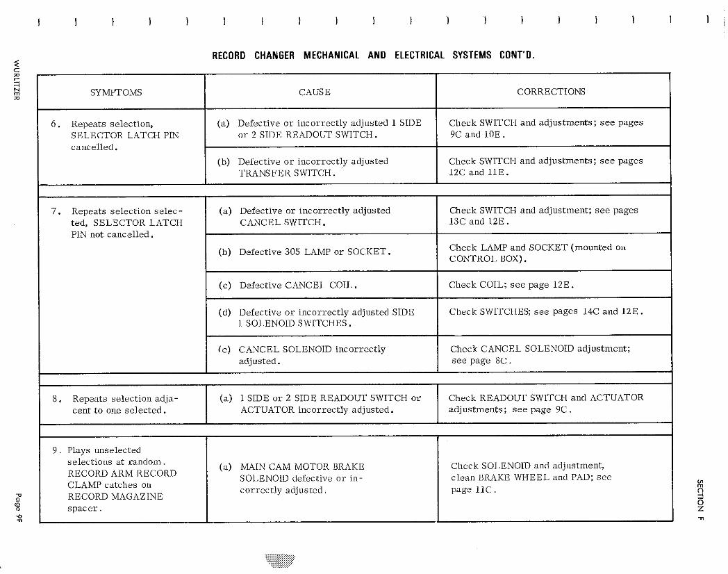
RECORD CHANGER MECHANICAL A N D ELECTRICAL SYSTEMS CONT'D.
CORRECTIONS -
Check SWITCH and adjustments; see pages 9C and 1 0 E .
Check SWITCI-I and adjustments; see pages 12C and 11E .
Check SWITCH and adjustment; see pages 13C and 1 2 E .
Check LAMP and SOCKET (mounted on CONTROL BOX).
Check COIL; s e e page 12E .
Check SWITCHES; s e e pages 14C and 1 2 E .
Check CANCEL SOLENOID adjustment; s e e page 8 C .
Check READOUT SWITCH and ACTUATOR adjustments; s e e page 9C .
Check SOLENOID and adjustment, c lean BRAKE WIHEEL and PAD; s e e page 1 1 C .
SYMPTOMS
6 . Repeats selection, SELECTOR LATCH PIN cancel led.
7 . Repeats select ion s e l ec - ted, SELECTOR LATCH PIN not cancel led.
8. Repeats select ion ad ja - cent t o one se lec ted .
9 . Plays unselected select ions a t random. RECORDARMRECORD CLAMP c a t c l ~ e s on RECORD MAGAZINE s p a c e r .
CAUSE
(a ) Defective o r incorrect ly adjusted 1 SIDE o r 2 SIDE READOLTI' SWITCH.
(b) Defective o r incorrect ly adjusted TRANSFER SWITCH.
( a ) Defective o r incor rec t ly adjusted CANCEL SWITCH.
(b) Defective 305 LAMP o r SOCKET.
(c ) Defective CANCEL COIL.
(d) Defective o r incorrect ly adjusted SIDE 1 SOLENOID SWITCHES.
( e ) CANCEL SOLENOID incorrect ly adjusted.
(a ) 1 SIDE o r 2 SIDE READOUT SWITCH o r ACTUATOR incorrect ly adjusted.
(a) MAIN CAM MOTOR BRAKE SOLENOID defective o r in- cor rec t ly ad jus ted .
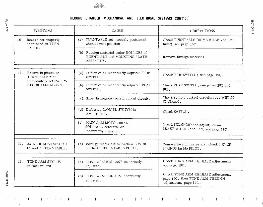
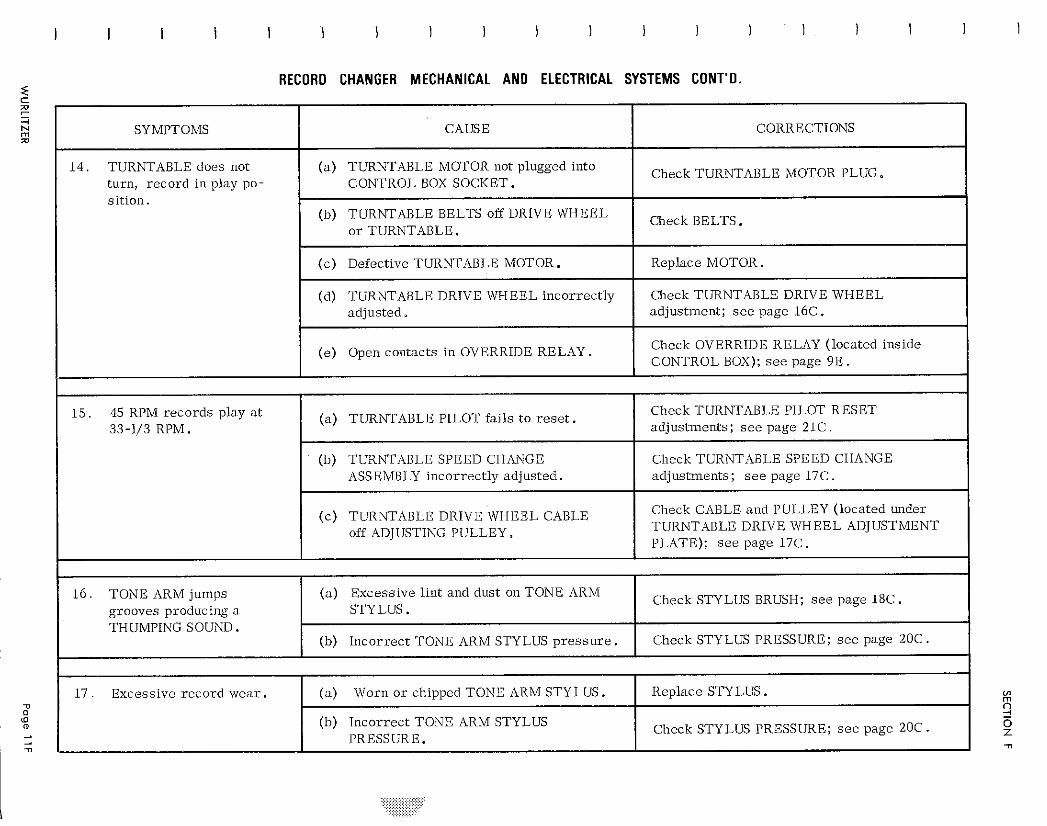
RECORD CHANGER MECHANICAL AND ELECTRICAL SYSTEMS CONT'D. < C a
CORRECTIONS
Check TURNTABLE MOTOR PLUG*
Check BELTS.
Replace MOTOR.
Check TURNTABLE DRIVE WHEEL adjustment; s e e page 16C.
Check OVERRIDE RELAY (located inside CONTROL BOX); see page 9 E .
Check TURNTABLE PILOT RESET adjustments; s e e page 21C.
Check TURNTABLE SPEED CHANGE adjustments; s e e page 17C.
Check CABLE and PULLEY (located under TURNTABLE DRIVE WHEEL ADJUSTMENT PLATE); s e e page 17C.
Check STYLUS BRUSH; s e e page 18C.
Check STYLUS PRESSURE; see page 20C.
Replace STYLUS . Check STYLUS PRESSURE; s e e page 20C.
SYMPTOMS
14. TURNTABLE does not turn, record in play po- s i t ion.
1 5 . 45 RPM reco rds play a t 33-1/3 RPM .
16. TONE ARM jumps grooves producing a THUMPING SOUND.
1 7 . Excessive record wea r .
CAUSE
(a) TURNTABLE MOTOR not plugged into CONTROL BOX SOCKET.
(b) TURiWABLE BELTS off DRIVE WHEEL o r TURNTABLE.
( c ) Defective TURNTABLE MOTOR.
(d) TURNTABLE DRIVE WHEEL incorrect ly adjusted.
(e) Open contacts in OVERRIDE RELAY.
(a) TURNTABLE PILOT fails to r e s e t .
(b) TURhTABLE SPEED CHATVGE ASSEhtBLY incorrect ly adjusted.
(c) TURNTABLE DRIVE WHEEL CABLE off ADJUSTING PULLEY.
(a) Excessive lint and dust on TONE ARM STYLUS .
(b) Incorrect TONE ARM STYLUS p r e s s u r e .
(a) Worn o r chipped TONE ARM STYLUS . (b) Incorrect TONE ARM STYLUS
PRESSURE.
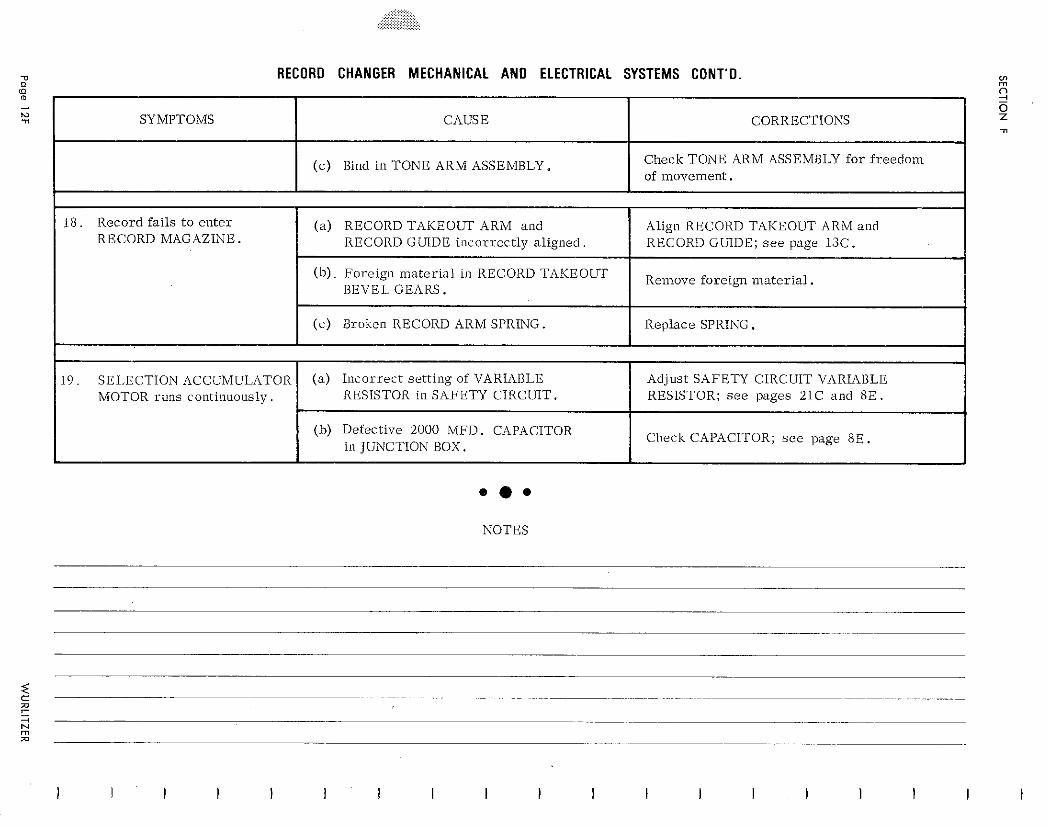
RECORD CHANGER MECHANICAL A N D ELECTRICAL SYSTEMS CONT'O.
... NOTES
SYMPTOMS
1 8 . Record fa i l s t o e n t e r RECORD MAGAZINE.
1 9 . SEI.ECTION ACCUMULATOR MOTOR runs colltilluously .
CAUSE
( c ) Bind in TONE ARM ASSEMBLY.
(a ) RECORD TAKEOUT ARM and RECORD GLIIDE i i lcorrect ly a l igned .
( h ) Fore ign m a t e r i a l in RECORD TAKEOUT BEVEL GEARS.
( c ) Broken RECORD ARM SPRING.
( a ) I n c o r r e c t se t t ing of VARIABLE RESISTOR in SAFETY CIRCUIT.
(b) Defective 2000 MFD. CAPACITOR in JUiVCTION BOX.
CORRECTIONS
Check TONE ARM ASSEMBLY f o r f r e e d o m of movement .
Align RECORD TAKEOUT ARM and RECORD GUIDE; s e e page 13C.
Relnove foreign material,
Replace SPRING.
Adjust SAFETY CIRCUIT VARIABLE RESISTOR; s e e pages 21C and 8 E .
Check CAPACITOR; s e e page 8 E .

ELECTRICAL AND SOUND SYSTEMS
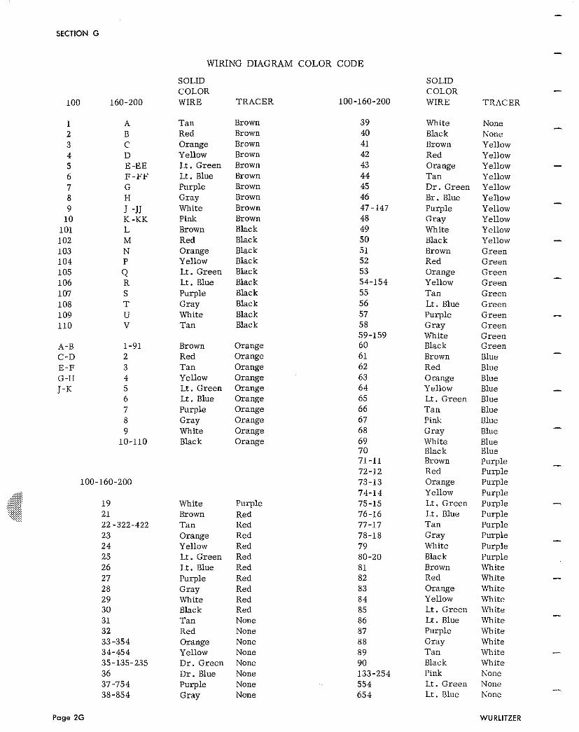
SECTION G
1 A 2 B 3 C 4 D 5 E-EE 6 F - F F 7 G 8 H 9 J -JJ
10 K -KK 101 L 102 M 103 N 104 P 105 Q 106 R 107 S 108 T 109 U 110 v
A-B 1-91 C-D 2 E - F 3 G -H 4 J-K 5
6 7 8 9
10-110
WIRING DIAGRAM COLOR
SOLID COLOR WIRE TRACER
Tan Brown Red Brown Orange Brown Yellow Brown Lt. Green Brown Lt . Blue Brown Purple Brown Gray Brown White Brown Pink Brown Brown Black Red Black Orange Black Yellow Black Lt. Green Black Lt. Blue Black Purple Black Gray Black White Black Tan Black
Brown Orange Red Orange Tan Orange Yellow Orange Lt. Green Orange Lt. Blue Orange Purple Orange Gray Orange White Orange Black Orange
White Purple Brown Red Tan Red Orange Red Yellow Red Lt. Green Red Lt. Blue Red Purple Red Gray Red White Red Black Red Tan None Red None Orange None Yellow None Dr . Green None D r . Blue None Purple None Gray None
CODE
SOLID COLOR WIRE
White Black Brown Red Orange Tan D r . Green Br . Blue Purple Gray White Black Brown Red Orange Yellow Tan Lt . Blue Purple Gray White Black Brown Red Orange Yellow Lt. Green Tan Pink Gray White Black Brown Red Orange Yellow Lt . Green Lt. Blue Tan Gray White Black Brown Red Orange Yellow Lt . Green Lt. Blue Purple Gray T a n Black Pink Lt. Green Lt . Blue
TRACER
None None Yellow Yellow Yellow Yellow Yellow Yellow Yellow Yellow Yellow Yellow Green Green Green Green Green Green Green Green Green Green Blue Blue Blue Blue Blue Blue Blue Blue Blue Blue Purple Purple Purple Purple Purple Purple Purple Purple Purple Purple White White White White White White White White White White None None None
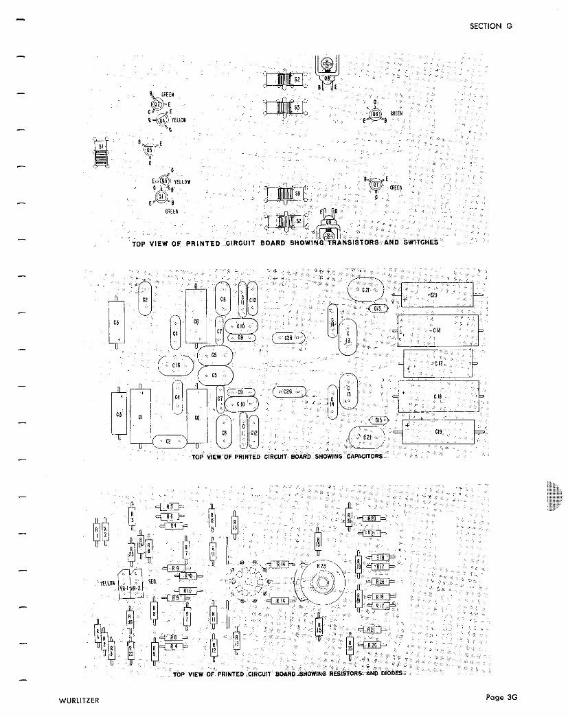
WURLITZER Page 3G
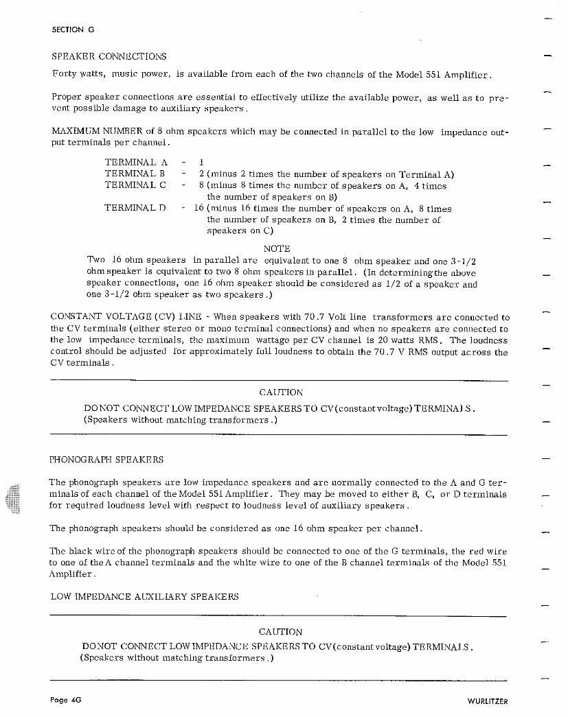
SECTION G
SPEAKER CONNECTIONS
For ty va t t s , music power, is available f r o m each of the two channels of the Model 551 Amplifier
Proper speake r connections a r e essen t ia l to effectively utilize the avai lable power, as well a s t o p r e - vent possible damage t o auxi l iary s p e a k e r s .
MAXIMUM NUMBER of 8 ohm speake r s which may be connected in para l le l t o the low impedance out- put t e rmina ls pe r channel .
TERMINAL A - 1 TERMINAL B - 2 (minus 2 t imes the number of speake r s on Te rmina l A) TERMINAL C - 8 (minus 8 t imes the number of speake r s on A, 4 t imes
the number of speake r s on B) TERMINAL D - 16 (minus 16 t imes the number of speake r s on A, 8 t imes
the number of speake r s on B, 2 t imes the number of speakers on C)
NOTE Two 16 ohm speake r s in para l le l a r e equivalent t o one 8 ohm speake r and one 3-1/2 ohmspeake r i s equivalent t o two 8 ohm speake r s in pa r a l l e l . (In de te rmin ing the above speake r connections, one 16 ohm speake r should be considered as 1/2 of a speake r and one 3-1/2 ohm speake r as two speake r s .)
CONSTANT VOLTAGE (CV) LINE - When speake r s with 70 .7 Volt l ine t r an s fo rmer s are connected to the CV te rmina ls (e i ther s t e r e o o r mono te rmina l connections) and when no speake r s a r e connected t o the low impedance te rmina ls , the maximum wattage p e r CV channel is 20 watts RMS. T h e loudness control should be adjusted f o r approximately ful l loudness t o obtain the 70 .7 V RMS output a c r o s s the CV t e r m i n a l s .
DONOT CONNECT LOW IMPEDANCE SPEAKERS T O CV(constantvo1tage) TERMINALS. (Speakers without matching t r an s fo rmer s .)
PHONOGRAPH SPEAKERS
,.; :.?> ....., T h e phonograph speakers are low impedance speake r s and a r e normally connected t o the A and G t e r -
..... ...... ...... ...... ...... .,.......::. ...... .:.:. . . . . . . . ..,.,.,.,.... : minals of each channel of the Model 551 Amplif ier . They may be moved t o e i t he r B, C, o r D t e rmina l s
... :.:.:.:.. ..., . . . . +:.::::::: ... . .,. ......,. f o r required loudness l eve l with r e spec t t o loudness level of auxi l iary s p e a k e r s .
The phonograph speake r s should be considered as one 16 ohm speake r p e r channel .
The black wi reof the phonograph speake r s should be connected t o one of the G te rmina ls , the r e d w i r e to one of t heA channel t e rmina ls and the white w i r e to one of the B channel t e rmina ls of the Model 551 Amplif ier .
LOW IMPEDANCE AUXILIARY SPEAKERS
CAUTION
DONOT CONNECT LOW IMPEDANCE SPEAKERS T O CV(constant voltage) TERMINALS . (Speakers without matching t r an s fo rmer s .)
Page 4G WURLITZER
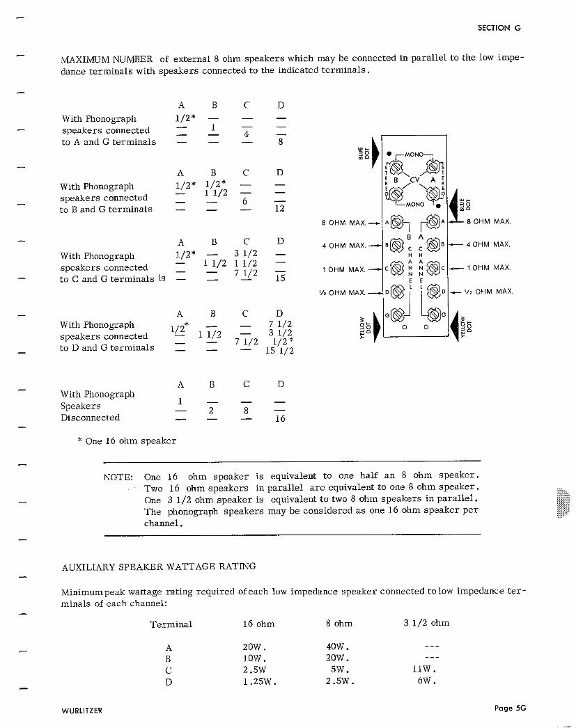
SECTION G
MAXIMUM NUMBER of external 8 ohm speakers which may be connected in parallel to the low impe- dance terminals with speakers connected to the indicated terminals.
A B C D With Phonograph 1/2* - - - - 1 - - speakers connected - - 4 - to A and G terminals - - - 8
A B C D With Phonograph 1/2* 1/2* - -
- 1 1/2 - - speakers connected - - - to B and G terminals - - - 12
A B C D With Phonograph 1/2* - 3 1/2 - - speakers connected 1 1/2 1 1/2 - - - to C and G terminals Ls - - 7 - 1/2 15
A B C D With Phonograph - 7 1/2 speakers connected I/"* 11/2 - 3 1/2 - - to D and G terminals - - 7 1/2 1 /2* - 15 1/2
A B C D With Phonograph
1 - - - Speakers - 2 8 - Disconnected - - - 16
* One 16 ohm speaker
NOTE: One 16 ohm speaker i s equivalent to one half a n 8 ohm speaker. Two 16 ohm speakers in parallel a r e equivalent to one 8 ohm speaker. One 3 1/2 ohm speaker is equivalent to two 8 ohm speakers in parallel. The phonograph speakers may be considered a s one 16 ohm speaker per channel.
1 . .
4 OHM MAX. - 0 QBc @ B
H H
1 OHM MAX. - C @ i i @C
E E
lv2 O H M MAX, o@J ; j @ D
AUXILIARY SPEAKER WATTAGE RATING
c 40HM MAX.
c 1 O H M MAX.
- O H M M A X
Minimumpeak wattage rating required of each low impedance speaker connected to low impedance t e r - minals of each channel:
Terminal 16 ohm 8 ohm 3 1/2 ohm
20W. 40W. - - - low. 20w. --- 2.5W 5W. 11W. 1.25W. 2.5W. 6W.
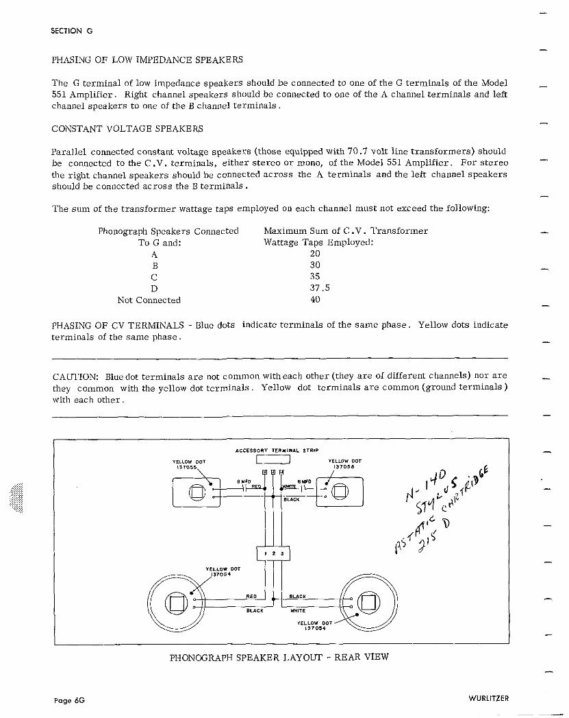
SECTION G
PHASING OF LOW IMPEDANCE SPEAKERS
The G terminal of low impedance speakers should be connected to one of the G terminals of the Model 551 Amplifier. Right channel speakers should be connected to one of the A channel terminals and left channel speakers to one of the B channel terminals.
CONSTANT VOLTAGE SPEAKERS
Parallel connected constant voltage speakers (those equipped with 70.7 volt line transformers) should be connected to the C .V. terminals, either s tereo o r mono, of the Model 551 Amplifier. For s tereo the right channel speakers should be connected across the A terminals and the left channel speakers should be connected across the B terminals.
The sum of the transformer wattage taps employed on each channel must not exceed the following:
Phonograph Speakers Connected Maximum Sum of C .V. Transformer To G and: Wattage Taps Employed:
A 20 B 30 C 35 D 37.5
Not Connected 40
PHASING OF CV TERMINALS - Blue dots indicate terminals of the same phase. Yellow dots indicate terminals of the same phase.
CAUTION: Bluedot terminals a r e not common witheach other (they a r e of different channels) nor a r e they common with the yellow dot terminals. Yellow dot terminals a r e common (ground terminals) with each other.
ACCESSORY TERMINAL STR1P
YELLOW DOT YELLOW DOT
Page 6G
PHONCGRAPH SPEAKER LAYOUT - REAR VIEW
WURLITZER
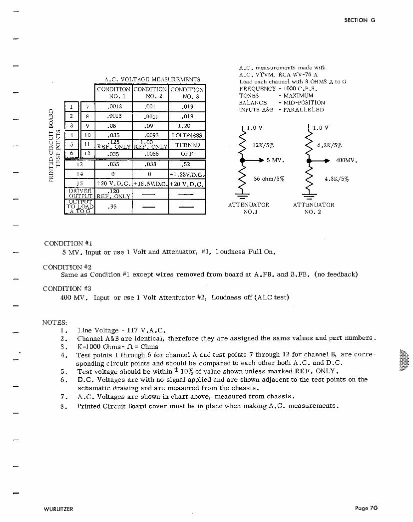
SECTION G
A .C. m e a s u r e m e n t s m a d e with
A.C. VOLTAGE MEASUREMENTS
T O LOAD
A.C. VTVM, RCA WV-76 A Load each channel with 8 OHMS A to G FREQUENCY - 1000 C.P.S. TONES - MAXIMUM BALANCE - MID-POSITION I N P W S A&B - PARALLELED
5 MV. 400MV.
56 ohm/5%
- - - - ATTEN UATOR ATTENUATOR
NO.1 NO. 2
CONDITION #1 - 5 MV. Input o r use 1 Volt and Attenuator, #1, Loudness Ful l On.
CONDITION #2
- Same a s Condition #1 except wires removed f rom board a t A.FB. and B.FB. (no feedback)
CONDITION #3 400 MV. Input o r use 1 Volt Attentuator #2, Loudness off (ALC tes t )
NOTES: - 1. 2. 3 .
- 4 .
Line Voltage - 117 V .A. C. Channel A&B a r e identical, therefore they a r e assigned the s a m e values and par t numbers. K=1000 Ohms - fl = Ohms ::.:-, ~ e s t points 1 through 6 for channel A and tes t points 7 through 12 for channel B, a r e c o r r e - :.:*.. .. .... ... ..:::,.... .:.:.:.:<.:. sponding circuit points and should be compared to each other both A .C. and D.C. $$$ . .........., ... ... .. Tes t voltage should be within t 10% of value shown unless marked REF. ONLY.
:p?
D.C. Voltages a r e with no signal applied and a r e shown adjacent to the t e s t points on the schematic drawing and a r e measured f rom the chass is . A .C. Voltages a r e shown in char t above, measured f rom chass is .
8. Printed Circuit Board cover must be in place when making A .C. measurements.
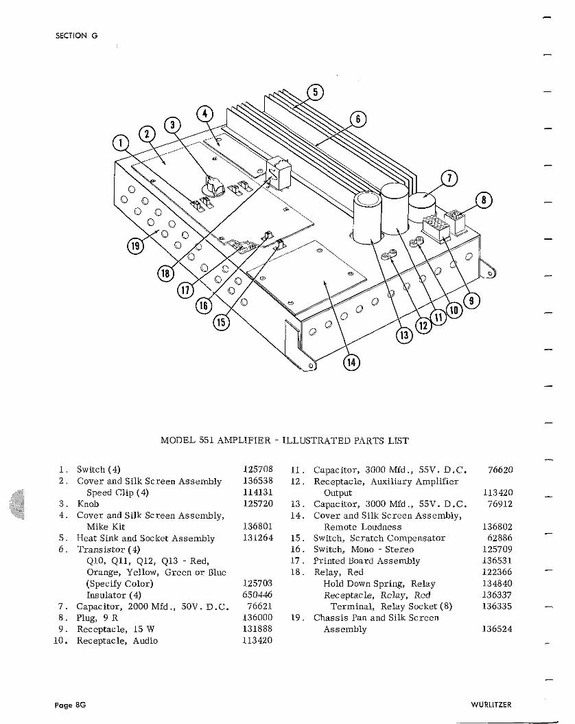
SECTION G
MODEL 551 AMPLIFIER -
Switch (4) Cover and Silk Screen Assembly
Speed Clip (4) Knob Cover and Silk Screen Assembly,
Mike Kit Heat Sink and Socket Assembly Trans is tor ( 4)
410, Qll, 412, 413 - Red, Orange, Yellow, Green o r Blue (Specify Color) Insulator (4)
Capacitor, 2000 Mfd ., 50V. D .C. Plug, 9 R Receptacle, 15 W Receptacle, Audio
ILLUSTRATED PARTS LIST
Capacitor, 3000 Mfd ., 55V. D.C. Receptacle, Auxiliary Amplifier
Output Capacitor, 3000 Mfd ., 55V. D .C. Cover and Silk Screen Assembly,
Remote Loudness Switch, Scratch Compensator Switch, Mono - Stereo Printed Board Assembly Relay, Red
Hold Down Spring, Relay Receptacle, Relay, Red
Terminal , Relay Socket (8) Chassis Pan and Silk Screen
Assembly
Page 8G WURLITZER
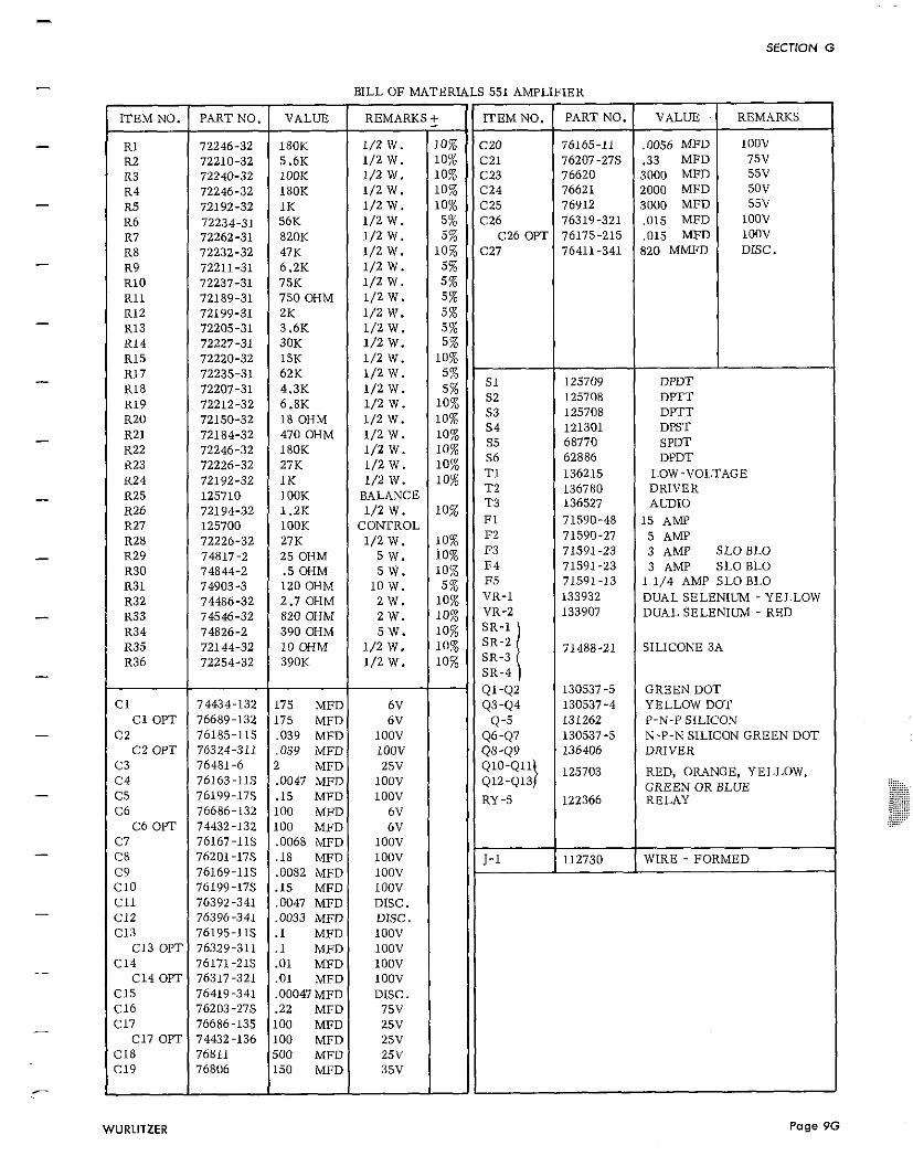
BILL OF MATERIALS 551 AMPLIFIER
76396-341 ,0033 MFD DISC. 1 6:: / 76195-11s 1 .I M I ioov I I C13 OPT 76329-311 .1 MFD lOOV
76167-11s ,0068 MFD lOOV I fi I 76201-17s I .18 MFDI ; 1 1 1 1-1
I
C14 ( 76171:21S 1:;: 1 :;:; 1 I I C14 OPT 76317 321
REMARKS
lOOV 75V 55V 5OV 55V
IOOV lOOV DISC.
112730
C15 76419-341 ,00047 MFD DISC. 1 F;; I 76203-27s " 2 2 1 ;;; I I 76686-135 100
- R1 R2 R3 R4 R5 R6 R7 R8 R9 R10 R11 R12 R13 R14 R15
WIRE - FORMED
C17 OPT 74432-136 100 MFD 25V MFD I ::: 1 1 MFD 1 iz: I 1
ITEM NO.
C20 C21 C23 C24 C25 C26
C26 OPT C27
76169-11s ,0082 MFD
R17 R18 R19 R20 R21 R22 K23 R24 R25 R26 R27 R28 R Z ~ R30 R31 R32 R33 R34 R35 R36
C l C1 OPT
C 2 C2 OPT
C3 C4 C5 C6
C6 OPT
72246-32 72210-32 72240-32 72246-32 72192-32 72234-31 72262-31 72232-32 72211-31 72237-31 72189-31 72199-31 72205-31 72227-31 72220-32
s1 s2 s3 s4 s5 s6 T1 T2 T 3 F1 F2
E34 F5 VR-l VR-2
I SR-4
Ql -Q2 93-Q4
Q-5 Q6-Q7 Qs-Q9 Q1O-Q1l} 412-413
RY -5
PART NO.
76165-11 76207-27s 76620 76621 76912 76319-321 76175-215 76411-341
VALUE
,0056 MFD .33 MFD 3000 MFD 2000 MFD 3000 MFD ,015 MFD ,015 MFD 820 MMFD
72235-31 72207-31 72212-32 72150-32 72184-32 72246-32 72226-32 72192-32 125710 72194-32 125700 72226-32 74817-2 74844-2 74903-3 74486-32 74546-32 74826-2 7 2 1 4 4 - 72254-32
74434.132 76689-132 76185-115 76324-311 76481-6 76163-11s 76199-17s 76686.132 74432-132
P
180K 5.6K IOOK 180K 1K 56K 820K 47K 6.2K 75K 750 OHM ZK 3.6K 30K 15K
125709 125708 125708 121301 68770 62886 136215 136780 136527 71590-48 71590-27 71591-23 71591-23 71591-13 133932 133907
71488-21
130537-5 130537-4 131262 130537-5 136406
125703
122366
DPDT DPTT DPTT DPST SPDT DPDT
LOW-VOLTAGE DRIVER AUDIO
15 AMP 5 AMP 3 AMP SLO BLO 3 AMP SLO BLO
1 1/4 AMP SLO BLO DUAL SELENIUM - YELLOW DUAL SELENIUM - RED
SILICONE 3A
GREEN DOT YELLOW DOT P-N-P SILICON N-P-N SILICON GREEN DOT DRIVER
RED, ORANGE, YELLOW, GREEN OR BLUE RELAY
62K 4.3K 6.8K 18 OHM 470 OHM 180K 27K 1 K lOOK 1.2K lOOK 27K 2 s OHM .5 OHM 120 OHM 2.7 OHM 820 OHM 390 OHM 1 0 OHM 390K
175 MFD 175 MFD ,039 MFD ,039 MFD 2 MFD ,0047 MFD . I 5 MFD 100 MFD 100 MFD
1 /2W. 1/2 W. l / 2 W . 1/2 W. 1/2 W. 1/2 W. 1/2 W. 1/2 W. 1 / 2 W . 1 / 2 W . 1/2 W . 1/2 W. 1/2 W . 1/2 W. 1/2 W.
10% 10% 10% 10% 10%
5% 5%
10% 5% 5 % 5% 5 % 5% 5%
10% 1/2 W. 1/2 W. 1/2 W. 1/2 W. 1/2 W . 1/2 W . 1/2 W. 1/2 W.
BALANCE 1/2 w.
CONTROL 1/2 W.
5 w. S W .
l o w . 2 W. 2 W. S W .
1/2 W. 1/2 W.
6V 6V
lOOV 100V 25V
lOOV lOOV
6V 6V
5% 5%
10% 10% 10% 1 % 10% 1 %
10%
10% io% 10% 5 %
10% 10% 10%
i::
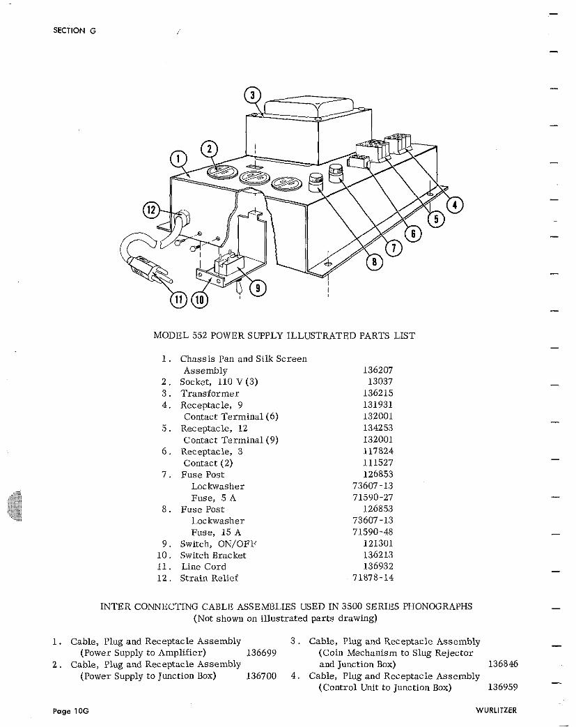
SECTION G
MODEL 552 POWER SUPPLY ILLUSTRATED PARTS LIST
1. Chassis Pan and Silk Screen Assembly
2 . Socket, 110 V (3) 3 . Transformer 4 . Receptacle, 9
Contact Terminal (6) 5 . Receptacle, 12
Contact Terminal (9) 6 . Receptacle, 3
Contact (2) 7 . Fuse Post
Loc kwasher Fuse, 5 A
8 . Fuse Post Loc kwasher Fuse, 15 A
9 . Switch, ON/OFF 1 0 . Switch Bracket 11. Line Cord 1 2 . Strain Relief
INTER CONNECTING CABLE ASSEMBLIES USED IN 3500 SERIES PHONOGRAPHS (Not shown on illustrated par ts drawing)
1. Cable, Plug and Receptacle Assembly 3 . Cable, Plug and Receptacle Assembly - (Power Supply to Amplifier) 136699 (Coin Mechanism to Slug Rejector
2 . Cable, Plug and Receptacle Assembly and Junction Box) 136846 (Power Supply to Junction Box) 136700 4 . Cable, Plug and Receptacle Assembly
136959 -
(Control Unit to Junction Box)
Page 10G WURLITZER
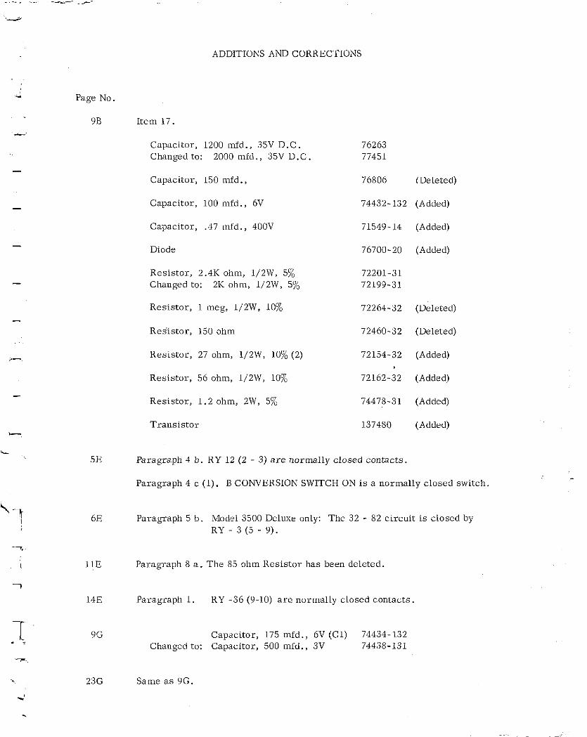
Page No.
98
ADDITIONS AND CORRECTIONS
Item 17.
Capacitor, 1200 mfd., 35V D.C. Changed to: 2000 mid., 35V D.C
Capacitor, 150 mfd.,
Capacitor, 100 mid., 6V
Capacitor, .47 mld., 400V
Diode
Resistor , 2.4K ohm, 1/2W, 5% Changed to: 2K ohm, 1/2W, 5%
Resistor , 1 meg, 1/2W, 10%
Res'istor, 150 ohm
Resistor , 27 ohm, 1/2W, 10% (2)
Resistor , 56 ohm, 1/2W, 10%
Resistor , 1 .2 ohm, 2W, 5%
Trans is tor
76806 (Deleted)
74432-132 (Added)
71549-14 (Added)
76700-20 (Added)
72264-32 (Deleted)
72460-32 (Deleted)
72154-32 (Added)
72162-32 (Added)
74478-31 (Added)
137480 (Added)
Paragraph 4 b. RY 12 (2 - 3) a r e normally closed contacts.
Paragraph 4 c (1). B CONVERSION SWITCH ON is a normally closed switch.
Paragraph 5 b . Model 3500 Deluxe only: The 32 - 82 circui t i s closed by RY - 3 (5 - 9).
Paragraph 8 a. The 85 ohm Resistor has been deleted.
Paragraph 1. RY -36 (9-10) a r e normally closed contacts.
Capacitor, 175 mfd., 6V (Cl) 74434-132 Changed to: Capacitor, 500 mfd., 3V 74438-131
Same a s 9G.
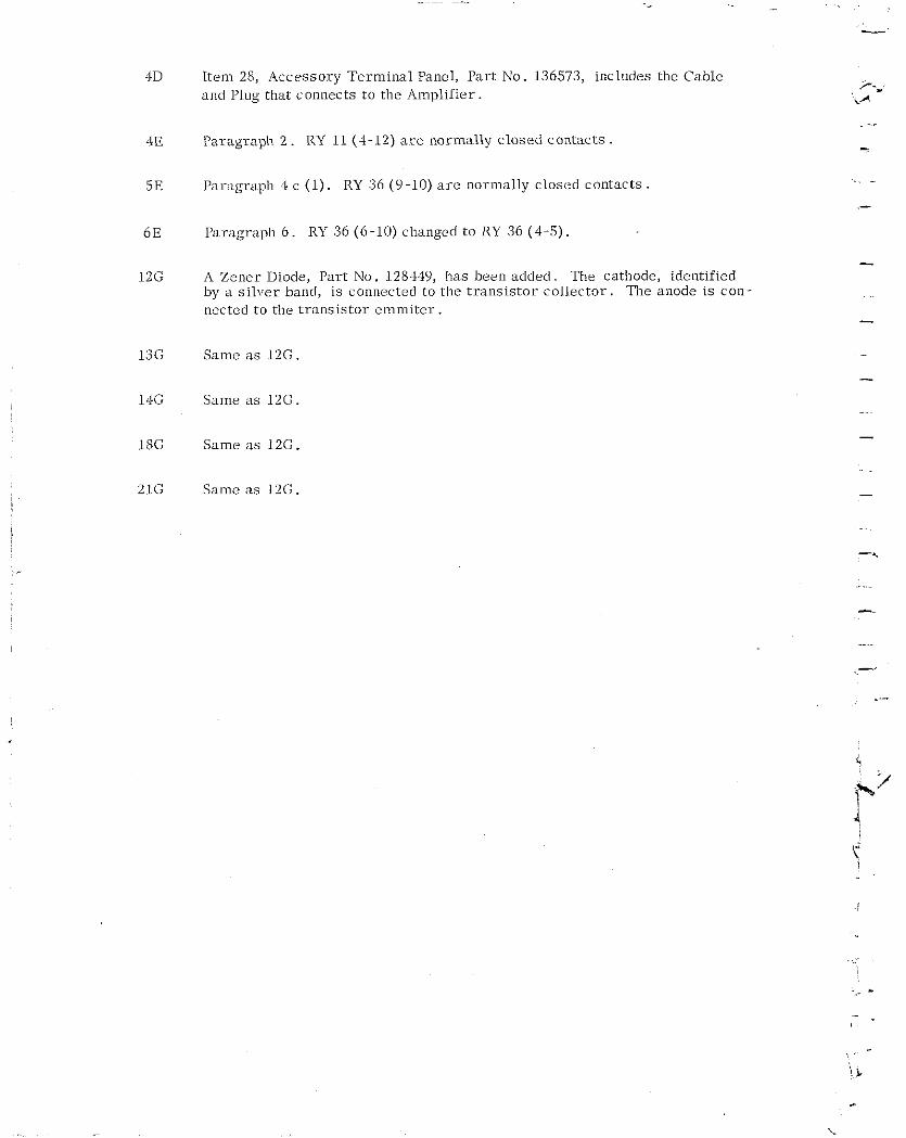
Item 28, Accessory Te rmina l Panel, Par t No. 136573, includes the Cable and Plug that connects t o the Amplif ier .
Paragrap11 2 . RY 11 (4-12) a r e norlnally c losed contacts
Par ,~gr ,~ph 4 c (1) . RY 36 (9-10) a r e n o r n ~ a l l y closed contacts
Paragraph 6 . RY 36 (6-10) changed t o RY 36 (4-5) .
A Zener Diode, Par t No. 128449, has been added . The cathode, identified by a s i l ve r band, i s connected to the t r an s i s t o r co l l e c to r . The anode i s con- ncctcd t o the t r an s i s t o r emln i t e r .
Samc a s 12G.
Same 3s 12G.
Same a s 12G.
Same a s 12G.
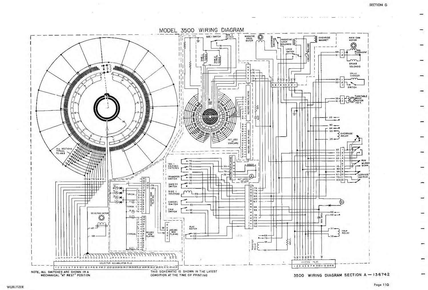
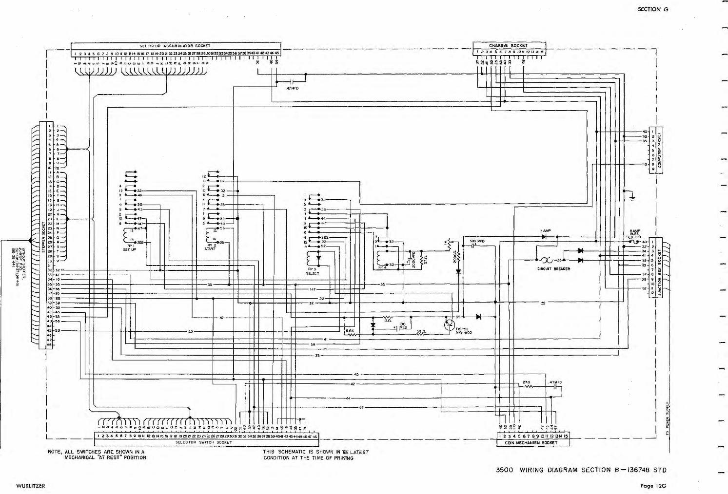
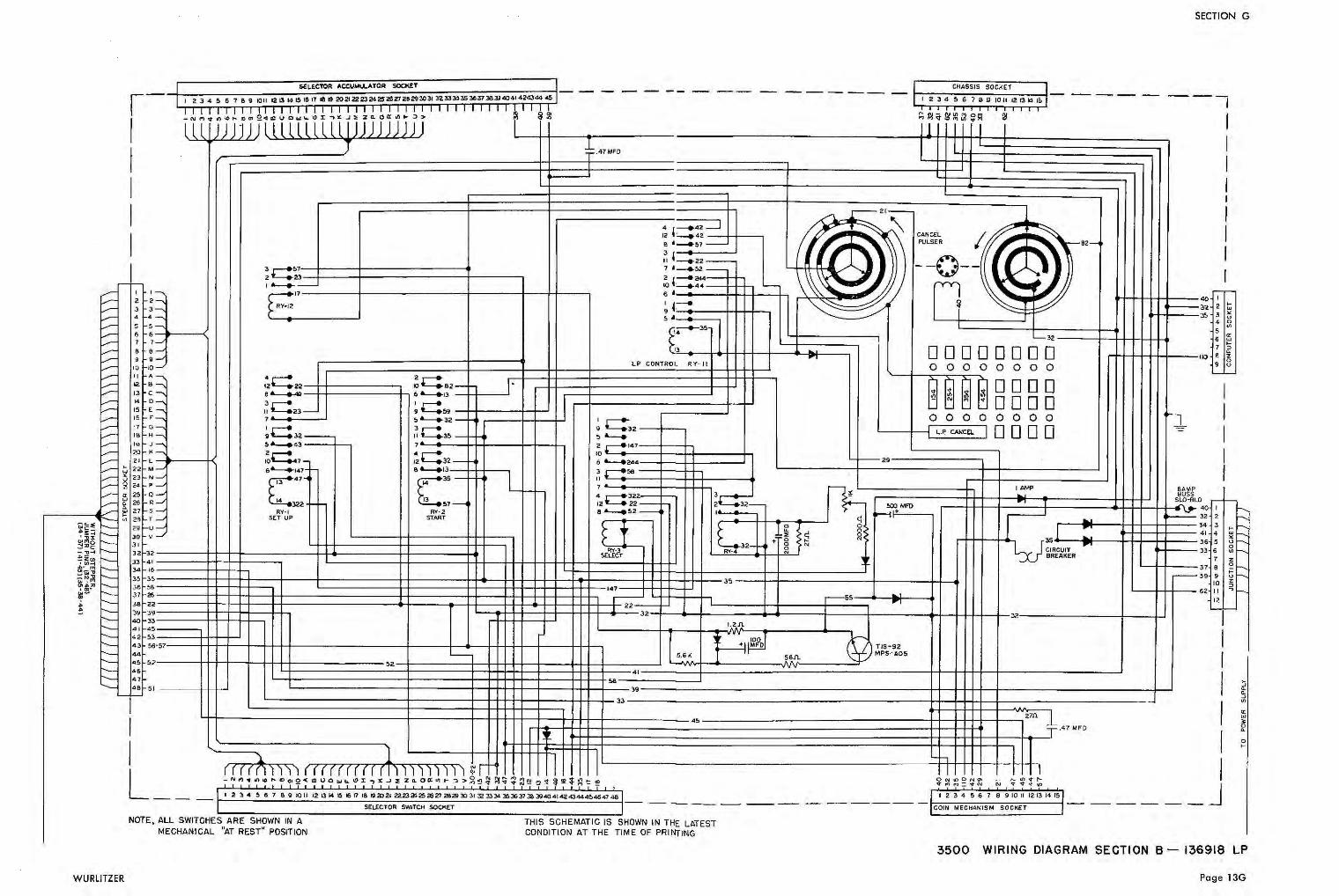
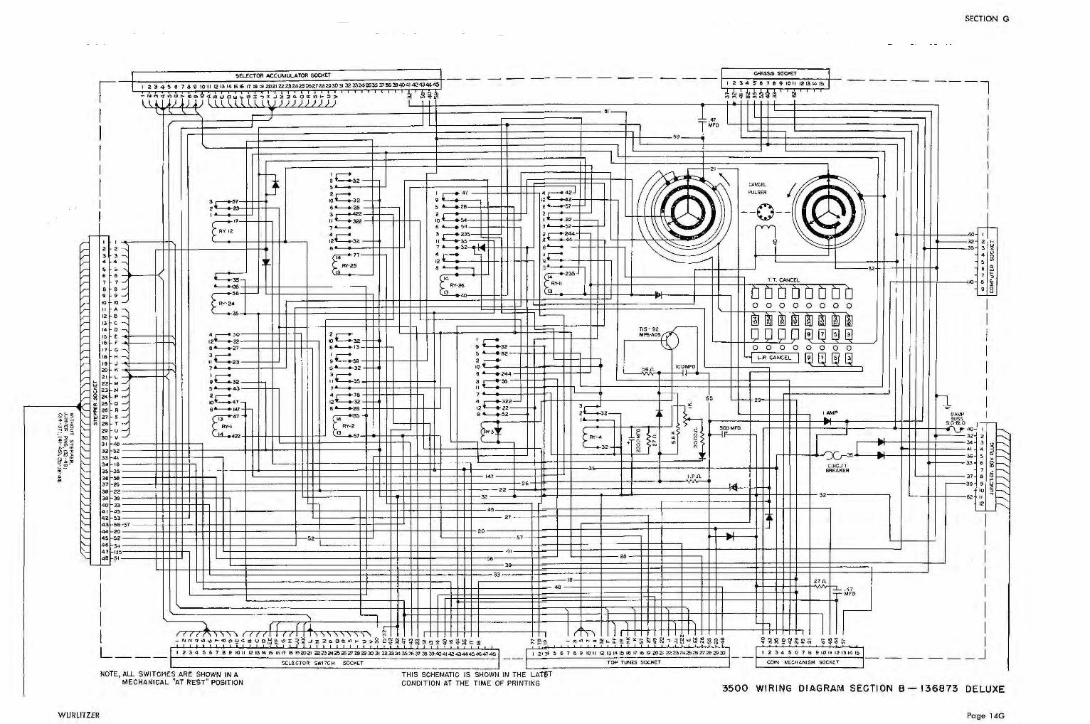
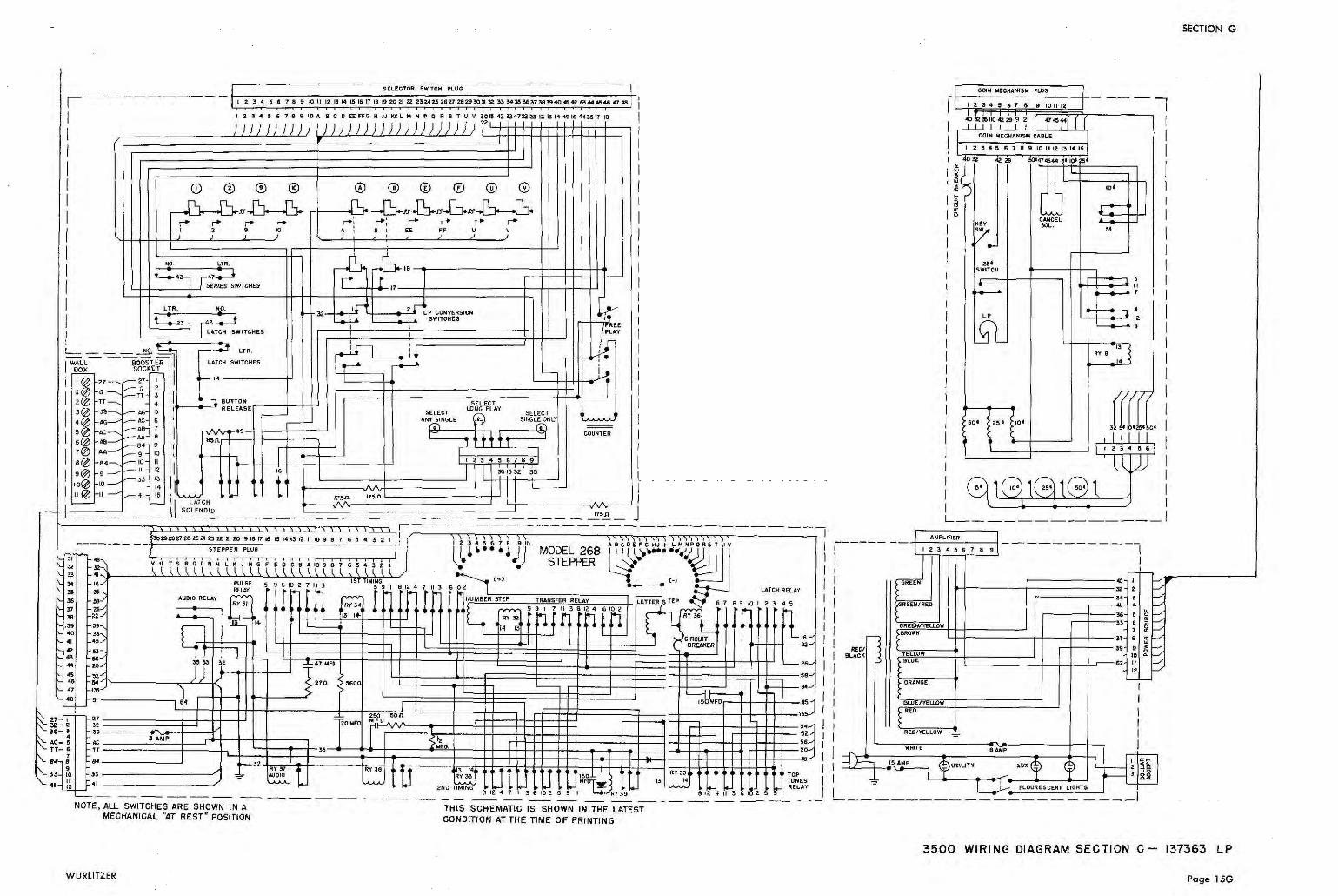
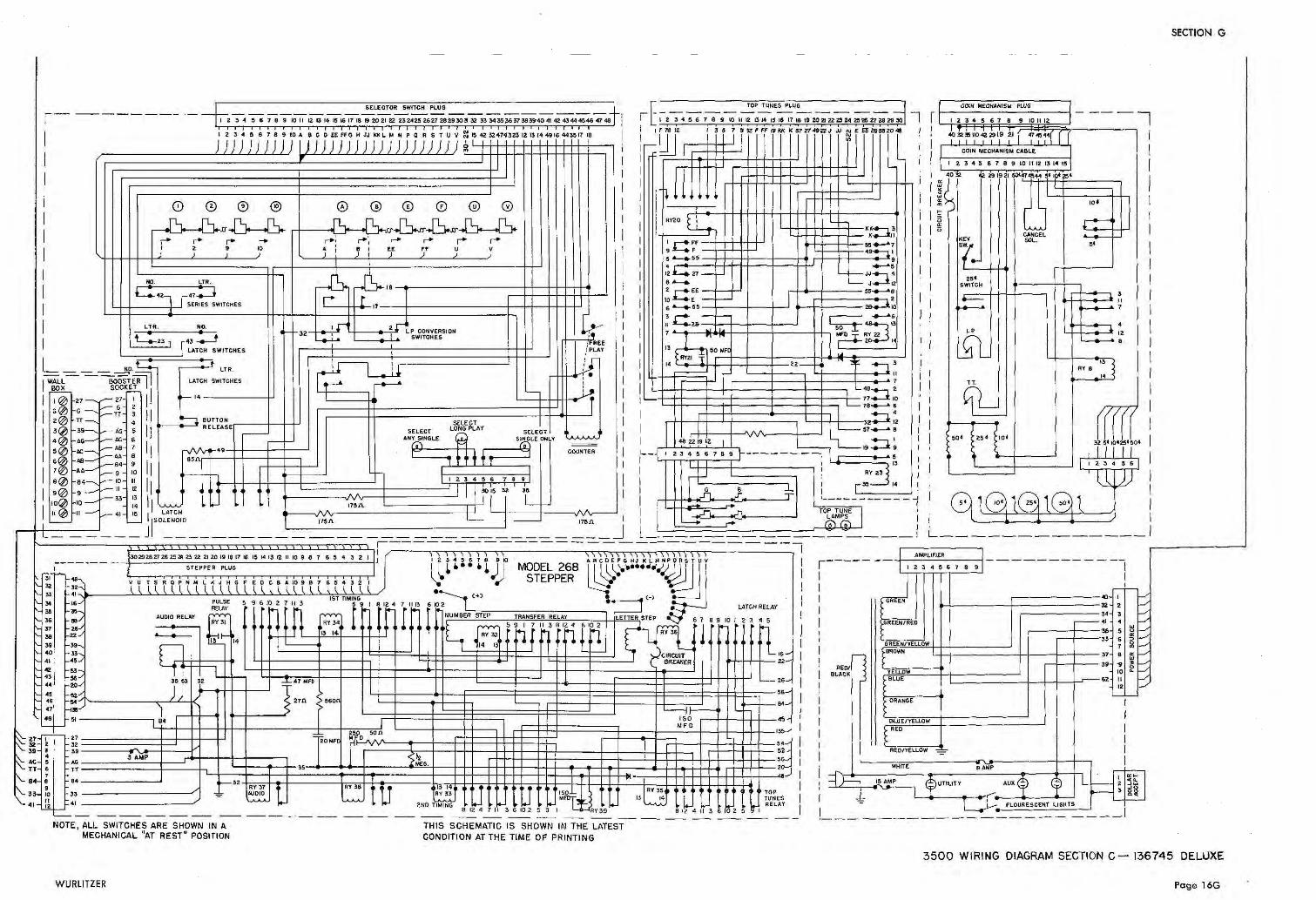
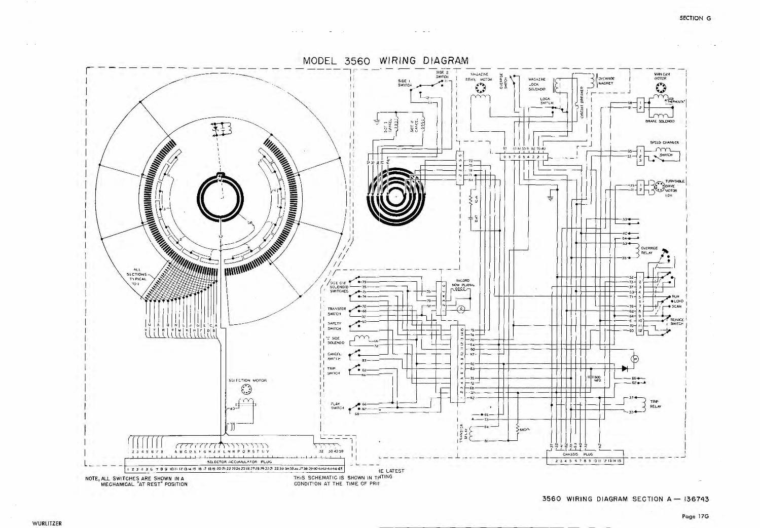
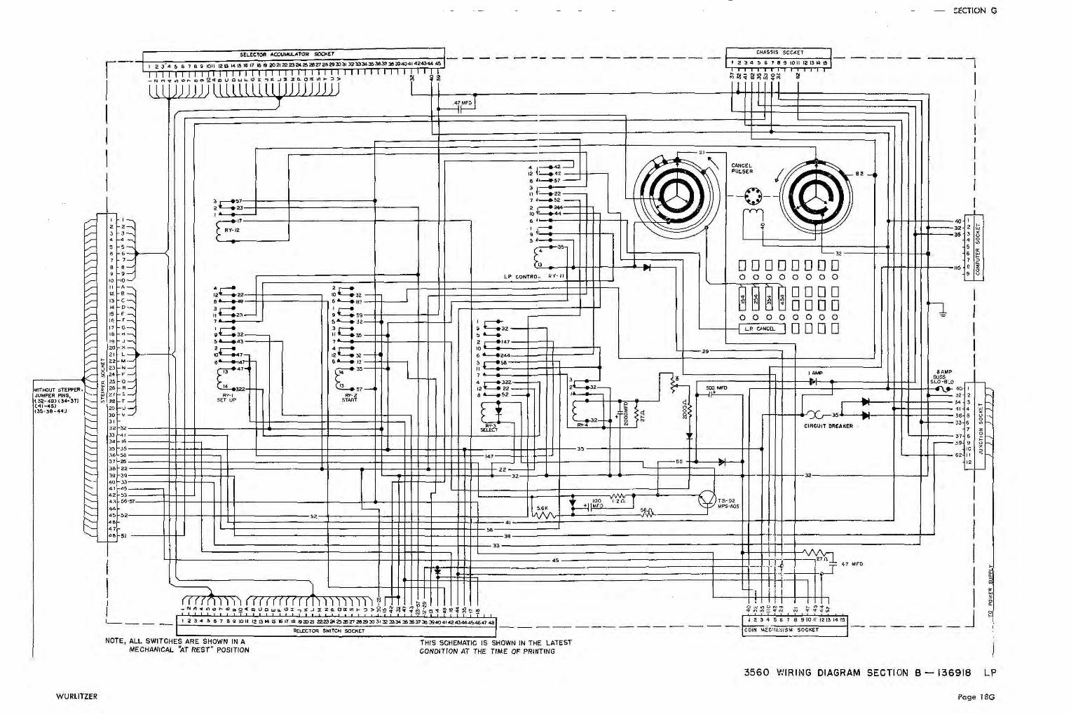
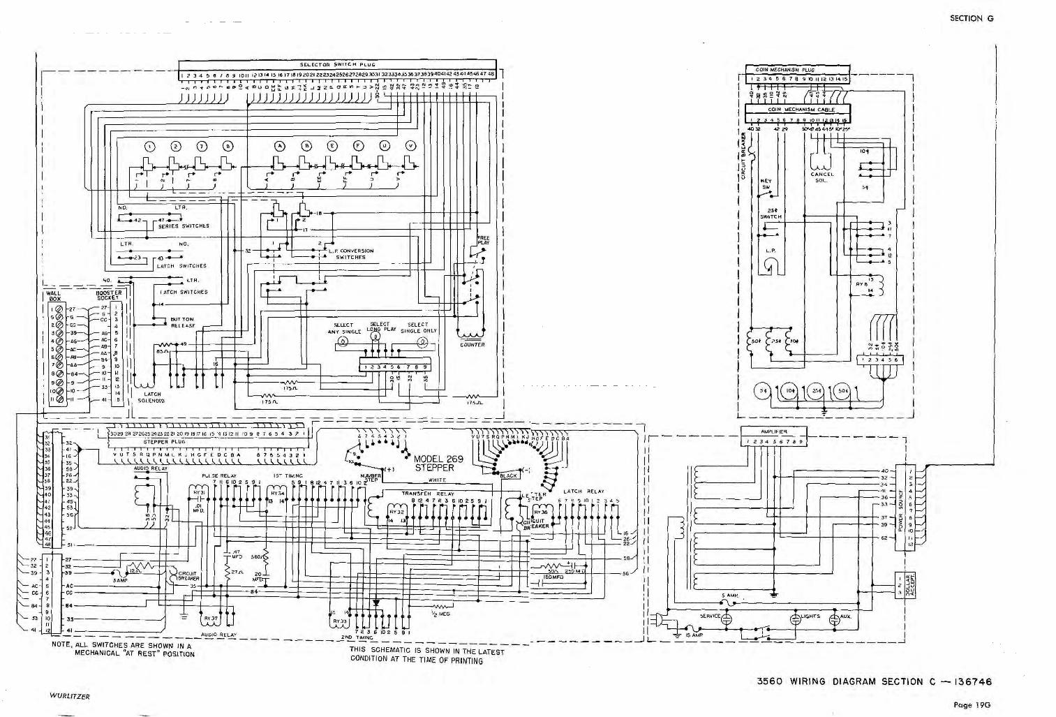
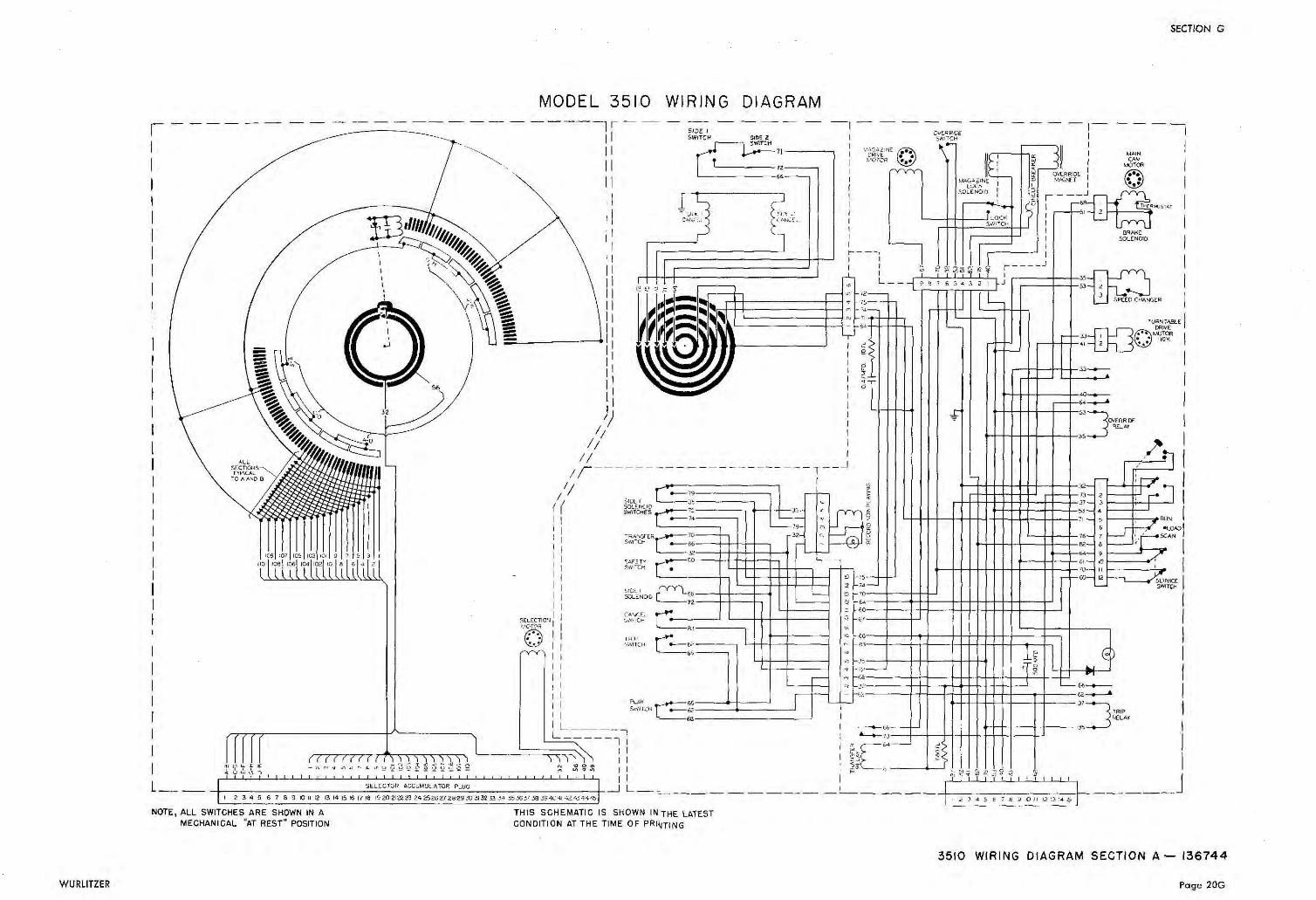
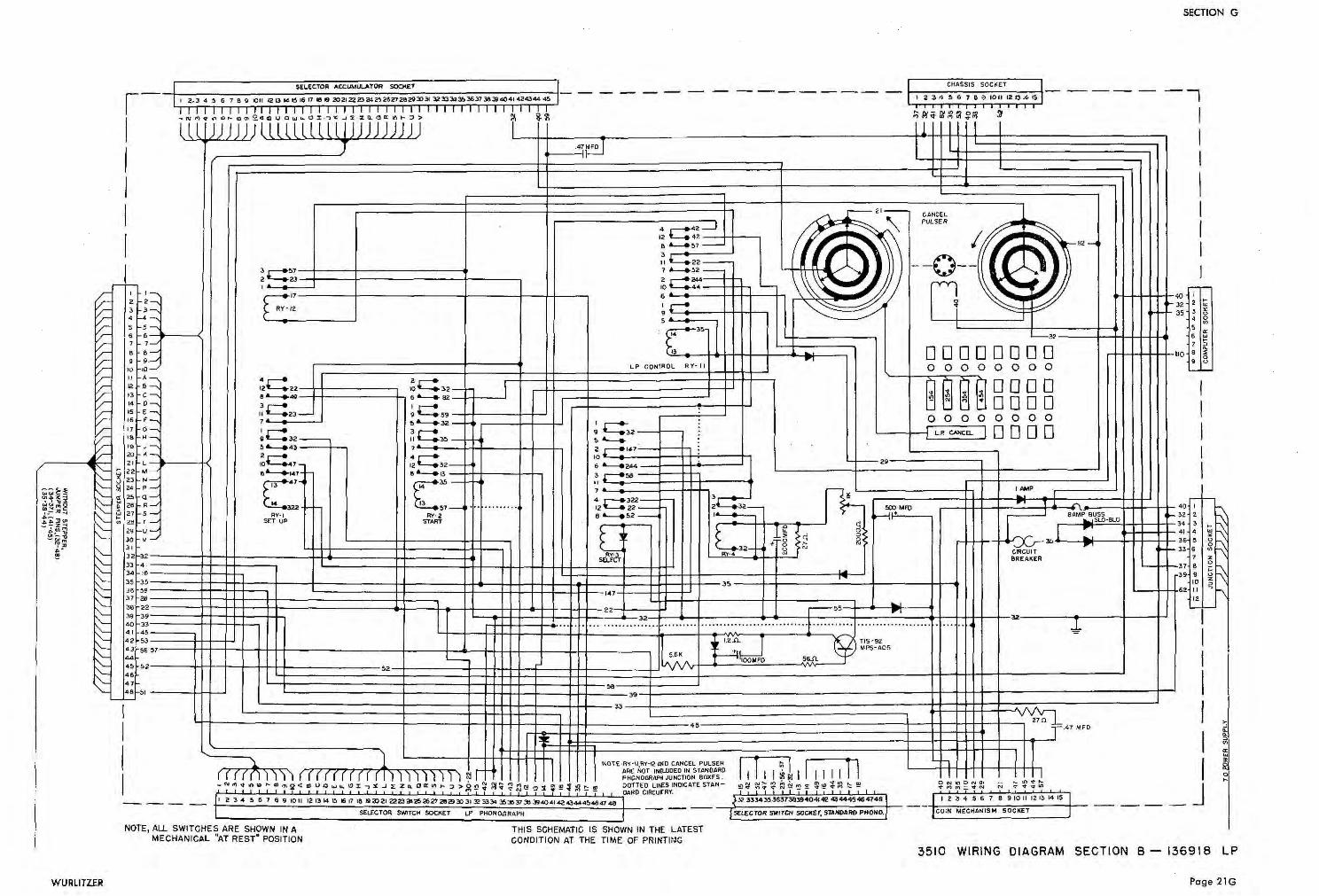
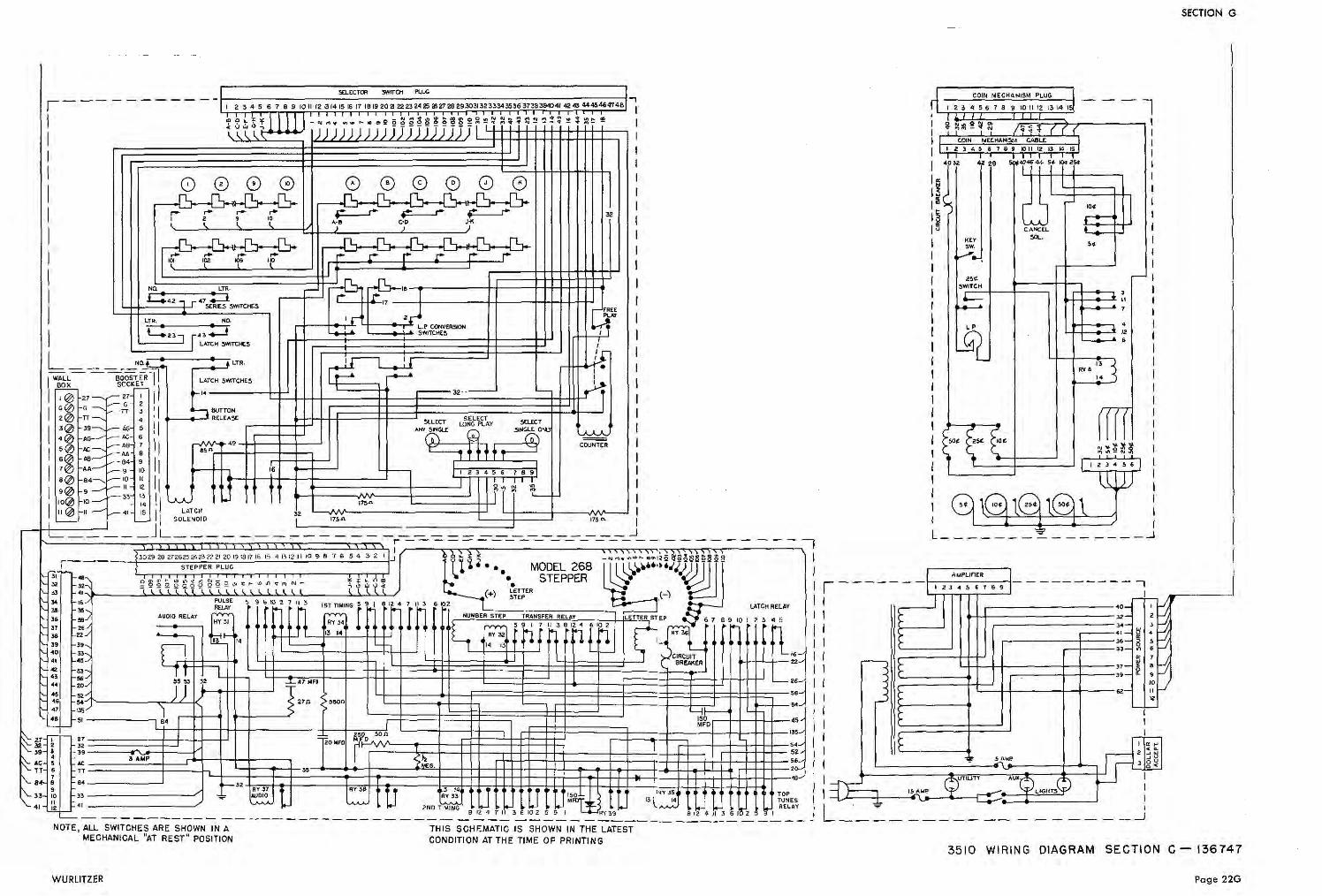
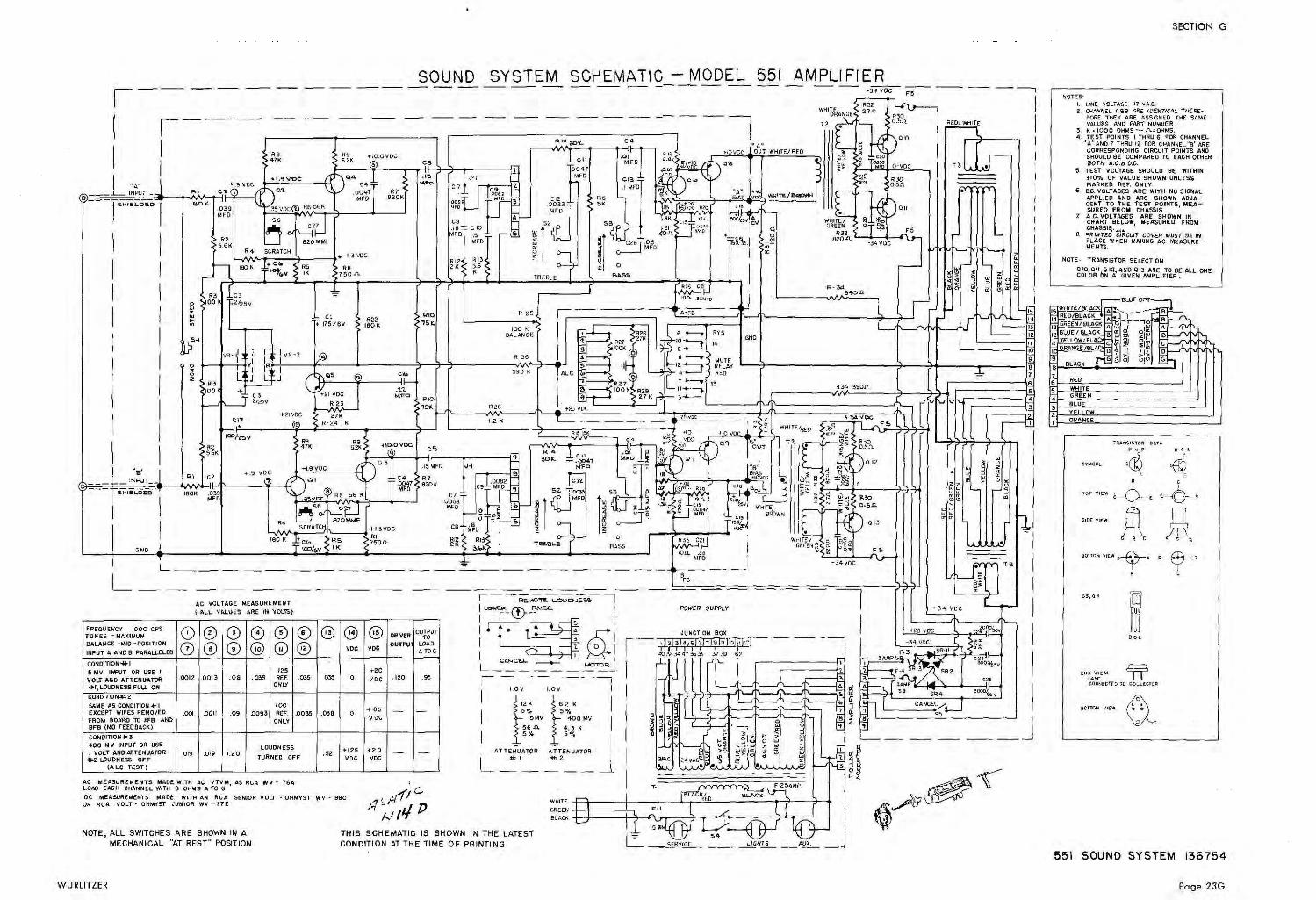


![BLADES [PPT]](https://img.pdfslide.us/doc/110x75/55cf9bc6550346d033a75508/blades-ppt.jpg)