Embed Size (px)
Citation preview

Ta
ble
of C
on
ten
ts
Table of Contents 1. INTRODUCTION ............................................................................ 1
Features .......................................................................................... 2 What it comes with ......................................................................... 3
2. OPERATION BASICS ................................................................... 4
Mounting ......................................................................................... 4 Powering up .................................................................................... 7 Display and Keypad ........................................................................ 8 Menus ........................................................................................... 10 Modes ........................................................................................... 10 Tools ............................................................................................. 13
3. ACCIDENT RECONSTRUCTION USE ....................................... 14
Initial Setup ................................................................................... 14 Get VC4000 Ready ...................................................................... 15 Measuring Drag Factor ................................................................. 18 Testing Brake Performance .......................................................... 19 Measuring Coefficient of Friction .................................................. 20 Light Impact Testing ..................................................................... 23 Avoiding False Triggering ............................................................. 25 Measuring Slope ........................................................................... 26 Acceleration Testing ..................................................................... 27 Accel/Brake Run ........................................................................... 29
4. TRANSIT USE ............................................................................. 31
Initial Setup ................................................................................... 31 Get VC4000 Ready ...................................................................... 32 Testing Brake Performance .......................................................... 35
5. ENGINEERING USE .................................................................... 37
Initial Setup ................................................................................... 37 Get VC4000 Ready ...................................................................... 37 Testing Brake Performance .......................................................... 40 Acceleration Testing ..................................................................... 42 Monitor Data ................................................................................. 45
6. TOOLS ......................................................................................... 46
Monitor Data ................................................................................. 47 Crash Mode .................................................................................. 51 Calibration Check ......................................................................... 52 Deleted Run .................................................................................. 55 SD Card Options .......................................................................... 56 Accel/Brake Runs ......................................................................... 58 Enter Suffix ................................................................................... 59

Measuring Slope ........................................................................... 60 7. VC4000 SETUP ........................................................................... 61
Setup Flowchart ............................................................................ 63 G Threshold .................................................................................. 65 Vehicle ID ..................................................................................... 65 Set Defaults .................................................................................. 66 Date/Time ..................................................................................... 67 Pitch/Roll Factors ......................................................................... 67 User Type ..................................................................................... 69 English/Metric ............................................................................... 71 RS232 Port ................................................................................... 72 Brake MPH ................................................................................... 72 Sensors Setup .............................................................................. 73
OBDII Sensors .......................................................................... 73 Analog Out ................................................................................ 74 GPS Sensors ............................................................................ 75
Accelerometer Setup .................................................................... 76 G Summation ............................................................................ 76 G Smoothing ............................................................................. 78 Zeroing On/Off .......................................................................... 79 Accelerometer Range ............................................................... 79 G Adjust .................................................................................... 79 Graph Range ............................................................................ 80 Alarm Threshold ........................................................................ 80
Performance Setup ....................................................................... 81 Vehicle Weight .......................................................................... 81 Countdown On/Off .................................................................... 82
Maintenance ................................................................................. 82 Unit Information ......................................................................... 82 Run Tests .................................................................................. 82 Discharge Battery ..................................................................... 82
8. SENSOR INPUT .......................................................................... 83
OBDII Input ................................................................................... 84 Analog Output ............................................................................... 84 GPS Input ..................................................................................... 85 External Activation ........................................................................ 86
9. REVIEW - PRINT DATA .............................................................. 90
Display a Run ............................................................................... 90 Print Runs ..................................................................................... 91 Store to SD Flash drive ................................................................ 91
10. PC INTERFACE ......................................................................... 92
RS232 Ports ................................................................................. 93
Ta
ble
of C
on
ten
ts
USB Port ....................................................................................... 95
11. UPDATING FIRMWARE ............................................................ 96 12. CHARGING THE BATTERY ..................................................... 98 13. CUSTOMER SERVICE .............................................................. 99
Warranty ....................................................................................... 99 Repairs ......................................................................................... 99 Options, Upgrades and Accessories .......................................... 100
14. TROUBLESHOOTING ............................................................. 101 15. SPECIFICATIONS ................................................................... 103
VC4000 Manual 1
VERICOM VC4000PC AND BRAKE METER OWNERS MANUAL
Revision 1.8, October 2, 2013
1. INTRODUCTION
ecades of refinement make the VC4000 the best yet. The VC4000 has been designed for ease of use and simplicity of operation for quick and easy results, yet has advanced features for doing much more. The unit is preprogrammed
with standard defaults so that it is ready to operate immediately. The new VC4000 measures X, Y and Z axis acceleration, OBDII and GPS. The more acquainted you become with the VC4000 the more applications you will discover.
D
VC4000 Manual 2
Intro
du
ctio
n
3-axis accelerometer
Single vacuum cup mounting
Summation of X+Y+Z vectors
Analog output of sensors or speed
Menu selection software
RS232 port
USB port
Updateable firmware via USB interface
Delete individual Runs
Battery shows charging on display and LED on front
Audible G alarm
Calculates adjusted braking distance
115 minutes of internal data storage
2GB SD flash memory card for extra storage (PC)
GPS speed and position (with GPS module) (PC)
OBDII input compatible (PC)
Selectable G range of 2 or 6 G (PC)
Profile Professional included (PC)
Can send data directly to Profile (Data Streaming) (PC)
Variable sample rate of 1, 10, 100, 500 or 1000Hz (PC) This manual covers everything necessary to operate your VC4000. For further information and details, see our web site www.vericomcomputers.com and go to the support page. There will be documents with tips on various subjects. Look to the support pages for firmware updates for your VC4000. How to use this manual The gray area on the page edges allow you to quickly thumb through to find the section you want. Use the Table of Contents at the beginning to quickly search for the general section you are interested in. If you can’t find what you are looking for, go to our web site’s support pages for more detailed information. This manual covers the VC4000 Brake Meter and the VC4000PC. When you see “(PC)” means it applies to the VC4000PC model only.
VC4000 Features
VC4000 Manual 3
Check to see that the following items are supplied with your VC4000:
1 VC4000 with single cup mounting assembly 1 Power cord (to cigarette lighter) 1 AC wall adapter 1 USB interface cable (PC) 1 VC4000 manual 1 Profile CD (PC) 1 Carrying case
Optional Accessories:
RS232/Analog out splitter
GPS input (PC)
OBDII input (PC)
Activation switches
Reaction time switches
Portable thermal micro printer
Variety of mounting bases
Two cup mounting system
Extra carrying case
Wireless modems for up to 7 mile data transfer (PC)
What it comes with
Op
era
tion
s B
as
ics
VC4000 Manual 4
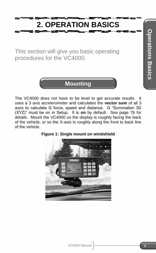
2. OPERATION BASICS
This section will give you basic operating procedures for the VC4000.
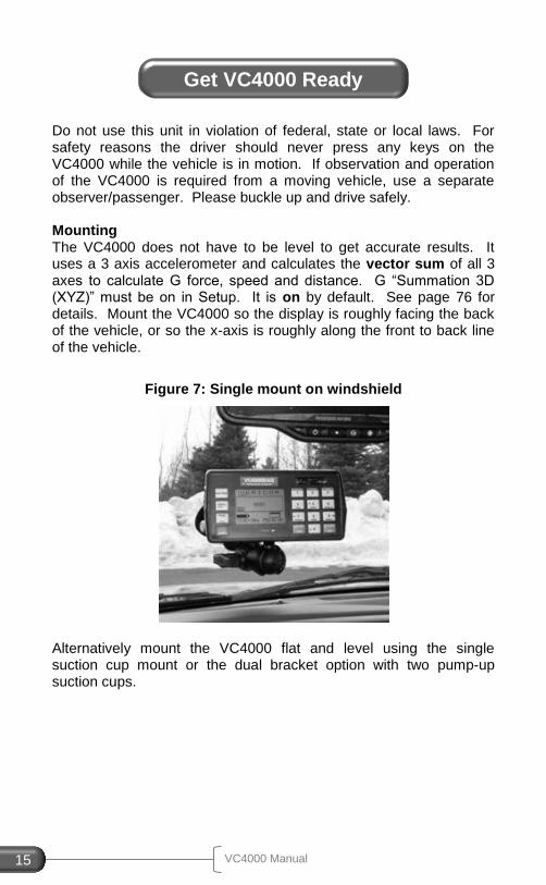
The VC4000 does not have to be level to get accurate results. It uses a 3 axis accelerometer and calculates the vector sum of all 3 axes to calculate G force, speed and distance. G “Summation 3D (XYZ)” must be on in Setup. It is on by default. See page 76 for details. Mount the VC4000 so the display is roughly facing the back of the vehicle, or so the X-axis is roughly along the front to back line of the vehicle.
Figure 1: Single mount on windshield
Mounting
VC4000 Manual 5
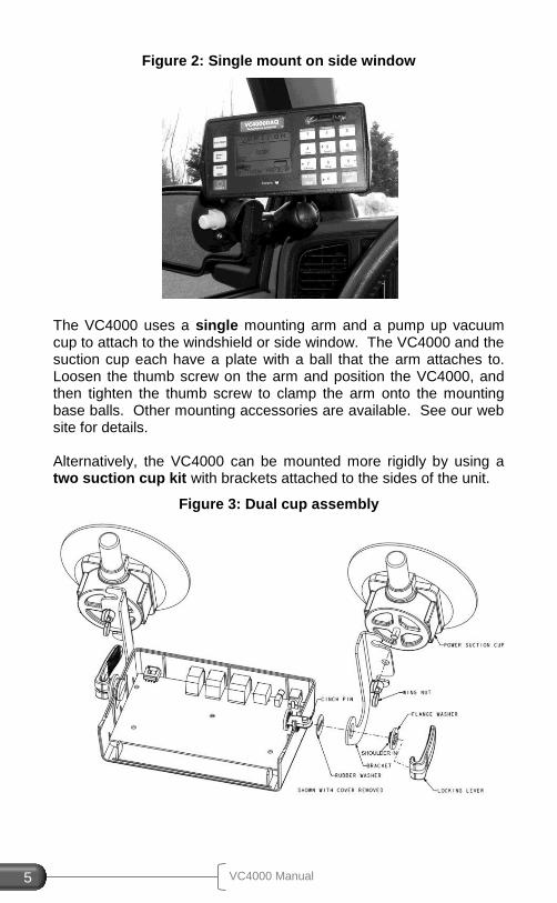
Figure 2: Single mount on side window
The VC4000 uses a single mounting arm and a pump up vacuum cup to attach to the windshield or side window. The VC4000 and the suction cup each have a plate with a ball that the arm attaches to. Loosen the thumb screw on the arm and position the VC4000, and then tighten the thumb screw to clamp the arm onto the mounting base balls. Other mounting accessories are available. See our web site for details. Alternatively, the VC4000 can be mounted more rigidly by using a two suction cup kit with brackets attached to the sides of the unit.
Figure 3: Dual cup assembly
Op
era
tion
s B
as
ics
VC4000 Manual 6
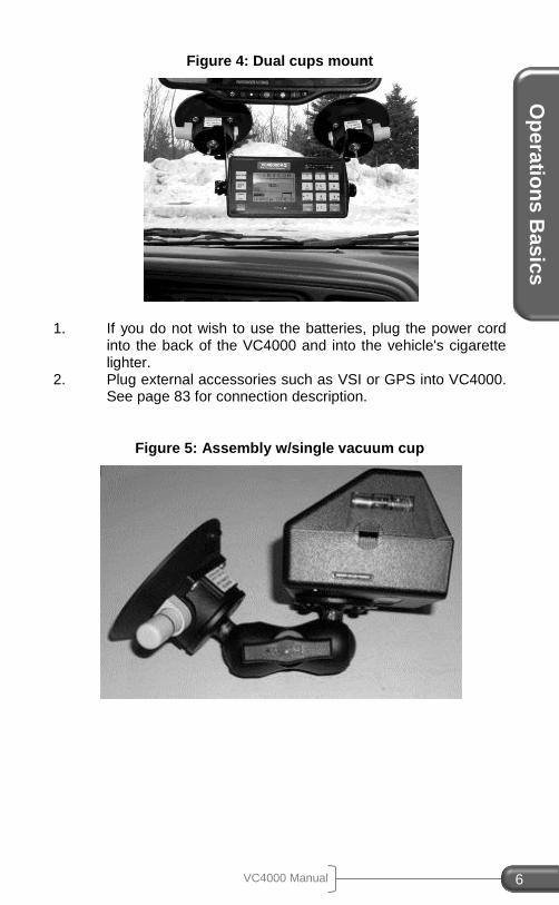
Figure 4: Dual cups mount
1. If you do not wish to use the batteries, plug the power cord
into the back of the VC4000 and into the vehicle's cigarette lighter.
2. Plug external accessories such as VSI or GPS into VC4000. See page 83 for connection description.
Figure 5: Assembly w/single vacuum cup
VC4000 Manual 7
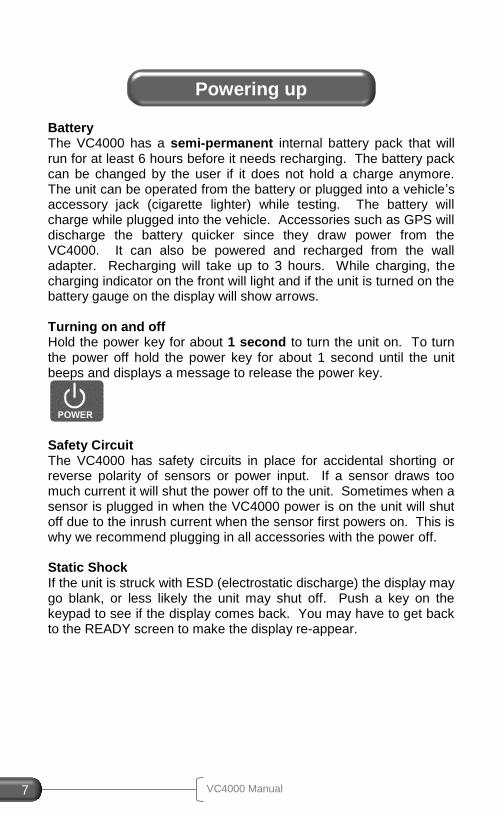
Battery The VC4000 has a semi-permanent internal battery pack that will run for at least 6 hours before it needs recharging. The battery pack can be changed by the user if it does not hold a charge anymore. The unit can be operated from the battery or plugged into a vehicle’s accessory jack (cigarette lighter) while testing. The battery will charge while plugged into the vehicle. Accessories such as GPS will discharge the battery quicker since they draw power from the VC4000. It can also be powered and recharged from the wall adapter. Recharging will take up to 3 hours. While charging, the charging indicator on the front will light and if the unit is turned on the battery gauge on the display will show arrows. Turning on and off Hold the power key for about 1 second to turn the unit on. To turn the power off hold the power key for about 1 second until the unit beeps and displays a message to release the power key.
Safety Circuit The VC4000 has safety circuits in place for accidental shorting or reverse polarity of sensors or power input. If a sensor draws too much current it will shut the power off to the unit. Sometimes when a sensor is plugged in when the VC4000 power is on the unit will shut off due to the inrush current when the sensor first powers on. This is why we recommend plugging in all accessories with the power off. Static Shock If the unit is struck with ESD (electrostatic discharge) the display may go blank, or less likely the unit may shut off. Push a key on the keypad to see if the display comes back. You may have to get back to the READY screen to make the display re-appear.
Powering up
Op
era
tion
s B
as
ics
VC4000 Manual 8
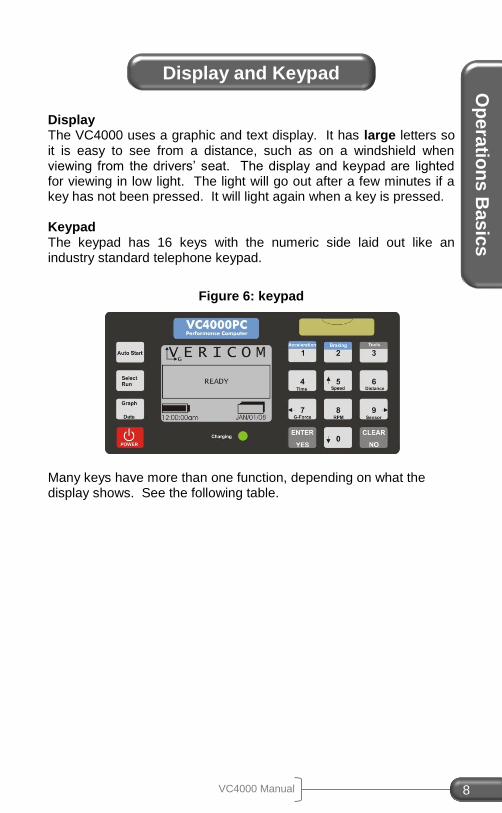
Display The VC4000 uses a graphic and text display. It has large letters so it is easy to see from a distance, such as on a windshield when viewing from the drivers’ seat. The display and keypad are lighted for viewing in low light. The light will go out after a few minutes if a key has not been pressed. It will light again when a key is pressed. Keypad The keypad has 16 keys with the numeric side laid out like an industry standard telephone keypad.
Figure 6: keypad
Many keys have more than one function, depending on what the display shows. See the following table.
Display and Keypad
VC4000 Manual 9
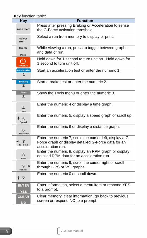
Key function table:
Key Function
Auto Start
Press after pressing Braking or Acceleration to sense the G-Force activation threshold.
Select
Run
Select a run from memory to display or print.
Graph
Data
While viewing a run, press to toggle between graphs and data of run.
POWER
Hold down for 1 second to turn unit on. Hold down for 1 second to turn unit off.
1Acceleration
Start an acceleration test or enter the numeric 1.
2Braking
Start a brake test or enter the numeric 2.
3
Tools
Show the Tools menu or enter the numeric 3.
Time
4
Enter the numeric 4 or display a time graph.
Speed
5
Enter the numeric 5, display a speed graph or scroll up.
Distance
6
Enter the numeric 6 or display a distance graph.
G-Force
7
Enter the numeric 7, scroll the cursor left, display a G-Force graph or display detailed G-Force data for an acceleration run.
RPM
8
Enter the numeric 8, display an RPM graph or display detailed RPM data for an acceleration run.
Sensor
9
Enter the numeric 9, scroll the cursor right or scroll through GPS or VSI graphs.
0
Enter the numeric 0 or scroll down.
ENTER
YES
Enter information, select a menu item or respond YES to a prompt.
CLEAR
NO
Clear memory, clear information, go back to previous screen or respond NO to a prompt.
Op
era
tion
s B
as
ics
VC4000 Manual 10
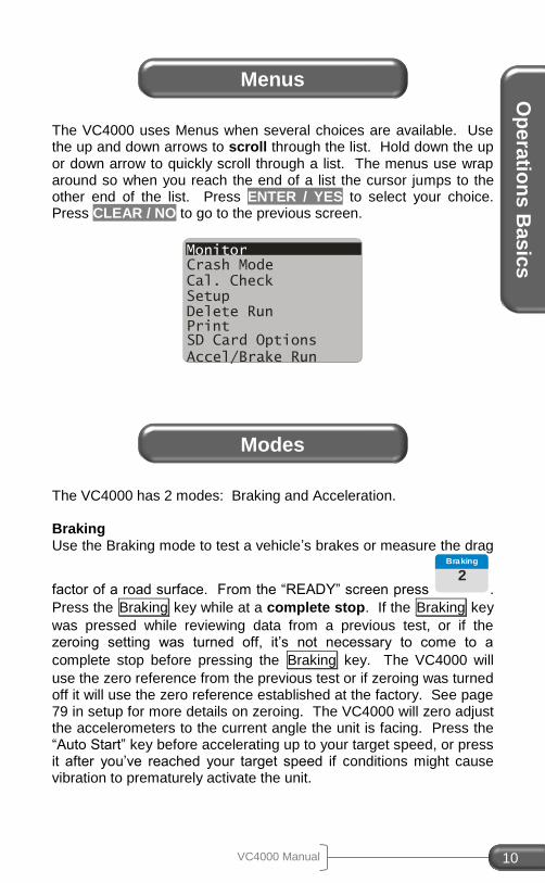
The VC4000 uses Menus when several choices are available. Use the up and down arrows to scroll through the list. Hold down the up or down arrow to quickly scroll through a list. The menus use wrap around so when you reach the end of a list the cursor jumps to the other end of the list. Press ENTER / YES to select your choice. Press CLEAR / NO to go to the previous screen.
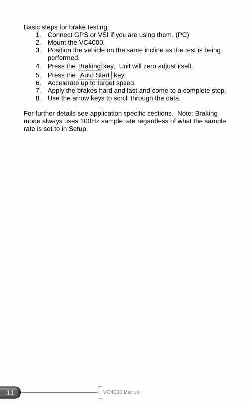
The VC4000 has 2 modes: Braking and Acceleration. Braking Use the Braking mode to test a vehicle’s brakes or measure the drag
factor of a road surface. From the “READY” screen press 2
Braking
.
Press the Braking key while at a complete stop. If the Braking key
was pressed while reviewing data from a previous test, or if the zeroing setting was turned off, it’s not necessary to come to a
complete stop before pressing the Braking key. The VC4000 will
use the zero reference from the previous test or if zeroing was turned off it will use the zero reference established at the factory. See page 79 in setup for more details on zeroing. The VC4000 will zero adjust the accelerometers to the current angle the unit is facing. Press the “Auto Start” key before accelerating up to your target speed, or press it after you’ve reached your target speed if conditions might cause vibration to prematurely activate the unit.
Menus
Monitor
Cal. Check Setup Delete Run Print SD Card Options
Accel/Brake Run
Crash Mode
Modes
VC4000 Manual 11
Basic steps for brake testing: 1. Connect GPS or VSI if you are using them. (PC) 2. Mount the VC4000. 3. Position the vehicle on the same incline as the test is being
performed.
4. Press the Braking key. Unit will zero adjust itself.
5. Press the Auto Start key.
6. Accelerate up to target speed. 7. Apply the brakes hard and fast and come to a complete stop. 8. Use the arrow keys to scroll through the data.
For further details see application specific sections. Note: Braking mode always uses 100Hz sample rate regardless of what the sample rate is set to in Setup.
Op
era
tion
s B
as
ics
VC4000 Manual 12
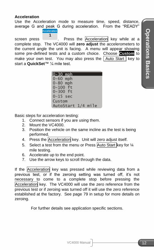
Acceleration Use the Acceleration mode to measure time, speed, distance, average G and peak G during acceleration. From the “READY”
screen press 1
Acceleration
. Press the Acceleration key while at a
complete stop. The VC4000 will zero adjust the accelerometers to the current angle the unit is facing. A menu will appear showing some pre-defined tests and a custom choice. Choose Custom to
make your own test. You may also press the Auto Start key to
start a QuickSet™ ¼ mile test.
Basic steps for acceleration testing:
1. Connect sensors if you are using them. 2. Mount the VC4000. 3. Position the vehicle on the same incline as the test is being
performed.
4. Press the Acceleration key. Unit will zero adjust itself.
5. Select a test from the menu or Press Auto Start key for ¼
mile testing. 6. Accelerate up to the end point. 7. Use the arrow keys to scroll through the data.
If the Acceleration key was pressed while reviewing data from a
previous test, or if the zeroing setting was turned off, it’s not necessary to come to a complete stop before pressing the
Acceleration key. The VC4000 will use the zero reference from the
previous test or if zeroing was turned off it will use the zero reference established at the factory. See page 79 in setup for more details on zeroing.
For further details see application specific sections.
0-30 mph 0-60 mph 0-80 mph 0-100 ft 0-300 ft
0-15 sec
Custom AutoStart 1/4 mile
VC4000 Manual 13
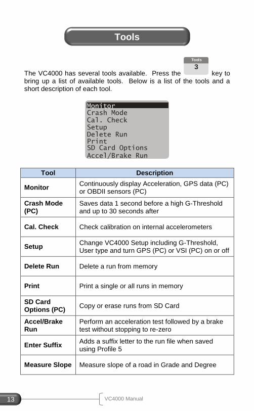
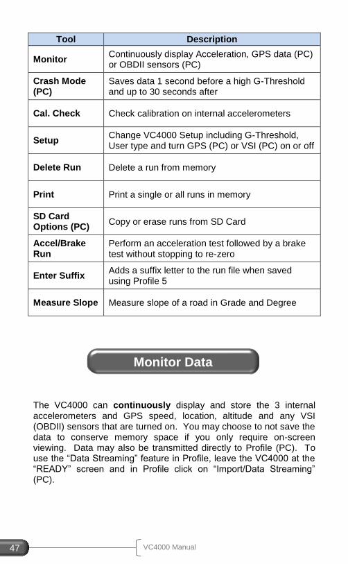
The VC4000 has several tools available. Press the 3
Tools
key to bring up a list of available tools. Below is a list of the tools and a short description of each tool.
Tool Description
Monitor Continuously display Acceleration, GPS data (PC) or OBDII sensors (PC)
Crash Mode (PC)
Saves data 1 second before a high G-Threshold and up to 30 seconds after
Cal. Check Check calibration on internal accelerometers
Setup Change VC4000 Setup including G-Threshold, User type and turn GPS (PC) or VSI (PC) on or off
Delete Run Delete a run from memory
Print Print a single or all runs in memory
SD Card Options (PC)
Copy or erase runs from SD Card
Accel/Brake Run
Perform an acceleration test followed by a brake test without stopping to re-zero
Enter Suffix Adds a suffix letter to the run file when saved using Profile 5
Measure Slope Measure slope of a road in Grade and Degree
Tools
Monitor
Cal. Check Setup Delete Run Print SD Card Options
Accel/Brake Run
Crash Mode
Ac
cid
en
t Re
co
n U
se
VC4000 Manual 14
3. ACCIDENT RECONSTRUCTION USE
This section gives specific instructions on how to use the VC4000 in accident reconstruction.
User Type When you first receive your VC4000 the User Type will be set “General” which displays all available data. You should change this setting to “Accident Reconst.” User Type. This will show all the data necessary for the accident reconstructionist. To change the User Type to Accident Reconstruction, follow these steps:
1. Press the Tools key.
2. Scroll to Setup and press ENTER / YES . 3. Scroll down to User Type and press ENTER / YES . 4. Scroll up to Accident Reconst. and press ENTER / YES . 5. Press CLEAR / NO to get back to the READY screen.
Or use Profile to change the setup in the VC4000 from your PC:
1. Start the Profile program 2. Connect the VC4000 to your computer 3. Turn on the VC4000 4. In Profile, Click on the VC4000 Setup icon (VC4000 tab,
VC4000 Setup) 5. VC4000 will beep and Profile will read the setup on the
VC4000 6. Click the User Type drop down box 7. Select Accident Reconst. 8. Click the “Send Setup” key
ALL settings can be changed using Profile. Not all settings can be changed using the VC4000 keypad.
Initial Setup
VC4000 Manual 15
Do not use this unit in violation of federal, state or local laws. For safety reasons the driver should never press any keys on the VC4000 while the vehicle is in motion. If observation and operation of the VC4000 is required from a moving vehicle, use a separate observer/passenger. Please buckle up and drive safely. Mounting The VC4000 does not have to be level to get accurate results. It uses a 3 axis accelerometer and calculates the vector sum of all 3 axes to calculate G force, speed and distance. G “Summation 3D (XYZ)” must be on in Setup. It is on by default. See page 76 for details. Mount the VC4000 so the display is roughly facing the back of the vehicle, or so the x-axis is roughly along the front to back line of the vehicle.
Figure 7: Single mount on windshield
Alternatively mount the VC4000 flat and level using the single suction cup mount or the dual bracket option with two pump-up suction cups.
Get VC4000 Ready
Ac
cid
en
t Re
co
n U
se
VC4000 Manual 16
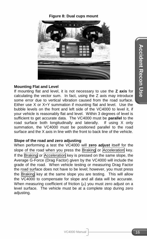
Figure 8: Dual cups mount
Mounting Flat and Level If mounting flat and level, it is not necessary to use the Z axis for calculating the vector sum. In fact, using the Z axis may introduce some error due to vertical vibration caused from the road surface. Either use X or X+Y summation if mounting flat and level. Use the bubble levels on the front and left side of the VC4000 to level it, if your vehicle is reasonably flat and level. Within 3 degrees of level is sufficient to get accurate data. The VC4000 must be parallel to the road surface both longitudinally and laterally. If using X only summation, the VC4000 must be positioned parallel to the road surface and the X axis in line with the front to back line of the vehicle. Slope of the road and zero adjusting When performing a test the VC4000 will zero adjust itself for the
slope of the road when you press the Braking or Acceleration key.
If the Braking or Acceleration key is pressed on the same slope, the
Average G-Force (Drag Factor) given by the VC4000 will include the grade of the road. When vehicle testing or measuring Drag Factor the road surface does not have to be level; however, you must press
the Braking key at the same slope you are testing. This will allow
the VC4000 to compensate for slope and all data will be accurate.
When measuring coefficient of friction () you must zero adjust on a level surface. The vehicle must be at a complete stop during zero adjusting.
VC4000 Manual 17
Slope A = -0.1 Slope C = +0.1 Zero adjust at point B Do skid test at point A, B or C f = µ = 0.800
Zero adjust at point A Zero adjust a point C Do skid test at point A Do skid test at point C f = µ - slope f = µ + slope -0.8 (-) +0.1 = -0.7 -0.8 (+) -0.1 = -0.9 -0.8 + 0.1 = -0.7 -0.8 – 0.1 = -0.9 VC4000 will display -0.700 Ave G VC4000 will display -0.900 Ave G
Attaching accessories It may be easier to plug in cables before mounting the VC4000. If you do not wish to use the batteries on the VC4000 plug the provided power cord into back of VC4000 and into vehicle's accessory jack if one is available. Plug the external activation connector into VC4000 if you are using it (see page 86 for external activation). Plug in VSI or GPS if needed (PC).
Figure 9: VC4000 back panel
VC4000 Run Storage Memory The VC4000 stores all braking runs to internal flash memory. Eventually the memory will fill up or the number of files will exceed
Ac
cid
en
t Re
co
n U
se
VC4000 Manual 18
9,999. When this happens you will have to clear memory. The display will prompt you to clear memory after the error message appears. You should clear run data memory periodically to ensure data storage is successful. To clear memory, press the CLEAR / NO key from the “READY” screen and follow the prompts. Monitor and acceleration runs can store to internal flash memory or use Data Streaming. (PC) Data Streaming sends the data directly to Profile without storing it in flash memory first. It has a sample rate of 100Hz and can run for up to 24 hours. Use Profile and click on the menu “Import/Data Streaming” to use this feature. See Profile help or Profile manual for more details. (PC) The VC4000PC includes an SD flash memory card on which to store run data. To transfer runs onto the SD flash memory card follow these steps:
1. From the “READY” screen, press the Tools key.
2. Scroll to SD Card Options and press ENTER / YES . 3. Select Copy All Runs and press ENTER / YES . 4. Press CLEAR / NO twice to get back to the READY screen.
All runs in the VC4000PC memory will be copied onto the SD card. The runs will remain in the VC4000PC memory until you delete them. A typical 1GB SD card will hold over 200,000 runs.
The most common use of the VC4000 for an accident reconstructionists is to measure Drag Factor. In the VC4000
Average Gx is the drag factor if you pressed the Braking key on
the same slope as the accident scene.
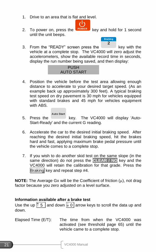
1. Drive to the area where you want to take a measurement.
2. To power on, press the POWER key and hold for 1 second until the unit beeps.
3. From the “READY” screen press the 2
Braking
key with the vehicle at a complete stop. The VC4000 will zero adjust the
Measuring Drag Factor
VC4000 Manual 19
accelerometers, show the available record time in seconds, display the run number being saved, and then display:
4. Position the vehicle before the scene of the accident
allowing enough distance to accelerate to your desired target speed. (As an example back up approximately 300 feet). A typical braking test speed on dry pavement is 30 mph for vehicles equipped with standard brakes and 45 mph for vehicles equipment with ABS.
5. Press the Auto Start
key. The VC4000 will display 'Auto-Start-Ready' and the current G reading.
6. Accelerate the car to the desired initial braking speed. After
reaching the desired initial braking speed, hit the brakes hard and fast, applying maximum brake pedal pressure until the vehicle comes to a complete stop.
7. If you wish to do another skid test on the same slope (in the
same direction) do not press the CLEAR / NO key and the VC4000 will retain the calibration for that grade. Press the “Braking” key and repeat step #4.
When testing the performance of a vehicles braking system, perform the tests on a flat and level surface. An optional brake pedal activation switch is available if required.
1. Drive to an area that is flat and level.
2. To power on, press the POWER key and hold for 1 second until the unit beeps.
PUSH AUTO START
Testing Brake Performance
Ac
cid
en
t Re
co
n U
se
VC4000 Manual 20
3. From the “READY” screen press the 2
Braking
key with the vehicle at a complete stop. The VC4000 will zero adjust the accelerometers, show the available record time in seconds, display the run number being saved, and then display:
4. Position the vehicle before the test area allowing enough
distance to accelerate to your desired target speed. (As an example back up approximately 300 feet). A typical braking test speed on dry pavement is 30 mph for vehicles equipped with standard brakes and 45 mph for vehicles equipment with ABS.
5. Press the Auto Start
key. The VC4000 will display 'Auto-Start-Ready' and the current G reading.
6. Accelerate the car to the desired initial braking speed. After
reaching the desired initial braking speed, hit the brakes hard and fast, applying maximum brake pedal pressure until the vehicle comes to a complete stop.
7. If you wish to do another skid test on the same slope (in the
same direction) do not press the CLEAR / NO key and the VC4000 will retain the calibration for that grade. Press the
Braking key and repeat step #4.
Drag factor (f) = coefficient of friction () ± the slope. If you wish to
measure on a slope you must zero adjust on a flat and level surface.
PUSH AUTO START
Measuring Coefficient of Friction
VC4000 Manual 21
1. Drive to an area that is flat and level.
2. To power on, press the POWER key and hold for 1 second until the unit beeps.
3. From the “READY” screen press the 2
Braking
key with the vehicle at a complete stop. The VC4000 will zero adjust the accelerometers, show the available record time in seconds, display the run number being saved, and then display:
4. Position the vehicle before the test area allowing enough
distance to accelerate to your desired target speed. (As an example back up approximately 300 feet). A typical braking test speed on dry pavement is 30 mph for vehicles equipped with standard brakes and 45 mph for vehicles equipment with ABS.
5. Press the Auto Start
key. The VC4000 will display 'Auto-Start-Ready' and the current G reading.
6. Accelerate the car to the desired initial braking speed. After
reaching the desired initial braking speed, hit the brakes hard and fast, applying maximum brake pedal pressure until the vehicle comes to a complete stop.
7. If you wish to do another skid test on the same slope (in the
same direction) do not press the CLEAR / NO key and the VC4000 will retain the calibration for that grade. Press the
Braking key and repeat step #4.
NOTE: The Average Gx will be the Coefficient of friction (), not drag factor because you zero adjusted on a level surface. Information available after a brake test
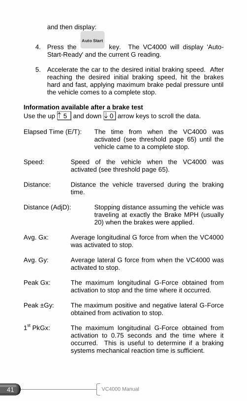
Use the up 5 and down 0 arrow keys to scroll the data up and
down. Elapsed Time (E/T): The time from when the VC4000 was
activated (see threshold page 65) until the vehicle came to a complete stop.
PUSH AUTO START
Ac
cid
en
t Re
co
n U
se
VC4000 Manual 22
Speed: Speed of the vehicle when the VC4000 was activated (see threshold page 65).
Distance: Distance the vehicle traversed during the braking
time. Avg. Gx*: Average longitudinal G force from when the VC4000
was activated to stop. Avg. Gy: Average lateral G force from when the VC4000 was
activated to stop. Peak Gx: The maximum longitudinal G-Force obtained from
activation to stop and the time where it occurred. Peak Gy: The maximum positive and negative lateral G-Force
obtained from activation to stop. Reaction Time (R/T): The time from external trigger to the G-
Threshold. (Shows only if externally triggered)
R/T Dist: The distance traveled during the reaction
time. (Shows only if externally triggered) G(x.x): The instantaneous G-Force at the corresponding
time.
Graphs: Press the Graph/Data key to display graphs of the
run. Press Speed, Distance, G-Force, or Sensor. Press the same key again to scroll through multiple graphs, such as G-Force or Sensor.
* The VC4000's Average G force (Drag Factor) is calculated by summing the G values and dividing by the number of samples. This will give the same result as using velocity and time. While reviewing the data after a braking test if the braking key is pressed the VC4000 will start a new braking test using the zero
reference established the last time the Braking key was pressed
from the “READY” screen.
VC4000 Manual 23
Since the VC4000PC has a selectable G range of 2 or 6 G’s it can be used for low speed impact testing. The range applies to all 3 axis’s so all axes are set to either the 2 G range or the 6 G range. The accelerometers accuracy is degraded slightly when in the 6 G range so speed and distance calculations might not be as accurate. A higher sample rate may also be helpful for low speed impacts. Choose 500Hz or 1000Hz. When using 500Hz sample rate the number of sensors besides the internal accelerometers you can monitor is limited to 13, and 1000Hz is limited to 10 extra sensors. To use the 6G range for the accelerometers and 1000Hz sample rate:
1. Press the Tools key
2. Scroll to Setup and press ENTER / YES 3. Scroll down to Accelerometer… and press ENTER / YES 4. Scroll to Accel Range and press ENTER / YES 5. Choose 6G and press ENTER / YES 6. Scroll to Sample Rate and press ENTER / YES 7. Choose 500 or 1000Hz and press ENTER / YES 8. Press CLEAR / NO twice to get back to the READY screen
Or use Profile to change the accelerometer range. Brake Mode, Crash Mode, Acceleration Mode or Monitor may be used for these tests. Using Crash Mode Crash mode automatically changes the VC4000PC setup to:
Pitch/roll factors = 0
G Range = 6g
Sample rate = 1000
GPS port = port 1
G-Threshold = 4xG-Threshold up to 4G Any GPS or VSI sensors that are turned on will still be recorded. Only the above changes are made during the crash mode. When the test is finished Setup is restored to how it was previously. Up to 10 extra sensors can be turned on and recorded using GPS Speed and VSI sensors. The VC4000PC will record at least one
Low Speed Impacts (PC)
Ac
cid
en
t Re
co
n U
se
VC4000 Manual 24
second before impact (4xG-Threshold) and up to 30 seconds after impact. See Tools/Crash Mode on page 51 for more information.
1. Drive to the area where you want to take a measurement, or close, where the slope is the same.
2. To power on, press the POWER key and hold for 1 second until the unit beeps.
3. From the “READY” screen press the Tools key, then select
Crash Mode with the vehicle at a complete stop. The VC4000 will zero adjust the accelerometers, show the available record time in seconds, display the run number being saved, and then display:
4. Accelerate the car to the desired initial speed. After
reaching that speed, trigger the VC4000 using the external trigger or it will activate when it impacts an object and generates 4xG-Threshold or more.
Using Monitor
1. Drive to the area where you want to take a measurement, or close, where the slope is the same.
2. To power on, press the POWER key and hold for 1 second until the unit beeps.
3. From the “READY” screen press the Tools key, then select
Monitor, then G-Force. 4. The display will show:
5. With the vehicle at a complete stop press ENTER / YES.
The VC4000PC will zero adjust the accelerometers, show the available record time in seconds, display the run number being saved, and then display accelerometer data.
6. Perform your test. Press CLEAR / NO to stop saving data.
AUTO START READY
SAVE IN FILE MEMORY? DEPRESS YES or NO
VC4000 Manual 25
Using Brake Mode NOTE: The VC4000PC in brake mode will stop recording data when the acceleration is positive again. So during the impact if the accelerometer senses positive acceleration it will end the test. In brake mode the sample rate is always 100Hz.
1. Drive to the area where you want to take a measurement, or close, where the slope is the same.
2. To power on, press the POWER key and hold for 1 second until the unit beeps.
3. From the “READY” screen press the 2
Braking
key with the vehicle at a complete stop. The VC4000 will zero adjust the accelerometers, show the available record time in seconds, display the run number being saved, and then display:
4. Press the Auto Start
key. The VC4000PC will display 'Auto-Start-Ready' and the current G reading.
5. Accelerate the car to the desired initial braking speed. After
reaching the desired initial braking speed, trigger the VC4000PC using the external trigger or tap the brakes hard enough to break the G-Threshold (0.200 default). Then impact the object.
NOTE: Be sure to set the G Range back to 2G for other types of testing so speed and distance are more accurate.
If you are testing a motorcycle or large truck that decelerates by more than the default 0.200G threshold when shifting or lifting from the accelerator, to avoid false triggering of your braking run, you may
press the Auto Start key any time after zero adjusting. For example,
you may press Auto Start after the vehicle has reached the desired
braking speed and before applying the brakes. If it’s not possible to
PUSH AUTO START
Avoiding False Triggering
Ac
cid
en
t Re
co
n U
se
VC4000 Manual 26
press a key while moving, increase the G-Threshold to 0.300. See Setup, G-Threshold on page 65. The acceleration mode may be used also. Perform a timed test for 10 seconds or the desired time to complete the test. See Acceleration testing on the next page.
The Grade, or Slope, of the road can be very accurately measured using the VC4000. Use the built in Measure Slope tool to measure the slope in Percent Grade and in Degrees. Measure the slope
1. Drive to the slope you want to measure, facing directly uphill.
2. Press the Tools key. Scroll to the bottom of the list,
Measure Slope and press ENTER / YES.
3. With the vehicle at a complete stop press the Auto Start key.
The VC4000 will zero adjust the accelerometers then show “Position Downhill”.
4. Now turn the vehicle 180 degrees so it is facing directly
downhill and press the Auto Start key again. The VC4000
will read the acceleration then display the Slope values.
Measuring Slope
VC4000 Manual 27
The VC4000 can be used to measure to a preset Time, Speed or Distance. This is useful for:
1. Measuring time and speed from a stop sign to a preset distance at an accident scene in an intersection.
2. Measuring time and distance to a preset speed. 3. Measuring passing time and distance from a preset speed to
a preset speed. To perform a preset distance test
1. Drive to the area where you want to take a measurement, where the slope is the consistent.
2. To power on, press the POWER key and hold for 1 second until the unit beeps.
3. From the “READY” screen press the 1
Acceleration
key with the vehicle at a complete stop. The VC4000 will zero adjust the accelerometers, show the available record time in seconds, display the run number being saved, and then display:
4. Choose one of the presets shown or choose Custom. For
Custom, scroll down to Distance and press ENTER / YES . Type in the distance in feet or meters and press ENTER / YES.
5. The VC4000 will display 'Auto-Start-Ready' and the current
G reading. 6. Accelerate the vehicle until the VC4000 beeps indicating it
has reached the preset distance.
Acceleration Testing
0-30 mph 0-60 mph 0-80 mph 0-100 ft 0-300 ft 0-5 sec Custom AutoStart 1/4 mile
Ac
cid
en
t Re
co
n U
se
VC4000 Manual 28
7. For a custom test, if you wish to do another test on the same slope (in the same direction) do not press the CLEAR / NO key and the VC4000 will retain the calibration for that grade
and use the same custom distance. Press the Acceleration
key, select Repeat Last Run and repeat step #5. To perform a preset speed test
1. Drive to the area where you want to take a measurement, where the slope is the consistent.
2. To power on, press the POWER key and hold for 1 second until the unit beeps.
3. From the “READY” screen press the 1
Acceleration
key with the vehicle at a complete stop. The VC4000 will zero adjust the accelerometers, show the available record time in seconds, display the run number being saved, and then display:
4. Choose one of the presets shown or choose Custom. For
Custom, scroll down to Speed and press ENTER / YES . 5. Type in the “START FROM” speed in mph or kph and press
ENTER / YES. Then type in the “UP TO” speed and press ENTER / YES.
6. The VC4000 will display 'Auto-Start-Ready' and the current
G reading. 7. Accelerate the vehicle until the VC4000 beeps indicating it
has reached the preset speed.
8. For a custom test, if you wish to do another test on the same slope (in the same direction) do not press the CLEAR / NO key and the VC4000 will retain the calibration for that grade
and use the same custom speed. Press the Acceleration
key, select Repeat Last Run and repeat step #6.
0-30 mph 0-60 mph 0-80 mph 0-100 ft 0-300 ft 0-5 sec Custom AutoStart 1/4 mile
VC4000 Manual 29
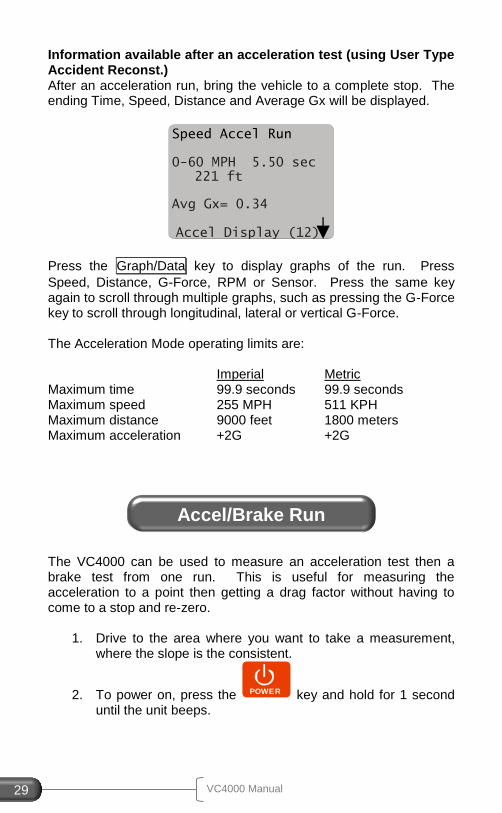
Information available after an acceleration test (using User Type Accident Reconst.) After an acceleration run, bring the vehicle to a complete stop. The ending Time, Speed, Distance and Average Gx will be displayed.
Press the Graph/Data key to display graphs of the run. Press
Speed, Distance, G-Force, RPM or Sensor. Press the same key again to scroll through multiple graphs, such as pressing the G-Force key to scroll through longitudinal, lateral or vertical G-Force. The Acceleration Mode operating limits are: Imperial Metric Maximum time 99.9 seconds 99.9 seconds Maximum speed 255 MPH 511 KPH Maximum distance 9000 feet 1800 meters Maximum acceleration +2G +2G
The VC4000 can be used to measure an acceleration test then a brake test from one run. This is useful for measuring the acceleration to a point then getting a drag factor without having to come to a stop and re-zero.
1. Drive to the area where you want to take a measurement, where the slope is the consistent.
2. To power on, press the POWER key and hold for 1 second until the unit beeps.
Speed Accel Run
0-60 MPH 5.50 sec 221 ft
Avg Gx= 0.34
Accel Display (12)
Accel/Brake Run
Ac
cid
en
t Re
co
n U
se
VC4000 Manual 30
3. From the “READY” screen press the Tools key then select
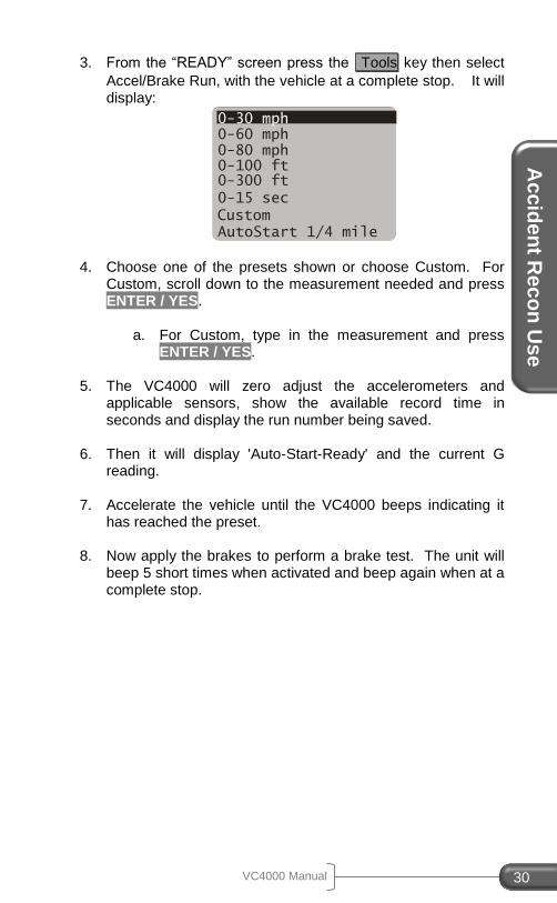
Accel/Brake Run, with the vehicle at a complete stop. It will display:
4. Choose one of the presets shown or choose Custom. For Custom, scroll down to the measurement needed and press ENTER / YES.
a. For Custom, type in the measurement and press
ENTER / YES.
5. The VC4000 will zero adjust the accelerometers and applicable sensors, show the available record time in seconds and display the run number being saved.
6. Then it will display 'Auto-Start-Ready' and the current G reading.
7. Accelerate the vehicle until the VC4000 beeps indicating it has reached the preset.
8. Now apply the brakes to perform a brake test. The unit will beep 5 short times when activated and beep again when at a complete stop.
0-30 mph 0-60 mph 0-80 mph 0-100 ft 0-300 ft
0-15 sec
Custom AutoStart 1/4 mile
VC4000 Manual 31
4. TRANSIT USE
This section gives specific instructions on how to use the VC4000 for Transit Bus testing.
User Type When you first receive your VC4000 the User Type will be “General” which displays all available data. You should change this setting to “Transit” User Type. This will show all the data necessary for the typical transit vehicle brake test. To change the User Type to Transit, follow these steps:
1. Press the Tools key.
2. Scroll to Setup and press ENTER / YES . 3. Scroll down to User Type and press ENTER / YES . 4. Scroll up to Transit and press ENTER / YES . 5. Press CLEAR / NO to get back to the READY screen.
Or use Profile to change the setup in the VC4000 from your PC:
1. Start the Profile program 2. Connect the VC4000 to your computer 3. Turn on the VC4000 4. In Profile, Click on the VC4000 Setup icon (or Tools/VC4000
Setup) 5. Profile will connect and retrieve the VC4000 setup 6. Click the User Type drop down box 7. Select Transit. 8. Click the “Send Setup” key
ALL settings can be changed using Profile. Not all settings can be changed using the VC4000 keypad.
Initial Setup
Tra
ns
it Use
VC4000 Manual 32
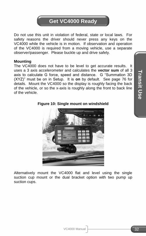
Do not use this unit in violation of federal, state or local laws. For safety reasons the driver should never press any keys on the VC4000 while the vehicle is in motion. If observation and operation of the VC4000 is required from a moving vehicle, use a separate observer/passenger. Please buckle up and drive safely. Mounting The VC4000 does not have to be level to get accurate results. It uses a 3 axis accelerometer and calculates the vector sum of all 3 axis to calculate G force, speed and distance. G “Summation 3D (XYZ)” must be on in Setup. It is on by default. See page 76 for details. Mount the VC4000 so the display is roughly facing the back of the vehicle, or so the x-axis is roughly along the front to back line of the vehicle.
Figure 10: Single mount on windshield
Alternatively mount the VC4000 flat and level using the single suction cup mount or the dual bracket option with two pump up suction cups.
Get VC4000 Ready
VC4000 Manual 33
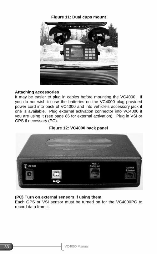
Figure 11: Dual cups mount
Attaching accessories It may be easier to plug in cables before mounting the VC4000. If you do not wish to use the batteries on the VC4000 plug provided power cord into back of VC4000 and into vehicle's accessory jack if one is available. Plug external activation connector into VC4000 if you are using it (see page 86 for external activation). Plug in VSI or GPS if necessary (PC).
Figure 12: VC4000 back panel
(PC) Turn on external sensors if using them Each GPS or VSI sensor must be turned on for the VC4000PC to record data from it.
Tra
ns
it Use
VC4000 Manual 34
1. Press the Tools key
2. Scroll to Setup and press ENTER / YES 3. Scroll down to Sensors… and press ENTER / YES 4. Choose OBDII Sensors or GPS Sensors and press ENTER /
YES 5. See Setup, Sensors on page 73 for details on each sensor 6. Press CLEAR / NO twice to get back to the READY screen
Or use Profile to change the setup in the VC4000 from your PC:
1. Start the Profile program 2. Connect the VC4000 to your computer 3. Turn on the VC4000 4. In Profile, Click on the VC4000 Setup icon (or Tools/VC4000
Setup) 5. Profile will connect and retrieve the VC4000 setup 6. Turn on the sensors using the tabs for each section 7. Click the “Send Setup” button
VC4000 Run Storage Memory The VC4000 stores all braking runs to internal flash memory. Eventually the memory will fill up or the number of files will exceed 65,535. When this happens you will have to clear memory. The display will prompt you to clear memory after the error message appears. You should clear run data memory periodically to ensure data storage is successful. To clear memory, press the CLEAR / NO key from the “READY” screen and follow the prompts. Monitor and acceleration runs can store to internal flash memory or use Data Streaming. (PC) Data Streaming sends the data directly to Profile without storing it in flash memory first. It has a sample rate of 100Hz and can run for up to 24 hours. Use Profile and click on the menu “Import/Data Streaming” to use this feature. See Profile help or Profile manual for more details. (PC) The VC4000PC includes an SD flash memory card on which to store run data. To transfer runs onto the SD flash memory card follow these steps:
1. From the “READY” screen, press the Tools key.
2. Scroll to SD Card Options and press ENTER / YES . 3. Select Copy All Runs and press ENTER / YES . 4. Press CLEAR / NO twice to get back to the READY screen.
VC4000 Manual 35
All runs in the VC4000PC memory will be copied onto the SD card. The runs will remain in the VC4000PC memory until you delete them. A typical 1GB SD card will hold over 200,000 runs.
When testing the performance of a vehicles braking system, perform the tests on a flat and level surface. An optional brake pedal activation switch is available if required.
1. Drive to an area that is flat and level. Connect applicable sensors and activation switch.
2. To power on, press the POWER key and hold for 1 second until the unit beeps.
3. From the “READY” screen press the 2
Braking
key with the vehicle at a complete stop. The VC4000 will zero adjust the accelerometers and applicable sensors, show the available record time in seconds, display the run number being saved,
and then display: 4. Position the vehicle before the test area allowing enough
distance to accelerate to your desired target speed. (As an example back up approximately 300 feet). A typical braking test speed on dry pavement is 20 mph.
5. Press the Auto Start
key. The VC4000 will display 'Auto-Start-Ready' and the current G reading.
6. Accelerate the car to the desired initial braking speed. After
reaching the desired initial braking speed, hit the brakes hard and fast, applying maximum brake pedal pressure until the vehicle comes to a complete stop.
PUSH AUTO START
Testing Brake Performance
Tra
ns
it Use
VC4000 Manual 36
Information available after a brake test
Use the up 5 and down 0 arrow keys to scroll the data.
Elapsed Time (E/T): The time from when the VC4000 was
activated (see threshold page 65) until the vehicle came to a complete stop.
Speed: Speed of the vehicle when the VC4000 was
activated (see threshold page 65). Distance: Distance the vehicle traversed during the braking
time. Distance (AdjD): Stopping distance assuming the vehicle was
traveling at the target braking speed (usually 20 or 60) when the brakes were applied.
Avg. Gx: Average longitudinal G force from when the VC4000
was activated to stop. Peak Gx: The maximum longitudinal G-Force obtained from
activation to stop and the time where it occurred. 1
st PkGx: The maximum longitudinal G-Force obtained from
activation to 0.75 seconds and the time where it occurred. This is useful to determine if a braking systems mechanical reaction time is sufficient.
Reaction Time (R/T): The time from external trigger to the G-
Threshold. (Shows only if externally triggered)
R/T Dist: The distance traveled during the reaction time.
(Shows only if externally triggered)
Graphs: Press the Graph/Data key to display graphs of the
run. Press Speed, Distance, G-Force, or Sensor (PC). Press the same key again to scroll through multiple graphs, such as G-Force.
While reviewing the data after a braking test if the braking key is pressed the VC4000 will start a new braking test using the zero
reference established the last time the Braking key was pressed
from the “READY” screen.
VC4000 Manual 37
5. ENGINEERING USE
This section gives specific instructions on how to use the VC4000 for General and Engineering use.
User Type When you first receive your VC4000 the User Type will be set “General” which displays all available data. To limit the displayed data choose one of the other user types. See User Types in Setup for more information.
Do not use this unit in violation of federal, state or local laws. For safety reasons the driver should never press any keys on the VC4000 while the vehicle is in motion. If observation and operation of the VC4000 is required from a moving vehicle, use a separate observer/passenger. Please buckle up and drive safely. Mounting The VC4000 does not have to be level to get accurate results. It uses a 3 axis accelerometer and calculates the vector sum of all 3 axis to calculate G force, speed and distance. G “Summation 3D (XYZ)” must be on in Setup. It is on by default. See page 76 for details. Mount the VC4000 so the display is roughly facing the back of the vehicle, or so the x-axis is roughly along the front to back line of the vehicle.
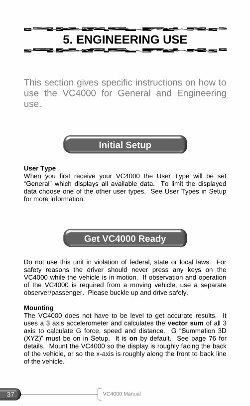
Initial Setup
Get VC4000 Ready
En
gin
ee
ring
Us
e
VC4000 Manual 38
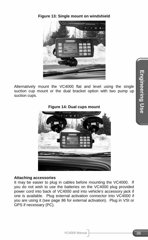
Figure 13: Single mount on windshield
Alternatively mount the VC4000 flat and level using the single suction cup mount or the dual bracket option with two pump up suction cups.
Figure 14: Dual cups mount
Attaching accessories It may be easier to plug in cables before mounting the VC4000. If you do not wish to use the batteries on the VC4000 plug provided power cord into back of VC4000 and into vehicle's accessory jack if one is available. Plug external activation connector into VC4000 if you are using it (see page 86 for external activation). Plug in VSI or GPS if necessary (PC).
VC4000 Manual 39
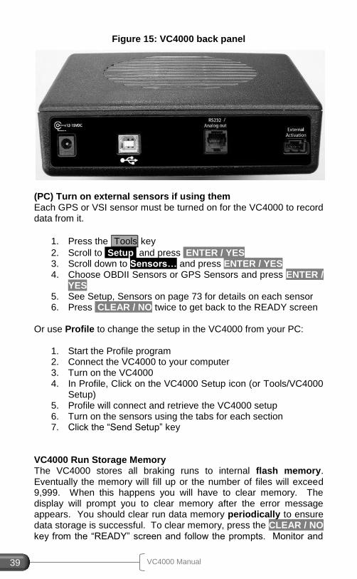
Figure 15: VC4000 back panel
(PC) Turn on external sensors if using them Each GPS or VSI sensor must be turned on for the VC4000 to record data from it.
1. Press the Tools key
2. Scroll to Setup and press ENTER / YES 3. Scroll down to Sensors… and press ENTER / YES 4. Choose OBDII Sensors or GPS Sensors and press ENTER /
YES 5. See Setup, Sensors on page 73 for details on each sensor 6. Press CLEAR / NO twice to get back to the READY screen
Or use Profile to change the setup in the VC4000 from your PC:
1. Start the Profile program 2. Connect the VC4000 to your computer 3. Turn on the VC4000 4. In Profile, Click on the VC4000 Setup icon (or Tools/VC4000
Setup) 5. Profile will connect and retrieve the VC4000 setup 6. Turn on the sensors using the tabs for each section 7. Click the “Send Setup” key
VC4000 Run Storage Memory The VC4000 stores all braking runs to internal flash memory. Eventually the memory will fill up or the number of files will exceed 9,999. When this happens you will have to clear memory. The display will prompt you to clear memory after the error message appears. You should clear run data memory periodically to ensure data storage is successful. To clear memory, press the CLEAR / NO key from the “READY” screen and follow the prompts. Monitor and
En
gin
ee
ring
Us
e
VC4000 Manual 40
acceleration runs can store to internal flash memory or use Data Streaming. (PC) Data Streaming sends the data directly to Profile without storing it in flash memory first. It has a sample rate of 100Hz and can run for up to 24 hours. Use Profile and click on the menu “Import/Data Streaming” to use this feature. See Profile help or Profile manual for more details. (PC) The VC4000PC includes an SD flash memory card on which to store run data. To transfer runs onto the SD flash memory card follow these steps:
1. From the “READY” screen, press the Tools key.
2. Scroll to SD Card Options and press ENTER / YES . 3. Select Copy All Runs and press ENTER / YES . 4. Press CLEAR / NO twice to get back to the READY screen.
All runs in the VC4000PC memory will be copied onto the SD card. The runs will remain in the VC4000PC memory until you delete them. A typical 1GB SD card will hold over 200,000 runs.
When testing the performance of a vehicles braking system, perform the tests on a flat and level surface. An optional brake pedal activation switch is available if required.
1. Drive to an area that is flat and level. Connect applicable sensors and activation switch.
2. To power on, press the POWER key and hold for 1 second until the unit beeps.
3. From the “READY” screen press the 2
Braking
key with the vehicle at a complete stop. The VC4000 will zero adjust the accelerometers and applicable sensors, show the available record time in seconds, display the run number being saved,
PUSH AUTO START
Testing Brake Performance
VC4000 Manual 41
and then display:
4. Press the Auto Start
key. The VC4000 will display 'Auto-Start-Ready' and the current G reading.
5. Accelerate the car to the desired initial braking speed. After
reaching the desired initial braking speed, hit the brakes hard and fast, applying maximum brake pedal pressure until the vehicle comes to a complete stop.
Information available after a brake test
Use the up 5 and down 0 arrow keys to scroll the data.
Elapsed Time (E/T): The time from when the VC4000 was
activated (see threshold page 65) until the vehicle came to a complete stop.
Speed: Speed of the vehicle when the VC4000 was
activated (see threshold page 65). Distance: Distance the vehicle traversed during the braking
time. Distance (AdjD): Stopping distance assuming the vehicle was
traveling at exactly the Brake MPH (usually 20) when the brakes were applied.
Avg. Gx: Average longitudinal G force from when the VC4000
was activated to stop. Avg. Gy: Average lateral G force from when the VC4000 was
activated to stop. Peak Gx: The maximum longitudinal G-Force obtained from
activation to stop and the time where it occurred. Peak ±Gy: The maximum positive and negative lateral G-Force
obtained from activation to stop. 1
st PkGx: The maximum longitudinal G-Force obtained from
activation to 0.75 seconds and the time where it occurred. This is useful to determine if a braking systems mechanical reaction time is sufficient.

En
gin
ee
ring
Us
e
VC4000 Manual 42
Reaction Time (R/T): The time from external trigger to the G-Threshold. (Shows only if externally triggered)
R/T Dist: The distance traveled during the reaction time.
(Shows only if externally triggered)
Graphs: Press the Graph/Data key to display graphs of the
run. Press Speed, Distance, G-Force, or Sensor (PC). Press the same key again to scroll through multiple graphs, such as G-Force or Sensor.
While reviewing the data after a braking test if the braking key is pressed the VC4000 will start a new braking test using the zero
reference established the last time the Braking key was pressed
from the “READY” screen.
The VC4000 can be used to measure to a preset Time, Speed or Distance. QuickSet™ is Vericom’s term for one button programming for the ¼ mile. It assumes a ¼ mile acceleration run so programming to 1320 feet is not necessary. The VC4000 records data at 7 other distance points and 2 speeds (called Waypoints) within the ¼ mile (QuickData™ table). To perform a preset distance test
1. Drive to the area where you want to take a measurement, where the slope is the same.
2. To power on, press the POWER key and hold for 1 second until the unit beeps.
0-30 mph
0-60 mph
0-80 mph
0-100 ft
0-300 ft
0-5 sec
Custom
AutoStart 1/4 mile
Acceleration Testing
VC4000 Manual 43
3. From the “READY” screen press the 1
Acceleration
key with the vehicle at a complete stop. The VC4000 will zero adjust the accelerometers, show the available record time in seconds, display the run number being saved, and then display:
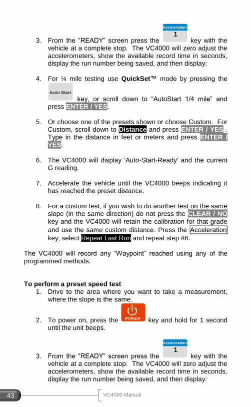
4. For ¼ mile testing use QuickSet™ mode by pressing the
Auto Start
key, or scroll down to “AutoStart 1/4 mile” and press ENTER / YES.
5. Or choose one of the presets shown or choose Custom. For
Custom, scroll down to Distance and press ENTER / YES . Type in the distance in feet or meters and press ENTER / YES.
6. The VC4000 will display 'Auto-Start-Ready' and the current
G reading. 7. Accelerate the vehicle until the VC4000 beeps indicating it
has reached the preset distance.
8. For a custom test, if you wish to do another test on the same slope (in the same direction) do not press the CLEAR / NO key and the VC4000 will retain the calibration for that grade
and use the same custom distance. Press the Acceleration
key, select Repeat Last Run and repeat step #6. The VC4000 will record any “Waypoint” reached using any of the programmed methods. To perform a preset speed test
1. Drive to the area where you want to take a measurement, where the slope is the same.
2. To power on, press the POWER key and hold for 1 second until the unit beeps.
3. From the “READY” screen press the 1
Acceleration
key with the vehicle at a complete stop. The VC4000 will zero adjust the accelerometers, show the available record time in seconds, display the run number being saved, and then display:
En
gin
ee
ring
Us
e
VC4000 Manual 44
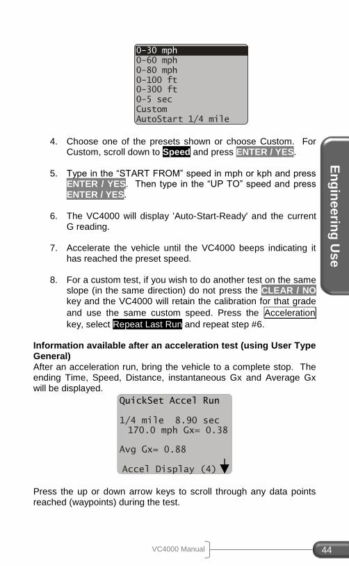
4. Choose one of the presets shown or choose Custom. For Custom, scroll down to Speed and press ENTER / YES.
5. Type in the “START FROM” speed in mph or kph and press
ENTER / YES. Then type in the “UP TO” speed and press ENTER / YES.
6. The VC4000 will display 'Auto-Start-Ready' and the current
G reading. 7. Accelerate the vehicle until the VC4000 beeps indicating it
has reached the preset speed.
8. For a custom test, if you wish to do another test on the same slope (in the same direction) do not press the CLEAR / NO key and the VC4000 will retain the calibration for that grade
and use the same custom speed. Press the Acceleration
key, select Repeat Last Run and repeat step #6. Information available after an acceleration test (using User Type General) After an acceleration run, bring the vehicle to a complete stop. The ending Time, Speed, Distance, instantaneous Gx and Average Gx will be displayed.
Press the up or down arrow keys to scroll through any data points reached (waypoints) during the test.
0-30 mph
0-60 mph
0-80 mph
0-100 ft
0-300 ft
0-5 sec
Custom
AutoStart 1/4 mile
QuickSet Accel Run
1/4 mile 8.90 sec 170.0 mph Gx= 0.38
Avg Gx= 0.88
Accel Display (4)
VC4000 Manual 45
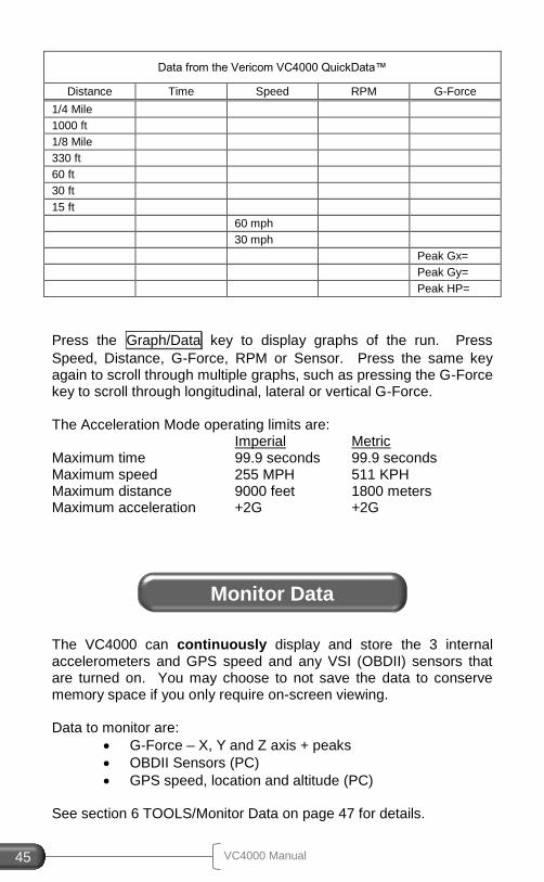
Data from the Vericom VC4000 QuickData™
Distance Time Speed RPM G-Force
1/4 Mile
1000 ft
1/8 Mile
330 ft
60 ft
30 ft
15 ft
60 mph
30 mph
Peak Gx=
Peak Gy=
Peak HP=
Press the Graph/Data key to display graphs of the run. Press
Speed, Distance, G-Force, RPM or Sensor. Press the same key again to scroll through multiple graphs, such as pressing the G-Force key to scroll through longitudinal, lateral or vertical G-Force. The Acceleration Mode operating limits are: Imperial Metric Maximum time 99.9 seconds 99.9 seconds Maximum speed 255 MPH 511 KPH Maximum distance 9000 feet 1800 meters Maximum acceleration +2G +2G
The VC4000 can continuously display and store the 3 internal accelerometers and GPS speed and any VSI (OBDII) sensors that are turned on. You may choose to not save the data to conserve memory space if you only require on-screen viewing. Data to monitor are:
G-Force – X, Y and Z axis + peaks
OBDII Sensors (PC)
GPS speed, location and altitude (PC) See section 6 TOOLS/Monitor Data on page 47 for details.
Monitor Data

To
ols
VC4000 Manual 46
6. TOOLS
This section explains the available tools in the VC4000.
The VC4000 has several tools available. Press the 3
Tools
key to bring up a list of available tools. Below is a list of the tools and a short description of each.
Monitor
Cal. Check Setup Delete Run Print SD Card Options
Accel/Brake Run
Crash Mode
VC4000 Manual 47
Tool Description
Monitor Continuously display Acceleration, GPS data (PC) or OBDII sensors (PC)
Crash Mode (PC)
Saves data 1 second before a high G-Threshold and up to 30 seconds after
Cal. Check Check calibration on internal accelerometers
Setup Change VC4000 Setup including G-Threshold, User type and turn GPS (PC) or VSI (PC) on or off
Delete Run Delete a run from memory
Print Print a single or all runs in memory
SD Card Options (PC)
Copy or erase runs from SD Card
Accel/Brake Run
Perform an acceleration test followed by a brake test without stopping to re-zero
Enter Suffix Adds a suffix letter to the run file when saved using Profile 5
Measure Slope Measure slope of a road in Grade and Degree
The VC4000 can continuously display and store the 3 internal accelerometers and GPS speed, location, altitude and any VSI (OBDII) sensors that are turned on. You may choose to not save the data to conserve memory space if you only require on-screen viewing. Data may also be transmitted directly to Profile (PC). To use the “Data Streaming” feature in Profile, leave the VC4000 at the “READY” screen and in Profile click on “Import/Data Streaming” (PC).
Monitor Data
To
ols
VC4000 Manual 48
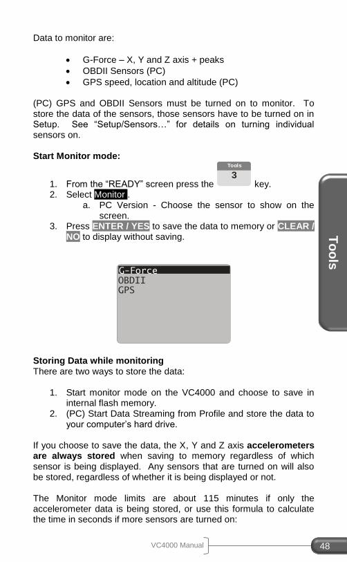
Data to monitor are:
G-Force – X, Y and Z axis + peaks
OBDII Sensors (PC)
GPS speed, location and altitude (PC) (PC) GPS and OBDII Sensors must be turned on to monitor. To store the data of the sensors, those sensors have to be turned on in Setup. See “Setup/Sensors…” for details on turning individual sensors on. Start Monitor mode:
1. From the “READY” screen press the 3
Tools
key. 2. Select Monitor .
a. PC Version - Choose the sensor to show on the screen.
3. Press ENTER / YES to save the data to memory or CLEAR / NO to display without saving.
Storing Data while monitoring There are two ways to store the data:
1. Start monitor mode on the VC4000 and choose to save in internal flash memory.
2. (PC) Start Data Streaming from Profile and store the data to your computer’s hard drive.
If you choose to save the data, the X, Y and Z axis accelerometers are always stored when saving to memory regardless of which sensor is being displayed. Any sensors that are turned on will also be stored, regardless of whether it is being displayed or not. The Monitor mode limits are about 115 minutes if only the accelerometer data is being stored, or use this formula to calculate the time in seconds if more sensors are turned on:
G-Force
GPS OBDII
VC4000 Manual 49
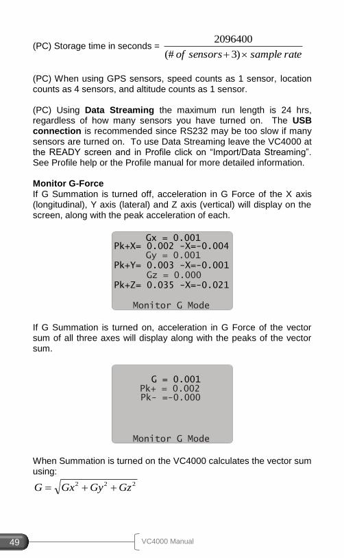
(PC) Storage time in seconds = ratesamplesensorsof )3(#
2096400
(PC) When using GPS sensors, speed counts as 1 sensor, location counts as 4 sensors, and altitude counts as 1 sensor. (PC) Using Data Streaming the maximum run length is 24 hrs, regardless of how many sensors you have turned on. The USB connection is recommended since RS232 may be too slow if many sensors are turned on. To use Data Streaming leave the VC4000 at the READY screen and in Profile click on “Import/Data Streaming”. See Profile help or the Profile manual for more detailed information. Monitor G-Force If G Summation is turned off, acceleration in G Force of the X axis (longitudinal), Y axis (lateral) and Z axis (vertical) will display on the screen, along with the peak acceleration of each.
If G Summation is turned on, acceleration in G Force of the vector sum of all three axes will display along with the peaks of the vector sum.
When Summation is turned on the VC4000 calculates the vector sum using:
222 GzGyGxG
Gx = 0.001
Gy = 0.001
Monitor G Mode
Pk+X= 0.002 -X=-0.004
Pk+Y= 0.003 -X=-0.001
Gz = 0.000 Pk+Z= 0.035 -X=-0.021
G = 0.001
Pk+ = 0.002
Monitor G Mode
Pk- =-0.000
To
ols
VC4000 Manual 50
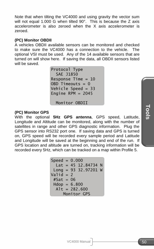
Note that when tilting the VC4000 and using gravity the vector sum will not equal 1.000 G when tilted 90°. This is because the Z axis accelerometer is also zeroed when the X axis accelerometer is zeroed. (PC) Monitor OBDII A vehicles OBDII available sensors can be monitored and checked to make sure the VC4000 has a connection to the vehicle. The optional VSI must be used. Any of the 14 available sensors that are turned on will show here. If saving the data, all OBDII sensors listed will be saved.
(PC) Monitor GPS With the optional 5Hz GPS antenna, GPS speed, Latitude, Longitude and Altitude can be monitored, along with the number of satellites in range and other GPS diagnostic information. Plug the GPS sensor into RS232 port one. If saving data and GPS is turned on, GPS speed will be recorded every sample period and Latitude and Longitude will be saved at the beginning and end of the run. If GPS location and altitude are turned on, tracking information will be recorded every 5Hz, which can be tracked on a map within Profile 5.
Protocol Type
SAE J1850
Response Time = 10
OBD Timeouts = 0
Vehicle Speed = 33
Engine RPM = 2045
Monitor OBDII
Speed = 0.000
Lat = 45 12.84734 N
Long = 93 32.97201 W
Valid = 2
#Sat = 06
Hdop = 6.800
Alt = 282.600
Monitor GPS
VC4000 Manual 51
Display Meaning
Speed GPS speed in MPH or KPH if in Metric mode
Lat Latitude in degrees, minutes.seconds
Long Longitude in degrees, minutes.seconds
Valid GPS quality. 0 = no fix, 1 = non-differential, 2 = differential (WAAS), 6 = estimated
#Sat Number of satellites in use
Hdop Absolute position accuracy in Meters
Alt Altitude in Meters
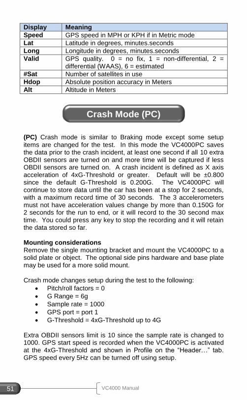
(PC) Crash mode is similar to Braking mode except some setup items are changed for the test. In this mode the VC4000PC saves the data prior to the crash incident, at least one second if all 10 extra OBDII sensors are turned on and more time will be captured if less OBDII sensors are turned on. A crash incident is defined as X axis acceleration of 4xG-Threshold or greater. Default will be ±0.800 since the default G-Threshold is 0.200G. The VC4000PC will continue to store data until the car has been at a stop for 2 seconds, with a maximum record time of 30 seconds. The 3 accelerometers must not have acceleration values change by more than 0.150G for 2 seconds for the run to end, or it will record to the 30 second max time. You could press any key to stop the recording and it will retain the data stored so far. Mounting considerations Remove the single mounting bracket and mount the VC4000PC to a solid plate or object. The optional side pins hardware and base plate may be used for a more solid mount. Crash mode changes setup during the test to the following:
Pitch/roll factors = 0
G Range = 6g
Sample rate = 1000
GPS port = port 1
G-Threshold = 4xG-Threshold up to 4G Extra OBDII sensors limit is 10 since the sample rate is changed to 1000. GPS start speed is recorded when the VC4000PC is activated at the 4xG-Threshold and shown in Profile on the “Header…” tab. GPS speed every 5Hz can be turned off using setup.
Crash Mode (PC)
To
ols
VC4000 Manual 52
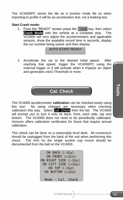
The VC4000PC stores the file as a monitor mode file so when importing to profile it will be an acceleration test, not a braking test. Start Crash mode:
1. From the “READY” screen press the Tools key, then select
Crash Mode with the vehicle at a complete stop. The VC4000 will zero adjust the accelerometers and applicable sensors, show the available record time in seconds, display the run number being saved, and then display:
2. Accelerate the car to the desired initial speed. After
reaching that speed, trigger the VC4000PC using the external trigger or it will activate when it impacts an object and generates ±4xG-Threshold or more.
The VC4000 accelerometer calibration can be checked easily using this tool. No setup changes are necessary when checking calibration this way. Select Cal. Check from the list. The VC4000 will prompt you to turn it onto its back, front, each side, top and bottom. The VC4000 does not need to be periodically calibrated. Vericom offers calibration certificates for those that require annual calibration. This check can be done on a reasonably level desk. All connectors should be unplugged from the back of the unit when performing this check. The Arm for the single suction cup mount should be disconnected from the ball on the VC4000.
AUTO START READY
Cal. Check
ON BACK (-1Gx)
ON FRONT (+1Gx)
ON RIGHT SIDE (-1Gy)
ON LEFT SIDE (+1Gy)
ON TOP (-1Gz)
ON BOTTOM (+1Gz)
Mode – Cal. Check
VC4000 Manual 53
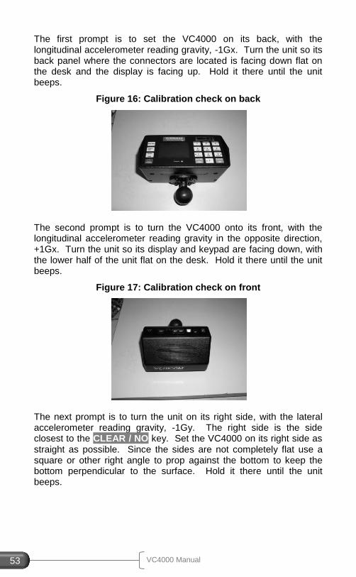
The first prompt is to set the VC4000 on its back, with the longitudinal accelerometer reading gravity, -1Gx. Turn the unit so its back panel where the connectors are located is facing down flat on the desk and the display is facing up. Hold it there until the unit beeps.
Figure 16: Calibration check on back
The second prompt is to turn the VC4000 onto its front, with the longitudinal accelerometer reading gravity in the opposite direction, +1Gx. Turn the unit so its display and keypad are facing down, with the lower half of the unit flat on the desk. Hold it there until the unit beeps.
Figure 17: Calibration check on front
The next prompt is to turn the unit on its right side, with the lateral accelerometer reading gravity, -1Gy. The right side is the side closest to the CLEAR / NO key. Set the VC4000 on its right side as straight as possible. Since the sides are not completely flat use a square or other right angle to prop against the bottom to keep the bottom perpendicular to the surface. Hold it there until the unit beeps.
To
ols
VC4000 Manual 54
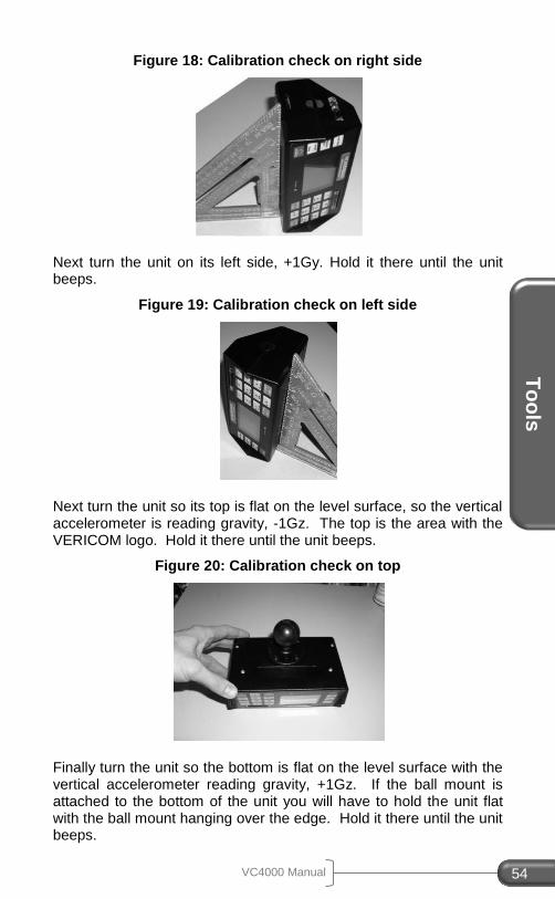
Figure 18: Calibration check on right side
Next turn the unit on its left side, +1Gy. Hold it there until the unit beeps.
Figure 19: Calibration check on left side
Next turn the unit so its top is flat on the level surface, so the vertical accelerometer is reading gravity, -1Gz. The top is the area with the VERICOM logo. Hold it there until the unit beeps.
Figure 20: Calibration check on top
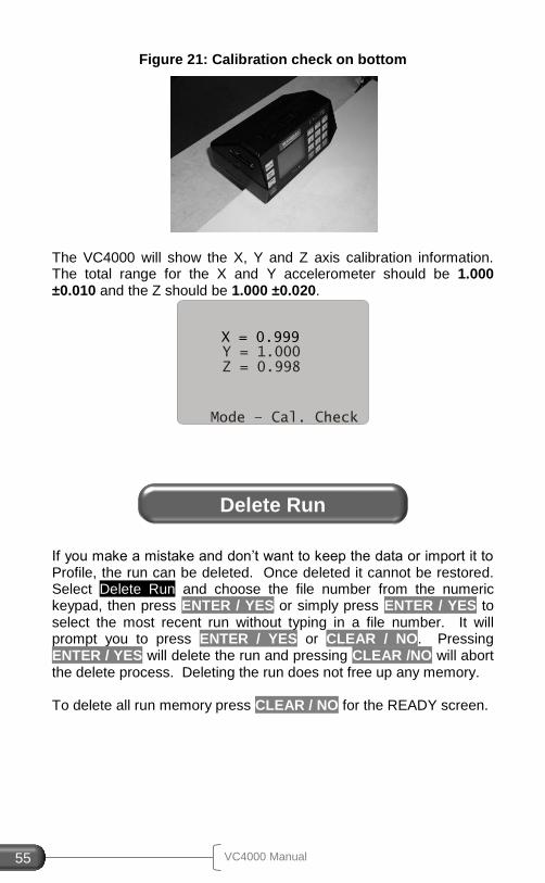
Finally turn the unit so the bottom is flat on the level surface with the vertical accelerometer reading gravity, +1Gz. If the ball mount is attached to the bottom of the unit you will have to hold the unit flat with the ball mount hanging over the edge. Hold it there until the unit beeps.
VC4000 Manual 55
Figure 21: Calibration check on bottom
The VC4000 will show the X, Y and Z axis calibration information. The total range for the X and Y accelerometer should be 1.000 ±0.010 and the Z should be 1.000 ±0.020.
If you make a mistake and don’t want to keep the data or import it to Profile, the run can be deleted. Once deleted it cannot be restored. Select Delete Run and choose the file number from the numeric keypad, then press ENTER / YES or simply press ENTER / YES to select the most recent run without typing in a file number. It will prompt you to press ENTER / YES or CLEAR / NO. Pressing ENTER / YES will delete the run and pressing CLEAR /NO will abort the delete process. Deleting the run does not free up any memory. To delete all run memory press CLEAR / NO for the READY screen.
X = 0.999
Y = 1.000
Mode – Cal. Check
Z = 0.998
Delete Run
To
ols
VC4000 Manual 56
If you purchased Vericom’s portable thermal printer, one run or all the runs stored in memory can be printed on it from the VC4000. The data printed will be the summary information such as Time, Speed, Distance, Average G and Peak G along with a graph of the acceleration vs. time. Connect the printer to one of the RS232 ports using Vericom’s thermal printer to VC4000 cable, which can be identified by a sticker that reads “Connect to Printer” on the RJ12 to Dsub converter end. Use Setup to set the RS232 port to “Printer”. RS232(1) is set for the printer by default. Select Print from the Tools menu, and then choose Print Run or Print All Runs.
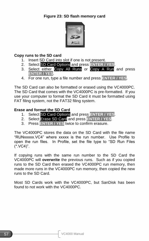
The VC4000PC can copy stored runs onto a Secure Digital Flash Card (SD card). The SD card does not need to be installed into the VC4000PC during testing. It is used for transferring data from your VC4000PC to a computer in lieu of a USB cable or RS232 cable connection. The VC4000PC stores all runs in internal flash memory until you clear them. External flash memory (SD Card) is not fast enough to store the data from the VC4000PC as it’s running. A typical 1GB SD card will hold over 200,000 runs.
Figure 22: SD Card slot
SD Card Options (PC)
VC4000 Manual 57
Figure 23: SD flash memory card
Copy runs to the SD card
1. Insert SD Card into slot if one is not present. 2. Select SD Card Options and press ENTER / YES. 3. Select either Copy All Runs or Copy A Run and press
ENTER / YES. 4. For one run, type a file number and press ENTER / YES.
The SD Card can also be formatted or erased using the VC4000PC. The SD Card that comes with the VC4000PC is pre-formatted. If you use your computer to format the SD Card it must be formatted using FAT filing system, not the FAT32 filing system. Erase and format the SD Card
1. Select SD Card Options and press ENTER / YES. 2. Select Erase SD Card and press ENTER / YES. 3. Press ENTER / YES twice to confirm erasure.
The VC4000PC stores the data on the SD Card with the file name “RUNxxxxx.VC4” where xxxxx is the run number. Use Profile to open the run files. In Profile, set the file type to “SD Run Files (*.VC4)”. If copying runs with the same run number to the SD Card the VC4000PC will overwrite the previous runs. Such as if you copied runs to the SD Card then erased the VC4000PC run memory, then made more runs in the VC4000PC run memory, then copied the new runs to the SD Card. Most SD Cards work with the VC4000PC, but SanDisk has been found to not work with the VC4000PC.
To
ols
VC4000 Manual 58
Perform an acceleration test followed by a brake test without stopping to re-zero. Using the Accel/Brake tool reduces the time it takes to make two tests. The VC4000 will perform the acceleration test first then create a new file number for the subsequent brake test. Internally they will be two separate tests, so Profile will import two separate tests. For example choose 0 – 60mph for the acceleration test then hit the brakes after reaching 60 mph. The acceleration test would be file 1 and the brake test would be file 2. If you set the brake MPH to 60, you will have data for 0 – 60mph and 60 – 0mph from one test but in two separate files.
1. Drive to the area where you want to take a measurement, where the slope is the consistent.
2. To power on, press the POWER key and hold for 1 second until the unit beeps.
3. From the “READY” screen press the Tools key then select
Accel/Brake Run, with the vehicle at a complete stop. It will display:
4. Choose one of the presets shown or choose Custom. For Custom, scroll down to the measurement needed and press ENTER / YES.
a. For Custom, type in the measurement and press
ENTER / YES.
5. The VC4000 will zero adjust the accelerometers and applicable sensors, show the available record time in seconds and display the run number being saved.
Accel/Brake Runs
0-30 mph 0-60 mph 0-80 mph 0-100 ft 0-300 ft
0-15 sec
Custom AutoStart 1/4 mile
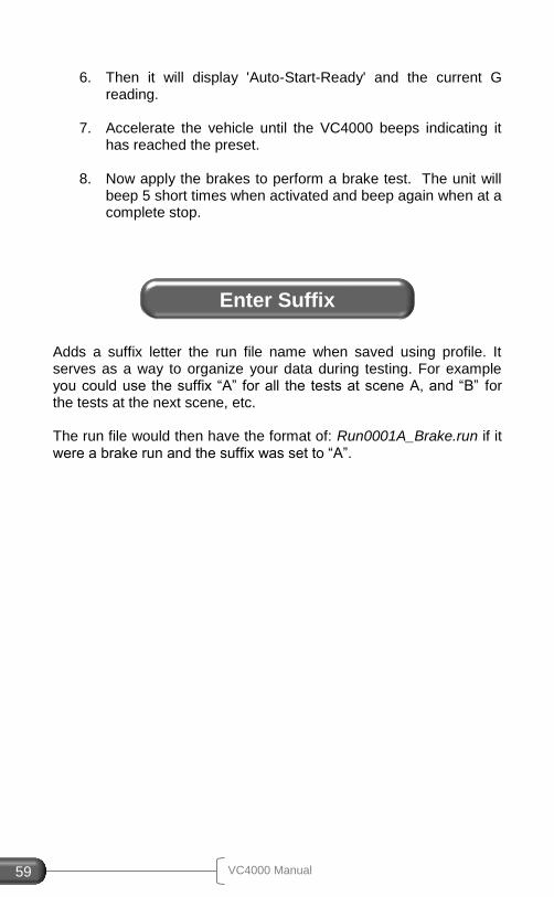
VC4000 Manual 59
6. Then it will display 'Auto-Start-Ready' and the current G
reading.
7. Accelerate the vehicle until the VC4000 beeps indicating it has reached the preset.
8. Now apply the brakes to perform a brake test. The unit will beep 5 short times when activated and beep again when at a complete stop.
Adds a suffix letter the run file name when saved using profile. It serves as a way to organize your data during testing. For example you could use the suffix “A” for all the tests at scene A, and “B” for the tests at the next scene, etc. The run file would then have the format of: Run0001A_Brake.run if it were a brake run and the suffix was set to “A”.
Enter Suffix
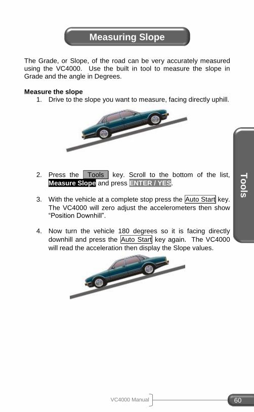
To
ols
VC4000 Manual 60
The Grade, or Slope, of the road can be very accurately measured using the VC4000. Use the built in tool to measure the slope in Grade and the angle in Degrees. Measure the slope
1. Drive to the slope you want to measure, facing directly uphill.
2. Press the Tools key. Scroll to the bottom of the list,
Measure Slope and press ENTER / YES.
3. With the vehicle at a complete stop press the Auto Start key.
The VC4000 will zero adjust the accelerometers then show “Position Downhill”.
4. Now turn the vehicle 180 degrees so it is facing directly
downhill and press the Auto Start key again. The VC4000
will read the acceleration then display the Slope values.
Measuring Slope
VC4000 Manual 61
7. VC4000 SETUP
This section explains the setup options in the VC4000. Each setting is described in detail.
The VC4000 has many settings that can be changed to suit your needs. The unit will operate in default mode without any operator intervention. Usually only the sensors need to be turned on or off. Following is a flowchart to help you navigate to the setting you may want to change. All of these settings can be changed using Profile software as well, and will be easier using Profile since the settings are laid out on forms. Brake Meters can use Profile VC4000 Setup, but will not transfer data.
Figure 24: Profile VC4000 setup window
Setup
VC4000 Manual 62
VC
40
00 S
etu
p
To change setup using the VC4000 keypad, click the 3
Tools
key and select “Setup”. The VC4000 will store the settings when setup is exited and confirm with a message at the bottom of the screen.
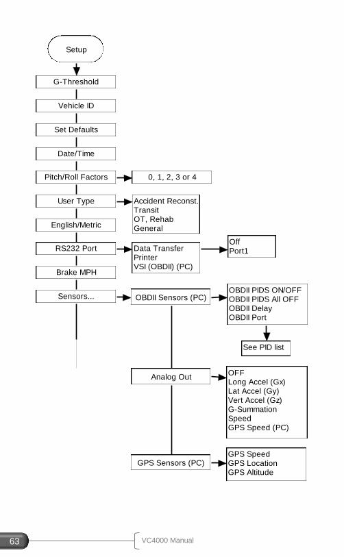
VC4000 Manual 63
Setup
G-Threshold
Vehicle ID
Set Defaults
Date/Time
Pitch/Roll Factors
User Type
0, 1, 2, 3 or 4
Accident Reconst.TransitOT, RehabGeneralEnglish/Metric
RS232 Port
Brake MPH
Sensors...
Data TransferPrinterVSI (OBDII) (PC)
OffPort1
OBDII Sensors (PC)OBDII PIDS ON/OFFOBDII PIDS All OFFOBDII DelayOBDII Port
Analog Out
GPS Sensors (PC)
OFFLong Accel (Gx)Lat Accel (Gy)Vert Accel (Gz)G-SummationSpeedGPS Speed (PC)
GPS SpeedGPS LocationGPS Altitude
See PID list
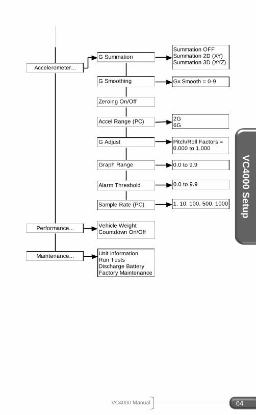
VC4000 Manual 64
VC
40
00 S
etu
p
Accelerometer...
Performance...
Maintenance...
G Summation
G Smoothing
Zeroing On/Off
Accel Range (PC)
G Adjust
Graph Range
Alarm Threshold
Summation OFFSummation 2D (XY)Summation 3D (XYZ)
Gx Smooth = 0-9
2G6G
Vehicle WeightCountdown On/Off
Unit InformationRun TestsDischarge BatteryFactory Maintenance
Pitch/Roll Factors =0.000 to 1.000
0.0 to 9.9
0.0 to 9.9
Sample Rate (PC) 1, 10, 100, 500, 1000
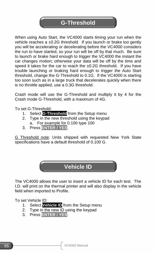
VC4000 Manual 65
When using Auto Start, the VC4000 starts timing your run when the vehicle reaches a ±0.2G threshold. If you launch or brake too gently you will be accelerating or decelerating before the VC4000 considers the run to have started, so your run will be off by that much. Be sure to launch or brake hard enough to trigger the VC4000 the instant the car changes motion; otherwise your data will be off by the time and speed it takes for the car to reach the ±0.2G threshold. If you have trouble launching or braking hard enough to trigger the Auto Start threshold, change the G-Threshold to 0.1G. If the VC4000 is starting too soon such as in a large truck that decelerates quickly when there is no throttle applied, use a 0.3G threshold. Crash mode will use the G-Threshold and multiply it by 4 for the Crash mode G-Threshold, with a maximum of 4G. To set G-Threshold:
1. Select G-Threshold from the Setup menu 2. Type in the new threshold using the keypad
a. For example for 0.100 type 100 3. Press ENTER / YES.
G Threshold note: Units shipped with requested New York State specifications have a default threshold of 0.100 G.
The VC4000 allows the user to insert a vehicle ID for each test. The I.D. will print on the thermal printer and will also display in the vehicle field when imported to Profile. To set Vehicle ID:
1. Select Vehicle ID from the Setup menu 2. Type in the new ID using the keypad 3. Press ENTER / YES.
G-Threshold
Vehicle ID
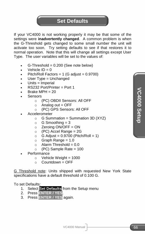
VC4000 Manual 66
VC
40
00 S
etu
p
If your VC4000 is not working properly it may be that some of the settings were inadvertently changed. A common problem is when the G-Threshold gets changed to some small number the unit will activate too soon. Try setting defaults to see if that restores it to normal operation. Note that this will change all settings except User Type. The user variables will be set to the values of:
G-Threshold = 0.200 (See note below) Vehicle ID = 0 Pitch/Roll Factors = 1 (G adjust = 0.9700) User Type = Unchanged Units = Imperial RS232 Port/Printer = Port 1 Brake MPH = 20 Sensors
o (PC) OBDII Sensors: All OFF o Analog out = OFF o (PC) GPS Sensors: All OFF
Accelerometer o G Summation = Summation 3D (XYZ) o G Smoothing = 3 o Zeroing ON/OFF = ON o (PC) Accel Range = 2G o G Adjust = 0.9700 (Pitch/Roll = 1) o Graph Range = 1.0 o Alarm Threshold = 0.0 o (PC) Sample Rate = 100
Performance o Vehicle Weight = 1000 o Countdown = OFF
G Threshold note: Units shipped with requested New York State specifications have a default threshold of 0.100 G. To set Defaults:
1. Select Set Defaults from the Setup menu 2. Press ENTER / YES. 3. Press ENTER / YES again.
Set Defaults
VC4000 Manual 67
All VC4000’s have a date chip that maintains time and date even in the absence of power. It contains a lithium battery supply, which will last a minimum of 10 years. The time and date of each run is stored in memory and then uploaded to Profile and stored in the header of Profile for each run. This is useful if the file numbers do not correlate to the test number because you have had to clear memory after making some tests. At least you have the time of day for a reference point. 1. Select Date/Time from the Setup menu 2. Set the time for your time zone by entering every number,
including zeros. To enter time of 9:00 enter 0, 9, 0, 0. 3. Enter 1 for am or 2 for pm after the digits are entered. 4. Enter the date including zeros. After the date is entered the
VC4000 sets the time and date in memory. 5. Alternatively use Profile to set the time and date to your
computers time and date. CLEAR / NO may be pressed anytime to abort setting the time and date.
Enter the pitch and roll factors. The default is 1 for each. Pitch is the front-to-back tilt, and roll is the side-to-side tilt. If G summation is either 2D (XY) or 3D (XYZ) the VC4000 will use the Gx pitch factor for the adjustment. Gy (roll) and Gz adjust will have no effect.
Date/Time
Pitch/Roll Factors
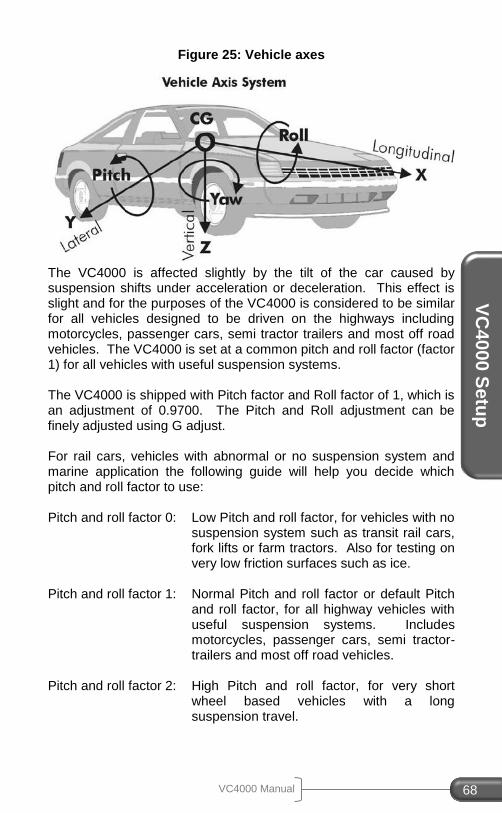
VC4000 Manual 68
VC
40
00 S
etu
p
Figure 25: Vehicle axes
The VC4000 is affected slightly by the tilt of the car caused by suspension shifts under acceleration or deceleration. This effect is slight and for the purposes of the VC4000 is considered to be similar for all vehicles designed to be driven on the highways including motorcycles, passenger cars, semi tractor trailers and most off road vehicles. The VC4000 is set at a common pitch and roll factor (factor 1) for all vehicles with useful suspension systems. The VC4000 is shipped with Pitch factor and Roll factor of 1, which is an adjustment of 0.9700. The Pitch and Roll adjustment can be finely adjusted using G adjust. For rail cars, vehicles with abnormal or no suspension system and marine application the following guide will help you decide which pitch and roll factor to use: Pitch and roll factor 0: Low Pitch and roll factor, for vehicles with no
suspension system such as transit rail cars, fork lifts or farm tractors. Also for testing on very low friction surfaces such as ice.
Pitch and roll factor 1: Normal Pitch and roll factor or default Pitch
and roll factor, for all highway vehicles with useful suspension systems. Includes motorcycles, passenger cars, semi tractor-trailers and most off road vehicles.
Pitch and roll factor 2: High Pitch and roll factor, for very short
wheel based vehicles with a long suspension travel.
VC4000 Manual 69
Pitch and roll factor 3: Very high Pitch and roll factor, for marine or similar application when the bow rises higher that the stern.
Pitch and roll factor 4: Extreme high Pitch and roll factor, for marine
or similar application when the bow rises higher that the stern.
To set Pitch and Roll factors:
1. Select Pitch/Roll Factors from the Setup menu 2. Type a number from 0 to 4 using the keypad 3. Press ENTER / YES.
Changing the user type changes the data that is displayed after a test and when runs are selected from memory. In some cases it will change how the test starts and will change other user settings. Accident Reconstruction: Display – Brake mode:
Reaction Time
Reaction Time distance
Elapsed Time
Speed
Distance
Avg. G or avg. Gx if summation not on
Avg. Gy (only if summation off)
Peak G or Gx and the time it occurred
Peak ± Gy (only if summation off)
G every 0.10 sec.
Display – Acceleration mode:
Time to programmed parameter
Speed to programmed parameter
Distance to programmed parameter
Avg. G or avg. Gx if summation not on
User Type
VC4000 Manual 70
VC
40
00 S
etu
p
Transit: Display – Brake mode:
Reaction Time
Reaction Time distance
Elapsed Time
Speed
Distance
Adjusted Distance to predetermined speed
Avg. G or avg. Gx if summation not on
Avg. Gy (only if summation off)
Peak G or Gx and the time it occurred
1st
Peak Gx and the time it occurred under 0.75 seconds
Display – Acceleration mode:
Time to programmed parameter
Speed to programmed parameter
Distance to programmed parameter
Avg. G or avg. Gx if summation not on OT - Rehab:
Does not zero the accelerometer before a run Display – Brake mode:
Reaction Time
Reaction Time distance
Elapsed Time
Speed
Distance
Display – Acceleration mode:
Time to programmed parameter
Speed to programmed parameter
Distance to programmed parameter
Avg. G or avg. Gx if summation not on General: Display – Brake mode:
Reaction Time
Reaction Time distance
Elapsed Time
Speed
Distance
Adjusted Distance to predetermined speed
Avg. G or avg. Gx if summation not on
VC4000 Manual 71
Avg. Gy (only if summation off)
Peak G or Gx and the time it occurred
Peak ± Gy (only if summation off)
1st
Peak Gx and the time it occurred under 0.75 seconds
G every 0.10 sec
Display – Acceleration mode:
Time to programmed parameter
Speed to programmed parameter
Distance to programmed parameter
Waypoints
Avg. G or avg. Gx if summation not on
Avg. Gy (only if summation off)
Peak G or Gx at time, speed, dist
Peak Gy at time, speed, dist (only if summation off)
Peak HP at time, speed, dist, torque, RPM To set User Type:
1. Select User Type from the Setup menu 2. Select user type 3. Press ENTER / YES.
The VC4000 can give Imperial or metric data for braking or acceleration runs. The Metric data will be displayed in the following units: KPH: Kilometers Per Hour M: Meters Metric acceleration runs are limited to 511 KPH and 1800 meters and the start to stop speed must be 10 KPH apart. The QuickSet™ mode will give distance QuickData™ points in Imperial units and speed in metric. To set Imperial or Metric units:
1. Select Imperial/Metric from the Setup menu 2. Select Imperial or Metric 3. Press ENTER / YES.
Imperial/Metric
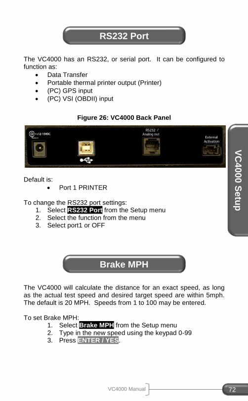
VC4000 Manual 72
VC
40
00 S
etu
p
The VC4000 has an RS232, or serial port. It can be configured to function as:
Data Transfer
Portable thermal printer output (Printer)
(PC) GPS input
(PC) VSI (OBDII) input
Figure 26: VC4000 Back Panel
Default is:
Port 1 PRINTER To change the RS232 port settings:
1. Select RS232 Port from the Setup menu 2. Select the function from the menu 3. Select port1 or OFF
The VC4000 will calculate the distance for an exact speed, as long as the actual test speed and desired target speed are within 5mph. The default is 20 MPH. Speeds from 1 to 100 may be entered. To set Brake MPH:
1. Select Brake MPH from the Setup menu 2. Type in the new speed using the keypad 0-99 3. Press ENTER / YES.
RS232 Port
Brake MPH
VC4000 Manual 73
The VC4000 has several sensors that can be configured. Sensor table
(PC) OBDII sensors o 14 EPA mandated sensors on USA
spec vehicles o Connect using VSI interface
1 Analog output port o Output various sensors (see list) o Connect to other data acquisition
systems
(PC) GPS Sensors o Store position every sample period o Store GPS speed every sample period
(PC) OBDII Sensors
The VC4000PC can monitor and store up to 14 OBDII parameters. There are more parameters available on OBDII but the others are not normally used so for the sake of simplicity they are not listed. NOTE: The more OBDII sensors you have turned on the slower the vehicles OBDII information will be updated. Turn on as few as possible to get the fastest response from the vehicles computer. To turn the OBDII sensors on:
1. Select Sensors… from the Setup menu 2. Select OBDII Sensors 3. Select OBDII PIDs ON/OFF 4. Select the parameter to turn on 5. Select ON 6. Press CLEAR / NO to get back to the OBDII menu 7. Select OBDII Port 8. Choose Port1
Sensors Setup
VC4000 Manual 74
VC
40
00 S
etu
p
OBDII PIDs ON/OFF Use up and down scroll keys to select the OBDII parameter to be monitored. The following OBDII parameters are available:
Calculated Load Value
Engine Coolant Temperature
Short Trim Fuel Trim – Bank 1
Long Trim Fuel Trim – Bank 1
Short Trim Fuel Trim – Bank 2
Long Trim Fuel Trim – Bank 2
Fuel Pressure
Intake Manifold Absolute Pressure
Engine RPM
Vehicle Speed
Ignition Timing Advance
Intake Air Temperature
Air Flow Rate
Throttle Position Sensor OBDII PIDs All OFF Sets all OBDII monitoring OFF. OBDII Delay Sets the number of milliseconds that the VC4000 will delay before sending the next request for OBDII data. Normally this delay is set to 10 milliseconds but some vehicles require a longer delay to function correctly. If the OBDII timeout count (Monitor OBDII Mode) increments, either a non-supported OBDII parameter is being monitored or this delay needs to be increased. OBDII Port Choose Port 1 for the VSI connection.
Analog Out
The VC4000 can connect one of several of its own sensors to another data acquisition system using the Analog out port. The following sensors are available as analog outputs:
Longitudinal Accelerometer (Gx) Lateral Accelerometer (Gy) Vertical Accelerometer (Gz) G-Summation (Gxyz) Speed (Calculated from VC4000 accelerometers) GPS Speed (PC)
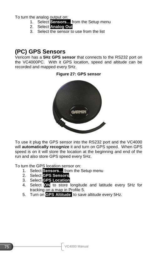
VC4000 Manual 75
To turn the analog output on: 1. Select Sensors… from the Setup menu 2. Select Analog Out 3. Select the sensor to use from the list
(PC) GPS Sensors
Vericom has a 5Hz GPS sensor that connects to the RS232 port on the VC4000PC. With it GPS location, speed and altitude can be recorded and mapped every 5Hz.
Figure 27: GPS sensor
To use it plug the GPS sensor into the RS232 port and the VC4000 will automatically recognize it and turn on GPS speed. When GPS speed is on it will store the location at the beginning and end of the run and also store GPS speed every 5Hz. To turn the GPS location sensor on:
1. Select Sensors… from the Setup menu 2. Select GPS Sensors 3. Select GPS Location 4. Select ON to store longitude and latitude every 5Hz for
tracking on a map in Profile 5. 5. Turn on GPS Altitude to save altitude every 5Hz.
VC4000 Manual 76
VC
40
00 S
etu
p
The internal accelerometers have several settings.
G Summation Use X, XY or XYZ axes for acceleration
G smoothing Smooth acceleration data
Zeroing On/Off Zero the accelerometers before a test
Accel Range (PC) Choose 2G or 6G maximum acceleration
G adjust Finely tune the pitch and roll factors
Graph Range Set the range for the on screen graphs
Alarm Threshold Set the accelerometer alarm for monitor G mode
Sample Rate (PC) Choose 1, 10, 100, 500 or 1000Hz
G Summation
Summation OFF o VC4000 mounted flat and level testing
direction in line with the X axis o Uses X axis only for calculations
Summation 2D (XY)
o VC4000 mounted flat and level o Uses the summation of X and Y vectors
for G and calculations o “G” is the summation of X Y vectors o “Gz” is the vertical axis
Summation 3D (XYZ)
o VC4000 mounted at any angle o Uses the summation of X Y and Z vectors
for calculations o “G” is the summation of X Y Z vectors
Accelerometer Setup
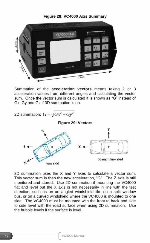
VC4000 Manual 77
Figure 28: VC4000 Axis Summary
Summation of the acceleration vectors means taking 2 or 3 acceleration values from different angles and calculating the vector sum. Once the vector sum is calculated it is shown as “G” instead of Gx, Gy and Gz if 3D summation is on.
2D summation: 22 GyGxG
Figure 29: Vectors
2D summation uses the X and Y axes to calculate a vector sum. This vector sum is then the new acceleration, “G”. The Z axis is still monitored and stored. Use 2D summation if mounting the VC4000 flat and level but the X axis is not necessarily in line with the test direction, such as on an angled windshield like on a split window bus, or on a curved windshield where the VC4000 is mounted to one side. The VC4000 must be mounted with the front to back and side to side level with the road surface when using 2D summation. Use the bubble levels if the surface is level.
VC4000 Manual 78
VC
40
00 S
etu
p
3D summation: 222 GzGyGxG
3D summation uses all 3 axes to calculate a vector sum. This vector sum is then the new acceleration, “G”. Use 3D summation when mounting the VC4000 at an angle to the road surface, such as with the display tilted up or down. NOTE ON 3D SUMMATION Since the Z axis accelerometer is included in the calculations when 3D summation is on the VC4000’s Z axis accelerometer is sensitive to road vibration. This vibration may trigger the VC4000 early if a vertical bump is run over in the road before the test starts. Also, if the surface is bumpy during the test, the accuracy of the acceleration may be degraded. On rough or bumpy surfaces the best accuracy may be achieved when mounting the VC4000 using 2 suction cups flat and level and using G summation OFF or 2D (XY). On a relatively smooth surface 3D summation accuracy will not be degraded. To change the G Summation:
1. Select Accelerometer… from the Setup menu 2. Select G Summation 3. Select OFF, 2D or 3D from the list
Default is 3D (XYZ).
G Smoothing
Smoothing is used to eliminate some of the vibration associated with vehicle testing. Smooth factors from 0 to 9 may be entered for each axis. The G data sent to Profile is the raw data before smoothing and Profile uses the VC4000’s smooth factor by default, but can be changed for more or less smoothing effect. See Profile help or the Profile manual to change G smoothing factors in Profile. If G Summation 2D or 3D is turned on Gx smoothing is used for the summation of the vectors smoothing. Default is smooth factor of 3 for each axis.
VC4000 Manual 79
To set the G Smoothing: 1. Select Accelerometer… from the Setup menu 2. Select G Smoothing 3. Type in a smooth factor from 0 – 9 for each axis, or
CLEAR / NO to keep the current number 4. Press ENTER / YES.
Zeroing On/Off
The VC4000’s accelerometers are set to a zero G reference at the factory on a calibrated level bench. When zeroing is turned off the VC4000 will use the zero G reference instead of zeroing before a test. It should be turned off only in isolated cases, such as when zeroing before a test is not possible. Default is on. To set the Zeroing On or Off:
1. Select Accelerometer… from the Setup menu 2. Select Zeroing On/Off 3. Select Zeroing OFF or Zeroing ON
(PC) Accel Range
The accelerometer in the VC4000PC has 2 ranges; 2G and 6G. Use 2G for braking or acceleration testing to use the most resolution possible. Use 6G for light impact testing. Speed and distance calculations may not be as accurate if using the 6G range. The range is for all 3 axes. To set the Accelerometer Range:
1. Select Accelerometer… from the Setup menu 2. Select Accel Range 3. Select 2G or 6G
Default range is 2G.
G Adjust
Use this to finely adjust the Pitch and Roll factors. The VC4000 is affected slightly by the tilt of the car caused by suspension shifts under acceleration or deceleration. This effect is slight and for the purposes of the VC4000 is considered to be similar for all vehicles designed to be driven on the highways including motorcycles, passenger cars, semi-tractor trailers and most off road vehicles. The
VC4000 Manual 80
VC
40
00 S
etu
p
VC4000 is set at a common pitch and roll factor (factor 1) for all vehicles with useful suspension systems. The VC4000 is shipped with “Pitch factor” and “Roll factor” of 1, which is an adjustment of 0.9700 for X and Y axis and a factor of 0 which is an adjustment of 1.000 for the Z axis. The pitch of the vehicle can be measured using the VC4000’s rate gyro. See Pitch/Roll Factors on page 67 for details. To set the G Adjust:
1. Select Accelerometer… from the Setup menu 2. Select G Adjust 3. Type in a number from 0.500 to 1.000 for each axis. 4. Press ENTER / YES.
Default adjustment is 0.9700.
Graph Range
Set the maximum range of the VC4000 acceleration bar graphs and friction circle graph when monitoring acceleration. To set the Graph Range:
1. Select Accelerometer… from the setup menu 2. Select Graph Range 3. Type in a number from 0.1 to 6.0. 4. Press ENTER / YES.
Default graph range is 1.0.
Alarm Threshold
There are 3 acceleration alarms that can be set so the VC4000 beeps when the acceleration threshold is exceeded; Accelerating, Braking and cornering. The alarm is turned off when it is set to 0.0. To set the Alarm Threshold:
1. Select Accelerometer… from the Setup menu 2. Select Alarm Threshold 3. Type in a number from 0.000 to 6.000. 4. Press ENTER / YES.
Default alarm threshold is turned off, 0.0.
VC4000 Manual 81
(PC) Sample Rate
Sample rate is how often the computer samples all the sensors. 100Hz means it samples 100 times per second, or once every 0.01 seconds. The VC4000PC can be set to sample at 1, 10, 100, 500 or 1000Hz for acceleration and monitor mode. Brake mode is always 100Hz regardless of the sample rate setting. If 500Hz is chosen the number of extra sensors that can be turned on is 13. If 1000Hz is chosen the number of extra sensors that can be turned on is 5. Regardless of the sample rate, GPS will only sample every 5Hz and OBDII is limited depending on the vehicle. VC4000 Brake Meter is always 100Hz. To set the Sample Rate:
1. Select Accelerometer… from the Setup menu 2. Select Sample Rate 3. Select 1, 10, 100, 500 or 1000
Default Rate is 100.
These settings generally are for acceleration testing.
Vehicle Weight
The VC4000 defaults to 1000 pounds unless you have changed it. Profile reads the VC4000’s weight when uploading to a computer. Vehicle weight is used in horsepower and torque calculations only. If you do not change the weight, horsepower and torque will be per 1000 pounds. Simply multiply HP/1000 by vehicle weight (including cargo) to get actual rear wheel HP and torque. To set the Vehicle Weight:
1. Select Performance… from the Setup menu 2. Select Vehicle Weight 3. Type in a number from 1 to 9999. 4. Press ENTER / YES.
Default weight is 1000.
Performance Setup
VC4000 Manual 82
VC
40
00 S
etu
p
Countdown On/Off
Turn countdown on to start the brake or acceleration run with a
countdown sequence. When the Auto Start key is pressed the
VC4000 will delay momentarily, then start the countdown. Acceleration runs use 3333, 2222, 1111 to simulate a drag strip tree with 0.50 sec. between each number and records reaction time. Brake runs use 5555, 4444, 3333, 2222, 1111 with 0.50 sec. between each number. In Acceleration mode the reaction timer starts when 1111 is displayed and the run timer starts when the rollout distance is reached. In Braking mode the run starts when the countdown is completed and the display shows “B R A K I N G”. Default countdown On/Off is Off.
Basic maintenance and information.
Unit Information
Displays the VC4000 model, Firmware version number, the date the firmware was released and when the VC4000 was last calibrated.
Run Tests
Tests some of the VC4000 hardware. Tests flash memory, accelerometer, real time clock and RS232 ports. WARNING: This test will erase all run data stored in memory.
Discharge Battery
Allows the battery to discharge quicker by leaving the backlighting on, and discharges more completely by not shutting off when a low battery condition happens.
Factory Maintenance Factory only settings.
Maintenance
VC4000 Manual 83
8. SENSOR INPUT
This section explains the hardware associated with each sensor input. Sensor inputs list
OBDII sensors (PC) o 27 EPA mandated sensors on USA
spec vehicles o Connect using VSI interface
1 Analog output port o Output various sensors (see list) o Connect to other data acquisition
systems
GPS Sensors (PC) o Store position at beginning and end of
test o Store GPS speed every 5Hz
External Activation o Only activates the start of the test o 5 – 36VDC
To calculate the total storage time when extra sensors are used, use
the formula: ratesamplesensorsof )3(#
2096400
Example: 100Hz sample rate, 3 extra sensors turned on:
seconds3494600
2096400
100)33(
2096400
When using GPS sensors, speed counts as 1 sensor, location counts as 4 sensors, and altitude counts as 1 sensor. Since there is only one RS232 port on the VC4000PC either the GPS or VSI can be connected, not both at the same time. If you require both you can have your VC4000PC upgraded to a VC4000DAQ which has 3 RS232 ports.
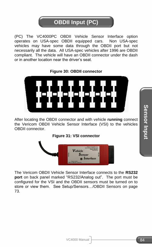
Se
ns
or In
pu
t
VC4000 Manual 84
(PC) The VC4000PC OBDII Vehicle Sensor Interface option operates on USA-spec OBDII equipped cars. Non USA-spec vehicles may have some data through the OBDII port but not necessarily all the data. All USA-spec vehicles after 1996 are OBDII compliant. The vehicle will have an OBDII connector under the dash or in another location near the driver’s seat.
Figure 30: OBDII connector
After locating the OBDII connector and with vehicle running connect the Vericom OBDII Vehicle Sensor Interface (VSI) to the vehicles OBDII connector.
Figure 31: VSI connector
The Vericom OBDII Vehicle Sensor Interface connects to the RS232 port on back panel marked “RS232/Analog out”. The port must be configured for the VSI and the OBDII sensors must be turned on to store or view them. See Setup/Sensors…/OBDII Sensors on page 73.
OBDII Input (PC)
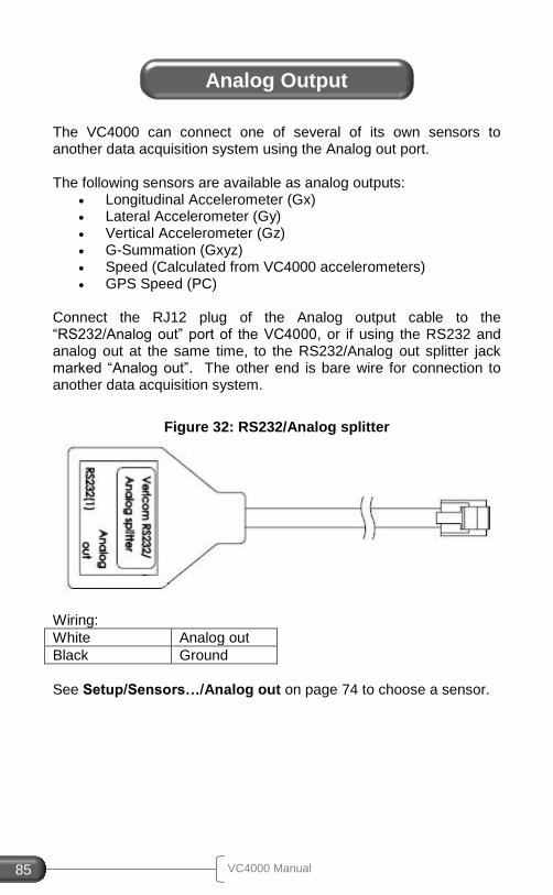
VC4000 Manual 85
The VC4000 can connect one of several of its own sensors to another data acquisition system using the Analog out port. The following sensors are available as analog outputs:
Longitudinal Accelerometer (Gx) Lateral Accelerometer (Gy) Vertical Accelerometer (Gz) G-Summation (Gxyz) Speed (Calculated from VC4000 accelerometers) GPS Speed (PC)
Connect the RJ12 plug of the Analog output cable to the “RS232/Analog out” port of the VC4000, or if using the RS232 and analog out at the same time, to the RS232/Analog out splitter jack marked “Analog out”. The other end is bare wire for connection to another data acquisition system.
Figure 32: RS232/Analog splitter
Wiring:
White Analog out
Black Ground
See Setup/Sensors…/Analog out on page 74 to choose a sensor.
Analog Output
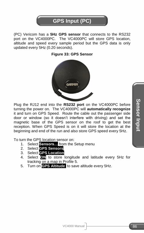
Se
ns
or In
pu
t
VC4000 Manual 86
(PC) Vericom has a 5Hz GPS sensor that connects to the RS232 port on the VC4000PC. The VC4000PC will store GPS location, altitude and speed every sample period but the GPS data is only updated every 5Hz (0.20 seconds).
Figure 33: GPS Sensor
Plug the RJ12 end into the RS232 port on the VC4000PC before turning the power on. The VC4000PC will automatically recognize it and turn on GPS Speed. Route the cable out the passenger side door or window (so it doesn’t interfere with driving) and set the magnetic base of the GPS sensor on the roof to get the best reception. When GPS Speed is on it will store the location at the beginning and end of the run and also store GPS speed every 5Hz. To turn the GPS location sensor on:
1. Select Sensors… from the Setup menu 2. Select GPS Sensors 3. Select GPS Location 4. Select ON to store longitude and latitude every 5Hz for
tracking on a map in Profile 5. 5. Turn on GPS Altitude to save altitude every 5Hz.
GPS Input (PC)

VC4000 Manual 87
Figure 34: Brake pedal activation switch
The External Activation Input is used for starting the run when one of the Reaction timers is used, when 12V is applied, or other input switch is used. This switch allows the operator to bypass the Auto Start G-Threshold. When using the external activation switch the activation of the test will be either the switch or the G-Threshold (0.2G default) whichever comes first. This switch may be used in the Acceleration mode as well as the Braking mode. When using the reaction timer switch the run will start the instant a key is pressed and a lamp turns on. When using the brake light switch or brake pedal switch the brake run will start the instant the brake lights come on or the pedal is touched, which is typically before the 0.2G threshold is reached. Drag Factor (Average G) will be significantly less when using the external activation switch because of the increase in time due to the braking systems mechanical reaction time. The activation switch may be connected to any 5 – 36VDC input.
Figure 35: External Activation Switch input
To install the external activation input use an External Activation cable available from Vericom Computers, Inc. Or make your own
External Activation
Plug reaction timer or other 12VDC activation source here
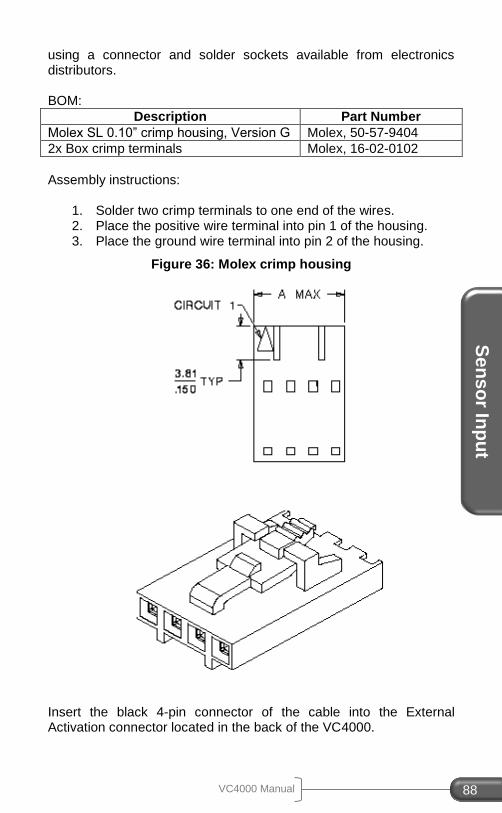
Se
ns
or In
pu
t
VC4000 Manual 88
using a connector and solder sockets available from electronics distributors. BOM:
Description Part Number
Molex SL 0.10” crimp housing, Version G Molex, 50-57-9404
2x Box crimp terminals Molex, 16-02-0102
Assembly instructions:
1. Solder two crimp terminals to one end of the wires. 2. Place the positive wire terminal into pin 1 of the housing. 3. Place the ground wire terminal into pin 2 of the housing.
Figure 36: Molex crimp housing
Insert the black 4-pin connector of the cable into the External Activation connector located in the back of the VC4000.
VC4000 Manual 89
To perform a braking test using the external activation switch:
1. From the READY screen press Braking (VC4000 will zero
adjust itself).
2. Press Auto Start . The VC4000 will display 'Auto Start
ready'. 3. Accelerate the vehicle to the desired initial braking speed. 4. After reaching the desired initial braking speed, brake as
efficiently as possible until the vehicle comes to a complete stop.
5. If using a reaction timer switch, press the switch prior to hitting the brakes.
E/T will be the time from when the switch was activated to when the vehicle came to a complete stop. Reaction time is the time from when activated to the G-Force threshold. Speed will be the speed when the switch was activated. Distance will be the distance from where the switch was activated to where the vehicle came to a complete stop. Reaction distance is the distance traveled during the reaction time.
To avoid false triggering of your braking run, you may press Auto-
Start at any time after zero adjusting. If connected to the brake
lights your foot may be on the brake pedal when the Auto Start key
is pressed but the next time the brake lights come on the unit will activate. You may need to set the G-Threshold high enough so it doesn’t activate before the external trigger. If the G-Threshold is not reached during the test, the VC4000 will run for a minimum of 10.00 seconds, so set the threshold to a value that will be reached during the test. See G-Threshold in Setup on page 65. You can test the operation of the switch before doing a run by pressing the
Braking key, let it zero adjust, press the Auto Start key, then press
the brake pedal. The VC4000 should run for 10.00 seconds then shut off.
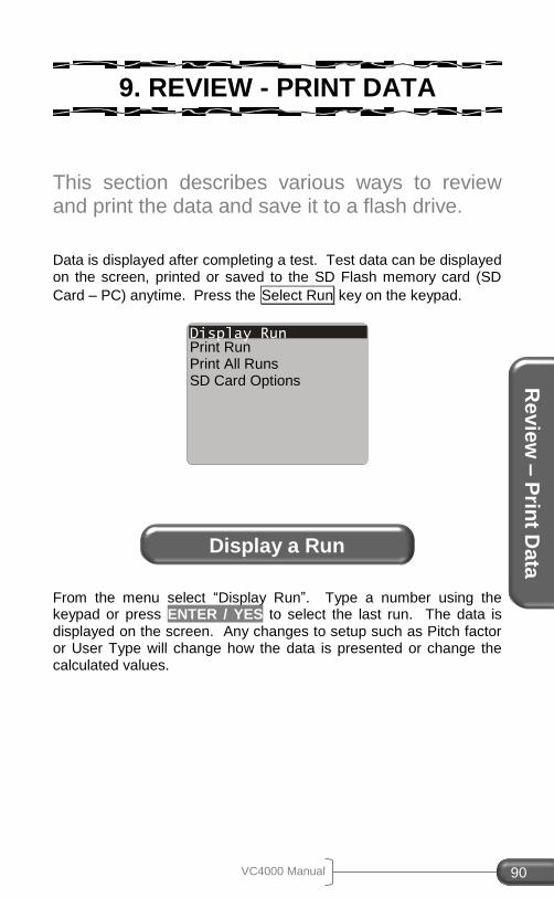
Re
vie
w –
Prin
t Da
ta
VC4000 Manual 90
9. REVIEW - PRINT DATA
This section describes various ways to review and print the data and save it to a flash drive. Data is displayed after completing a test. Test data can be displayed on the screen, printed or saved to the SD Flash memory card (SD
Card – PC) anytime. Press the Select Run key on the keypad.
From the menu select “Display Run”. Type a number using the keypad or press ENTER / YES to select the last run. The data is displayed on the screen. Any changes to setup such as Pitch factor or User Type will change how the data is presented or change the calculated values.
Display Run
Display a Run
Print Run Print All Runs SD Card Options
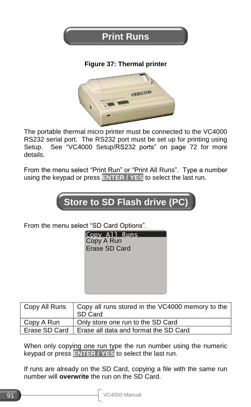
VC4000 Manual 91
Figure 37: Thermal printer
The portable thermal micro printer must be connected to the VC4000 RS232 serial port. The RS232 port must be set up for printing using Setup. See “VC4000 Setup/RS232 ports” on page 72 for more details. From the menu select “Print Run” or “Print All Runs”. Type a number using the keypad or press ENTER / YES to select the last run.
From the menu select “SD Card Options”.
Copy All Runs Copy all runs stored in the VC4000 memory to the SD Card
Copy A Run Only store one run to the SD Card
Erase SD Card Erase all data and format the SD Card
When only copying one run type the run number using the numeric keypad or press ENTER / YES to select the last run. If runs are already on the SD Card, copying a file with the same run number will overwrite the run on the SD Card.
Print Runs
Store to SD Flash drive (PC)
Copy All Runs Copy A Run Erase SD Card
PC
Inte
rfac
e
VC4000 Manual 92
10. PC INTERFACE
This section explains the interface between the VC4000 and a computer. The VC4000 has two ways to connect to computer to update firmware and transfer the data to our "Profile
©"software.
RS232 port o RS232 port o 19.2Kbps baud rate o Can use wireless modem (7 mile range)
USB port o USB 1.1 compatible o 12Mbps baud rate o Requires Vericom drivers for Windows
(PC) The VC4000PC is designed for use with the PC compatible software "Profile
©". With Profile, Time, Longitudinal G, Lateral G,
Vertical G, Speed, Distance, Horsepower, RPM, Torque, Gear ratio, GPS and OBDII parameters can be analyzed and compared. Profile is a powerful program utilizing graphs and data tables to analyze every sample of data with the VC4000PC. Once a connection to the computer is established and the VC4000PC is turned on, no additional key presses on the VC4000PC are required. Profile controls communications. See Profile Software Manual for software description and USB driver installation. NOTE: Only VC4000PC models can transfer data to Profile. Brake meters can only use Profile’s VC4000 Setup utility, and can use the VC4000Reflash utility to update firmware. Only Profile can be used to transfer the data from the VC4000PC. Once the data is imported into Profile, it can be exported to ASCII and opened by Microsoft’s Excel spreadsheet program or other software that reads ASCII data.
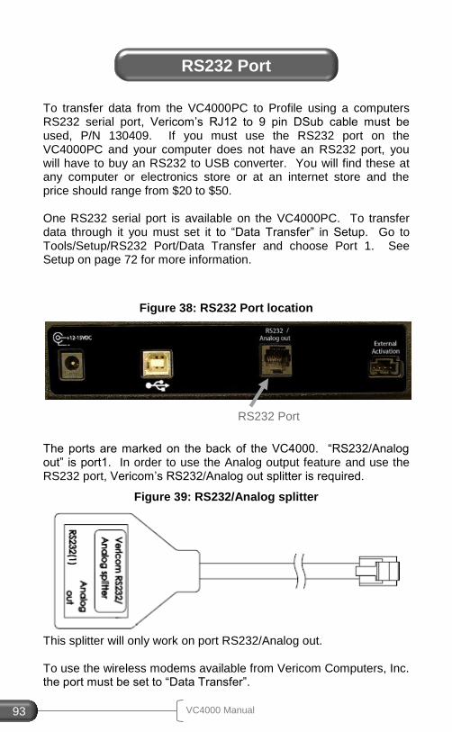
VC4000 Manual 93
To transfer data from the VC4000PC to Profile using a computers RS232 serial port, Vericom’s RJ12 to 9 pin DSub cable must be used, P/N 130409. If you must use the RS232 port on the VC4000PC and your computer does not have an RS232 port, you will have to buy an RS232 to USB converter. You will find these at any computer or electronics store or at an internet store and the price should range from $20 to $50. One RS232 serial port is available on the VC4000PC. To transfer data through it you must set it to “Data Transfer” in Setup. Go to Tools/Setup/RS232 Port/Data Transfer and choose Port 1. See Setup on page 72 for more information.
Figure 38: RS232 Port location
The ports are marked on the back of the VC4000. “RS232/Analog out” is port1. In order to use the Analog output feature and use the RS232 port, Vericom’s RS232/Analog out splitter is required.
Figure 39: RS232/Analog splitter
This splitter will only work on port RS232/Analog out. To use the wireless modems available from Vericom Computers, Inc. the port must be set to “Data Transfer”.
RS232 Port
RS232 Port
PC
Inte
rfac
e
VC4000 Manual 94
1. Plug the provided RS232 to PC cable into your computer
and into the VC4000 RS232 port. 2. In Profile click on the menu Tools/Options (or click the icon)
and set the COM port to “Auto” or specifically choose the COM port (usually port 1).
3. To import data click on the menu Import/Auto (or click the icon). To set or get VC4000 settings click menu Tools/VC4000 Setup (or click the icon).
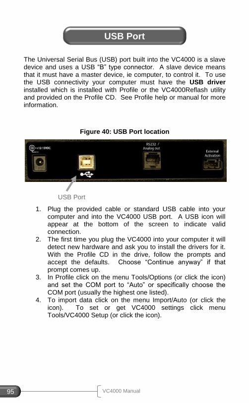
VC4000 Manual 95
The Universal Serial Bus (USB) port built into the VC4000 is a slave device and uses a USB “B” type connector. A slave device means that it must have a master device, ie computer, to control it. To use the USB connectivity your computer must have the USB driver installed which is installed with Profile or the VC4000Reflash utility and provided on the Profile CD. See Profile help or manual for more information.
Figure 40: USB Port location
1. Plug the provided cable or standard USB cable into your computer and into the VC4000 USB port. A USB icon will appear at the bottom of the screen to indicate valid connection.
2. The first time you plug the VC4000 into your computer it will detect new hardware and ask you to install the drivers for it. With the Profile CD in the drive, follow the prompts and accept the defaults. Choose “Continue anyway” if that prompt comes up.
3. In Profile click on the menu Tools/Options (or click the icon) and set the COM port to “Auto” or specifically choose the COM port (usually the highest one listed).
4. To import data click on the menu Import/Auto (or click the icon). To set or get VC4000 settings click menu Tools/VC4000 Setup (or click the icon).
USB Port
USB Port
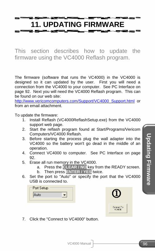
VC4000 Manual 96
Up
da
ting
Firm
wa
re
11. UPDATING FIRMWARE
This section describes how to update the firmware using the VC4000 Reflash program. The firmware (software that runs the VC4000) in the VC4000 is designed so it can updated by the user. First you will need a connection from the VC4000 to your computer. See PC Interface on page 92. Next you will need the VC4000 Reflash program. This can be found on our web site: http://www.vericomcomputers.com/Support/VC4000_Support.html or from an email attachment. To update the firmware:
1. Install Reflash (VC4000ReflashSetup.exe) from the VC4000 support web page.
2. Start the reflash program found at Start/Programs/Vericom Computers/VC4000 Reflash.
3. Before starting the process plug the wall adapter into the VC4000 so the battery won't go dead in the middle of an operation.
4. Connect VC4000 to computer. See PC Interface on page 92.
5. Erase all run memory in the VC4000. a. Press the CLEAR / NO key from the READY screen. b. Then press ENTER / YES twice.
6. Set the port to "Auto" or specify the port that the VC4000 USB is connected to.
7. Click the "Connect to VC4000" button.

VC4000 Manual 97
8. Click the Re-Flash button. 9. When downloading to memory is done the program will ask
you to power off the VC4000, then back on. When the VC4000 is turned back on it will transfer the firmware into the program area of flash memory.
10. Then it will ask you to hold the power button, after which it will delete the run file flash memory.
11. The reflash program may be exited after the is shown
and the VC4000 displays “Power off & on” 12. Reflashing firmware is complete.
If power is lost in the middle of the reflash process, the VC4000 will have to be sent back to the factory for reflashing.

VC4000 Manual 98
Ch
arg
ing
the
Ba
ttery
12. CHARGING THE BATTERY
This section describes how to properly charge the battery. The battery charger inside the VC4000 requires 12 to 16 Volts DC at 800 milli Amps or greater to operate, so most regulated 12V battery chargers will work. Suitable chargers are available from Vericom Computers, Inc. The center conductor of the VC4000 power adapter is positive, and the connector has a 5mm OD and a 2.1mm ID. The VC4000 will charge from a vehicle's cigarette lighter. It takes about three hours to fully charge them. The batteries take about six hours to fully discharge. The battery gauge on the display will show arrows indicating that the battery is charging. The green charging LED on the front of the unit will light while it is charging and go out when it is fully charged. The green LED will turn on anytime the unit is plugged in and stays on until the battery is fully charged. DO NOT use the charger from the VC4000 to charge or power the portable thermal printer. It is reverse polarity and WILL destroy the printer electronics. Similarly, do not power the VC4000 using the thermal printers wall adapter. The VC4000 has protection circuitry for voltages and currents exceeding the maximum rating for the internal components, as well as reverse polarity protection. But continuous over voltages or reverse voltages may eventually cause damage to the input circuitry.
VC4000 Manual 99
13. CUSTOMER SERVICE
This section describes Vericom’s warranty, repair and Accessories.
The manufacturer warrants that the VC4000 computer will be free from defects in material or workmanship appearing under normal use and service. This warranty extends only to the original purchaser and does not apply if the product has been connected, installed or adjusted other than in accordance with the instructions furnished by the Manufacturer. The manufacturer will repair or replace any parts that are defective in workmanship or materials for a period of one year from the date of purchase. The manufacturer does not warranty the installation of the VC4000 computer and therefore will not be responsible for damage caused by installation. This warranty covers only the VC4000 computer and is not extended to equipment or component parts used in conjunction with the VC4000 computer. The manufacturer will not be liable for incidental and consequential damages or the loss of use of your vehicle. This warranty gives you specific legal rights and you also may have rights that vary from state to state.
Repairs not covered by warranty are available by returning the unit, prepaid postage, to the manufacturer. Repair charges and shipping will be billed to the customer prior to repairing or returning the unit to the customer.
Warranty
Repairs
VC4000 Manual 100
Cu
sto
me
r Serv
ice
Please include the following information when returning a VC4000:
1. Your name 2. Company name 3. Shipping address 4. Daytime telephone number 5. Model and Serial number of unit being returned 6. Description of problem 7. Method of payment 8. Description of any upgrades or repairs since
purchased For service, repair or product information contact: Vericom Computers, Inc. 14320 James Rd Suite 200 Rogers, MN 55374 763-428-1381 Fax 763-428-4856 [email protected] www.vericomcomputers.com
VC4000PC VC4000DAQ OBDII Monitoring 5Hz GPS position, altitude and speed Portable micro thermal printer 12V activation cable Brake pedal activation switch Brake Reaction Timer hardware (software is included standard) RS232/Analog out splitter Analog output cable Dual vacuum cup mounting kit Analog sensor input – See price sheet on web site for list Junction box for 6 sensors into 1 modular connector Wireless data transmission for up to 7 miles
Options, Upgrades
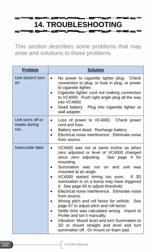
VC4000 Manual 101
14. TROUBLESHOOTING
This section describes some problems that may arise and solutions to those problems.
Problem Solution
Unit doesn't turn on
No power to cigarette lighter plug. Check connection to plug, or fuse in plug, or power to cigarette lighter.
Cigarette lighter cord not making connection to VC4000. Push right angle plug all the way into VC4000.
Dead battery. Plug into cigarette lighter or wall adapter.
Unit turns off or resets during run.
Loss of power to VC4000. Check power cord and fuse.
Battery went dead. Recharge battery.
Electrical noise interference. Eliminate noise from source.
Inaccurate data VC4000 was not at same incline as when zero adjusted or level of VC4000 changed since zero adjusting. See page 4 for mounting.
Summation was not on and unit was mounted at an angle.
VC4000 started timing too soon. If 3D summation is on a bump may have triggered it. See page 65 to adjust threshold.
Electrical noise interference. Eliminate noise from source.
Wrong pitch and roll factor for vehicle. See page 67 to adjust pitch and roll factor.
Settle time was calculated wrong. Import to Profile and set it manually.
Vibration: Mount level and turn Summation to 2D or mount straight and level and turn summation off. Or mount on foam pad.
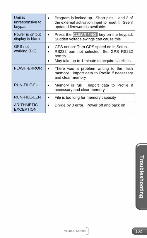
VC4000 Manual 102
Tro
ub
les
ho
otin
g
Unit is unresponsive to keypad
Program is locked up. Short pins 1 and 2 of the external activation input to reset it. See if updated firmware is available.
Power is on but display is blank
Press the CLEAR / NO key on the keypad. Sudden voltage swings can cause this.
GPS not working (PC)
GPS not on: Turn GPS speed on in Setup.
RS232 port not selected: Set GPS RS232 port to 1.
May take up to 1 minute to acquire satellites.
FLASH-ERROR There was a problem writing to the flash memory. Import data to Profile if necessary and clear memory
RUN-FILE-FULL Memory is full. Import data to Profile if necessary and clear memory
RUN-FILE-LEN File is too long for memory capacity
ARITHMETIC EXCEPTION
Divide by 0 error. Power off and back on
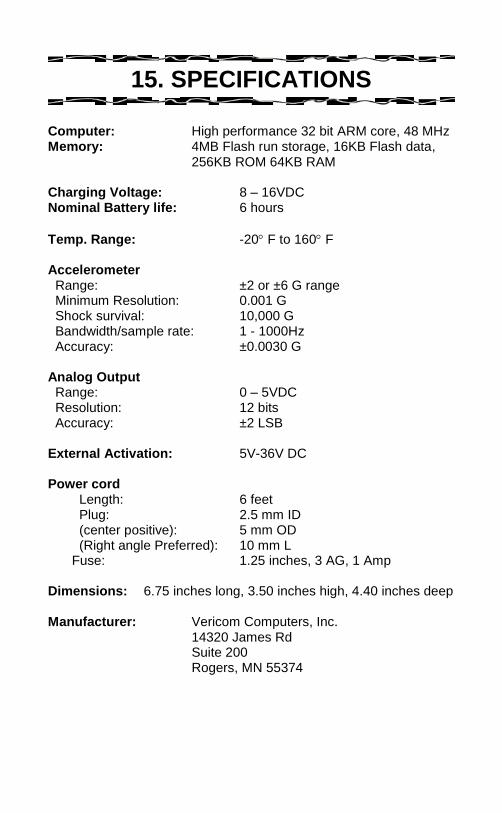
15. SPECIFICATIONS
Computer: High performance 32 bit ARM core, 48 MHz Memory: 4MB Flash run storage, 16KB Flash data,
256KB ROM 64KB RAM Charging Voltage: 8 – 16VDC Nominal Battery life: 6 hours
Temp. Range: -20 F to 160 F Accelerometer Range: ±2 or ±6 G range Minimum Resolution: 0.001 G Shock survival: 10,000 G Bandwidth/sample rate: 1 - 1000Hz Accuracy: ±0.0030 G Analog Output Range: 0 – 5VDC Resolution: 12 bits Accuracy: ±2 LSB External Activation: 5V-36V DC Power cord Length: 6 feet Plug: 2.5 mm ID (center positive): 5 mm OD (Right angle Preferred): 10 mm L Fuse: 1.25 inches, 3 AG, 1 Amp Dimensions: 6.75 inches long, 3.50 inches high, 4.40 inches deep Manufacturer: Vericom Computers, Inc. 14320 James Rd Suite 200 Rogers, MN 55374
Sp
ec
ifica
tion
s
VC4000 Manual 104
This page intentionally left blank