Embed Size (px)
Citation preview
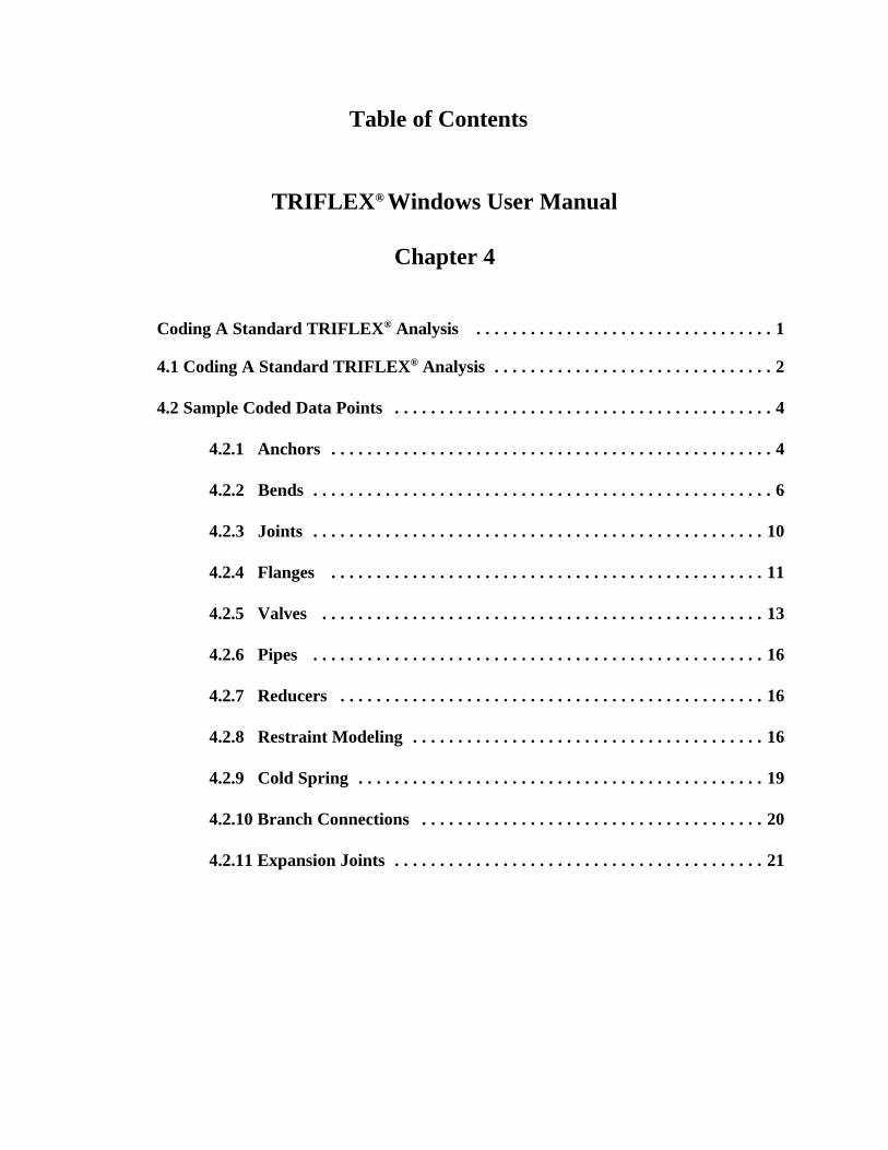
Table of Contents
TRIFLEX® Windows User Manual
Chapter 4
Coding A Standard TRIFLEX® Analysis . . . . . . . . . . . . . . . . . . . . . . . . . . . . . . . . . 1
4.1 Coding A Standard TRIFLEX® Analysis . . . . . . . . . . . . . . . . . . . . . . . . . . . . . . . 2
4.2 Sample Coded Data Points . . . . . . . . . . . . . . . . . . . . . . . . . . . . . . . . . . . . . . . . . . 4
4.2.1 Anchors . . . . . . . . . . . . . . . . . . . . . . . . . . . . . . . . . . . . . . . . . . . . . . . . . 4
4.2.2 Bends . . . . . . . . . . . . . . . . . . . . . . . . . . . . . . . . . . . . . . . . . . . . . . . . . . . 6
4.2.3 Joints . . . . . . . . . . . . . . . . . . . . . . . . . . . . . . . . . . . . . . . . . . . . . . . . . . 10
4.2.4 Flanges . . . . . . . . . . . . . . . . . . . . . . . . . . . . . . . . . . . . . . . . . . . . . . . . 11
4.2.5 Valves . . . . . . . . . . . . . . . . . . . . . . . . . . . . . . . . . . . . . . . . . . . . . . . . . 13
4.2.6 Pipes . . . . . . . . . . . . . . . . . . . . . . . . . . . . . . . . . . . . . . . . . . . . . . . . . . 16
4.2.7 Reducers . . . . . . . . . . . . . . . . . . . . . . . . . . . . . . . . . . . . . . . . . . . . . . . 16
4.2.8 Restraint Modeling . . . . . . . . . . . . . . . . . . . . . . . . . . . . . . . . . . . . . . . 16
4.2.9 Cold Spring . . . . . . . . . . . . . . . . . . . . . . . . . . . . . . . . . . . . . . . . . . . . . 19
4.2.10 Branch Connections . . . . . . . . . . . . . . . . . . . . . . . . . . . . . . . . . . . . . . 20
4.2.11 Expansion Joints . . . . . . . . . . . . . . . . . . . . . . . . . . . . . . . . . . . . . . . . . 21
2
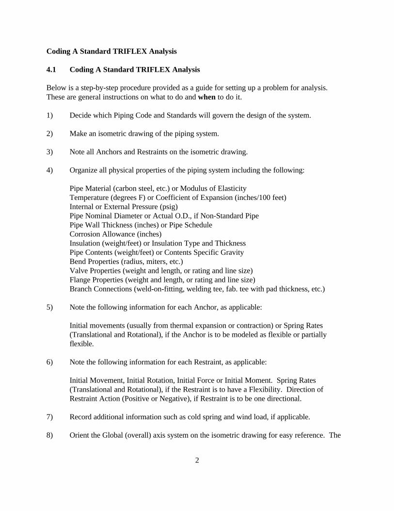
Coding A Standard TRIFLEX Analysis
4.1 Coding A Standard TRIFLEX Analysis
Below is a step-by-step procedure provided as a guide for setting up a problem for analysis. These are general instructions on what to do and when to do it.
1) Decide which Piping Code and Standards will govern the design of the system.
2) Make an isometric drawing of the piping system.
3) Note all Anchors and Restraints on the isometric drawing.
4) Organize all physical properties of the piping system including the following:
Pipe Material (carbon steel, etc.) or Modulus of ElasticityTemperature (degrees F) or Coefficient of Expansion (inches/100 feet)Internal or External Pressure (psig)Pipe Nominal Diameter or Actual O.D., if Non-Standard PipePipe Wall Thickness (inches) or Pipe ScheduleCorrosion Allowance (inches)Insulation (weight/feet) or Insulation Type and ThicknessPipe Contents (weight/feet) or Contents Specific GravityBend Properties (radius, miters, etc.)Valve Properties (weight and length, or rating and line size)Flange Properties (weight and length, or rating and line size)Branch Connections (weld-on-fitting, welding tee, fab. tee with pad thickness, etc.)
5) Note the following information for each Anchor, as applicable:
Initial movements (usually from thermal expansion or contraction) or Spring Rates(Translational and Rotational), if the Anchor is to be modeled as flexible or partiallyflexible.
6) Note the following information for each Restraint, as applicable:
Initial Movement, Initial Rotation, Initial Force or Initial Moment. Spring Rates(Translational and Rotational), if the Restraint is to have a Flexibility. Direction ofRestraint Action (Positive or Negative), if Restraint is to be one directional.
7) Record additional information such as cold spring and wind load, if applicable.
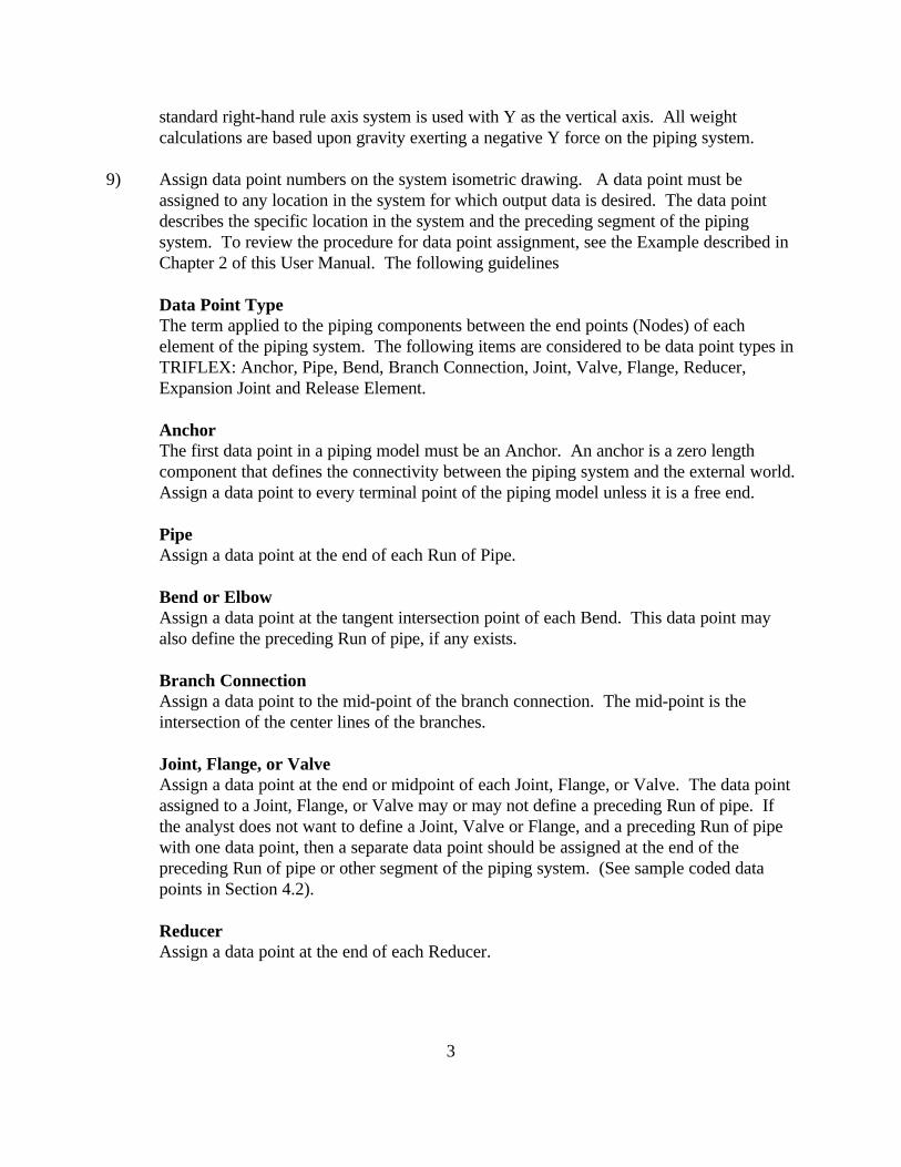
8) Orient the Global (overall) axis system on the isometric drawing for easy reference. The
3
standard right-hand rule axis system is used with Y as the vertical axis. All weightcalculations are based upon gravity exerting a negative Y force on the piping system.
9) Assign data point numbers on the system isometric drawing. A data point must beassigned to any location in the system for which output data is desired. The data pointdescribes the specific location in the system and the preceding segment of the pipingsystem. To review the procedure for data point assignment, see the Example described inChapter 2 of this User Manual. The following guidelines
Data Point TypeThe term applied to the piping components between the end points (Nodes) of eachelement of the piping system. The following items are considered to be data point types inTRIFLEX: Anchor, Pipe, Bend, Branch Connection, Joint, Valve, Flange, Reducer,Expansion Joint and Release Element.
AnchorThe first data point in a piping model must be an Anchor. An anchor is a zero lengthcomponent that defines the connectivity between the piping system and the external world. Assign a data point to every terminal point of the piping model unless it is a free end.
PipeAssign a data point at the end of each Run of Pipe.
Bend or ElbowAssign a data point at the tangent intersection point of each Bend. This data point mayalso define the preceding Run of pipe, if any exists.
Branch ConnectionAssign a data point to the mid-point of the branch connection. The mid-point is theintersection of the center lines of the branches.
Joint, Flange, or ValveAssign a data point at the end or midpoint of each Joint, Flange, or Valve. The data pointassigned to a Joint, Flange, or Valve may or may not define a preceding Run of pipe. Ifthe analyst does not want to define a Joint, Valve or Flange, and a preceding Run of pipewith one data point, then a separate data point should be assigned at the end of thepreceding Run of pipe or other segment of the piping system. (See sample coded datapoints in Section 4.2).
ReducerAssign a data point at the end of each Reducer.
4
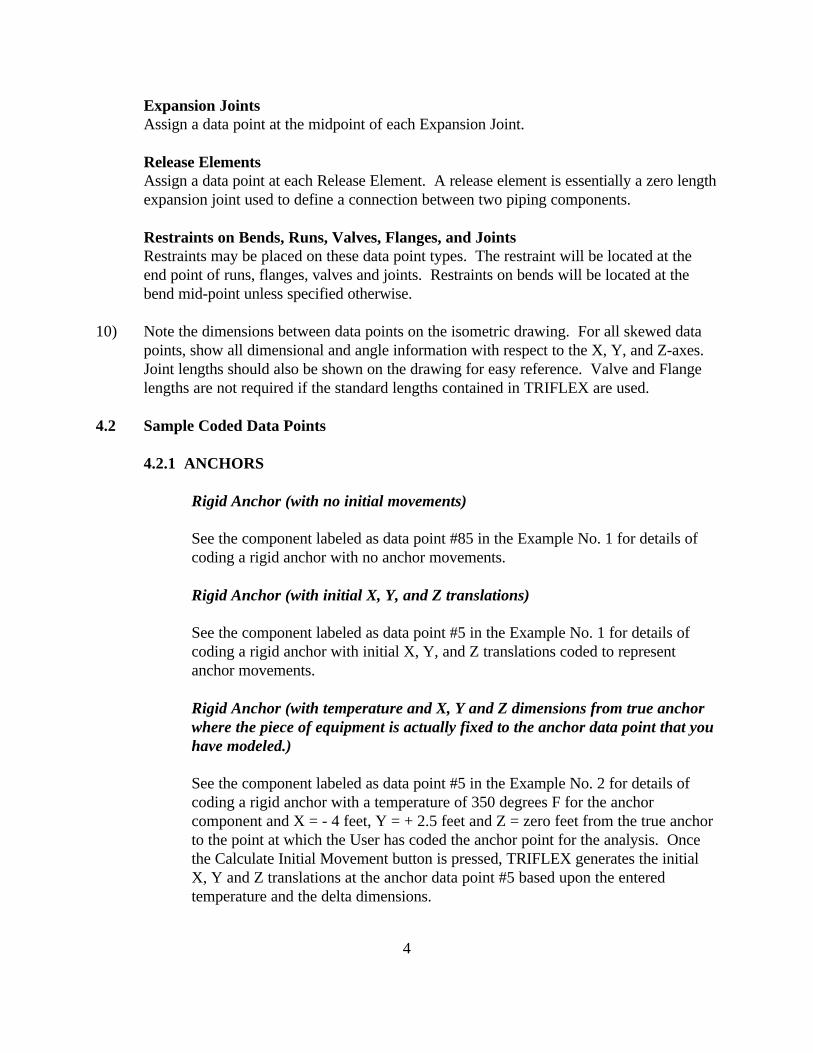
Expansion JointsAssign a data point at the midpoint of each Expansion Joint.
Release ElementsAssign a data point at each Release Element. A release element is essentially a zero lengthexpansion joint used to define a connection between two piping components.
Restraints on Bends, Runs, Valves, Flanges, and JointsRestraints may be placed on these data point types. The restraint will be located at theend point of runs, flanges, valves and joints. Restraints on bends will be located at thebend mid-point unless specified otherwise.
10) Note the dimensions between data points on the isometric drawing. For all skewed datapoints, show all dimensional and angle information with respect to the X, Y, and Z-axes. Joint lengths should also be shown on the drawing for easy reference. Valve and Flangelengths are not required if the standard lengths contained in TRIFLEX are used.
4.2 Sample Coded Data Points
4.2.1 ANCHORS
Rigid Anchor (with no initial movements)
See the component labeled as data point #85 in the Example No. 1 for details ofcoding a rigid anchor with no anchor movements.
Rigid Anchor (with initial X, Y, and Z translations)
See the component labeled as data point #5 in the Example No. 1 for details ofcoding a rigid anchor with initial X, Y, and Z translations coded to representanchor movements.
Rigid Anchor (with temperature and X, Y and Z dimensions from true anchorwhere the piece of equipment is actually fixed to the anchor data point that youhave modeled.)
See the component labeled as data point #5 in the Example No. 2 for details ofcoding a rigid anchor with a temperature of 350 degrees F for the anchorcomponent and X = - 4 feet, Y = + 2.5 feet and Z = zero feet from the true anchorto the point at which the User has coded the anchor point for the analysis. Oncethe Calculate Initial Movement button is pressed, TRIFLEX generates the initialX, Y and Z translations at the anchor data point #5 based upon the enteredtemperature and the delta dimensions.
5
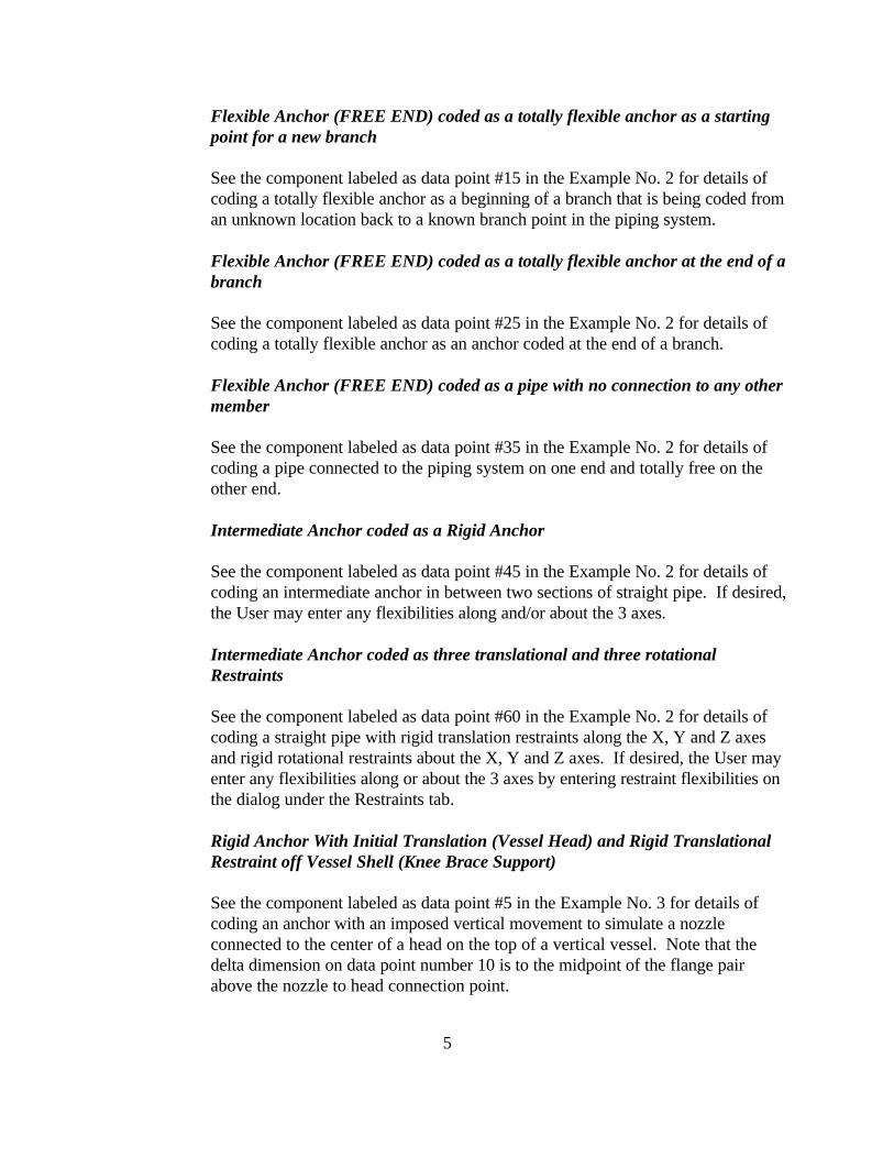
Flexible Anchor (FREE END) coded as a totally flexible anchor as a startingpoint for a new branch
See the component labeled as data point #15 in the Example No. 2 for details ofcoding a totally flexible anchor as a beginning of a branch that is being coded froman unknown location back to a known branch point in the piping system.
Flexible Anchor (FREE END) coded as a totally flexible anchor at the end of abranch
See the component labeled as data point #25 in the Example No. 2 for details ofcoding a totally flexible anchor as an anchor coded at the end of a branch.
Flexible Anchor (FREE END) coded as a pipe with no connection to any othermember
See the component labeled as data point #35 in the Example No. 2 for details ofcoding a pipe connected to the piping system on one end and totally free on theother end.
Intermediate Anchor coded as a Rigid Anchor
See the component labeled as data point #45 in the Example No. 2 for details ofcoding an intermediate anchor in between two sections of straight pipe. If desired,the User may enter any flexibilities along and/or about the 3 axes.
Intermediate Anchor coded as three translational and three rotationalRestraints
See the component labeled as data point #60 in the Example No. 2 for details ofcoding a straight pipe with rigid translation restraints along the X, Y and Z axesand rigid rotational restraints about the X, Y and Z axes. If desired, the User mayenter any flexibilities along or about the 3 axes by entering restraint flexibilities onthe dialog under the Restraints tab.
Rigid Anchor With Initial Translation (Vessel Head) and Rigid Translational Restraint off Vessel Shell (Knee Brace Support)
See the component labeled as data point #5 in the Example No. 3 for details ofcoding an anchor with an imposed vertical movement to simulate a nozzleconnected to the center of a head on the top of a vertical vessel. Note that thedelta dimension on data point number 10 is to the midpoint of the flange pairabove the nozzle to head connection point.
6
See the component labeled as data point #25 in the Example No. 3 for details ofcoding a rigid +Y restraint that moves upward with the vessel shell as it grows butpermits the pipe to move up off the knee brace support if the pipe moved up morethan the vessel at that point. A limit stop is entered along the Y axis with a lowerlimit movement imposed and the upper limit specified as a much larger numberwhich will never restrict the pipe. Entering a limit stop requires a lower limit to beentered as well as an upper limit. Note that this knee brace only provides verticalsupport. It does not restrict movement in the lateral plane.
Capped End coded as a Free End
See the component labeled as data point #35 in the Example No. 2 for details ofcoding a pipe connected to the piping system on one end and totally free on theother end.
Flanged Free End coded as a pair of flanges with no connection to any otherpiping component beyond the flange pair
See the components labeled as data point #70 & 75 in the Example No. 2 fordetails of coding a pipe connected to the piping system on one end and followed bya weld neck flange (data point #70) and then followed by a blind flange (data point#75).
4.2.2. BENDS
Standard Long Radius Elbow
See the component labeled as data point #40 in the Example No. 2 for details ofcoding a standard long radius bend.
Standard Short Radius Elbow
See the component labeled as data point #55 in the Example No. 2 for details ofcoding a standard short radius bend.
Elbow with User Defined Radius
See the component labeled as data point #80 in the Example No. 2 for details ofcoding an elbow with a non-standard bend radius. In the example, we have codeda 4 D elbow and because it is defined as an elbow, the fitting thickness can beentered for only the bend arc.
7
Bend with User Defined Radius
See the component labeled as data point #85 in the Example No. 2 for details ofcoding an bend with a non-standard bend radius. In the example, we have coded a3 D bend.
Miter Bend (closely-spaced)
See the component labeled as data point #45 in the Example No. 1 for details ofcoding a closely spaced miter bend with four miter cuts and a bend radius ratio of2 and a flange pair immediately following the miter bend. The flange pairfollowing the bend has been defined by specifying the data point at the beginningof the flange pair.
Miter Bend (widely spaced)
See the component labeled as data point #30 in the Example No. 1 for details ofcoding a widely spaced miter bend with two miter cuts and a bend radius ratio of3.
Standard Long Radius Elbow with a Rigid One-Directional +Y Restraintlocated at the midpoint of the elbow
See the component labeled as data point #40 in the Example No. 1 for details ofcoding a long radius elbow with a rigid one-directional restraint acting in the +Ydirection resisting -Y movement. The restraint is attached at the midpoint of theelbow, not the tangent intersection point.
Elbow with an existing Spring Support attached to the Bend Mid-Point
See the component labeled as data point #40 in the Example No. 3 for details ofcoding a long radius elbow with an existing spring hanger attached at the midpointof the elbow, not the tangent intersection point. The spring hanger has a knowninstalled load and spring rate.
Elbow with One End Flanged and a Spring Support at Bend Mid-Point
See the components labeled as data points #10 and 15 in Example No.4 for detailsof coding a long radius bend with a single flange immediately preceding the bend. The flange is welded directly to the near end or leading end of the bend. Note ondata point #10, the minimum length for the single flange has been checked toindicate to TRIFLEX that the flange is being entered with no preceding segment of
8
pipe. To indicate to TRIFLEX that you are entering a single flange rather than aflange pair (default) on data point #10, the radio button for one flange shown inthe Flange data area of the dialog should be checked. TRIFLEX defaults to twoflanges. The default orientation of the single flange in TRIFLEX is facing forward. In this Example, a flange facing backwards is what is desired. Therefore, a checkis placed in the “Flange is facing backward” check box.
As for the elbow, it has been coded as a standard long radius elbow with a checkmark in the “Near End” check box in the Flange Ends area of the dialog. With thisbox checked, TRIFLEX will modify the flexibility characteristic for this elbowbased upon the criteria contained in the piping code selected. To indicate toTRIFLEX where you wish to have the spring hanger connected to the elbow, youmust place a check mark in one of the Near, Mid or Far check boxes in theRestraint Attachment Point on Bend Centerline area of the bend dialog. In thisexample, the Mid Point has been selected.
Standard Long Radius Bend (with a +Y translational restraint acting at theend point of the bend).
See the component labeled as data point #25 in the Example No. 4 for details ofcoding a long radius elbow with an restraint acting in the +Y direction attached atend point of the elbow, not the tangent intersection point. Therefore, a checkmark has been placed in Far check box in the Restraint Attachment Point on BendCenterline area of the bend dialog. In addition, a check mark has been placed inthe +Y restraint check box on the restraint dialog for this component.
Standard Long Radius Bend (with a -Z translational restraint acting at a pointthat is sixty [60] degrees from the beginning weld point of the bend).
See the component labeled as data point #30 in the Example No. 4 for details ofcoding a long radius elbow with an restraint acting in the -Z direction attached at apoint on the elbow that is sixty (60) degrees from the beginning weld point andthirty (30) degrees from the ending weld point. To indicate the angle ofattachment from the beginning of the bend, the check marks in the Near, Mid, Farcheck boxes should be removed and the angle in degrees should be entered in thefield provided placed in the Restraint Attachment Point on Bend Centerline area ofthe bend dialog. In addition, a check mark has been placed in the -Z restraintcheck box on the restraint dialog for this component.
Base Ell Support modeled from a Branch Point to a Rigid Anchor below anElbow
See the components labeled as data points #20, 25, 30, 35 and 40 in the Example
9
No. 8 for details of coding a Base Ell Support as long radius elbow with ansupport leg coded from a branch point just above the weld point to an anchor pointbelow the tangent intersection point of the elbow. In this example, the base ell legis rigidly anchored to the ground or structure below the elbow. Note that thetemperature, pressure, contents and insulation have been removed from thecomponent described by data point 40.
Base Ell Support modeled from a Branch Point to an Anchor below an Elbow -the Anchor is free in all directions except the Y axis
See the components labeled as data points #55, 60, 65, 70 and 75 in the ExampleNo. 8 for details of coding a Base Ell Support as long radius elbow with ansupport leg coded from a branch point just above the weld point to an anchor pointbelow the tangent intersection point of the elbow. In this example, the anchorlocated at the bottom of the base ell leg is free along the X and Z axes and aboutX, Y and Z and rigid along the Y axis. Note that the temperature, pressure,contents and insulation have been removed from the component described by datapoint 75. Note further that the branch connection must be outside of the elbowitself. The branch point can not be on the elbow between weld points. It can beon the weld point, if desired by the user.
Base Ell Support modeled from a Branch Point to a Free End below an Elbow -the free end has a +Y restraint acting on it to allow for lift off
See the components labeled as data points #90, 95, 100, 105, 110 and 115 in theExample No. 8 for details of coding a Base Ell Support as long radius elbow withan support leg coded from a branch point just above the weld point to a free endon the base ell leg below the tangent intersection point of the elbow. In thisexample, the branch from the equipment nozzle is coded back to the weld pointjust above the elbow and the free end at the bottom of the base ell leg has a +Yrestraint on it which allows for the pipe to lift off the structure without hold downrestraint. The direction of coding a branch from the equipment to the branch pointis opposite that traversed in the two examples just above. Note that thetemperature, pressure, contents and insulation have been removed from thecomponent described by data point 115. Note further that the branch connectionmust be outside of the elbow itself. The branch point can not be on the elbowbetween weld points. It can be on the weld point, if desired by the user.
Base Ell Support modeled from a Branch Point to a Free End below an Elbow -the free end has a +Y restraint acting on it to allow for lift off and africtional resistance
See the components labeled as data points #145, 150, 155, 160, 165 and 175 in the
10
Example No. 8 for details of coding a Base Ell Support as long radius elbow withan support leg coded from a branch point just above the weld point to a free endon the base ell leg below the tangent intersection point of the elbow. In thisexample, the branch from the equipment nozzle is coded back to the weld pointjust above the elbow and the free end at the bottom of the base ell leg has a +Yrestraint on it which allows for the pipe to lift off the structure without hold downrestraint. The direction of coding a branch from the equipment to the branch pointis opposite that traversed in the first two examples above. On the +Y restraint, afriction coefficient of 0.3 is specified to resist movement in the X-Z plane. Notethat the temperature, pressure, contents and insulation have been removed fromthe component described by data point 175. Note further that the branchconnection must be outside of the elbow itself. The branch point can not be on theelbow between weld points. It can be on the weld point, if desired by the user.
Dead or Dummy Leg coded as an extension of a line through a branchconnection
See the components labeled as data points #130, 135 and 170 in the Example No.8 for details of coding a dummy leg support as an extension of a branchconnection. Data point 135 is coded as a free end with a +Y restraint resisting -Ymovement. Note that the temperature, pressure, contents and insulation have beenremoved from the component described by data point 135. Note further that thebranch connection must be outside of the elbow itself. The branch point can notbe on the elbow between weld points. It can be on the weld point, if desired by theuser.
Dummy Leg coded as an extension of a line through an elbow
See the components labeled as data points #170, 180 and 190 in the Example No.8 for details of coding a dummy leg support as an extension of a line through anelbow. Data point 180 is coded as a free end with a +Y restraint resisting -Ymovement. Note that the temperature, pressure, contents and insulation have beenremoved from the component described by data point 190. Note that the branchconnection must be outside of the elbow itself. The branch point can not be on theelbow between weld points. It can be on the weld point, if desired by the user.
4.2.3 JOINTS
Rigid Joint with no preceding run of pipe
See the component labeled as data point #60 in Example No. 3 for details ofcoding a Rigid Joint with no preceding run of pipe. The objective of thiscomponent is to fill the distance between the previous data point to the defined
11
data point with a totally rigid member that weighs 35 pounds as entered by theUser. Note that the length specified by the delta dimensions must be equal to thelength specified by the User in the Rigid Joint Properties area of the dialog. If thedelta dimension is longer than the joint length, the difference will be considered asa preceding run of pipe. If the delta dimension is shorter than the joint length,TRIFLEX will not accept the data entry on this dialog.
Rigid Joint with a preceding run of pipe
See the component labeled as data point #65 in Example No. 3 for details ofcoding a Rigid Joint with a preceding run of pipe. The objective of this componentis to partially fill the distance between the previous data point to the defined datapoint with a totally rigid member that weighs 25 pounds and has a length of 1.125ft. as entered by the User and to precede the rigid joint with a run of pipe with thesame properties previously specified.
Rigid Joint with a one-directional +Y restraint
See the component labeled as data point #70 in Example No. 3 for details ofcoding a Rigid Joint with a preceding run of pipe and with a one-directional +Yrestraint located at the far end. The objective of this component is to partially fillthe distance between the previous data point to the defined data point with atotally rigid member that weighs 25 pounds and has a length of 1 ft and a +Yrestraint located at the end of the Rigid Joint.
Skewed Flexible Joint made of a structural beam shape
See the component labeled as data point #75 in Example No. 3 for details ofcoding a Flexible Joint without a preceding run of pipe. The objective of thiscomponent is to completely fill the distance between the previous data point to thedefined data point with a flexible member (a W6x12 beam) and have the length ofthe beam component equal to the resultant of the delta dimensions entered by theUser.
4.2.4 FLANGES
Single Flange facing backwards starting a branch
See the component labeled as data point #10 in Example No. 4 for details ofcoding a single flange starting a branch and facing backwards to bolt up to a pieceof equipment. The flange is welded directly to the near end or leading end of the
12
bend that follows the flange. Note on data point #10, the minimum length for thesingle flange has been checked to indicate to TRIFLEX that the flange is beingentered with no preceding segment of pipe. To indicate to TRIFLEX that you areentering a single flange rather than a flange pair (default) on data point #10, theradio button for one flange shown in the Flange data area of the dialog should bechecked. TRIFLEX defaults to two flanges. The default orientation of the singleflange in TRIFLEX is facing forward. In this Example, a flange facing backwardsis desired. Therefore, a check is placed in the “Flange is facing backward” checkbox. Note that the delta dimension is coded from the Anchor point to the Far Endof the Single Flange as shown on the Bend dialog.
Flange Pair with the Delta Dimension coded to the Mid Point of the FlangePair
See the component labeled as data point #60 in Example No.1 for details of codinga flange pair with the delta dimension to be mid point of the flange pair. Note thatin the Flange Data area of the dialog, the Two Flanges radio button has beenselected and in the Delta Dimension Coded To area of the dialog, the Mid Point ofFlange Pair has been selected.
Flange Pair coded as two individual flanges and with a +Y restraint Acting atthe Mid Point of the Flange Pair
See the components labeled as data points #75 and #80 in Example No.1 fordetails of coding a flange pair with a +Y restraint acting at the mid point of theflange pair. Note that the first flange is coded as a single flange and labeled as datapoint #75. In the Flange Data area of the dialog, the One Flange radio button hasbeen selected and in the Delta Dimension Coded To area of the dialog, the Far Endof Flange has been selected. In addition, a check mark has been placed in the +Yrestraint check box on the restraint dialog for this component.
The second flange is labeled as data point #80 and it is also coded as a singleflange. In the Flange Data area of the dialog, the One Flange radio button hasbeen selected and a check is placed in the “Flange is facing backward” check boxto cause TRIFLEX to have it face to face with the preceding flange. In the DeltaDimension Coded To area of the dialog, the Far End of Flange has been selected.
Weldneck Flange followed by a Blind Flange to end a branch
See the components labeled as data points #70 and #75 in Example No.2 fordetails of coding a weldneck flange followed by a blind flange. Note that the firstflange is coded as a single flange and labeled as data point #70. In the Flange Dataarea of the dialog, the One Flange radio button has been selected and in the Delta
13
Dimension Coded To area of the dialog, the Far End of Flange has been selected.
The second flange is labeled as data point #75 and it is also coded as a singleflange. In the Flange Data area of the dialog, the One Flange radio button hasbeen selected. In the Delta Dimension Coded To area of the dialog, the Far End ofFlange has been selected. In the Flange Type pull down menu, Blind Flange hasbeen selected.
4.2.5 VALVES
Flanged Valve coded with two Flanges and a preceding Pipe and the DataPoint located at the Far End Weld Point
See the component labeled as data point #45 in Example No. 3 for details ofcoding a valve with a flange attached on the preceding end and a flange on thefollowing end of the valve and a pipe preceding the valve and flanges. The datapoint is located at the far end weld point. To indicate to TRIFLEX that a flangedvalve is desired rather than a welded valve, the flanged valve radio button in theValve Type area of the dialog in the lower left of the dialog is selected. This is acombined component consisting of a flanged valve, two flanges and a precedingsegment of pipe. Note on data point #45, the minimum length for the valve andtwo flanges is listed beneath the delta dimensions. The minimum length is the sumof the length of the valve and two times the length of the Slip On flange listed inthe upper right of the valve dialog. To indicate to TRIFLEX that a flange isdesired on both ends of the valve, a check mark is placed in the “Flange on ToEnd” and in the “Flange on From End” boxes in the Flange Data area of the dialog. Note that the delta dimension is coded from the preceding data point to the FarEnd Weld Point, the default location.
Flanged Valve coded with two Flanges and a preceding Pipe and the DataPoint located at the Far End Flange Face
See the component labeled as data point #70 in Example No. 1 for details ofcoding a valve with a flange attached on the preceding end and a flange on thefollowing end of the valve and a pipe preceding the valve and flanges. To indicateto TRIFLEX that a flanged valve is desired rather than a welded valve, the flangedvalve radio button in the Valve Type area of the dialog in the lower left of thedialog is selected. This is a combined component consisting of a flanged valve,two flanges and a preceding segment of pipe. Note on data point #70, theminimum length for the valve and two flanges is listed beneath the deltadimensions. The minimum length is the sum of the length of the valve and twotimes the length of the flange listed in the upper right of the valve dialog. Toindicate to TRIFLEX that a flange is desired on both ends of the valve, a check
14
mark is placed in the “Flange on To End” and in the “Flange on From End” boxesin the Flange Data area of the dialog. Note that the delta dimension is coded fromthe preceding data point to the Far End Flange Face. The default location for thedata point is the Far End Weld Point.
Flanged Valve coded with two Flanges and a preceding Pipe as a Flange with apreceding segment of pipe, a Valve without flanges and a preceding segment ofpipe, and without a following flange. Each component is defined by anindividual Data Point located at the Far End of that component
See the components labeled as data points #35, 40 and 45 in Example No. 4 fordetails of coding a valve with a flange attached on the preceding end and a flangeon the following end of the valve and a pipe preceding the valve and flanges. Datapoint #35 defines the preceding segment of pipe and the first flange. Data point#40 defines the valve with no flanges and data point #45 defines the second flange.
Starting with data point #35, a single flange with a preceding segment of pipe iscoded. The delta dimension is entered as 4 feet and the minimum length is shownas 1.33333 feet. The minimum length is the sum of the preceding bend radius fromthe tangent intersection point to the weld point plus the length of one flange. Toindicate to TRIFLEX that a single forward facing flange is desired, the One Flangeradio button in the Flange Data area of the dialog is selected and the check boxindicating that Flange is Facing Backwards is left blank. This is a combinedcomponent consisting of a flange and a preceding segment of pipe. Note that thedelta dimension is coded from the preceding data point to the Far End of theFlange, the default location.
Next, data point #40 is coded to describe the valve with no flanges or precedingsegment of pipe. The delta dimension is entered by placing a check mark in the“Use the Minimum Length” check box. This action sets the delta dimension to thelength shown in the minimum length field and insures that there is no precedingsegment of pipe. In the Flange Data area of the dialog, the “Flange on From End”and “Flange on To End” check boxes are to be left blank. Note that the deltadimension is coded from the preceding data point to the Far End Flange Face, thedefault location.
Next data point #45 is coded to describe the flange that follows the valve. There isno preceding segment of pipe. The delta dimension is entered by placing a checkmark in the “Use the Minimum Length” check box. This action sets the deltadimension to the length shown in the minimum length field and insures that there isno preceding segment of pipe. To indicate to TRIFLEX that a single backwardfacing flange is desired, the One Flange radio button in the Flange Data area of the
15
dialog is selected and a check mark is placed in the check box indicating thatFlange is Facing Backwards. Note that the delta dimension is coded from thepreceding data point to the Far End of the Flange, the default location.
Flanged Valve connected to a piece of equipment on the From End andfollowed by a Flange with the delta dimension coded to the Far Flange Face
See the component labeled as data point #60 in Example No.4 for details of codinga flanged valve connected to an equipment nozzle on the From side and beingfollowed by a flange on the To End. This is a typical piping arrangement when aline starts at a heat exchanger, a turbine, a compressor or a pump. The anchor iscoded as data point #55. Anchor movements are coded to simulate the growth ofthe piece of equipment.
Then, review data point #60. It is coded to describe the valve with no precedingflange but with one following flange. There is no preceding segment of pipe. Inthe Flange Data area of the dialog, click on the check mark in the “Flange on FromEnd” to remove it. Select the correct valve and flange type and flange rating. Then the delta dimension is entered by placing a check mark in the “Use theMinimum Length” check box located beneath the delta dimension area of thedialog. This action sets the delta dimension to the length shown in the minimumlength field and insures that there is no preceding segment of pipe. Note that thedelta dimension is coded from the preceding data point (the anchor) to the Far EndFlange Face. The default location for the data point will be the far end weld point.
Note that the length of the flange that immediately follows the valve will beincluded in the minimum length of the following component.
Welded Valve coded with a preceding Pipe and the Data Point located at theFar End Weld Point
See the component labeled as data point #75 in Example No. 4 for details ofcoding a welded valve with a pipe preceding the valve. The data point is located atthe far end weld point. The first step is to indicate to TRIFLEX that thecomponent is a welded valve not a flanged valve. To so indicate, the welded valveradio button in the Valve Type area of the dialog in the lower left corner must beselected. In the valve data area of the dialog, the type of welded valve must beselected, i.e. gate, globe, check, etc. Note on data point #75, the minimum lengthfor the valve is listed beneath the delta dimensions. The minimum length is thelength of the welded valve plus any length carried over from a previouscomponent. Note that the delta dimension is coded from the preceding data pointto the Far End Weld Point, the default location.
16
4.2.6 PIPES
Run of Pipe
See the component labeled as data point #70 in Example No. 4 for details ofcoding a straight run of pipe.
Run of Pipe With Insulation Thickness and Type Specified
See the component labeled as data point #55 in Example No. 1 for details ofcoding a straight run of pipe with an insulation type specified by the user from thedata base of insulation materials in the TRIFLEX library.
Run of Pipe (skewed element with respect to two global axes)
See the component labeled as data point #12 in Example No. 1 for details ofcoding a straight run of pipe that is skewed at 45 deg with regards to the “X” and“Y” axes.
4.2.7 REDUCERS
Concentric Reducer
See the component labeled as data point #35 in Example No. 6 for details ofcoding a concentric reducer.
Eccentric Reducer
See the component labeled as data point #45 in Example No. 6 for details ofcoding a eccentric reducer with the flat side down.
4.2.8 RESTRAINT MODELING
Run of Pipe With One-Directional +Y Pedestal-Type Support
See the component labeled as data point #55 in Example No. 7 for details ofcoding a straight segment of pipe with a single acting +”Y” Restraint.
Run of Pipe With Line Stop with no axial movement allowed
See the component labeled as data point #100 in Example No. 7 for details ofcoding a straight segment of pipe with an Axial Restraint acting along the “X”
17
axis.
Run of Pipe With Line Stop with positive and negative axial movement allowed
See the component labeled as data point #105 in Example No. 7 for details ofcoding a straight segment of pipe with an axial limit stop acting along the “X” axiswith 3/4" positive movement and -1/4" negative movement allowed.
Run of Pipe With Rigid Guides and Vertical Support
See the component labeled as data point #10 in Example No. 7 for details ofcoding a straight segment of pipe with a plus “Y” single acting restraint and aguide acting along the “Z” axis. The pipe is running along the “X” axis andtherefore the guide or lateral restraints are acting along the “Z” axis. No lateralmovement is allowed.
Run of Pipe With a Vertical Support and Rigid Guides Allowing for +/- 1/4" ofmovement along the “Z” axis
See the component labeled as data point #110 in Example No. 7 for details ofcoding a straight segment of pipe with a plus “Y” single acting restraint and aguide acting along the “Z” axis and allowing for a + or - .25" of movement alongthe “Z” axis. The pipe is running along the “X” axis.
Run of Pipe with a Vertical Support and Rigid Guides Allowing for +/- 1/4" ofmovement along the “Z” axis and a Rigid Line Stop allowing for +/- ½" ofmovement along the “X” axis.
See the component labeled as data point #25 in Example No. 7 for details ofcoding a straight segment of pipe with a plus “Y” single acting restraint, a guideacting along the “Z” axis and allowing for a + or - .25" of movement along the “Z”axis and a line stop acting along the “X” axis and allowing for a + or - .5" ofmovement along the “X” axis. The pipe is running along the “X” axis.
Run of Pipe with a Vertical Support and a Rigid Line Stop with an imposedmovement of -.2" and allowing for more negative movement along the “Z” axisup to a maximum of -1".
See the component labeled as data point #120 in Example No. 7 for details ofcoding a straight segment of pipe with a plus “Y” single acting restraint and a limitstop along the “Z” axis imposing a movement of -.2" and allowing for furthermovement in the negative “Z” direction to a maximum of 1". The pipe is running
18
along the “Z” axis.
Run of Pipe with a +”Y” Restraint and an Imposed Force Acting along the “Z”Axis in the Negative Direction
See the component labeled as data point #20 in Example No. 7 for details ofcoding a straight segment of pipe with a plus “Y” single acting restraint and a forceof 500 pounds acting in the negative “Z” direction. A spring constant of 345pounds per inch of travel is also specified. If the User wishes the force to be aconstant force no matter what the movement of the pipe, the User should specifythe spring constant or stiffness as “FREE”. The pipe is running along the “X” axis.
Run of Pipe with an Imposed Movement along the “Z” Axis.
See the component labeled as data point #15 in Example No. 7 for details ofcoding a straight segment of pipe with an imposed movement equal to .15 inchesalong the “Z” axis in the plus direction. The pipe is running along the “X” axis.
Skewed Run of Pipe With Radial Guides entered using the LNG CoordinateSystem
See the component labeled as data point #40 in Example No. 7 for details ofcoding a straight segment of pipe that is skewed with respect to the “Y and “Z”axes and has plus and minus radial restraints acting at ninety (90) degree intervalsaround the pipe. The pipe is running along an axis that is 45 from the “Y” and “Z”axes.
Skewed Run of Pipe With Radial Guides entered using the ABC CoordinateSystem
See the component labeled as data point #40 in Example No. 7 for details ofcoding a straight segment of pipe that is skewed with respect to the “Y and “Z”axes and has plus and minus radial restraints acting at ninety (90) degree intervalsaround the pipe. The pipe is running along an axis that is 45 from the “Y” and “Z”axes.
Spring Hanger Design With Adjacent Anchor Free Along Vertical Axis
See the components labeled as data points #90 and 95 in Example No. 4 for detailsof coding a piping component, in this case a bend, with a request that TRIFLEXsize a spring hanger at that restraint location. In addition, since the spring hangeris less than four pipe diameters horizontally from the adjacent anchor, the user has
19
requested that TRIFLEX free the vertical axis when the weight analysis isprocessed by TRIFLEX to determine the proper load to be carried by the springhanger at this location.
Existing Variable Load Spring Hanger specified on a Bend
See the component labeled as data point #15 in Example No. 4 for details ofcoding a piping component, in this case a bend, with an existing variable springhanger specified. The User has entered the desired initial load (600 pounds) andspring constant (150 pounds per inch) in the data described on the restraint datatab for this component.
Constant Effort Spring Hanger specified on a Run of Pipe
See the component labeled as data point #100 in Example No. 4 for details ofcoding a piping component, in this case a run of straight pipe, with an existingconstant effort spring hanger specified. The User has entered the desired load(1,200 pounds) to be exerted on the pipe. Since the spring hanger is a constanteffort spring, the spring constant is entered as (.1 pounds per inch) in the datadescribed on the restraint data tab for this component.
4.2.9 COLD SPRING
Cut Short
See the component labeled as data point #95 in Example No. 2 for details ofcoding a Cut Short. The User begins by selecting a Pipe Component. Thedirection of the pipe run along which the cut short is to be applied is shown in thedelta dimension fields. The User then places a check in the Cut Short check boxand enters the amount of the cut short in the field entitled Cut Length. Whentemperature is included in the analysis conditions, TRIFLEX will shrink the CutLength to ZERO. Note, for Cut Short to be considered, the User must specifyTemperature in the Case Options.
Cut Long
See the component labeled as data point #110 in Example No. 2 for details ofcoding a Cut Long. The User begins by selecting a Pipe Component. Thedirection of the pipe run along which the cut long is to be applied is shown in thedelta dimension fields. The User then places a check in the Cut Long check boxand enters the amount of the cut long in the field entitled Cut Length. Whentemperature is included in the analysis conditions, TRIFLEX will expand the CutLength to two time the entered length. Note, for Cut Long to be considered, the

20
User must specify Temperature in the Case Options.
4.2.10 BRANCH CONNECTIONS
Welding Tee
See the component labeled as data point #10 in Example No. 2 for details ofcoding a Welding Tee. Note that on the first component entered by the User tomodel the Welding Tee, the Branch Connection component is selected and theWelding Tee radio button is checked. From this data entry, TRIFLEX will knowthat all branches that enter or leave data point #10 will be considered to have theWelding Tee Stress Intensification Factor. The User need not specify the branchconnection type for any other pipe entering or leaving the branch connection.
Weld-in Contour Insert
See the component labeled as data point #20 in Example No. 2 for details ofcoding a Weld-in Contour Insert. For clarification, a vessel-o-let or a sweep-o-letare considered to be Weld-in Contour Inserts. Note that on the first componententered by the User to model the Weld-in Contour Insert, the Branch Connectioncomponent is selected and the Weld-in Contour Insert radio button is checked. From this data entry, TRIFLEX will know that all branches that enter or leave datapoint #20 will be considered to have the Weld-in Contour Insert StressIntensification Factor. The User need not specify the branch connection type forany other pipe entering or leaving the branch connection.
Weld-on Fitting
See the component labeled as data point #30 in Example No. 2 for details ofcoding a Weld-on Fitting. For clarification, a weld-o-let is considered to be aWeld-on Fitting. Note that on the first component entered by the User to modelthe Weld-on Fitting, the Branch Connection component is selected and the Weld-on Fitting radio button is checked. From this data entry, TRIFLEX will know thatall branches that enter or leave data point #30 will be considered to have the Weld-on Fitting Stress Intensification Factor. The User need not specify the branchconnection type for any other pipe entering or leaving the branch connection.
Reinforced Fabricated Tee
See the component labeled as data point #65 in Example No. 2 for details ofcoding a Reinforced Fabricated Tee. Note that on the first component entered bythe User to model the Reinforced Fabricated Tee, the Branch Connectioncomponent is selected and the Fabricated Tee radio button is checked. If the
21
Fabricated Tee is to be unreinforced, then the field entitled Reinforcing PadThickness is to be left blank. If the Fabricated Tee is to be reinforced as thisexample shows, then the field entitled Reinforcing Pad Thickness should be filledin with the pad thickness. In this example, the pad thickness is equal to the wallthickness of the pipe. From this data entry, TRIFLEX will know that all branchesthat enter or leave data point #65 will be considered to have the ReinforcedFabricated Tee Stress Intensification Factor. The User need not specify the branchconnection type for any other pipe entering or leaving the branch connection.
Extruded Tee
See the component labeled as data point #50 in Example No. 4 for details ofcoding an Extruded Tee. Note that on the first component entered by the User tomodel the Extruded Tee, the Branch Connection component is selected and theExtruded Tee radio button is checked. For an Extruded Tee, the User must enterthe Crotch Radius in the field below the Extruded Tee label. From this data entry,TRIFLEX will know that all branches that enter or leave data point #50 will beconsidered to have the Extruded Tee Stress Intensification Factor. The User neednot specify the branch connection type for any other pipe entering or leaving thebranch connection.
User Specified Stress Intensification Factor
See the component labeled as data point #85 in Example No. 4 for details ofcoding a branch connection where the User specifies the Stress IntensificationFactor to be used by TRIFLEX for all legs of the branch connection. Note that onthe first component entered by the User to model the branch connection with aUser-specified SIF, the Branch Connection component is selected and the UserDefined radio button is checked. When the User checks the User Defined radiobutton, the cursor will appear in the Stress Intensification Factor data area in the“for To Node” field. The User must enter the desired SIF in this data field. Fromthis data entry, TRIFLEX will know that all branches that enter or leave data point#85 will be considered to have the Stress Intensification Factor as defined by theUser. The User need not specify the branch connection type for any other pipeentering or leaving the branch connection.
4.2.11 EXPANSION JOINTS
Single Expansion Joint without tie-rods
See the component labeled as data point #20 in Example No. 6 for details ofcoding an expansion joint without tie rods. When an expansion joint is specified,
22
the delta dimension defines the distance between the previous data point and thecenter point of the expansion joint. Note that when coding an expansion jointwithout tie rods, the User should enter a translational stiffness along the axis of theexpansion joint. TRIFLEX will automatically place a pressure thrust force oneither side of the expansion joint since no tie rods are specified. The pressurethrust will be equal to the internal pressure times the pressure thrust area enteredby the User.
Single Expansion Joint with tie-rods
See the component labeled as data point #55 in Example No. 6 for details ofcoding an expansion joint with tie rods. When an expansion joint is specified, thedelta dimension defines the distance between the previous data point and the centerpoint of the expansion joint. Note that when coding an expansion joint with tierods, the User should not enter a translational stiffness along the axis of theexpansion joint. TRIFLEX will not place a pressure thrust force on either side ofthe expansion joint since no tie rods are specified.
Tied Universal Expansion Joint Assembly
See the components labeled as data points #70, 75, 80, 85, 90 and 95 in ExampleNo. 6 for details of coding a tied universal expansion joint assembly. Thisassembly is modeled by defining each bellows unit as a single expansion joint withtie rods and removing the temperature and pressure from the pipe spool betweenthe two expansion joints. By modeling in this manner, the expansion joint will berigid along the axis of the assembly and will not grow from temperature orpressure. When each expansion joint is specified, the delta dimension defines thedistance between the previous data point and the center point of the expansionjoint. Note that when coding an expansion joint with tie rods, the User should notenter a translational stiffness along the axis of the expansion joint. TRIFLEX willnot place a pressure thrust force on either side of the expansion joint since no tierods are specified.