Embed Size (px)
Citation preview

Page 1
Table of Contents
31.61.01 - Rules for the Measurement of Stray Current or Voltage (The Stray Voltage Rules)
000. Legal Authority (Rule 0). ................................................................................................2001. Title And Scope (Rule 1). ...............................................................................................2002. Written Interpretations -- agency Guidelines (Rule 2). ...................................................2003. Administrative Appeals (Rule 3). ....................................................................................2004. Incorporation By Reference -- Reference To Safety Codes (Rule 4). ............................2005. Office -- Office Hours -- Mailing, Electronic And Street Addresses (Rule 5). .................2006. Public Records Act Compliance (Rule 6). ......................................................................3007. Liberal Construction (Rule 7). ........................................................................................3008. Practice And Procedures -- Forms (Rule 8). ..................................................................3009. Abbreviations (Rule 9). ..................................................................................................3010. Definitions (Rule 10). .....................................................................................................3011. Purpose Of Rules -- Conformance To Electrical Code (Rule 11). ..................................4012. -- 020. (Reserved) .............................................................................................................5021. Utility (Rule 21). .............................................................................................................5022. Dairy Producer (Rule 22). ..............................................................................................5023. Service Providers (Rule 23). ..........................................................................................5024. Admissibility (Rule 24). ...................................................................................................5025. -- 030. (Reserved) .............................................................................................................5031. Performance Of Tests And Measurements (Rule 31). ...................................................5032. Data Analysis (Rule 32). ................................................................................................6033. Persons Otherwise Qualified (Rule 33). .........................................................................6034. -- 050. (Reserved) .............................................................................................................6051. General Requirements For Stray Voltage Measuring And Recording Equipment
(Rule 51). ......................................................................................................................6052. Calibration Requirements (Rule 52). ..............................................................................6053. Requirements For Monitoring And Recording Devices (Rule 53). .................................7054. Requirements For Load Boxes (Rule 54). ......................................................................7055. -- 070. (Reserved) .............................................................................................................7071. Stray Current Or Voltage Tests (Rule 71). .....................................................................7072. Preparation For Testing (Rule 72). .................................................................................8073. Test 1 -- Cow Contact Test (Rule 73). .........................................................................10074. Test 2 -- Forty-Eight Hour Test (Rule 74). ....................................................................12075. Test 3 -- Primary Profile Test (Rule 75). ......................................................................13076. Test 4 -- Secondary Neutral Voltage Drop Test (Rule 76). ..........................................14077. Test 5 -- The Load Box Test (Rule 77). ........................................................................15078. Test 6 -- Signature Test (Rule 78). ...............................................................................17079. -- 080. (Reserved) ...........................................................................................................17081. Analyzing The Collected Data (Rule 81). .....................................................................18082. Reporting (Rule 82). .....................................................................................................18083. -- 090. (Reserved) ...........................................................................................................19091. Remediation (Rule 91). ................................................................................................19092. Commission Proceedings (Rule 92). ............................................................................19093. -- 999. (Reserved) ...........................................................................................................19
ArchiveArchive 2014

Section 000 Page 2
IDAPA 31TITLE 61
CHAPTER 01
31.61.01 - RULES FOR THE MEASUREMENT OF STRAY CURRENT OR VOLTAGE(THE STRAY VOLTAGE RULES)
GENERAL PROVISIONSRULES 0 THROUGH 11
000. LEGAL AUTHORITY (RULE 0).These rules are promulgated pursuant to the authority of the Idaho Public Utilities Law, Sections 61-515 and 61-520, Idaho Code, and the Stray Current and Voltage Remediation Act, Section 61-803, Idaho Code. (4-11-06)
001. TITLE AND SCOPE (RULE 1).
01. Title. The title of these rules is the IDAPA 31.61.01 - “Rules for the Measurement of Stray Current or Voltage” (Stray Voltage Rules). (4-11-06)
02. Scope. These rules are applicable to dairy producers, public utilities and all persons or entities involved in any way in the measurement or remediation of stray current or voltage within Idaho. (4-11-06)
002. WRITTEN INTERPRETATIONS -- AGENCY GUIDELINES (RULE 2).The Supervisor of the Commission’s Engineering Section is authorized to make and give informal interpretations of these rules. Written interpretations to these rules are maintained by the Commission Secretary. The Commission Secretary may be contacted in writing at the Idaho Public Utilities Commission, PO Box 83720, Boise, Idaho 83720-0074, or may be reached by telephone at (208) 334-0300. The Commission reserves to itself the authority to issue formal declaratory orders construing these rules. (4-11-06)
003. ADMINISTRATIVE APPEALS (RULE 3).There are no provisions for administrative appeals within the Commission under these rules. (4-11-06)
004. INCORPORATION BY REFERENCE -- REFERENCE TO SAFETY CODES (RULE 4).
01. Safety Codes. These rules reference two (2) national safety codes. (4-11-06)
a. The National Electrical Safety Code (NESC) is applicable to public utilities and is adopted by the Commission in IDAPA 31.11.01, “Safety and Accident Reporting Rules for Utilities Regulated by the Idaho Public Utilities Commission.” (4-11-06)
b. The National Electrical Code (NEC) is applicable to the installation of wires and facilities used to convey electric current and to apparatus to be operated by such electric current. Adoption of the National Electrical Code is found at Section 54-1001, Idaho Code, and IDAPA 07.01.06, “Rules Governing the Use of National Electrical Code,” Section 011. (4-11-06)
005. OFFICE -- OFFICE HOURS -- MAILING, ELECTRONIC AND STREET ADDRESSES (RULE 5).
01. Office Hours. The principal office of the Commission is in Boise, Idaho. This office is open from 8 a.m. to 5 p.m. except Saturday, Sunday and legal holidays. The Commission’s telephone number is (208) 334-0300. The hearing or speech impaired may reach the Commission through the Idaho Telecommunications Relay Service by dialing 711. (4-11-06)
02. Mailing and Street Addresses. The Commission’s mailing address is: Idaho Public Utilities Commission, PO Box 83720, Boise, Idaho 83720-0074. The street address for the Commission is: 472 West Washington Street, Boise, Idaho 83702-5983. All documents filed in all proceedings under these rules must be filed with the Commission at one (1) of these addresses. (4-11-06)
03. Electronic Address. The Commission’s electronic address for its Internet homepage is http://
ArchiveArchive 2014

IDAHO ADMINISTRATIVE CODE IDAPA 31.61.01Public Utilities Commission Stray Voltage Rules
Section 006 Page 3
www.puc.idaho.gov. (4-11-06)
006. PUBLIC RECORDS ACT COMPLIANCE (RULE 6).Unless specifically exempted from public disclosure by the Public Records Act, Title 9, Chapter 3, Idaho Code, all materials filed with the Commission pursuant to these rules are presumed to be public documents subject to inspection, examination and copying. Whenever a party believes that information contained in pleadings or other documents are trade secrets, confidential or otherwise exempt from public disclosure, the attorney of such party must state in writing that the information is protected by law from public inspection, examination or copying, citing the specific grounds and legal authority for that assertion. The Commission will treat confidential information in compliance with IDAPA 31.01.01, “Rules of Procedure of the Idaho Public Utilities Commission,” Section 067.
(4-11-06)
007. LIBERAL CONSTRUCTION (RULE 7).These rules will be liberally construed to secure just, speedy and economical determination of all issues presented to the Commission. (4-11-06)
008. PRACTICE AND PROCEDURES -- FORMS (RULE 8).All proceedings under these rules will be conducted in accordance with IDAPA 31.01.01, “Rules of Procedure of the Idaho Public Utilities Commission.” Forms used for recording voltage or current measurements under these rules appear in the Appendices. Subject to prior approval by the Commission, spreadsheets or electronic forms in substantially similar format and containing all relevant data may be used. Calculations may be automated as part of these electronic forms. (4-11-06)
009. ABBREVIATIONS (RULE 9).Abbreviations or acronyms used in these rules are defined where they appear. (4-11-06)
010. DEFINITIONS (RULE 10).
01. Adequate Remediation. Means corrective action taken by a utility which results in, and is reasonably likely to sustain, a reduction of stray current or voltage attributable to the utility’s distribution system to a measured level that is fifty percent (50%) or less of the preventive action level. (4-11-06)
02. Ampere. A unit of measure of current. A milliampere is one-one thousandths (1/1,000) of an ampere. (4-11-06)
03. Commission. Means the Idaho Public Utilities Commission. (4-11-06)
04. Cow Contact Points. Means any two (2) points on electrically conductive materials in a dairy which a dairy cow may (in its normal environment on the dairy) unavoidably and simultaneously contact. Electrically conductive material may include the surface(s) that the cow is standing on as one (1) or both cow contact points.
(4-11-06)
05. Equipotential Plane (EPP). Means an area where wire mesh or other conductive elements are imbedded in or placed under concrete, bonded to all metal structures and fixed nonelectrical equipment that may become energized, and connected to the electrical grounding system to prevent a difference in voltage from developing within the plane. (4-11-06)
06. Preventive Action Level (PAL). Stray current or voltage that, when correctly measured, is either:(4-11-06)
a. A steady state, root mean square (rms) alternating current (AC) of two (2) milliamperes (mA) or more through a five hundred (500) ohm resistor (i.e., shunt resistor) connected between cow contact points, as measured by a true rms meter, or; (4-11-06)
b. Any steady state, rms AC voltage of one (1.0) volt or more across (in parallel with) a five hundred (500) ohm resistor (i.e., shunt resistor) connected between cow contact points, as measured by a true rms meter.
(4-11-06)
ArchiveArchive 2014

IDAHO ADMINISTRATIVE CODE IDAPA 31.61.01Public Utilities Commission Stray Voltage Rules
Section 011 Page 4
07. Primary System. A term that describes the high voltage utility electrical system including the generation, transmission and distribution systems. It also refers to the high voltage side of a distribution transformer.
(4-11-06)
08. Secondary System. Means the low-voltage utility electrical system on the secondary side of a distribution transformer. The dairy’s on-farm system begins on the dairy’s side of the metering points, except for dairies metered on the high voltage side of the transformer(s). In the case of dairies metered on the high voltage side, the on-farm system begins at the transformer’s low-voltage lugs. (4-11-06)
09. Service Provider. Means any person, company or other legal entity providing stray voltage or current testing, consulting, measurements, analysis services, construction, or hardware. (4-11-06)
10. Shunt Resistor. A physical resistor or combination of resistors used to simulate a dairy cow during the measurement of cow contact voltage. As used in these rules, a shunt resistor shall be five hundred (500) ohm plus or minus two percent (+/- 2%). (4-11-06)
11. Source Resistance. Means that portion of resistance in the circuit, other than the resistance of the cow, when the cow is completing a circuit between contact points. Body-to-metal contact resistance and hoof-to-earth resistance may represent a portion of the source resistance. (4-11-06)
12. Steady State. The value of a current or voltage after an amount of time has passed where all transients have decayed to a negligible value. (4-11-06)
13. Stray Current or Voltage. Stray voltage or current is: (4-11-06)
a. Any steady state, sixty (60) hertz (Hz) (including harmonics thereof) root mean square (rms) alternating current (AC) less than twenty (20) milliamperes (mA) through a five hundred (500) ohm resistor (i.e., shunt resistor) connected between cow contact points, as measured by a true rms meter; or (4-11-06)
b. Any steady state, sixty (60) Hz (including harmonics thereof), rms AC voltage of less than ten (10) volts, across (in parallel with) a five hundred (500) ohm resistor (i.e., shunt resistor) connected between cow contact points, as measured by a true rms meter. (4-11-06)
c. Stray current and voltage is a normal, inherent and unavoidable result of electricity traveling through grounded electrical systems, including a dairy producer’s on-farm system and a utility’s distribution system. These systems are required by the National Electrical Code (NEC) and the National Electrical Safety Code (NESC) to be grounded to the earth to ensure safety and reliability. (4-11-06)
d. Unless the context otherwise requires, the term “stray voltage” shall mean stray current or stray voltage. (4-11-06)
14. Tests, Measurements, Procedures and Analysis. Means any or all of the stray voltage testing, measurement, work and work product defined in these rules. (4-11-06)
15. Transient. Transient or transient deviation means a non-steady state increase or spike in voltage or current. For the purpose of identifying and reporting transients in cow contact voltage (Vcc) or current (Icc), a transient occurs when the recorded maximum Vcc or Icc in a recording interval exceeds two hundred percent (200%) of the steady state Vcc or Icc recorded during the same recording interval. (4-11-06)
16. Utility. Means a public electric utility as defined in Section 61-332A, Idaho Code. (4-11-06)
011. PURPOSE OF RULES -- CONFORMANCE TO ELECTRICAL CODE (RULE 11).These rules standardize the measurement and testing procedures used to measure stray voltage and current. Standardization of testing will provide a consistent basis for determining the presence and level of stray voltage in a dairy and how to determine the source of that stray voltage or current. These rules do not replace existing safety standards embodied in electrical codes. Any conflict between these rules and the National Electrical Code or the
ArchiveArchive 2014

IDAHO ADMINISTRATIVE CODE IDAPA 31.61.01Public Utilities Commission Stray Voltage Rules
Section 021 Page 5
National Electrical Safety Code shall be promptly brought to the attention of the Commission. Under these rules, testing is intended to determine: (4-11-06)
01. Presence of Stray Voltage. The presence and amount of any stray voltage or current within the dairy. (4-11-06)
02. Sources of Stray Voltage. The source(s) of any stray voltage or current detected. (4-11-06)
03. Contributions to Stray Voltage. The percent contribution from the utility side and the dairy side of the dairy service entrance to the total stray voltage or current measured on the dairy. (4-11-06)
012. -- 020. (RESERVED)
APPLICABILITY AND ADMISSIBILITYRULES 21 THROUGH 30
021. UTILITY (RULE 21).A utility measuring or testing for stray voltage or current at the request of a dairy producer, as directed by the Commission or on its own initiative, shall conduct such measurements in accordance with these rules. (4-11-06)
022. DAIRY PRODUCER (RULE 22).
01. Serving Notice on the Utility. A dairy producer providing written notice to a utility pursuant to Section 61-804, Idaho Code, shall specify why the dairy producer believes its dairy cows are being affected by electrical energy attributable to the utility. A dairy producer may provide such notice with or without first having conducted tests or measurements of stray voltage. (4-11-06)
02. Cooperation. When a written notice is filed with the utility, the dairy is obligated to make any contact point(s), service panels, grounding rods or other electrical equipment at the dairy available to the utility for measuring and testing. The utility shall provide reasonable notice and cooperate with the dairy producer to establish an appropriate time to conduct the tests and measurements. The dairy shall cooperate with the utility so that all tests and measurements necessary to identify the existence and magnitude of stray current or voltage, if any, are completed within fourteen (14) days of the utility’s receipt of such notice. (4-11-06)
023. SERVICE PROVIDERS (RULE 23).Any person performing any stray voltage measurement or test on behalf of a utility or a dairy shall be deemed a service provider and shall follow these rules. (4-11-06)
024. ADMISSIBILITY (RULE 24).Only tests and measurements made in compliance with these rules shall be admissible before the Commission or in any civil action. (4-11-06)
025. -- 030. (RESERVED)
QUALIFICATIONS OF PERSONS PERFORMING AND ANALYZING RESULTS OF STRAY VOLTAGE TESTS
RULES 31 THROUGH 40
031. PERFORMANCE OF TESTS AND MEASUREMENTS (RULE 31).Measuring and testing for stray voltage under these rules for consideration by the Commission shall be performed by a qualified testing professional. The following persons are presumed to be qualified testing professionals: (4-11-06)
01. Professional Engineer. A professional engineer, licensed in any state, who has completed no fewer than forty-eight (48) hours of Commission-approved stray voltage training and who has been involved in no fewer than five (5) prior investigations involving the measurement or testing of stray voltage. (4-11-06)
02. Master Electrician. A master electrician, licensed in any state, who has completed no fewer than
ArchiveArchive 2014
IDAHO ADMINISTRATIVE CODE IDAPA 31.61.01Public Utilities Commission Stray Voltage Rules
Section 032 Page 6
forty-eight (48) hours of Commission-approved stray voltage training and who has been involved in no fewer than five (5) prior investigations involving the measurement or testing of stray voltage. (4-11-06)
03. Technician. A technician who, under the supervision of a person presumed qualified under Subsections 031.01 and 031.02, has completed no fewer than eight (8) hours of Commission-approved stray voltage training and who has been involved in no fewer than five (5) prior investigations involving the measurement or testing of stray voltage. (4-11-06)
032. DATA ANALYSIS (RULE 32).Analysis of data under these rules, for consideration by the Commission, shall be performed by a qualified analyst. A professional engineer, licensed in any state, who has completed no fewer than forty-eight (48) hours of stray voltage training and who has been involved in no fewer than five (5) prior investigations involving measurement or testing of stray voltage shall be presumed to be a qualified analyst. (4-11-06)
033. PERSONS OTHERWISE QUALIFIED (RULE 33).A person who does not satisfy the qualifications in Sections 031 and 032, may nonetheless be determined by the Commission to be a qualified testing professional or a qualified analyst if, on motion of any party, the Commission finds that person otherwise possesses the knowledge, skill, experience, training, or education that qualifies that person to offer expert testimony before the Commission. (4-11-06)
034. -- 050. (RESERVED)
CALIBRATION OF AND EQUIPMENT USED FOR MEASURING AND RECORDING VOLTAGE, CURRENT AND RESISTANCE
RULES 51 THROUGH 60
051. GENERAL REQUIREMENTS FOR STRAY VOLTAGE MEASURING AND RECORDING EQUIPMENT (RULE 51).Equipment used for the measurement or testing of stray voltage, current, and resistance shall meet the following criteria: (4-11-06)
01. Resolution and Accuracy. The accuracy and resolution of any instrument used to measure or record cow contact voltage or current, shall limit the error to five percent (5%) or less at one volt (1 V) or two milliampere (2 mA). (4-11-06)
02. Voltage Measurement. Instruments used to measure cow contact voltage shall be capable of separating and independently measuring alternating current (AC) and direct current (DC) voltages. These instruments shall have a minimum internal impedance of ten thousand (10,000) ohm and shall be capable of measuring the true-rms voltage. (4-11-06)
03. Current Measurement. A clamp-on ammeter, a digital multi-meter (DMM) with clamp-on device, or an in-line ammeter shall be used to measure current between two (2) points. The meters shall be capable of separating and independently measuring alternating current (AC) and direct current (DC) and shall be capable of measuring the true-rms current. Care must be taken to assure that clamp-on ammeters used have the required resolution and accuracy. (4-11-06)
04. Resistance Measurement. Resistance shall be measured using either a volt ohmmeter (VOM) or a DMM. Resolution shall be to the level of one (1) ohm or less when measuring a resistance of less than one thousand (1,000) ohm. Accuracy shall be within plus or minus five (+/-5) ohm for a five hundred (500) ohm resistance.
(4-11-06)
05. Resistance-to-Earth Measurement. Grounding electrode resistance-to-earth measurements shall be made with a three- (3) point fall-of-potential instrument or a clamp-on resistance-to-earth tester. (4-11-06)
052. CALIBRATION REQUIREMENTS (RULE 52).
01. Measuring Equipment Calibration. All measuring equipment shall be calibrated according to the
ArchiveArchive 2014

IDAHO ADMINISTRATIVE CODE IDAPA 31.61.01Public Utilities Commission Stray Voltage Rules
Section 053 Page 7
manufacturer’s recommended calibration schedule, but no less than annually, to meet the manufacturer’s specifications for the accuracy and resolution of the equipment. Measuring equipment shall not be used after its next “calibration due” date for measurements or tests conducted during a stray voltage investigation. Calibration shall be performed by either: (4-11-06)
a. The manufacturer of the equipment, who shall certify that the equipment meets the manufacturer’s specifications for accuracy and resolution; or (4-11-06)
b. A laboratory currently certified as meeting all applicable Institute of Electrical and Electronic Engineers (IEEE) and International Organization for Standards (ISO) standards. (4-11-06)
02. Calibration Certificates. The service provider performing the tests and measurements shall maintain certificates from the manufacturer or the calibration laboratory demonstrating compliance with calibration requirements. (4-11-06)
03. Field Check. Before voltage or current measurement or testing is performed, the instrument shall be field-checked by comparing measurements to those of other instruments or against a known source. (4-11-06)
053. REQUIREMENTS FOR MONITORING AND RECORDING DEVICES (RULE 53).Digital recording devices shall be used for the purpose of recording current and voltage for extended periods, such as the forty-eight (48) hour test. The recording devices shall have the same level of resolution and accuracy as the meters being used for the measurements. Monitoring systems, which combine measuring and recording functions in a single instrument, shall have the same level of resolution and accuracy as specified in Section 051. Recording devices and monitoring systems shall be capable of recording transient deviations of one-tenth (0.1) second or less in duration from the steady state. Digital recording devices, which have deviation settings, shall permit the deviation setting to be set “low” enough to meet the resolution and accuracy requirements in Subsection 051.01 of these rules. All recording devices shall be able to log the time and date of all data recorded and shall have their internal clocks synchronized.
(4-11-06)
054. REQUIREMENTS FOR LOAD BOXES (RULE 54).The load box shall meet the following criteria: (4-11-06)
01. Volts. A load box shall be a primarily non-inductive nominal two hundred forty (240) volt, resistance heating type load with a minimum nominal full load of eighteen (18) kilowatts (kW). (4-11-06)
02. Split-Load. A load box shall be capable of operating at two (2) or more load settings, including approximately fifty percent (50%) and one hundred percent (100%) of the load box’s rated total load. (4-11-06)
055. -- 070. (RESERVED)
TESTING AND MEASUREMENT PROCEDURESRULES 71 THROUGH 80
071. STRAY CURRENT OR VOLTAGE TESTS (RULE 71).Subject to Subsection 071.02, there are six (6) tests used to detect and measure stray current or voltage. (4-11-06)
01. Scheduling of Stray Voltage Tests. Efforts shall be made to perform the tests under conditions substantially similar to those conditions existing at the time(s) the dairy producer believes stray voltage to be a problem. (4-11-06)
a. Test 1 - Cow Contact Test; (4-11-06)
b. Test 2 - Forty-Eight (48) Hour Test; (4-11-06)
c. Test 3 - Primary Profile Test; (4-11-06)
d. Test 4 - Secondary Neutral Voltage Drop Test; (4-11-06)
ArchiveArchive 2014

IDAHO ADMINISTRATIVE CODE IDAPA 31.61.01Public Utilities Commission Stray Voltage Rules
Section 072 Page 8
e. Test 5 - Load Box Test; and (4-11-06)
f. Test 6 - Signature Test. (4-11-06)
02. Testing Sequence. Test 1 shall be performed first. Tests 1 and 2 are used to determine the presence and level of stray voltage and shall be performed in all investigations, subject to the provisions of Subsection 071.03. Tests 3, 4, 5, and 6 may be performed in any order and may be performed without first determining that these tests are required under Paragraph 071.02.b. Tests 3, 4, 5, and 6 may be performed prior to starting the recording for Test 2 or while Test 2 is in progress. Test 2 may be interrupted as necessary to conduct Tests 4, 5, and 6, or for review and analysis of the data recorded up to that point. (4-11-06)
a. If the results from Tests 1 and 2 indicate that stray voltage does not exceed the preventive action level (PAL), the utility has no further testing or remediation obligations under these rules during this test cycle.
(4-11-06)
b. If the PAL is exceeded, the utility shall perform the remaining four (4) tests except as provided in Subsection 071.03. The utility shall also perform analysis to determine whether the portion of the stray current or voltage attributable to an off-farm source exceeds fifty percent (50%) of the PAL. (4-11-06)
c. If the PAL is exceeded, and the portion of the stray current or voltage attributable to an off-farm source does not exceed fifty percent (50%) of the PAL, the utility has no further testing or remediation obligations.
(4-11-06)
d. If the PAL is exceeded, and the portion of the stray current or voltage attributable to an off-farm source exceeds fifty percent (50%) of the PAL, the utility shall conduct remediation pursuant to Section 091. Under this condition, the forty-eight (48) hour recording of Test 2 may be reduced to no fewer than twenty-four (24) hours.
(4-11-06)
e. For all testing conducted under these rules, the utility shall have a qualified analyst prepare a report pursuant to Section 082. (4-11-06)
03. Suspended or Limited Testing. With the written agreement of both the utility and the dairy producer, a stray voltage investigation may be suspended at any point in the investigation. With the written agreement of both the utility and the dairy producer, the utility may employ a limited set of tests or measurements on a dairy as part of an intentionally limited evaluation. If the utility proposes to suspend a stray voltage investigation or to conduct a limited evaluation, its reasons for doing so shall be set forth in the written agreement between the utility and the dairy producer. (4-11-06)
072. PREPARATION FOR TESTING (RULE 72).The person performing the tests shall perform the following: (4-11-06)
01. Remote Reference Grounding Rod. (4-11-06)
a. Remote reference grounding rod(s) shall be installed and penetrate moist soil to a depth of thirty (30) inches. When practicable, remote reference rods shall be installed at least twenty-five (25) feet away from the nearest underground conductive electrical equipment of any type or at a distance equal to three (3) to four (4) times the buried depth of any metallic structure connected to the service entrance neutral. The reference ground rod shall be located not closer than twenty-five (25) feet from the centerline of a primary electrical conductor right-of-way. A reference rod shall be located not closer than one hundred (100) feet from the edge of a transmission line right-of-way. (4-11-06)
b. All remote reference grounding rods shall be checked for “remoteness” prior to their use for tests or measurements and if found to be insufficiently “remote,” a new location for that reference ground rod shall be found and retested for remoteness. Remoteness of the reference ground shall be determined by measuring the voltage from the transformer grounding electrode conductor to the remote reference ground. The resistance-to-earth of the transformer grounding electrode shall be measured. The grounding electrode current shall be measured. Remoteness
ArchiveArchive 2014

IDAHO ADMINISTRATIVE CODE IDAPA 31.61.01Public Utilities Commission Stray Voltage Rules
Section 072 Page 9
is considered adequate if the measured voltage (transformer grounding conductor to reference ground, Vp) is within twenty percent (20%) of the voltage calculated by multiplying the grounding electrode current by the grounding electrode resistance-to-earth. (4-11-06)
c. If the transformer grounding electrode is within twenty-five (25) feet of other primary or secondary grounding electrodes, this remoteness test shall be conducted at the first primary system grounding electrode upstream of the transformer that is greater than twenty-five (25) feet from other primary or secondary system grounding electrodes. (4-11-06)
02. Inspecting the Transformer(s). Prior to testing, the utility transformer shall be inspected, grounding electrode resistance measured, and any repairs necessary for safety be made and recorded. In the case of a customer-owned transformer, qualified personnel shall inspect the installation, measure grounding electrode resistance, and make and record any repairs necessary for safety. Measurements that require contact with utility or customer-owned primary wires or equipment shall be made by the utility or other qualified personnel. (4-11-06)
03. In-Line Ammeters. If in-line or series ammeters are used, they shall be installed under safe conditions in accordance with the National Electrical Safety Code and the National Electrical Code with the entire dairy system or the specific circuit to be tested de-energized. (4-11-06)
04. Pre-Test Documentation. (4-11-06)
a. All pre-test calibration requirements from Section 052 shall be completed and documented.(4-11-06)
b. A sketch or drawing of the dairy shall be prepared indicating: (4-11-06)
i. The location of the buildings; (4-11-06)
ii. Secondary electrical service panels and secondary feeder systems serving cow contact areas;(4-11-06)
iii. Transformer(s) and central distribution point; (4-11-06)
iv. Existing grounding electrodes (if known); (4-11-06)
v. The location of all cow contact points to be tested; (4-11-06)
vi. All remote reference grounding rods; and (4-11-06)
vii. All primary and secondary neutral test points used in conjunction with the remote reference grounding rod(s). (4-11-06)
c. A listing of planned test points shall be prepared using the applicable form prior to beginning each test. Each test shall be listed separately and specific reference numbers shall be given to each planned test point.
(4-11-06)
05. Safety. (4-11-06)
a. If the service provider reasonably concludes that a dairy’s noncompliance with the National Electrical Code poses a significant and immediate safety hazard which prevents completion of any test or measurement required by these rules, then the service provider’s obligations to proceed under these rules shall be suspended until the hazard is eliminated. (4-11-06)
b. At the discretion of the service provider conducting the test, livestock shall be removed from any area where electrical equipment or wiring is examined or electrical measurements are taken. Testing may be suspended if the presence of cows or other animals creates a potential hazard to testing personnel. The locations of electric fences and other electrified cow control devices shall be noted and de-energized where practical. (4-11-06)
ArchiveArchive 2014
IDAHO ADMINISTRATIVE CODE IDAPA 31.61.01Public Utilities Commission Stray Voltage Rules
Section 073 Page 10
073. TEST 1 -- COW CONTACT TEST (RULE 73).
01. Purpose. The purpose of this test is to determine the location(s), if any, where stray current or voltage exceeds the preventive action level (PAL) and to identify the location(s) at which the cow contact voltage will be recorded in the forty-eight (48) hour test. (4-11-06)
02. Selection of Cow Contact Points. The selection of cow contact points to be tested shall include a sufficient number of locations reasonably likely to demonstrate the presence of stray voltage or current, if any.
(4-11-06)
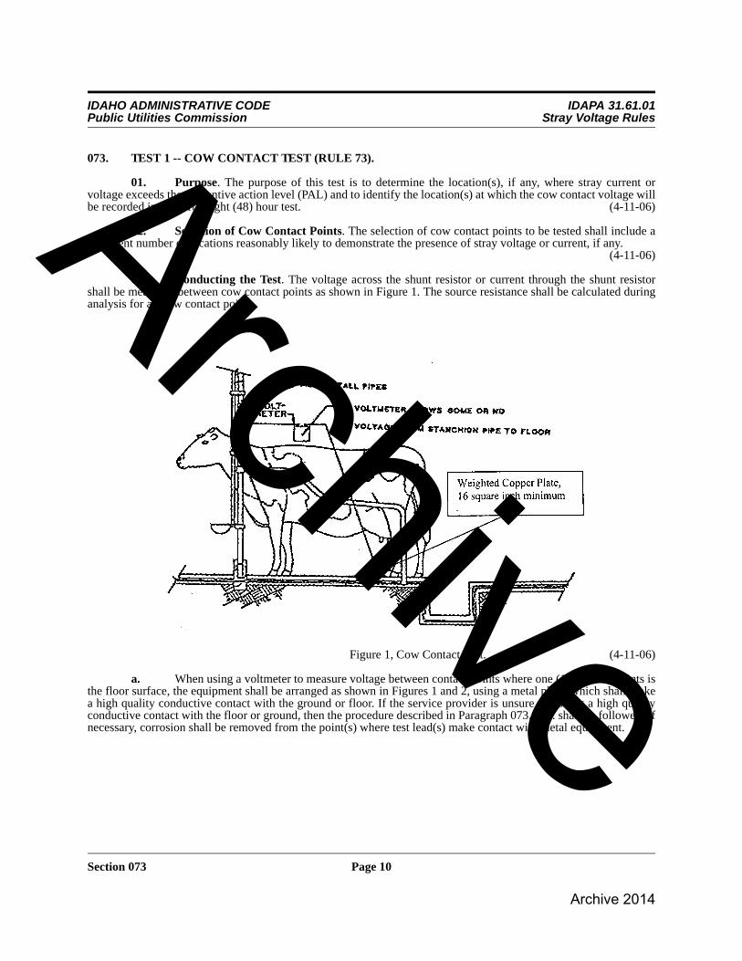
03. Conducting the Test. The voltage across the shunt resistor or current through the shunt resistor shall be measured between cow contact points as shown in Figure 1. The source resistance shall be calculated during analysis for all cow contact points.
Figure 1, Cow Contact Test. (4-11-06)
a. When using a voltmeter to measure voltage between contact points where one (1) of those points is the floor surface, the equipment shall be arranged as shown in Figures 1 and 2, using a metal plate, which shall make a high quality conductive contact with the ground or floor. If the service provider is unsure of having a high quality conductive contact with the floor or ground, then the procedure described in Paragraph 073.03.c. shall be followed. If necessary, corrosion shall be removed from the point(s) where test lead(s) make contact with metal equipment.
ArchiveArchive 2014

IDAHO ADMINISTRATIVE CODE IDAPA 31.61.01Public Utilities Commission Stray Voltage Rules
Section 073 Page 11
b. When using an in-line milliammeter or a clamp-around milliammeter to measure current between contact points and one (1) of those points is the floor surface or earth, the equipment shall be arranged as shown in Figure 3, using a metal plate which shall make high quality conductive contact with the ground or floor. If the service provider is unsure of having a high quality conductive contact with the floor or ground, then the procedures described in Paragraph 073.03.c. shall be followed. If necessary, corrosion shall be removed from the point(s) where test lead(s) make contact with metal equipment.
Figure 2, Cow Contact Voltage Measurement. (4-11-06)
ArchiveArchive 2014

IDAHO ADMINISTRATIVE CODE IDAPA 31.61.01Public Utilities Commission Stray Voltage Rules
Section 074 Page 12
c. A metal plate used to make an electrical contact with the earth or floor shall be of regular shape (square, rectangular or round), and shall have a surface area equal to or greater than sixteen (16) square inches (4 inches x 4 inches or equivalent). Place a weight not less than twenty (20) pounds on the metal plate. This weight shall be applied evenly across the metal plate and not to the adjacent concrete or earth. Place the metal plate a minimum distance of twelve (12) inches from any metal equipment making contact with the floor or earth. (4-11-06)
i. Where the metal plate is to be placed on a concrete floor, the surface shall be flat. Clean the floor surface with a wire brush to remove debris that may add excess resistance. Use water to clean the floor surface at the point where the metal plate will be placed. Place a paper towel or similar material soaked in saltwater between the metal plate and the concrete floor. (4-11-06)
ii. Where the metal plate is to be placed on the ground or earth surface, the surface shall be flat. Remove any debris and add water to the area, if necessary, to dampen the soil. The surface of the metal plate that will make contact with the earth shall be clean and free of corrosion before use. Remove any corrosion, if necessary.
(4-11-06)
04. Recording the Data. The person conducting this test shall record the location of, and measured values at, each test point. At each cow contact location, an open circuit voltage reading (Voc) and a voltage with five hundred (500) ohm nominal shunt resistor placed across the input to the meter shall be taken. These readings shall be taken with ten (10) seconds or less time between each reading. Alternatively, a current measurement
may be taken in place of the voltage reading . Data for these test points shall be recorded on the form in Appendix 1. (4-11-06)
05. Source Resistance Calculation. The source resistance shall be calculated for each cow contact location measured and the value recorded in Appendix 1. The following formulas shall be used to calculate source resistance.
(4-11-06)
074. TEST 2 -- FORTY-EIGHT HOUR TEST (RULE 74).
01. Purpose. The purpose of this test is to determine whether stray current or voltage exceeds the preventive action level (PAL) at selected location(s) over a forty-eight (48) hour period, subject to Subsection 074.06 and Paragraph 071.02.d. The test also demonstrates whether the primary or secondary sides of the system have a specific impact on the recorded current or voltage at specific times of day. (4-11-06)
02. Setup. A digitizing data recorder with averaging capability and capable of detecting and recording transient deviations of one-tenth (0.1) second or less in duration shall be used to record the following: (4-11-06)
a. Voltage from primary neutral at the transformer to remote reference ground, Vp. (4-11-06)
b. Voltage from secondary neutral in the service panel serving the area of the cow contact to remote reference ground, Vs. (4-11-06)
c. Voltage drops (Vps) from primary neutral at the location of connection for Vp to secondary neutral at the location of the connection for Vs. (4-11-06)
d. Cow contact current through (Icc) or voltage across a five hundred (500) ohm resistor at the high
Figure 3, Set Up for Measuring Current Cow Contact Point to Ground (4-11-06)
)(Vshunt
)(Ishunt )(Vshunt
)(Rsource
= Rsourceshunt
shunt
V
V - VocshuntRx
= Rsource I
Voc
shuntshuntR -
ArchiveArchive 2014

IDAHO ADMINISTRATIVE CODE IDAPA 31.61.01Public Utilities Commission Stray Voltage Rules
Section 075 Page 13
voltage point(s) found in Test 1, Vcc. (4-11-06)
03. Measurement Interval. The results of the forty-eight (48) hour test may be highly indicative of the presence of stray voltage. A recording interval as high as ten (10) seconds may be used provided that transient deviations of voltage or current of one-tenth (0.1) second or less in duration of voltage or current are recorded to the maximum ability of the instrument. (4-11-06)
04. Measurement at the Cow Contact Point(s). Measurements to the earth or concrete surface shall be to a metal plate as described in Paragraph 073.03.c. When making measurements to metal objects, corrosion shall be removed to obtain a low resistance connection. (4-11-06)
05. Recording the Data. All of the data gathered by the recording equipment during the forty-eight (48) hour test including transients shall be downloaded and retained with the records of the investigation. In addition, the steady-state data shall be summarized in the investigation report. The recorded data shall be made available to the dairy producer or utility upon request. The person conducting this test shall record the location of, and measured values at, each test point. The identification of the cow contact point shall be recorded on the form in Appendix 2. Transient deviations shall be recorded on the supplemental data form, page 3 of 3 in Appendix 2. A plot of the voltage versus time may be substituted for the recording of measured values in Appendix 2. (4-11-06)
06. Reduced Recording Period. If a qualified analyst concludes that remediation by the utility is required under Paragraph 071.02.d. prior to the completion of a forty-eight (48) hour recording period, the recording period may be reduced to no fewer than twenty-four (24) hours. (4-11-06)
075. TEST 3 -- PRIMARY PROFILE TEST (RULE 75).
01. Purpose. The purpose of this test is to measure or calculate neutral-to-earth voltage (NEV) for a multi-grounded distribution system. (4-11-06)
02. Conducting the Test. The primary profile test requires concurrent measurement of the ground electrode resistance and current at all primary system ground points within three quarters (3/4) of a mile on either side of all primary service points serving the dairy, or to the end of the line if less than three quarters (3/4) of a mile. Alternatively, the voltage between a remote grounding rod and the primary ground point being tested may be measured. (4-11-06)
a. This test shall be conducted starting at one (1) end of the distribution system and working toward the other end along the main primary distribution system. Figure 4 below illustrates the procedure. (4-11-06)
i. Where the dairy is served by a dedicated tap of less than one-half (1/2) mile in length from a distribution line, the neutral-to-earth voltage shall be measured at each primary ground along the tap and along the distribution line to a distance of three-quarters (3/4) of a mile in each direction from the point of the tap; or (4-11-06)
ii. Where a dairy is served by a dedicated tap that extends more than one-half (1/2) mile from the distribution line, the neutral-to-earth voltage shall be measured at each primary grounding electrode along the tap and along the distribution line to a distance of one-half (1/2) mile in each direction from the point of the tap. (4-11-06)
03. Recording the Data. The person conducting this test shall record the location of, and measured values at, each test point. Data and calculation results for these test points shall be recorded on the form in Appendix 3.
ArchiveArchive 2014

IDAHO ADMINISTRATIVE CODE IDAPA 31.61.01Public Utilities Commission Stray Voltage Rules
Section 076 Page 14
Figure 4, Primary Profile Test (4-11-06)
076. TEST 4 -- SECONDARY NEUTRAL VOLTAGE DROP TEST (RULE 76).
01. Purpose. This test is used to determine the impact of each secondary service on the neutral-to-earth (NEV) and cow contact voltages on the dairy under controlled conditions. (4-11-06)
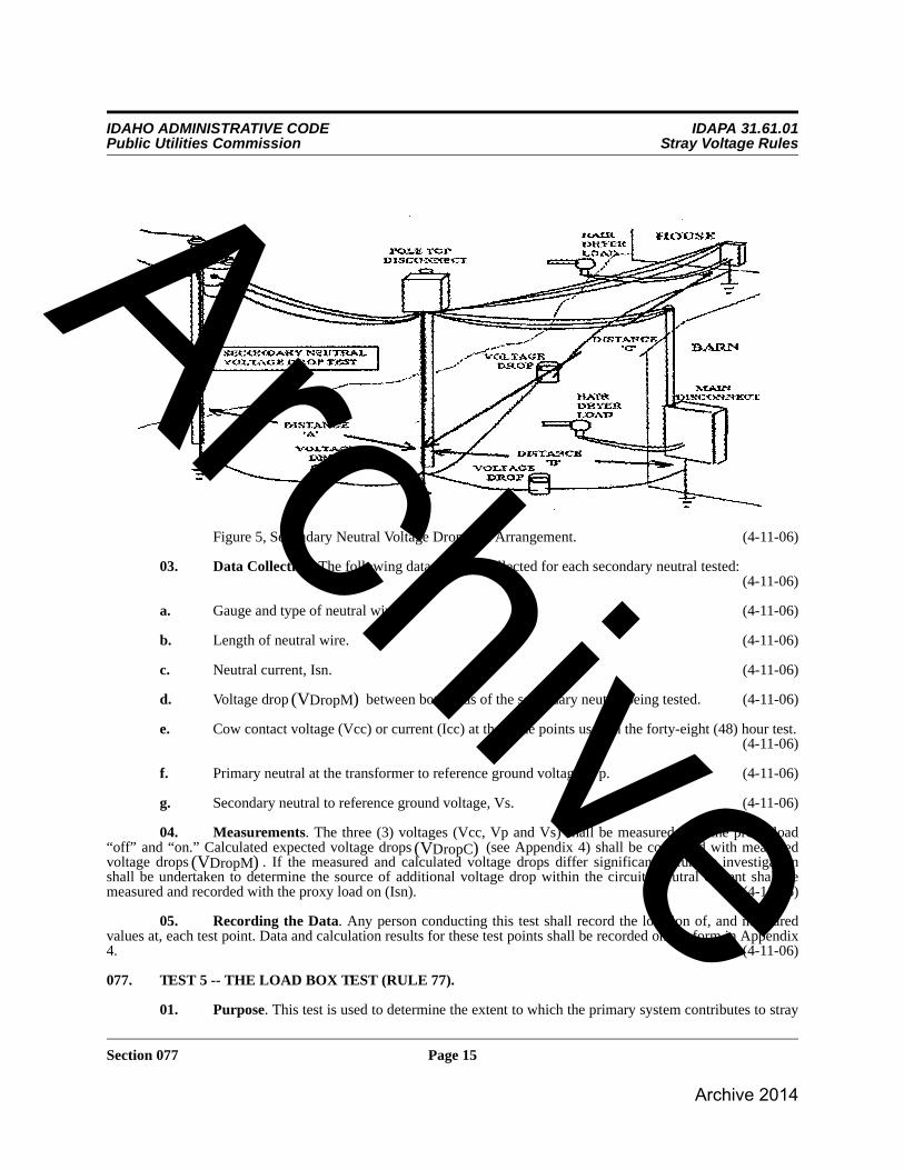
02. Conducting the Test. This test shall be performed for all service entrances. A proxy load of known characteristics (such as a resistive load like a one hundred twenty (120) volt, fifteen hundred (1,500) watt hairdryer) is required for this test. The proxy load must create a known and stable current and subsequent voltage drop for each neutral serving a main panel, sub-panel or end-of-service area. All service entrances other than that being tested shall be turned “off” to perform this test. A diagram showing the connections and measurement points for this test is shown in Figure 5.
ArchiveArchive 2014
IDAHO ADMINISTRATIVE CODE IDAPA 31.61.01Public Utilities Commission Stray Voltage Rules
Section 077 Page 15
Figure 5, Secondary Neutral Voltage Drop Test Arrangement. (4-11-06)
03. Data Collection. The following data shall be collected for each secondary neutral tested:(4-11-06)
a. Gauge and type of neutral wire. (4-11-06)
b. Length of neutral wire. (4-11-06)
c. Neutral current, Isn. (4-11-06)
d. Voltage drop between both ends of the secondary neutral being tested. (4-11-06)
e. Cow contact voltage (Vcc) or current (Icc) at the same points used in the forty-eight (48) hour test.(4-11-06)
f. Primary neutral at the transformer to reference ground voltage, Vp. (4-11-06)
g. Secondary neutral to reference ground voltage, Vs. (4-11-06)
04. Measurements. The three (3) voltages (Vcc, Vp and Vs) shall be measured with the proxy load “off” and “on.” Calculated expected voltage drops (see Appendix 4) shall be compared with measured voltage drops . If the measured and calculated voltage drops differ significantly, further investigation shall be undertaken to determine the source of additional voltage drop within the circuit. Neutral current shall be measured and recorded with the proxy load on (Isn). (4-11-06)
05. Recording the Data. Any person conducting this test shall record the location of, and measured values at, each test point. Data and calculation results for these test points shall be recorded on the form in Appendix 4. (4-11-06)
077. TEST 5 -- THE LOAD BOX TEST (RULE 77).
01. Purpose. This test is used to determine the extent to which the primary system contributes to stray
)(VDropM
)(VDropC)(VDropM
ArchiveArchive 2014

IDAHO ADMINISTRATIVE CODE IDAPA 31.61.01Public Utilities Commission Stray Voltage Rules
Section 077 Page 16
current or voltage at cow contact points. For dairies with three (3) phase balanced primary service, the service provider shall perform Steps One and Two in Paragraph 077.02.b. below. (4-11-06)
02. Conducting the Load Box Test. This test shall be performed at the same time of day as the time(s) of highest cow contact voltage found in the forty-eight (48) hour test. During this test, voltage and current shall be measured and recorded at the points indicated in Figure 6.
Figure 6, Load Box Test. (4-11-06)
a. The load box test requires the recording of eight (8) data points during each of the five (5) test steps. The eight (8) data points that shall be measured or calculated and recorded for each step are: (4-11-06)
i. Primary line to neutral voltage, . (4-11-06)
ii. Load Box Current, Ilb. (4-11-06)
iii. Voltage at load box connection to secondary system, Vlb. (4-11-06)
iv. Calculate transformer current using . (4-11-06)
v. Voltage from primary neutral at the transformer to remote reference ground rod, Vp. (4-11-06)
vi. Voltage from secondary neutral in the service panel serving the area of the cow contact to remote reference ground rod, Vs. (4-11-06)
vii. Voltage from primary neutral at the transformer to secondary neutral at the service panel serving the area of cow contact, Vps. (4-11-06)
viii. Cow contact voltage (Vcc) or current (Icc) at the same point(s) used in the forty-eight (48) hour test. (4-11-06)
priV
Ip = IppriV
Vlb x Ilb
ArchiveArchive 2014

IDAHO ADMINISTRATIVE CODE IDAPA 31.61.01Public Utilities Commission Stray Voltage Rules
Section 078 Page 17
b. Except for dairies with three (3) phase balanced primary service, the following five (5) test steps shall each be conducted for at least two (2) minutes: (4-11-06)
i. Step One: The load box shall be de-energized, the dairy shall remain “on,” and the data shall be recorded. (4-11-06)
ii. Step Two: The load box shall be de-energized, the dairy shut “off,” and the data shall be recorded.(4-11-06)
iii. Step Three: The load box shall be set to half load, the dairy shut “off,” and the data shall be recorded. (4-11-06)
iv. Step Four: The load box shall be set to full load, the dairy shut “off,” and the data shall be recorded.(4-11-06)
v. Step Five: The load box shall be set to full load, the dairy shall be turned “on,” and the data shall be recorded. (4-11-06)
03. Calculating the K Factor. The K factor is a calculated ratio (Vcc/Vs). The K factor should be less than one (1) because Vcc (cow contact voltage) should be less than Vs (the dairy ground to reference ground voltage). If the K factor is greater than one (1), then there is contribution to Vcc from sources other than Vs. (4-11-06)
04. Recording the Data. The person conducting this test shall record the location of, and measured values at, each test point. Data and calculation results for these test points shall be recorded on the form in Appendix 5. (4-11-06)
078. TEST 6 -- SIGNATURE TEST (RULE 78).
01. Purpose. This test is used to determine the contribution to stray current or voltage of individual pieces of equipment operating on the dairy. The test is best performed when there is minimal farm electrical activity.
(4-11-06)
02. Conducting the Signature Test. During this test, individual pieces of major current drawing equipment shall be started and stopped. The effects of starting, operating, and stopping each piece of equipment shall be measured and recorded for a period of operation of at least fifteen (15) seconds. The person conducting the test shall identify and record the equipment being tested and record the specific times that the equipment was started and stopped. A digitizing data recorder with averaging capability shall be used to measure and record the required electrical data. These measurements shall be taken at the same locations at the dairy where measurements were taken for the purpose of the load box test and forty-eight (48) hour test. (4-11-06)
a. Voltage from primary neutral at the transformer to remote reference ground rod, Vp. (4-11-06)
b. Secondary neutral at the service panel serving the area of cow contact to remote reference ground voltage, Vs. (4-11-06)
c. Primary neutral voltage drop (Vps) from the location of connection for Vp to secondary neutral voltage at the location of the connection for Vs. (4-11-06)
d. Cow contact voltage (Vcc) or current (Icc) at the preselected point. (4-11-06)
03. Recording the Data. All of the data gathered by the recording equipment during the signature test, including transients shall be downloaded and retained with the records of the investigation. In addition, the steady state data shall be summarized in the investigation report. The recorded data shall be made available to the dairy producer or utility upon request. The location of all test point(s) shall be recorded on the form in Appendix 6. A plot of the voltage versus time may be substituted for the recording of measured values on Appendix 6. (4-11-06)
079. -- 080. (RESERVED)
ArchiveArchive 2014

IDAHO ADMINISTRATIVE CODE IDAPA 31.61.01Public Utilities Commission Stray Voltage Rules
Section 081 Page 18
ANALYSIS AND REPORTING THE DATARULES 81 THROUGH 90
081. ANALYZING THE COLLECTED DATA (RULE 81).
01. Cow Contact Points. Examine the data recorded for the forty-eight (48) hour test in Appendix 2 and determine the highest steady state value of cow contact voltage (Vcc) or current (Icc). Determine the value of primary neutral to reference voltage (Vp) that was present for the highest cow contact value. Record these values on the data sheet of Appendix 7. These values shall be identified as “test cow contact voltage or current” ( or
) and “primary neutral to reference voltage at time of maximum cow contact voltage or current” ( ). The three (3) data sets created from the values are: (4-11-06)
a. The primary to reference ground voltage and the cow contact voltage or current measured during the load box test (Appendix 5) with the farm power “off” and the load box “off” shall be recorded on the data sheet of Appendix 7 as and either or . (4-11-06)
b. The primary to reference ground voltage and the cow contact voltage or current measured with the load box set at one-half (1/2) load shall be recorded on the data sheet of Appendix 7 as and either or . (4-11-06)
c. The primary to reference ground voltage and the cow contact voltage or current measured with the load box at maximum shall be recorded on the data sheet of Appendix 7 as and either or . (4-11-06)
02. Contributions to Stray Voltage or Current for Single Phase Dairies. The utility contribution to cow contact voltage or current shall be determined using the following formula. Compare the values determined to the preventive action level (PAL).
Utility contribution to
cow contact voltage =
or
Utility contribution to
cow contact current = (4-11-06)
03. Contributions to Stray Voltage or Current for Three Phase Dairies. The utility contribution to cow contact voltage or current for dairies with three (3) phase balanced load service, shall be determined by directly using the results of the load box test results for Step 1 and Step 2 as specified in Paragraph 077.02.b. (4-11-06)
a. The Vcc measured during Step 1 of the load box with the load box “off” and the dairy “on” will be the total Vcc. (4-11-06)
b. The Vcc measured during Step 2 of the load box test with the load box “off” and the dairy “off” is the contribution to Vcc from the utility, Vccutility. (4-11-06)
c. The contribution to Vcc by the dairy is the difference between Vcc and Vccutility, Vccdairy = Vcc - Vccutility. (4-11-06)
082. REPORTING (RULE 82).Within a reasonable period of time after completion of any tests required to be performed by the utility under these rules, a qualified analyst shall prepare a written report. The report shall include a summary of the tests performed, a
48hr Vcc48hr Icc48hr Vp
OFF Vp OFF Vcc OFF Icc
LOAD HALF VpLOAD HALF Vcc LOAD HALF Icc
LOAD FULL VpLOAD FULL Vcc LOAD FULL Icc
HALF FULL
HALF 48
Vp - Vp
Vp - Vp )Vcc - (Vccx HALF FULL HALF Vcc +
HALF FULL
HALF 48
Vp - Vp
Vp - Vp ) Icc - (Iccx HALFFULL HALF Icc +
ArchiveArchive 2014

IDAHO ADMINISTRATIVE CODE IDAPA 31.61.01Public Utilities Commission Stray Voltage Rules
Section 091 Page 19
copy of the sketch or drawing of the dairy prepared pursuant to Section 072, all of the data or results obtained from the tests, and an analysis of the data or results obtained from the tests. If remediation was required under these rules, the report shall specify the actions taken or to be taken. The utility shall provide a copy of the written report to the dairy producer. (4-11-06)
083. -- 090. (RESERVED)
REMEDIAL ACTIONS AND COMMISSION PROCEEDINGSRULES 91 THROUGH 92
091. REMEDIATION (RULE 91).
01. Utility System. If the utility is required to conduct remediation, it shall commence such remediation within five (5) business days. The utility shall diligently pursue to completion remedial procedures which shall reduce, and are reasonably likely to sustain, that portion of the stray current or voltage attributable to the utility’s distribution system to a level equal to or less than fifty percent (50%) of the preventive action level (PAL). This may include addressing other off-dairy sources. (4-11-06)
02. Other Dairies, Farms and Industrial Sites. If a utility’s contribution to stray voltage exceeds fifty percent (50%) of the preventive action level (PAL) and the utility determines that another customer is a significant contributing source of stray voltage, the utility shall notify both the dairy and the other customer in writing.(4-11-06)
092. COMMISSION PROCEEDINGS (RULE 92).
01. Filing with the Commission. All petitions seeking relief under Section 61-805, Idaho Code, shall be filed with the Commission Secretary pursuant to Section 005. Petitions shall conform to IDAPA 31.01.01, “Rules of Procedure of the Idaho Public Utilities Commission,” Section 053. The petitioner shall file an original and five (5) copies of the petition. (4-11-06)
02. Contents of Petition. The petition shall conform to IDAPA 31.01.01, “Rules of Procedure of the Idaho Public Utilities Commission,” Section 053. The petition shall contain background information, the date the notice was filed with the serving utility, a description of the alleged incident(s) of non-compliance with the Stray Current and Voltage Remediation Act, and the remediation actions (if any) undertaken by either the utility or the dairy. A copy of the utility’s entire stray voltage report shall accompany the petition. (4-11-06)
093. -- 999. (RESERVED)
APPENDIX 1TEST 1 – COW CONTACT POINT DATA FORM
Dairy Name: Date:Dairy Location:Shunt Resistor: ohm ( )
Item #
Contact Point
Identifier
Contact Point
Description
Voltage Measuredw/o Shunt Resistor
Voc
VoltageCurrent
Measured w/Shunt Resistor
Vcc
Source Resistance CalculatedRsource
Comments
1
2
shuntR
ArchiveArchive 2014

IDAHO ADMINISTRATIVE CODE IDAPA 31.61.01Public Utilities Commission Stray Voltage Rules
Section 092 Page 20
TEST 1 – COW CONTACT POINT DATA FORM INSTRUCTIONS
1. The total information provided by the contact point identification, the contact point description, and the dairy sketch(es) shall be sufficient to allow a third party to accurately repeat the test locating the correct cow contact points for a specific contact voltage.
2. The voltages measured in this test shall be determined using the same instrument(s) for both data points. One reading shall be taken immediately following the other using the same meter.
3. The actual source resistance is calculated from the known shunt resistance and the measured voltage.
4. Record comments as appropriate or necessary.
or
APPENDIX 2TEST 2 – “48-HOUR” TEST REPORT FORM 1
TEST 2 - “48-HOUR” TEST REPORT FORM 1INSTRUCTIONS
Record the following data with a long term digitizing data recorder or its equivalent for a minimum of 48 hours as specified in Rule 074:
a. Voltage from primary neutral to remote reference ground, Vp, at transformer.
b. Secondary neutral to remote reference ground voltage, Vs, at the electrical panel serving the area for the Vcc or Icc selected.
Customer Name: Date:Start Time: Stop Time:Contact Point Identifier Number
Hour
Time of Occurrence
(Hr, Min)of Highest
Steady StateVcc or Icc
Voltage Across (Current Thru)
Rshunt Vcc or Icc
Primary Neutral to Referenced
GroundVp
Secondary Neutral to Reference
GroundVs
Primary to Secondary
Voltage DropVps
Duration Steady State
Vcc or Icc Exceeded PAL
in One Hour Period
1
2
= Rsourceshunt
shunt
V
V - VocshuntRx shuntRx
= RsourceshuntI
Voc shuntR -
ArchiveArchive 2014

IDAHO ADMINISTRATIVE CODE IDAPA 31.61.01Public Utilities Commission Stray Voltage Rules
Section 092 Page 21
c. Primary neutral to secondary neutral voltage, Vps, between points of connection for Vp and Vs.
d. Steady state cow contact voltage or current at the preselected point(s) with the highest cow contact voltage or current recorded in Test 1, Vcc or Icc.
Steady State Data:
Steady state data recorded during the 48-hour test shall be presented in tabular format on Form 1 as described below, or it shall be presented graphically. Graphical presentation shall include a time scale for the entire recording period and a clear indication of the steady state readings of Vcc or Icc, Vp, Vs and Vps for the recording intervals. The scale(s) shall be such that steady state cow contact voltages or currents at or above the PAL are easily identifiable.
If using tabular format, the analyst shall enter data in the table for each hour of the 48 hours of the test in chronological order. The data recorded in the table shall include: the specific time that the highest steady state value of Vcc or Icc was recorded in that hour; all four corresponding data points recorded at that time (Vp, Vs, Vps and Vcc or Icc), and the total time during the hour that the steady state Vcc or Icc exceeded the PAL.
TEST 2 – REPORT FORM 2SUPPLEMENTAL DATA FOR FARM OWNER
TRANSIENT DEVIATIONS FOUND DURING “48-HOUR” TEST
Transient deviations occur due to electrical events such as motor starts. The PAL level is 1.0 volt for steady state voltages but PAL does not apply to transient voltage deviations.
TEST 2 - “48-HOUR” TEST REPORT FORM 2INSTRUCTIONS
Recording Transient Data:
For the purpose of identifying and reporting transient deviations, a transient deviation occurs when the recorded maximum Vcc or Icc in a recording interval exceeds two hundred percent (200%) of the steady state Vcc or Icc recording during the same recording interval.
Transient data recorded during the 48-hour test shall be presented in tabular format on the “48-hour Test – Transient Deviation Data” form as described below, or it shall be presented graphically. Graphical presentation shall
Customer Name: Date:
Start Time: Stop Time:
Contact Point Identifier Number:
HourTime of Highest
Peak Vcc (Icc)
Highest Voltage Recorded
Total NumberTransient
Deviations
No. Transient Deviations Exceeding 1.0 Volts with Peak Magnitude Greater
than 1.0 Volts (2.0 milliamps)
1
2
ArchiveArchive 2014
IDAHO ADMINISTRATIVE CODE IDAPA 31.61.01Public Utilities Commission Stray Voltage Rules
Section 092 Page 22
include a time scale for the entire recording period and a clear indication of the maximum Vcc or Icc recorded for the recording intervals. The scale(s) shall be such that Vcc transient deviations at or above two (2.0) volts, or Icc transient deviations at or above four (4) milliamps, are easily identifiable.
If using a tabular format, the analyst shall enter data in the table for each hour of the 48 hours of the test in chronological order. The data recorded in the table shall include; the specific time during the hour that the transient deviation in Vcc or Icc with the largest peak magnitude occurred, the corresponding peak Vcc or Icc, the total number of transient deviations recorded in that hour, and the total number of transient deviations recorded in that hour with a peak magnitude of two (2) or more volts for Vcc or four (4) or more milliamps for Icc.
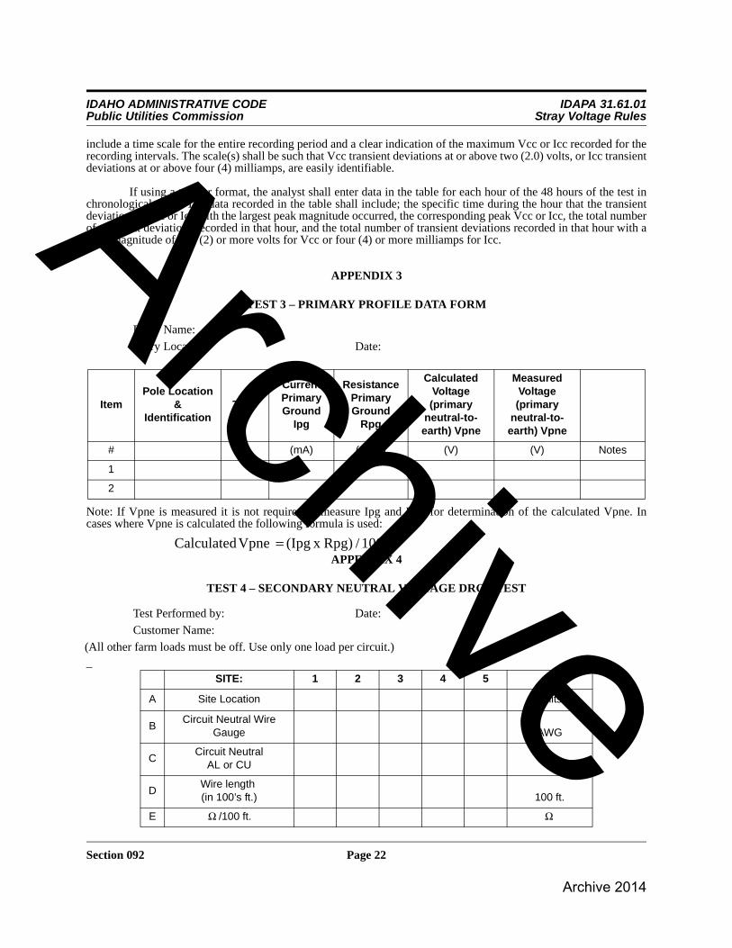
APPENDIX 3
TEST 3 – PRIMARY PROFILE DATA FORM
Note: If Vpne is measured it is not required to measure Ipg and Rpg for determination of the calculated Vpne. In cases where Vpne is calculated the following formula is used:
APPENDIX 4
TEST 4 – SECONDARY NEUTRAL VOLTAGE DROP TEST
_
Dairy Name:
Dairy Location: Date:
ItemPole Location
& Identification
Time
Current Primary Ground
Ipg
Resistance Primary Ground
Rpg
Calculated Voltage (primary
neutral-to-earth) Vpne
Measured Voltage (primary
neutral-to-earth) Vpne
# (mA) (Ohm) (V) (V) Notes
1
2
Test Performed by: Date:
Customer Name:
(All other farm loads must be off. Use only one load per circuit.)
SITE: 1 2 3 4 5
A Site Location Units
BCircuit Neutral Wire
Gauge AWG
CCircuit Neutral
AL or CU
DWire length (in 100’s ft.) 100 ft.
E /100 ft.
1000 / Rpg) x (Ipg Vpne Calculated =
Ω Ω
ArchiveArchive 2014

IDAHO ADMINISTRATIVE CODE IDAPA 31.61.01Public Utilities Commission Stray Voltage Rules
Section 092 Page 23
TEST 4 – SECONDARY NEUTRAL VOLTAGE DROP TESTINSTRUCTIONS
ITEM EXPLANATION
A-J Describe load site location, neutral wire gauge, neutral wire length (in 100s of feet), resistance per 100 feet (see table below), measured neutral current, measured voltage drop, Vp, Vs and Vcc or Icc for load “off” and load “on.”
Voltage drop is measured from end-to-end of the secondary neutral being tested and the neutral bus of the building being tested. Electrical power to all buildings shall be turned-off during this test except at the building being tested. Locations of Vp, Vs and Vcc or Icc are the same as measured during the previous tests.
Calculate the total circuit resistance. Calculate using Ohm’s Law, the expected neutral voltage drop. Calculate the absolute value of the difference and divide by the expected voltage drop. Express this as a percentage. If the two values (measured voltage drop and calculated voltage drop) do not agree, further investigation is warranted to discover the reason for the discrepancy.
FTotal Resistance
(D times E)
GMeasured Neutral
Current, Isn A
H
Calculated Voltage Drop,
(F times G)
V
IMeasured Voltage Drop,
V
JPercent difference
[(H-I)/H]*100 %
Vp load “off” V
Vs load “off” V
Vcc load “off” V
Icc load “off,”if measured
Vp load “on” V
Vs load “on” V
Vcc load “on” V
Icc load “on,”if measured
Ω
DropCV
DropMV
ArchiveArchive 2014

IDAHO ADMINISTRATIVE CODE IDAPA 31.61.01Public Utilities Commission Stray Voltage Rules
Section 092 Page 24
Resistance Chart (ohm per 100 feet)
Multi-conductor Cables at 68 Degrees F.
APPENDIX 5TEST 5 – LOAD BOX TEST
Date:________________________________
Time:_______________________________
Dairy:_______________________________
MATERIAL
GAUGE AL CU
14 0.423 0.257
12 0.265 0.162
10 0.166 0.102
8 0.104 0.064
6 0.066 0.040
4 0.042 0.025
2 0.026 0.016
1 0.021 0.013
1/0 0.016 0.010
2/0 0.013 0.008
3/0 0.010 0.007
4/0 0.008 0.005
STEP 1 STEP 2 STEP 3 STEP 4 STEP 5
FARM ON FARM OFF FARM OFF FARM OFF FARM ON
Condition Load BoxOff
Load BoxOff
Load BoxHalf On
Load BoxFull On
Load BoxFull On
Time:
Vp V V V V V
Vs V V V V V
Vps V V V V V
Vcc V V V V V
Icc A A A A A
ArchiveArchive 2014

IDAHO ADMINISTRATIVE CODE IDAPA 31.61.01Public Utilities Commission Stray Voltage Rules
Section 092 Page 25
TEST 5 - LOAD BOX TEST INSTRUCTIONS
Note 1: Testing may be accomplished by a single 18/25 kW load box or a dual element 9/18 or 12.5/25 kW load box. The difference between full load and half load measurements is used in most calculations.
Note 2: If the dairy is found in an isolated condition, two load box tests must be performed: an isolated test and a non-isolated test.
Note 3: If the dairy is served by a three-phase system, measure and record only the dairy-off, load box off column and the dairy-on, load box off column or test only one phase of the three.
ITEM EXPLANATION#
1 Enter date and customer name.
2 Attach load box to the 240-volt secondary side of transformer. Turn on load box and measure current and voltage and record on data sheet, Appendix 5.
3 Conduct load box test and for each step measure and record Vp, Vs, Vps and Vcc or Icc. Each step shall be maintained for approximately two minutes with the highest reading during that time interval recorded.
Step 1 Farm power is “on” with load box “off”
Step 2 Farm power is “off” with load box “off”
Step 3 Farm power is “off” with load box “on” at half load
Step 4 Farm power is “off” with load box “on” at full load
Step 5 Farm power is “on” with load box “on” full load
4 Remove load box and restore normal power to the farm.
Load Box Current (Ilb): Half Load A Full Load ALoad Box Voltage (Vlb): Half Load V Full Load V
Primary Nominal Voltage Phase to Neutral (Vpri): VTransformer Current Due to Load Box ( ):
Half Load A Full Load A
K-Factor for Cow Contact Point
XFMRI
Vpri
Vlb x Ilb= Ip
Vs
Vcc K=
ArchiveArchive 2014

IDAHO ADMINISTRATIVE CODE IDAPA 31.61.01Public Utilities Commission Stray Voltage Rules
Section 092 Page 26
APPENDIX 6
TEST 6 – EQUIPMENT SIGNATURE TEST FORM
TEST 6 - EQUIPMENT SIGNATURE TEST FORM INSTRUCTIONS
ITEM INSTRUCTIONS
1 Enter the date the test is performed.
2 Enter the name of the dairy.
3 Enter the description of the load for which the signature will be recorded.
4 Provide a complete description of the load. Provide voltage, horsepower or kilowatt rating, if known.
5 Note the time of turn-on and the time of turn-off. Equipment should be “on” for a period of not less than 15 seconds. If equipment is found in the “on” condition, turn it “off” then turn it back “on.” If equipment cannot be manually cycled then record data at the next “on” – “off” cycle.
6 Repeat for all major circuits and pieces of equipment (both 120 volt and 240 volt). Some equipment may normally be operated in sequence. Start each piece of equipment at 15-second intervals until all are running, then turn off in reverse order at 15-second intervals.
7 If data is to be provided graphically, only load description and time are required to be provided on Test 6 data sheet. Operation of each piece of equipment shall be indicated on the graphical data sheet(s).
APPENDIX 7
PREVENTIVE ACTION LEVEL RESULTS
Enter the highest value of cow contact voltage or current that occurred during the 48-hour test from Appendix 2, and corresponding primary to reference ground voltage.
Dairy Name:
Date:
Location:
Descr.of Load
Locationof Load
LoadV
LoadkW or
HP
LoadPhase1 or 3
Load On Load Off
Time Vp Vs Vps Vcc Icc Time Vp Vs Vps Vcc Icc
1
2
ArchiveArchive 2014

IDAHO ADMINISTRATIVE CODE IDAPA 31.61.01Public Utilities Commission Stray Voltage Rules
Section 092 Page 27
: __________V : __________V or : __________A
Enter the value of cow contact voltage or current and corresponding primary to reference ground voltage that was present during the load box test with the farm power off and the load box off.
: __________V : __________V or :___________A
Enter the value of cow contact voltage or current and corresponding primary to reference ground voltage that was present during the load box test with the farm power off and the load box set at half load.
: __________V : __________V or : __________A
Enter the value of cow contact voltage or current and corresponding primary to reference ground voltage that was present during the load box test with the farm power off and the load box at maximum.
: __________V : ___________V or : __________A
Calculations:
Utility Contribution to
Cow Contact Voltage =
Utility contribution to cow contact voltage =________________V
Utility contribution to cow contact voltage as a percentage of =_________________________%
Utility contribution to cow contact voltage as a percentage of PAL =_____________________%
Utility Contribution to
Cow Contact Current =
Utility contribution to cow contact current =_____________________mA (milliamps)
Utility contribution to cow contact current as a percentage of =__________________%
Utility contribution to cow contact current as a percentage of the PAL =____________________%
See Section 071.02 for required actions based on these results.
48hrVp 48hrVcc 48hr Icc
OFF Vp OFF Vcc OFF Icc
LOAD HALF Vp LOAD HALF Vcc LOAD HALF Icc
LOAD FULL Vp LOAD FULL Vcc LOAD FULL Icc
HALF FULL
HALF 48hr
Vp - Vp
Vp - Vp )Vcc - (Vccx HALF FULL HALF Vcc +
48hr Vcc
HALF FULL
HALF 48hr
Vp - Vp
Vp - Vp )Icc - (Iccx HALF FULL HALF Icc +
48hr Icc
ArchiveArchive 2014

Subject Index
Page 28
AAdmissibility 5Analyzing The Collected Data
18Contributions to Stray Voltage or
Current for Single Phase Dairies 18
Contributions to Stray Voltage or Current for Three Phase Dairies 18
Cow Contact Points 18
CCalibration of & Equipment Used for
Measuring & Recording Voltage, Current & Resistance 6
Calibration Requirements 6Calibration Certificates 7Field Check 7Measuring Equipment
Calibration 6Commission Proceedings
19Contents of Petition 19Filing with the Commission 19
DDairy Producer
5Cooperation 5Serving Notice on the Utility 5
Data Analysis 6Definitions, IDAPA 31.61.01
3Adequate Remediation 3Ampere 3Commission 3Cow Contact Points 3Equipotential Plane (EPP) 3Preventive Action Level (PAL) 3Primary System 4Secondary System 4Service Provider 4Shunt Resistor 4Source Resistance 4Steady State 4Stray Current or Voltage 4Tests, Measurements, Procedures
& Analysis 4Transient 4Utility 4
GGeneral Requirements For Stray
Voltage Measuring & Recording Equipment
6
Current Measurement 6Resistance Measurement 6Resistance-to-Earth
Measurement 6Resolution & Accuracy 6Voltage Measurement 6
PPerformance Of Tests & Measurements
5Master Electrician 5Professional Engineer 5Technician 6
Persons Otherwise Qualified 6Preparation For Testing
8In-Line Ammeters 9Inspecting the Transformer(s) 9Pre-Test Documentation 9Remote Reference Grounding
Rod 8Safety 9
Purpose Of Rules -- Conformance To Electrical Code
4Contributions to Stray Voltage 5Presence of Stray Voltage 5Sources of Stray Voltage 5
RRemedial Actions & Commission
Proceedings 19Remediation
19Other Dairies, Farms & Industrial
Sites 19Utility System 19
Reporting 18Requirements For Load Boxes
7Split-Load 7Volts 7
Requirements For Monitoring & Recording Devices 7
SService Providers 5Stray Current Or Voltage Tests
7Scheduling of Stray Voltage
Tests 7Suspended or Limited Testing 8Testing Sequence 8
TTest 1 -- Cow Contact Test
10Conducting the Test 10
Purpose 10Recording the Data 12Selection of Cow Contact
Points 10Source Resistance
Calculation 12Test 2 -- Forty-Eight Hour Test
12Measurement at the Cow Contact
Point(s) 13Measurement Interval 13Purpose 12Recording the Data 13Reduced Recording Period 13Setup 12
Test 3 -- Primary Profile Test 13Conducting the Test 13Purpose 13Recording the Data 13
Test 4 -- Secondary Neutral Voltage Drop Test
14Conducting the Test 14Data Collection 15Measurements 15Purpose 14Recording the Data 15
Test 5 -- The Load Box Test 15Calculating the K Factor 17Conducting the Load Box
Test 16Purpose 15Recording the Data 17
Test 6 -- Signature Test 17Conducting the Signature Test 17Purpose 17Recording the Data 17
Testing & measurement Procedures 7
UUtility 5
ArchiveArchive 2014