Embed Size (px)
Citation preview
____________________________________________________________ __________ SMLayout CAD-CIM Tech. (219) 614-7235 www.cadcim.com Page-1
TABLE OF CONTENTS 1. Introduction 2. Limitation of Liability 3. Installation of SMLayout Software 4. Sheet Metal Development
A. SHEET METAL A. Rectangle to Rectangle Transition
TRANA Generates Layout of Rectangle to Rectangle
Transition without offset. TRANAO Generates Layout of Rectangle to Rectangle
Transition with offset. TRANAOO Generates Layout of Rectangle to Rectangle
Transition with offset and top rectangle inclined at an angle.
B. Rectangle to Circle Transition
TRANB Generates Layout of Rectangle to Circle Transition. TRANBXO Generates Layout of Rectangle to Circle Transition
with offset. TRANBAO Generates Layout of Rectangle to Circle Transition
with offset and circle inclined at an angle.
C. Cones Development
STCONE (Single Truncated Cone)
____________________________________________________________ __________ SMLayout CAD-CIM Tech. (219) 614-7235 www.cadcim.com Page-2
This program generates a flat layout of a single truncated cone that is cut at an angle at the top.
DTCONE (Double Truncated Cone) This program generates a flat layout of a double
truncated cone that is cut at an angle at the top and at the bottom.
CONE-S Generates Layout of a CONE, in several predefined
number of pieces and cutting allowance, along the length of a rectangular sheet.
CONE-60
Generates Layout of a CONE in two identical
pieces along the diagonal of a rectangular piece. CONE-2PS Generates Layout of a CONE in two identical
pieces along the length of a rectangular sheet. CONE-1P Generates Layout of a CONE in a single piece. CONE-OF Generates Single Piece Layout of a CONE with
offset. CONE-2OF Generates Single Piece Layout of a CONE with
offset and Cut Top.
D. Cone-Cylinder Intersection
CONCYLP Generates Layout of CYLINDER for Cone-
Cylinder intersection with parallel axis. CONCYLPX Generates Layout of HOLE in the Cone, for Cone-
Cylinder Intersection with parallel axis. CONCYLT Generates Layout of CYLINDER for Cone-
Cylinder intersection with the axis at 90 Degrees. CONCYLTX
____________________________________________________________ __________ SMLayout CAD-CIM Tech. (219) 614-7235 www.cadcim.com Page-3
Generates Layout of HOLE in the Cone, for Cone-Cylinder intersection with the axis at 90 degrees.
E. Cylinder - Sphere Intersection
CYLSPHR Generates Layout of CYLINDER for Sphere
Cylinder intersection. F. Cylinder - Cylinder Intersection
CYLCYLB Generates Layout of CYLINDER for a Cylinder-
Cylinder intersection when the cylinders are at an angle without any offset.
CYLCYLC Generates Layout of CYLINDER for a Cylinder-
Cylinder intersection when the cylinders are offset and are intersecting at 90 degrees.
CYLCYLD Generates Layout of CYLINDER for Cylinder-
Cylinder intersection when the cylinders are offset and intersecting at an angle.
CYLCYLF Generates Layout of Cylinder for Cylider-Cylinder
intersection when the cylinders intersect at their ends, like a picture frame.
CYLHOLE Generate flat layout of hole in a cylinder for
cylinder-cylinder intersection. The cylinders can be offset and intersecting at an angle
CYLCFLAT Generates Layout of Cylinder when the cylinder
intersects with a flat surface. CYLFLATH This program generates the shape of the hole in the
flat plate for a cylinder to flat plate intersection.
THSELL1 This program generates flat layout of a cylindrical
tank shell and the hole: a hole where the pipe intersects with the tank shell.
____________________________________________________________ __________ SMLayout CAD-CIM Tech. (219) 614-7235 www.cadcim.com Page-4
G. Pyramid Development
PYRAMID1 Generates a Single Piece Layout of a multi sided
PYRAMID with offset. PYRAMID2 Generates a Single Piece Layout of a multi sided
PYRAMID with offset and cut top.
H. Boxes and Elbows Development
BOXR Generates Layout of a Rectangular Box. ELBOW1 Generates Layout of an ELBOW with a predefined
elbow angle. TELBOW (TAPERED ELBOW) This program calculates various parameters for an
elbow that is tapered. The program also draws the tapered elbow on the screen and automatically dimensions it.
B. TANK HEADS
FLATA This program generates the strip layout of a flat
circular plate with a hole in the center. SHCONE1 This program generates the strip layout of a shallow
cone with open top. HEMIS1 This program generates the flat strip layout of a
hemispherical dish. DISH1 This program generates the flat strip layout of a
spherical tank head. DISHK This program generates a flat strip layout of a
spherical dish with a knuckle radius.

____________________________________________________________ __________ SMLayout CAD-CIM Tech. (219) 614-7235 www.cadcim.com Page-5
INTRODUCTION
SMLayout
(Sheet Metal Layout)
SMLayout addresses the needs of sheet metal fabricators and manufacturers of sheet metal products to generate flat layout of some complicated geometric shapes. Written in AutoLISP, SMLayout can develop flat layout of cones, cylinders, elbows, rectangular boxes, transitions, cone-cylinder intersections, sphere-cylinder intersections, cylinder-cylinder intersections, and various shapes of Tank-Heads. The programs have a dimensioning option that will automatically dimension the flat layout. SMLayout comes with a menu file that gives the user an option to select a program from a screen menu or a pull-down menu. The user is prompted to enter information about the part geometry, and then the program automatically generates the flat layout on the computer screen. A detailed explanation of the part geometry and the input parameters is contained in this manual. SMLayout is easy to use and the programs do not need any 2D or 3D drawings. The layout contains intelligent vector information that can be down loaded to a CNC machine through a CAD/CAM interface.

____________________________________________________________ __________ SMLayout CAD-CIM Tech. (219) 614-7235 www.cadcim.com Page-6
LIMITATION OF LIABILITY In no event will CAD-CIM Technologies be liable for any damage, including loss of data, loss of profits or other special, incidental, consequential or indirect damages arising from the use of the programs or accompanying documentation, however caused and on any theory of liability. Please sign the enclosed License Agreement and mail it to CAD-CIM Technologies. After we receive the License Agreement, you will be entitled to receive the following:
1. One year free update.
For more information, please call:
CADCIM Technologies 525 St. Andrews Drive Schererville, IN 46375
TEL:- (219) 614-7235
Note: It is strongly recommended that you first test the programs before cutting the material.

____________________________________________________________ __________ SMLayout CAD-CIM Tech. (219) 614-7235 www.cadcim.com Page-7
INSTALLATION and LOADING
SMLayout (Sheet Metal Layout Software)
Loading Programs from the SMLayout Diskette
Start AutoCAD and then enter the following command at AutoCAD's Command: prompt:
Command: (load "A:\\TRANB")
In this example it is assumed that you want to load the TRANB program from the SMLayout diskette placed in A drive. When you press the Enter key, AutoCAD will return the name of the function (TRANB for this example). To run the program enter the name of the function at the Command: prompt. Command: TRANB However, the best and the easiest way to load the programs is to use AutoCAD's APPLOAD command to load the programs. When you invoke this command, AutoCAD displays the Load/Unload Applications dialog box. You can use this dialog box to load the programs.
Installing SMLayout on Hard Drive
You can also copy the programs to the hard drive and then load the programs from drive.

____________________________________________________________ __________ SMLayout CAD-CIM Tech. (219) 614-7235 www.cadcim.com Page-8
Please Note:
1. The information you enter should be mathematically correct and realistic. 2. The programs automatically set the dimensioning scale factor to an
appropriate value so as to display the dimensions to correct size. 3. All the dimensions should be entered in decimal format like, 13.065. 4. Before running the program, set the limits so that the entire drawing is
displayed on the screen. 5. Sometime, you might get "Unknown Command", "Insufficient node space" or
"Insufficient string space" messages. Check your LISPSTACK and LISPHEAP values or quit and then get back into the drawing editor. Now you can load and run the programs again.
Note: It is strongly recommended that you first test the programs before cutting the material.
____________________________________________________________ __________ SMLayout CAD-CIM Tech. (219) 614-7235 www.cadcim.com Page-9
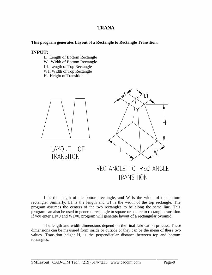
TRANA This program generates Layout of a Rectangle to Rectangle Transition. INPUT: L. Length of Bottom Rectangle W. Width of Bottom Rectangle L1. Length of Top Rectangle W1. Width of Top Rectangle H. Height of Transition
L is the length of the bottom rectangle, and W is the width of the bottom rectangle. Similarly, L1 is the length and w1 is the width of the top rectangle. The program assumes the centers of the two rectangles to be along the same line. This program can also be used to generate rectangle to square or square to rectangle transition. If you enter L1=0 and W1=0, program will generate layout of a rectangular pyramid. The length and width dimensions depend on the final fabrication process. These dimensions can be measured from inside or outside or they can be the mean of these two values. Transition height H, is the perpendicular distance between top and bottom rectangles.
____________________________________________________________ __________ SMLayout CAD-CIM Tech. (219) 614-7235 www.cadcim.com Page-10
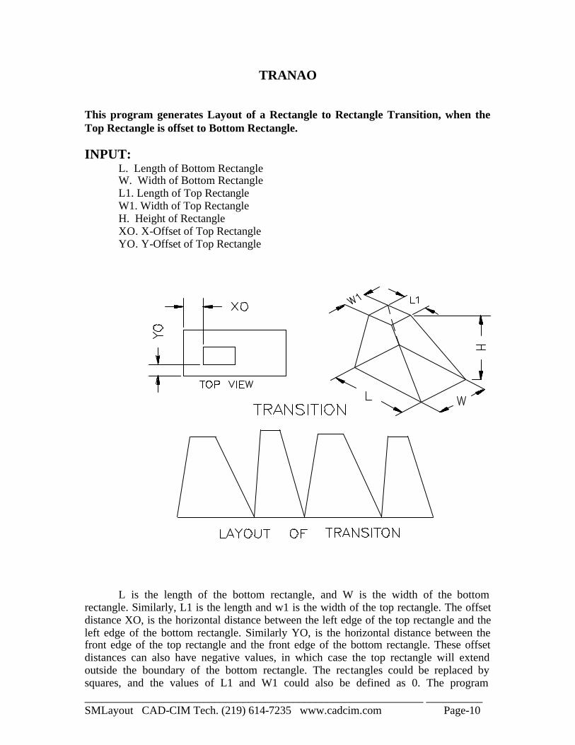
TRANAO This program generates Layout of a Rectangle to Rectangle Transition, when the Top Rectangle is offset to Bottom Rectangle. INPUT: L. Length of Bottom Rectangle W. Width of Bottom Rectangle L1. Length of Top Rectangle W1. Width of Top Rectangle H. Height of Rectangle XO. X-Offset of Top Rectangle YO. Y-Offset of Top Rectangle
L is the length of the bottom rectangle, and W is the width of the bottom rectangle. Similarly, L1 is the length and w1 is the width of the top rectangle. The offset distance XO, is the horizontal distance between the left edge of the top rectangle and the left edge of the bottom rectangle. Similarly YO, is the horizontal distance between the front edge of the top rectangle and the front edge of the bottom rectangle. These offset distances can also have negative values, in which case the top rectangle will extend outside the boundary of the bottom rectangle. The rectangles could be replaced by squares, and the values of L1 and W1 could also be defined as 0. The program

____________________________________________________________ __________ SMLayout CAD-CIM Tech. (219) 614-7235 www.cadcim.com Page-11
automatically dimensions the layout. Caution should be exercised when matching the edges before welding. The length and width dimensions depend on the final fabrication process. These dimensions could be measured from inside or outside or they could be the mean of these two values. Transition height H, is the perpendicular distance between the top and bottom rectangles.
____________________________________________________________ __________ SMLayout CAD-CIM Tech. (219) 614-7235 www.cadcim.com Page-12
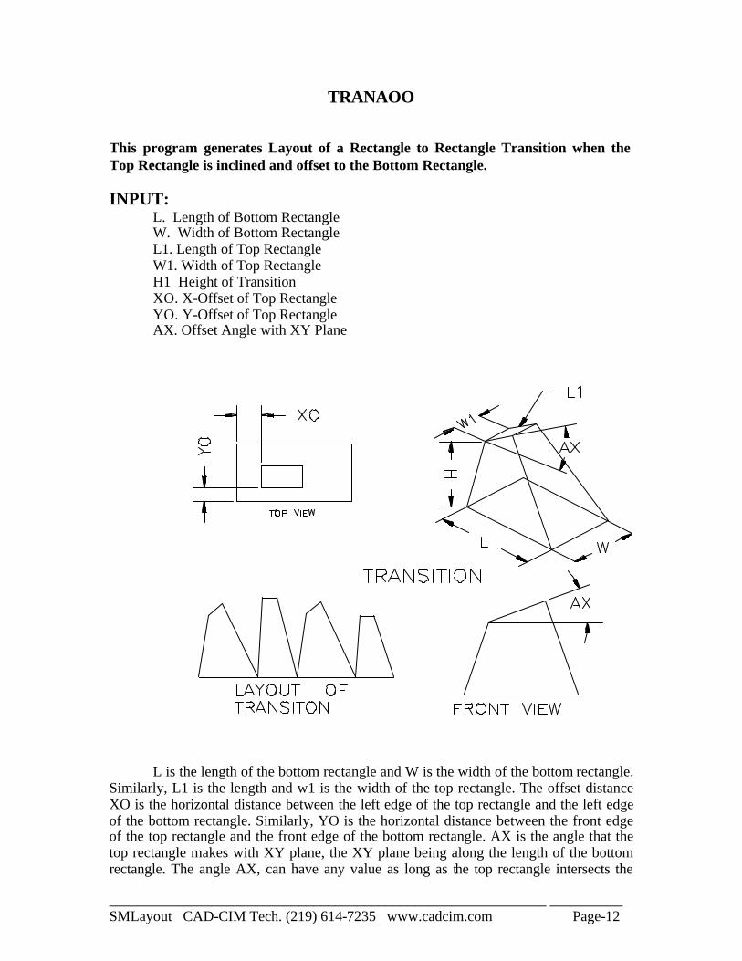
TRANAOO This program generates Layout of a Rectangle to Rectangle Transition when the Top Rectangle is inclined and offset to the Bottom Rectangle. INPUT: L. Length of Bottom Rectangle W. Width of Bottom Rectangle L1. Length of Top Rectangle W1. Width of Top Rectangle H1 Height of Transition XO. X-Offset of Top Rectangle YO. Y-Offset of Top Rectangle AX. Offset Angle with XY Plane
L is the length of the bottom rectangle and W is the width of the bottom rectangle. Similarly, L1 is the length and w1 is the width of the top rectangle. The offset distance XO is the horizontal distance between the left edge of the top rectangle and the left edge of the bottom rectangle. Similarly, YO is the horizontal distance between the front edge of the top rectangle and the front edge of the bottom rectangle. AX is the angle that the top rectangle makes with XY plane, the XY plane being along the length of the bottom rectangle. The angle AX, can have any value as long as the top rectangle intersects the

____________________________________________________________ __________ SMLayout CAD-CIM Tech. (219) 614-7235 www.cadcim.com Page-13
left side of the transition. Otherwise, the program will terminate without generating layout. The offset distances can also have negative values, in which case the top rectangle will extend outside the boundary of the bottom rectangle. The rectangles could be replaced by squares, and the values of L1 and W1 could be defined as 0. The program automatically dimensions the layout. Caution should be exercised when matching the edges before welding. The length and width dimensions depend on the final fabrication process. These dimensions could be measured from inside or outside or they could be the mean of these two values. Transition height H is the perpendicular distance between the top and bottom rectangles.
____________________________________________________________ __________ SMLayout CAD-CIM Tech. (219) 614-7235 www.cadcim.com Page-14
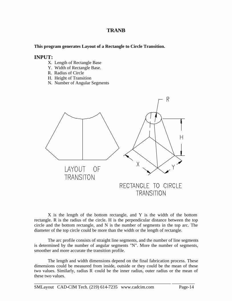
TRANB This program generates Layout of a Rectangle to Circle Transition. INPUT: X. Length of Rectangle Base Y. Width of Rectangle Base. R. Radius of Circle H. Height of Transition N. Number of Angular Segments
X is the length of the bottom rectangle, and Y is the width of the bottom rectangle. R is the radius of the circle. H is the perpendicular distance between the top circle and the bottom rectangle, and N is the number of segments in the top arc. The diameter of the top circle could be more than the width or the length of rectangle. The arc profile consists of straight line segments, and the number of line segments is determined by the number of angular segments "N". More the number of segments, smoother and more accurate the transition profile. The length and width dimensions depend on the final fabrication process. These dimensions could be measured from inside, outside or they could be the mean of these two values. Similarly, radius R could be the inner radius, outer radius or the mean of these two values.
____________________________________________________________ __________ SMLayout CAD-CIM Tech. (219) 614-7235 www.cadcim.com Page-15
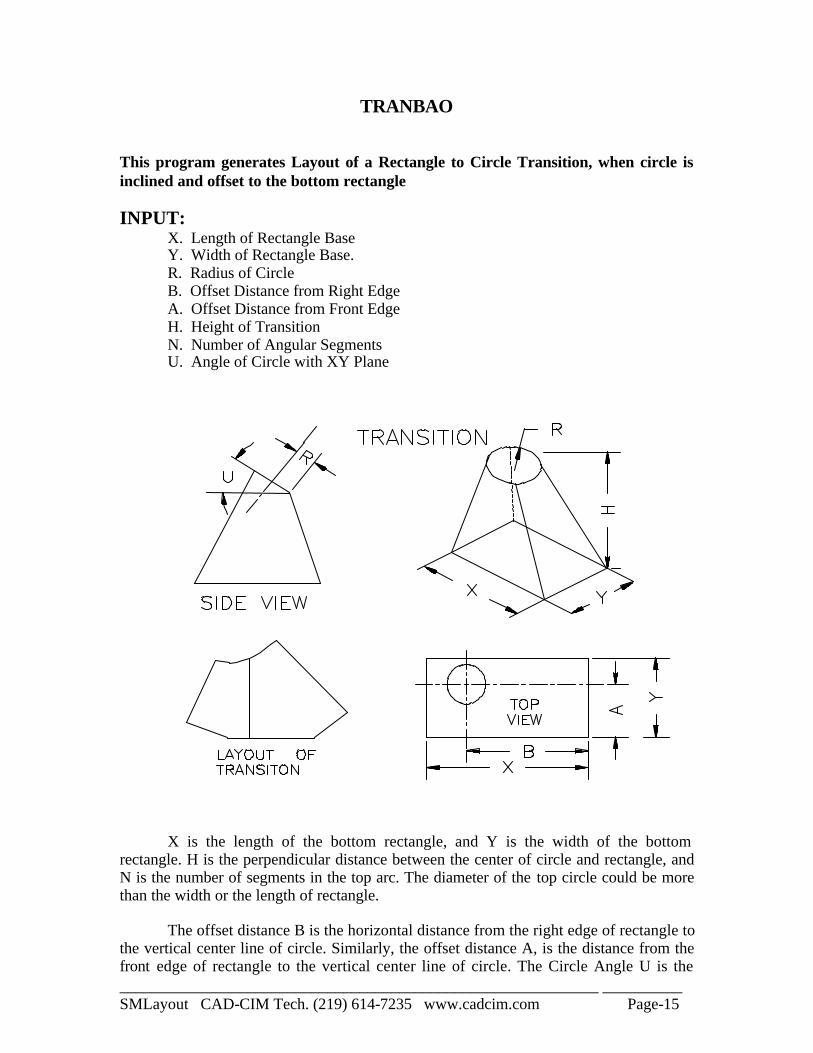
TRANBAO This program generates Layout of a Rectangle to Circle Transition, when circle is inclined and offset to the bottom rectangle INPUT: X. Length of Rectangle Base Y. Width of Rectangle Base. R. Radius of Circle B. Offset Distance from Right Edge A. Offset Distance from Front Edge H. Height of Transition N. Number of Angular Segments U. Angle of Circle with XY Plane
X is the length of the bottom rectangle, and Y is the width of the bottom rectangle. H is the perpendicular distance between the center of circle and rectangle, and N is the number of segments in the top arc. The diameter of the top circle could be more than the width or the length of rectangle. The offset distance B is the horizontal distance from the right edge of rectangle to the vertical center line of circle. Similarly, the offset distance A, is the distance from the front edge of rectangle to the vertical center line of circle. The Circle Angle U is the
____________________________________________________________ __________ SMLayout CAD-CIM Tech. (219) 614-7235 www.cadcim.com Page-16
angle that circle makes with the horizontal plane. The value of this angle should be smaller than the angle of the left or right face. Otherwise, the program will terminate without developing the layout. R is radius of circle along the plane of circle. NOTE: To develop Layout of the back half of transition, measure the offset distance "A" from the back edge instead of the front edge. The offset distance "B" remains same. Make sure you bend the pieces in the proper direction to get the right shape of the transition. The length and width dimensions depend on the final fabrication process. These dimensions could be measured from inside, outside or they could be the mean of these two values. Similarly, radius R could be the inner radius, outer radius or the mean of these two values. The arc profile consists of straight line segments, and the number of line segments is determined by the number of angular segments "N". More the number of segments, smoother and more accurate the transition profile.
____________________________________________________________ __________ SMLayout CAD-CIM Tech. (219) 614-7235 www.cadcim.com Page-17
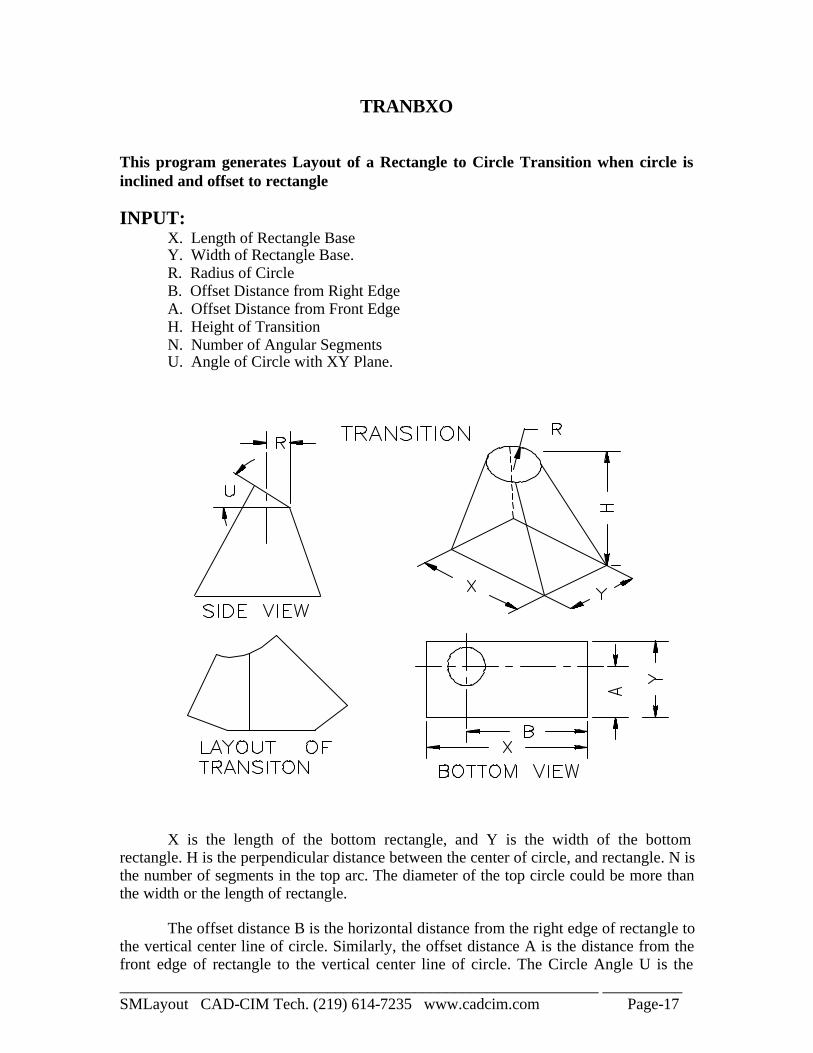
TRANBXO This program generates Layout of a Rectangle to Circle Transition when circle is inclined and offset to rectangle INPUT: X. Length of Rectangle Base Y. Width of Rectangle Base. R. Radius of Circle B. Offset Distance from Right Edge A. Offset Distance from Front Edge H. Height of Transition N. Number of Angular Segments U. Angle of Circle with XY Plane.
X is the length of the bottom rectangle, and Y is the width of the bottom rectangle. H is the perpendicular distance between the center of circle, and rectangle. N is the number of segments in the top arc. The diameter of the top circle could be more than the width or the length of rectangle. The offset distance B is the horizontal distance from the right edge of rectangle to the vertical center line of circle. Similarly, the offset distance A is the distance from the front edge of rectangle to the vertical center line of circle. The Circle Angle U is the
____________________________________________________________ __________ SMLayout CAD-CIM Tech. (219) 614-7235 www.cadcim.com Page-18
angle that circle makes with the horizontal plane. The value of this angle should be smaller than the angle of the left or the right face. Otherwise, the program will terminate without developing the layout. R is the radius of circle along the horizontal plane. To develop the Layout of the back half of transition, measure the distance "A" from the back edge instead of the front edge. The offset distance "B" remains same. Make sure you bend the pieces in proper direction to get the right shape of the transition. The length and width dimensions depend on the final fabrication process. These dimensions could be measured from inside, outside or they could be the mean of these two values. Similarly, radius R could be the inner radius, outer radius or the mean of these two values. The arc profile consists of straight line segments, and the number of line segments is determined by the number of angular segments "N". More the number of segments, smoother and more accurate the transition profile.
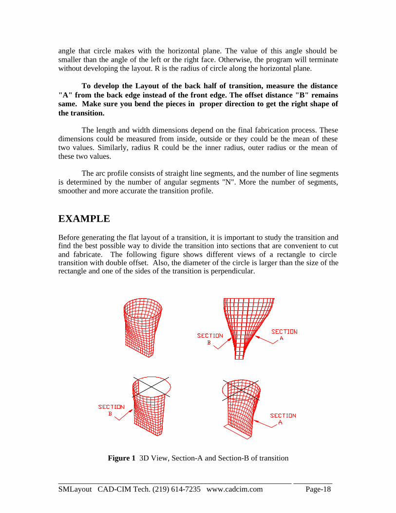
EXAMPLE Before generating the flat layout of a transition, it is important to study the transition and find the best possible way to divide the transition into sections that are convenient to cut and fabricate. The following figure shows different views of a rectangle to circle transition with double offset. Also, the diameter of the circle is larger than the size of the rectangle and one of the sides of the transition is perpendicular.
Figure 1 3D View, Section-A and Section-B of transition
____________________________________________________________ __________ SMLayout CAD-CIM Tech. (219) 614-7235 www.cadcim.com Page-19
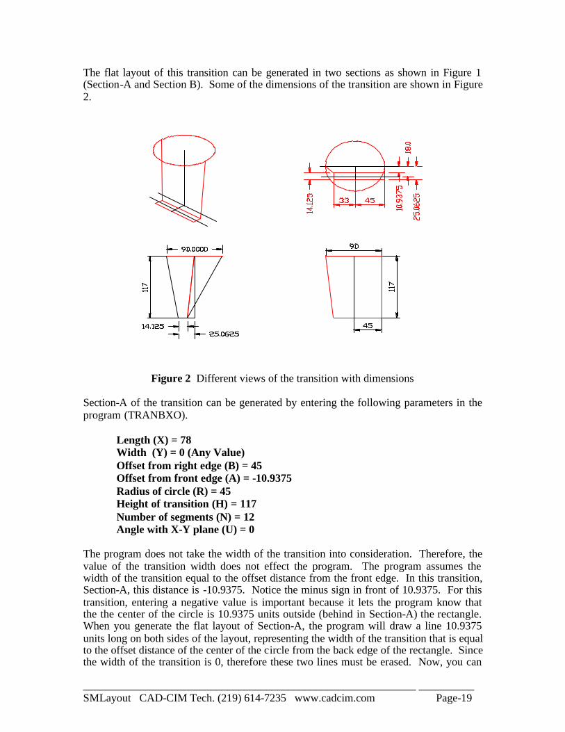
The flat layout of this transition can be generated in two sections as shown in Figure 1 (Section-A and Section B). Some of the dimensions of the transition are shown in Figure 2.
Figure 2 Different views of the transition with dimensions Section-A of the transition can be generated by entering the following parameters in the program (TRANBXO).
Length (X) = 78 Width (Y) = 0 (Any Value) Offset from right edge (B) = 45 Offset from front edge (A) = -10.9375 Radius of circle (R) = 45 Height of transition (H) = 117 Number of segments (N) = 12 Angle with X-Y plane (U) = 0
The program does not take the width of the transition into consideration. Therefore, the value of the transition width does not effect the program. The program assumes the width of the transition equal to the offset distance from the front edge. In this transition, Section-A, this distance is -10.9375. Notice the minus sign in front of 10.9375. For this transition, entering a negative value is important because it lets the program know that the the center of the circle is 10.9375 units outside (behind in Section-A) the rectangle. When you generate the flat layout of Section-A, the program will draw a line 10.9375 units long on both sides of the layout, representing the width of the transition that is equal to the offset distance of the center of the circle from the back edge of the rectangle. Since the width of the transition is 0, therefore these two lines must be erased. Now, you can
____________________________________________________________ __________ SMLayout CAD-CIM Tech. (219) 614-7235 www.cadcim.com Page-20
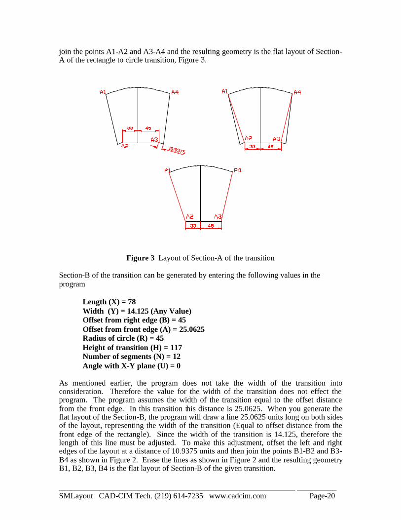
join the points A1-A2 and A3-A4 and the resulting geometry is the flat layout of Section-A of the rectangle to circle transition, Figure 3.
Figure 3 Layout of Section-A of the transition
Section-B of the transition can be generated by entering the following values in the program
Length (X) = 78 Width (Y) = 14.125 (Any Value) Offset from right edge (B) = 45 Offset from front edge (A) = 25.0625 Radius of circle (R) = 45 Height of transition (H) = 117 Number of segments (N) = 12 Angle with X-Y plane (U) = 0
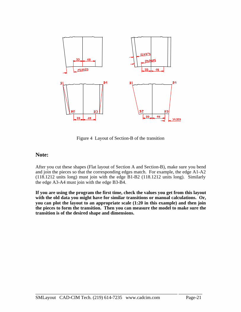
As mentioned earlier, the program does not take the width of the transition into consideration. Therefore the value for the width of the transition does not effect the program. The program assumes the width of the transition equal to the offset distance from the front edge. In this transition this distance is 25.0625. When you generate the flat layout of the Section-B, the program will draw a line 25.0625 units long on both sides of the layout, representing the width of the transition (Equal to offset distance from the front edge of the rectangle). Since the width of the transition is 14.125, therefore the length of this line must be adjusted. To make this adjustment, offset the left and right edges of the layout at a distance of 10.9375 units and then join the points B1-B2 and B3-B4 as shown in Figure 2. Erase the lines as shown in Figure 2 and the resulting geometry B1, B2, B3, B4 is the flat layout of Section-B of the given transition.
____________________________________________________________ __________ SMLayout CAD-CIM Tech. (219) 614-7235 www.cadcim.com Page-21
Figure 4 Layout of Section-B of the transition
Note: After you cut these shapes (Flat layout of Section A and Section-B), make sure you bend and join the pieces so that the corresponding edges match. For example, the edge A1-A2 (118.1212 units long) must join with the edge B1-B2 (118.1212 units long). Similarly the edge A3-A4 must join with the edge B3-B4. If you are using the program the first time, check the values you get from this layout with the old data you might have for similar transitions or manual calculations. Or, you can plot the layout to an appropriate scale (1:20 in this example) and then join the pieces to form the transition. Then you can measure the model to make sure the transition is of the desired shape and dimensions.
____________________________________________________________ __________ SMLayout CAD-CIM Tech. (219) 614-7235 www.cadcim.com Page-22
STCONE
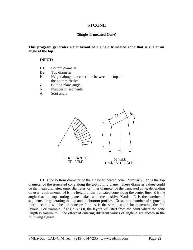
(Single Truncated Cone) This program generates a flat layout of a single truncated cone that is cut at an angle at the top.
INPUT: D1 Bottom diameter D2 Top diameter H Height along the center line between the top and the bottom circles Z Cutting plane angle N Number of segments A Start angle
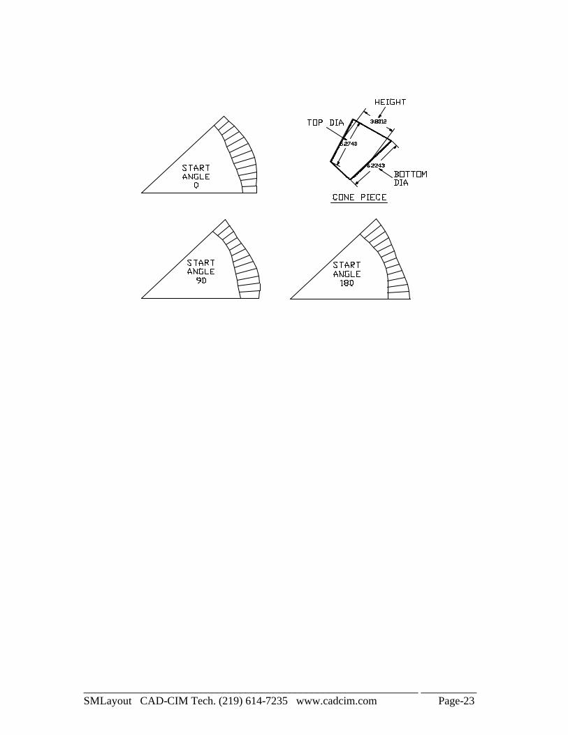
D1 is the bottom diameter of the single truncated cone. Similarly, D2 is the top diameter of the truncated cone along the top cutting plane. These diameter values could be the mean diameter, outer diameter, or inner diameter of the truncated cone, depending on user requirements. H is the height of the truncated cone along the center line. Z is the angle that the top cutting plane makes with the positive X-axis. N is the number of segments for generating the top and the bottom profiles. Greater the number of segments, more accurate will be the cone profile. A is the staring angle for generating the flat layout. For example, if angle A is 0, the layout will start from the point where the cone length is minimum. The effect of entering different values of angle A are shown in the following figures.
____________________________________________________________ __________ SMLayout CAD-CIM Tech. (219) 614-7235 www.cadcim.com Page-23
____________________________________________________________ __________ SMLayout CAD-CIM Tech. (219) 614-7235 www.cadcim.com Page-24
DTCONE
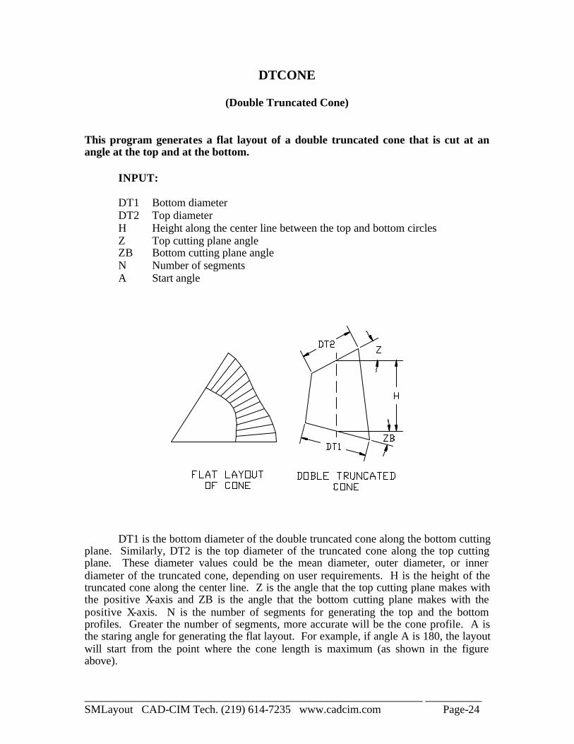
(Double Truncated Cone) This program generates a flat layout of a double truncated cone that is cut at an angle at the top and at the bottom.
INPUT: DT1 Bottom diameter DT2 Top diameter H Height along the center line between the top and bottom circles Z Top cutting plane angle ZB Bottom cutting plane angle N Number of segments A Start angle
DT1 is the bottom diameter of the double truncated cone along the bottom cutting plane. Similarly, DT2 is the top diameter of the truncated cone along the top cutting plane. These diameter values could be the mean diameter, outer diameter, or inner diameter of the truncated cone, depending on user requirements. H is the height of the truncated cone along the center line. Z is the angle that the top cutting plane makes with the positive X-axis and ZB is the angle that the bottom cutting plane makes with the positive X-axis. N is the number of segments for generating the top and the bottom profiles. Greater the number of segments, more accurate will be the cone profile. A is the staring angle for generating the flat layout. For example, if angle A is 180, the layout will start from the point where the cone length is maximum (as shown in the figure above).
____________________________________________________________ __________ SMLayout CAD-CIM Tech. (219) 614-7235 www.cadcim.com Page-25
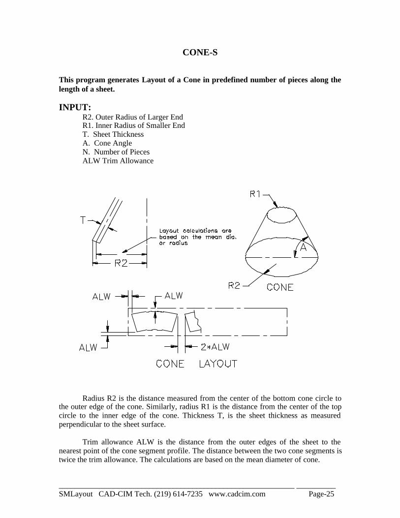
CONE-S This program generates Layout of a Cone in predefined number of pieces along the length of a sheet. INPUT: R2. Outer Radius of Larger End R1. Inner Radius of Smaller End T. Sheet Thickness A. Cone Angle N. Number of Pieces ALW Trim Allowance
Radius R2 is the distance measured from the center of the bottom cone circle to the outer edge of the cone. Similarly, radius R1 is the distance from the center of the top circle to the inner edge of the cone. Thickness T, is the sheet thickness as measured perpendicular to the sheet surface. Trim allowance ALW is the distance from the outer edges of the sheet to the nearest point of the cone segment profile. The distance between the two cone segments is twice the trim allowance. The calculations are based on the mean diameter of cone.
____________________________________________________________ __________ SMLayout CAD-CIM Tech. (219) 614-7235 www.cadcim.com Page-26
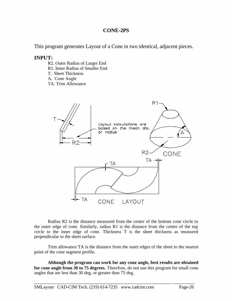
CONE-2PS This program generates Layout of a Cone in two identical, adjacent pieces. INPUT: R2. Outer Radius of Larger End R1. Inner Radius of Smaller End T. Sheet Thickness A. Cone Angle TA. Trim Allowance
Radius R2 is the distance measured from the center of the bottom cone circle to the outer edge of cone. Similarly, radius R1 is the distance from the center of the top circle to the inner edge of cone. Thickness T is the sheet thickness as measured perpendicular to the sheet surface. Trim allowance TA is the distance from the outer edges of the sheet to the nearest point of the cone segment profile. Although the program can work for any cone angle, best results are obtained for cone angle from 30 to 75 degrees. Therefore, do not use this program for small cone angles that are less than 30 deg. or greater than 75 deg.
____________________________________________________________ __________ SMLayout CAD-CIM Tech. (219) 614-7235 www.cadcim.com Page-27
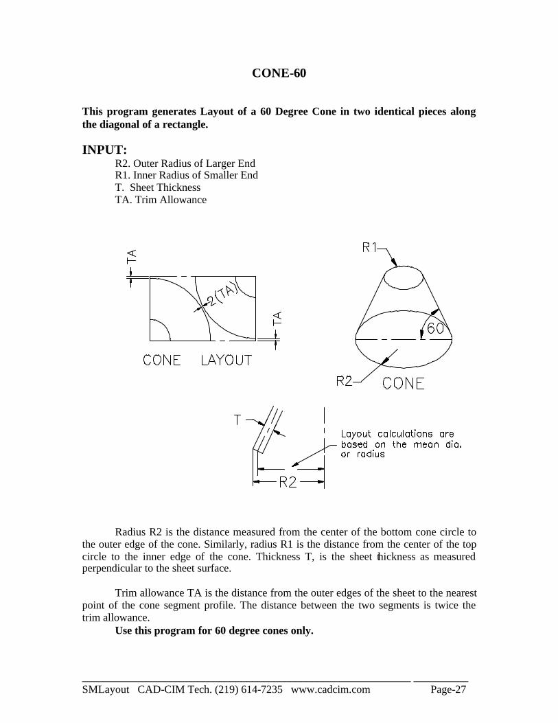
CONE-60 This program generates Layout of a 60 Degree Cone in two identical pieces along the diagonal of a rectangle. INPUT: R2. Outer Radius of Larger End R1. Inner Radius of Smaller End T. Sheet Thickness TA. Trim Allowance
Radius R2 is the distance measured from the center of the bottom cone circle to the outer edge of the cone. Similarly, radius R1 is the distance from the center of the top circle to the inner edge of the cone. Thickness T, is the sheet thickness as measured perpendicular to the sheet surface. Trim allowance TA is the distance from the outer edges of the sheet to the nearest point of the cone segment profile. The distance between the two segments is twice the trim allowance. Use this program for 60 degree cones only.
____________________________________________________________ __________ SMLayout CAD-CIM Tech. (219) 614-7235 www.cadcim.com Page-28
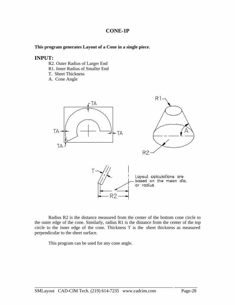
CONE-1P This program generates Layout of a Cone in a single piece. INPUT: R2. Outer Radius of Larger End R1. Inner Radius of Smaller End T. Sheet Thickness A. Cone Angle
Radius R2 is the distance measured from the center of the bottom cone circle to the outer edge of the cone. Similarly, radius R1 is the distance from the center of the top circle to the inner edge of the cone. Thickness T is the sheet thickness as measured perpendicular to the sheet surface. This program can be used for any cone angle.
____________________________________________________________ __________ SMLayout CAD-CIM Tech. (219) 614-7235 www.cadcim.com Page-29
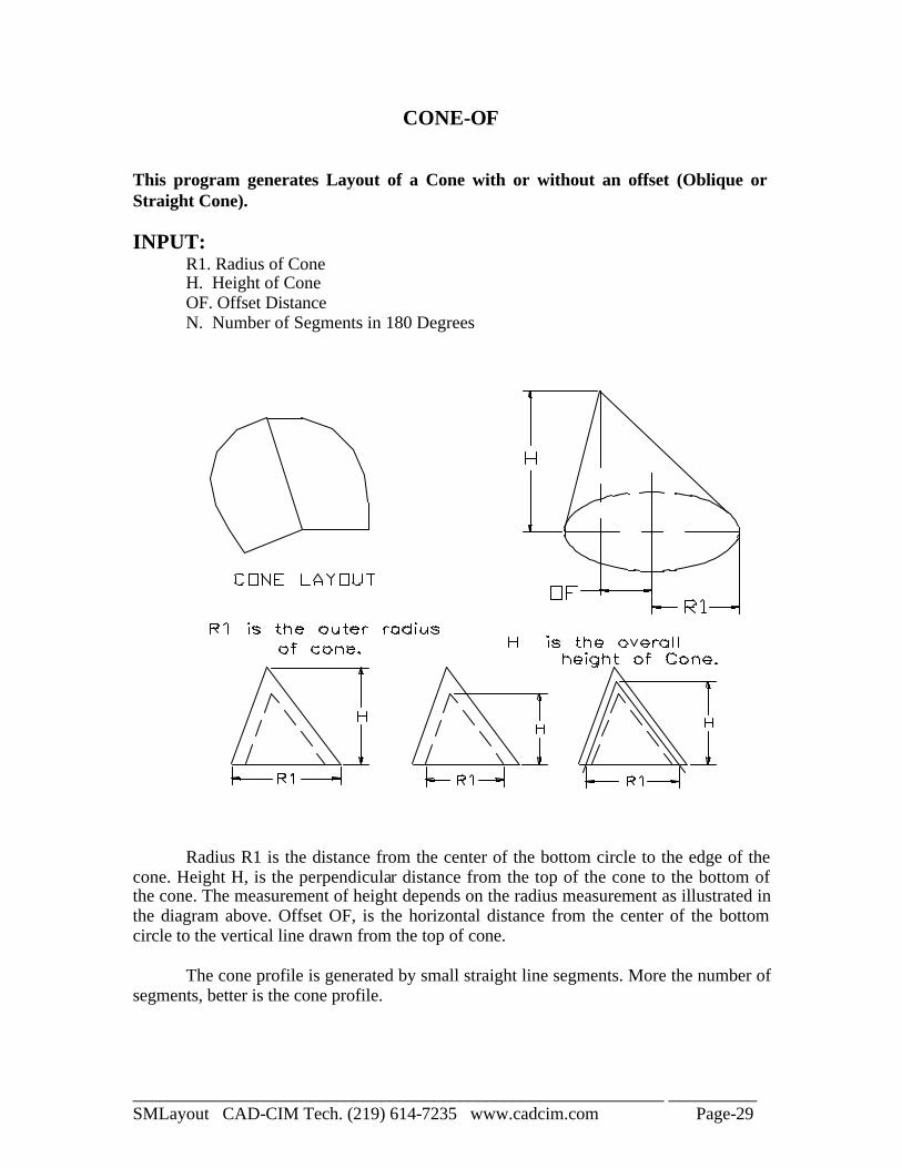
CONE-OF This program generates Layout of a Cone with or without an offset (Oblique or Straight Cone). INPUT: R1. Radius of Cone H. Height of Cone OF. Offset Distance N. Number of Segments in 180 Degrees
Radius R1 is the distance from the center of the bottom circle to the edge of the cone. Height H, is the perpendicular distance from the top of the cone to the bottom of the cone. The measurement of height depends on the radius measurement as illustrated in the diagram above. Offset OF, is the horizontal distance from the center of the bottom circle to the vertical line drawn from the top of cone. The cone profile is generated by small straight line segments. More the number of segments, better is the cone profile.

____________________________________________________________ __________ SMLayout CAD-CIM Tech. (219) 614-7235 www.cadcim.com Page-30
CONE-2OF This program generates Layout of a Cone with or without offset (Oblique Cone), when the top of the cone is cut. INPUT: R1. Radius of Top Cone Circle R2. Radius of Bottom Cone Circle H. Height of Cone OF2.Offset Distance between Circle Centers N. Number of Segments in 180 Degrees
Radius R2 is the distance from the center of the bottom circle to the edge of cone. Similarly, radius R1 is the distance from the center of the top circle to the edge of cone. Height H is the perpendicular distance from the top of the cone to the bottom of the cone. Offset OF2 is the horizontal distance from the center of the bottom circle to the vertical line drawn from the center of the top cone circle. The cone profile is generated by small straight line segments. More the number of segments, better is the cone profile.
____________________________________________________________ __________ SMLayout CAD-CIM Tech. (219) 614-7235 www.cadcim.com Page-31
CONCYLP
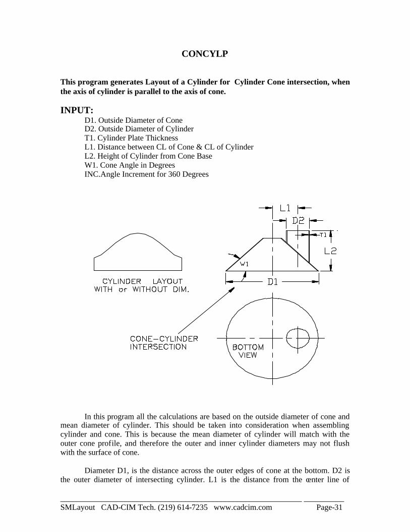
This program generates Layout of a Cylinder for Cylinder Cone intersection, when the axis of cylinder is parallel to the axis of cone. INPUT: D1. Outside Diameter of Cone D2. Outside Diameter of Cylinder T1. Cylinder Plate Thickness L1. Distance between CL of Cone & CL of Cylinder L2. Height of Cylinder from Cone Base W1. Cone Angle in Degrees INC.Angle Increment for 360 Degrees
In this program all the calculations are based on the outside diameter of cone and mean diameter of cylinder. This should be taken into consideration when assembling cylinder and cone. This is because the mean diameter of cylinder will match with the outer cone profile, and therefore the outer and inner cylinder diameters may not flush with the surface of cone. Diameter D1, is the distance across the outer edges of cone at the bottom. D2 is the outer diameter of intersecting cylinder. L1 is the distance from the center line of

____________________________________________________________ __________ SMLayout CAD-CIM Tech. (219) 614-7235 www.cadcim.com Page-32
cylinder to center line of cone. L2 is the distance from the bottom of cone to the end of the cylinder, or it is the projected height of cylinder from the bottom of cone. The cylinder profile consists of straight line segments, and the number of line segments is determined by the increment angle "INC". For example, if the increment angle is 15 degrees there will be (360/15 = 24) 24 segments in the cylinder profile. More the number of segments, smoother the cylinder profile.
____________________________________________________________ __________ SMLayout CAD-CIM Tech. (219) 614-7235 www.cadcim.com Page-33
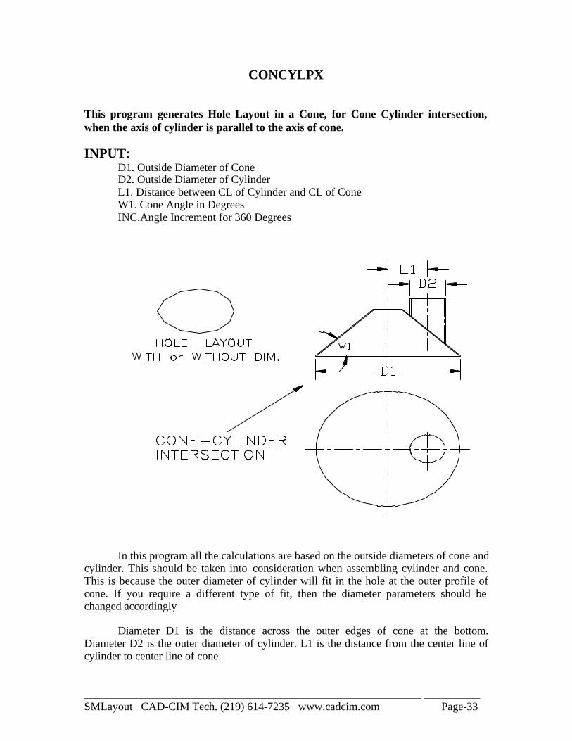
CONCYLPX This program generates Hole Layout in a Cone, for Cone Cylinder intersection, when the axis of cylinder is parallel to the axis of cone. INPUT: D1. Outside Diameter of Cone D2. Outside Diameter of Cylinder L1. Distance between CL of Cylinder and CL of Cone W1. Cone Angle in Degrees INC.Angle Increment for 360 Degrees
In this program all the calculations are based on the outside diameters of cone and cylinder. This should be taken into consideration when assembling cylinder and cone. This is because the outer diameter of cylinder will fit in the hole at the outer profile of cone. If you require a different type of fit, then the diameter parameters should be changed accordingly Diameter D1 is the distance across the outer edges of cone at the bottom. Diameter D2 is the outer diameter of cylinder. L1 is the distance from the center line of cylinder to center line of cone.

____________________________________________________________ __________ SMLayout CAD-CIM Tech. (219) 614-7235 www.cadcim.com Page-34
The hole profile consists of straight line segments, and the number of line segments is determined by the increment angle "INC". For example, if the increment angle is 15 degrees, there will be (360/15 = 24) 24 segments in the hole profile. More the number of segments, smoother and more accurate the hole profile.
____________________________________________________________ __________ SMLayout CAD-CIM Tech. (219) 614-7235 www.cadcim.com Page-35
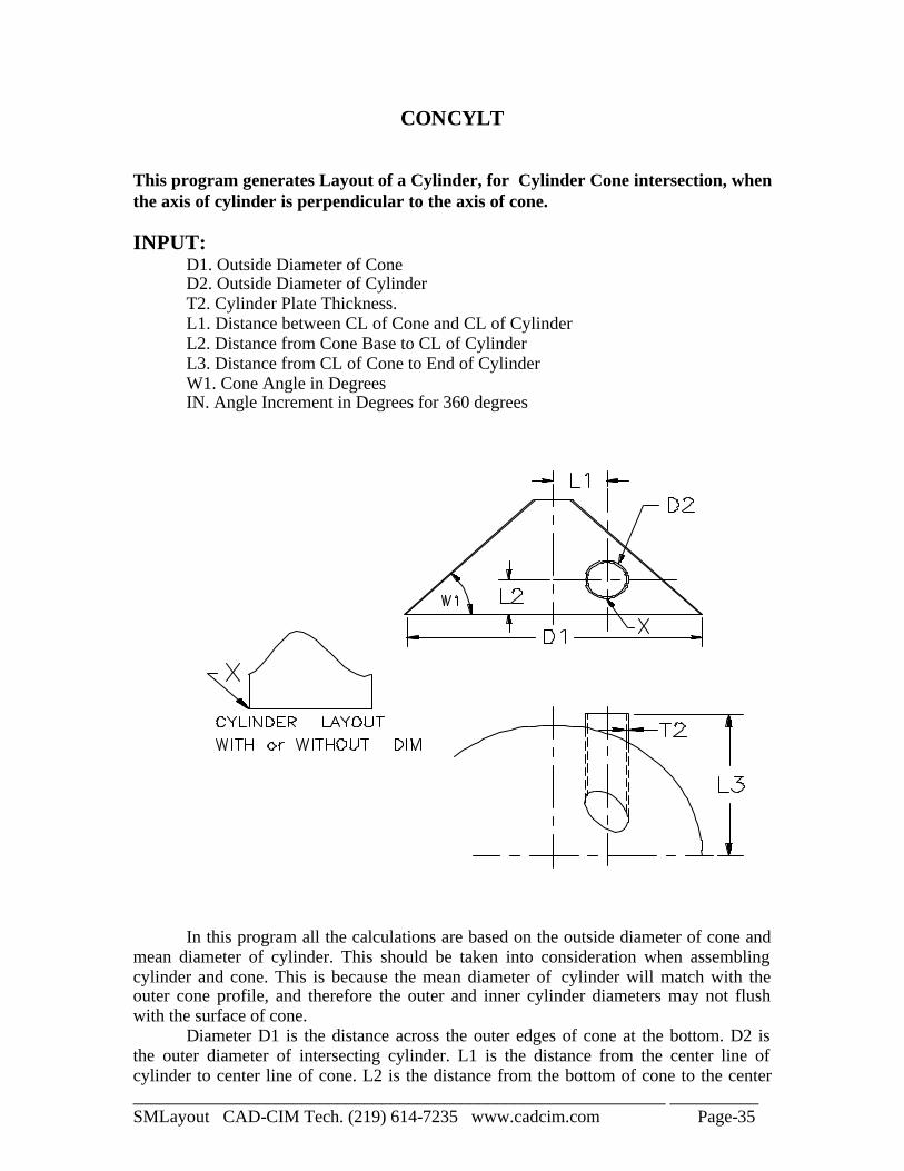
CONCYLT This program generates Layout of a Cylinder, for Cylinder Cone intersection, when the axis of cylinder is perpendicular to the axis of cone. INPUT: D1. Outside Diameter of Cone D2. Outside Diameter of Cylinder T2. Cylinder Plate Thickness. L1. Distance between CL of Cone and CL of Cylinder L2. Distance from Cone Base to CL of Cylinder L3. Distance from CL of Cone to End of Cylinder W1. Cone Angle in Degrees IN. Angle Increment in Degrees for 360 degrees
In this program all the calculations are based on the outside diameter of cone and mean diameter of cylinder. This should be taken into consideration when assembling cylinder and cone. This is because the mean diameter of cylinder will match with the outer cone profile, and therefore the outer and inner cylinder diameters may not flush with the surface of cone. Diameter D1 is the distance across the outer edges of cone at the bottom. D2 is the outer diameter of intersecting cylinder. L1 is the distance from the center line of cylinder to center line of cone. L2 is the distance from the bottom of cone to the center

____________________________________________________________ __________ SMLayout CAD-CIM Tech. (219) 614-7235 www.cadcim.com Page-36
line of cylinder. L3 is the distance from the center line of cone to the end of cylinder, or it is the projected height of cylinder from the center line of cone. The cylinder profile consists of straight line segments, and the number of line segments is determined by the increment angle "INC". For example, if the increment angle is 15 degrees, there will be (360/15 = 24) 24 segments in the cylinder profile. More the number of segments, smoother the cylinder profile.
____________________________________________________________ __________ SMLayout CAD-CIM Tech. (219) 614-7235 www.cadcim.com Page-37
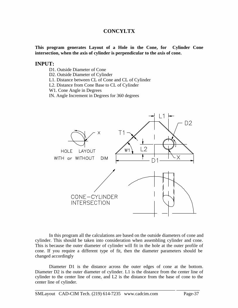
CONCYLTX This program generates Layout of a Hole in the Cone, for Cylinder Cone intersection, when the axis of cylinder is perpendicular to the axis of cone. INPUT: D1. Outside Diameter of Cone D2. Outside Diameter of Cylinder L1. Distance between CL of Cone and CL of Cylinder L2. Distance from Cone Base to CL of Cylinder W1. Cone Angle in Degrees IN. Angle Increment in Degrees for 360 degrees
In this program all the calculations are based on the outside diameters of cone and cylinder. This should be taken into consideration when assembling cylinder and cone. This is because the outer diameter of cylinder will fit in the hole at the outer profile of cone. If you require a different type of fit, then the diameter parameters should be changed accordingly Diameter D1 is the distance across the outer edges of cone at the bottom. Diameter D2 is the outer diameter of cylinder. L1 is the distance from the center line of cylinder to the center line of cone, and L2 is the distance from the base of cone to the center line of cylinder.
____________________________________________________________ __________ SMLayout CAD-CIM Tech. (219) 614-7235 www.cadcim.com Page-38
The hole profile consists of straight line segments, and the number of line segments is determined by the increment angle "INC". For example, if the increment angle is 15 degrees, there will be (360/15 = 24) 24 segments in the hole profile. More the number of segments, smoother and more accurate the hole profile. NOTE:- Before cutting the hole profile in the material, it is very important to find the correct orientation of the profile on the cone surface. It will be better to cut the cylinder first and then cut a hole in the cone.
____________________________________________________________ __________ SMLayout CAD-CIM Tech. (219) 614-7235 www.cadcim.com Page-39
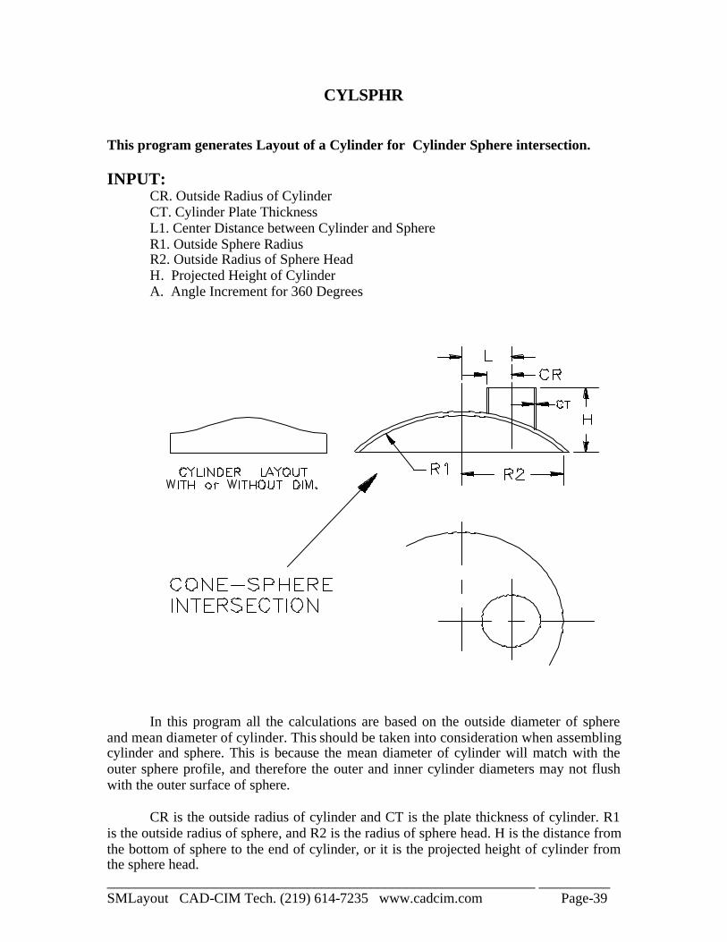
CYLSPHR This program generates Layout of a Cylinder for Cylinder Sphere intersection. INPUT: CR. Outside Radius of Cylinder CT. Cylinder Plate Thickness L1. Center Distance between Cylinder and Sphere R1. Outside Sphere Radius R2. Outside Radius of Sphere Head H. Projected Height of Cylinder A. Angle Increment for 360 Degrees
In this program all the calculations are based on the outside diameter of sphere and mean diameter of cylinder. This should be taken into consideration when assembling cylinder and sphere. This is because the mean diameter of cylinder will match with the outer sphere profile, and therefore the outer and inner cylinder diameters may not flush with the outer surface of sphere. CR is the outside radius of cylinder and CT is the plate thickness of cylinder. R1 is the outside radius of sphere, and R2 is the radius of sphere head. H is the distance from the bottom of sphere to the end of cylinder, or it is the projected height of cylinder from the sphere head.

____________________________________________________________ __________ SMLayout CAD-CIM Tech. (219) 614-7235 www.cadcim.com Page-40
The cylinder profile consists of straight line segments, and the number of line segments is determined by the increment angle "A". For example, if the increment angle is 15 degrees, there will be (360/15 = 24) 24 segments in the cylinder profile. More the number of segments, smoother and more accurate the cylinder profile.
____________________________________________________________ __________ SMLayout CAD-CIM Tech. (219) 614-7235 www.cadcim.com Page-41
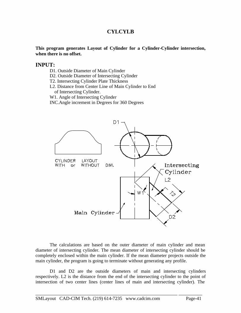
CYLCYLB This program generates Layout of Cylinder for a Cylinder-Cylinder intersection, when there is no offset. INPUT: D1. Outside Diameter of Main Cylinder D2. Outside Diameter of Intersecting Cylinder T2. Intersecting Cylinder Plate Thickness L2. Distance from Center Line of Main Cylinder to End of Intersecting Cylinder. W1. Angle of Intersecting Cylinder INC.Angle increment in Degrees for 360 Degrees
The calculations are based on the outer diameter of main cylinder and mean diameter of intersecting cylinder. The mean diameter of intersecting cylinder should be completely enclosed within the main cylinder. If the mean diameter projects outside the main cylinder, the program is going to terminate without generating any profile. D1 and D2 are the outside diameters of main and intersecting cylinders respectively. L2 is the distance from the end of the intersecting cylinder to the point of intersection of two center lines (center lines of main and intersecting cylinder). The

____________________________________________________________ __________ SMLayout CAD-CIM Tech. (219) 614-7235 www.cadcim.com Page-42
distance is to be measures along the center line of the intersecting cylinder. W1 is the angle between the center lines of two cylinders. The cylinder profile consists of straight line segments, and the number of line segments is determined by the increment angle "INC". For example, if the increment angle is 15 degrees, there will be (360/15 = 24) 24 segments in the cylinder profile. More the number of segments, smoother and more accurate the cylinder profile.
____________________________________________________________ __________ SMLayout CAD-CIM Tech. (219) 614-7235 www.cadcim.com Page-43
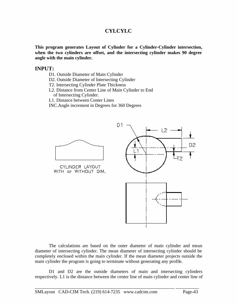
CYLCYLC This program generates Layout of Cylinder for a Cylinder-Cylinder intersection, when the two cylinders are offset, and the intersecting cylinder makes 90 degree angle with the main cylinder. INPUT: D1. Outside Diameter of Main Cylinder D2. Outside Diameter of Intersecting Cylinder T2. Intersecting Cylinder Plate Thickness L2. Distance from Center Line of Main Cylinder to End of Intersecting Cylinder. L1. Distance between Center Lines INC.Angle increment in Degrees for 360 Degrees
The calculations are based on the outer diameter of main cylinder and mean diameter of intersecting cylinder. The mean diameter of intersecting cylinder should be completely enclosed within the main cylinder. If the mean diameter projects outside the main cylinder the program is going to terminate without generating any profile. D1 and D2 are the outside diameters of main and intersecting cylinders respectively. L1 is the distance between the center line of main cylinder and center line of

____________________________________________________________ __________ SMLayout CAD-CIM Tech. (219) 614-7235 www.cadcim.com Page-44
intersecting cylinder (Offset distance between two cylinders). L2 is the distance from the end of the intersecting cylinder to the point of intersection of two center lines (center lines of main and intersecting cylinder). The distance is to be measured along the center line of the intersecting cylinder. The cylinder profile consists of straight line segments, and the number of line segments is determined by the increment angle "INC". For example, if the increment angle is 15 degrees, there will be (360/15 = 24) 24 segments in the cylinder profile. More the number of segments, smoother and more accurate the cylinder profile.
____________________________________________________________ __________ SMLayout CAD-CIM Tech. (219) 614-7235 www.cadcim.com Page-45
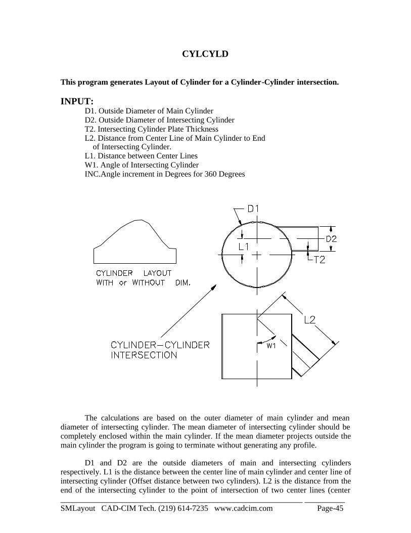
CYLCYLD This program generates Layout of Cylinder for a Cylinder-Cylinder intersection. INPUT: D1. Outside Diameter of Main Cylinder D2. Outside Diameter of Intersecting Cylinder T2. Intersecting Cylinder Plate Thickness L2. Distance from Center Line of Main Cylinder to End of Intersecting Cylinder. L1. Distance between Center Lines W1. Angle of Intersecting Cylinder INC.Angle increment in Degrees for 360 Degrees
The calculations are based on the outer diameter of main cylinder and mean diameter of intersecting cylinder. The mean diameter of intersecting cylinder should be completely enclosed within the main cylinder. If the mean diameter projects outside the main cylinder the program is going to terminate without generating any profile. D1 and D2 are the outside diameters of main and intersecting cylinders respectively. L1 is the distance between the center line of main cylinder and center line of intersecting cylinder (Offset distance between two cylinders). L2 is the distance from the end of the intersecting cylinder to the point of intersection of two center lines (center

____________________________________________________________ __________ SMLayout CAD-CIM Tech. (219) 614-7235 www.cadcim.com Page-46
lines of main and intersecting cylinder). The distance is to be measures along the center line of the intersecting cylinder. W1 is the angle between the center lines of two cylinders. The cylinder profile consists of straight line segments, and the number of line segments is determined by the increment angle "INC". For example, if the increment angle is 15 degrees, there will be (360/15 = 24) 24 segments in the cylinder profile. More the number of segments, smoother and more accurate the cylinder profile.
____________________________________________________________ __________ SMLayout CAD-CIM Tech. (219) 614-7235 www.cadcim.com Page-47
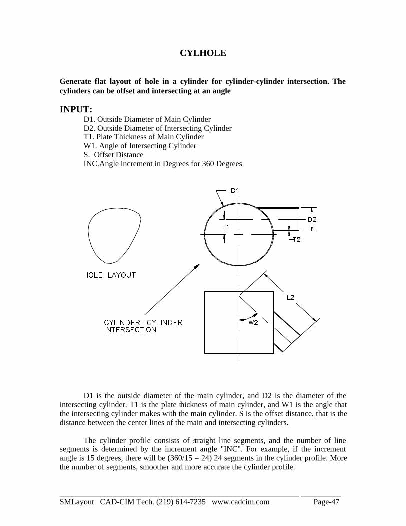
CYLHOLE
Generate flat layout of hole in a cylinder for cylinder-cylinder intersection. The cylinders can be offset and intersecting at an angle INPUT: D1. Outside Diameter of Main Cylinder D2. Outside Diameter of Intersecting Cylinder T1. Plate Thickness of Main Cylinder W1. Angle of Intersecting Cylinder S. Offset Distance INC.Angle increment in Degrees for 360 Degrees
D1 is the outside diameter of the main cylinder, and D2 is the diameter of the intersecting cylinder. T1 is the plate thickness of main cylinder, and W1 is the angle that the intersecting cylinder makes with the main cylinder. S is the offset distance, that is the distance between the center lines of the main and intersecting cylinders. The cylinder profile consists of straight line segments, and the number of line segments is determined by the increment angle "INC". For example, if the increment angle is 15 degrees, there will be (360/15 = 24) 24 segments in the cylinder profile. More the number of segments, smoother and more accurate the cylinder profile.
____________________________________________________________ __________ SMLayout CAD-CIM Tech. (219) 614-7235 www.cadcim.com Page-48
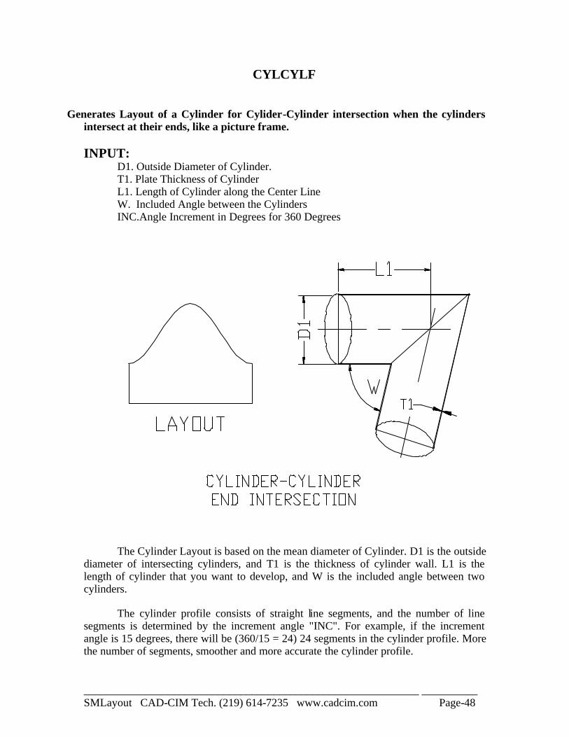
CYLCYLF
Generates Layout of a Cylinder for Cylider-Cylinder intersection when the cylinders
intersect at their ends, like a picture frame. INPUT:
D1. Outside Diameter of Cylinder. T1. Plate Thickness of Cylinder L1. Length of Cylinder along the Center Line W. Included Angle between the Cylinders INC.Angle Increment in Degrees for 360 Degrees
The Cylinder Layout is based on the mean diameter of Cylinder. D1 is the outside diameter of intersecting cylinders, and T1 is the thickness of cylinder wall. L1 is the length of cylinder that you want to develop, and W is the included angle between two cylinders. The cylinder profile consists of straight line segments, and the number of line segments is determined by the increment angle "INC". For example, if the increment angle is 15 degrees, there will be (360/15 = 24) 24 segments in the cylinder profile. More the number of segments, smoother and more accurate the cylinder profile.
____________________________________________________________ __________ SMLayout CAD-CIM Tech. (219) 614-7235 www.cadcim.com Page-49
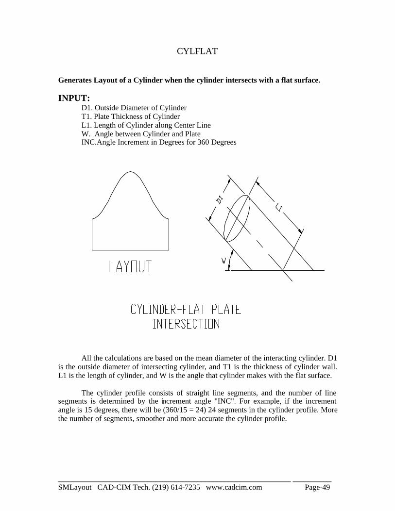
CYLFLAT
Generates Layout of a Cylinder when the cylinder intersects with a flat surface. INPUT:
D1. Outside Diameter of Cylinder T1. Plate Thickness of Cylinder L1. Length of Cylinder along Center Line W. Angle between Cylinder and Plate INC.Angle Increment in Degrees for 360 Degrees
All the calculations are based on the mean diameter of the interacting cylinder. D1 is the outside diameter of intersecting cylinder, and T1 is the thickness of cylinder wall. L1 is the length of cylinder, and W is the angle that cylinder makes with the flat surface. The cylinder profile consists of straight line segments, and the number of line segments is determined by the increment angle "INC". For example, if the increment angle is 15 degrees, there will be (360/15 = 24) 24 segments in the cylinder profile. More the number of segments, smoother and more accurate the cylinder profile.
____________________________________________________________ __________ SMLayout CAD-CIM Tech. (219) 614-7235 www.cadcim.com Page-50
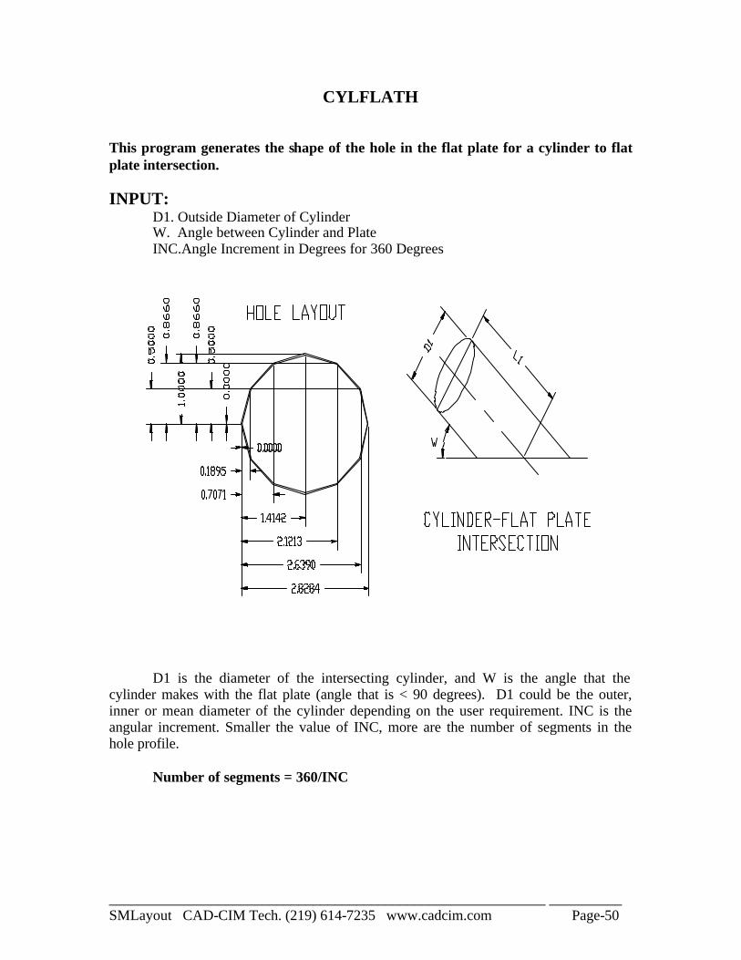
CYLFLATH This program generates the shape of the hole in the flat plate for a cylinder to flat plate intersection. INPUT:
D1. Outside Diameter of Cylinder W. Angle between Cylinder and Plate INC.Angle Increment in Degrees for 360 Degrees
D1 is the diameter of the intersecting cylinder, and W is the angle that the cylinder makes with the flat plate (angle that is < 90 degrees). D1 could be the outer, inner or mean diameter of the cylinder depending on the user requirement. INC is the angular increment. Smaller the value of INC, more are the number of segments in the hole profile. Number of segments = 360/INC
____________________________________________________________ __________ SMLayout CAD-CIM Tech. (219) 614-7235 www.cadcim.com Page-51
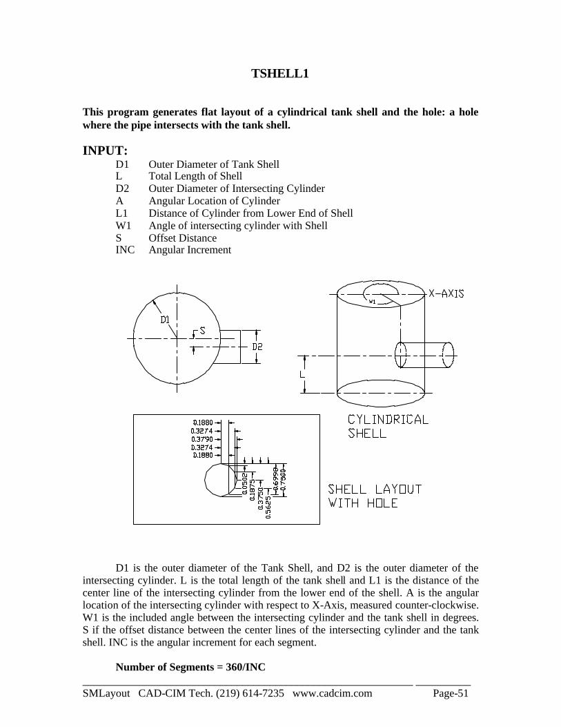
TSHELL1 This program generates flat layout of a cylindrical tank shell and the hole: a hole where the pipe intersects with the tank shell. INPUT:
D1 Outer Diameter of Tank Shell L Total Length of Shell D2 Outer Diameter of Intersecting Cylinder A Angular Location of Cylinder L1 Distance of Cylinder from Lower End of Shell W1 Angle of intersecting cylinder with Shell S Offset Distance INC Angular Increment
D1 is the outer diameter of the Tank Shell, and D2 is the outer diameter of the intersecting cylinder. L is the total length of the tank shell and L1 is the distance of the center line of the intersecting cylinder from the lower end of the shell. A is the angular location of the intersecting cylinder with respect to X-Axis, measured counter-clockwise. W1 is the included angle between the intersecting cylinder and the tank shell in degrees. S if the offset distance between the center lines of the intersecting cylinder and the tank shell. INC is the angular increment for each segment. Number of Segments = 360/INC
____________________________________________________________ __________ SMLayout CAD-CIM Tech. (219) 614-7235 www.cadcim.com Page-52
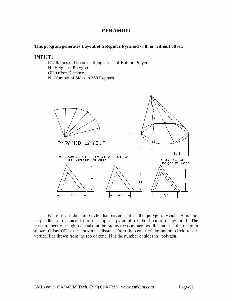
PYRAMID1 This program generates Layout of a Regular Pyramid with or without offset. INPUT: R1. Radius of Circumscribing Circle of Bottom Polygon H. Height of Polygon OF. Offset Distance N. Number of Sides in 360 Degrees
R1 is the radius of circle that circumscribes the polygon. Height H is the perpendicular distance from the top of pyramid to the bottom of pyramid. The measurement of height depends on the radius measurement as illustrated in the diagram above. Offset OF is the horizontal distance from the center of the bottom circle to the vertical line drawn from the top of cone. N is the number of sides in polygon.
____________________________________________________________ __________ SMLayout CAD-CIM Tech. (219) 614-7235 www.cadcim.com Page-53
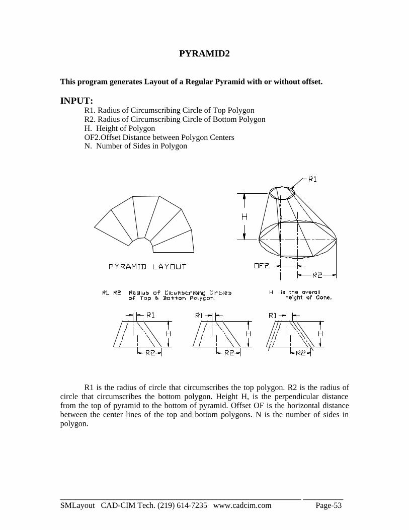
PYRAMID2 This program generates Layout of a Regular Pyramid with or without offset. INPUT: R1. Radius of Circumscribing Circle of Top Polygon R2. Radius of Circumscribing Circle of Bottom Polygon H. Height of Polygon OF2.Offset Distance between Polygon Centers N. Number of Sides in Polygon
R1 is the radius of circle that circumscribes the top polygon. R2 is the radius of circle that circumscribes the bottom polygon. Height H, is the perpendicular distance from the top of pyramid to the bottom of pyramid. Offset OF is the horizontal distance between the center lines of the top and bottom polygons. N is the number of sides in polygon.
____________________________________________________________ __________ SMLayout CAD-CIM Tech. (219) 614-7235 www.cadcim.com Page-54
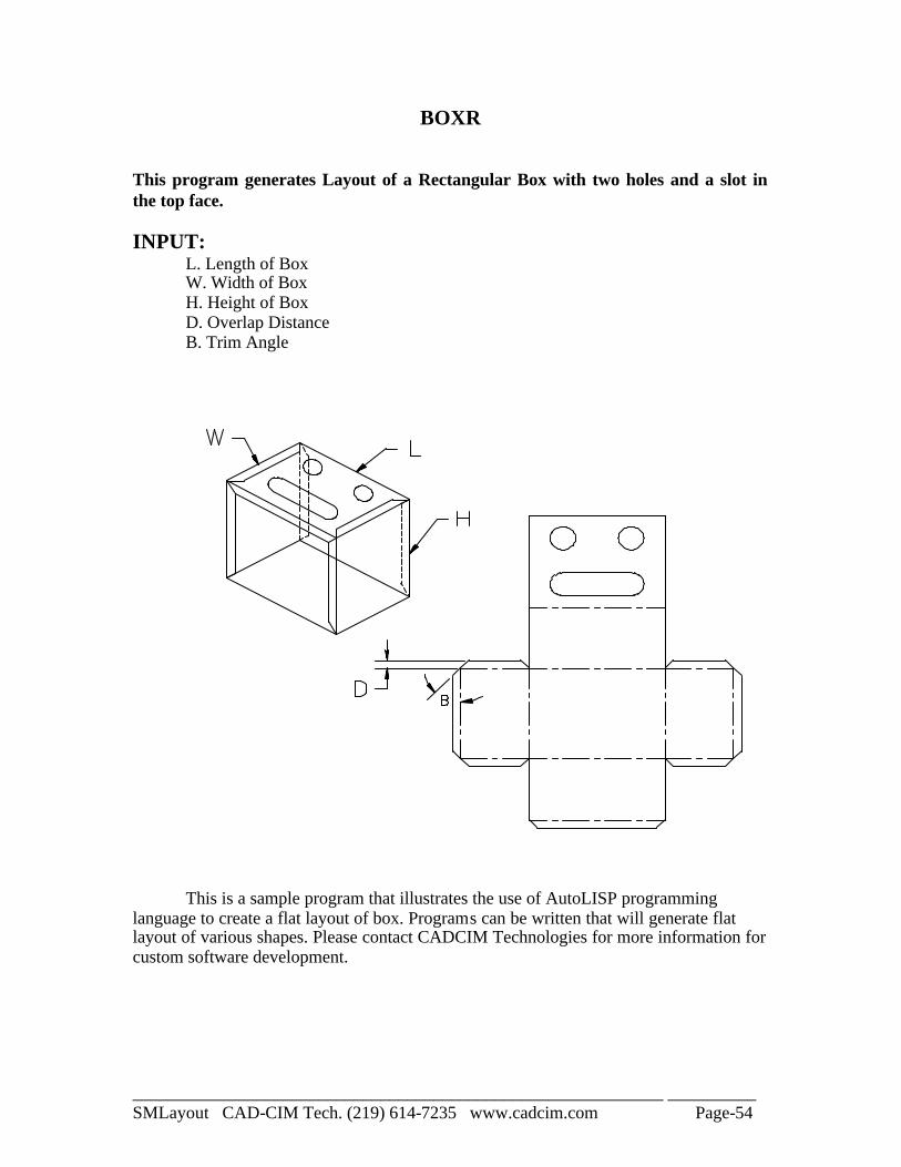
BOXR This program generates Layout of a Rectangular Box with two holes and a slot in the top face. INPUT: L. Length of Box W. Width of Box H. Height of Box D. Overlap Distance B. Trim Angle
This is a sample program that illustrates the use of AutoLISP programming language to create a flat layout of box. Programs can be written that will generate flat layout of various shapes. Please contact CADCIM Technologies for more information for custom software development.
____________________________________________________________ __________ SMLayout CAD-CIM Tech. (219) 614-7235 www.cadcim.com Page-55
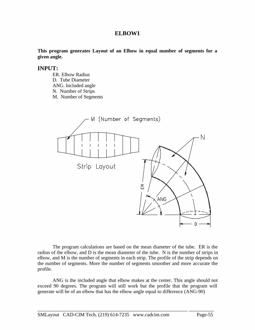
ELBOW1 This program generates Layout of an Elbow in equal number of segments for a given angle. INPUT: ER. Elbow Radius D. Tube Diameter ANG. Included angle N. Number of Strips M. Number of Segments
The program calculations are based on the mean diameter of the tube. ER is the radius of the elbow, and D is the mean diameter of the tube. N is the number of strips in elbow, and M is the number of segments in each strip. The profile of the strip depends on the number of segments. More the number of segments smoother and more accurate the profile. ANG is the included angle that elbow makes at the center. This angle should not exceed 90 degrees. The program will still work but the profile that the program will generate will be of an elbow that has the elbow angle equal to difference (ANG-90)
____________________________________________________________ __________ SMLayout CAD-CIM Tech. (219) 614-7235 www.cadcim.com Page-56
TELBOW
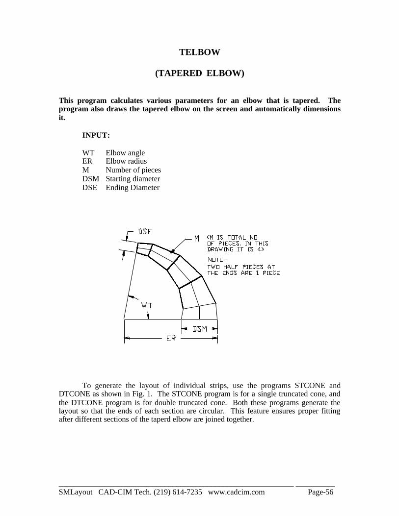
(TAPERED ELBOW) This program calculates various parameters for an elbow that is tapered. The program also draws the tapered elbow on the screen and automatically dimensions it.
INPUT: WT Elbow angle ER Elbow radius M Number of pieces DSM Starting diameter DSE Ending Diameter
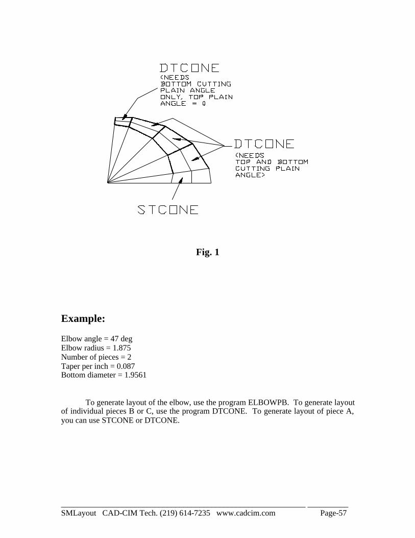
To generate the layout of individual strips, use the programs STCONE and DTCONE as shown in Fig. 1. The STCONE program is for a single truncated cone, and the DTCONE program is for double truncated cone. Both these programs generate the layout so that the ends of each section are circular. This feature ensures proper fitting after different sections of the taperd elbow are joined together.
____________________________________________________________ __________ SMLayout CAD-CIM Tech. (219) 614-7235 www.cadcim.com Page-57
Fig. 1
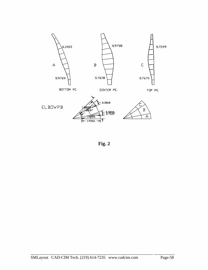
Example: Elbow angle = 47 deg Elbow radius = 1.875 Number of pieces = 2 Taper per inch = 0.087 Bottom diameter = 1.9561 To generate layout of the elbow, use the program ELBOWPB. To generate layout of individual pieces B or C, use the program DTCONE. To generate layout of piece A, you can use STCONE or DTCONE.
____________________________________________________________ __________ SMLayout CAD-CIM Tech. (219) 614-7235 www.cadcim.com Page-58
Fig. 2
____________________________________________________________ __________ SMLayout CAD-CIM Tech. (219) 614-7235 www.cadcim.com Page-59
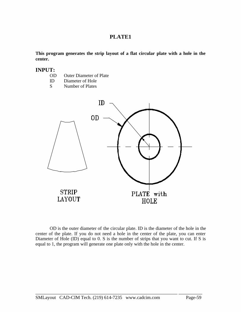
PLATE1
This program generates the strip layout of a flat circular plate with a hole in the center. INPUT:
OD Outer Diameter of Plate ID Diameter of Hole S Number of Plates
OD is the outer diameter of the circular plate. ID is the diameter of the hole in the center of the plate. If you do not need a hole in the center of the plate, you can enter Diameter of Hole (ID) equal to 0. S is the number of strips that you want to cut. If S is equal to 1, the program will generate one plate only with the hole in the center.
____________________________________________________________ __________ SMLayout CAD-CIM Tech. (219) 614-7235 www.cadcim.com Page-60
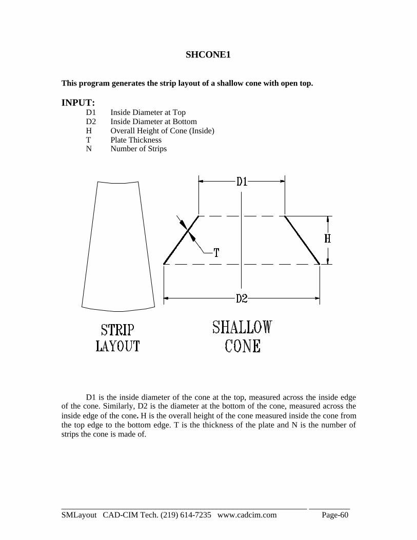
SHCONE1 This program generates the strip layout of a shallow cone with open top. INPUT:
D1 Inside Diameter at Top D2 Inside Diameter at Bottom H Overall Height of Cone (Inside) T Plate Thickness N Number of Strips
D1 is the inside diameter of the cone at the top, measured across the inside edge of the cone. Similarly, D2 is the diameter at the bottom of the cone, measured across the inside edge of the cone. H is the overall height of the cone measured inside the cone from the top edge to the bottom edge. T is the thickness of the plate and N is the number of strips the cone is made of.
____________________________________________________________ __________ SMLayout CAD-CIM Tech. (219) 614-7235 www.cadcim.com Page-61
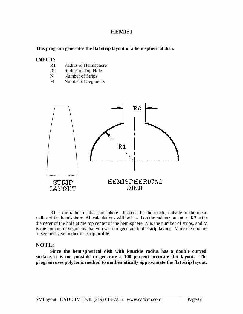
HEMIS1 This program generates the flat strip layout of a hemispherical dish. INPUT:
R1 Radius of Hemisphere R2 Radius of Top Hole N Number of Strips M Number of Segments
R1 is the radius of the hemisphere. It could be the inside, outside or the mean radius of the hemisphere. All calculations will be based on the radius you enter. R2 is the diameter of the hole at the top center of the hemisphere. N is the number of strips, and M is the number of segments that you want to generate in the strip layout. More the number of segments, smoother the strip profile. NOTE: Since the hemispherical dish with knuckle radius has a double curved surface, it is not possible to generate a 100 percent accurate flat layout. The program uses polyconic method to mathematically approximate the flat strip layout.
____________________________________________________________ __________ SMLayout CAD-CIM Tech. (219) 614-7235 www.cadcim.com Page-62
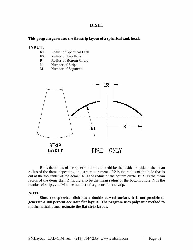
DISH1 This program generates the flat strip layout of a spherical tank head. INPUT:
R1 Radius of Spherical Dish R2 Radius of Top Hole R Radius of Bottom Circle N Number of Strips M Number of Segments
R1 is the radius of the spherical dome. It could be the inside, outside or the mean radius of the dome depending on users requirements. R2 is the radius of the hole that is cut at the top center of the dome. R is the radius of the bottom circle. If R1 is the mean radius of the dome then R should also be the mean radius of the bottom circle. N is the number of strips, and M is the number of segments for the strip. NOTE: Since the spherical dish has a double curved surface, it is not possible to generate a 100 percent accurate flat layout. The program uses polyconic method to mathematically approximate the flat strip layout.
____________________________________________________________ __________ SMLayout CAD-CIM Tech. (219) 614-7235 www.cadcim.com Page-63
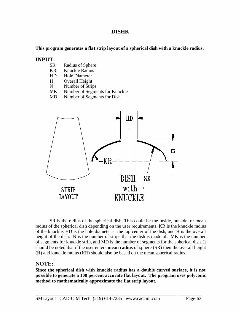
DISHK This program generates a flat strip layout of a spherical dish with a knuckle radius. INPUT:
SR Radius of Sphere KR Knuckle Radius HD Hole Diameter H Overall Height N Number of Strips MK Number of Segments for Knuckle MD Number of Segments for Dish
SR is the radius of the spherical dish. This could be the inside, outside, or mean radius of the spherical dish depending on the user requirements. KR is the knuckle radius of the knuckle. HD is the hole diameter at the top center of the dish, and H is the overall height of the dish. N is the number of strips that the dish is made of. MK is the number of segments for knuckle strip, and MD is the number of segments for the spherical dish. It should be noted that if the user enters mean radius of sphere (SR) then the overall height (H) and knuckle radius (KR) should also be based on the mean spherical radius. NOTE: Since the spherical dish with knuckle radius has a double curved surface, it is not possible to generate a 100 percent accurate flat layout. The program uses polyconic method to mathematically approximate the flat strip layout.

____________________________________________________________ __________ SMLayout CAD-CIM Tech. (219) 614-7235 www.cadcim.com Page-64
Notes

____________________________________________________________ __________ SMLayout CAD-CIM Tech. (219) 614-7235 www.cadcim.com Page-65
Notes

____________________________________________________________ __________ SMLayout CAD-CIM Tech. (219) 614-7235 www.cadcim.com Page-66
Notes