Embed Size (px)
Citation preview

Application Note 012
Sympas Special Functions
Table of Contents Table of Contents .............................................................................................................................................. 1 1. Introduction ............................................................................................................................................. 2 2. Availability and Type of Special Functions ............................................................................................. 2 3. Explanations to the Special Functions.................................................................................................... 3
3.1. Calling a Special Function................................................................................................................... 3 3.1.1. Example (DELTA) ..........................................................................................................................................................3 3.1.2. Example (NANO-C)........................................................................................................................................................3
3.2. Special Function 0: Module Detection................................................................................................. 3 3.3. Special Function 1: Initialize Axis........................................................................................................ 3
3.3.1. Explanations to the Description Block ............................................................................................................................4 3.4. Special Function 4: Conversion of BCD into HEX .............................................................................. 5
3.4.1. Application .....................................................................................................................................................................5 3.4.2. Example (irrespective of the controller) ..........................................................................................................................5 3.4.3. Note...............................................................................................................................................................................6
3.5. Special Function 5: Conversion of HEX into BCD .............................................................................. 6 3.6. Special Function 7: Define Network Address...................................................................................... 6 3.7. Special Functions 10, 11 and 12......................................................................................................... 7
3.7.1. Notes on Special Functions 10, 11 and 12 .....................................................................................................................7 3.7.2. Special Function 10: CAN: Connect ...............................................................................................................................8 3.7.3. Special Function 11: CAN: Send Data............................................................................................................................9 3.7.4. Special Function 12: CAN: Fetch Data .........................................................................................................................10
3.8. Special Function 20: Square Root .................................................................................................... 11 3.9. Special Function 21: Sine ................................................................................................................. 11 3.10. Special Function 22: Cosine.......................................................................................................... 11 3.11. Special Function 23: Tangent........................................................................................................ 11 3.12. Special Function 24: Arc Sine ....................................................................................................... 11 3.13. Special Function 25: Arc Cosine ................................................................................................... 12 3.14. Special Function 26: Arc Tangens................................................................................................. 12 3.15. Special Function 27: Exponential Function („e high“) ................................................................... 13
3.15.1. Note.............................................................................................................................................................................13 3.16. Special Function 28: Natural Logarithm („ln“)................................................................................ 13
3.16.1. Note.............................................................................................................................................................................13 3.17. Special Function 29: Absolute Value............................................................................................. 13 3.18. Special Function 30: MOD............................................................................................................. 13
3.18.1. Example (DELTA) ........................................................................................................................................................14 3.18.2. Note.............................................................................................................................................................................14
3.19. Special Function 40: Multimaster Token Passing ......................................................................... 14 3.19.1. Initializing the Net1 Interface ........................................................................................................................................14 3.19.2. Initializing the Net2 Interface ........................................................................................................................................15 3.19.3. Programming ...............................................................................................................................................................15 3.19.4. Master-Master Operation / Multimaster Mode...............................................................................................................15
3.20. Special Function 252: Determine Checksum ................................................................................ 16
Jetter AG Gräterstrasse 2 D-71642 Ludwigsburg Germany Phone - Switchboard: +7141 2550-0 Phone - Sales: +7141 2550-530 Phone – Technical Hotline: +7141 2550-444
All rights reserved. Jetter AG reserves the right to make alterations to its products in the interest of technical progress. These alterations need not be documented in every single case. This application note and the information contained herein have been compiled with due diligence. However, Jetter AG assumes no liability for printing or other errors or damages arising from such errors.
Telefax:
+7141 2550-425
E-Mail - Sales: [email protected] E-Mail – Technical Hotline: [email protected]
The brand names and product names used in this document are trademarks or registered trademarks of the respective title owner.
Internet Address: http://www.jetter.de Article #: 60861993 Page 1 of 16January 2002 / Markus Friedrich Edition: 1 APN_012_SympasSpecFunc_e.doc

Application Note 012
Sympas Special Functions
1. Introduction The SYMPAS programming language has a limited instruction set. If more instructions are required, special functions are used.
2. Availability and Type of Special Functions The following special functions of SYMPAS are available on the individual controllers (Table 1):
Special function
Result PASE-E Delta Nano-A and Nano-B
Nano-C PC-PPLC
0 Module detection X
1 Initialization of slaves X X
4 BCD � HEX X X X X X
5 HEX � BCD X X X X X
7 Define network address X
10 CAN: connect X
11 CAN: send data X
12 CAN: fetch data X
20 Square root X X X X
21 Sine X X X X
22 Cosine X X X X
23 Tangent X X X X
24 Arc Sine X X X X
25 Arc Cosine X X X X
26 Arc Tangent X X X X
27 ex X X X X
28 Logarithm nat. X X X X
29 Absolute value X X
30 Modulo X X
40 Multimaster token passing X
252 Determine checksum X X
Table 1 No special functions are available on the micro.
Article #: 60861993 Page 2 of 16January 2002 / Markus Friedrich Edition: 1 APN_012_SympasSpecFunc_e.doc

Application Note 012
Sympas Special Functions
3. Explanations to the Special Functions
3.1. Calling a Special Function The SPECIAL FUNCTION is an integral part of the SYMPAS instruction set. A special function is always called with two parameters: SPECIAL FUNCTION [#NUMBER, p1=PARAMETER1, p2= PARAMETER2] See Table 1 for the NUMBER of the special function available. The first parameter (PARAMETER1) represents the number of the register containing the operand (source register). The second parameter (PARAMETER2) represents the number of the register to which the result of the function is written (destination register).
3.1.1. Example (DELTA) SPECIAL FUNCTION [#21, P1=62208, P2=62209] This function calculates the sine of the number in floating-point register 62208, and stores the result in floating-point register 62209. Basically, it is permitted to use integer registers for the transfer of parameters or for the result. However, this does not make sense due to the value range. The parameters PARAMETER1 and PARAMETER2 can also be specified indirectly for all functions.
3.1.2. Example (NANO-C) SPECIAL FUNCTION [#20, p1=R(100), p2=R(101)]
3.2. Special Function 0: Module Detection Special function 0 is only intended for the PC-PPLC. The PC-PPLC is a controller (NANO-C with improved performance) in the form of a PC expansion board. If the PC where the PC-PPLC is located has already been booted without voltage being applied to the plant and thus to the modules, then it must be possible to detect the connected modules without having to restart the PC. Special function 0 is used for this purpose. Any value can be used as parameter since these values are ignored anyway. The simplest case of special function 0 looks as follows: SPECIAL FUNCTION [#0, p1=0, p2=0] Special function 0 is only issued once, i.e. at the beginning of the program.
3.3. Special Function 1: Initialize Axis SPECIAL FUNCTION [#1, p1= rDescriptionBlock, p2= rBaseregister] Special function 1 is used to copy registers to module registers. A max. number of 99 registers can be copied. In this case, the registers to which the values are to be written need not be present in a coherent block. It is also possible to load individual registers. Special function 1 was developed to initialize axis cards because a great number of registers must be loaded in this case. The function has two parameters: the first parameter (rDescriptionBlock) specifies the number of the first register of a description block. The second parameter (rBaseregister) is a base register to which an offset is added. The parameters rDescriptionBlock and rBaseregister can also be addressed indirectly. The description block contains all specifications as to how many and which registers are to be copied according to the following conventions.
Article #: 60861993 Page 3 of 16January 2002 / Markus Friedrich Edition: 1 APN_012_SympasSpecFunc_e.doc

Application Note 012
Sympas Special Functions
3.3.1. Explanations to the Description Block
3.3.1.1. Structure Register number Contents rDescriptionBlock Number of registers to be transmittedrDescriptionBlock + 1 First offset to the register number rBaseregister rDescriptionBlock + 2 Value that is written to the first registerrDescriptonBlock + 3 Second offset to the register number rBaseregister rDescriptionBlock + 4 Value that is written to the second registerrDescriptionBlock + 5 etc.
3.3.1.2. Note Two registers of the description block are required for each register to be written, e.g. registers rDescriptionBlock + 1 and rDescriptionBlock + 2. As a result, the value R(rDescriptionBlock + 2) is written to the register with the number rBaseregister + R(rDescriptonBlock + 1) This can be illustrated best by means of an example.
3.3.1.3. Example (irrespective of the controller) SPECIAL FUNCTION [#1, p1=0, p2=0] This means that the description block starts with register 100 (rDescriptionBlock = 100). For our example, registers 100 and the subsequent registers contain the following values: Register 100 = 4 Register 101 = 10 Register 102 = 4500 Register 103 = 11 Register 104 = 199 Register 105 = 15 Register 106 = 912 Register 107 = 19 Register 108 = 9999 After completed execution of the special function, the following registers contain the following values: Register 1010 = 4500 Register 1011 = 199 Register 1015 = 912 Register 1019 = 9999 First register to be written: Register # = rBaseregister + R(rDescriptionBlock+1) = 1000 + R(100+1) = 1000 + 10 = 1010 Value for register 1010: R(rDescriptionBlock+2) = R(100+2) = 4500
Article #: 60861993 Page 4 of 16January 2002 / Markus Friedrich Edition: 1 APN_012_SympasSpecFunc_e.doc
Application Note 012
Sympas Special Functions
Second register to be written: Registerno. = rBaseregister + R(rDescriptionBlock+3) = 1000 + R(100+3) = 1000 + 11 = 1011 Value for register 1011: R(rDescriptionBlock+4) = R(100+4) = 199 Third register to be written: Registerno. = rBaseregister + R(rDescriptonBlock+5) = 1000 + R(100+5) = 1000 + 15 = 1015 Value for register 1015: R(rDescriptionBlock+6) = R(100+6) = 912 Fourth and last (rBaseregister = Register 100 = 4 ) register to be written: Registerno. = rBaseregister + R(rDescriptionBlock+7) = 1000 + R(100+7) = 1000 + 19 = 1019 Value for register 1019: R(rDescriptionBlock+8) = R(100+8) = 9999
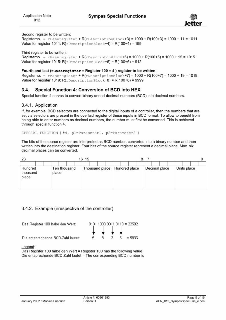
3.4. Special Function 4: Conversion of BCD into HEX Special function 4 serves to convert binary coded decimal numbers (BCD) into decimal numbers.
3.4.1. Application If, for example, BCD selectors are connected to the digital inputs of a controller, then the numbers that are set via selectors are present in the overlaid register of these inputs in BCD format. To allow to benefit from being able to enter numbers as decimal numbers, the number must first be converted. This is achieved through special function 4. SPECIAL FUNCTION [#4, p1=Parameter1, p2=Parameter2 ] The bits of the source register are interpreted as BCD number, converted into a binary number and then written into the destination register. Four bits of the source register represent a decimal place. Max. six decimal places can be converted. 23 16 15 8 7 0 Hundred thousand place
Ten thousand place
Thousand place Hundred place Decimal place Units place
3.4.2. Example (irrespective of the controller)
Legend: Das Register 100 habe den Wert = Register 100 has the following value Die entsprechende BCD Zahl lautet = The corresponding BCD number is
Article #: 60861993 Page 5 of 16January 2002 / Markus Friedrich Edition: 1 APN_012_SympasSpecFunc_e.doc

Application Note 012
Sympas Special Functions
The instruction SPECIAL FUNCTION [#4, p1=100, p2=101] has the result that value 5836 is written into register 101.
3.4.3. Note No integer registers but only floating-point registers can be used for special function 4.
3.5. Special Function 5: Conversion of HEX into BCD Special function 5 serves to convert decimal numbers into binary coded decimal numbers (BCD). This is the analog function of special function 4 but in reverse direction.
3.6. Special Function 7: Define Network Address Note: Special function 7 is only relevant when using the PASE-Eplus. When using the PASE-Eplus, the JetWay network address is set via four DIL switches on the E-CPUplus. Therefore, only network addresses from 1 through 15 can be assigned. Special function 7 is used to assign higher network addresses. SPECIAL FUNCTION [#7, p1=source register, p2=destination register] The source register contains the new network address (value range: 1 through 42). The destination register contains the new baud rate for the JetWay. Value 30 = 19200 baud, and 5 = 115200 baud.
Article #: 60861993 Page 6 of 16January 2002 / Markus Friedrich Edition: 1 APN_012_SympasSpecFunc_e.doc

Application Note 012
Sympas Special Functions
3.7. Special Functions 10, 11 and 12
3.7.1. Notes on Special Functions 10, 11 and 12 Special functions 10, 11 and 12 are only relevant for the DELTA. Starting from D-CPU version 1.05, it is possible to transfer register values via CAN-bus to one or several other DELTA or PASE-E controllers. This is realized by the D-CAN1 submodule in submodule socket 1 or 2 on the D-CPU. Individual register values or entire register blocks with up to 64 values can be transmitted. The values sent by a controller are received and buffered by all nodes at the bus. The D-CAN1 submodule can read the received register block via application program. Register values received by the nodes that are not required anymore need not be read. A max. number of 12 nodes can be connected. On each module, a register block of 64 registers is reserved for each node. The received register values are stored in these registers. Communication between D-CPU and D-CAN 1 submodule is realized by means of registers directly on the submodule, and by the three special functions 10, 11 and 12. The first parameter of each of the three special functions contains the number of the first register of a parameter register block, which contains further function parameters. The second parameter contains the number of the first register of the result register block. The flexible concept of the DELTA allows various equipping variants. Modules of external manufacturers can also be inserted but are not detected automatically. Therefore, the operating system of the DELTA must be informed which submodule is plugged in which submodule socket before the D-CAN1 submodule is accessed. For this purpose, a register is assigned to each of the two submodule sockets: Slot 1: register 61688 Slot 2: register 61689 Depending on which submodule socket the D-CAN1 submodule is plugged, the corresponding register must be loaded at the beginning of the application program. Value 1 must be loaded for the D-CAN1 submodule with master-master operation in version 1.xx. Note: A D-CPU with board revision 03 is required to operate the D-CAN1 submodule!
Article #: 60861993 Page 7 of 16January 2002 / Markus Friedrich Edition: 1 APN_012_SympasSpecFunc_e.doc

Application Note 012
Sympas Special Functions
3.7.2. Special Function 10: CAN: Connect After switching on the controller, the D-CAN1 submodule does not yet participate in the bus traffic. Therefore, no values can be sent or received (red LED is flashing). Connection to the bus is only established through special function 10 (red LED goes out). SPECIAL FUNCTION [#10, p1=ParamRegNum, p2=ResRegNum] The parameter register block (begins with p1) comprises 5 registers. Register number Meaning p1 + 0 Submodule socket 1 or 2 of the D-CAN1 submodule on the D-CPU p1 +1 Node numbers 2 to 13
Make sure that each number is only assigned once in the network. p1 + 2 Baud rate, 1 through 4
1 = 125 kBaud 2 = 250 kBaud 3 = 500 kBaud 4 = 1000 kBaud All nodes must operate with the same baud rate. The maximum possible baud rate depends on the overall line length.
p1 +3 Reserved, should contain -1 p1 +4 Reserved, should contain 0 The result register block (begins with p2) comprises 2 registers: Register number Meaning p2 + 0 Software version number * 100, (e.g. register content 105 � version 1.05) p2 +1 Module type / hardware version Establishing the connection might take several milliseconds. During this time, the busy bit in the status register (register 63x00, x = 3 for submodule socket 1 and x = 4 for submodule socket 2, bit 16) of the D-CAN1 submodule is set. It is necessary to wait until the busy bit is cleared before the functions described below can access the module.
3.7.2.1. Example Prior to calling special function 10, registers 100 to 104 are written as follows: Register 100 = 1 Submodule socket Register 101 = 5 Node Number Register 102 = 3 Baud Rate Register 103 = -1 Reserved Register 104 = 0 Reserved SPECIAL FUNCTION [#10, p1=100, p2=110] After successful execution of special function 10, the D-CAN1 submodule in submodule socket 1 (register 100) with node number 5 (register 101) and baud rate 500 kBaud (register 102) participates in the Canbus. Register 110 now contains the version number of the firmware of the D-CAN1 submodule, and register 111 the hardware version.
Article #: 60861993 Page 8 of 16January 2002 / Markus Friedrich Edition: 1 APN_012_SympasSpecFunc_e.doc

Application Note 012
Sympas Special Functions
3.7.3. Special Function 11: CAN: Send Data Now that the connection to the CAN-bus has been established by means of special function 10, special function 11 allows to send register contents to other controllers via CAN-bus. SPECIAL FUNCTION [#11, p1=ParamRegNum, p2=ResRegNum] The parameter register block (begins with p1) has the following structure: Register number Meaning p1 + 0 Submodule socket 1 or 2 of the D-CAN1 submodule on the D-CPU p1 +1 Number of registers to be sent: 1 through 64 p1 +2 First register number in the register block of the D-CAN1 submodules of the other
controllers: 0 through 63 p1 +3 First register to be sent p1 +4 Second register to be sent p1 + ... Further registers to be sent The result register block is currently not being used. Two registers should be reserved for further expansions. After completed function, the busy bit in the status register (register 63x00, x = 3 for submodule socket 1, and x = 4 for submodule socket 2, bit 16) of the D-CAN1 submodule is set and starts sending. Query whether the busy bit has been reset to verify when the register block has been transmitted completely.
3.7.3.1. Example Three registers are to be sent via the D-CAN1 submodule in the second submodule socket. These values are to be stored in the D-CAN1 submodules of the other controllers starting from memory location number 20. Register 200 = 2 Submodule socket Register 201 = 3 Number of values Register 202 = 20 Number of the destination register Register 203 = 123456 Value 1 Register 204 = 40404 Value 2 Register 205 = -98765 Value 3 SPECIAL FUNCTION [#11, p1=200, p2=210] After successful execution of special function 11, registers 20 to 22 of the register block on the D-CAN1 submodules of the other controllers contain the transmitted values: Register 20 = 123456 Register 21 = 40404 Register 22 = -98765 Register 210 (p2) and the subsequent registers are currently not yet being influenced (registers 210 and 211 should be reserved however).
Article #: 60861993 Page 9 of 16January 2002 / Markus Friedrich Edition: 1 APN_012_SympasSpecFunc_e.doc

Application Note 012
Sympas Special Functions
3.7.4. Special Function 12: CAN: Fetch Data Setting the respective bit in the status register (register 63x00 = 3 for submodule socket 1, and x = 4 for submodule socket 2) indicates that another controller has received a register block completely. One bit for each of the max. 12 nodes exists in the status register. This allows to determine by means of the bit position from which controller values have just been received. In two further registers (63x10 and subsequent, x = 3 for submodule socket 1, and x = 4 for submodule socket 2) per node can be read in which area of the register block the received values are stored for this node. By means of special function 12, a register block of the desired node can be read: SPECIAL FUNCTION [#12, p1=ParamRegNum, p2=ResRegNum] The parameter register block (begins with p1) comprises 4 registers: Register number Meaning p1 + 0 Submodule socket 1 or 2 of the D-CAN1 submodule on the D-CPU p1 +1 Number of registers to be read: 1 through 64 p1 +2 Number of the first register to be read from the register block: 0 through 63 p1 +3 Number of the node whose values are to be read: 2 through 13 The read values are stored in the destination register. The information whether the register block has changed since it was read the last time is stored in the first register, which is determined by p2. Therefore, it reflects the status of the corresponding bit in the status register. If no new values have been received, the register contains value 0. If new values have been received, the register contains value 255. The received register values are stored in the following registers. At the beginning of the read operation, the D-CAN1 submodule resets the 'block changed' bit in the status register.
3.7.4.1. Example Three registers from the register block of the node with number 7 are to be read from the D-CAN1 submodule in the first submodule socket starting from value number 10. Register 300 = 1 Submodule socket Register 301 = 3 Number of values Register 302 = 10 Number of the source register Register 303 = 7 Node number SPECIAL FUNCTION [#12, p1=300, p2=310] After successful execution of special function 12, register 310 of the D-CPU contains value 0 when the node with number 7 has not sent any new values since the last read operation, or value 255 when new values have been received. Registers 311 through 313 contain the received values.
3.7.4.2. Note When a register block was received, the ‚block changed’ bit in the status register is set but the corresponding register block is not blocked. This means that the data are cleared when the transmitting node sends a register immediately after the first transmission and the receiver has not yet fetched the values of the first transmission. While the D-CPU reads a register block, it is even possible that a new register block arrives via the CAN-bus and the D-CPU thus reads part of the values of the first transmission and part of the second transmission. The data within a register are consistent, however.
Article #: 60861993 Page 10 of 16January 2002 / Markus Friedrich Edition: 1 APN_012_SympasSpecFunc_e.doc

Application Note 012
Sympas Special Functions
3.8. Special Function 20: Square Root Value range of argument: 0 and positive numbers Value range of result: 0 and positive numbers Potential errors: negative number as argument Computing time: approx. 1.1 ms
3.9. Special Function 21: Sine Value range of argument: -1000 through +1000 (radian measure!) Value range of result: -1 through +1 Potential errors: none Computing time: approx. 4.5 to 5 ms
3.10. Special Function 22: Cosine Value range of argument: -1000 through +1000 (radian measure!) Value range of result: -1 through +1 Potential errors: none Computing time: approx. 5 ms
3.11. Special Function 23: Tangent Value range of argument: -1000 through +1000 (radian measure!) Value range of result: -1E13 through +1E13 Potential errors: none Computing time: approx. 10 ms
3.12. Special Function 24: Arc Sine Value range of argument: -1 through +1 Value range of result: -�/2 through +�/2 Potential errors: argument outside -1..+1 Computing time: approx. 6.5 ms
-1
-0,5
0
0,5
1
x
-PI/2 +PI/2+PI/4-PI/4 0
Article #: 60861993 Page 11 of 16January 2002 / Markus Friedrich Edition: 1 APN_012_SympasSpecFunc_e.doc
Application Note 012
Sympas Special Functions
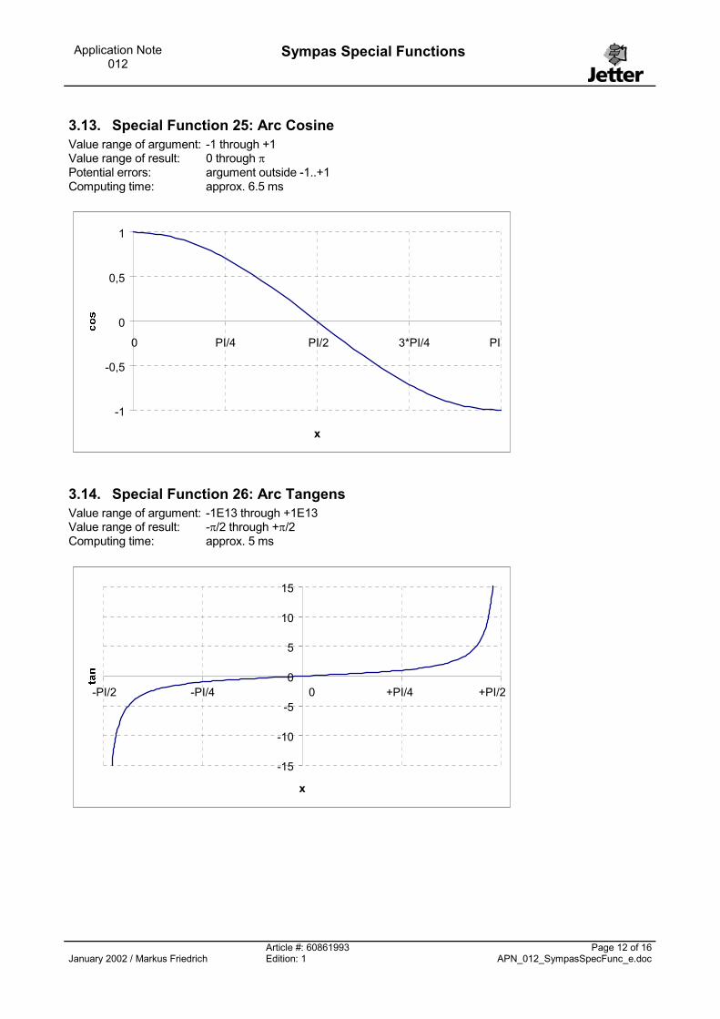
3.13. Special Function 25: Arc Cosine Value range of argument: -1 through +1 Value range of result: 0 through � Potential errors: argument outside -1..+1 Computing time: approx. 6.5 ms
-1
-0,5
0
0,5
1
x
0 PI/4 PI/2 3*PI/4 PI
3.14. Special Function 26: Arc Tangens Value range of argument: -1E13 through +1E13 Value range of result: -�/2 through +�/2 Computing time: approx. 5 ms
-15
-10
-5
0
5
10
15
x
+PI/2+PI/4-PI/4-PI/2 0
Article #: 60861993 Page 12 of 16January 2002 / Markus Friedrich Edition: 1 APN_012_SympasSpecFunc_e.doc

Application Note 012
Sympas Special Functions
3.15. Special Function 27: Exponential Function („e high“) Value range of argument: -30 through +30 Value range of result: 1E-13 through 1E13 Potential errors: argument outside -30..+30 Result in case of error: CRASH!!!! Computing time: approx. 4.5 ms
0,000010,0001
0,0010,01
0,11
10100
100010000
100000
-10 -8 -6 -4 -2 0 2 4 6 8 10
x
3.15.1. Note Be careful when using this special function: ignoring the value range of the first parameter might cause the controller to crash.
3.16. Special Function 28: Natural Logarithm („ln“) Value range of argument: 1E-13 through 1E13 Value range of result: -30 through +30 Potential errors: argument < 1E-13 Result in case of error: CRASH!!!! Computing time: approx. 2 to 5 ms
3.16.1. Note Be careful when using this special function: ignoring the value range of the first parameter might cause the controller to crash.
3.17. Special Function 29: Absolute Value Value range of argument: any value Value range of result: value of the argument Potential errors: none Computing time: approx. 0.5 ms
3.18. Special Function 30: MOD Value range of argument: any value Value range of result: integer digit positions of the argument Value range of result 2: decimal positions of the argument Potential errors: none
Article #: 60861993 Page 13 of 16January 2002 / Markus Friedrich Edition: 1 APN_012_SympasSpecFunc_e.doc
Application Note 012
Sympas Special Functions
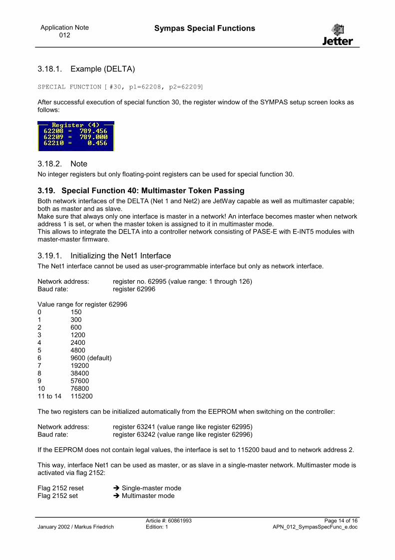
3.18.1. Example (DELTA) SPECIAL FUNCTION [#30, p1=62208, p2=62209] After successful execution of special function 30, the register window of the SYMPAS setup screen looks as follows:
3.18.2. Note No integer registers but only floating-point registers can be used for special function 30.
3.19. Special Function 40: Multimaster Token Passing Both network interfaces of the DELTA (Net 1 and Net2) are JetWay capable as well as multimaster capable; both as master and as slave. Make sure that always only one interface is master in a network! An interface becomes master when network address 1 is set, or when the master token is assigned to it in multimaster mode. This allows to integrate the DELTA into a controller network consisting of PASE-E with E-INT5 modules with master-master firmware.
3.19.1. Initializing the Net1 Interface The Net1 interface cannot be used as user-programmable interface but only as network interface. Network address: register no. 62995 (value range: 1 through 126) Baud rate: register 62996 Value range for register 62996 0 150 1 300 2 600 3 1200 4 2400 5 4800 6 9600 (default) 7 19200 8 38400 9 57600 10 76800 11 to 14 115200 The two registers can be initialized automatically from the EEPROM when switching on the controller: Network address: register 63241 (value range like register 62995) Baud rate: register 63242 (value range like register 62996) If the EEPROM does not contain legal values, the interface is set to 115200 baud and to network address 2. This way, interface Net1 can be used as master, or as slave in a single-master network. Multimaster mode is activated via flag 2152: Flag 2152 reset � Single-master mode Flag 2152 set � Multimaster mode
Article #: 60861993 Page 14 of 16January 2002 / Markus Friedrich Edition: 1 APN_012_SympasSpecFunc_e.doc

Application Note 012
Sympas Special Functions
When switching on the controller, flag 2152 is always cleared.
3.19.2. Initializing the Net2 Interface When switching on the controller, the Net2 interface is always set to PRIM (user-programmable interface). When using the interface as JetWay interface, the following 3 registers need to be written: Network address: register no. 62991 (value range: 1 through 126) Baud rate: register 62990 (value range like register 62996, see chapter 3.19.1) Configuration: register 62989 The Net2 interface operates as JetWay interface when bit 0 in register 62989 is set. Bits 1 through 7 in this register are ignored. Multimaster mode is activated via flag 2153: Flag 2153 reset � Single-master mode Flag 2153 set � Multimaster mode When switching on the controller, flag 2153 is always cleared.
3.19.3. Programming Network commands can only be issued by the network master. If an error occurs when the network is accessed, flags 2110 (timeout last network access) and 2111 (network timeout since reset) are set. The timeout in milliseconds is set via register 61588 for the Net1 interface, and via register 61511 for the Net2 interface. The reset values are 250 [ms] each. The timeout should be set to the same value for all nodes.
3.19.4. Master-Master Operation / Multimaster Mode In multimaster mode, the master function (being able to read and write registers) alternates between the controllers involved. The network address is assigned as in single-master mode: �� each network address may only be assigned once �� a network address unequal 1 is assigned to the JetWay slaves �� network address 1 is assigned to the master. Passing on the master is initiated by the controller program. Special function 40 is used for this purpose: SPECIAL FUNCTION[#40, p1=SupposedMaster, p2=ActualMaster] p1: Network address of the node supposed to act as network master (indirect addressing possible) p2: Network address of the node that actually received the master (indirect addressing possible) The operating system transfers the master function from the network master to the slave if the respective enable flag (2152 / 2153) is set and if the other network interface is not master in its network. Whether an interface currently acts as master or as slave can be read from registers: Net1: Register 61587 Net2: Register 61509 A register content of 0 indicates that the interface operates as JetWay slave, a value unequal 0 (255) means that the interface works as JetWay slave.
Article #: 60861993 Page 15 of 16January 2002 / Markus Friedrich Edition: 1 APN_012_SympasSpecFunc_e.doc
Application Note 012
Sympas Special Functions
When the enable flags are not set, the DELTA does not react on the master transfer and therefore, a timeout error is triggered in the network master. When enable is set but the application program is stopped, the operating system passes the master to the next node immediately . If a DELTA with a network address unequal 1 has become master, the application program must carry out network accesses. After completed network activities, the master must be passed on with special function 40. If the master does not become active in the network, the node with number ‘1’ automatically becomes master again when the monitoring time (can be set) has expired. This monitoring time is set in register 61512 in multiples of the network timeout (61588 / 61511). The value after a reset = 3 (750 ms). Register 61512 is also used to define how often a master maximally attempts to pass the master function to another node. With each attempt, the address of the node that is to receive the master token is incremented by one. If it was not possible to pass on the token after this number of attempts, a master with an address unequal 1 automatically switches over to slave and relinquishes the network to the node with number 1. For network administration purposes, the highest address of the node in the network must be written to a register: Register 61515 highest network address This register must be set to the same value in all controllers involved. For optimized data transmission of register blocks in multi-master mode, you can also use the SYMPAS instruction COPY. Up to 21 registers can be transmitted with one network instruction. A 50000 register number must be specified for the source or destination register. The other register must be a user register. If these restrictions are not observed, the register values will be transmitted individually.
3.20. Special Function 252: Determine Checksum SPECIAL FUNCTION [#252, p1=Checksum, p2=start register] Special function 252 serves to add up register values to a checksum. The checksum is written to the register that was specified as first parameter (Checksum). Adding up is started with the register specified as second parameter (Start register). The checksum ends with the last user register. PASE - E � Register 8191 DELTA � Register 20479
Article #: 60861993 Page 16 of 16January 2002 / Markus Friedrich Edition: 1 APN_012_SympasSpecFunc_e.doc