Embed Size (px)
Citation preview


- 1 -
- JANUS B - - Flight Manual -
Table of contents Page
Amendments 2
Operating data and limitations 3 – 5b
Operating instructions 6 – 16
Minimum equipment 16
Wing and tail setting,control surface movements 17
Weight and C.G. range 18 – 19a
Cockpit load 20
Water ballast 20a
Three-side view,control surface movements 21
Weight and balance 22
Check List 23 – 24
- 2 a -
- JANUS B - FLIGHT MANUAL
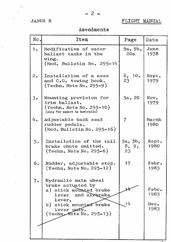
AMENDMENT LIST(log of revisions)
No. Reference / short title Page Date
8. Modification Bulletin No. 295-23Supplements to sections 5(C.G. positions) and 6 (loading plan).-Optional up to S/N 180,standard on S/N 181 and on-
5a, 18, 19,19A, 19B,19C, 20 Dec.
19839. Technical Note No. 295-17
Optional installation of a tail wheel(instead of standard skid)
19, 22, 23 Dec.1986
10. Technical Note No. 295-18Optional mounting provision for trimballast weights
5a, 20 May1987
11. Technical Note No. 295-20Tow releases „EUROPA G 88“ and „E 85“,weak link 3, 5
April1990
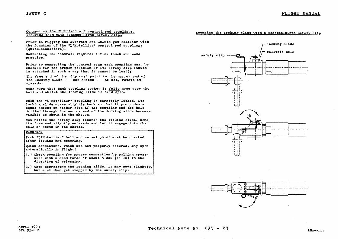
12. Technical Note No. 295-23Safety clip for „L’Hotellier“ ball andswivel joints
supplement.page
April1993
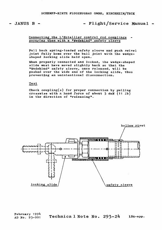
13. Technical Note No. 295-24„Wedekind“ safety sleeve for „L’Hotellier“ball and swivel joints
supplement.page
Feb.1994
14. Technical Note No. 295-28Empty mass c/g positions for variousminimum front seat loads-optional up to S/N 180-
5a, 18, 19,19A, 19B,19C, 20
July1999
15. Technical Note No. 295-29Minimum front seat load with two occupants- optional for all serial numbers-
20 April2000


- 9a -
- JANUS B - FLIGHT MANUAL
Water ballast
The water tanks are integral compartments in the wing.
Filling
The tanks are filled through a hole on the upper surface of the wing nose. It is
closed by a plugged in cap which has a small 5 mm dia hole for pulling it out
by means of the provided pin. The hole in the cap also serves as a vent hole
and therefore should be kept open. The tanks have an additional vent by a
plastic tube with outlet at the end rib of the wing at the outboard aileron root.
The tanks have a capacity of about 120 liter each. The quantity of water
however to be filled into the tanks must be compensated with the respective
pilots’ weight. The permitted maximum weight of 620 kg, 1367 lb. must not be
exceeded (see page 20a, loading plan).
Both tanks must be filled with the same water quantity, otherwise the lateral
stability would be detrimentally influenced.
Due to the installed buffles no noticeable shifting of the water is observed.
Draining
The water is drained off through a hole in the lower wing surface at the root.
The connection of the draining off device of the wings to the fuselage is made
automatically when attaching the wings.
The dump valve operating handle (knob) is installed at the right-hand side of
the front cockpit. Pushing the handle forward opens the dump valve in the
wings, moving the handle down locks it in that position.
In the improbable case that the water tanks should be unequally drained off or
only one-side, the speed due to the higher weight
Modification Bulletin No. 295-14 June 1978

- 9b -
- JANUS B - FLIGHT MANUAL
is to be increased. Stalls then should be avoided.
During the landing run care is to be taken of the tendency for the glider to
ground loop due to the earlier ground contact of the heavier wing.
Note 1
When flying at air temperatures lower than 0 degr. (32 degr. F) drain off the
water in any case, to avoid icing. Flying with water ballast requires the
installation of a thermometer to measure the outer air temperature.
Note 2:
If an average climbing speed of not more than 1.5 m/sec, 5 ft./sec. or 3 knots
is expected, the use of water ballast is not recommended. Likewise water
ballast is not worthwhile when flying in narrow thermals where highly banked
circling is required.
Note 3:
Drain off the water when off-field landings must be conducted.
The time required to drain off full water tanks in level flight is about 4 minutes.
Water may be retained for landing on prepared runways.
Note 4:
Never park the glider with filled water tanks at low temperatures, in order to
avoid icing.
Before storing the glider fully drain off the water, take off the cap of the filling
holes and let the tanks dry.
Note 5:
If the dump valve should leak when the tanks are full, the seals should be
greased before the tanks are next filled.
Modification Bulletin No. 295-14 June 1978


- 14 -
- JANUS B - FLIGHT MANUAL
The sideslip should be initiated or recovered with air brakes retracted to avoid
the influence of turbulence on the horizontal tail surface.
The glider touches down on the landing wheel and tail skid simultaneously.
The wheel brake (drum brake) works well. It is operated by a handle on the
sticks.
To avoid a long landing run it is advisable to touch down at a minimum speed
of 70 to 80 km/h, 43 to 50 mph, 38 to 43 knots, dependent on the wing
loading. Landing with a speed of 95 km/h, 59 mph, 51 knots instead of 70
km/h, 43 mph, 38 knots, means doubling the time to slow down the energy
and considerably increases the running distance.
Emergencies
The sailplane can be held in a stalling position with fully pulled sstick and
necessary rudder control. Applying full rudder in a stall brings the glider into a
spin.
Safe recovery from the spin is effected by the STANDARD METHOD, which is
defined as:
a) Apply opposite rudder (i.e. against the direction of the spin);
b) Pause;
c) Ease the control stick forward until rotation ceases and the glider becomes
unstalled;
d) Take the rudder into neutral position and allow the glider to dive out.
The loss of height in one complete rotation of the spin is 80 to 100 meters.
After having initiated action for recovery from the spin the glider speeds up
very fast.

- 15a -
- JANUS B - FLIGHT MANUAL
Aerobatic maneuversThe following acrobatic maneuvers are permitted:
Inside loops, Turns, Spins, Lazy eights.
In the following the parenthesized speeds refer to higher wing loading (two-
seat).
Inside loopsEntry to the maneuver with flaps in position -7o at a speed of 180 (200) km/h.
In the medium part of the maneuver flap position 0o is preferable.
Pull out speed : 160 (175) km/h.
TurnsEntry to the maneuver with flaps in position -7o at a speed of 180 (200) km/h.
Full rudder in the vertical climb at a speed about 140 km/h.
SpinsPossible only with the C.G. in an aft position.
Positive flap position +8o.
Entry to the spin from a sharp stall applying full rudder. The control stick
should be pulled during the spin.
Recovery from the spin by the “Standard Method”:
Recovery from the spin is effected by the STANDARD METHOD:
Opposite rudder and control stick eased forward, aileron neutral.
Pull-out speed: 140 to 160 km/h dependent on flap position and recovery
method.
At aft C.G. about one turn is needed from the beginning of the recovery
method.
Lazy eightsEntry to the maneuver with flaps in position -7o at a speed of 180 (200) km/h.
Climbing with 30o to 45o and entering the turn at 120 km/h.
Pull-out speed: 160 (180) km/h.


JANUS B Loading table Seat load (Crew incl. parachutes)
Seat load
two persons one person min. max. min. max.
front seat
kg lbs
70 * 154
110 * 242
70 * 154
110* 242
back seat
kg lbs
no limit
110 * 242
--- ---
* Note: As the actual minimum or maximum seat load of this sailplane (to which this manual refers) may differ from the above typical weights, the seat load pla- card in the cockpit must always show the actual weights from the log chart on page 19 C. At less cockpit load, compensating ballast on the front seat is required. The ballast weight (lead or sand cushion) is to be securely fastened onto the front seat belt attachment fittings. Neither the maximum A.U. weight nor the max. weight of the non-lifting parts must be exceeded. C.G. position of the pilots (with parachute or back cushion) Front seat: 1300 mm (51.18 in.) ahead of datum Back seat: 190 mm ( 7.48 in.) ahead of datum Baggage compartment A maximum equipment of 25 kg (55 lb) can be fastened onto the mounting panel over the main landing wheel. The baggage compartment behind the wing spar stubs is suitable for installation of fixed equipment like oxygen cylinders or variometer flasks and/or for storage of light baggage like jackets etc. For the determination of the rearward empty weight C.G. a removable baggage load of 5 kg (11 lb) maximum is considered. Lever arm of the baggage: 1100 mm (43.3 in.) aft of datum
- 20 –
FLIGHT MANUAL Note: With both seats occupied, the placarded minimum front seat load may be reduced by the nose-heavy moment of loads on the rear seat as follows: Rear seat load (kg/lb) x 0.23 = load to be deducted from placarded minimum front seat load (kg/lb) Example:
Load on: Both seats occupied Placarded minimum may be reduced by
Front seat 85 (placarded minimum) 70 x 0.23 = 16 kg
Rear seat 70
Thus the minimum front seat load of this example is 69 kg. The seat load placard in the cockpit, however, remains unchanged ! MB 295-23 TN 295-28 TN 295-29 April 2000
- 20a -
- JANUS B - FLIGHT MANUAL
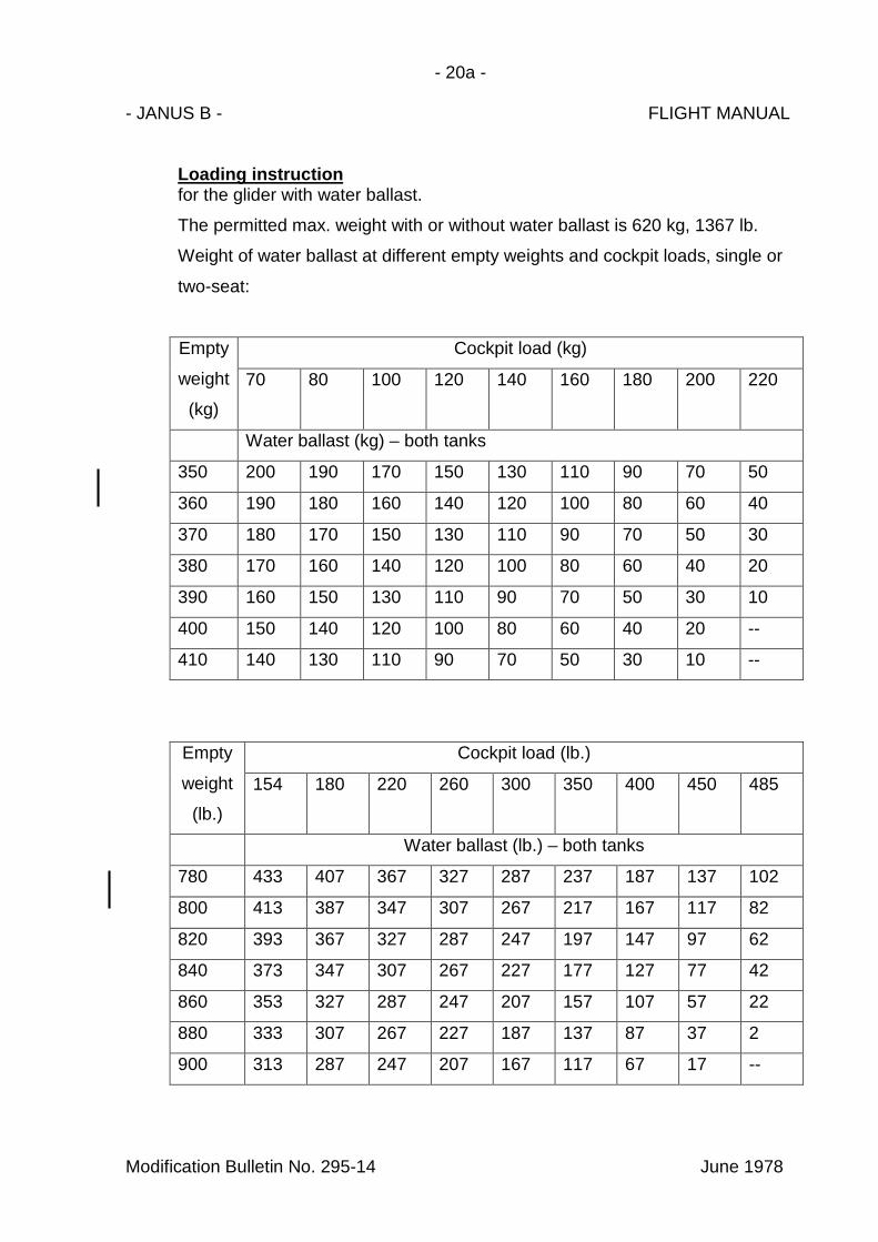
Loading instructionfor the glider with water ballast.
The permitted max. weight with or without water ballast is 620 kg, 1367 lb.
Weight of water ballast at different empty weights and cockpit loads, single or
two-seat:
Empty
weight
(kg)
Cockpit load (kg)
70 80 100 120 140 160 180 200 220
Water ballast (kg) – both tanks
350 200 190 170 150 130 110 90 70 50
360 190 180 160 140 120 100 80 60 40
370 180 170 150 130 110 90 70 50 30
380 170 160 140 120 100 80 60 40 20
390 160 150 130 110 90 70 50 30 10
400 150 140 120 100 80 60 40 20 --
410 140 130 110 90 70 50 30 10 --
Empty
weight
(lb.)
Cockpit load (lb.)
154 180 220 260 300 350 400 450 485
Water ballast (lb.) – both tanks
780 433 407 367 327 287 237 187 137 102
800 413 387 347 307 267 217 167 117 82
820 393 367 327 287 247 197 147 97 62
840 373 347 307 267 227 177 127 77 42
860 353 327 287 247 207 157 107 57 22
880 333 307 267 227 187 137 87 37 2
900 313 287 247 207 167 117 67 17 --
Modification Bulletin No. 295-14 June 1978


- I-
- JANUS B - SERVICE MANUAL
Table of contents Page
Assembly, disassembly 25 – 27
Maintenance 28 – 32
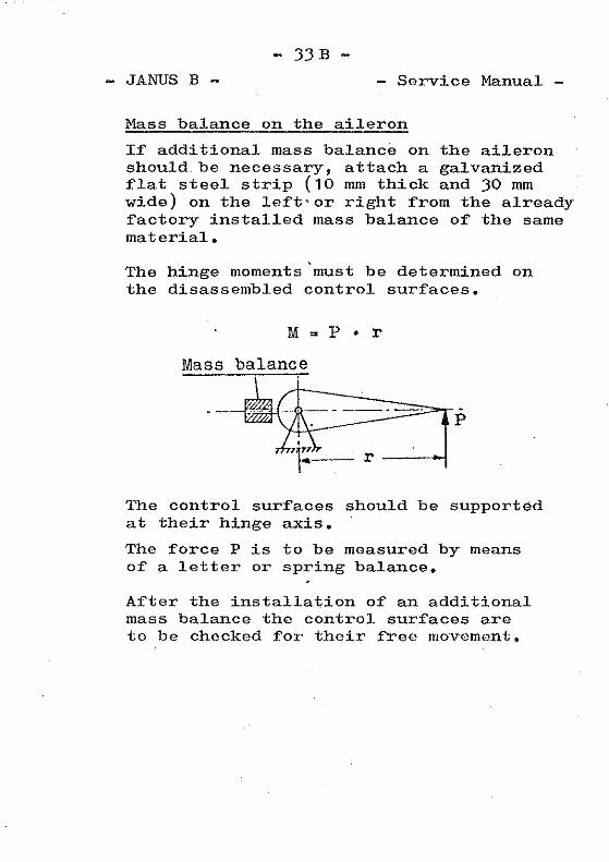
Hinge moments and weights of control surfaces 33A – 33B
Periodic and annual inspection 34 – 36
Determination of C.G. 36a
Control system views 37 – 39
Inspection for the extension of service life 40 – 41
Supplement of equipment and instrument 42 – 46
APPENDIX
Polar curves
Repair instructions
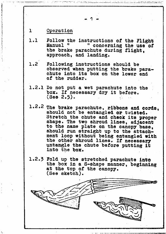
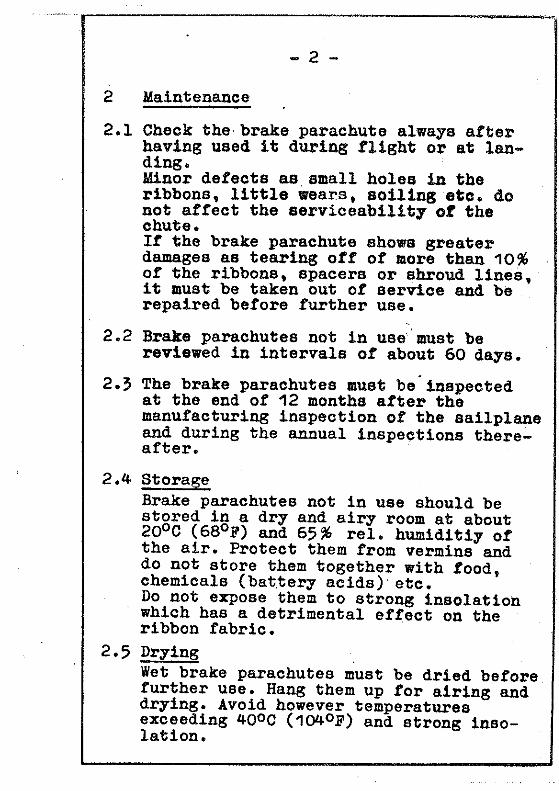
Operating and maintenance instructionsfor drag chutes
Technical Note No. 295-11

- I/1 -
- Janus B - SERVICE MANUAL
AMENDMENT LIST(log of revisions)
No. Reference / short title Page Date
1. Technical Note No. 295-9Optional additional nose tow release
28, 28A,29a, 34 July 1980
2. Technical Note No. 295-6Tail chute omitted
I Sept. 1980
3. Technical Note No. 295-11Service time I, 40, 41 April 1981
4. Technical Note No. 295-13Hydraulic disc brake (optional)
a) dual-actuated via handle on stick and air-brake lever
b) via handle on stick only
30, 30a
30, 30a
Febr. 1983
Dec. 1983
5. Modification Bulletin No. 295-20Technical Note No. 295-15Rudder control circuit- optional up to S/N 159- standard for S/N 162 and up
39
Nov. 1982
Febr. 1986
6. Technical Note No. 295-17Optional tail wheel 30, 36 Dec. 1986
7. Technical Note No. 295-20Tow release „E 85“ and „G 88“ 34 April 1990
8. Technical Note No. 295-11Hinge moments and weightsPrescribed inspectionsExtension of service time
33A3440, 41
Febr. 1991
9. Supplement of equipment and instruments I, 42, 43,
44, 45, 46
August2007


1990


- 36a -
- JANUS B - SERVICE MANUAL
Determination of the empty weight C.G.
For the determination of the empty weight C.G. position the sailplane is to be
assembled with closed canopy, with the permanent equipment installed and
without water ballast and without parachutes and pilots.
With the main wheel on the ground the tail is to be jacked up on a balance
about 42 cm (16.5 in.) above the floor, i.e. slope of rear top surface of
fuselage100 to 4.5, tail down or rear fuselage center line horizontal see page
22 of the Flight Manual.
Then the weight on the tail is to be determined with wings held level. The
distances a and b (see page 22 of the Flight Manual) are measured using a
plumb or gathered from the last weight and balance report.
The empty weight should be within the limits of the empty weight C.G. range
see page 18 and 19 of the Flight Manual.
Cross-country flight C.G. position
For cross-country flights it is recommended to determine the in-flight C.G. The
performance suffers with the C.G. too far out of the optimum range of 200 mm
(7,9 in.) to 300 mm (11.81 in.) aft of datum.
For the determination of the in-flight C.G. the sailplane is to be weighed with
all payload (pilot, chute, barograph, cushion, foto a.s.o.). Pay attention to the
right position of the rudder pedals and backrest.
C.G. in flight:
Xflight = (W2flight * b)/(Wempty + Wpayload) + a


- 42 -
- JANUS B - SERVICE MANUAL
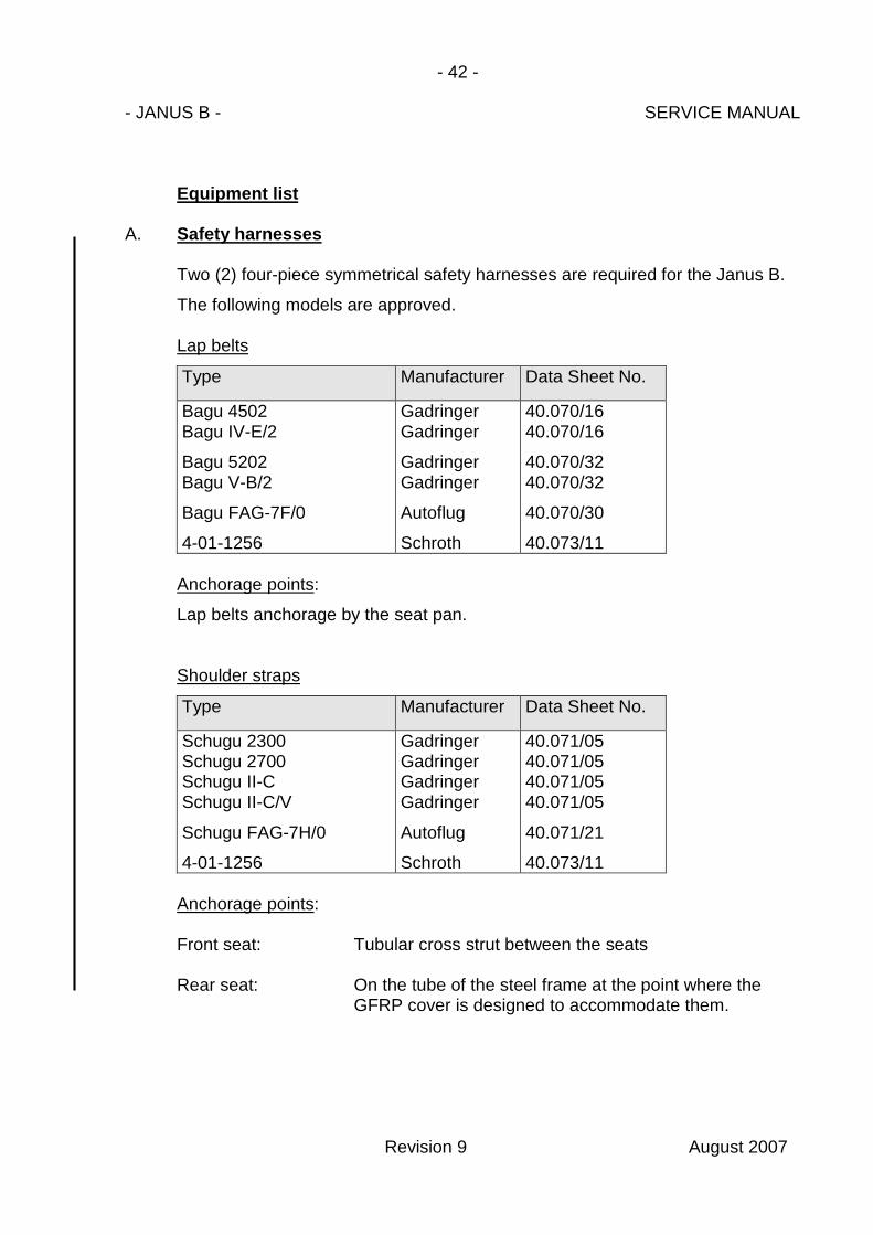
Equipment list
A. Safety harnesses
Two (2) four-piece symmetrical safety harnesses are required for the Janus B.
The following models are approved.
Lap belts
Type Manufacturer Data Sheet No.
Bagu 4502Bagu IV-E/2
Bagu 5202Bagu V-B/2
Bagu FAG-7F/0
4-01-1256
GadringerGadringer
GadringerGadringer
Autoflug
Schroth
40.070/1640.070/16
40.070/3240.070/32
40.070/30
40.073/11
Anchorage points:
Lap belts anchorage by the seat pan.
Shoulder straps
Type Manufacturer Data Sheet No.
Schugu 2300Schugu 2700Schugu II-CSchugu II-C/V
Schugu FAG-7H/0
4-01-1256
GadringerGadringerGadringerGadringer
Autoflug
Schroth
40.071/0540.071/0540.071/0540.071/05
40.071/21
40.073/11
Anchorage points:
Front seat: Tubular cross strut between the seats
Rear seat: On the tube of the steel frame at the point where theGFRP cover is designed to accommodate them.
Revision 9 August 2007
- 43 -
- JANUS B - SERVICE MANUAL
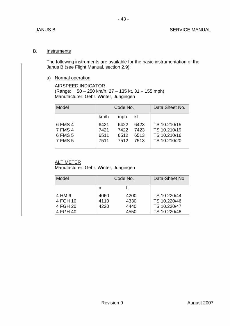
B. Instruments
The following instruments are available for the basic instrumentation of theJanus B (see Flight Manual, section 2.9):
a) Normal operation
AIRSPEED INDICATOR(Range: 50 – 250 km/h, 27 – 135 kt, 31 – 155 mph)Manufacturer: Gebr. Winter, Jungingen
Model Code No. Data Sheet No.
6 FMS 47 FMS 46 FMS 57 FMS 5
km/h mph kt
6421 6422 64237421 7422 74236511 6512 65137511 7512 7513
TS 10.210/15TS 10.210/19TS 10.210/16TS 10.210/20
ALTIMETERManufacturer: Gebr. Winter, Jungingen
Model Code No. Data-Sheet No.
4 HM 64 FGH 104 FGH 204 FGH 40
m ft
4060 42004110 43304220 4440
4550
TS 10.220/44TS 10.220/46TS 10.220/47TS 10.220/48
Revision 9 August 2007

- 44 -
- JANUS B - SERVICE MANUAL
b) Additional equipment(supplement equipment for normal operation a)
TURN & BANK INDICATOR with slip ball
Model Manufacturer Specif.-No.
WZ 402/31
IFR 51-12-2
ApparatebauGauting
Instruments andFlight ResearchWichita/USA.
10-241/8
TSO C 3 b
MAGNETIC COMPASS
Model Manufacturer Data-Sheet No.
FK 16C 2300C 2400
LudolphAirpathAirpath
L-10.410.3
VARIOMETERManufacturer: Gebr. Winter, Jungingen
Model Code-No. Specif.-No.
5 St VL5 St VLM5 St V5 St VM
all code numbersapproved
TS 10.230/11TS 10.230/12TS 10.230/13TS 10.230/14
Revision 9 August 2007

- 45 -
- JANUS B - SERVICE MANUAL
VHF-TRANSCEIVERS
Model Manufacturer Data Sheet No.
FSG 40 SFSG 50FSG 60FSG 70FSG 71 MFSG 90, 90H1FSG 2T
ATR 720ATR 720 AATR 720 BATR 720 CATR 500ATR 600ATR 600R01ATR 833
M760
W. Dittel GmbH.W. Dittel GmbH.W. Dittel GmbH.W. Dittel GmbH.W. Dittel GmbH.W. Dittel GmbH.W. Dittel GmbH.
Avionic DittelFilser Electronic GmbH.Filser Electronic GmbH.Filser Electronic GmbH.Filser Electronic GmbH.Filser Electronic GmbH.Filser Electronic GmbH.Filser Electronic GmbH.
Microair
10.911/4510.911/7110.911/7210.911/8110.911/8110.911/98JTS10.911/103JTSO
10.911/7010.911/7410.911/8010.911/83O.10.911/113JTSOO.10.911/106JTSOO.10.911/115JTSOEASA.210.0193
CAA LA301068
AR 3201AR 3201-( )AR 4201
BeckerBeckerBecker
10.911/7610.911/7610.911/87
DILUTER DEMAND OXYGEN SYSTEMS
Model Manufacturer Code-No. Data Sheet No.
HöhenatmerHLa 758
Dräger E 20088 40.110/1
Miniregler Dräger E 24902 40.110/19Miniregler Dräger E 24903 40.110/19
EMERGENCY LOCATOR TRANSMITTER
Model Manufacturer Data-Sheet No.
EB-2 B (CD)ELT 10ELT 8.13000ACK E01
Mar Tech DivisionNarco AvionicsDorne & Margolin Inc.PointerACK Technologies Inc.
10.915/210.915/310.915/510.915/610.915/9
Revision 9 August 2007
- 46 -
- JANUS B - SERVICE MANUAL
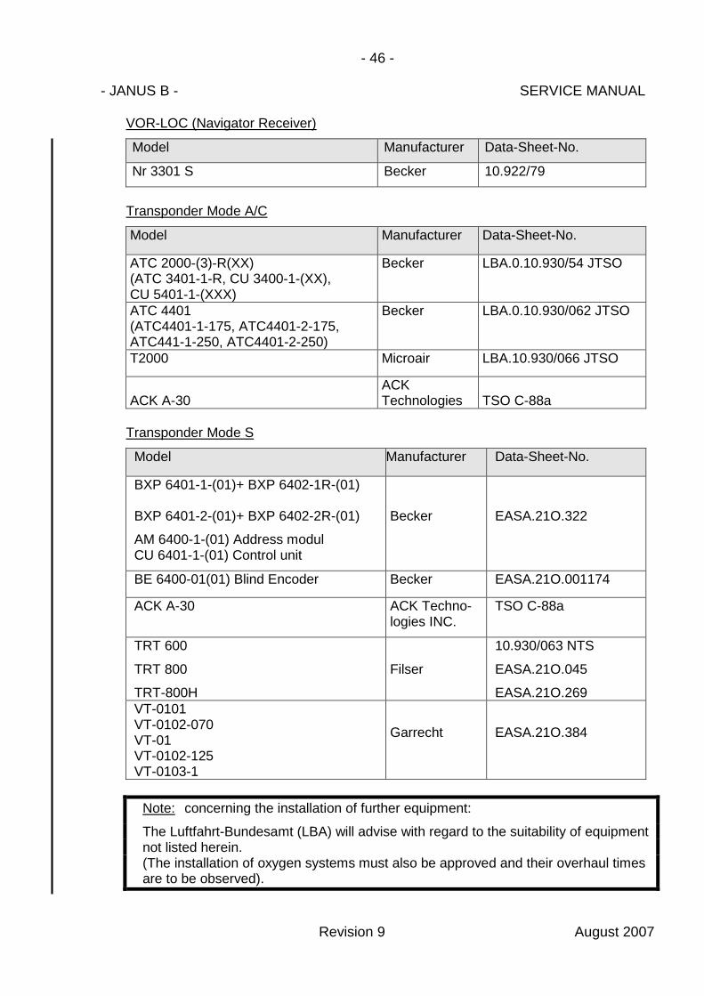
VOR-LOC (Navigator Receiver)
Model Manufacturer Data-Sheet-No.
Nr 3301 S Becker 10.922/79
Transponder Mode A/C
Model Manufacturer Data-Sheet-No.
ATC 2000-(3)-R(XX)(ATC 3401-1-R, CU 3400-1-(XX),CU 5401-1-(XXX)
Becker LBA.0.10.930/54 JTSO
ATC 4401(ATC4401-1-175, ATC4401-2-175,ATC441-1-250, ATC4401-2-250)
Becker LBA.0.10.930/062 JTSO
T2000 Microair LBA.10.930/066 JTSO
ACK A-30ACKTechnologies TSO C-88a
Transponder Mode S
Model Manufacturer Data-Sheet-No.
BXP 6401-1-(01)+ BXP 6402-1R-(01)
BXP 6401-2-(01)+ BXP 6402-2R-(01)
AM 6400-1-(01) Address modulCU 6401-1-(01) Control unit
Becker EASA.21O.322
BE 6400-01(01) Blind Encoder Becker EASA.21O.001174
ACK A-30 ACK Techno-logies INC.
TSO C-88a
TRT 600
TRT 800
TRT-800H
Filser
10.930/063 NTS
EASA.21O.045
EASA.21O.269VT-0101VT-0102-070VT-01VT-0102-125VT-0103-1
Garrecht EASA.21O.384
Note: concerning the installation of further equipment:
The Luftfahrt-Bundesamt (LBA) will advise with regard to the suitability of equipmentnot listed herein.(The installation of oxygen systems must also be approved and their overhaul timesare to be observed).
Revision 9 August 2007


Tooli
ng &
Com
posit
es
Bire
sin®
CR
122
1 /
4
Version 06 / 2012
Biresin® CR122
Product Data Sheet
Composite resin system
Areas of Application
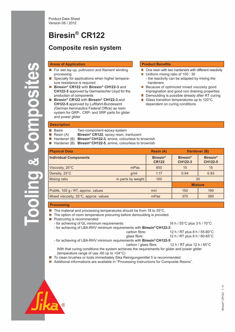
For wet lay-up, pultrusion and filament winding processing Specially for applications when higher tempera-ture resistance is requiredBiresin® CR122 with Biresin® CH122-3 and CH122-5 approved by Germanischer Lloyd for the production of componentsBiresin® CR122 with Biresin® CH122-3 and
CH122-5 approved by Luftfahrt-Bundesamt (German Aeronautics Federal Office) as resin system for GRP-, CRP- and SRP parts for glider and power glider
Product Benefits
One resin with two hardeners with different reactivityUniform mixing ratio of 100 : 30- the reactivity can be adapted by mixing the hardenersBecause of optimized mixed viscosity good impregnation and good non draining properties Demoulding is possible already after RT curingGlass transition temperatures up to 120°C dependent on curing conditions
Processing
The material and processing temperatures should be from 18 to 35°C. The option of room temperature precuring before demoulding is provided.Postcuring is recommended:- for achieving of GL minimum requirements: 16 h / 55°C plus 3 h / 70°C- for achieving of LBA-RHV minimum requirements with Biresin® CH122-3: carbon fibre: 12 h / RT plus 8 h / 55-60°C glass fibre: 12 h / RT plus 8 h / 60-65°C- for achieving of LBA-RHV minimum requirements with Biresin® CH122-5: carbon / glass fibre: 12 h / RT plus 12 h / 65°C With that curing conditions the system achieves the requirements for glider and power glider (temperature range of use -60 up to +54°C)To clean brushes or tools immediately Sika Reinigungsmittel 5 is recommended.Additional informations are available in “Processing Instructions for Composite Resins”.
Description
Basis Resin (A) Hardener (B)Hardener (B)
Two-component-epoxy-system Biresin® CR122, epoxy resin, tranlucent Biresin® CH122-3, amine, colourless to brownishBiresin® CH122-5, amine, colourless to brownish
Physical Data Resin (A) Hardener (B)
Individual Components Biresin® CR122
Biresin®
CH122-3Biresin®
CH122-5Viscosity, 25°C mPas 850 15 15Density, 25°C g/ml 1.17 0.94 0.93Mixing ratio in parts by weight 100 30
MixturePotlife, 100 g / RT, approx. values min 150 190Mixed viscosity, 25°C, approx. values mPas 370 380

Bire
sin®
CR
122
2 /
4
Development of Viscosity of Biresin® CR122-Resin(A)-Hardener(B)-Mixtures, 25°C
6000
5000
4000
3000
2000
1000
00 30 60 90 120 150
Time [min]
Vis
cosi
ty [m
Pas
]
0
1000
2000
3000
4000
5000
6000
0 30 60 90 120 150
Viskosität in mPas
Zeit
in m
in
Biresin® CH122-3 Biresin® CH122-5
Development of Exotherm of Biresin® CR122-Resin(A)-Hardener(B)-Mixtures, 100g / 23°C, insulated,
0 30 60 90 120 150 180 210 240 270 Time [min]
250
200
150
100
50
0
T
empe
ratu
re [
°C]
0
50
100
150
200
250
00:00 00:30 01:00 01:30 02:00 02:30 03:00 03:30 04:00 04:30
Biresin® CH122-3
Biresin® CH122-5
Test conditions: rotation viscosimeter, plate/plate, measuring gap 0,2 mm

Bire
sin®
CR
122
3 /
4
Part 4: approx. values after 12 h / 120 °C (source: Sika internal) Biresin® CR122 resin (A) with hardener (B) Biresin® CH122-3 CH122-5Density ISO 1183 g/cm³ 1.17 1.16Shore hardness ISO 868 - D 86 D 86Flexural E-Modulus ISO 178 MPa 2,700 2,700Tensile E-Modulus ISO 527 MPa 2,800 2,800Flexural strength ISO 178 MPa 128 125Compressive strength ISO 604 MPa 120 118Tensile strength ISO 527 MPa 84 84Elongation at break ISO 527 % 5.4 5.6Impact resistance ISO 179 kJ/m² 52 59
Mechanical Data, neat resin specimen at different post curing conditionsPart 1: approx. values after 16 h / 55°C (source: accredited testing institute) Biresin® CR122 resin (A) with hardener (B) Biresin® CH122-3 CH122-5Density ISO 1183 g/cm³ 1.17 1.17Flexural E-Modulus ISO 178 MPa 3,500 3,500Tensile E-Modulus ISO 527 MPa 3,300 3,400Flexural strength ISO 178 MPa 121 121Elongation at maximum flexural strength ISO 527 % 4.9 4.9Tensile strength ISO 527 MPa 70 70Water absorption ISO 175 % 0.32 0.33
Part 2: approx. values after 16 h / 55°C + 3 h / 70°C (source: accredited testing institute) Biresin® CR122 resin (A) with hardener (B) Biresin® CH122-3 CH122-5Density ISO 1183 g/cm³ 1.17 1.17Flexural E-Modulus ISO 178 MPa 3,400 3,400Tensile E-Modulus ISO 527 MPa 3,300 3,200Flexural strength ISO 178 MPa 122 120Elongation at maximum flexural strength ISO 527 % 5.4 5.3Tensile strength ISO 527 MPa 70 69Water absorption ISO 175 % 0.32 0.33
Thermal data of neat resin specimen at different post curing conditionsBiresin® CR122 resin (A) with hardener (B) Biresin® CH122-3 CH122-5
Post curing conditionsHeat distortion temperature 16 h / 55°C ISO 75A °C 68 67
16 h / 55°C + 3 h / 70°C ISO 75A °C 75 7312 h / 120°C ISO 75B °C 118 120
Glass transition temperature 8 h / 55°C ISO 11357 °C 78 79 12 h / 60°C ISO 11357 °C 82 84 12 h / 120°C ISO 11357 °C 114 119
Part 3: approx. elongation values after post curing (source: accredited testing institute) Biresin® CR122 resin (A) with hardener (B) Biresin® CH122-3 CH122-5Post curing conditions 12 h RT + 8 h / 65°C 12 h / 65°CElongation at maximum tensile strength ISO 527 % 5,1 6,0

Bire
sin®
CR
122
4 /
4
Tel: +49 (0) 7125 940 492Fax: +49 (0) 7125 940 401 Email: [email protected]
Storage
Minimum shelf life of Biresin® CR122 resin (A) is 24 month and of Biresin® CH122-3 hardener (B) and CH122-5 hardener (B) is 12 month under room conditions (18 - 25°C), when stored in original unopened containers.After prolonged storage at low temperature, crystallisation of resin may occur. This is easily removed by warming up for a sufficient time to 50-60°C. Containers must be closed tightly immediately after use. The residual material needs to be used up as soon as possible.
Health and Safety InformationFor information and advice on the safe handling and storage of products, users should refer to the current Safety Data Sheet containing physical, ecological, toxicological and other safety related data.
Disposal considerationsProduct Recommendations: Must be disposed of in a special waste disposal unit in accordance with the corresponding regulations.Packaging Recommendations: Completely emptied packagings can be given for recycling. Packaging that cannot be cleaned should be disposed of as product waste.
Value BasesAll technical data stated in this Product Data Sheet are based on laboratory tests. Actual measured data may vary due to circumstan ces beyond our control.
Legal NoticeThe information, and, in particular, the recommendations relating to the application and end-use of Sika products, are given in good faith based on Sika‘s current knowledge and experience of the products when properly stored, handled and applied under normal conditions in accordance with Sika‘s recommendations. In practice, the differences in materials, substrates and actual site conditions are such that no warranty in respect of merchantability or of fitness for a particular purpose, nor any liability arising out of any legal relationship whatsoever, can be inferred either from this information, or from any written recommendations, or from any other advice offered. The user of the product must test the product’s suitability for the intended application and purpose. Sika reserves the right to change the properties of its products. The proprietary rights of third parties must be observed. All orders are accepted subject to our current terms of sale and delivery. Users must always refer to the most recent issue of the local Product Data Sheet for the product concerned, copies of which will be supplied on request.
PackagingIndividual components Biresin® CR122 resin (A)
Biresin® CH122-3 hardener (B)Biresin® CH122-5 hardener (B)
1000 kg; 200 kg; 30 kg; 10 kg net 180 kg; 25 kg; 3.0 kg net 180 kg; 25 kg; 3.0 kg net
Further information available at:
Internet: www.sika.com
Sika Deutschland GmbHSubsidiary Bad UrachStuttgarter Str. 139D - 72574 Bad UrachGermany

Tooli
ng &
Com
posit
es
Bire
sin®
CR
122
1 /
2
Version 06 / 2012
Biresin® CR122 with Biresin® CH122-9 hardener
Product Data Sheet
Composite resin system
Product Benefits Because of optimized mixed viscosity good
impregnation and good non draining properties
Description
Basis Resin (A) Hardener (B)
Two-component-epoxy-system Biresin® CR122, epoxy resin, tranlucent Biresin® CH122-9, amine, colourless to brownish (also available in blue)
Mechanical Data, neat resin specimenapprox. values after 8 h / 100°C (source: Sika internal) Biresin® CR122 resin (A) with Biresin® CH122-9 hardener (B)Density ISO 1183 g/cm³ 1.14Shore hardness ISO 868 - D 86Flexural E-Modulus ISO 178 MPa 2,600Tensile E-Modulus ISO 527 MPa 2,600Flexural strength ISO 178 MPa 119Compressive strength ISO 604 MPa 114Tensile strength ISO 527 MPa 87Elongation at break ISO 527 % 6,9Impact resistance ISO 179 kJ/m² 44
Physical Data Resin (A) Hardener (B)
Individual Components Biresin® CR122 Biresin® CH122-9
Viscosity, 25°C mPas 850 120Density, 25°C g/ml 1.17 0.94Mixing ratio in parts by weight 100 40
MixturePotlife, 100 g / RT, approx. values min 330Mixed viscosity, 25°C, approx. values mPas 680
Areas of Application
For wet lay-up, pultrusion and filament windingprocessingSpecially for applications when higher temperature resistance is requiredBiresin® CR122 with Biresin® CH122-9 approved by Luftfahrt-Bundesamt (German Aeronautics Federal Office) as resin system for GRP-, CRP- and SRP parts for glider and power glider

Bire
sin®
CR
122
2 /
2
Tel: +49 (0) 7125 940 492Fax: +49 (0) 7125 940 401 Email: [email protected]
Thermal data of neat resin specimenBiresin® CR122 resin (A) with Biresin® CH122-9 hardener (B)Heat distortion temperature ISO 75A °C 114*
ISO 75B °C 119*ISO 75C °C 101*
Glass transition temperature ISO 11357 °C 120*
Storage
Minimum shelf life of Biresin® CR122 resin (A) is 24 month and of Biresin® CH122-9 hardener (B) is 12 month under room conditions (18 - 25°C), when stored in original unopened containers.After prolonged storage at low temperature, crystallisation of resin may occur. This is easily removed by warming up for a sufficient time to a maximum of 80°C.Containers must be closed tightly immediately after use. The residual material needs to be used up as soon as possible.
Health and Safety InformationFor information and advice on the safe handling and storage of products, users should refer to the current Safety Data Sheet containing physical, ecological, toxicological and other safety related data.
Disposal considerationsProduct Recommendations: Must be disposed of in a special waste disposal unit in accordance with the corresponding regulations.Packaging Recommendations: Completely emptied packagings can be given for recycling. Packaging that cannot be cleaned should be disposed of as product waste.
Value BasesAll technical data stated in this Product Data Sheet are based on laboratory tests. Actual measured data may vary due to circumstan ces beyond our control.
Legal NoticeThe information, and, in particular, the recommendations relating to the application and end-use of Sika products, are given in good faith based on Sika‘s current knowledge and experience of the products when properly stored, handled and applied under normal conditions in accordance with Sika‘s recommendations. In practice, the differences in materials, substrates and actual site conditions are such that no warranty in respect of merchantability or of fitness for a particular purpose, nor any liability arising out of any legal relationship whatsoever, can be inferred either from this information, or from any written recommendations, or from any other advice offered. The user of the product must test the product’s suitability for the intended application and purpose. Sika reserves the right to change the properties of its products. The proprietary rights of third parties must be observed. All orders are accepted subject to our current terms of sale and delivery. Users must always refer to the most recent issue of the local Product Data Sheet for the product concerned, copies of which will be supplied on request.
PackagingIndividual components Biresin® CR122 resin (A)
Biresin® CH122-9 hardener (blue) (B)1000 kg; 200 kg; 30 kg; 10 kg net 180 kg; 20 kg; 4 kg net
* values after post curing: 8 h / 100°C
Further information available at:
Internet: www.sika.com
Sika Deutschland GmbHSubsidiary Bad UrachStuttgarter Str. 139D - 72574 Bad UrachGermany
Processing
The material and processing temperatures should be from 18 to 35°C. Postcuring is recommended:- for achieving of LBA-RHV minimum requirements with Biresin® CH122-9: carbon / glass fibre: 12 h / RT plus 12 h / 65°C With that curing conditions the system achieves the requirements for glider and power glider (temperature range of use -60 up to +54°C) To clean brushes or tools immediately Sika Reinigungsmittel 5 is recommended. Additional informations are available in “Processing Instructions for Composite Resins”.