Embed Size (px)
Citation preview
Local Agency Guidelines – Section B 14 - 1 July 2011
Table of Contents
SECTION B ...................................................... 3 NON-CERTIFIED AGENCYChapter 14 ......................................... 3 Bridge Selection, Scoping and Design
A. BRIDGE DEVELOPMENT PROCESS ......................................................................... 3 1. Project Selection ............................................................................................................... 3
a. Bridge Funding .............................................................................................................. 3 b. Bridge Selection Process ............................................................................................... 3 c. Emergency Exceptions .................................................................................................. 4
2. Scoping ............................................................................................................................. 4 a. Bridge Scoping Package ................................................................................................ 5 b. Rehabilitating vs. Replacing Decisions ......................................................................... 6
i. Rehabilitated Bridges................................................................................................. 6 ii. Bridge Replacement.................................................................................................. 6 iii. Bridges Classed As Non-Deficient or Non-Functionally Obsolete......................... 6
c. Historic Bridge Coordination Procedures...................................................................... 7 i. National Historic Preservation Act ............................................................................ 7 ii. Section 4(f) ............................................................................................................... 8 iii. Design Considerations............................................................................................. 8
3. Design Acceptance Package (DAP).................................................................................. 8 a. Type, Size & Location (TS&L) Design Package .......................................................... 8 b. Bridge Alternatives Study ............................................................................................. 9 c. Type, Size and Location Study for Major or Unusual Structures.................................. 9
4. Preliminary Plan Package ................................................................................................. 9 5. Advance Plans................................................................................................................. 10
a. Advanced Plans Review Package ................................................................................ 10 b. Quality Control/Quality Assurance ............................................................................. 10
6. Final Plans Package ........................................................................................................ 10 7. Plans, Specifications and Estimates (PS&E) .................................................................. 10 8. Project Completion ......................................................................................................... 10
B. BRIDGE DESIGN, PRACTICE AND POLICIES ...................................................... 11 1. Bridge Design and Standards.......................................................................................... 11
a. Bridge Design and Standards For Non-Highway System ........................................... 11 2. Deviations/Design Exception Process ............................................................................ 12 3. Proprietary or Patented Products .................................................................................... 12 4. Value Engineering Study ................................................................................................ 12 5. Approach Guard Rail and Bridge Rail............................................................................ 12 6. Foundation Design .......................................................................................................... 13
a. Foundation Investigation ............................................................................................. 13 b. Foundation Exploration ............................................................................................... 14 c. Foundations Report...................................................................................................... 14 d. ODOT Review Effort .................................................................................................. 15
7. Hydraulic Investigation Guidelines ................................................................................ 15 a. Overall Hydraulic Design ............................................................................................ 15 b. Hydraulics Report........................................................................................................ 16 c. ODOT Review Effort................................................................................................... 16

Local Agency Guidelines – Section B 14 - 2 July 2011
SECTION B .................................................... 18 NON-CERTIFIED AGENCY
Chapter 14 Appendix A ......................... 18 Bridge Hydraulics Performance SpecificationA. SCOPE.............................................................................................................................. 18
1. Hydraulics Report ........................................................................................................... 18 2. Designer’s Performance Parameters ............................................................................... 18
B. APPLICABLE STANDARDS AND REFERENCES .................................................. 18 1. ODOT Publications......................................................................................................... 19 2. FHWA Publications ........................................................................................................ 19 3. AASHTO Publications.................................................................................................... 19 4. Additional References..................................................................................................... 19 5. Methodology and Reports............................................................................................... 20
a. Hydrology Methodology.............................................................................................. 20 b. Hydrological Report .................................................................................................... 20
6. Hydraulic Design ............................................................................................................ 20 a. Waterway Opening Design.......................................................................................... 20 b. Scour............................................................................................................................ 21 c. Revetment Design........................................................................................................ 22 d. Hydraulic Data Sheets ................................................................................................. 22 e. Temporary Water Management Plan........................................................................... 22 f. Detour Structures.......................................................................................................... 23 g. Drawings...................................................................................................................... 23
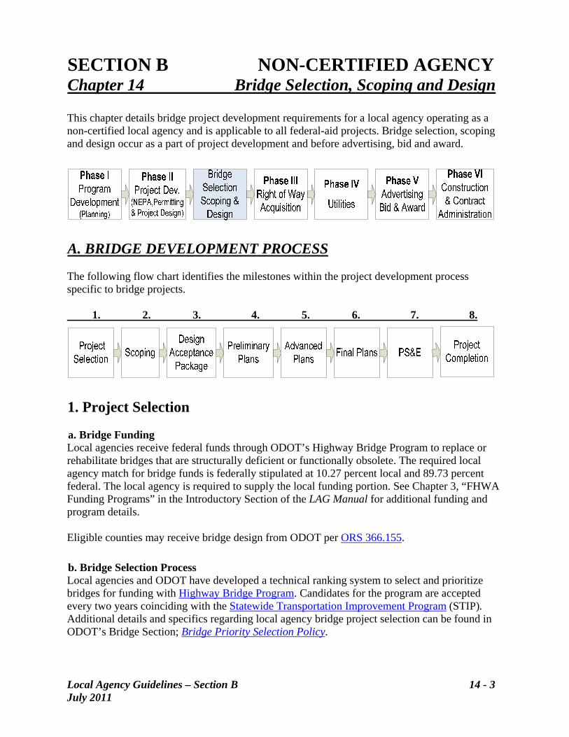
SECTION B NON-CERTIFIED AGENCY Chapter 14 Bridge Selection, Scoping and Design This chapter details bridge project development requirements for a local agency operating as a non-certified local agency and is applicable to all federal-aid projects. Bridge selection, scoping and design occur as a part of project development and before advertising, bid and award.
A. BRIDGE DEVELOPMENT PROCESS The following flow chart identifies the milestones within the project development process specific to bridge projects. 1. 2. 3. 4. 5. 6. 7. 8.
1. Project Selection a. Bridge Funding Local agencies receive federal funds through ODOT’s Highway Bridge Program to replace or rehabilitate bridges that are structurally deficient or functionally obsolete. The required local agency match for bridge funds is federally stipulated at 10.27 percent local and 89.73 percent federal. The local agency is required to supply the local funding portion. See Chapter 3, “FHWA Funding Programs” in the Introductory Section of the LAG Manual for additional funding and program details.
Eligible counties may receive bridge design from ODOT per ORS 366.155.
b. Bridge Selection Process Local agencies and ODOT have developed a technical ranking system to select and prioritize bridges for funding with Highway Bridge Program. Candidates for the program are accepted every two years coinciding with the Statewide Transportation Improvement Program (STIP). Additional details and specifics regarding local agency bridge project selection can be found in ODOT’s Bridge Section; Bridge Priority Selection Policy.
Local Agency Guidelines – Section B 14 - 3 July 2011

Local Agency Guidelines – Section B 14 - 4 July 2011
Candidate bridge replacement projects in the small bridge category submitted by local agencies to ODOT will be evaluated under the direction of the Local Agency Bridge Selection Committee (LABSC) before being prioritized with a technical ranking system. Candidate bridge rehabilitation projects in the small bridge category and bridges in the large bridge category are evaluated individually without using the technical ranking system. After the technical review, bridge projects will be prioritized, scoped and then programmed in priority order, to the limits of available funding and placed in the STIP. For additional information on the Local Agency Bridge Selection Committee, see STIP Users Guide, Chapter VI (Program Descriptions). Exception to the above selection process is as follows: c. Emergency Exceptions In the event a bridge has been destroyed or substantially damaged causing an emergency situation, and no other state or federal funds are available for its replacement or restoration, the local agency may apply for Highway Bridge Program funds to have the bridge replaced or restored. If the emergency request is approved, another project may have to be delayed by adding this project. The failed or damaged structure will be given a new Sufficiency Rating to reflect its new condition. A new technical ranking will be calculated, using the recalculated Sufficiency Rating. If the emergency structure has a lower priority than currently scheduled projects, the emergency funding will be denied. If the failed or damaged structure has 30,000 square feet of deck area or greater, the bridge will be evaluated and a funding strategy recommended by the Bridge Selection Review Committee.
2. Scoping The scoping effort builds upon the information provided by the local agency in its project application. Scoping is the process of defining the parameters of the project and the level of effort required in the various project delivery phases. Scoping will be performed using an ODOT Local Program scoping team. The scoping team may consist of staff from the following entities:
ODOT Local Government Section staff ODOT Regional staff Consultant Local agency staff
In addition to this staff, it is recommended that other appropriate personnel participate on the scoping team to provide needed information regarding roadway design, environmental, right of way, utilities, railroads, land survey, bridge foundation, hydraulics, and structural issues. Scoping can be done by meeting with the assigned project personnel and specialists in the field at the site, or in the office, if sufficient data is available. ODOT and the scoping consultant
Local Agency Guidelines – Section B 14 - 5 July 2011
coordinate a field review in consultation with local agency and the Regional Local Agency Liaison. The field review provides the initial project data and information needed to program the project in the STIP. It also guides the Project Development Team to the successful production of the Plans, Specification & Estimate (PS&E). Additional information regarding PS&E is available in Section B, Chapter 11, PS&E. It is recommended that the scoping process be documented by a bridge scoping package, as described below. a. Bridge Scoping Package The scoping team is responsible for developing a draft scoping package. ODOT’s Office of Project Delivery’s Project Scoping Best Practices Guidebook describes the processes and procedures for scoping bridge projects. On the Local Government Section’s website, a scoping checklist is available under the document entitled “Scoping Notes.” The draft scoping package at a minimum will include the following:
The names and roles of the teams’ members throughout the project (if known). Outside agency involvement. Decisions regarding site investigation and analysis procedures for
o geometric design elements o foundations o hydraulics o structures o right of way o environment o traffic o utilities o permits
Preliminary discussion of alternative designs and establishment of the project limits. “Scoping Notes” Discussion of funding and who will perform project development, advertisement, award
and administration of construction. Desired project schedule. A detailed break-down of the cost for all phases of work.
The scoping team will supply the draft scoping package for each bridge scoped to the following for review and comment:
ODOT’s Local Government Section The local agency The Regional Local Agency Liaison ODOT Bridge Section
The scoping team collects comments from all parties involved. The comments are incorporated into the final scoping package. Any disputes will be resolved through ODOT’s Local Government Section.
Local Agency Guidelines – Section B 14 - 6 July 2011
The scoping team delivers the final scoping package to ODOT’s Local Government Section. The Local Government Section will distribute the final scoping package so each involved entity and department has access to the package. b. Rehabilitating vs. Replacing Decisions On each project, a determination must be made as to whether an existing bridge should remain in place, be rehabilitated, or replaced. This decision should be based on an assessment of the structural and functional adequacy of the bridge for the type and volume of projected traffic over its design life. The determination for replacement should consider historic significance of the bridge as well as the technical difficulty and impact to integrity when attempting to bring an older structure up to existing standards. If the project impacts a bridge owned by the State of Oregon, coordination with ODOT will be required before any decision can be finalized to replace or modify a historically significant bridge using federal funds. For other federally-funded projects on structures owned by counties and other local governments, ODOT can provide coordination and recommendations for evaluation and regulatory compliance. i. Rehabilitated Bridges
Rehabilitated bridges should be designed to meet or exceed minimum standards as described previously in Section B.1 of this chapter. Exceptions to these standards may be approved based upon individual site evaluations; however, the rehabilitated bridges should, as a minimum, meet the design loading requirements of ODOT’s Bridge Design and Drafting Manual Section 1.1.7.2. Bridge rehabilitation projects must bring all major structural and safety features up to standards, as required for HBP funds. Substandard bridge rail should be upgraded to current standards. “Safety” curbs which can cause vehicles to vault, should be eliminated. Exceptions may be considered on a case-by-case basis if safety can be adequately enhanced for the intended use. Cost-effective considerations may prevent full widening or full upgrading of the bridge rail. Also, if the structure is listed on or determined eligible for the National Register of Historic Places, exceptions may be considered. When a decision is made to retain a bridge, the bridge rail should be evaluated to determine if it can adequately contain and redirect vehicles without snagging, penetrating, or vaulting. Consideration should be given to upgrading structurally inadequate or functionally obsolete bridge rail. The evaluation should be based upon criteria similar to that shown in the National Cooperative Highway Research Program’s NCHRP Report 350, “Multiple-Service-Level Highway Bridge Railing Selection Procedures.” Guidance concerning width, rail and geometric criteria tradeoffs and the effects on safety are contained in NCHRP’s Research Digest 98 and Report 203 both entitled “Safety at Narrow Bridges” as noted in FHWA’s Federal–Aid Policy Guide – Non-Regulatory Supplement.
ii. Bridge Replacement
Bridge replacement projects should meet or exceed minimum standards as described previously in Section B.1 of this chapter. In the case of bridges on low volume roads and streets, exceptions may be appropriate if the existing road will not be upgraded in the foreseeable future (typically 20 years or more).
iii. Bridges Classed As Non-Deficient Or Non-Functionally Obsolete
Bridges which have been strengthened or rehabilitated to eliminate deficiencies are to be reclassified as non-deficient in the bridge inventory. Those existing bridges for which FHWA
Local Agency Guidelines – Section B 14 - 7 July 2011
has approved an exception to the AASHTO standards are also to be reclassified as non-deficient since it was determined that the bridge is adequate for the type and volume of projected traffic over its remaining design life. If exceptions were granted as a temporary measure because of a scheduled future replacement project, the bridge may remain classified as deficient.
c. Historic Bridge Coordination Procedures The following are general guidelines for the treatment of existing bridges, bridge replacement and bridge rehabilitation projects for bridges 50 years or older. For bridges that are 50 years old or older, a determination of historic eligibility is required to be listed on the National Historic Register. Eligibility criteria is available at the National Register of Historic Places website. i. National Historic Preservation Act
Bridges which have been listed on, determined eligible for or are considered potentially eligible for the National Register of Historic Places, should meet the following environmental requirements provided in Section 106 of the National Historic Preservation Act of 1966. Section 106 Report requires that a determination be made regarding whether there are any National Register listed or eligible properties within the project area and the effect the proposed project will have on these properties. A local agency with a bridge project affecting a historically significant structure should contact ODOT’s Regional Local Agency Liaison who will coordinate with ODOT’s Cultural Resources staff. This process, as outlined below, includes obtaining ODOT’s concurrence on eligibility and level of effect prior to requesting a determination from the State Historic Preservation Office.
STEP 1:The Regional Local Agency Liaison will forward the Determination of Eligibility form and Cultural Resource Report to ODOT Cultural Resources staff, who will review and forward this documentation to the State Historic Preservation Office for concurrence. STEP 2:If a property is on or eligible for the National Register of Historic Places, then the Criteria of Adverse Effect will be applied. The Regional Local Agency Liaison will forward the Finding of Effect to ODOT’s Cultural Resources staff, who will review and forward this documentation to State Historic Preservation Office for concurrence. The Finding of Effect and other related forms can be found in ODOT’s Cultural Resources Manual. If the project will have an Adverse Affect on historic properties, the Finding of Effect must indicate alternatives considered that avoid, minimize, or mitigate effects to historic properties. STEP 3: If the project will have an Adverse Affect on historic properties, contact the Regional Local Agency Liaison who will coordinate with the local agency for the development of a Memorandum of Agreement with the Advisory Council, State Historic Preservation Office, ODOT and FHWA. The Memorandum of Agreement will include measures to mitigate the adverse effects on a resource prior to final environmental document preparation. STEP 4: Projects which involve right of way acquisition or excavation have potential to uncover archaeological or historical resources. Under these conditions, an archaeological survey or archaeological clearance letter must be completed. For information on
Local Agency Guidelines – Section B 14 - 8 July 2011
archaeological surveys, contact the Regional Local Agency Liaison who will coordinate with ODOT’s Geo-Environmental staff.
ii. Section 4(f) Section 4(f) requirements may apply if the proposed project will adversely affect the historic integrity of the National Register or register eligible property. When a Section 4(f) Evaluation is required, the Section 106 Report and Draft Section 4(f) Evaluation will be prepared separately to satisfy the requirements of both laws. For further details, see Section B Chapter 5, Environmental Processes within this LAG Manual. Local agencies are to send Section 4(f) Evaluations to the Regional Local Agency Liaison who will coordinate with ODOT’s Cultural Resources staff to review and forward this documentation to FHWA for approval.
iii. Design Considerations Consideration should be given to design standard exceptions for railing replacements, roadway widths, etc., when the structure is listed on or determined eligible for the National Register of Historic Places according to the criteria in ODOT’s Bridge Design and Drafting Manual.
For additional information contact the Regional Local Agency Liaison, or refer to ODOT’s Cultural Resoures website, ODOT’s Covered Bridge website and FHWA’s Covered Bridge Manual.
3. Design Acceptance Package (DAP) The Design Acceptance Package is a critical milestone of the decision-making process that establishes the geometric boundaries of the project footprint, and provides for a more reliable update to the project scope, schedule, and budget. Design acceptance occurs at the end of the initial design phase and requires all project disciplines to review the design for balance of context with standards and policies. At this time, technical and non-technical stakeholders review design elements according to their specific interest. a. Type, Size & Location (TS&L) Design Package The TS&L Design Package is part of the Design Acceptance Package, see Section B, Chapter 10, Design Approval, of this LAG Manual for further details. The TS&L design package shall include:
TS&L Plan and Elevation drawing TS&L Estimate of structure construction cost TS&L Narrative, including a discussion of the bridge alternative study TS&L Geotechnical Report Draft Hydraulics Reports A list of anticipated design exceptions or design deviations required for the execution of
the project. The above items should be prepared in accordance with:
Local Agency Guidelines – Section B 14 - 9 July 2011
ODOT’s Bridge Design and Drafting Manual Section 1.1.2.11 Type, Size, and Location (TS&L) Design, and Section 2.6 Type, Size and Location Plan & Elevation.
ODOT’s Geotechnical Design Manual for TS&L Foundation Design Memo. ODOT’s Hydraulics Manual for Draft Hydraulics Report.
The plans as submitted for review should be prepared in such a manner that when reduced to half size (11 inches by 17 inches) all notes and details will be legible. All contract documents shall be prepared in English units. Additional information, refer to ODOT’s Bridge Engineering Section’s Bridge Design and Drafting Manual, Section 2.6 Type, Size and Location Plan and Elevation for the check-list. ODOT reviewers will ensure that local agency plans, details and specifications are legible and that the work is constructible. With ODOT approval, the plans, details and specifications are not required to be written or shown in precisely the same manner as ODOT-prepared documents. b. Bridge Alternatives Study Typically, up to three bridge structure-type alternatives are investigated, prior to completion of Type, Size & Location (TS&L) Design Package. The available foundation and hydraulics information is used to develop the appropriate structure-type alternatives. Preliminary square foot cost estimates are developed for the bridge using historical cost data. In some cases, it may be useful to develop sketches for the bridge alternatives. ODOT and the local agency will discuss advantages, disadvantages, and cost estimates for each, and the recommended alternative. The preferred alternative is presented in the TS&L Report. c. Type, Size and Location Study for Major or Unusual Structures For bridge replacement projects of a major or “unusual” structure, FHWA requires a local agency to conduct a more detailed Type Size & Location Report. Factors which constitute “unusual” site conditions are defined in ODOT’s Bridge Engineering Section’s Bridge Design and Drafting Manual, Section 1.1.2.10 Special Considerations for Federal-aid Projects, Unusual Structures.
4. Preliminary Plan Package Preliminary Plans is for technical staff to provide comments and feedback on the adequacy and appropriateness of the bridge design with regard to the standards described under the “Bridge Design Standards” section of this chapter and the project needs. Preliminary Plans Review Package shall include:
Preliminary Bridge Plans Preliminary Cost Estimates Final Foundations Report Final Hydraulics Report
The above items should be prepared in accordance with:
ODOT’s Bridge Design and Drafting Manual Geotechnical Design Manual for Final Foundation Report
Local Agency Guidelines – Section B 14 - 10 July 2011
Hydraulics Manual
5. Advance Plans Advanced Plans Package is a key interim step of the contract document phase and requires all project disciplines to review draft contract documents for completeness and accuracy. It is for technical staff to provide quality control review of the project plans, specifications, and estimates as a package. a. Advanced Plans Review Package The Advanced Plans Review Package shall include:
Advanced Bridge Plans Advanced Bridge Construction Cost Estimate Advanced Construction Standard Specifications and Special Provisions
b. Quality Control/Quality Assurance A Class I check will be performed on the advance plans, specifications and estimates, as described in ODOT’s Bridge Engineering Section’s Bridge Design and Drafting Manual at Section 1.1.2.12. A Class II check will be considered based on the complexity of the bridge project, per BDDM Section 1.1.2.12. At this point, foundation and hydraulics engineers will review the final plans and specifications for conformance with the report recommendations.
6. Final Plans Package This step occurs in follow-up to review and comment on the advanced plans, and specifications, and cost estimate. It is the last opportunity for contract documents to be reviewed by technical staff for quality control and document completeness, before the project is ready to move forward for FHWA review (when needed) and PS&E submittal. Based on the comments provided during the Advanced Plans review, the draft contract documents are advanced to the final plans. The Final Plans Review Package shall include:
Final Bridge Plans Final Bridge Construction Cost Estimate and Final Construction Standard Specifications and Special Provisions
7. Plans, Specifications and Estimates (PS&E) This point of decision-making provides certainty of the completeness of a project for bid. Decision-making with any desired interim milestones between Design Acceptance and PS&E Submittal (e.g., TS&L, Advanced, and Final Plans) should be addressed through individual Quality Control Plans and Project Development Change Requests as needed. For information regarding PS&E submittals, refer to Chapter 11, in Section B of this LAG Manual.
8. Project Completion
Local Agency Guidelines – Section B 14 - 11 July 2011
Local agencies shall submit to ODOT all as-built bridge drawings, pile records, foundation reports, hydraulics reports, and a PE stamped load rating report for all National Bridge Inventory structures. This information must be submitted to ODOT no later than 60 days after the bridge is open to traffic. As-built bridge drawings shall be in accordance with the Bridge Design and Drafting Manual, Section 2. Bridges designed using the AASHTO Load Resistance Factor Design (LRFD) Bridge Design Specifications will be load rated using the AASHTO Guide Manual for Condition Evaluation and Load and Resistance Factor Rating (LRFR) of Highway Bridges and the ODOT LRFR Manual (Tier 2). Documentation of the completed load ratings, including electronic files, will be consistent with the requirements contained in the ODOT LRFR Manual (Tier-2). B. BRIDGE DESIGN, PRACTICE AND POLICIES
1. Bridge Design and Standards Design standards for bridge projects on the National Highway System (NHS) and the Oregon State Highway System shall be in compliance with the standards specified in the current AASHTO LRFD Bridge Design Specification, AASHTO guide specifications for highway bridges, and related references as well as the following ODOT manuals:
Bridge Design and Drafting Manual
Geotechnical Design Manual
Hydraulics Manual
a. Bridge Design and Standards For Non-Highway System Design standards for bridge projects on the non-National Highway System and the Local Agency Road System shall be in compliance with the standards specified in the current AASHTO LRFD Bridge Design Specification, AASHTO guide specifications for highway bridges, and related references as well as the ODOT manuals listed above except as modified by this section:
BDDM Section 1.1.2.7 “Bridge End Panels and Supports” is modified as follows:
Add the following: End panels may be deleted under certain unique conditions. A geotechnical and structural evaluation is required for considering the deletion of end panels and approval of a deviation from ODOT Senior Local Bridge Standards Engineer. The final decision on whether or not to delete end panels shall be made by the ODOT’s Senior Local Bridge Standards Engineer with consideration to the geotechnical and structural evaluation.
Design all bridge components for full seismic loading according to the 1st edition of AASHTO Guide Specifications for LRFD Seismic Bridge Design, except as modified in ODOT’s Bridge Design and Drafting Manual 1.1.10.2-1 _ General Considerations as follows:
Local Agency Guidelines – Section B 14 - 12 July 2011
Replace item 2) beginning “500-year “Serviceable”…” with the following: 2) Design to the 1000 year criteria.
1.1.10.3 Applications of AASHTO Guide Specifications for LRFD Seismic Bridge Design 1.1.10.3-1 General Considerations is modified as follows:
Replace item 2) beginning “500-year “Serviceable”…” with the following: 2) Design to the 1000 year no collapse criteria.
2. Deviations/Design Exception Process Deviations and design exceptions from the Bridge Design Standards identified in Section B.1 of this Chapter, and the standards identified in Chapter 9, General Design, Section B of this LAG Manual, require approval of a Local Agency Design Exception Request from ODOT. The deviation and design exception process is described in Chapter 9, General Design, Section B of this LAG Manual.
3. Proprietary or Patented Products FHWA does not allow the use of proprietary or patented products, processes, or specifications on local agency projects unless the following approved item:
Is purchased or obtained through competitive bidding with equally suitable unpatented items. Is essential for synchronization with an existing system. Is used for research. Is used for a special type of construction. Is used in a relatively short section of the project.
Such usage must be documented in a Public Interest Finding by the local agency and approved by the appropriate agency as identified in the Approval Authority Matrix, Appendix A-2, of this Manual. Additional guidance on the use of proprietary items or patented products can be found in ODOT’s Bridge Engineering Section’s Bridge Design and Drafting Manual, Section 1.1.2.10(4).
4. Value Engineering Study Bridge projects over $25 million must include a Value Engineering Study during the design phase. See Chapter 9, General Design in Section B of this LAG Manual for additional information about Value Engineering.
5. Approach Guard Rail and Bridge Rail On all projects involving bridges, the approach guard rail should be evaluated and upgraded to current standards. Approach guard rail, if warranted, must be properly anchored to the bridge. The transition between the approach guard rail and the bridge rail should be smooth and of sufficient strength (i.e., reduced post spacing) to prevent snags and vehicle pocketing. Consideration should be given to design standard exceptions where safety can be adequately
enhanced for the intended use and when the structure is listed on or determined eligible for the National Register of Historic Places. Bridge rail designs for new and reconstructed bridges shall have been successfully crash tested and adopted as an ODOT standard or approved by ODOT according to ODOT’s Bridge Design and Drafting Manual, which contains specific requirements relating to railings on historic bridges.
6. Foundation Design Bridge foundation design standards may be found in ODOT’s Geotechnical Design Manual, which is available on ODOT’s Geo-Environmental website. This manual establishes ODOT standards for all aspects of foundation design including site reconnaissance (scoping), office research, field investigations, foundation selection and design, and seismic design. Provide information in the final Geotechnical Report. ODOT foundation design methods generally follow those described in AASHTO LRFD Bridge Design Specifications. a. Foundation Investigation The level of foundation investigation for a specific project will require careful consideration by the geotechnical engineer and appropriate members of the project development team. Some guidelines which will aid the team in their determination are as follows.
Exposed bedrock can reduce the need for extensive investigation unless the structure is
unusually large or part of a critical road network. For certain structures, the quality of the rock and its consistency at depth will be required.
Single span bridges can typically accommodate settlement, such as differential settlement,
better than multiple span bridges. Although settlement must be considered, there may be less need for extensive settlement prediction methods depending on the foundation conditions and the performance requirements of the structure.
The cost-benefit of extensive subsurface exploration may be reduced somewhat on projects
with small, relatively low cost bridges. When very small foundations are needed, construction cost overruns resulting from a lack of subsurface information may also be small. On small projects, an assessment may be made to compare and balance the costs of a standard exploration program with the potential consequences and cost impacts that could occur during construction due to a lack of sufficient foundation information.
NOTE: The value of an experienced foundation specialist is critical even on a small bridge project. This is because a large error in the constructability of even a small foundation can occasionally result in an extremely costly “fix” during construction.
In areas where the geologic model is well known from previous investigation and is known to be very consistent, the need for additional exploration may be reduced to that sufficient for confirmation of the expected profile.
Local Agency Guidelines – Section B 14 - 13 July 2011
Local Agency Guidelines – Section B 14 - 14 July 2011
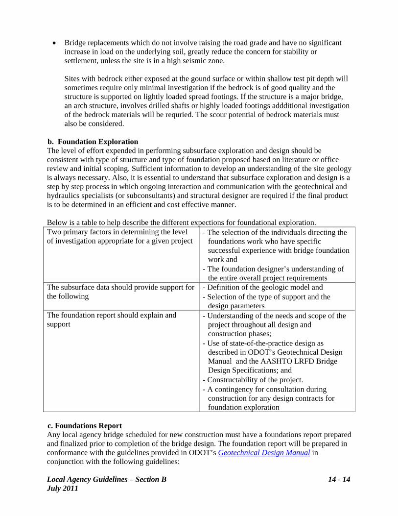
Bridge replacements which do not involve raising the road grade and have no significant increase in load on the underlying soil, greatly reduce the concern for stability or settlement, unless the site is in a high seismic zone. Sites with bedrock either exposed at the gound surface or within shallow test pit depth will sometimes require only minimal investigation if the bedrock is of good quality and the structure is supported on lightly loaded spread footings. If the structure is a major bridge, an arch structure, involves drilled shafts or highly loaded footings addditional investigation of the bedrock materials will be requried. The scour potential of bedrock materials must also be considered.
b. Foundation Exploration The level of effort expended in performing subsurface exploration and design should be consistent with type of structure and type of foundation proposed based on literature or office review and initial scoping. Sufficient information to develop an understanding of the site geology is always necessary. Also, it is essential to understand that subsurface exploration and design is a step by step process in which ongoing interaction and communication with the geotechnical and hydraulics specialists (or subconsultants) and structural designer are required if the final product is to be determined in an efficient and cost effective manner.
Below is a table to help describe the different expections for foundational exploration. Two primary factors in determining the level of investigation appropriate for a given project
- The selection of the individuals directing the foundations work who have specific successful experience with bridge foundation work and
- The foundation designer’s understanding of the entire overall project requirements
The subsurface data should provide support for the following
- Definition of the geologic model and - Selection of the type of support and the
design parameters The foundation report should explain and support
- Understanding of the needs and scope of the project throughout all design and construction phases;
- Use of state-of-the-practice design as described in ODOT’s Geotechnical Design Manual and the AASHTO LRFD Bridge Design Specifications; and
- Constructability of the project. - A contingency for consultation during
construction for any design contracts for foundation exploration
c. Foundations Report Any local agency bridge scheduled for new construction must have a foundations report prepared and finalized prior to completion of the bridge design. The foundation report will be prepared in conformance with the guidelines provided in ODOT’s Geotechnical Design Manual in conjunction with the following guidelines:
The foundation report contains information needed by the structural designer to understand the site conditions, complete the foundation design and provide specifications as needed for the project and address construction situations. The report is based on an understanding of the overall project requirements. The foundation report is written and finalized after interaction with the structural designer which leads to a proposed foundation design and the Type Size & Location plan and narrative. The report should also demonstrate good project understanding. In addition to foundation recommendations, it includes a brief description of reasonable alternative designs and the reasons why the recommended alternate was selected. Alternatives may be eliminated when believed to be impractical, without detailed analysis, or appropriate for the site conditions and structure type.
A Foundation Data Sheet is part of the bridge plans for all bridge projects that include any subsurface exploration work such as test borings or test pits.
NOTE: OREGON BRIDGES WITH “UNKNOWN” FOUNDATIONS As of November 2006, there are approximately 4,000 local agency bridges in Oregon. Approximately 2,400 of these bridges are coded as scour critical. Of the scour critical bridges approximately 1,600 bridges are coded as a “U” meaning that the foundations are unknown. Forty percent of all local agency bridges have unknown foundations. Without foundation data the bridges cannot be evaluated for scour potential or inspected effectively as the substructure cannot be evaluated with accuracy. There is not enough data and sufficient historical records to determine foundation or hydraulic data for these bridges with unknown foundations.
d. ODOT Review Effort ODOT’s Geotechnical Design Manual provides guidelines for the review of foundation reports. A checklist is provided to aid in the review process. However, it is understood that not every guideline within the Geotechnical Design Manual applies to each project. The consultant’s report should state that the items were either not applicable or have been resolved, either by engineering judgment, site inspection, or by analysis. In the review process, ODOT engineers will normally base their comments on the data presented in the consultants documents. If the basis for a design element is not clearly stated or resolved, a question or comment may be given. ODOT will clearly indicate whether comments are informational, or are requirements which affect legal, safety, or significant economic issues. The geotechnical designer should remain involved throughout project development and should also review and comment on both the Type Size & Location and final plans and specifications. ODOT requires that consultants use sound engineering judgment in establishing the approach and scope of geotechnical work. Some latitude will be allowed in the degree of documentation if the selected foundation is believed to be practical, safe and cost-effective.
7. Hydraulic Investigation Guidelines a. Overall Hydraulic Design
Local Agency Guidelines – Section B 14 - 15 July 2011
Local Agency Guidelines – Section B 14 - 16 July 2011
ODOT’s Bridge and Geo/Environmental Sections and FHWA require that the structure not wash out or suffer significant damage or failure during a 500-year flood event. Local agencies should use ODOT’s Hydraulics Manual along with the guidelines depicted in Appendix A of this chapter, “Bridge Hydraulics Performance Specification.” b. Hydraulics Report The hydraulics report contains information needed by the structural designer to understand the site conditions, complete the bridge opening design and address construction situations. The report is based on an understanding of the entire, overall project requirements. The hydraulics report is written and finalized after interaction with the structural designer, roadway designer, foundation designer, environmental specialists and regulatory agencies. This process leads to a proposed hydraulic opening, scour provisions and the Type Size & Location report and narrative. In addition to the bridge opening recommendations, the hydraulics report also includes a description of reasonable alternative designs and the reasons why the recommended alternate was selected. A draft hydraulics design shall be submitted to identify hydrologic factors and parameters that will effect the selection of the structure. The study must be detailed enough so that the proposed structures layout and type can be identified. The draft Hydraulic report will need to be submitted in time to be used in the TS & L phase of the project. The hydraulics information, along with the foundations information are key components for determining the scour risk for the structure. An engineer with a hydraulics specialty should remain involved throughout project development. The hydraulics engineer should review and comment on both the Type Size & Location and preliminary PS&E documents. Contracts should also include a contingency for consultation during construction if there are unusual circumstances or problems involving rip rap placement or other special features. The designer or project manager shall submit the Hydraulics Report with the Temporary Water Management Plan to the Agency for review and comment prior to the start of construction of project elements effecting drainage. The final Hydraulics Report will include all supporting analysis and drawings. A CD with all pertinent data used to run the computer model as well as contour mapping depicting cross section locations used to generate the computer model, shall be kept on file and submitted as requested by ODOT . A temporary Water Management Plan shall be submitted. When a bridge project is in the Federal Emergency Management Agency (FEMA) floodway, provide a 100-year no-rise certification to the regulatory agency. c. ODOT Review Effort The guidelines in Appendix A at the end of this chapter, are intended to be a comprehensive representation of areas with possible applicability. However, it is understood that not every item applies to each project. The engineer’s report should state that the items were either not applicable or have been resolved, either by engineering judgment, site inspection, or by analysis.

Local Agency Guidelines – Section B 14 - 17 July 2011
In the review process, ODOT engineers will normally base their comments on the data presented in the engineer’s documents. If the basis for a design element is not clearly stated or resolved, a question or comment may be given. ODOT will clearly indicate whether comments are informational, or are requirements which affect legal, safety, or significant economic issues. Communication between ODOT and the engineer is encouraged during project development.
Local Agency Guidelines – Section B 14 - 18 July 2011
SECTION B NON-CERTIFIED AGENCY Chapter 14 Appendix A Bridge Hydraulics Performance Specification A. SCOPE This work consists of performing all of the necessary site investigation, surveying, hydrologic and hydraulic calculations, design and drawings for bridge replacement, rehabilitation, or repair. The findings of this work will be clearly summarized in a hydraulics report.
1. Hydraulics Report The hydraulics report will include hydraulic data on the existing structure and provide comparison with proposed alternative bridge designs. The report will:
Provide design data on the existing bridge condition and proposed bridge design alternatives.
Address the possible long term effects of channel aggradation/degradation. Discuss the effects of lateral channel migration. Summarize any parole evidence gathered about past conditions at this site. Provide a temporary water management plan. Address environmental concerns and furnish information needed for applicable permits
or jurisdictional requirements, such as, no-rise certifications in FEMA floodways or floodway revisions.
Design calculations and supporting drawings will be provided to clarify the findings stated in the report.
2. Designer’s Performance Parameters The designer shall perform all investigation, design, drafting and calculations needed to produce the hydraulics design. The designer shall perform all design in accordance with all applicable standards, manuals, procedures and laws. The designer shall coordinate with ODOT staff, FHWA, FEMA, contractors and other agencies as necessary to acquire project related reports and information, and resolve questions, comments and information inquiries. The designer shall be a Registered Professional Engineer licensed in the State of Oregon and shall affix his seal and signature to the hydraulics report.
B. APPLICABLE STANDARDS AND REFERENCES The hydraulic design shall be in accordance with this Performance Specification and the relevant requirements of the following Standards and References, unless otherwise stipulated in this specification. Standards and References specifically cited in the body of the specification establish requirements that shall have precedence over all others. Should the requirements in any
Local Agency Guidelines – Section B 14 - 19 July 2011
reference conflict with those in another, the reference highest on the Standard or Reference list shall govern. It is the designer’s responsibility to obtain clarification of any unresolved ambiguity prior to proceeding with design or construction. Questions regarding the interpretation of ODOT’s Hydraulics Manual and other publications shall be directed to the Sr. Local Bridge Standards Engineer.
1. ODOT Publications
ODOT’s Hydraulics Manual Oregon Standard Specifications for Construction ODOT’s Bridge Section, Bridge Design Drafting Manual
2. FHWA Publications
FHWA, HDS-6, River Engineering for Highway Encroachments FHWA, HEC-18, Evaluating Scour at Bridges FHWA, HEC-20, Stream Stability at Highway Structures FHWA, HEC-11, Design of Riprap Revetment FHWA, Federal-Aid Policy Guide, 23 CFR 650A, Location and Hydraulic Design of
Encroachments on Flood Plains FHWA, TS-84-204, Guide for Selecting Manning’s Roughness Coefficients for Natural
Channels and Flood Plains FHWA, HEC-25, Tidal Hydrology, Hydraulics and Scour at Bridges FHWA, HEC-23, Bridge Scour and Stream Instability Countermeasures FHWA, HEC-21, Design of Bridge Deck Drains FHWA, HEC-9, Debris Control Structures FHWA, HDS-2, Highway Hydrology FHWA, HEC-22, Urban Drainage Design Manual FHWA, HDS-5, Hydraulic Design of Highway Culverts FHWA, HEC-15, Design of Roadside Channels with Flexible Lining FHWA, HEC-14, Hydraulic Design of Energy Dissipaters for Culverts and Channels
3. AASHTO Publications
AASHTO Manual for Highway Drainage Guidelines
It is the responsibility of the designer to become familiar with these Standards and determine which are appropriate.
4. Additional References ODOT’s Qualified Products List ‘As Constructed’ Bridge Drawings Bridge Inspection Reports Bridge Structure and Inventory Appraisal Report
Local Agency Guidelines – Section B 14 - 20 July 2011
National Flood Insurance Program Regulations contained in Title 44, Chapter 1 of the Code of Federal Regulations
ODOT’s Standard Drawings NCHRP Project 24-19 Environmentally Sensitive Channel and Bank Protection Measures Other NCHRP publications as applicable
5. Methodology and Reports a. Hydrology Methodology Three common methods of calculated flood flows are described in ODOT’s Hydraulics Manual along with additional information on each method. The methods are:
Flood Insurance Study Data. Gaging Station Data. US Geological Survey Regression Equation; and in very limited situations. Local Regional Methods.
The calculated flows shall be in agreement with eye-witness testimony and parole evidence gathered from historical records. If ice and/or debris passage are a concern the proposed structure designs must address how these problems will be managed. b. Hydrological Report Provide the flood flows expected at the site and the recurrence intervals for these flows. The report should include, but is not limited to the:
Sources of flooding. Contributing drainage area at the site. Time of year when floods usually occur. Method used to determine the hydrology. Flood recurrence interval versus peak discharge relationship at the site. (The 2-year, 5-
year, 10-year, 25-year, 50-year, 100-year and 500-year flows should be calculated. The roadway overtopping flood will also need to be calculated if its recurrence interval is
less than the 500-year flooding event). Design flood recurrence interval can be determined from ODOT’s Hydraulics Manual,
Chapter 3 and Table 3-1.
6. Hydraulic Design a. Waterway Opening Design The criteria used to size the waterway opening of the proposed structure should be described in the reports. Freeboard recommendations are provided in ODOT’s Hydraulics Manual. The backwater created by the proposed structure should not exceed that of the existing structure. If additional backwater is created, a justification must be submitted explaining the effects of the increased flooding on the site and what liability the local agency may incur by causing a rise in water surface elevations on the surrounding community. If the rise is proposed for a regulated
Local Agency Guidelines – Section B 14 - 21 July 2011
FEMA floodway, the designer must obtain approval from ODOT’s GeoHydro Unit in accordance with their exception process before proceeding. Any rise in the floodway will require permission from the local land use authority. The process takes a considerable amount of time and engineering cost, so it must be addressed as soon as possible. If a channel modification is proposed, a justification on why the change is needed and how it will be maintained for the life of the bridge shall be submitted. The hydraulic design should be presented using a combination of drawings, hydraulic data sheets and written narrative. The waterway openings of the existing and proposed bridge designs shall be shown in the accompanying drawings to the hydraulics report. The report shall include the following:
A description of the existing bridge and drainage area. The design flood, base flood and maximum flood data and the roadway overtopping
flood (if applicable). The skew of the bridge to the stream flow. The water surface elevation at the downstream, upstream and at the approach section
of the bridge during the design flood. The width and area of the waterway at the downstream face of the bridge during the
design flood. The average velocity at the downstream face of the bridge opening during the design
flood. The narrative for the proposed bridge will typically include the following information:
The minimum recommended bottom of beam elevation. The types of abutments (vertical and spillthrough), end slopes, waterway area and
opening (If the bridge is skewed, it should be noted whether these dimensions are normal to channel centerline or parallel to the roadway centerline).
The number and type of piers. The bottom of beam elevation should be listed if the bridge is in pressure flow during
the design flood. b. Scour This section of the report presents the results of analyses on possible long term changes in channel geometry due to either aggradation or degradation, possible shifts in channel alignment due to lateral instability, clear-water or live-bed contraction scour, local scour and pier scour. The methods and assumptions used to determine potential scour elevations shall be stated and any past problems with aggradation, degradation, lateral stability, debris, ice, or scour discussed. Scour depths are calculated for the following floods:
Scour depths during the overtopping flood are analyzed if the roadway overtopping flood recurrence interval is less then the recurrence interval for the 100-year flood.
Local Agency Guidelines – Section B 14 - 22 July 2011
Scour depths during the 100-year and overtopping floods are analyzed if the roadway overtopping flood recurrence interval is greater then the recurrence interval for the 100-year flood, but less than the recurrence interval for the 500-year recurrence interval flood.
Scour depths during the 100-year and 500-year floods are analyzed if the roadway
overtopping flood recurrence interval is greater then the recurrence interval for the 500-year flood.
Potential scour depths are calculated in accordance with procedures in HEC-18 as modified by ODOT’s scour guidelines within the Hydraulics Manual. c. Revetment Design The hydraulics design shall recommend revetment protection in the bridge waterway opening and embankment surrounding the abutments. The waterway opening and surrounding embankment is considered a scour critical zone. A scour critical zone is defined as the area within and outside of the bridge opening where any failure will cause a high potential for loss of human life. The methods given in HEC-11, supplemented and modified by the requirements stated in ODOT’s Hydraulics Manual shall be used to provide protection for the bridge abutments and surrounding embankments. The revetment is sized for the flood which creates the greatest scour potential. Environmental concerns will be addressed for the bridge site depending on the requirements of the environmental agencies. There is an industry concern about the longevity and strength of so-called “green” methods used under the conditions of the design and larger floods. The design criteria of HEC-11 will take precedence over design methods based on so-called “green” vegetative solutions. The environmental design can be placed above the countersinked protective blanket. It is the designer’s responsibility to integrate the environmental design with conventional design such that the stability of the foundations of the bridge and the surrounding embankments will not be less stable than would be provided by conventional methods developed using the guidance of HEC-11 or a similar tractive-force based analysis. Refer to the discussion in HEC-23 volume 1, chapter 6, for guidance, implementation and applicability in the Hydraulics Manual. All abutments and piers shall be protected from flood events up to and including the 500-year recurrence interval flood. Pier rip rap is considered to be temporary protection for piers. If riprap must be used around piers, the analysis must show that the proposed bridge will maintain structural integrity during the flood with maximum scour potential. d. Hydraulic Data Sheets Hydraulic data sheets, examples of which are found in ODOT’s Hydraulics Manual, shall be included in the report and will clearly state the hydraulic data for the existing and proposed structures in such a way as they can be easily compared. e. Temporary Water Management Plan Chapter 17 of ODOT’s Hydraulics Manual provides information for the planning and design of Temporary Water Management. Temporary Water Management is water control and treatment
Local Agency Guidelines – Section B 14 - 23 July 2011
when facilities are built or repaired in the riparian zone. These control and treatment measures are temporary. They are typically installed just before construction and removed immediately thereafter. Report and documentation guidelines are discussed in Chapter 4 of ODOT’s Hydraulics Manual. The objective of Temporary Water Management is to provide for uninterrupted streamflow through the project site and is required by the permitting regulatory agencies. This continuous flow prevents the downstream channel from drying up and adversely affecting aquatic life. The report must evaluate and provide fish passage alternatives during predicted flow conditions to regulators for review and comment early in the design stage. f. Detour Structures If a detour is planned for the project, the report should have recommendations for the detour bridge or culvert. The data should include seasonal limitations, flow area of the structure and minimum elevation of the detour structure. A brief statement about the proposed location of the detour will need to be prepared. Other information about the detour may include a discussion of maintenance needs such as monitoring for debris or scour. The detour structure will need to conform to the Temporary Water Management Plan regarding fish passage. Refer to FEMA Region 10 guidelines for detour structure when crossing is located in a FEMA floodplain or floodway located in the Hydraulics Manual Chapter 3. g. Drawings The hydraulics report shall include drawings of the existing and proposed alternative bridges. Examples of the needed drawings can be found in ODOT’s Hydraulics Manual. For the existing bridge, information shall include:
Waterway area and waterway width during the design flood (typically this area is parallel to the roadway centerline with the pier area subtracted).
Profile of the existing bridge and ground line of the waterway opening. Recurrence interval and elevation of the design flood. Lowest bottom of beam elevation of the bridge.
For the proposed bridge, information should include the following:
The waterway area and waterway width during the design flood (typically this area is parallel to the roadway centerline with the pier area subtracted).
The proposed waterway opening and the existing ground line. The recurrence interval of the design flood. The elevation of the design flood at the downstream face of the bridge opening. Minimum recommended bottom of beam elevation. The revetment protection details. Potential scour elevations.

Local Agency Guidelines – Section B 14 - 24 July 2011
A description of the recommended waterway opening, including abutment end slopes, channel bottom elevation and channel bottom width (typically these dimensions are perpendicular to the channel centerline. If not, an explanation is needed).