Embed Size (px)
Citation preview
TABLE OF CONTENTS
1.0 INTRODUCTION . . . . . . . . . . . . . . . . . . . . . . . . . . . . . . . . . . . . . . . . . . . . . . . . . . . . . . . . .1
1.1 SYSTEM COVERAGE . . . . . . . . . . . . . . . . . . . . . . . . . . . . . . . . . . . . . . . . . . . . . . .11.2 SIX -STEP TROUBLESHOOTING PROCEDURE. . . . . . . . . . . . . . . . . . . . . . . . . .1
2.0 IDENTIFICATION OF SYSTEM . . . . . . . . . . . . . . . . . . . . . . . . . . . . . . . . . . . . . . . . . . . . .1
3.0 SYSTEM DESCRIPTION AND FUNCTIONAL OPERATION . . . . . . . . . . . . . . . . . . . . . .1
3.1 GENERAL DESCRIPTION . . . . . . . . . . . . . . . . . . . . . . . . . . . . . . . . . . . . . . . . . . . .13.2 FUNCTIONAL OPERATION . . . . . . . . . . . . . . . . . . . . . . . . . . . . . . . . . . . . . . . . . . .2
3.2.1 TRANSMISSION OPERATION AND SHIFT SCHEDULING ATVARIOUS OIL TEMPERATURES . . . . . . . . . . . . . . . . . . . . . . . . . . . . . . .3
3.2.2 LINE PRESSURE CONTROL. . . . . . . . . . . . . . . . . . . . . . . . . . . . . . . . . .43.2.3 DRIVE LEARN PROCEDURE . . . . . . . . . . . . . . . . . . . . . . . . . . . . . . . . .4
3.3 DIAGNOSTIC TROUBLE CODES . . . . . . . . . . . . . . . . . . . . . . . . . . . . . . . . . . . . . .63.3.1 HARD CODE . . . . . . . . . . . . . . . . . . . . . . . . . . . . . . . . . . . . . . . . . . . . . . .63.3.2 ONE TRIP FAILURES. . . . . . . . . . . . . . . . . . . . . . . . . . . . . . . . . . . . . . . .73.3.3 INTERMITTENT CODE. . . . . . . . . . . . . . . . . . . . . . . . . . . . . . . . . . . . . . .73.3.4 STARTS SINCE SET COUNTER. . . . . . . . . . . . . . . . . . . . . . . . . . . . . . .73.3.5 TROUBLE CODE ERASURE . . . . . . . . . . . . . . . . . . . . . . . . . . . . . . . . . .73.3.6 EATX DTC EVENT DATA . . . . . . . . . . . . . . . . . . . . . . . . . . . . . . . . . . . . .73.3.7 LIST OF DIAGNOSTIC TROUBLE CODES . . . . . . . . . . . . . . . . . . . . . .83.3.8 DTC DESCRIPTIONS . . . . . . . . . . . . . . . . . . . . . . . . . . . . . . . . . . . . . . . .93.3.9 LIST OF TRANSFER CASE CONTROL MODULE (TCCM)
DIAGNOSTIC TROUBLE CODES (DTC) . . . . . . . . . . . . . . . . . . . . . . .223.3.10 QUICK LEARN . . . . . . . . . . . . . . . . . . . . . . . . . . . . . . . . . . . . . . . . . . . .253.3.11 CLUTCH VOLUMES . . . . . . . . . . . . . . . . . . . . . . . . . . . . . . . . . . . . . . . .26
3.4 USING THE DRBIIIT . . . . . . . . . . . . . . . . . . . . . . . . . . . . . . . . . . . . . . . . . . . . . . . .263.5 DRBIIIT ERROR MESSAGES . . . . . . . . . . . . . . . . . . . . . . . . . . . . . . . . . . . . . . . .27
3.5.1 DRBIIIT DOES NOT POWER UP (BLANK SCREEN). . . . . . . . . . . . . .273.5.2 DISPLAY IS NOT VISIBLE . . . . . . . . . . . . . . . . . . . . . . . . . . . . . . . . . . .273.5.3 SOME DISPLAY ITEMS READ ‘‘---’’ . . . . . . . . . . . . . . . . . . . . . . . . . . .27
3.6 TRANSMISSION SIMULATOR (MILLER TOOL # 8333) AND ELECTRONICTRANSMISSION ADAPTER KIT (MILLER TOOL #8333-1A) . . . . . . . . . . . . . . 27
4.0 DISCLAIMERS, SAFETY, AND WARNINGS . . . . . . . . . . . . . . . . . . . . . . . . . . . . . . . . .27
4.1 DISCLAIMERS. . . . . . . . . . . . . . . . . . . . . . . . . . . . . . . . . . . . . . . . . . . . . . . . . . . . .274.2 SAFETY . . . . . . . . . . . . . . . . . . . . . . . . . . . . . . . . . . . . . . . . . . . . . . . . . . . . . . . . . .27
4.2.1 TECHNICIAN SAFETY INFORMATION . . . . . . . . . . . . . . . . . . . . . . . . .274.2.2 VEHICLE PREPARATION FOR TESTING. . . . . . . . . . . . . . . . . . . . . . .284.2.3 SERVICING SUB-ASSEMBLIES . . . . . . . . . . . . . . . . . . . . . . . . . . . . . .284.2.4 DRBIIIT SAFETY INFORMATION . . . . . . . . . . . . . . . . . . . . . . . . . . . . .28
4.3 WARNINGS . . . . . . . . . . . . . . . . . . . . . . . . . . . . . . . . . . . . . . . . . . . . . . . . . . . . . . .284.3.1 VEHICLE DAMAGE WARNINGS . . . . . . . . . . . . . . . . . . . . . . . . . . . . . .284.3.2 ROAD TESTING A COMPLAINT VEHICLE . . . . . . . . . . . . . . . . . . . . . .294.3.3 ELECTRONIC PINION FACTOR WARNINGS (IF APPLICABLE) . . . .294.4.4 BULLETINS AND RECALLS. . . . . . . . . . . . . . . . . . . . . . . . . . . . . . . . . .29
5.0 REQUIRED TOOLS AND EQUIPMENT . . . . . . . . . . . . . . . . . . . . . . . . . . . . . . . . . . . . .29
6.0 GLOSSARY OF TERMS . . . . . . . . . . . . . . . . . . . . . . . . . . . . . . . . . . . . . . . . . . . . . . . . . .30
i
TABLE OF CONTENTS - Continued
6.1 ACRONYMS . . . . . . . . . . . . . . . . . . . . . . . . . . . . . . . . . . . . . . . . . . . . . . . . . . . . . .306.2 DEFINITIONS . . . . . . . . . . . . . . . . . . . . . . . . . . . . . . . . . . . . . . . . . . . . . . . . . . . . .30
7.0 DIAGNOSTIC INFORMATION AND PROCEDURES . . . . . . . . . . . . . . . . . . . . . . . . . . .31
COMMUNICATION*NO RESPONSE FROM TRANSFER CASE CONTROL MODULE. . . . . . . . . . . . . . . .32*NO RESPONSE FROM TRANSMISSION CONTROL MODULE - 3.7/5.7 . . . . . . . . . .34
TRANSFER CASE - ELECTRONIC12 VOLT OVER VOLTAGE . . . . . . . . . . . . . . . . . . . . . . . . . . . . . . . . . . . . . . . . . . . . . . . .3712 VOLT UNDER VOLTAGE. . . . . . . . . . . . . . . . . . . . . . . . . . . . . . . . . . . . . . . . . . . . . . .382WD/AWD INDICATOR OPEN . . . . . . . . . . . . . . . . . . . . . . . . . . . . . . . . . . . . . . . . . . . . .402WD/AWD INDICATOR SHORT TO GROUND . . . . . . . . . . . . . . . . . . . . . . . . . . . . . . . .434WD HI INDICATOR OPEN . . . . . . . . . . . . . . . . . . . . . . . . . . . . . . . . . . . . . . . . . . . . . . .454WD HI INDICATOR SHORT TO GROUND . . . . . . . . . . . . . . . . . . . . . . . . . . . . . . . . . .474WD LO INDICATOR OPEN . . . . . . . . . . . . . . . . . . . . . . . . . . . . . . . . . . . . . . . . . . . . . .494WD LO INDICATOR SHORT TO GROUND . . . . . . . . . . . . . . . . . . . . . . . . . . . . . . . . .515 VOLT OVER VOLTAGE . . . . . . . . . . . . . . . . . . . . . . . . . . . . . . . . . . . . . . . . . . . . . . . . .535 VOLT UNDER VOLTAGE. . . . . . . . . . . . . . . . . . . . . . . . . . . . . . . . . . . . . . . . . . . . . . . .55INTERNAL ERROR. . . . . . . . . . . . . . . . . . . . . . . . . . . . . . . . . . . . . . . . . . . . . . . . . . . . . .57MISSING BRAKE INPUT . . . . . . . . . . . . . . . . . . . . . . . . . . . . . . . . . . . . . . . . . . . . . . . . .58MISSING ENGINE RPM INPUT . . . . . . . . . . . . . . . . . . . . . . . . . . . . . . . . . . . . . . . . . . . .59MISSING IGNITION MESSAGE . . . . . . . . . . . . . . . . . . . . . . . . . . . . . . . . . . . . . . . . . . . .60MISSING LAMP DIMMING MESSAGE . . . . . . . . . . . . . . . . . . . . . . . . . . . . . . . . . . . . . .61MISSING SPEED DIFFERENCE MESSAGE . . . . . . . . . . . . . . . . . . . . . . . . . . . . . . . . .62MISSING TRANSFER CASE TYPE . . . . . . . . . . . . . . . . . . . . . . . . . . . . . . . . . . . . . . . . .64MISSING TRANSMISSION POSITION INPUT . . . . . . . . . . . . . . . . . . . . . . . . . . . . . . . .65MISSING TRANSMISSION TYPE . . . . . . . . . . . . . . . . . . . . . . . . . . . . . . . . . . . . . . . . . .67MISSING VEHICLE SPEED INPUT . . . . . . . . . . . . . . . . . . . . . . . . . . . . . . . . . . . . . . . . .68NEUTRAL INDICATOR OPEN . . . . . . . . . . . . . . . . . . . . . . . . . . . . . . . . . . . . . . . . . . . . .70NEUTRAL INDICATOR SHORT TO GROUND . . . . . . . . . . . . . . . . . . . . . . . . . . . . . . . .73SELECTOR SWITCH/TRANSFER CASE - MISMATCH . . . . . . . . . . . . . . . . . . . . . . . . .75TRANSFER CASE MODE SENSOR ERROR . . . . . . . . . . . . . . . . . . . . . . . . . . . . . . . . .79TRANSFER CASE SELECTOR SWITCH ERROR . . . . . . . . . . . . . . . . . . . . . . . . . . . . .82
TRANSMISSION - RFEP0122-TPS/APPS LOW . . . . . . . . . . . . . . . . . . . . . . . . . . . . . . . . . . . . . . . . . . . . . . . . . .85P0122-TPS/APPS LOW (5.7) . . . . . . . . . . . . . . . . . . . . . . . . . . . . . . . . . . . . . . . . . . . . . .87P0123-TPS/APPS HIGH . . . . . . . . . . . . . . . . . . . . . . . . . . . . . . . . . . . . . . . . . . . . . . . . . .90P0123-TPS/APPS HIGH (5.7). . . . . . . . . . . . . . . . . . . . . . . . . . . . . . . . . . . . . . . . . . . . . .92P0124-TPS/APPS INTERMITTENT . . . . . . . . . . . . . . . . . . . . . . . . . . . . . . . . . . . . . . . . .95P0124-TPS/APPS INTERMITTENT (5.7). . . . . . . . . . . . . . . . . . . . . . . . . . . . . . . . . . . . .97P0218-HIGH TEMPERATURE OPERATION ACTIVATED . . . . . . . . . . . . . . . . . . . . . . .99P0604-INTERNAL TCM . . . . . . . . . . . . . . . . . . . . . . . . . . . . . . . . . . . . . . . . . . . . . . . . .101P0605-INTERNAL TCM . . . . . . . . . . . . . . . . . . . . . . . . . . . . . . . . . . . . . . . . . . . . . . . . .102P0613-INTERNAL TCM . . . . . . . . . . . . . . . . . . . . . . . . . . . . . . . . . . . . . . . . . . . . . . . . .103P0706-CHECK SHIFTER SIGNAL . . . . . . . . . . . . . . . . . . . . . . . . . . . . . . . . . . . . . . . . .104P0711-TRANSMISSION TEMPERATURE SENSOR PERFORMANCE . . . . . . . . . . . .111P0712-TRANSMISSION TEMPERATURE SENSOR LOW . . . . . . . . . . . . . . . . . . . . . .114P0713-TRANSMISSION TEMPERATURE SENSOR HIGH . . . . . . . . . . . . . . . . . . . . .117P0714-TRANSMISSION TEMPERATURE SENSOR INTERMITTENT . . . . . . . . . . . .120P0715-INPUT SPEED SENSOR ERROR . . . . . . . . . . . . . . . . . . . . . . . . . . . . . . . . . . .122
ii
TABLE OF CONTENTS - Continued
P0720-OUTPUT SPEED SENSOR ERROR . . . . . . . . . . . . . . . . . . . . . . . . . . . . . . . . .126P0725-ENGINE SPEED SENSOR CIRCUIT . . . . . . . . . . . . . . . . . . . . . . . . . . . . . . . . .130P0731-GEAR RATIO ERROR IN 1ST . . . . . . . . . . . . . . . . . . . . . . . . . . . . . . . . . . . . . .133P0732-GEAR RATIO ERROR IN 2ND . . . . . . . . . . . . . . . . . . . . . . . . . . . . . . . . . . . . . .135P0733-GEAR RATIO ERROR IN 3RD . . . . . . . . . . . . . . . . . . . . . . . . . . . . . . . . . . . . . .138P0734-GEAR RATIO ERROR IN 4TH . . . . . . . . . . . . . . . . . . . . . . . . . . . . . . . . . . . . . .141P0735-GEAR RATIO ERROR 4TH PRIME . . . . . . . . . . . . . . . . . . . . . . . . . . . . . . . . . .143P0736-GEAR RATIO ERROR IN REVERSE. . . . . . . . . . . . . . . . . . . . . . . . . . . . . . . . .145P0740-TORQUE CONVERTER CLUTCH CONTROL CIRCUIT. . . . . . . . . . . . . . . . . .147P0750-LR SOLENOID CIRCUIT. . . . . . . . . . . . . . . . . . . . . . . . . . . . . . . . . . . . . . . . . . .149P0755-2C SOLENOID CIRCUIT. . . . . . . . . . . . . . . . . . . . . . . . . . . . . . . . . . . . . . . . . . .153P0760-OD SOLENOID CIRCUIT . . . . . . . . . . . . . . . . . . . . . . . . . . . . . . . . . . . . . . . . . .157P0765-UD SOLENOID CIRCUIT . . . . . . . . . . . . . . . . . . . . . . . . . . . . . . . . . . . . . . . . . .161P0770-4C SOLENOID CIRCUIT. . . . . . . . . . . . . . . . . . . . . . . . . . . . . . . . . . . . . . . . . . .165P0841-LR PRESSURE SWITCH SENSE CIRCUIT . . . . . . . . . . . . . . . . . . . . . . . . . . .169P0845-2C HYDRAULIC PRESSURE TEST FAILURE . . . . . . . . . . . . . . . . . . . . . . . . .173P0846-2C PRESSURE SWITCH SENSE CIRCUIT . . . . . . . . . . . . . . . . . . . . . . . . . . .179P0868-LINE PRESSURE LOW . . . . . . . . . . . . . . . . . . . . . . . . . . . . . . . . . . . . . . . . . . .183P0869-LINE PRESSURE HIGH . . . . . . . . . . . . . . . . . . . . . . . . . . . . . . . . . . . . . . . . . . .188P0870-OD HYDRAULIC PRESSURE TEST FAILURE . . . . . . . . . . . . . . . . . . . . . . . . .193P0871-OD PRESSURE SWITCH SENSE CIRCUIT . . . . . . . . . . . . . . . . . . . . . . . . . . .199P0875-UD HYDRAULIC PRESSURE TEST FAILURE . . . . . . . . . . . . . . . . . . . . . . . . .203P0876-UD PRESSURE SWITCH SENSE CIRCUIT . . . . . . . . . . . . . . . . . . . . . . . . . . .209P0884-POWER UP AT SPEED . . . . . . . . . . . . . . . . . . . . . . . . . . . . . . . . . . . . . . . . . . .213P0888-RELAY OUTPUT ALWAYS OFF . . . . . . . . . . . . . . . . . . . . . . . . . . . . . . . . . . . . .214P0890-SWITCHED BATTERY . . . . . . . . . . . . . . . . . . . . . . . . . . . . . . . . . . . . . . . . . . . .218P0891-TRANSMISSION RELAY ALWAYS ON . . . . . . . . . . . . . . . . . . . . . . . . . . . . . . .220P0932-LINE PRESSURE SENSOR CIRCUIT FAULT. . . . . . . . . . . . . . . . . . . . . . . . . .223P0934-LINE PRESSURE SENSOR LOW . . . . . . . . . . . . . . . . . . . . . . . . . . . . . . . . . . .226P0935-LINE PRESSURE SENSOR HIGH. . . . . . . . . . . . . . . . . . . . . . . . . . . . . . . . . . .229P0944-LOSS OF PRIME. . . . . . . . . . . . . . . . . . . . . . . . . . . . . . . . . . . . . . . . . . . . . . . . .232P0987-4C HYDRAULIC PRESSURE TEST FAILURE . . . . . . . . . . . . . . . . . . . . . . . . .235P0988-4C PRESSURE SWITCH SENSE CIRCUIT . . . . . . . . . . . . . . . . . . . . . . . . . . .241P1684-BATTERY WAS DISCONNECTED . . . . . . . . . . . . . . . . . . . . . . . . . . . . . . . . . . .245P1694-BUS COMMUNICATION WITH ENGINE MODULE. . . . . . . . . . . . . . . . . . . . . .247P1715-RESTRICTED PORT IN T3 RANGE . . . . . . . . . . . . . . . . . . . . . . . . . . . . . . . . .249P1736-GEAR RATIO ERROR IN 2ND PRIME . . . . . . . . . . . . . . . . . . . . . . . . . . . . . . .251P1775-SOLENOID SWITCH VALVE LATCHED IN TCC POSITION . . . . . . . . . . . . . .253P1776-SOLENOID SWITCH VALVE LATCHED IN LR POSITION. . . . . . . . . . . . . . . .257P1790-FAULT IMMEDIATELY AFTER SHIFT . . . . . . . . . . . . . . . . . . . . . . . . . . . . . . . .261P1793-TRD LINK COMMUNICATION ERROR . . . . . . . . . . . . . . . . . . . . . . . . . . . . . . .262P1794-SPEED SENSOR GROUND ERROR . . . . . . . . . . . . . . . . . . . . . . . . . . . . . . . .265P2620-ETC THROTTLE POSITION OUTPUT CIRCUIT. . . . . . . . . . . . . . . . . . . . . . . .268P2700-INADEQUATE ELEMENT VOLUME LR. . . . . . . . . . . . . . . . . . . . . . . . . . . . . . .271P2701-INADEQUATE ELEMENT VOLUME 2C. . . . . . . . . . . . . . . . . . . . . . . . . . . . . . .273P2702-INADEQUATE ELEMENT VOLUME OD . . . . . . . . . . . . . . . . . . . . . . . . . . . . . .275P2703- INADEQUATE ELEMENT VOLUME UD . . . . . . . . . . . . . . . . . . . . . . . . . . . . . .277P2704-INADEQUATE ELEMENT VOLUME 4C. . . . . . . . . . . . . . . . . . . . . . . . . . . . . . .279P2706-MS SOLENOID CIRCUIT . . . . . . . . . . . . . . . . . . . . . . . . . . . . . . . . . . . . . . . . . .281*BACKUP LAMPS COME ON WHILE SHIFTER IS NOT IN REVERSE POSITION. .285*BACKUP LAMPS INOPERATIVE . . . . . . . . . . . . . . . . . . . . . . . . . . . . . . . . . . . . . . . . .286*BUMP FELT SHORTLY AFTER STOP WITH NO DTC’S PRESENT . . . . . . . . . . . . .288*BUMP FELT WHILE COASTING IN NEUTRAL WITH NO DTC’S PRESENT . . . . . .289
iii
TABLE OF CONTENTS - Continued
*CHECKING PARK/NEUTRAL SWITCH OPERATION . . . . . . . . . . . . . . . . . . . . . . . . .290*POOR SHIFT QUALITY . . . . . . . . . . . . . . . . . . . . . . . . . . . . . . . . . . . . . . . . . . . . . . . .292*TRANSMISSION NOISY WITH NO DTC’S PRESENT . . . . . . . . . . . . . . . . . . . . . . . .293*TRANSMISSION SHIFTS EARLY WITH NO DTC’S . . . . . . . . . . . . . . . . . . . . . . . . . .295*TRANSMISSION SHIFTS ROUGH AFTER TCM REPLACEMENT OR REFLASH . .296*TRANSMISSION SIMULATOR WILL NOT POWER UP . . . . . . . . . . . . . . . . . . . . . . .297*VEHICLE IS SLUGGISH WITH NO DTC’S PRESENT . . . . . . . . . . . . . . . . . . . . . . . .298
VERIFICATION TESTSVERIFICATION TESTS. . . . . . . . . . . . . . . . . . . . . . . . . . . . . . . . . . . . . . . . . . . . . . . . . .299
8.0 COMPONENT LOCATIONS . . . . . . . . . . . . . . . . . . . . . . . . . . . . . . . . . . . . . . . . . . . . . .303
8.1 POWERTRAIN/TRANSMISSION CONTROL MODULE LOCATIONS . . . . . . . .3038.2 TRANSFER CASE CONTROL MODULE . . . . . . . . . . . . . . . . . . . . . . . . . . . . . .3038.3 TRANSFER CASE MODE SENSOR . . . . . . . . . . . . . . . . . . . . . . . . . . . . . . . . . .3038.4 TRANSFER CASE SELECTOR SWITCH . . . . . . . . . . . . . . . . . . . . . . . . . . . . . .3048.5 TRANSFER CASE SHIFT MOTOR . . . . . . . . . . . . . . . . . . . . . . . . . . . . . . . . . . .3048.6 TRANSMISSION COMPONENT LOCATIONS . . . . . . . . . . . . . . . . . . . . . . . . . .3048.7 TRANSMISSION LINE PRESSURE SENSOR . . . . . . . . . . . . . . . . . . . . . . . . . .305
9.0 CONNECTOR PINOUTS . . . . . . . . . . . . . . . . . . . . . . . . . . . . . . . . . . . . . . . . . . . . . . . .307
ACCELERATOR PEDAL POSITION SENSOR (5.7L/DIESEL M/TNORMAL BUILD). . . . . . . . . . . . . . . . . . . . . . . . . . . . . . . . . . . . . . . . . . . . . . . . . . . . . . .307CRANKSHAFT POSITION SENSOR . . . . . . . . . . . . . . . . . . . . . . . . . . . . . . . . . . . . . . .307DATA LINK CONNECTOR . . . . . . . . . . . . . . . . . . . . . . . . . . . . . . . . . . . . . . . . . . . . . . .307DATA LINK CONNECTOR-ENGINE (DIESEL) . . . . . . . . . . . . . . . . . . . . . . . . . . . . . . .308ENGINE CONTROL MODULE C1 (DIESEL). . . . . . . . . . . . . . . . . . . . . . . . . . . . . . . . .308ENGINE CONTROL MODULE C2 (DIESEL). . . . . . . . . . . . . . . . . . . . . . . . . . . . . . . . .309GOVERNOR PRESSURE SENSOR . . . . . . . . . . . . . . . . . . . . . . . . . . . . . . . . . . . . . . .310INPUT SPEED SENSOR (3.7L/4.7L/5.7L) . . . . . . . . . . . . . . . . . . . . . . . . . . . . . . . . . . .310FUSES (IPM) . . . . . . . . . . . . . . . . . . . . . . . . . . . . . . . . . . . . . . . . . . . . . . . . . . . . . . . . . .312TRANSMISSION CONTROL RELAY . . . . . . . . . . . . . . . . . . . . . . . . . . . . . . . . . . . . . . .313LINE PRESSURE SENSOR (3.7L/5.7L) . . . . . . . . . . . . . . . . . . . . . . . . . . . . . . . . . . . .314LINE PRESSURE SENSOR (4.7L) . . . . . . . . . . . . . . . . . . . . . . . . . . . . . . . . . . . . . . . .314OUTPUT SPEED SENSOR (3.7L/4.7L/5.7L) . . . . . . . . . . . . . . . . . . . . . . . . . . . . . . . . .314OUTPUT SPEED SENSOR (5.9L) . . . . . . . . . . . . . . . . . . . . . . . . . . . . . . . . . . . . . . . . .314OUTPUT SPEED SENSOR (DIESEL) . . . . . . . . . . . . . . . . . . . . . . . . . . . . . . . . . . . . . .315OVERDRIVE SWITCH . . . . . . . . . . . . . . . . . . . . . . . . . . . . . . . . . . . . . . . . . . . . . . . . . .315POWERTRAIN CONTROL MODULE C1 (DIESEL) . . . . . . . . . . . . . . . . . . . . . . . . . . .315POWERTRAIN CONTROL MODULE C1 (JTEC) . . . . . . . . . . . . . . . . . . . . . . . . . . . . .316POWERTRAIN CONTROL MODULE C1 (NGC) . . . . . . . . . . . . . . . . . . . . . . . . . . . . . .317POWERTRAIN CONTROL MODULE C2 (DIESEL) . . . . . . . . . . . . . . . . . . . . . . . . . . .318POWERTRAIN CONTROL MODULE C2 (JTEC) . . . . . . . . . . . . . . . . . . . . . . . . . . . . .319POWERTRAIN CONTROL MODULE C2 (NGC) . . . . . . . . . . . . . . . . . . . . . . . . . . . . . .320POWERTRAIN CONTROL MODULE C3 (DIESEL) . . . . . . . . . . . . . . . . . . . . . . . . . . .321POWERTRAIN CONTROL MODULE C3 (JTEC) . . . . . . . . . . . . . . . . . . . . . . . . . . . . .322POWERTRAIN CONTROL MODULE C3 (NGC) . . . . . . . . . . . . . . . . . . . . . . . . . . . . . .323POWERTRAIN CONTROL MODULE C4 (NGC) . . . . . . . . . . . . . . . . . . . . . . . . . . . . . .324TAIL/STOP/TURN SIGNAL LAMP-LEFT . . . . . . . . . . . . . . . . . . . . . . . . . . . . . . . . . . . .324TAIL/STOP/TURN SIGNAL LAMP-RIGHT . . . . . . . . . . . . . . . . . . . . . . . . . . . . . . . . . . .325THROTTLE POSITION SENSOR. . . . . . . . . . . . . . . . . . . . . . . . . . . . . . . . . . . . . . . . . .325
iv
TABLE OF CONTENTS - Continued
THROTTLE POSITION SENSOR (DIESEL) . . . . . . . . . . . . . . . . . . . . . . . . . . . . . . . . .325TRANSFER CASE CONTROL MODULE C1. . . . . . . . . . . . . . . . . . . . . . . . . . . . . . . . .325TRANSFER CASE CONTROL MODULE C2. . . . . . . . . . . . . . . . . . . . . . . . . . . . . . . . .326TRANSFER CASE CONTROL MODULE C3. . . . . . . . . . . . . . . . . . . . . . . . . . . . . . . . .326TRANSFER CASE MODE SENSOR . . . . . . . . . . . . . . . . . . . . . . . . . . . . . . . . . . . . . . .326TRANSFER CASE POSITION SENSOR (4.7L/5.9L) . . . . . . . . . . . . . . . . . . . . . . . . . .327TRANSFER CASE SELECTOR SWITCH . . . . . . . . . . . . . . . . . . . . . . . . . . . . . . . . . . .327TRANSFER CASE SHIFT MOTOR . . . . . . . . . . . . . . . . . . . . . . . . . . . . . . . . . . . . . . . .327TRANSMISSION CONTROL MODULE . . . . . . . . . . . . . . . . . . . . . . . . . . . . . . . . . . . . .328TRANSMISSION RANGE SENSOR (5.9L/DIESEL) . . . . . . . . . . . . . . . . . . . . . . . . . . .329TRANSMISSION SOLENOID ASSEMBLY (5.9L/8.0L) . . . . . . . . . . . . . . . . . . . . . . . . .329TRANSMISSION SOLENOID/TRS ASSEMBLY (3.7L/4.7L/5.7L) . . . . . . . . . . . . . . . . .329VEHICLE SPEED SENSOR (DIESEL). . . . . . . . . . . . . . . . . . . . . . . . . . . . . . . . . . . . . .330
10.0 SCHEMATIC DIAGRAMS . . . . . . . . . . . . . . . . . . . . . . . . . . . . . . . . . . . . . . . . . . . . . . . .331
10.1 TRANSFER CASE SYSTEM SCHEMATIC . . . . . . . . . . . . . . . . . . . . . . . . . . . . .33110.2 TRANSMISSION CONTROL MODULE SYSTEM SCHEMATIC. . . . . . . . . . . . .332
10.2.1 EATX 5.7L . . . . . . . . . . . . . . . . . . . . . . . . . . . . . . . . . . . . . . . . . . . . . . .33210.2.2 EATX 3.7L . . . . . . . . . . . . . . . . . . . . . . . . . . . . . . . . . . . . . . . . . . . . . . .333
11.0 CHARTS AND GRAPHS . . . . . . . . . . . . . . . . . . . . . . . . . . . . . . . . . . . . . . . . . . . . . . . .335
11.1 PRESSURE SWITCH STATES. . . . . . . . . . . . . . . . . . . . . . . . . . . . . . . . . . . . . . .33511.2 SHIFT LEVER ERROR CODES. . . . . . . . . . . . . . . . . . . . . . . . . . . . . . . . . . . . . .33511.3 TRANSMISSION RANGE SENSOR SWITCH. . . . . . . . . . . . . . . . . . . . . . . . . . .335
v

NOTES
vi
1.0 INTRODUCTION
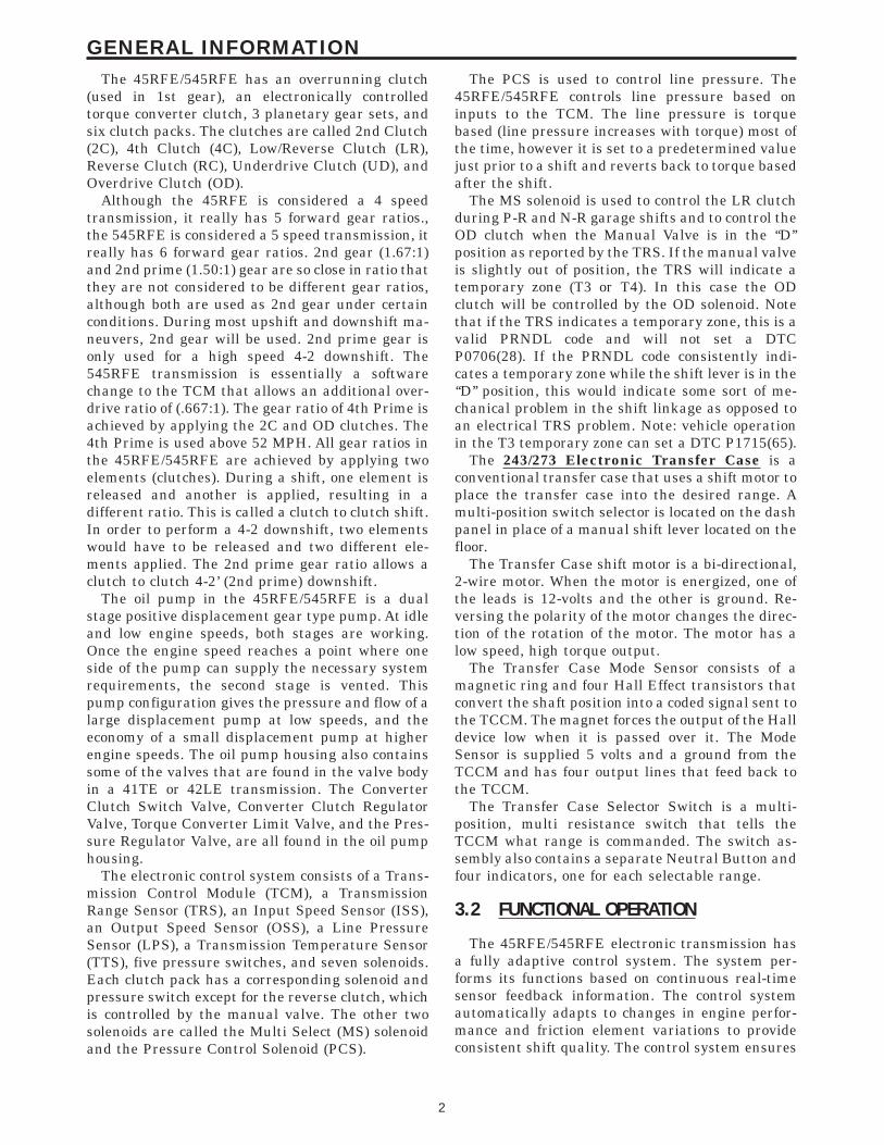
The 2003 DR will have different controller con-figurations based on the engine, transmission andelectronic throttle control combinations. You willneed to identify which controller is being used onthe vehicle that requires service. The 3.7L enginewill use a JTEC Powertrain controller with a Trans-mission Control module. The 5.7L engine will use anew NGCII Powertrain controller (PCM) withEATX Transmission controller. Note: The NGCIIcontroller is not the same as the NGCI controller.The NGCI controller combines the engine andtransmission controls into a single module and isused on the 4.7L engine. The NGCII controller willincorporate the engine and electronic throttle con-trols into a single module, the transmission func-tions will be controlled by a separate TransmissionControl Module.
NGC CONTROLLERSome of the changes you will see are several new
Diagnostics Trouble Codes and supporting diagnos-tic procedures which reflect the new combined mod-ule technology. The PCM will have four color codedconnectors, C1 through C4, (C1-BLK, C2-GRAY,C3-WHITE, C4-GREEN), each PCM connector willhave 38 pins. Two new tools are used for probingand repairing the new PCM connectors. The Termi-nal Remover Miller Tool #3638, and DiagnosticPinout box Miller Tool #8815. Miller Tool #3638 isdesigned to release the terminals from the PCMharness connectors. You must use the Miller tool#3638 to release the harness connector terminals orharness connector or terminal damage will occur.Miller tool #8815 was designed for probing the PCMharness connectors. You must use Miller tool #8815for probing the PCM terminals or damage to theterminal will occur resulting in a poor terminal topin connection. There are also new Verificationtests and module replacement procedures for thenew PCM.
The procedures contained in this manual includeall of the specifications, instructions, and graphicsneeded to diagnose*45RFE/545RFE Electronic Automatic Transmis-sion (EATX) with the 3.7L/5.7L engines* 243/273 Electronic Transfer Case
The diagnostics in this manual are based on thefailure condition or symptom being present at thetime of diagnosis.
When repairs are required, refer to the appropri-ate volume of the service manual for the properremoval and repair procedure.
Diagnostic procedures change every year. Newdiagnostic systems may be added and/or carryoversystems may be enhanced. READ THIS MANUALBEFORE TRYING TO DIAGNOSE A VEHICLE
TROUBLE CODE. It is recommended that youreview the entire manual to become familiar withall new and changed diagnostic procedures.
1.1 SYSTEM COVERAGE
This diagnostic procedures manual covers all2003 Model Year DR equipped with a 45RFE/545RFE Electronic Automatic
Transmission (EATX) with the 3.7L/5.7L enginesand 243/273 Electronic Transfer Case.
1.2 SIX -STEP TROUBLESHOOTINGPROCEDURE
Diagnosis of the 45RFE/545RFE electronic trans-mission and 243/273 Electronic Transfer Case isdone in six basic steps:
Verification of complaintVerification of any related symptomsSymptom analysisProblem isolationRepair of isolated problemVerification of proper operation
2.0 IDENTIFICATION OFSYSTEM
The 45RFE/545RFE Transmission family can beidentified by confirming the presence of a 23 pinelectrical connector on the left-hand side of thetransmission oriented vertically near the manuallever. The 243/273 Electronic Transfer Case canbe identified by the Transfer Case IdentificationTag, confirming the presence of a Shift Motor or theSelector Switch on the dash panel.
3.0 SYSTEM DESCRIPTION ANDFUNCTIONAL OPERATION
3.1 GENERAL DESCRIPTION
The 45RFE/545RFE electronic transmission is aconventional transmission in that it uses hydrauli-cally applied clutches to shift a planetary geartrain. However, the electronic control system re-places many of the mechanical and hydraulic com-ponents used in conventional transmission valvebodies.
The 45RFE/545RFE electronic transmission is afully electronically controlled transmission. TheTransmission Control Module (TCM) is similar to(but not the same as) the one used in the 41TE and42LE transmissions, therefore many similaritiesexist in function and diagnosis.
1
GENERAL INFORMATION
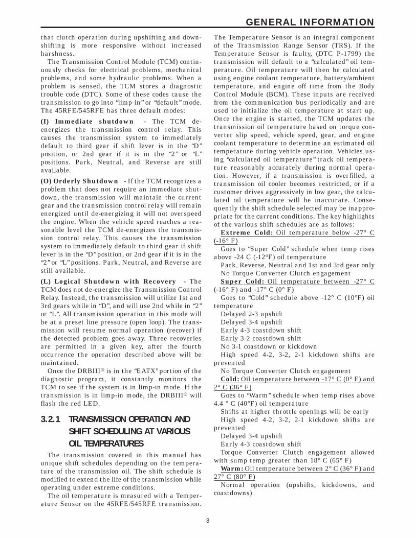
The 45RFE/545RFE has an overrunning clutch(used in 1st gear), an electronically controlledtorque converter clutch, 3 planetary gear sets, andsix clutch packs. The clutches are called 2nd Clutch(2C), 4th Clutch (4C), Low/Reverse Clutch (LR),Reverse Clutch (RC), Underdrive Clutch (UD), andOverdrive Clutch (OD).
Although the 45RFE is considered a 4 speedtransmission, it really has 5 forward gear ratios.,the 545RFE is considered a 5 speed transmission, itreally has 6 forward gear ratios. 2nd gear (1.67:1)and 2nd prime (1.50:1) gear are so close in ratio thatthey are not considered to be different gear ratios,although both are used as 2nd gear under certainconditions. During most upshift and downshift ma-neuvers, 2nd gear will be used. 2nd prime gear isonly used for a high speed 4-2 downshift. The545RFE transmission is essentially a softwarechange to the TCM that allows an additional over-drive ratio of (.667:1). The gear ratio of 4th Prime isachieved by applying the 2C and OD clutches. The4th Prime is used above 52 MPH. All gear ratios inthe 45RFE/545RFE are achieved by applying twoelements (clutches). During a shift, one element isreleased and another is applied, resulting in adifferent ratio. This is called a clutch to clutch shift.In order to perform a 4-2 downshift, two elementswould have to be released and two different ele-ments applied. The 2nd prime gear ratio allows aclutch to clutch 4-2’ (2nd prime) downshift.
The oil pump in the 45RFE/545RFE is a dualstage positive displacement gear type pump. At idleand low engine speeds, both stages are working.Once the engine speed reaches a point where oneside of the pump can supply the necessary systemrequirements, the second stage is vented. Thispump configuration gives the pressure and flow of alarge displacement pump at low speeds, and theeconomy of a small displacement pump at higherengine speeds. The oil pump housing also containssome of the valves that are found in the valve bodyin a 41TE or 42LE transmission. The ConverterClutch Switch Valve, Converter Clutch RegulatorValve, Torque Converter Limit Valve, and the Pres-sure Regulator Valve, are all found in the oil pumphousing.
The electronic control system consists of a Trans-mission Control Module (TCM), a TransmissionRange Sensor (TRS), an Input Speed Sensor (ISS),an Output Speed Sensor (OSS), a Line PressureSensor (LPS), a Transmission Temperature Sensor(TTS), five pressure switches, and seven solenoids.Each clutch pack has a corresponding solenoid andpressure switch except for the reverse clutch, whichis controlled by the manual valve. The other twosolenoids are called the Multi Select (MS) solenoidand the Pressure Control Solenoid (PCS).
The PCS is used to control line pressure. The45RFE/545RFE controls line pressure based oninputs to the TCM. The line pressure is torquebased (line pressure increases with torque) most ofthe time, however it is set to a predetermined valuejust prior to a shift and reverts back to torque basedafter the shift.
The MS solenoid is used to control the LR clutchduring P-R and N-R garage shifts and to control theOD clutch when the Manual Valve is in the ‘‘D’’position as reported by the TRS. If the manual valveis slightly out of position, the TRS will indicate atemporary zone (T3 or T4). In this case the ODclutch will be controlled by the OD solenoid. Notethat if the TRS indicates a temporary zone, this is avalid PRNDL code and will not set a DTCP0706(28). If the PRNDL code consistently indi-cates a temporary zone while the shift lever is in the‘‘D’’ position, this would indicate some sort of me-chanical problem in the shift linkage as opposed toan electrical TRS problem. Note: vehicle operationin the T3 temporary zone can set a DTC P1715(65).
The 243/273 Electronic Transfer Case is aconventional transfer case that uses a shift motor toplace the transfer case into the desired range. Amulti-position switch selector is located on the dashpanel in place of a manual shift lever located on thefloor.
The Transfer Case shift motor is a bi-directional,2-wire motor. When the motor is energized, one ofthe leads is 12-volts and the other is ground. Re-versing the polarity of the motor changes the direc-tion of the rotation of the motor. The motor has alow speed, high torque output.
The Transfer Case Mode Sensor consists of amagnetic ring and four Hall Effect transistors thatconvert the shaft position into a coded signal sent tothe TCCM. The magnet forces the output of the Halldevice low when it is passed over it. The ModeSensor is supplied 5 volts and a ground from theTCCM and has four output lines that feed back tothe TCCM.
The Transfer Case Selector Switch is a multi-position, multi resistance switch that tells theTCCM what range is commanded. The switch as-sembly also contains a separate Neutral Button andfour indicators, one for each selectable range.
3.2 FUNCTIONAL OPERATION
The 45RFE/545RFE electronic transmission hasa fully adaptive control system. The system per-forms its functions based on continuous real-timesensor feedback information. The control systemautomatically adapts to changes in engine perfor-mance and friction element variations to provideconsistent shift quality. The control system ensures
2
GENERAL INFORMATION
that clutch operation during upshifting and down-shifting is more responsive without increasedharshness.
The Transmission Control Module (TCM) contin-uously checks for electrical problems, mechanicalproblems, and some hydraulic problems. When aproblem is sensed, the TCM stores a diagnostictrouble code (DTC). Some of these codes cause thetransmission to go into ‘‘limp-in’’ or ‘‘default’’ mode.The 45RFE/545RFE has three default modes:
(I) Immediate shutdown - The TCM de-energizes the transmission control relay. Thiscauses the transmission system to immediatelydefault to third gear if shift lever is in the ‘‘D’’position, or 2nd gear if it is in the ‘‘2’’ or ‘‘L’’positions. Park, Neutral, and Reverse are stillavailable.
(O) Orderly Shutdown - If the TCM recognizes aproblem that does not require an immediate shut-down, the transmission will maintain the currentgear and the transmission control relay will remainenergized until de-energizing it will not overspeedthe engine. When the vehicle speed reaches a rea-sonable level the TCM de-energizes the transmis-sion control relay. This causes the transmissionsystem to immediately default to third gear if shiftlever is in the ‘‘D’’ position, or 2nd gear if it is in the‘‘2’’ or ‘‘L’’ positions. Park, Neutral, and Reverse arestill available.
(L) Logical Shutdown with Recovery - TheTCM does not de-energize the Transmission ControlRelay. Instead, the transmission will utilize 1st and3rd gears while in ‘‘D’’, and will use 2nd while in ‘‘2’’or ‘‘L’’. All transmission operation in this mode willbe at a preset line pressure (open loop). The trans-mission will resume normal operation (recover) ifthe detected problem goes away. Three recoveriesare permitted in a given key, after the fourthoccurrence the operation described above will bemaintained.
Once the DRBIIIt is in the ‘‘EATX’’ portion of thediagnostic program, it constantly monitors theTCM to see if the system is in limp-in mode. If thetransmission is in limp-in mode, the DRBIIIt willflash the red LED.
3.2.1 TRANSMISSION OPERATION ANDSHIFT SCHEDULING AT VARIOUSOIL TEMPERATURES
The transmission covered in this manual hasunique shift schedules depending on the tempera-ture of the transmission oil. The shift schedule ismodified to extend the life of the transmission whileoperating under extreme conditions.
The oil temperature is measured with a Temper-ature Sensor on the 45RFE/545RFE transmission.
The Temperature Sensor is an integral componentof the Transmission Range Sensor (TRS). If theTemperature Sensor is faulty, (DTC P-1799) thetransmission will default to a ‘‘calculated’’ oil tem-perature. Oil temperature will then be calculatedusing engine coolant temperature, battery/ambienttemperature, and engine off time from the BodyControl Module (BCM). These inputs are receivedfrom the communication bus periodically and areused to initialize the oil temperature at start up.Once the engine is started, the TCM updates thetransmission oil temperature based on torque con-verter slip speed, vehicle speed, gear, and enginecoolant temperature to determine an estimated oiltemperature during vehicle operation. Vehicles us-ing ‘‘calculated oil temperature’’ track oil tempera-ture reasonably accurately during normal opera-tion. However, if a transmission is overfilled, atransmission oil cooler becomes restricted, or if acustomer drives aggressively in low gear, the calcu-lated oil temperature will be inaccurate. Conse-quently the shift schedule selected may be inappro-priate for the current conditions. The key highlightsof the various shift schedules are as follows:
Extreme Cold: Oil temperature below -27° C(-16° F)
Goes to ‘‘Super Cold’’ schedule when temp risesabove -24 C (-12°F) oil temperature
Park, Reverse, Neutral and 1st and 3rd gear onlyNo Torque Converter Clutch engagementSuper Cold: Oil temperature between -27° C
(-16° F) and -17° C (0° F)Goes to ‘‘Cold’’ schedule above -12° C (10°F) oil
temperatureDelayed 2-3 upshiftDelayed 3-4 upshiftEarly 4-3 coastdown shiftEarly 3-2 coastdown shiftNo 3-1 coastdown or kickdownHigh speed 4-2, 3-2, 2-1 kickdown shifts are
preventedNo Torque Converter Clutch engagementCold: Oil temperature between -17° C (0° F) and
2° C (36° F)Goes to ‘‘Warm’’ schedule when temp rises above
4.4 ° C (40°F) oil temperatureShifts at higher throttle openings will be earlyHigh speed 4-2, 3-2, 2-1 kickdown shifts are
preventedDelayed 3-4 upshiftEarly 4-3 coastdown shiftTorque Converter Clutch engagement allowed
with sump temp greater than 18° C (65° F)Warm: Oil temperature between 2° C (36° F) and
27° C (80° F)Normal operation (upshifts, kickdowns, and
coastdowns)
3
GENERAL INFORMATION
No Torque Converter Clutch engagement alloweduntil sump temp above 18° C (65° F)
Hot (Normal operation): Oil temperature be-tween 27° C (80° F) and 115° C (240° F)
Goes to ‘‘Overheat’’ schedule above 115° C (240°F)oil temperature
Reverts to ‘‘Hot’’ when temp falls below 110° C(230 ° F)
Normal operation (upshifts, kickdowns, andcoastdowns)
Normal Torque Converter Clutch engagementoperation
Overheat: Oil temperature above 115° C (240° F)or engine coolant temperature above 118° C (244° F)
Reverts to ‘‘Hot’’ when temp falls below 110° C(230°F) oil temp
Delayed 2-3 upshift 40-51 km/h (25-32 MPH)Delayed 3-4 upshift 66-77 km/h (41-48 MPH)3rd gear FEMCC from 48-77 km/h (30-48 MPH)3rd gear PEMCC from 43-50 km/h (27-31 MPH)A DTC P0218 High Temperature Operation Acti-
vated will be set in the TCM.Causes for operation in the wrong tempera-
ture shift schedule:Extreme Cold or Cold shift schedule at start up:
Temperature Sensor or circuitry.Overheat shift schedule after extended operation:
Operation in city traffic or stop and go trafficEngine idle speed too high - Stuck AIS motorAggressive driving in low gearLong idle time in drive positionTrailer towing in OD gear position (use ‘‘3’’ posi-
tion if frequent shifting occurs)Cooling system failure causing engine to operate
over 110° C (230°F)Engine coolant temperature stays low too long - If
engine coolant temperature drops below 66° C(150°F), the transmission will disengage EMCC.Extended operation with the EMCC disengagedwill cause the transmission to overheat.
Brake switch or circuitry - The TCM disengagesthe TCC when it receives a signal from the PCMthat the brake has been depressed. A problem withthe brake switch or circuitry will cause the EMCCto disengage. Extended operation with the EMCCdisengaged will cause the transmission to overheat.
Transmission fluid overfilledTransmission cooler or cooler lines restrictedEngine cooling fan inoperativeTemperature Sensor or circuitry.
3.2.2 LINE PRESSURE CONTROLProper control of the transmission line pressure
is essential for proper operation. The 45RFE/545RFE normally uses closed loop line pressurecontrol, where actual line pressure (reported by theline pressure sensor) is continuously monitored.The TCM determines the desired (target) line pres-
sure, which is required, and adjusts the PressureControl Solenoid (PCS) until the actual line pres-sure matches the desired line pressure value. In theevent of a line pressure sensor failure DTCP0867(CB), the TCM changes to an open loop con-trol at an essentially constant line pressure.
Proper diagnosis of line pressure systems is facil-itated by the use of a special tool (T-fitting - Miller#8259) which allows the use of a mechanical pres-sure gauge to compare the line pressure sensorreading on the DRBIIIt to the gauge pressure.Technicians should compare the mechanical gaugereading with the ‘‘actual’’ and ‘‘desired’’ line pres-sure reading on the DRBIIIt. All three readingsshould closely match in pressure. Because the me-chanical and actual line pressure may not matchthe desired at low engine speeds (due to low pumpoutput RPM), line pressure should always bechecked at 1500 - 2000 RPM.
Typical Line Pressure problems include:c Mechanical and ‘‘actual’’ readings both less than
desired- If the mechanical and ‘‘actual’’ readings do notincrease significantly as engine speed is raisedabove 2000 RPM, the pressure control solenoid isusually at fault. The pressure control solenoid isusually accompanied by DTC’s P0867(C8) andP0868(C9). The PCS is located in the Transmis-sion Solenoid/TRS assembly.- If the mechanical and ‘‘actual’’ readings varywith engine speed (above 2000 RPM), the fault isoften a sticking main regulator valve. This valveis located in the transmission pump assembly.
c ‘‘Actual’’ reading on the DRBIIIt differs from theMechanical Pressure reading (higher or lower)by more than 69kPa (10 PSI). This is sometimesaccompanied by a DTC P0869(CB). The fault isusually in the Line Pressure Sensor or the LinePressure Sensor Wiring.
c All three readings match, but the ‘‘actual’’ read-ing exhibits momentary intermittent pressureincreases to 1724 kPa (250 PSI). The line Pres-sure Sensor is usually the problem. This willcause erratic shift quality (particularly a harsh3-1 coast down shift), repair by replacing theLine Pressure Sensor.
3.2.3 DRIVE LEARN PROCEDUREProcedure To Learn A Smooth 1st Neutral ToDrive Shift:
Perform this procedure only if the complaint is fora delayed or harsh shift the first time the transmis-sion is put into gear after the vehicle is allowed toset with the engine not running for at least 10minutes. Use the following steps to have the TCMlearn the 1st N-D UD CVI.
4
GENERAL INFORMATION
NOTE: The transmission oil temperaturemust be between 80 - 110°F (27 - 43°C).1. Start the engine only when the engine and
ignition have been off for at least ten (10) min-utes.
2. With the vehicle at a stop and the service brakeapplied, record the 1st N-D UD CVI while per-forming a Neutral to Drive shift. The 1st N-DUD CVI accounts for air entrapment in the UDclutch that may occur after the engine has beenoff for a period of time.
3. Repeat steps 1 and 2 until the recorded 1st N-DUD CVI value stabilizes.
NOTE: It is important that this procedure beperformed when the transmission tempera-ture is between 80 - 110°F (27 - 43°C). If thisprocedure takes too long to complete fullyfor the allowed transmission oil temperature,the vehicle may be returned to the customerwith an explanation that the shift will improvedaily during normal vehicle usage. The TCMalso learns at higher oil temperatures, butthese values (line pressure correctionvalues) are not available for viewing on theDRB III.Procedure To Learn A Smooth Neutral ToDrive Garage Shift:
Perform this procedure if the complaint is for adelayed or harsh shift when the transmission is putinto gear after the vehicle has had its first shift. Usethe following steps to have the TCM learn the NormN-D UD CVI.
NOTE: The transmission oil temperaturemust be between 80 - 110°F (27 - 43°C) tolearn the UD CVI. Additional learning occursat temperatures as low as 0°F and as high as200°F. This procedure may be performed atany temperature that experiences poor shiftquality. although the UD CVI may not change,shift quality should improve.1. Start the vehicle engine and shift to drive.2. Move the vehicle forward to a speed of at least 16
km/h (10 MPH) and come to a stop. This ensuresno air is present in the UD hydraulic circuit.
3. Perform repeated N-D shifts at a stop whilepausing in Neutral for at least 2-3 seconds andmonitor Norm N-D UD CVI volume until thevalue stabilizes. The value will change duringthe N-D shift. This is normal since the UD valueis different for the N-D shift then the normalvalue shown which is used for 4-3 coastdown andkickdowns. Perform repeated shifts in this tem-
perature range until the Norm N-D UD CVIvalue stabilizes and the N-1 shifts becomesmooth.
4. This procedure may be performed at any temper-ature that experiences poor N-D shift quality.Although the Norm N-D UD CVI may notchange, shift quality should improve.
Procedure To Learn The 1st 2-3 Shift After ARestart Or Shift To Reverse:
Use the following steps to have the TCM learn the1st 2-3 shift OD CVI.
NOTE: The transmission oil temperaturemust be above 80°F (27°C).1. With the vehicle engine running, select reverse
gear for over 2 seconds.2. Shift the transmission to Drive and accelerate
the vehicle from a stop at a steady 15 degreethrottle opening and perform a 2-3 shift whilenoting the OD CVI. During the shift, a differentvalue may appear on the screen, which is the 1st2-3 OD CVI.
3. Repeat steps 1 and 2 until the 1st 2-3 upshiftbecomes smooth and the 1st 2-3 OD CVI stabi-lizes.
Procedure To Learn A Smooth 2-3 And 3-4Upshift:
Use the following steps to have the TCM learn theOD and 4C CVI’s.
NOTE: The transmission oil temperaturemust be above 110°F (43°C).1. Accelerate the vehicle from a stop at a steady 15
degree throttle opening and perform multiple1-2, 2-3, and 3-4 upshifts. The 2nd 2-3 shiftfollowing a restart or shift to reverse will beshown during the shift as a value between the1st 2-3 OD CVI and the normal OD CVI. Up-dates to the normal OD CVI will occur after the2nd shift into 3rd gear, following a restart orshift to reverse.
2. Repeat step 1 until the 2-3 and 3-4 shifts becomesmooth and the OD and 4C CVI become stable.
Procedure To Learn A Smooth 4-3 CoastdownAnd Part Throttle 4-3 Kickdown:
Use the following steps to have the TCM learn theUD shift volume.
NOTE: The transmission oil temperaturemust be above 110°F (43°C).1. At a vehicle speed between 64-97 km/h (40-60
MPH), perform repeated 4-3 kickdown shifts.2. Repeat step 1 until the UD volume becomes
somewhat stable and the shift becomes smooth.
5
GENERAL INFORMATION
Procedure To Learn A Smooth 1-2 Upshift and3-2 Kickdown:
Use the following steps to have the TCM learn the2C shift volume.
NOTE: The transmission oil temperaturemust be above 110°F (43°C).1. With a vehicle speed below 48 km/h (30 MPH)
and the transmission in 3rd gear, perform mul-tiple 3-2 kickdowns.
2. Repeat step 1 until the 3-2 kickdowns becomesmooth and the 2C CVI becomes stable.
Procedure To Learn A Smooth Manual 2-1Pulldown Shift As Well As A Neutral To Re-verse Shift:
Use the following steps to have the TCM learn theLR volume.
NOTE: The transmission oil temperaturemust be above 110°F (43°C).1. With the vehicle speed around 40-48 km/h (25-30
MPH) in Manual 2nd, perform manual pull-downs to Low or 1st gear at closed throttle.
2. Repeat step 1 until the LR CVI becomes stableand the manual 2-1 becomes smooth.
Procedure To Learn A Smooth Neutral To Re-verse Shift:
Perform the following shifts.
NOTE: The transmission oil temperaturemust be above 110°F (43°C).1. With the vehicle at a stop, perform Neutral to
Reverse shifts until the shift is smooth. Anunlearned Neutral to Reverse shift may be harshor exhibit a double bump.
If any of the shifts are still not smooth after theclutch volume stabilizes, an internal transmissionproblem may be present.
Procedure To Learn A Smooth 4-5 Upshift for545RFE:
Use the following steps to have the TCM learn theALT 2C CVI.
NOTE: The transmission oil temperaturemust be above 110°F (43°C).1. Accelerate the vehicle through 88 km/h (55mph)
at a steady 10-15 degree throttle opening andperform multiple 4-5 upshifts.
2. Repeat step 1 until the 4-5 shift becomes smoothand the ALT 2C CVI become stable. Note: Thereis a separate ALT 2C CVI volume used andlearned for 4-5 shifts. It is independent of the 2CCVI learned on 3-2 kickdowns.
3.3 DIAGNOSTIC TROUBLE CODES
Diagnostic trouble codes (DTC’s) are codes storedby the Transmission Control Module (TCM) thathelp us diagnose Transmission problems. They areviewed using the DRBIIIt scan tool.
Always begin by performing a visual inspection ofthe wiring, connectors, cooler lines and the trans-mission. Any obvious wiring problems or leaksshould be repaired prior to performing any diagnos-tic test procedures. Some engine driveability prob-lems can be misinterpreted as a transmission prob-lem. Ensure that the engine is running properlyand that no PCM DTC’s are present that couldcause a transmission complaint.
If there is a communication bus problem, troublecodes will not be accessible until the problem isfixed. The DRBIIIt will display an appropriatemessage. The following is a possible list of causesfor a bus problem:
– open or short to ground/battery in PCI buscircuit.
– internal failure of any module or component onthe bus
Each diagnostic trouble code is diagnosed byfollowing a specific testing sequence. The diagnostictest procedures contain step-by-step instructionsfor determining the cause of a transmission diag-nostic trouble code. Possible sources of the code arechecked and eliminated one by one. It is not neces-sary to perform all of the tests in this book todiagnose an individual code. These tests are basedon the problem being present at the time that thetest is run.
If the TCM records a DTC that will adverselyaffect vehicle emissions, it will request (via thecommunication bus) that the PCM illuminate theMalfunction Indicator Lamp (MIL). Although theseDTC’s will be stored in the TCM immediately as a 1trip failure, it may take up to five minutes ofaccumulated trouble confirmation to set the DTCand illuminate the MIL. Three consecutive success-ful OBDII/EURO III trips or clearing the DTC’swith a diagnostic tool (DRBIIIt or equivalent) isrequired to extinguish the MIL. When the TCMrequests that the PCM illuminate the MIL, thePCM sets a DTC ($89) to alert the technician thatthere are DTC’s in the TCM. This must also beerased in the PCM in order to extinguish the MIL.
3.3.1 HARD CODEAny Diagnostic Trouble Code (DTC) that is set
whenever the system or component is monitored isa HARD code. This means that the problem is thereevery time the TCM checks that system or compo-nent. Some codes will set immediately at start upand others will require a road test under specific
6
GENERAL INFORMATION
conditions. It must be determined if a code isrepeatable (Hard) or intermittent before attempt-ing diagnosis.
3.3.2 ONE TRIP FAILURESA One Trip Failure, when read from the TCM, is
a hard OBDII/EURO III code that has not maturedto the full 5 minutes. This DTC can take up to fiveminutes of problem identification before illuminat-ing the MIL
3.3.3 INTERMITTENT CODEA diagnostic trouble code that is not there every
time the TCM checks the circuit or function is an‘‘intermittent’’ code. Some intermittent codes, suchas codes are caused by wiring or connector prob-lems. However intermittent Speed ratio codes areusually caused by intermittent hydraulic seal leak-age in the clutch and/or accumulator circuits. Inter-mittent speed ratio codes can be set by intermittentspeed sensor circuitry or by line noise being inducedonto one or both of the speed sensor signal circuits.Problems that come and go like this are the mostdifficult to diagnose, they must be looked for underthe specific conditions that cause them.
3.3.4 STARTS SINCE SET COUNTERThe Starts Since Set counter counts the number
of times the vehicle has started since the mostrecent DTC was set. The counter will count up to255 starts. Note that this counter only applies to thelast code set.
When there are no diagnostic trouble codes storedin memory, the DRBIIIt will display ‘‘NO DTC’sPRESENT’’ and the reset counter will show‘‘STARTS SINCE CLEAR’’ = XXX.
The number of starts helps determine if thediagnostic trouble code is hard or intermittent.
– If the number of starts is less than 3, the codeis usually a hard code.
– If the number of starts is greater than 3, it isconsidered an intermittent code. This meansthat the engine has been started most of thetime without the code recurring.
3.3.5 TROUBLE CODE ERASUREA Diagnostic trouble code will be cleared from
TCM memory if it has not reset for 40 warm-upcycles.
A warm-up cycle is defined as ‘‘sufficient vehicleoperation such that the coolant temperature hasrisen by at least 22° C (40° F) from engine startingand reaches a minimum temperature of 71° C(160° F).
The Malfunction Indicator Lamp (MIL) will turnoff after 3 good trips or when the DTC’s are clearedfrom the TCM.
3.3.6 EATX DTC EVENT DATAEATX DTC EVENT DATA can be used as a
diagnostic aid when experiencing Electronic Trans-missions with intermittent problems. When a Diag-nostic Trouble Code (DTC) is set, the vehicles trans-mission inputs are stored in the controller memoryand are retrievable with the DRBIIIt. This infor-mation can be helpful when a DTC can not beduplicated.
The EATX DTC EVENT DATA is located in theDRBIIIt, under the Transmission system menu, inthe sub-screen Miscellaneous. It is a good practiceto document the EATX DTC EVENT DATA beforebeginning any diagnostic or service procedure.
A thorough understanding of how the transmis-sion works is beneficial in order to interpret thedata correctly. These skills are necessary in order toavoid an incorrect diagnosis.
A MASTERTECH video and reference book wasproduced in January 2002 that explains many ofthe features of the EATX DTC EVENT DATA withseveral examples on how to interpret the informa-tion and suggested training material to help under-stand all the specifics.EATX DTC EVENT DATA can only be erased by:1. Disconnecting the battery.2. Performing a DRBIIIt QUICK LEARN proce-
dure.3. Reprogramming the NGC/EATX controller.Erasing Transmission DTCs does not clear theEATX DTC EVENT DATA.
7
GENERAL INFORMATION
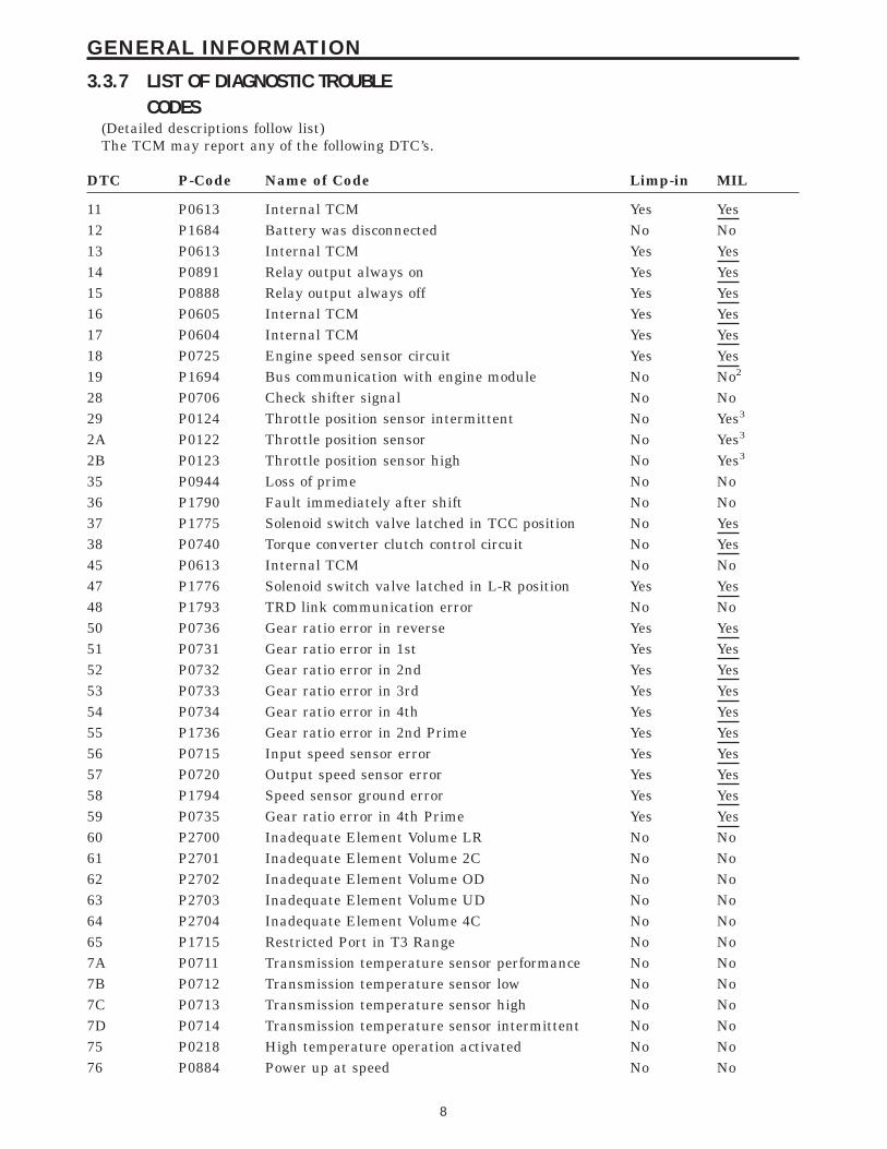
3.3.7 LIST OF DIAGNOSTIC TROUBLECODES
(Detailed descriptions follow list)The TCM may report any of the following DTC’s.
DTC P-Code Name of Code Limp-in MIL
11 P0613 Internal TCM Yes Yes12 P1684 Battery was disconnected No No13 P0613 Internal TCM Yes Yes14 P0891 Relay output always on Yes Yes15 P0888 Relay output always off Yes Yes16 P0605 Internal TCM Yes Yes17 P0604 Internal TCM Yes Yes18 P0725 Engine speed sensor circuit Yes Yes19 P1694 Bus communication with engine module No No2
28 P0706 Check shifter signal No No29 P0124 Throttle position sensor intermittent No Yes3
2A P0122 Throttle position sensor No Yes3
2B P0123 Throttle position sensor high No Yes3
35 P0944 Loss of prime No No36 P1790 Fault immediately after shift No No37 P1775 Solenoid switch valve latched in TCC position No Yes38 P0740 Torque converter clutch control circuit No Yes45 P0613 Internal TCM No No47 P1776 Solenoid switch valve latched in L-R position Yes Yes48 P1793 TRD link communication error No No50 P0736 Gear ratio error in reverse Yes Yes51 P0731 Gear ratio error in 1st Yes Yes52 P0732 Gear ratio error in 2nd Yes Yes53 P0733 Gear ratio error in 3rd Yes Yes54 P0734 Gear ratio error in 4th Yes Yes55 P1736 Gear ratio error in 2nd Prime Yes Yes56 P0715 Input speed sensor error Yes Yes57 P0720 Output speed sensor error Yes Yes58 P1794 Speed sensor ground error Yes Yes59 P0735 Gear ratio error in 4th Prime Yes Yes60 P2700 Inadequate Element Volume LR No No61 P2701 Inadequate Element Volume 2C No No62 P2702 Inadequate Element Volume OD No No63 P2703 Inadequate Element Volume UD No No64 P2704 Inadequate Element Volume 4C No No65 P1715 Restricted Port in T3 Range No No7A P0711 Transmission temperature sensor performance No No7B P0712 Transmission temperature sensor low No No7C P0713 Transmission temperature sensor high No No7D P0714 Transmission temperature sensor intermittent No No75 P0218 High temperature operation activated No No76 P0884 Power up at speed No No
8
GENERAL INFORMATION
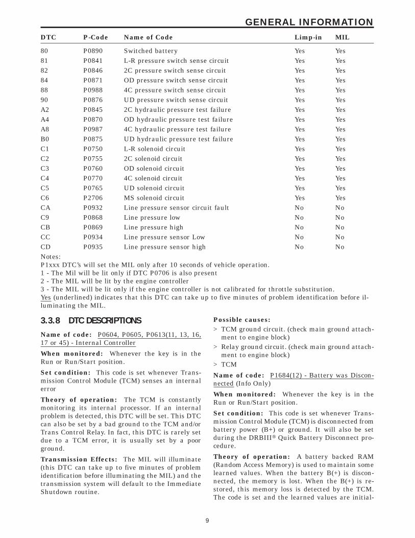
DTC P-Code Name of Code Limp-in MIL
80 P0890 Switched battery Yes Yes81 P0841 L-R pressure switch sense circuit Yes Yes82 P0846 2C pressure switch sense circuit Yes Yes84 P0871 OD pressure switch sense circuit Yes Yes88 P0988 4C pressure switch sense circuit Yes Yes90 P0876 UD pressure switch sense circuit Yes YesA2 P0845 2C hydraulic pressure test failure Yes YesA4 P0870 OD hydraulic pressure test failure Yes YesA8 P0987 4C hydraulic pressure test failure Yes YesB0 P0875 UD hydraulic pressure test failure Yes YesC1 P0750 L-R solenoid circuit Yes YesC2 P0755 2C solenoid circuit Yes YesC3 P0760 OD solenoid circuit Yes YesC4 P0770 4C solenoid circuit Yes YesC5 P0765 UD solenoid circuit Yes YesC6 P2706 MS solenoid circuit Yes YesCA P0932 Line pressure sensor circuit fault No NoC9 P0868 Line pressure low No NoCB P0869 Line pressure high No NoCC P0934 Line pressure sensor Low No NoCD P0935 Line pressure sensor high No NoNotes:P1xxx DTC’s will set the MIL only after 10 seconds of vehicle operation.1 - The Mil will be lit only if DTC P0706 is also present2 - The MIL will be lit by the engine controller3 - The MIL will be lit only if the engine controller is not calibrated for throttle substitution.Yes (underlined) indicates that this DTC can take up to five minutes of problem identification before il-luminating the MIL.
3.3.8 DTC DESCRIPTIONSName of code: P0604, P0605, P0613(11, 13, 16,17 or 45) - Internal Controller
When monitored: Whenever the key is in theRun or Run/Start position.
Set condition: This code is set whenever Trans-mission Control Module (TCM) senses an internalerror
Theory of operation: The TCM is constantlymonitoring its internal processor. If an internalproblem is detected, this DTC will be set. This DTCcan also be set by a bad ground to the TCM and/orTrans Control Relay. In fact, this DTC is rarely setdue to a TCM error, it is usually set by a poorground.
Transmission Effects: The MIL will illuminate(this DTC can take up to five minutes of problemidentification before illuminating the MIL) and thetransmission system will default to the ImmediateShutdown routine.
Possible causes:> TCM ground circuit. (check main ground attach-
ment to engine block)> Relay ground circuit. (check main ground attach-
ment to engine block)> TCM
Name of code: P1684(12) - Battery was Discon-nected (Info Only)
When monitored: Whenever the key is in theRun or Run/Start position.
Set condition: This code is set whenever Trans-mission Control Module (TCM) is disconnected frombattery power (B+) or ground. It will also be setduring the DRBIIIt Quick Battery Disconnect pro-cedure.
Theory of operation: A battery backed RAM(Random Access Memory) is used to maintain somelearned values. When the battery B(+) is discon-nected, the memory is lost. When the B(+) is re-stored, this memory loss is detected by the TCM.The code is set and the learned values are initial-
9
GENERAL INFORMATION
ized to known constants or previously learned val-ues from EEPROM (Electronic Erasable Program-mable Read Only Memory). This results in thereinitialization of some parameters.
Transmission Effects: Loss of trouble code data.The Transmission system will default to the Imme-diate shutdown routine if power is lost while oper-ating the vehicle. Normal operation is resumed ifthe power is restored during the same key start.
Possible causes:> Battery voltage removed from TCM (Fused B+)> TCM disconnected> Dead Battery> Low battery voltage during cranking> Quick Battery Disconnect by DRBIIIt or MDS> Bad TCM ground circuit.
Name of code: P0891(14) - Relay Always On
When monitored: When ignition key is turnedfrom ‘‘off ’’ position to ‘‘run’’ position and/or ignitionkey is turned from ‘‘crank’’ position to ‘‘run’’ posi-tion.
Set condition: This code is set if the Transmis-sion Control Module (TCM) senses greater than 3volts at the Trans Control Relay Output terminal(s)of the TCM prior to the TCM energizing the relay.
Theory of operation: The transmission controlrelay is used to supply power to the solenoids andpressure switches when the transmission is in nor-mal operating mode. The relay output is fed back tothe TCM through pins 16, 17, and 36. It is referredto as ‘‘Transmission Control Relay Output’’. Thiscircuit does not supply power to the TCM, it is onlya sense circuit. When the relay is off, no power issupplied to the solenoids and pressure switches,and the transmission is in ‘‘limp-in’’ or ‘‘default’’mode.
Transmission Effects: The MIL will illuminate(this DTC can take up to five minutes of problemidentification before illuminating the MIL) and thetransmission system will default to the ImmediateShutdown routine.
Possible causes:> Short to voltage in the Transmission Solenoid/
TRS Assembly (internal into any solenoid controlcircuit)
> Short to voltage on any solenoid control circuit> Relay contacts stuck together.> Short to voltage in Transmission Control Relay
output circuit(s).> Short to voltage in Transmission Relay Control
circuit.> Short to voltage on any pressure switch sense
circuit.
> TCM connector problems.> TCM.
Name of code: P0888(15) - Relay Output AlwaysOff
When monitored: Continuously
Set condition: This code is set when less than 3volts are present at any transmission control relayoutput (pins 16,17 or 36) circuits at the Transmis-sion Control Module (TCM) when the TCM is ener-gizing the relay.
Theory of operation: The Transmission ControlRelay is used to supply power to the solenoids andpressure switches when the transmission is in nor-mal operating mode. The relay output is fed back tothe TCM through pins 16, 17, and 36. It is referredto as ‘‘Transmission Control Relay Output’’. Thiscircuit does not supply power to the TCM, it is onlya sense circuit. When the relay is off, no power issupplied to the solenoids and pressure switches,and the transmission is in ‘‘limp-in’’ or ‘‘default’’mode.
After a controller reset (ignition key turned to the‘‘run’’ position or after cranking engine), the control-ler energizes the relay. Prior to this the TCMverifies that the contacts are open by checking forno voltage at the switched battery terminals. Afterthe relay is energized, the TCM monitors the ter-minals to verify that the voltage is greater than 3volts.
Transmission Effects: The MIL will illuminate(this DTC can take up to five minutes of problemidentification before illuminating the MIL) and thetransmission system will default to the ImmediateShutdown routine.
Possible causes:> Transmission Control Relay (intermittent relay
function caused by oxidized or contaminated re-lay contacts)
> Short to ground or open circuit in the transmis-sion control relay output circuit(s)
> Short to ground or open circuit in the Transmis-sion Solenoid/TRS assembly
> TCM connector problem> Relay connector problem> Relay Ground circuit> TCM Ground circuit(s)> TCM
Name of code: P0725(18) - Engine Speed SensorCircuit
NOTE: This code is not a Transmission InputSpeed Sensor DTCWhen monitored: Continuously with engine run-ning.
10
GENERAL INFORMATION
Set condition: This code is set when the enginespeed calculated by the Transmission Control Mod-ule (TCM) is less than 390 RPM, while the enginespeed broadcast by the PCM is greater than 383RPM. The DTC also sets if the calculated enginespeed is greater than 8000 RPM for more that 2.0seconds.
Theory of operation: The TCM uses the cranksensor signal to calculate engine RPM. The TCMuses RPM data from the PCM, which is broadcastover the communication bus to determine if theengine is running. The TCM continuously comparescalculated engine speed to the engine RPM reportedon the bus, by the PCM, so that loss of crankshaftposition sensor signal to the TCM will not bemisinterpreted as engine not running.
Transmission Effects: The MIL will illuminate(this DTC can take up to five minutes of problemidentification before illuminating the MIL) and thetransmission system will default to the LogicalShutdown routine.
Possible causes:> Open or short in engine speed sensor circuit.
(Crank sensor signal)> TCM connector problems (Crank sensor signal or
sensor ground terminals)> Open or short in sensor ground circuit> Low engine idle speed> TCM> PCM.
Name of code: P1694(19) - Bus Communicationwith Engine Module
When monitored: Continuously with key on.
Set condition: If no bus messages are receivedfrom the Powertrain Control Module (PCM) for 10seconds.
Theory of operation: The TCM communicateswith the PCM using the communication bus. Itrelies on certain information to function properly.The TCM continuously monitors the bus to checkfor messages broadcast from the PCM.
Transmission Effects: Delayed 3-4 shifts. NoEMCC and early 3-4 shifts for a few minutes afterengine is started. Generally poor shift quality.
Possible causes:> Open or shorted bus circuit> TCM> PCM
Name of code: P0706(28) - Check Shifter Signal
When Monitored: Continuously with the key on.
Set Condition: Any occurrences of an invalid
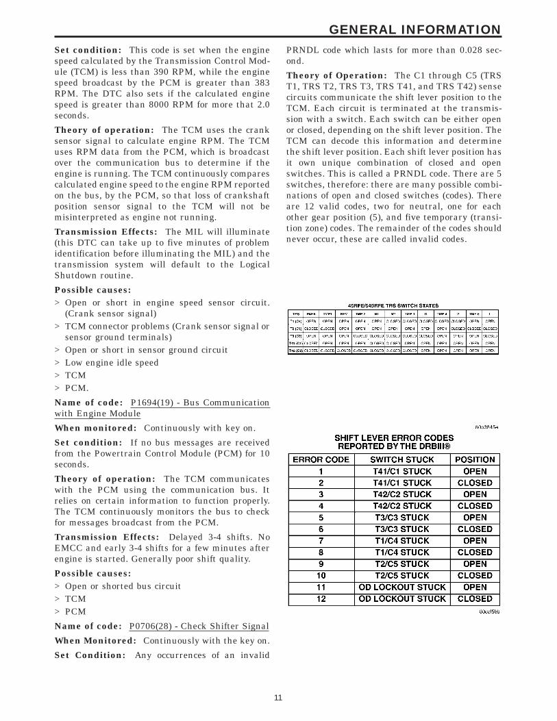
PRNDL code which lasts for more than 0.028 sec-ond.
Theory of Operation: The C1 through C5 (TRST1, TRS T2, TRS T3, TRS T41, and TRS T42) sensecircuits communicate the shift lever position to theTCM. Each circuit is terminated at the transmis-sion with a switch. Each switch can be either openor closed, depending on the shift lever position. TheTCM can decode this information and determinethe shift lever position. Each shift lever position hasit own unique combination of closed and openswitches. This is called a PRNDL code. There are 5switches, therefore: there are many possible combi-nations of open and closed switches (codes). Thereare 12 valid codes, two for neutral, one for eachother gear position (5), and five temporary (transi-tion zone) codes. The remainder of the codes shouldnever occur, these are called invalid codes.
11
GENERAL INFORMATION
NOTE: If you are using the transmissionsimulator and do not push the OD off buttonin the vehicle when performing a Shift Leverposition test, you will receive a code 11 ODlockout stuck openTransmission Effects and possible causes:(This code alone will not illuminate the MIL)> Excessive metal debris in the transmission oil
pan> Worn Code Plate. Check for heavy wearing by
TRS switch contacts> Intermittent C1 through C5 (T1, T2, T3, T41 or
T42) circuits.Check for corrosion, terminal push-outs orspread terminals at TCM connector and/or 23-way transmission connector.
> TRS connector not plugged in, or unplugged withthe key on.
> TRS C1 through C5 (T1, T2, T3, T41, or T42)circuit(s) are open, shorted to ground, or shortedto 12 volts.
> TRS> TCM
Name of code: P0124(29) - Throttle PositionSensor/APPS Intermittent
Name of code: P0122(2A) - Throttle PositionSensor /APPS Low
Name of code: P0123(2B) - Throttle PositionSensor /APPS High
When monitored: Whenever the key is on or theengine is running. Engine speed > 500 rpm
Set condition: EATXP0124 - Throttle angle change > 5° in 7millisecondsthe Fault set time milliseconds 0.448 secondsP0122 - Throttle angle < 6° the Fault Set Time:0.448 secondsP0123 - Throttle angle > 120.6° the Fault Set Time:0.448 seconds
Set condition: NGCII with Electronic ThrottleControlP0122 - is set if the pedal position sensor voltagefalls below (.4v Diesel / .5v Gas).P0123 - is set if the pedal position sensor voltagerises above (4.8v Diesel / 4.8v Gas).P0124 - is set if the change in pedal position sensorvoltage falls outside the limits
Theory of operation: EATX -The transmissioncontroller receives the throttle position signal andits ground from the Throttle Position Sensor (TPS).The TPS has a 5 volt pull up supplied by the enginecontroller. The throttle signal is checked for out-of-range as well as intermittent operation (excessivesignal changes). The engine controller transmitsthe throttle value via the bus. Most engine control-
lers can synthesize the throttle value if the throttleposition sensor signal is lost. If a throttle error isdetected by the transmission controller and thethrottle value is available via the bus, the busthrottle value will be used and normal operationwill continue, however a throttle fault code will beset. If a throttle error is detected and the throttlevalue is not available via the bus, normal operationwill be discontinued, a throttle DTC will be set, andthe MIL will be turned on after 5 min. of substitutedoperation.
Theory of operation: NGCII with ElectronicThrottle Control 5.7L engines are equipped with aNGCII control module, which controls the ThrottlePlate Position, based on torque management (re-quest). This system has a throttle cable that isattached to two Accelerator Position Sensors in-stead of the throttle body. The throttle plate will notmove with the ignition on while pressing the Accel-erator Pedal. The only way to move the throttleplate with the ignition on is by using the DRBIII.The ETC Motor Assembly contains two ThrottlePosition Sensors, two springs, and the ETC Motor,which are replaced as a complete assembly. The TPSensors inform the PCM of the position of thethrottle plate. The ETC Motor has a positive andnegative circuit. The PCM controls these circuitsusing Pulse Width Modulation. To open the throttleplate the PCM provides pulse width voltage to thepositive side of the ETC motor and grounds thenegative side. To close the throttle plate the PCMprovides pulse width voltage to the negative side ofthe ETC motor and grounds the positive side. Oneof the springs is used against opening the throttleplate and the other is used against closing thethrottle plate. The PCM uses the APP Sensor inputsalong with inputs from the other Sensors to deter-mine throttle opening. Duplicate sensors are usedto check one sensor against its counterpart. Two TPSensor, two, APP Sensors, two Brake Switch inputs,and two Speed Control inputs are used with theNGCII system. When duplicate Sensors are notused, the single Sensor is checked against a valuethat is calculated by the PCM. When a sensor fails,the PCM limits the opening of the Throttle blade.The customer may complain limited power andthrottle control after the MIL and or ETC lightilluminate. The ETC Light will constantly illumi-nate or flash depending on which component hasfailed. The ETC Motor Assembly will be referred toas Throttle Body Assembly in the Diagnostic andService information. A slight delay in cranking maybe noticed when starting the engine. When startingthe vehicle the ETC Motor is tested before theengine is allowed to crank. The test includes open-ing and closing the throttle plate to verify properoperation before starting the engine for safety rea-sons. A No Crank Condition may occur if the Igni-
12
GENERAL INFORMATION
tion in left in the on position for a period of timebefore actually cranking the engine. The PCM willtest the throttle plate as often as it wants and willnot allow cranking during this procedure. Thethrottle signal is checked for out-of-range as well asintermittent operation (excessive signal changes).The engine controller transmits the throttle valuevia the bus. Most engine controllers can synthesizethe throttle value if the throttle position sensorsignal is lost. If a throttle error is detected by thetransmission controller and the throttle value isavailable via the bus, the bus throttle value will beused and normal operation will continue, however athrottle fault code will be set. If a throttle error isdetected and the throttle value is not available viathe bus, normal operation will be discontinued, athrottle DTC will be set, and the MIL will be turnedon after 5 min. of substituted operation.
Transmission Effects:* If throttle value available via the bus -No effect.* If throttle value not available via the bus, adefault throttle value is used, Torque converterlock-up inhibited, 4th gear is inhibited, Limitedtransmission shift schedule, MIL on after 5 min. ofsubstituted operation.
Possible causes:> Wiring problem in APPS or TPS circuits> APPS> TPS> Throttle body> PCM> TCM
Name of code: P0944(35) - Loss Of Prime
When monitored: If the transmission is slippingin any forward gear and all the pressure switchesare indicating no pressure, a loss of prime test isrun.
Set condition: If the transmission begins to slipin any forward gear, and all pressure switches areopen, a loss of prime test begins. All availableelements are momentarily turned on by the Trans-mission Control Module (TCM) to see if pump primeexists. The code is set if none of the pressureswitches respond. The TCM will continue to run theloss of prime test until pump pressure returns.Note: Loss of Prime test is not run when transmis-sion temperature is ‘‘Super Cold’’.
Theory of operation: The loss of prime test isused to prevent transmission defaults, which can becaused by a lack of pump prime.
Transmission Effects: Vehicle will not move ortransmission slips. Normal operation will continueif pump prime returns.
Possible causes:> Low transmission fluid level> Transmission fluid filter improperly installed
(Seal installed onto filter neck instead of intopump bore, seal not fully seated against pumpbore housing, filter neck not engaged into pump,bolts loose or O-ring missing or damaged)
> Transmission fluid filter clogged, damaged orcracked
> Transmission has massive hydraulic leak (valvebody pipe plugs missing, etc.)
> Transmission oil pump> Transmission oil pump drive is sheared or dam-
aged> PRNDL indicates a valid OD code in the hydrau-
lic reverse position
Name of code: P1790(36) - Fault ImmediatelyAfter Shift
When monitored: When a speed ratio error DTC(50 through 55) is stored.
Set condition: This code is set if the associatedspeed ratio code is stored within 1.3 seconds after ashift.
Theory of operation: This code will only bestored along with a 50 series code. If this code is set,it indicates a probable hydraulic (line pressure) ormechanical problem exists. When this code is set,diagnosing the transmission should be based on theassociated speed ratio code and mechanical causesshould be considered first.
Transmission Effects: None
Possible causes:> Mechanical causes as listed under associated
speed ratio code.> Inadequate line pressure> Cut or damaged clutch piston seals
Name of code: P1775(37) - Solenoid Switch ValveLatched in TCC Position
When monitored: During an attempted shift into1st gear.
Set condition: This code is set if 6 unsuccessfulattempts are made to get into 1st gear, with trans-mission temp above 27° C (80° F), in one given keystart.
Theory of operation: The solenoid switch valve(SSV) controls the direction of the transmissionfluid when the L-R solenoid is energized. The SSVwill be in the downshifted position in 1st gear, thusdirecting the fluid to the L-R clutch circuit. In 2nd,3rd, and 4th, it will be in the upshifted position anddirects the fluid into the torque converter clutch(TCC).
13
GENERAL INFORMATION
When shifting into 1st gear, a special hydraulicsequence is performed to ensure SSV movementinto the downshifted position. The L-R pressureswitch is monitored to confirm SSV movement. Ifmovement is not confirmed (the L-R pressureswitch does not close), EMCC is inhibited until SSVoperation is confirmed.
Transmission Effects: Transmission will have1st gear and no EMCC operation. The MIL willilluminate after 5 minutes of no EMCC operation.
Possible causes:> Valve body - Solenoid Switch Valve stuck in TCC
position> L-R solenoid armature or plunger broken -
should also set DTC P0841 (81) and often setsP0740 (38)
> Solenoid malfunction - may also set codeP0841(81)
> L-R Pressure Switch Sense circuit shorted tobattery
> High idle speed> PRNDL indicates a valid OD code in the hydrau-
lic reverse position
Name of code: P0740(38) - Torque ConverterClutch Control Circuit
When monitored: During Electronically Modu-lated Converter Clutch (EMCC) Operation
Set condition: The code will be set if one of thefollowing events happens three times in a given keystart, at a throttle angle less than 30(a) With the transmission in EMCC, the TCC/L-R
solenoid achieves the maximum duty cycle andis still unable to pull the engine speed within 60RPM of input speed.
b) With the transmission in FEMCC, the TCCRPM (Engine speed - Input speed) is more than100 RPM for 7.2 seconds.
Theory of operation: When in 2nd, 2nd Prime,3rd, or 4th gear, the torque converter clutch (TCC)can be engaged when certain conditions are met.The TCC piston is electronically modulated by in-creasing the duty cycle of the L-R solenoid until thetorque converter slip difference (difference betweenengine and transmission input speed) is within 60RPM. Then the L-R solenoid is fully energized(FEMCC / 100% duty cycle). Torque converter slip ismonitored in FEMCC to ensure adequate clutchcapacity.
Transmission Effects: EMCC will still be avail-able after code is set. MIL will illuminate after 5minutes of accumulated slip in FEMCC. The trans-mission will attempt normal operation (no limp-in)even after the MIL is illuminated.
Possible causes:> Cut converter hub O-ring and/or failed torque
converter - both should be replaced during arebuild with code P0740(38) present.
> Sticky CC Regulator valve
Name of code: P1776(47) - Solenoid Switch Valve(SSV) Latched in L-R Position
When monitored: Continuously when doing par-tial or full EMCC (PEMCC or FEMCC)
Set condition: If the transmission senses the L-Rpressure switch closing while performing PEMCCor FEMCC. This code will be set after four unsuc-cessful attempts to perform PEMCC or FEMCC.
Theory of operation: The solenoid switch valve(SSV) controls the direction of the transmissionfluid when the L-R solenoid is energized. SSV willbe in the downshifted position in 1st gear, thusdirecting the fluid to the L-R clutch circuits. In 2nd,3rd, and 4th, the SSV will be in the upshiftedposition and directs the fluid into the torque con-verter clutch (TCC). When doing PEMCC orFEMCC, the L-R pressure switch should indicate nopressure if the SSV is in the TCC position. If theL-R pressure switch indicates pressure while inPEMCC or FEMCC, EMCC operation is abortedand inhibited to avoid inadvertent application ofthe L-R clutch. Partial EMCC will be attempted ifthe L-R pressure switch does not indicate pressure.Four occurences of detection of L-R pressure resultsin setting the code.
Transmission Effects: EMCC is inhibited andthe transmission system will default to the OrderlyShutdown routine. (this DTC can take up to fiveminutes of problem identification before illuminat-ing the MIL)
Possible causes:> Valve body - Solenoid Switch Valve stuck in L-R
position> Intermittent short to ground or open circuit in
L-R Pressure Switch Sense circuit (with codeP0841 only)
> Solenoid/TRS assembly (with code P0841(81)only)
> TCM (with code P0841(81) only)
Name of Code: P1793(48) - Torque Reduction(TRD) Link Communication Error
When Monitored: During torque managed shifts(Throttle angle above 54 degrees). This system isalso tested whenever the vehicle is stopped and theengine speed is below 1000 RPM.
Set condition: This code is set when the Trans-mission Control Module (TCM) sends two subse-quent torque reduction messages to the PowertrainControl Module (PCM) via the TRD link circuit and
14
GENERAL INFORMATION
does not receive a confirmation from the PCM overthe communication bus.
Theory of Operation: During high torque shiftsthe TCM will send a message requesting that thePCM reduce engine power until the shift is com-pleted. This message is sent from the TCM to thePCM across the Torque Management RequestSense Circuit. The PCM will acknowledge the TCMrequest by sending a confirmation message acrossthe communication bus. The TRD Link communi-cation is also tested periodically for operation when-ever the engine is running and the vehicle is notmoving with zero degrees throttle.
Transmission Effects: Maximum throttle angleused by TCM will be 54 degrees. As a result acustomer may complain about loss of performanceand/or normal and WOT shifts may be harsh.
Possible Causes:Sticky Throttle Position Sensor (TPS)> Wiring or Connector problems in the Torque
Management Request Sense Circuit> Bus communication problems.> PCM> TCM
Name of code:P0736(50) - Gear Ratio Error in ReverseP0731(51) - Gear Ratio Error in 1stP0732(52)- Gear Ratio Error in 2ndP0733(53) - Gear Ratio Error in 3rdP0734(54) - Gear Ratio Error in 4thP1736(55) - Gear Ratio Error in 2nd PrimeP0715(56) - Input Speed SensorP0720(57) - Output Speed SensorP1794(58) - Speed Sensor GroundP0735(59) - Gear Ratio Error in 4th Prime
When monitored: The transmission gear ratio ismonitored continuously while the transmission is ingear.
Set condition: This code is set if the gear ratio isnot correct for the current gear.
– Codes 50 through 59 sets if the ratio of theinput RPM (Nt) to the output RPM (No) doesnot match the current gear ratio.
– Code 56 sets if there is an excessive change ininput RPM in any gear
– Code 57 sets if there is an excessive change inoutput RPM in any gear
– Code 58 sets after a TCM reset in neutral andNt/No equals a ratio of input to output of 2.00
Theory of operation: The transmission systemuses two speed sensors, one to measure input RPMand one to measure output RPM. These inputs areessential for proper transmission operation. There-
fore, the integrity of this data is verified throughthe following checks:1. When in gear, if the gear ratio does not compare
to a known gear ratio, the corresponding in-geartrouble code is set (codes 50 through 59).
2. An excessive change in input or output speedsindicating signal intermittent will result incodes 56 and/or 57 being set.
3. If the common speed sensor ground circuit islost, both sensor inputs will read the signal fromthe input speed sensor at idle in neutral. Sincethe input speed sensor has 60 teeth and theoutput speed sensor has 30 teeth, this results ina ratio of 2.00.
Transmission Effects: If a gear ratio error devel-ops, the appropriate code is set as a one trip failureand the 5 minute Intelligent Recovery Timer (IRT)is started. The transmission will then substitute a1-3 or 3-1 shift to a different gear for the one inwhich the problem was identified. For example, if aproblem is identified while in first gear, the trans-mission will shift to third gear. The IRT is onlycounting up while the transmission is substitutingone gear for another. Using the previous example, ifthe vehicle continued down the road and shifted tofourth gear for a long period of time, the IRT wouldhave only counted the time that the transmissionwas in third gear instead of second. The MIL willilluminate (this DTC can take up to five minutes ofproblem identification before illuminating theMIL). The transmission system will default to theLogical Shutdown (without recovery) routine after 5minutes of substituted gear operation or if threegear ratio error events occur in a given key start.
Possible causes:Code P0736(50) - Excludes gear train failures thatshould be obvious upon disassembly> If code P0944(35) or any line pressure DTC’s are
set, diagnose these first> Valve body - #3 check ball> L-R switch valve sticking - may also set code
P0731(51)> Speed sensor or associated wiring - may also set
codes P0731(51), P0715(56), or P0720(57)> Multi Select Solenoid sticking or leaking> Failed or slipping L-R clutch - may also set code
P0731(51)- L-R seal leakage (Intermittent no drive orreverse)- Sticky L-R accumulator seals (Intermittent nodrive or reverse)
> Failed reverse clutch (hard code)- OD/Rev lip seal leakage- Worn reaction shaft support seal rings
15
GENERAL INFORMATION
Code P0731(51) - Excludes gear train failures whichshould be obvious upon disassembly> If code P0944(35) or any line pressure DTC’s are
set, diagnose these first> Valve body - #1, #2, and/or #4 check ball> L-R switch valve sticking> Speed sensor or associated wiring - may also set
codes P0736(50), P0715(56), or P0720(57)> Solenoid/TRS assembly (stuck solenoid(s))> Failed or intermittent slipping UD clutch - may
also set P0732(52) or P0733(53)- UD seal leakage- Sticky UD accumulator seals- Worn reaction shaft support seal rings
> Failed or slipping L-R clutch - may have codeP0736(50)- L-R seal leakage- Sticky L-R accumulator seals
Code P0732(52) - Excludes gear train failures whichshould be obvious upon disassembly> If code P0944(35) or any line pressure DTC’s are
set, diagnose these first> Valve body - #1, #2, #4, #5 and/or #7 check ball> Solenoid/TRS assembly - may also set codes
P0846(54) and/or P0845(A2)> Failed or slipping 2nd clutch
- 2nd clutch seal leakage- Sticky 2nd clutch accumulator seals
> Failed or intermittent slipping UD clutch - mayalso set code P0731(51) and/or P0733(53)- UD clutch seal leakage- Worn input hub bushing- Sticky UD clutch accumulator seals- Worn reaction shaft support seal rings
Code P0733(53) - Excludes geartrain failures whichshould be obvious upon disassembly> If code P0944(35) or any line pressure DTC’s are
set, diagnose these first> Valve body - #1, #2, and/or #6 check ball> Speed sensor or associated wiring - may also set
codes P0736(50), P0715(56), or P0720(57)> Solenoid/TRS assembly - may also set codes
P0871(84) and/or P0870(A4)> Failed or slipping OD clutch - may also set code
P0734(54)- OD clutch inner and outer lip seal leakage- Sticky OD clutch accumulator seals- Worn reaction shaft support seal rings
> Failed or intermittent slipping UD clutch - mayalso set codes P0731(51) and/or P0732(52)- UD seal leakage- Worn input hub bushing- Sticky UD clutch accumulator seals- Worn reaction shaft support seal rings
Code P0734(54) - Excludes gear train failures whichshould be obvious upon disassembly> If code P0944(35) or any line pressure DTC’s are
set, diagnose these first> Valve body - #1, #2, #5 and/or #6 check ball> Speed sensor or associated wiring - may also set
codes P0736(50), P0715(56), or P0720(57)> Solenoid/TRS assembly - may also set codes
P0988(88) and/or P0987(A8)> Failed or slipping OD clutch - may also set code
P0733(53)- OD clutch inner and outer lip seal leakage- Sticky OD clutch accumulator seals- Worn reaction shaft support seal rings
> Failed or intermittent slipping 4th clutch- 4th clutch seal leakage- Sticky 4th clutch accumulator seals- Worn reaction shaft support seal rings
Code P1736(55) - Excludes gear train failures whichshould be obvious upon disassembly> If code P0944(35) or any line pressure DTC’s are
set, diagnose these first> Valve body - #1, #4 and/or #5 check ball> Speed sensor or associated wiring - may also set
codes P0736(50), P0715(56), or P0720(57)> Solenoid/TRS assembly - may also set codes
P0876(90) and/or P0875(B0)> Failed or intermittent slipping UD clutch - may
also set codes P0731(51) and/or P0732(52)- UD seal leakage- Worn input hub bushing- Sticky UD clutch accumulator seals- Worn reaction shaft support seal rings
> Failed or intermittent slipping 4th clutch- 4th clutch seal leakage- Sticky 4th clutch accumulator seals- Worn reaction shaft support seal rings
Codes P0715(56) and P0720(57)> Failed input or output speed sensor> Shorted or open wiring between TCM and speed
sensor(s)> Connector problems at TCM connector and/or
speed sensor connector(s)> Transmission Solenoid /TRS Assembly has an
internal short to the Speed Sensor Ground circuit(should also set a P1794 and P0711).
Code P1794(58)> Open or shorted speed sensor ground (speed
sensor ground is different from chassis ground)> Open or shorted Temperature Sensor wiring to
TRS> Transmission Solenoid /TRS Assembly has an
internal short to the Speed Sensor Ground circuit> TRS - Will also set code P0713(7C)
16
GENERAL INFORMATION
> TCMCode P0735(59) - Excludes gear train failures whichshould be obvious upon disassembly> If code P0944(35) or any line pressure DTC’s are
set, diagnose these first> These codes may also be set with the DTC -
P1790(36), P0846(82), P0871(84), P0845(A2),P0870(A4), perform these diagnostics first.
> Speed sensor or associated wiring - may also setcodes P0736(50), P0715(56), or P0720(57)
> Solenoid/TRS assembly (stuck solenoid(s))> Failed or slipping OD clutch
OD seal leakage> Failed or slipping 2C clutch
2C seal leakage
Name of Code: P2700, P2701, P2702, 2703, 2704(60, 61, 62, 63, 64) - Inadequate Element Volume
When Monitored: Whenever the engine is run-ning, the clutch volume is updated during therequested shift.
Set condition:
NOTE: Transmission temperature must be43° C (110° F) to update all volumes.> P2700 - When the LR volume falls below 16, the
LR volume is updated during a 3-1 or 2-1 manualdownshift with the TPS angle below 5 degrees.
> P2701 - When the 2C volume falls below 5, the2C volume is updated during a 3-2 kick-downwith the TPS angle between 10 and 54 degrees.
> P2702 - When the OD volume falls below 6, theOD volume is updated during a 2-3 upshift withthe TPS angle between 10 and 54 degrees.
> P2703 - When the UD volume falls below 11, theUD volume is updated during a 4-3 kick-downwith the TPS angle between 30 and 54 degrees.
> P2704 - When the 4C volume falls below 30, the4C clutch volume is updated when doing a 3-4shift with throttle angle between 10° and 54°.The transmission temperature must be above 43C (110°F). The clutch volume should be between30 and 85.
Theory of Operation: The volumes of the trans-mission fluid needed to apply the friction elementsare continuously monitored and learned for adap-tive controls. As the clutch friction material wears,the volume of fluid needed to apply the clutchincreases. The following are typical clutch volumes,the clutches may be damaged if the volumes aregreater or less than the specified below:2C clutch volume - between 25 and 85OD clutch volume - between 30 and 1004C clutch volume - between 30 and 85UD clutch volume - between 30 and 100
Transmission Effects: These codes usually setwith other DTC’s, which indicates an internaltransmission problem.
Possible Causes:> Clutch pack clearance out of spec> Snap ring out of position or broken> Broken return spring> Hydraulic leak into clutch circuit with near-zero
volume
Name of Code: P1715(65) - Restricted Port in T3Range
When Monitored: Whenever the Engine is run-ning and the Manual valve is in the T3 range.
Set condition: The code is set if the conditions fora code 47 are present when the manual valve is inthe T3 range.
Theory of Operation: The conditions to set aDTC 47 are easily satisfied while in the T3 range.There is no problem with the transmission itself ifthis code is set.
Transmission Effects: The transmission will gointo neutral when this code is set. If the driver putsthe shifter in neutral and back to drive, the trans-mission will operate normally.
Possible Causes:> Manual linkage out of adjustment, causing T3
range while shifter is in OD.> Driver resting hand on shift lever while driving,
causing T3 range.
Name of Code: P0218(75) - High TemperatureOperation Activated
When Monitored: Whenever the engine is run-ning.
Set Condition: Immediately when the Overheatshift schedule is activated.
Theory of Operation: If the transmission oiltemperature rises above 116° C (240° F), the over-heat shift schedule is activated, refer to the Trans-mission Operation as a function of Transmission OilTemperature. The code is an information code onlyand is being set to aid the technician in determiningroot cause of a customer driveability issue. The codeis also intended to alert the technician to determineif a cooling system malfunction has occurred or if anadditional transmission air to oil cooler should beadded to the vehicle if the customer regularly drivesin a manner that overheats the transmission. Ex-tended operation above 116° C (240° F) will reducethe durability of the transmission and should beavoided. Correcting the cooling system malfunctionor installing an additional transmission oil coolerwill improve transmission durability especially forcustomers who operate in city/construction stop and
17
GENERAL INFORMATION
go traffic, tow trailers regularly, drive aggressivelyin low gear or drive regularly in mountainous areas.
Transmission Effects: Information only code. -Overheat shift schedule was activated, no limp-incondition occurs. See description of overheat shiftschedule.
Possible Causes:> Transmission Overfilled with Oil> Engine cooling fan failure> Engine thermostat stuck closed> Radiator corroded or packed with dirt> Transmission cooler corroded or packed with dirt> Transmission fan not functioning properly> Transmission Oil Cooler Plugged> Customer driving pattern requires additional
transmission cooling
Name Of Code: P0884(76) - Power-Up at Speed
When Monitored: When TCM (TransmissionControl Module) initially powers-up.
Set Condition: If the TCM powers up and sensesa valid forward gear PRNDL code and the outputRPM is above 800 RPM approx. 32 km/h (20 MPH)the code will be set.
Theory of Operation: If a vehicle loses power tothe TCM, the solenoids will go to their respectivepower off state. Some solenoids are normally ventedand some are normally applied in their power offstate. The transmission is designed to be in 3rd gearwith all of the solenoids in this state. However, ifpower is restored, the TCM will power-up andnormal operation will be restored.This code identifies that power to the TCM wasrestored when the gear selector was in a ‘‘Drive’’position while the vehicle was moving at speedsabove 32 km/h (20 MPH). This code does not indi-cate a problem with the transmission or TCM,instead, it suggests intermittent problems in thefused ignition switch output, fused B(+), or groundcircuits to the TCM. Alternately, if a person per-forms a rolling restart maneuver, the code can beset. Therefore it is critical that this DTC be inves-tigated if the vehicle is experiencing intermittent3rd gear operation and a subsequent return tonormal operation.
Transmission Effects: No limp-in, although thesymptom might be described as an intermittentlimp-in. Code is for information only when trying todiagnosis intermittent 3rd gear operation and asubsequent return to normal operation.
Possible Causes:> No Problem if vehicle is started in ‘‘neutral’’ at
speeds above 32 km/h (20 MPH ) and shiftedquickly to a forward gear position.
> Quick key off then on while driving is any for-ward gear.
FOR INTERMITTENT 3rd GEAR OPERATIONAND THEN A SUBSEQUENT RETURN TONORMAL OPERATION WITHOUT CYCLINGTHE IGNITION KEY> Intermittent Direct Battery (Fused B(+)) connec-
tion between TCM (60-way pin 56) and battery.> Intermittent Fused Ignition Switch Output be-
tween TCM (60-way pin 11) and ignition switch.> Intermittent Ground to TCM (60 way pins 53 and
57).
Name of Code: P0711(7A) - Transmission tem-perature sensor performance
When Monitored: Every 7 milliseconds with theengine running and no loss of prime DTC set.
Set condition: A temperature reading of 80° F isnot reached in the specified period of time
Theory of Operation: The temperature sensor(thermistor) is used to sense the temperature of thetransmission fluid. Transmission fluid temperaturecan affect shift quality, torque converter lock-up,and when and if some diagnostics are run. A failedtemperature sensor could affect the OBD II diag-nostics, therefore when a fault is detected in thetemperature sensor circuit, transmission tempera-ture will be based on a calculated temperaturevalue.
Transmission Effects: When the fault is set,calculated temperature is substituted for measuredtemperature, however the DTC is stored only afterthree consecutive occurrences of the fault.
Possible Causes:> Temperature sensor> Temperature sensor wiring circuit.> TCM
Name of Code: P0712(7B) - Transmission temper-ature sensor low
When Monitored: Every 7 milliseconds with theengine running and no loss of prime DTC set.
Set condition: Sensor output voltage less than0.078v.
Theory of Operation: The temperature sensor(thermistor) is used to sense the temperature of thetransmission fluid. Transmission fluid temperaturecan affect shift quality, torque converter lock-up,and when and if some diagnostics are run. A failedtemperature sensor could affect the OBD II diag-nostics, therefore when a fault is detected in thetemperature sensor circuit, transmission tempera-ture will be based on a calculated temperaturevalue.
18
GENERAL INFORMATION
Transmission Effects: When the fault is set,calculated temperature is substituted for measuredtemperature, however the DTC is stored only afterthree consecutive occurrences of the fault.
Possible Causes:> Temperature sensor> Temperature sensor wiring circuit.> TCM
Name of Code: P0713(7C) - Transmission temper-ature sensor high
When Monitored: Every 7 milliseconds with theengine running and no loss of prime DTC set.
Set condition: Sensor output voltage greaterthan 4.94v.
Theory of Operation: The temperature sensor(thermistor) is used to sense the temperature of thetransmission fluid. Transmission fluid temperaturecan affect shift quality, torque converter lock-up,and when and if some diagnostics are run. A failedtemperature sensor could affect the OBD II diag-nostics, therefore when a fault is detected in thetemperature sensor circuit, transmission tempera-ture will be based on a calculated temperaturevalue.
Transmission Effects: When the fault is set,calculated temperature is substituted for measuredtemperature, however the DTC is stored only afterthree consecutive occurrences of the fault.
Possible Causes:> Temperature sensor> Temperature sensor wiring circuit.> TCM
Name of Code: P0714(7D) - Transmission tem-perature sensor intermittent
When Monitored: Every 7 milliseconds with theengine running and no loss of prime DTC set.
Set condition: Temperature reading changes aregreater than maximum change allowed.
Theory of Operation: The temperature sensor(thermistor) is used to sense the temperature of thetransmission fluid. Transmission fluid temperaturecan affect shift quality, torque converter lock-up,and when and if some diagnostics are run. A failedtemperature sensor could affect the OBD II diag-nostics, therefore when a fault is detected in thetemperature sensor circuit, transmission tempera-ture will be based on a calculated temperaturevalue.
Transmission Effects: When the fault is set,calculated temperature is substituted for measuredtemperature, however the DTC is stored only afterthree consecutive occurrences of the fault.
Possible Causes:> Temperature sensor> Temperature sensor wiring circuit.> TCM
Name of code: P0890(80) - Switched Battery
When monitored: Ignition key is turned from‘‘off ’’ position to ‘‘run’’ position and/or ignition key isturned from ‘‘crank’’ position to ‘‘run’’ position.
Set condition: This code is set if the Transmis-sion Control Module (TCM) senses voltage on any ofthe pressure switch inputs prior to the TCM ener-gizing the relay.
Theory of operation: The Transmission controlrelay is used to supply power to the solenoids andpressure switches when the transmission is in nor-mal operating mode. When the relay is off, no poweris supplied and the transmission is in ‘‘limp-in’’mode. The relay output is fed back to the TCMthrough pins 16, 17 and 38. It is referred to as‘‘Transmission Control Relay Output’’.Immediately after a controller reset (ignition keyturned to the ‘‘run’’ position or after cranking en-gine), the TCM verifies that the relay contacts areopen by checking for no voltage at the transmissioncontrol relay output terminals. After this is verified,the voltage at the pressure switches is checked.There should be no voltage on the pressure switchesat this time. The TCM will then activate the relay.
Transmission Effects: The MIL will illuminateand the transmission system will default to theImmediate Shutdown routine.
Possible causes:> Short to battery on one or more pressure switch
sense circuits.> TCM connector problems.> Solenoid/TRS connector problems.> TCM.
Name of code:P0841(81) - LR Pressure Switch Sense CircuitP0846(82) - 2C Pressure Switch Sense CircuitP0871(84) - OD Pressure Switch Sense CircuitP0988(88) - 4C Pressure Switch Sense CircuitP0876(90) - UD Pressure Switch Sense Circuit
When monitored: Whenever the engine is run-ning.
Set condition: The appropriate code is set if oneof the pressure switches are open or closed at thewrong time in a given gear (see chart below).Theory of operation: The Transmission systemuses five pressure switches to monitor the fluidpressure in the LR, 2C, 4C, UD, and OD clutchcircuits. The pressure switches are continuouslymonitored for the correct states in each gear asshown below.
19
GENERAL INFORMATION
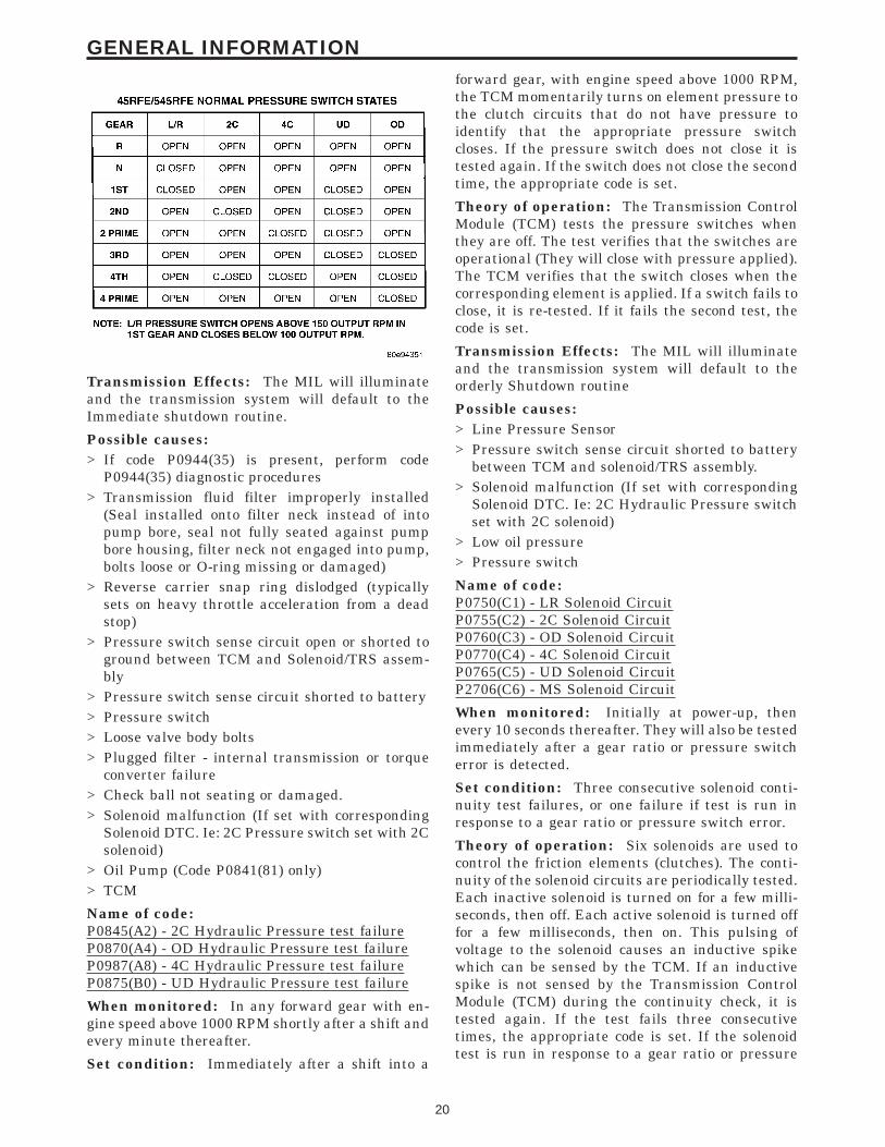
Transmission Effects: The MIL will illuminateand the transmission system will default to theImmediate shutdown routine.
Possible causes:> If code P0944(35) is present, perform code
P0944(35) diagnostic procedures> Transmission fluid filter improperly installed
(Seal installed onto filter neck instead of intopump bore, seal not fully seated against pumpbore housing, filter neck not engaged into pump,bolts loose or O-ring missing or damaged)
> Reverse carrier snap ring dislodged (typicallysets on heavy throttle acceleration from a deadstop)
> Pressure switch sense circuit open or shorted toground between TCM and Solenoid/TRS assem-bly
> Pressure switch sense circuit shorted to battery> Pressure switch> Loose valve body bolts> Plugged filter - internal transmission or torque
converter failure> Check ball not seating or damaged.> Solenoid malfunction (If set with corresponding
Solenoid DTC. Ie: 2C Pressure switch set with 2Csolenoid)
> Oil Pump (Code P0841(81) only)> TCM
Name of code:P0845(A2) - 2C Hydraulic Pressure test failureP0870(A4) - OD Hydraulic Pressure test failureP0987(A8) - 4C Hydraulic Pressure test failureP0875(B0) - UD Hydraulic Pressure test failure
When monitored: In any forward gear with en-gine speed above 1000 RPM shortly after a shift andevery minute thereafter.
Set condition: Immediately after a shift into a
forward gear, with engine speed above 1000 RPM,the TCM momentarily turns on element pressure tothe clutch circuits that do not have pressure toidentify that the appropriate pressure switchcloses. If the pressure switch does not close it istested again. If the switch does not close the secondtime, the appropriate code is set.
Theory of operation: The Transmission ControlModule (TCM) tests the pressure switches whenthey are off. The test verifies that the switches areoperational (They will close with pressure applied).The TCM verifies that the switch closes when thecorresponding element is applied. If a switch fails toclose, it is re-tested. If it fails the second test, thecode is set.
Transmission Effects: The MIL will illuminateand the transmission system will default to theorderly Shutdown routine
Possible causes:> Line Pressure Sensor> Pressure switch sense circuit shorted to battery
between TCM and solenoid/TRS assembly.> Solenoid malfunction (If set with corresponding
Solenoid DTC. Ie: 2C Hydraulic Pressure switchset with 2C solenoid)
> Low oil pressure> Pressure switch
Name of code:P0750(C1) - LR Solenoid CircuitP0755(C2) - 2C Solenoid CircuitP0760(C3) - OD Solenoid CircuitP0770(C4) - 4C Solenoid CircuitP0765(C5) - UD Solenoid CircuitP2706(C6) - MS Solenoid Circuit
When monitored: Initially at power-up, thenevery 10 seconds thereafter. They will also be testedimmediately after a gear ratio or pressure switcherror is detected.
Set condition: Three consecutive solenoid conti-nuity test failures, or one failure if test is run inresponse to a gear ratio or pressure switch error.
Theory of operation: Six solenoids are used tocontrol the friction elements (clutches). The conti-nuity of the solenoid circuits are periodically tested.Each inactive solenoid is turned on for a few milli-seconds, then off. Each active solenoid is turned offfor a few milliseconds, then on. This pulsing ofvoltage to the solenoid causes an inductive spikewhich can be sensed by the TCM. If an inductivespike is not sensed by the Transmission ControlModule (TCM) during the continuity check, it istested again. If the test fails three consecutivetimes, the appropriate code is set. If the solenoidtest is run in response to a gear ratio or pressure
20
GENERAL INFORMATION
switch error, one failure will result in setting theappropriate code.
Transmission Effects: The MIL will illuminateand the transmission system will default to theImmediate Shutdown routine.
Possible causes:> Open or shorted solenoid circuit(s) between TCM
and solenoid/TRS assembly.> Open ground circuit.> TCM connector problems.> Solenoid/TRS connector problem.> Solenoid/TRS assembly.> TCM
Name of code:P0868(C9) - Line Pressure LowP0869(CB) - Line Pressure HighP0932(CA) - Line Pressure Sensor Circuit faultP0934(CC) - Line Pressure Sensor LowP0935(CD) - Line Pressure Sensor High
P0932- When monitored: Continuously whiledriving in a forward gear.
Set condition: The TCM continuously monitorstransducer Line Pressure Output and compares itto Desired Line Pressure. If the difference betweentransducer Line Pressure output and Desired LinePressure is 10 PSI or greater, the DTC will set inapproximately 3.57 seconds.
P0934- When monitored: Set condition: Contin-uously with engine running and Output Speedgreater than 390 RPM.
Set condition: This DTC will set when the LinePressure Sensor output is less than 0.35 volts for1.4 seconds.
P0935- When monitored: Continuously with en-gine running, Output Speed greater than 390 RPMand Desired Line Pressure less than 200.
Set condition: This DTC will set if is Line Pres-sure Sensor Output is greater than 4.75 volts for 1.4seconds.
P0868- When monitored: Continuously whiledriving in a forward gear.
Set condition: The TCM continuously monitorstransducer Line Pressure Output and compares itto Desired Line Pressure. If transducer Line Pres-sure Output is more than 10 PSI below DesiredLine Pressure, the DTC will set in approximately2.1 seconds.
P0869- When monitored: Continuously whiledriving in a forward gear.
Set condition: The TCM continuously monitorstransducer Line Pressure Output and compares itto Desired Line Pressure. If transducer Line Pres-sure Output is more than 10 PSI above Desired
Line Pressure, the DTC will set in approximately3.57 seconds.
Theory of operation: Line pressure is controlledby the TCM. It is measured by the Line PressureSensor (LPS) and regulation is achieved by chang-ing the duty cycle of the Pressure Control Solenoid(PCS). (5% duty cycle = solenoid off = max linepressure, 62% duty cycle = solenoid on = min linepressure). The TCM calculates the desired linepressure based on inputs from the transmission andengine. The TCM calculates torque input to thetransmission and uses it as the primary input to thedesired line pressure calculation. This is calledTorque Based Line Pressure. In addition, the linepressure is set to a preset level 827 or 931kPa (120or 135 PSI) during shifts and in Park and Neutral toensure consistent shift quality. The desired linepressure is continuously being compared to theactual line pressure. If the actual line pressure isconsistently higher than the target, the line pres-sure high DTC P0869(CB) will be set. If the actualline pressure is consistently lower than the target,the line pressure low DTC P0868(C9) will be set. Ifit is consistently out of range, but not consistentlyhigh or low, it is considered out of range and the linepressure error DTC P0932(CA) will be set.
Transmission Effects: The Transmission systemwill default to open loop line pressure control re-sulting in a fixed PCS duty cycle. This duty cyclewill change slightly depending on temperature andcurrent gear.
Possible causes:> Sticking Regulator Valve> Pressure Control Solenoid> Line Pressure Sensor.> Oil pump> Plugged Filter> 5V supply circuit to Line Pressure Sensor open
(Sensor reading will display a constant valuebetween 586 and 655 kPa (85 and 95 PSI)
> LPS signal circuit shorted to ground, shorted tovoltage, or open.
> 5-volt supply circuit shorted to ground, shorted tovoltage, or open.
> Open sensor ground> TCM
Name of code: P2620(2C) - ETC Throttle PositionOutput Circuit
When monitored: Continuously with the ignitionon.
Set condition: The Pulse Accumulator InputCounter (PAIC) is a hardwired frequency modu-lated signal that the TCM receives from the enginecontroller. When the frequency transmitted exceeds
21
GENERAL INFORMATION
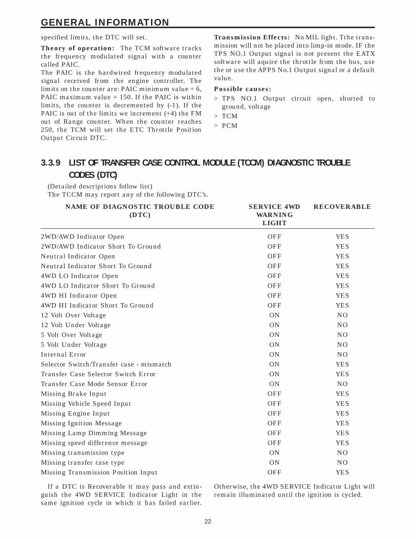
specified limits, the DTC will set.
Theory of operation: The TCM software tracksthe frequency modulated signal with a countercalled PAIC.The PAIC is the hardwired frequency modulatedsignal received from the engine controller. Thelimits on the counter are: PAIC minimum value = 6,PAIC maximum value = 150. If the PAIC is withinlimits, the counter is decremented by (-1). If thePAIC is out of the limits we increment (+4) the FMout of Range counter. When the counter reaches250, the TCM will set the ETC Throttle PositionOutput Circuit DTC.
Transmission Effects: No MIL light. Tthe trans-mission will not be placed into limp-in mode. IF theTPS NO.1 Output signal is not present the EATXsoftware will aquire the throttle from the bus, usethe or use the APPS No.1 Output signal or a defaultvalue.
Possible causes:> TPS NO.1 Output circuit open, shorted to
ground, voltage> TCM> PCM
3.3.9 LIST OF TRANSFER CASE CONTROL MODULE (TCCM) DIAGNOSTIC TROUBLECODES (DTC)
(Detailed descriptions follow list)The TCCM may report any of the following DTC’s.
NAME OF DIAGNOSTIC TROUBLE CODE(DTC)
SERVICE 4WDWARNING
LIGHT
RECOVERABLE
2WD/AWD Indicator Open OFF YES2WD/AWD Indicator Short To Ground OFF YESNeutral Indicator Open OFF YESNeutral Indicator Short To Ground OFF YES4WD LO Indicator Open OFF YES4WD LO Indicator Short To Ground OFF YES4WD HI Indicator Open OFF YES4WD HI Indicator Short To Ground OFF YES12 Volt Over Voltage ON NO12 Volt Under Voltage ON NO5 Volt Over Voltage ON NO5 Volt Under Voltage ON NOInternal Error ON NOSelector Switch/Transfer case - mismatch ON YESTransfer Case Selector Switch Error ON YESTransfer Case Mode Sensor Error ON NOMissing Brake Input OFF YESMissing Vehicle Speed Input OFF YESMissing Engine Input OFF YESMissing Ignition Message OFF YESMissing Lamp Dimming Message OFF YESMissing speed difference message OFF YESMissing transmission type ON NOMissing transfer case type ON NOMissing Transmission Position Input OFF YES
If a DTC is Recoverable it may pass and extin-guish the 4WD SERVICE Indicator Light in thesame ignition cycle in which it has failed earlier.
Otherwise, the 4WD SERVICE Indicator Light willremain illuminated until the ignition is cycled.
22
GENERAL INFORMATION
Transfer Case Control Module (TCCM) Diag-nostic Trouble Code (DTC) Descriptions
Name of DTC: 2WD/AWD Indicator Open
When monitored: Continuously with key on.
Set condition: This Diagnostic Trouble Code(DTC) is set whenever Transfer Case Control Mod-ule (TCCM) detects an open in the 2WD / AWDindicator circuit.
Theory of operation: The TCCM supports diag-nostics to identify any open or short in an LEDcircuit. The open detection will only be functionalduring full illumination.
Name of DTC: 2WD/AWD Indicator Short ToGround
When monitored: Continuously with key on.
Set condition: This Diagnostic Trouble Code(DTC) is set whenever Transfer Case Control Mod-ule (TCCM) detects short to ground in the 2WD /AWD indicator circuit.
Theory of operation: The TCCM supports diag-nostics to identify any open or short in an LEDcircuit. The open detection will only be functionalduring full illumination.
Name of DTC: Neutral Indicator Open
When monitored: Continuously with key on.
Set condition: This Diagnostic Trouble Code(DTC) is set whenever Transfer Case Control Mod-ule (TCCM) detects an open in the Neutral indica-tor circuit.
Theory of operation: The TCCM supports diag-nostics to identify any open or short in an LEDcircuit. The open detection will only be functionalduring full illumination.
Name of DTC: Neutral Indicator Short ToGround
When monitored: Continuously with key on.
Set condition: This Diagnostic Trouble Code(DTC) is set whenever Transfer Case Control Mod-ule (TCCM) detects short to ground in the Neutralindicator circuit.
Theory of operation: The TCCM supports diag-nostics to identify any open or short in an LEDcircuit. The open detection will only be functionalduring full illumination.
Name of DTC: 4WD LO Indicator Open
When monitored: Continuously with key on.
Set condition: This Diagnostic Trouble Code(DTC) is set whenever Transfer Case Control Mod-ule (TCCM) detects an open in the 4WD LO indica-tor circuit.
Theory of operation: The TCCM supports diag-
nostics to identify any open or short in an LEDcircuit. The open detection will only be functionalduring full illumination.
Name of DTC: 4WD LO Indicator Short ToGround
When monitored: Continuously with key on.
Set condition: This Diagnostic Trouble Code(DTC) is set whenever Transfer Case Control Mod-ule (TCCM) detects short to ground in 4WD LOindicator circuit.
Theory of operation: The TCCM supports diag-nostics to identify any open or short in an LEDcircuit. The open detection will only be functionalduring full illumination.
Name of DTC: 4WD HI Indicator Open
When Monitored: Continuously with key on.
Set Condition: This Diagnostic Trouble Code(DTC) is set whenever Transfer Case Control Mod-ule (TCCM) detects an open in the 4WD HI indica-tor circuit.
Theory of operation: The TCCM supports diag-nostics to identify any open or short in an LEDcircuit. The open detection will only be functionalduring full illumination.
Name of DTC: 4WD HI Indicator Short ToGround
When monitored: Continuously with key on.
Set condition: This Diagnostic Trouble Code(DTC) is set whenever Transfer Case Control Mod-ule (TCCM) detects short to ground in the 4WD HIindicator circuit.
Theory of operation: The TCCM supports diag-nostics to identify any open or short in an LEDcircuit. The open detection will only be functionalduring full illumination.
Name of DTC: 12 Volt Over Voltage
When monitored: Continuously with key on.
Set condition: This Diagnostic Trouble Code(DTC) is set whenever Transfer Case Control Mod-ule (TCCM) detects that the system power hasexceeded 16.0 volts for 2 seconds.
Theory of operation: If the TCCM detects thatsystem power has exceeded the 16 volt threshold for2 seconds, transfer case shifts and DTCs will not beallowed but, the TCCM communication will still beenabled.
Name of DTC: 12 Volt Under Voltage
When monitored: Continuously with key on.
Set condition: This Diagnostic Trouble Code(DTC) is set whenever Transfer Case Control Mod-ule (TCCM) detects that the system power hasdropped below 9.0 volts for 2 seconds.
23
GENERAL INFORMATION
Theory of operation: If the TCCM detects thatsystem power has dropped below the 9 volt thresh-old for 2 seconds, transfer case shifts and DTCs willnot be allowed but, the TCCM communication willstill be enabled.
Name of DTC: 5 Volt Over Voltage
When monitored: Continuously with key on.
Set condition: This Diagnostic Trouble Code(DTC) is set whenever Transfer Case Control Mod-ule (TCCM) detects that the Mode Sensor andSelector Switch supply power has exceeded 6.0 voltsfor 20 seconds.
Theory of operation: If the TCCM detects thatpower has exceeded the high voltage threshold for 2seconds, transfer case shifts will not be allowed butTCCM communication will still be enabled.
Name of DTC: 5 Volt Under Voltage
When monitored: Continuously with key on.
Set condition: This Diagnostic Trouble Code(DTC) is set whenever Transfer Case Control Mod-ule (TCCM) detects that the Mode Sensor andSelector Switch supply power has dropped below4.0 volts for 20 seconds.
Theory of operation: If the TCCM detects thatpower has dropped below the low voltage thresholdfor 2 seconds, transfer case shifts will not be al-lowed but TCCM communication will still be en-abled.
Name of DTC: Internal Error
When monitored: Continuously with key on.
Set condition: This DTC is set whenever theTransfer Case Control Module (TCCM) detects anEEPROM Checksum Error, Flash Checksum error,or RAM Integrity error.
Theory of operation: The TCCM constantlymonitors its internal processes if an error occurs aDTC will be set. This is done to ensure propertransfer case operation.
Name of DTC: Transfer Case Selector SwitchError
When Monitored: Continuously with key on.
Set condition: This Diagnostic Trouble Code(DTC) is set whenever Transfer Case Control Mod-ule (TCCM) detects a Selector Switch input of lessthan 250° or more than 14.5k(. This DiagnosticTrouble Code (DTC) will also set whenever TCCMdetects a Selector Switch input of .25 volts or less,or 5 volts or more.
Theory of operation: The TCCM is capable ofdiagnosing an out of range selector switch.The TCCM has a defined operation status based onselector switch resistances and voltage. If the
TCCM senses an out of range resistance or voltagetransfer case shifts will not be allowed
Name of DTC: Transfer Case Mode Sensor Error
When monitored: Continuously with key on.
Set condition : This Diagnostic Trouble Code(DTC) is set whenever Transfer Case Control Mod-ule (TCCM) detects any of the following conditions:1. The Mode Sensor has an incorrect transition
during a shift, then attempts and fails 2 times todefault to 4WD HI position.
2. An invalid Mode Sensor position.3. The Mode Sensor has four bad transitions dur-
ing one ignition cycle.
Theory of operation: The mode sensor consistsof a magnetic ring and four hall effect transistorswhich convert motor shaft position into a codedsignal.
Name of DTC: Missing Brake Input
When monitored: Continuously with key on.
Set condition: This Diagnostic Trouble Code(DTC) is set whenever Transfer Case Control Mod-ule (TCCM) stops receiving this message for 5seconds.
Theory of operation: This data is necessary forthe shifts involving neutral.
Name of DTC: Missing Vehicle Speed Input
When monitored: Continuously with key on.
Set condition: This Diagnostic Trouble Code(DTC) is set whenever Transfer Case Control Mod-ule (TCCM) stops receiving this message for 5seconds.
Theory of operation: This data is necessary forrange shifts and shifts involving neutral.
Name of DTC: Missing Engine Input
When monitored: Continuously with key on.
Set condition: This Diagnostic Trouble Code(DTC) is set whenever Transfer Case Control Mod-ule (TCCM) stops receiving this message for 5seconds.
Theory of operation: This data is necessary forrange shifts and shifts involving neutral.
Name of DTC: Missing Ignition Message
When monitored: Continuously with key on.
Set condition: This Diagnostic Trouble Code(DTC) is set whenever Transfer Case Control Mod-ule (TCCM) stops receiving this message for 5seconds.
Theory of operation: This data is required for alltransfer case shifts.
24
GENERAL INFORMATION
Name of DTC: Missing Lamp Dimming Message
When monitored: Continuously with key on.
Set condition: This Diagnostic Trouble Code(DTC) is set whenever Transfer Case Control Mod-ule (TCCM) stops receiving this message for 5seconds.
Theory of operation: This information is re-quired to ensure that the selector switch LEDs areilluminated to the correct intensity (the LEDs arepulse width modulated to control brightness). If thisinformation is lost the TCCM will set a DTC andilluminate the LEDs to full brightness.
Name of DTC: Missing Transmission PositionInput
When monitored: Continuously with key on.
Set condition: This Diagnostic Trouble Code(DTC) is set whenever Transfer Case Control Mod-ule (TCCM) stops receiving this message for 5seconds.
Theory of operation: This data is required forrange shifts and shifts involving neutral.
Name of DTC: Selector Switch/Transfer case -mismatch
When monitored: Continuously with key on.
Set condition: This Diagnostic Trouble Code(DTC) is set whenever Transfer Case Control Mod-ule (TCCM) senses a mismatch between the selectorswitch and the transfer case.
Theory of operation: The selector switch mustmatch the correct transfer case for proper opera-tion.Each transfer case selector switch supplies a resis-tance to the TCCM. If the supplied resistance fromthe selector switch does not match the transfer casetype a the TCCM will set a DTC and proper transfercase operation will not be allowed.
Name of DTC: Missing transfer case type
When monitored: Continuously with key on.
Set condition: This Diagnostic Trouble Code(DTC) is set whenever Transfer Case Control Mod-ule (TCCM) stops receiving this message for 5seconds when the transfer case type has not beenread from the vehicles bus.
Theory of operation: This data is necessary tomatch the selector switch to the transfer case typefor proper transfer case operation.
Name of DTC: Missing transmission type
When monitored: Continuously with key on.
Set condition: This Diagnostic Trouble Code(DTC) is set whenever Transfer Case Control Mod-ule (TCCM) stops receiving this message for 5seconds or when the transmission type has not been
read from the vehicles bus since module installa-tion.
Name of DTC: Missing speed difference message
When monitored: Continuously with key on.
Set condition: This Diagnostic Trouble Code(DTC) is set whenever Transfer Case Control Mod-ule (TCCM) stops receiving this message from theABS/RWAL module for 5 seconds.
Theory of operation: The wheel speed informa-tion from the ABS/RWAL module is required toprevent aggressive transfer case shifting. TheTransfer Case Control Module will only allow shiftswhen the speed difference between the front andrear wheels is less than 13 MPH.
3.3.10 QUICK LEARNThe Quick Learn function customizes adaptive
parameters of the TCM to the transmission charac-teristics of a vehicle. This gives the customer im-proved ‘‘as received’’ shift quality compared to theinitial parameters stored in the TCM.
Notes about Quick Learn FeaturesThe nature of the Quick Learn function requires
that certain features must be taken into consider-ation.> Quick Learn should generally not be used as a
repair procedure unless directed by a repair ordiagnostic procedure. If the transmission systemis exhibiting a problem that you think is causedby an invalid CVI, you should try to relearn thevalue by performing the appropriate driving ma-neuver . In most cases, if a Quick Learn makes avehicle shift better, the vehicle will return withthe same problem.
> Before performing Quick Learn, it is imperativethat the vehicle be shifted into OD with theengine running and the oil level set to the correctlevel. This step will purge air from the clutchcircuits to prevent erroneous clutch volume val-ues which could cause poor initial shift quality.Cycle the transmission through all gears 2-3times immediately before performing QuickLearn. For best results, Quick Learn should berun with the transmission sump temperature >90°F.
> If an unused TCM is installed on a vehicle with aHOT engine, Quick Learn will cause the TCM toreport a cold calculated oil temperature. Thisrequires monitoring the calculated oil tempera-ture using the DRBIIIt. If the temperature isbelow 16° C (60° F), the transmission must berun at idle or driven in gear until it goes above16° C (60° F). If the temperature is above 93° C(200° F), the transmission must cool to below93° C (200° F).
25
GENERAL INFORMATION
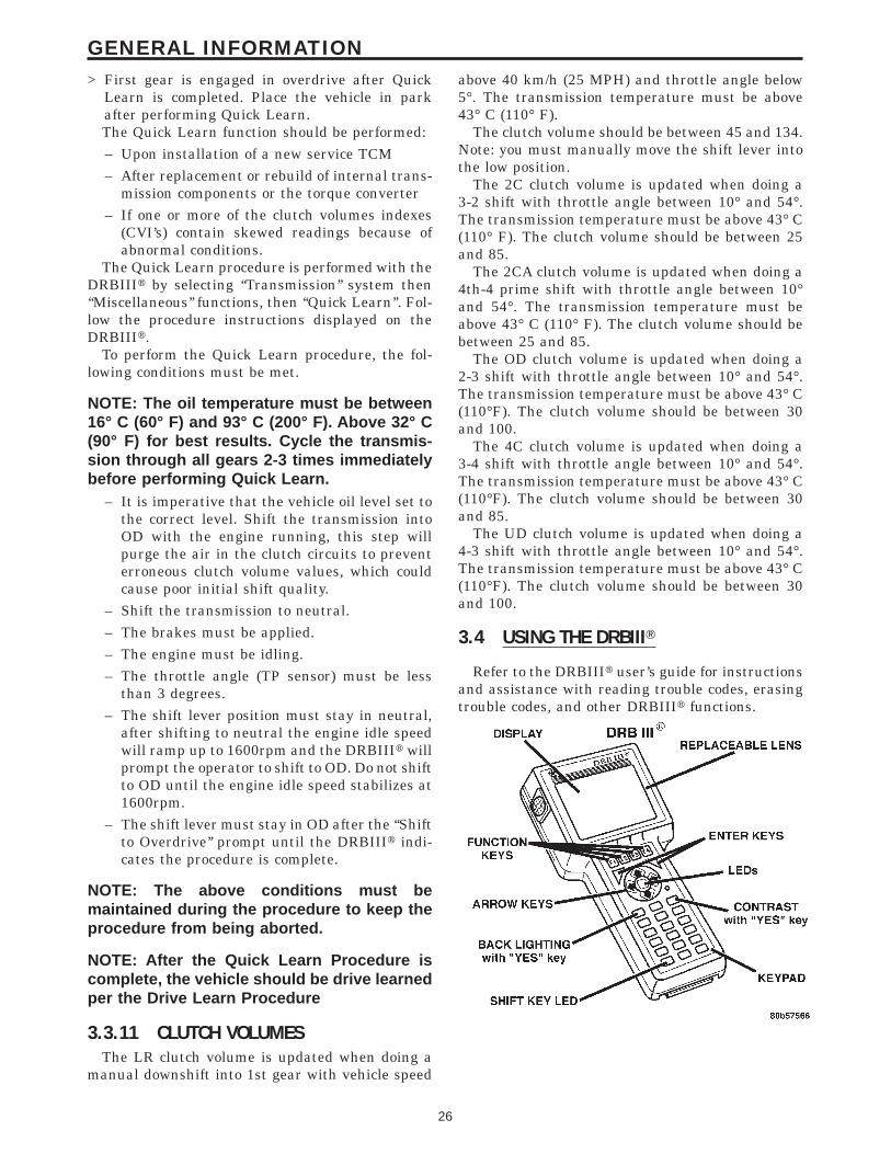
> First gear is engaged in overdrive after QuickLearn is completed. Place the vehicle in parkafter performing Quick Learn.The Quick Learn function should be performed:– Upon installation of a new service TCM– After replacement or rebuild of internal trans-
mission components or the torque converter– If one or more of the clutch volumes indexes
(CVI’s) contain skewed readings because ofabnormal conditions.
The Quick Learn procedure is performed with theDRBIIIt by selecting ‘‘Transmission’’ system then‘‘Miscellaneous’’ functions, then ‘‘Quick Learn’’. Fol-low the procedure instructions displayed on theDRBIIIt.
To perform the Quick Learn procedure, the fol-lowing conditions must be met.
NOTE: The oil temperature must be between16° C (60° F) and 93° C (200° F). Above 32° C(90° F) for best results. Cycle the transmis-sion through all gears 2-3 times immediatelybefore performing Quick Learn.
– It is imperative that the vehicle oil level set tothe correct level. Shift the transmission intoOD with the engine running, this step willpurge the air in the clutch circuits to preventerroneous clutch volume values, which couldcause poor initial shift quality.
– Shift the transmission to neutral.– The brakes must be applied.– The engine must be idling.– The throttle angle (TP sensor) must be less
than 3 degrees.– The shift lever position must stay in neutral,
after shifting to neutral the engine idle speedwill ramp up to 1600rpm and the DRBIIIt willprompt the operator to shift to OD. Do not shiftto OD until the engine idle speed stabilizes at1600rpm.
– The shift lever must stay in OD after the ‘‘Shiftto Overdrive’’ prompt until the DRBIIIt indi-cates the procedure is complete.
NOTE: The above conditions must bemaintained during the procedure to keep theprocedure from being aborted.
NOTE: After the Quick Learn Procedure iscomplete, the vehicle should be drive learnedper the Drive Learn Procedure
3.3.11 CLUTCH VOLUMESThe LR clutch volume is updated when doing a
manual downshift into 1st gear with vehicle speed
above 40 km/h (25 MPH) and throttle angle below5°. The transmission temperature must be above43° C (110° F).
The clutch volume should be between 45 and 134.Note: you must manually move the shift lever intothe low position.
The 2C clutch volume is updated when doing a3-2 shift with throttle angle between 10° and 54°.The transmission temperature must be above 43° C(110° F). The clutch volume should be between 25and 85.
The 2CA clutch volume is updated when doing a4th-4 prime shift with throttle angle between 10°and 54°. The transmission temperature must beabove 43° C (110° F). The clutch volume should bebetween 25 and 85.
The OD clutch volume is updated when doing a2-3 shift with throttle angle between 10° and 54°.The transmission temperature must be above 43° C(110°F). The clutch volume should be between 30and 100.
The 4C clutch volume is updated when doing a3-4 shift with throttle angle between 10° and 54°.The transmission temperature must be above 43° C(110°F). The clutch volume should be between 30and 85.
The UD clutch volume is updated when doing a4-3 shift with throttle angle between 10° and 54°.The transmission temperature must be above 43° C(110°F). The clutch volume should be between 30and 100.
3.4 USING THE DRBIIIT
Refer to the DRBIIIt user’s guide for instructionsand assistance with reading trouble codes, erasingtrouble codes, and other DRBIIIt functions.
26
GENERAL INFORMATION
3.5 DRBIIIT ERROR MESSAGES
Under normal operation, the DRBIIIt will dis-play one of only two error messages:
– User-Requested WARM Boot– User-Requested COLD BootIf the DRBIIIt should display any other error
message, record the entire display and call theS.T.A.R. Center.
3.5.1 DRBIIIT DOES NOT POWER UP(BLANK SCREEN)
If the LED’s do not light or no sound is emitted atstart up, check for loose cable connections or a badcable. Check the vehicle battery voltage. A mini-mum of 11 volts is required to adequately power theDRBIIIt.
If all connections are proper between theDRBIIIt and the vehicle or other devices, and thevehicle battery is fully charged, an inoperativeDRBIIIt may be the result of faulty cable or vehiclewiring. For a blank screen, refer to the appropriateBody Diagnostic manual.
3.5.2 DISPLAY IS NOT VISIBLELow temperatures will affect the visibility of the
display. Adjust the contrast to compensate for thiscondition.
3.5.3 SOME DISPLAY ITEMS READ ‘‘---’’This is caused by the scrolling the DRBIIIt dis-
play a single line up or down. The line which wasscrolled onto the screen might read ‘‘---’’. Use thepage down or page up function to display theinformation.
3.6 TRANSMISSION SIMULATOR (MILLERTOOL # 8333) AND ELECTRONICTRANSMISSION ADAPTER KIT(MILLER TOOL #8333-1A)
NOTE: Remove the starter Relay when usingthe transmission simulator*Failure to remove the Starter Relay cancause a PCM - No Response condition.*The removal of the Starter Relay will alsoprevent the engine from starting in gear.*The Transmission Simulator will notaccurately diagnose intermittent faults
The transmission simulator, simply put, is anelectronic device that simulates the electronic func-tions of any EATX or NGC controlled transmission.The Simulators basic function is to aid the techni-cian in determining if an internal transmission
problem exists or if the problem resides in thevehicle wiring or control module. It is only useful forelectrical problems. It will not aid in the diagnosisof a failed mechanical component, but it can tell youthat the control module and wiring are workingproperly and that the problem is internal to thetransmission.
The ignition switch should be in the lock positionbefore attempting to install the simulator. Followall instructions included with the simulator. If thefeedback from the simulator is in doubt, you canverify it’s operation by installing it on a known goodvehicle. A ‘‘known good vehicle’’ would be defined asa vehicle that does not set any DTC’s and drives andshifts as expected.
One important point to remember is that theSimulator receives it’s power from the Trans RelayOutput circuit. If the transmission system is inLimp-in (Relay open), the simulator will not oper-ate. This is not really an indication of a problem,but an additional symptom. If the simulator doesnot power up (‘‘P’’ led lit), this is an indication thatthe problem is still present with the simulatorhooked up. This indicates that the problem is in thewiring or control module and not the transmission.
Miller Tool # 8333-1A consists of the adaptercables and overlay necessary to adapt the simulatorto TE/AE/LE/RLE transmissions.
4.0 DISCLAIMERS, SAFETY,AND WARNINGS
4.1 DISCLAIMERS
All information, illustrations, and specificationscontained in this manual are based on the latestinformation available at the time of publication.The right is reserved to make changes at any timewithout notice.
4.2 SAFETY
4.2.1 TECHNICIAN SAFETY INFORMATION
WARNING: ENGINES PRODUCE CARBONMONOXIDE THAT IS ODORLESS, CAUSESSLOWER REACTION TIME, AND CAN LEADTO SERIOUS INJURY. WHEN THE ENGINE ISOPERATING KEEP SERVICE AREAS WELLVENTILATED OR ATTACH THE VEHICLEEXHAUST SYSTEM TO THE SHOP EXHAUSTREMOVAL SYSTEM.
Set the parking brake and block the wheels beforetesting or repairing the vehicle. If is especially
27
GENERAL INFORMATION
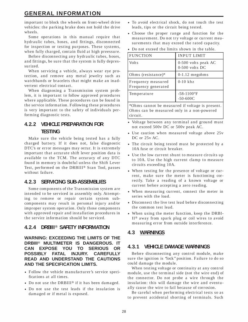
important to block the wheels on front-wheel drivevehicles: the parking brake does not hold the drivewheels.
Some operations in this manual require thathydraulic tubes, hoses, and fittings, disconnectedfor inspection or testing purposes. These systems,when fully charged, contain fluid at high preessure.
Before disconnecting any hydraulic tubes, hoses,and fittings, be sure that the system is fully depres-surized.
When servicing a vehicle, always wear eye pro-tection, and remove any metal jewelry such aswatchbands or bracelets that might make an inad-vertent electrical contact.
When diagnosing a Transmission system prob-lem, it is important to follow approved procedureswhere applicable. These procedures can be found inthe service information. Following these proceduresis very important to the safety of individuals per-forming diagnostic tests.
4.2.2 VEHICLE PREPARATION FORTESTING
Make sure the vehicle being tested has a fullycharged battery. If it does not, false diagnosticDTC’s or error messages may occur. It is extremelyimportant that accurate shift lever position data isavailable to the TCM. The accuracy of any DTCfound in memory is doubtful unless the Shift LeverTest, performed on the DRBIIIt Scan Tool, passeswithout failure.
4.2.3 SERVICING SUB-ASSEMBLIESSome components of the Transmission system are
intended to be serviced in assembly only. Attempt-ing to remove or repair certain system sub-components may result in personal injury and/orimproper system operation. Only those componentswith approved repair and installation procedures inthe service information should be serviced.
4.2.4 DRBIIIT SAFETY INFORMATION
WARNING: EXCEEDING THE LIMITS OF THEDRBIIIT MULTIMETER IS DANGEROUS. ITCAN EXPOSE YOU TO SERIOUS ORPOSSIBLY FATAL INJURY. CAREFULLYREAD AND UNDERSTAND THE CAUTIONSAND THE SPECIFICATION LIMITS.
• Follow the vehicle manufacturer’s service speci-fications at all times.
• Do not use the DRBIIIt if it has been damaged.• Do not use the test leads if the insulation is
damaged or if metal is exposed.
• To avoid electrical shock, do not touch the testleads, tips or the circuit being tested.
• Choose the proper range and function for themeasurement. Do not try voltage or current mea-surements that may exceed the rated capacity.
• Do not exceed the limits shown in the table.
FUNCTION INPUT LIMIT
Volts 0-500 volts peak AC0-500 volts DC
Ohms (resistance)* 0-1.12 megohms
Frequency measuredFrequency generated
0-10 khz
Temperature -58-1100°F-50-600C
*Ohms cannot be measured if voltage is present.Ohms can be measured only in a non-poweredcircuit.
• Voltage between any terminal and ground mustnot exceed 500v DC or 500v peak AC.
• Use caution when measured voltage above 25vDC or 25v AC.
• The circuit being tested must be protected by a10A fuse or circuit breaker.
• Use the low current shunt to measure circuits upto 10A. Use the high current clamp to measurecircuits exceeding 10A.
• When testing for the presence of voltage or cur-rent, make sure the meter is functioning cor-rectly. Take a reading of a known voltage orcurrent before accepting a zero reading.
• When measuring current, connect the meter inseries with the load.
• Disconnect the live test lead before disconnectingthe common test lead.
• When using the meter function, keep the DRBI-IIt away from spark plug or coil wires to avoidmeasuring error from outside interference.
4.3 WARNINGS
4.3.1 VEHICLE DAMAGE WARNINGSBefore disconnecting any control module, make
sure the ignition is ‘‘lock’’ position. Failure to do socould damage the module.
When testing voltage or continuity at any controlmodule, use the terminal side (not the wire end) ofthe connector. Do not probe a wire through theinsulation: this will damage the wire and eventu-ally cause the wire to fail because of corrosion.
Be careful when performing electrical tests so asto prevent accidental shorting of terminals. Such
28
GENERAL INFORMATION
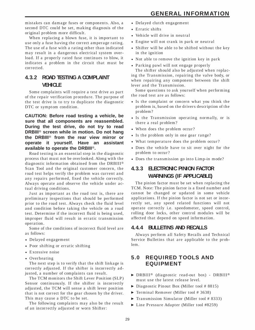
mistakes can damage fuses or components. Also, asecond DTC could be set, making diagnosis of theoriginal problem more difficult.
When replacing a blown fuse, it is important touse only a fuse having the correct amperage rating.The use of a fuse with a rating other than indicatedmay result in a dangerous electrical system over-load. If a properly rated fuse continues to blow, itindicates a problem in the circuit that must becorrected.
4.3.2 ROAD TESTING A COMPLAINTVEHICLE
Some complaints will require a test drive as partof the repair verification procedure. The purpose ofthe test drive is to try to duplicate the diagnosticDTC or symptom condition.
CAUTION: Before road testing a vehicle, besure that all components are reassembled.During the test drive, do not try to readDRBIIIT screen while in motion. Do not hangthe DRBIII T from the rear view mirror oroperate it yourself. Have an assistantavailable to operate the DRBIII T.
Road testing is an essential step in the diagnosticprocess that must not be overlooked. Along with thediagnostic information obtained from the DRBIIItScan Tool and the original customer concern, theroad test helps verify the problem was current andany repairs performed, fixed the vehicle correctly.Always operate and observe the vehicle under ac-tual driving conditions.
Just as important as the road test is, there arepreliminary inspections that should be performedprior to the road test. Always check the fluid leveland condition before taking the vehicle on a roadtest. Determine if the incorrect fluid is being used,improper fluid will result in erratic transmissionoperation.
Some of the conditions of incorrect fluid level areas follows:• Delayed engagement• Poor shifting or erratic shifting• Excessive noise• Overheating
The next step is to verify that the shift linkage iscorrectly adjusted. If the shifter is incorrectly ad-justed, a number of complaints can result.
The TCM monitors the Shift Lever Position (SLP)Sensor continuously. If the shifter is incorrectlyadjusted, the TCM will sense a shift lever positionthat is not correct for the gear chosen by the driver.This may cause a DTC to be set.
The following complaints may also be the resultof an incorrectly adjusted or worn Shifter:
• Delayed clutch engagement• Erratic shifts• Vehicle will drive in neutral• Engine will not crank in park or neutral• Shifter will be able to be shifted without the key
in the ignition• Not able to remove the ignition key in park• Parking pawl will not engage properly
The shifter should also be adjusted when replac-ing the Transmission, repairing the valve body, orwhen repairing any component between the shiftlever and the Transmission.
Some questions to ask yourself when performingthe road test are as follows:• Is the complaint or concern what you think the
problem is, based on the drivers description of theproblem?
• Is the Transmission operating normally, or isthere a real problem?
• When does the problem occur?• Is the problem only in one gear range?• What temperature does the problem occur?• Does the vehicle have to sit over night for the
problem to occur?• Does the transmission go into Limp-in mode?
4.3.3 ELECTRONIC PINION FACTORWARNINGS (IF APPLICABLE)
The pinion factor must be set when replacing theTCM. Note: The pinion factor is a fixed number andcannot be changed or updated in some vehicleapplications. If the pinion factor is not set or incor-rectly set, any speed related functions will notoperate correctly i.e. speedometer, speed control,rolling door locks, other control modules will beaffected that depend on speed information.
4.4.4 BULLETINS AND RECALLSAlways perform all Safety Recalls and Technical
Service Bulletins that are applicable to the prob-lem.
5.0 REQUIRED TOOLS ANDEQUIPMENT
c DRBIIIt (diagnostic read-out box) - DRBIIItmust use the latest release level.
c Diagnostic Pinout Box (Miller tool # 8815)c Terminal Remover (Miller tool # 3638)c Transmission Simulator (Miller tool # 8333)c Line Pressure Adapter (Miller tool #8259)
29
GENERAL INFORMATION
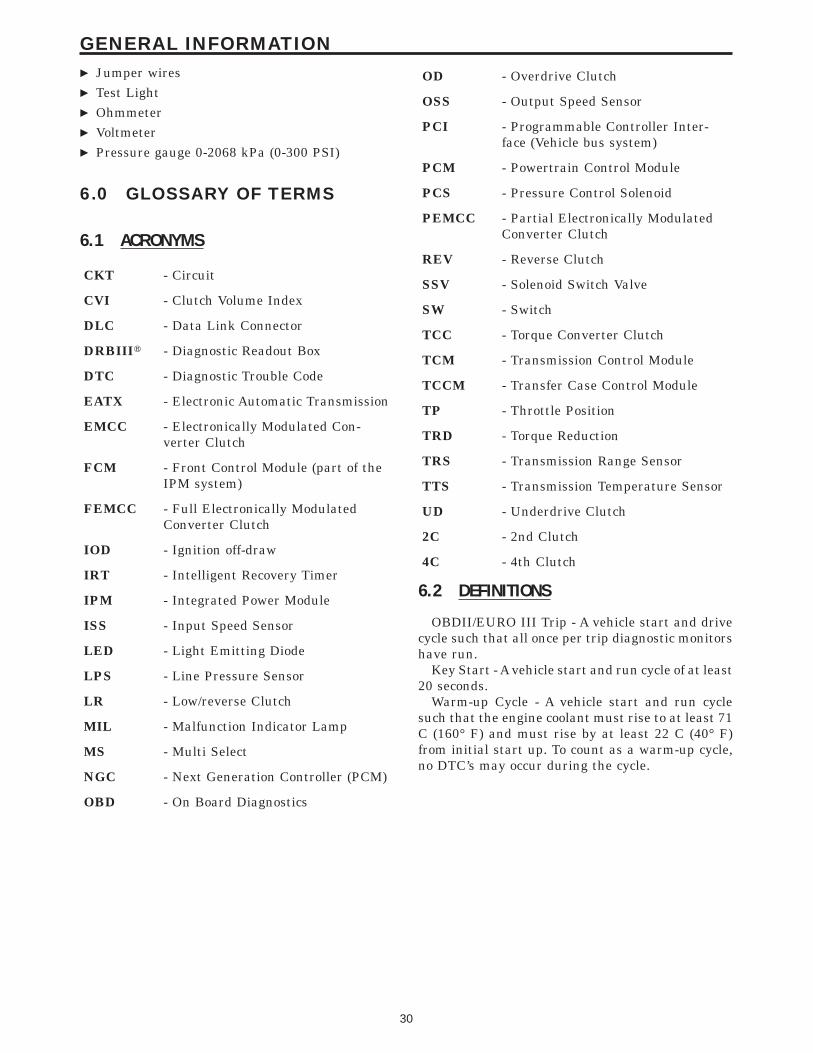
c Jumper wiresc Test Lightc Ohmmeterc Voltmeterc Pressure gauge 0-2068 kPa (0-300 PSI)
6.0 GLOSSARY OF TERMS
6.1 ACRONYMS
CKT - Circuit
CVI - Clutch Volume Index
DLC - Data Link Connector
DRBIIIt - Diagnostic Readout Box
DTC - Diagnostic Trouble Code
EATX - Electronic Automatic Transmission
EMCC - Electronically Modulated Con-verter Clutch
FCM - Front Control Module (part of theIPM system)
FEMCC - Full Electronically ModulatedConverter Clutch
IOD - Ignition off-draw
IRT - Intelligent Recovery Timer
IPM - Integrated Power Module
ISS - Input Speed Sensor
LED - Light Emitting Diode
LPS - Line Pressure Sensor
LR - Low/reverse Clutch
MIL - Malfunction Indicator Lamp
MS - Multi Select
NGC - Next Generation Controller (PCM)
OBD - On Board Diagnostics
OD - Overdrive Clutch
OSS - Output Speed Sensor
PCI - Programmable Controller Inter-face (Vehicle bus system)
PCM - Powertrain Control Module
PCS - Pressure Control Solenoid
PEMCC - Partial Electronically ModulatedConverter Clutch
REV - Reverse Clutch
SSV - Solenoid Switch Valve
SW - Switch
TCC - Torque Converter Clutch
TCM - Transmission Control Module
TCCM - Transfer Case Control Module
TP - Throttle Position
TRD - Torque Reduction
TRS - Transmission Range Sensor
TTS - Transmission Temperature Sensor
UD - Underdrive Clutch
2C - 2nd Clutch
4C - 4th Clutch
6.2 DEFINITIONS
OBDII/EURO III Trip - A vehicle start and drivecycle such that all once per trip diagnostic monitorshave run.
Key Start - A vehicle start and run cycle of at least20 seconds.
Warm-up Cycle - A vehicle start and run cyclesuch that the engine coolant must rise to at least 71C (160° F) and must rise by at least 22 C (40° F)from initial start up. To count as a warm-up cycle,no DTC’s may occur during the cycle.
30
GENERAL INFORMATION
7.0
DIAGNOSTIC INFORMATION ANDPROCEDURES
31
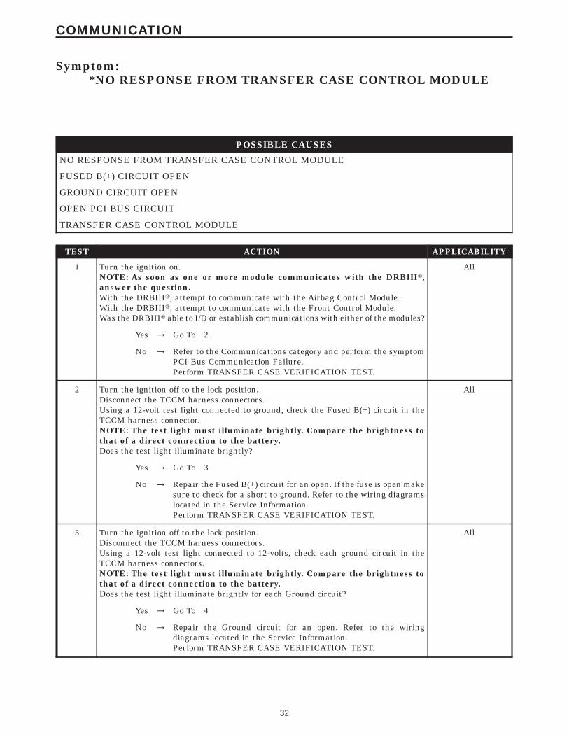
Symptom:*NO RESPONSE FROM TRANSFER CASE CONTROL MODULE
POSSIBLE CAUSES
NO RESPONSE FROM TRANSFER CASE CONTROL MODULE
FUSED B(+) CIRCUIT OPEN
GROUND CIRCUIT OPEN
OPEN PCI BUS CIRCUIT
TRANSFER CASE CONTROL MODULE
TEST ACTION APPLICABILITY
1 Turn the ignition on.NOTE: As soon as one or more module communicates with the DRBIIIt,answer the question.With the DRBIIIt, attempt to communicate with the Airbag Control Module.With the DRBIIIt, attempt to communicate with the Front Control Module.Was the DRBIIIt able to I/D or establish communications with either of the modules?
All
Yes → Go To 2
No → Refer to the Communications category and perform the symptomPCI Bus Communication Failure.Perform TRANSFER CASE VERIFICATION TEST.
2 Turn the ignition off to the lock position.Disconnect the TCCM harness connectors.Using a 12-volt test light connected to ground, check the Fused B(+) circuit in theTCCM harness connector.NOTE: The test light must illuminate brightly. Compare the brightness tothat of a direct connection to the battery.Does the test light illuminate brightly?
All
Yes → Go To 3
No → Repair the Fused B(+) circuit for an open. If the fuse is open makesure to check for a short to ground. Refer to the wiring diagramslocated in the Service Information.Perform TRANSFER CASE VERIFICATION TEST.
3 Turn the ignition off to the lock position.Disconnect the TCCM harness connectors.Using a 12-volt test light connected to 12-volts, check each ground circuit in theTCCM harness connectors.NOTE: The test light must illuminate brightly. Compare the brightness tothat of a direct connection to the battery.Does the test light illuminate brightly for each Ground circuit?
All
Yes → Go To 4
No → Repair the Ground circuit for an open. Refer to the wiringdiagrams located in the Service Information.Perform TRANSFER CASE VERIFICATION TEST.
32
COMMUNICATION
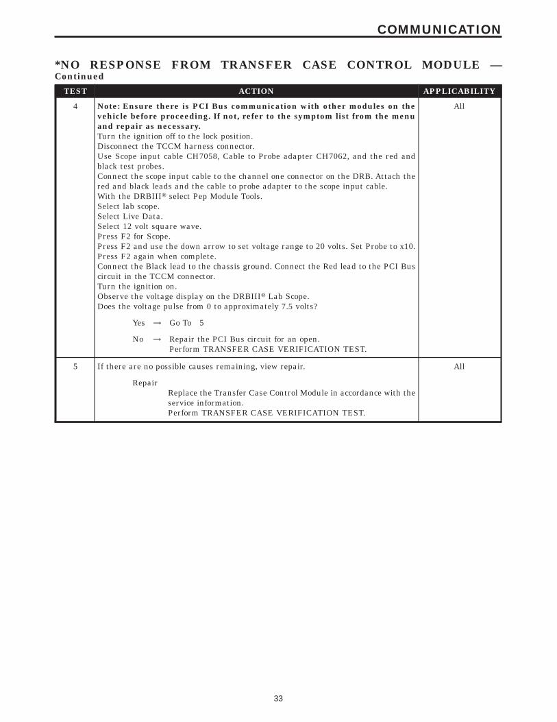
TEST ACTION APPLICABILITY
4 Note: Ensure there is PCI Bus communication with other modules on thevehicle before proceeding. If not, refer to the symptom list from the menuand repair as necessary.Turn the ignition off to the lock position.Disconnect the TCCM harness connector.Use Scope input cable CH7058, Cable to Probe adapter CH7062, and the red andblack test probes.Connect the scope input cable to the channel one connector on the DRB. Attach thered and black leads and the cable to probe adapter to the scope input cable.With the DRBIIIt select Pep Module Tools.Select lab scope.Select Live Data.Select 12 volt square wave.Press F2 for Scope.Press F2 and use the down arrow to set voltage range to 20 volts. Set Probe to x10.Press F2 again when complete.Connect the Black lead to the chassis ground. Connect the Red lead to the PCI Buscircuit in the TCCM connector.Turn the ignition on.Observe the voltage display on the DRBIIIt Lab Scope.Does the voltage pulse from 0 to approximately 7.5 volts?
All
Yes → Go To 5
No → Repair the PCI Bus circuit for an open.Perform TRANSFER CASE VERIFICATION TEST.
5 If there are no possible causes remaining, view repair. All
RepairReplace the Transfer Case Control Module in accordance with theservice information.Perform TRANSFER CASE VERIFICATION TEST.
33
COMMUNICATION
*NO RESPONSE FROM TRANSFER CASE CONTROL MODULE —Continued
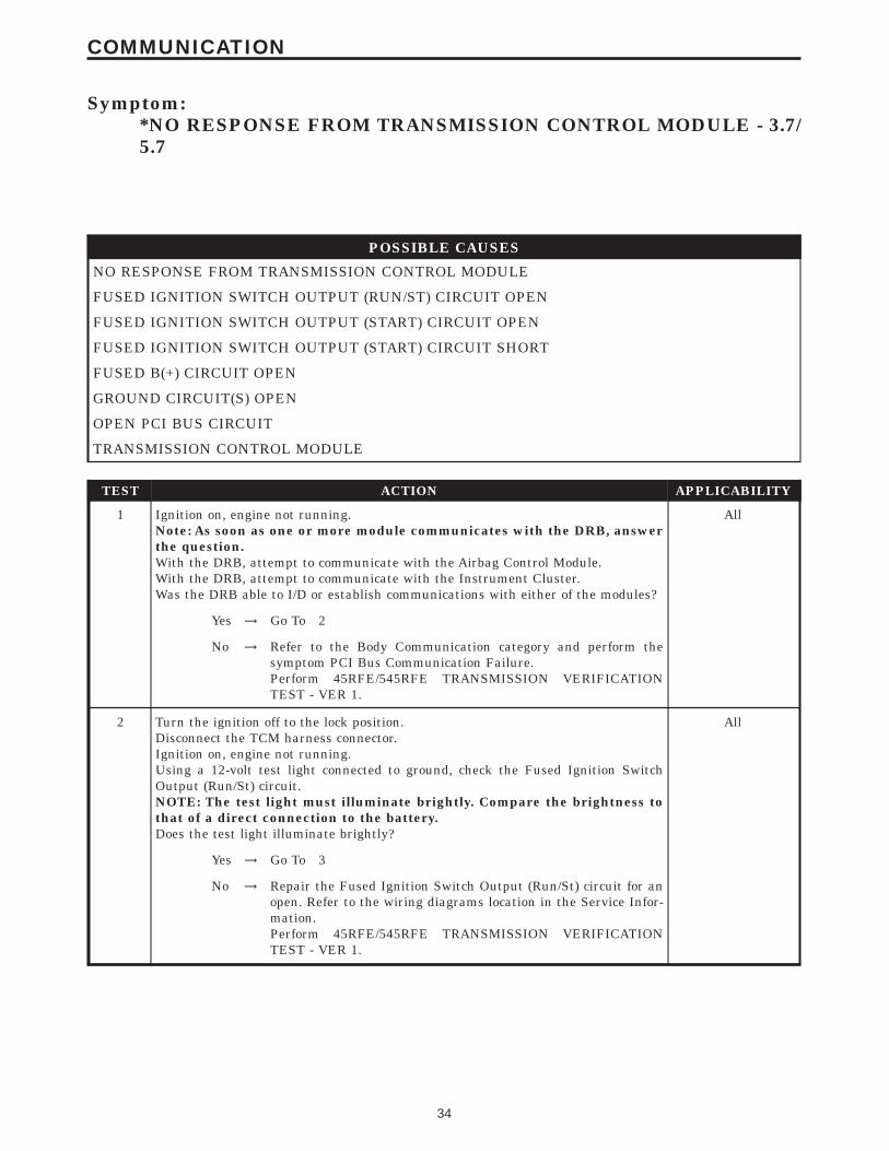
Symptom:*NO RESPONSE FROM TRANSMISSION CONTROL MODULE - 3.7/5.7
POSSIBLE CAUSES
NO RESPONSE FROM TRANSMISSION CONTROL MODULE
FUSED IGNITION SWITCH OUTPUT (RUN/ST) CIRCUIT OPEN
FUSED IGNITION SWITCH OUTPUT (START) CIRCUIT OPEN
FUSED IGNITION SWITCH OUTPUT (START) CIRCUIT SHORT
FUSED B(+) CIRCUIT OPEN
GROUND CIRCUIT(S) OPEN
OPEN PCI BUS CIRCUIT
TRANSMISSION CONTROL MODULE
TEST ACTION APPLICABILITY
1 Ignition on, engine not running.Note: As soon as one or more module communicates with the DRB, answerthe question.With the DRB, attempt to communicate with the Airbag Control Module.With the DRB, attempt to communicate with the Instrument Cluster.Was the DRB able to I/D or establish communications with either of the modules?
All
Yes → Go To 2
No → Refer to the Body Communication category and perform thesymptom PCI Bus Communication Failure.Perform 45RFE/545RFE TRANSMISSION VERIFICATIONTEST - VER 1.
2 Turn the ignition off to the lock position.Disconnect the TCM harness connector.Ignition on, engine not running.Using a 12-volt test light connected to ground, check the Fused Ignition SwitchOutput (Run/St) circuit.NOTE: The test light must illuminate brightly. Compare the brightness tothat of a direct connection to the battery.Does the test light illuminate brightly?
All
Yes → Go To 3
No → Repair the Fused Ignition Switch Output (Run/St) circuit for anopen. Refer to the wiring diagrams location in the Service Infor-mation.Perform 45RFE/545RFE TRANSMISSION VERIFICATIONTEST - VER 1.
34
COMMUNICATION
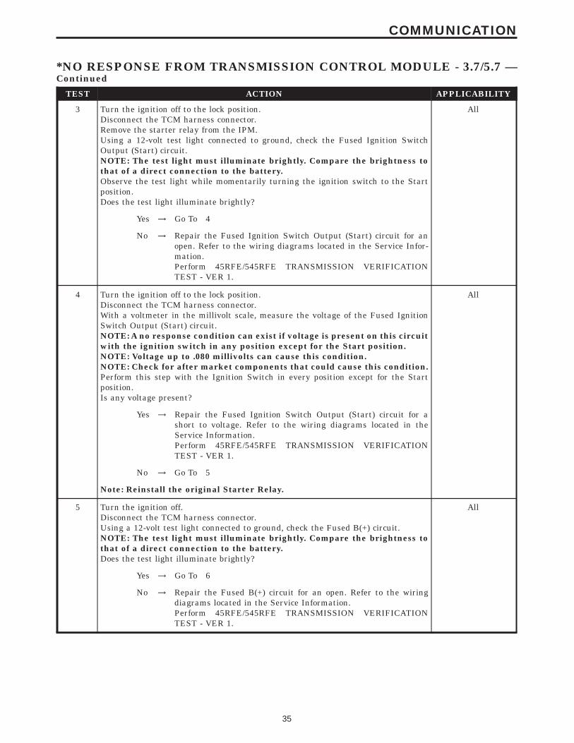
TEST ACTION APPLICABILITY
3 Turn the ignition off to the lock position.Disconnect the TCM harness connector.Remove the starter relay from the IPM.Using a 12-volt test light connected to ground, check the Fused Ignition SwitchOutput (Start) circuit.NOTE: The test light must illuminate brightly. Compare the brightness tothat of a direct connection to the battery.Observe the test light while momentarily turning the ignition switch to the Startposition.Does the test light illuminate brightly?
All
Yes → Go To 4
No → Repair the Fused Ignition Switch Output (Start) circuit for anopen. Refer to the wiring diagrams located in the Service Infor-mation.Perform 45RFE/545RFE TRANSMISSION VERIFICATIONTEST - VER 1.
4 Turn the ignition off to the lock position.Disconnect the TCM harness connector.With a voltmeter in the millivolt scale, measure the voltage of the Fused IgnitionSwitch Output (Start) circuit.NOTE: A no response condition can exist if voltage is present on this circuitwith the ignition switch in any position except for the Start position.NOTE: Voltage up to .080 millivolts can cause this condition.NOTE: Check for after market components that could cause this condition.Perform this step with the Ignition Switch in every position except for the Startposition.Is any voltage present?
All
Yes → Repair the Fused Ignition Switch Output (Start) circuit for ashort to voltage. Refer to the wiring diagrams located in theService Information.Perform 45RFE/545RFE TRANSMISSION VERIFICATIONTEST - VER 1.
No → Go To 5
Note: Reinstall the original Starter Relay.
5 Turn the ignition off.Disconnect the TCM harness connector.Using a 12-volt test light connected to ground, check the Fused B(+) circuit.NOTE: The test light must illuminate brightly. Compare the brightness tothat of a direct connection to the battery.Does the test light illuminate brightly?
All
Yes → Go To 6
No → Repair the Fused B(+) circuit for an open. Refer to the wiringdiagrams located in the Service Information.Perform 45RFE/545RFE TRANSMISSION VERIFICATIONTEST - VER 1.
35
COMMUNICATION
*NO RESPONSE FROM TRANSMISSION CONTROL MODULE - 3.7/5.7 —Continued
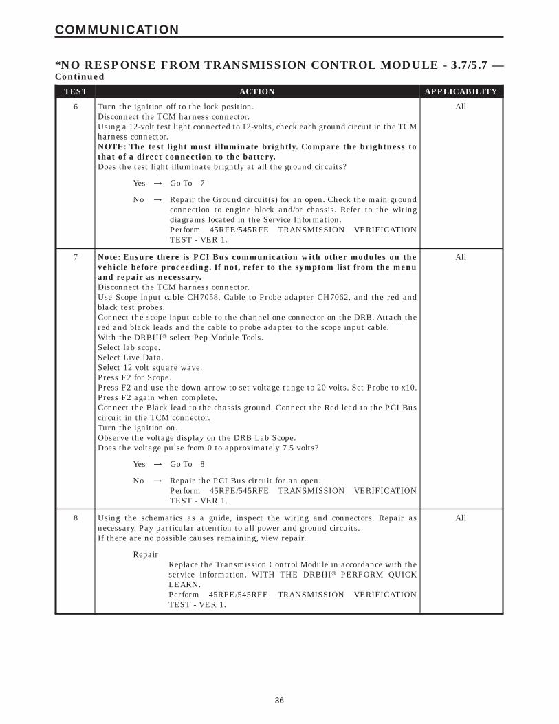
TEST ACTION APPLICABILITY
6 Turn the ignition off to the lock position.Disconnect the TCM harness connector.Using a 12-volt test light connected to 12-volts, check each ground circuit in the TCMharness connector.NOTE: The test light must illuminate brightly. Compare the brightness tothat of a direct connection to the battery.Does the test light illuminate brightly at all the ground circuits?
All
Yes → Go To 7
No → Repair the Ground circuit(s) for an open. Check the main groundconnection to engine block and/or chassis. Refer to the wiringdiagrams located in the Service Information.Perform 45RFE/545RFE TRANSMISSION VERIFICATIONTEST - VER 1.
7 Note: Ensure there is PCI Bus communication with other modules on thevehicle before proceeding. If not, refer to the symptom list from the menuand repair as necessary.Disconnect the TCM harness connector.Use Scope input cable CH7058, Cable to Probe adapter CH7062, and the red andblack test probes.Connect the scope input cable to the channel one connector on the DRB. Attach thered and black leads and the cable to probe adapter to the scope input cable.With the DRBIIIt select Pep Module Tools.Select lab scope.Select Live Data.Select 12 volt square wave.Press F2 for Scope.Press F2 and use the down arrow to set voltage range to 20 volts. Set Probe to x10.Press F2 again when complete.Connect the Black lead to the chassis ground. Connect the Red lead to the PCI Buscircuit in the TCM connector.Turn the ignition on.Observe the voltage display on the DRB Lab Scope.Does the voltage pulse from 0 to approximately 7.5 volts?
All
Yes → Go To 8
No → Repair the PCI Bus circuit for an open.Perform 45RFE/545RFE TRANSMISSION VERIFICATIONTEST - VER 1.
8 Using the schematics as a guide, inspect the wiring and connectors. Repair asnecessary. Pay particular attention to all power and ground circuits.If there are no possible causes remaining, view repair.
All
RepairReplace the Transmission Control Module in accordance with theservice information. WITH THE DRBIIIt PERFORM QUICKLEARN.Perform 45RFE/545RFE TRANSMISSION VERIFICATIONTEST - VER 1.
36
COMMUNICATION
*NO RESPONSE FROM TRANSMISSION CONTROL MODULE - 3.7/5.7 —Continued
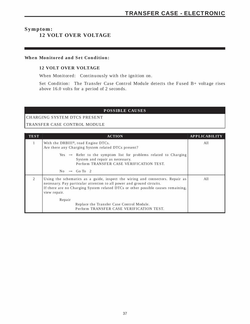
Symptom:12 VOLT OVER VOLTAGE
When Monitored and Set Condition:
12 VOLT OVER VOLTAGE
When Monitored: Continuously with the ignition on.
Set Condition: The Transfer Case Control Module detects the Fused B+ voltage risesabove 16.0 volts for a period of 2 seconds.
POSSIBLE CAUSES
CHARGING SYSTEM DTCS PRESENT
TRANSFER CASE CONTROL MODULE
TEST ACTION APPLICABILITY
1 With the DRBIIIt, read Engine DTCs.Are there any Charging System related DTCs present?
All
Yes → Refer to the symptom list for problems related to ChargingSystem and repair as necessary.Perform TRANSFER CASE VERIFICATION TEST.
No → Go To 2
2 Using the schematics as a guide, inspect the wiring and connectors. Repair asnecessary. Pay particular attention to all power and ground circuits.If there are no Charging System related DTCs or other possible causes remaining,view repair.
All
RepairReplace the Transfer Case Control Module.Perform TRANSFER CASE VERIFICATION TEST.
37
TRANSFER CASE - ELECTRONIC
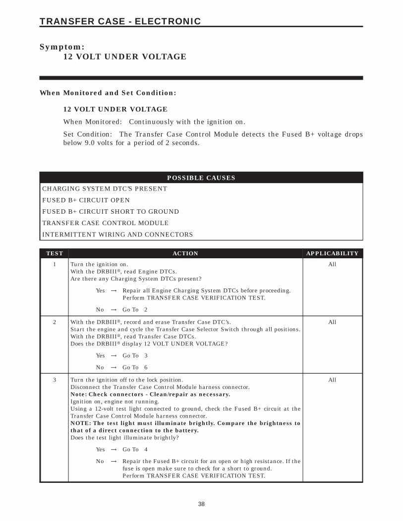
Symptom:12 VOLT UNDER VOLTAGE
When Monitored and Set Condition:
12 VOLT UNDER VOLTAGE
When Monitored: Continuously with the ignition on.
Set Condition: The Transfer Case Control Module detects the Fused B+ voltage dropsbelow 9.0 volts for a period of 2 seconds.
POSSIBLE CAUSES
CHARGING SYSTEM DTC’S PRESENT
FUSED B+ CIRCUIT OPEN
FUSED B+ CIRCUIT SHORT TO GROUND
TRANSFER CASE CONTROL MODULE
INTERMITTENT WIRING AND CONNECTORS
TEST ACTION APPLICABILITY
1 Turn the ignition on.With the DRBIIIt, read Engine DTCs.Are there any Charging System DTCs present?
All
Yes → Repair all Engine Charging System DTCs before proceeding.Perform TRANSFER CASE VERIFICATION TEST.
No → Go To 2
2 With the DRBIIIt, record and erase Transfer Case DTC’s.Start the engine and cycle the Transfer Case Selector Switch through all positions.With the DRBIIIt, read Transfer Case DTCs.Does the DRBIIIt display 12 VOLT UNDER VOLTAGE?
All
Yes → Go To 3
No → Go To 6
3 Turn the ignition off to the lock position.Disconnect the Transfer Case Control Module harness connector.Note: Check connectors - Clean/repair as necessary.Ignition on, engine not running.Using a 12-volt test light connected to ground, check the Fused B+ circuit at theTransfer Case Control Module harness connector.NOTE: The test light must illuminate brightly. Compare the brightness tothat of a direct connection to the battery.Does the test light illuminate brightly?
All
Yes → Go To 4
No → Repair the Fused B+ circuit for an open or high resistance. If thefuse is open make sure to check for a short to ground.Perform TRANSFER CASE VERIFICATION TEST.
38
TRANSFER CASE - ELECTRONIC
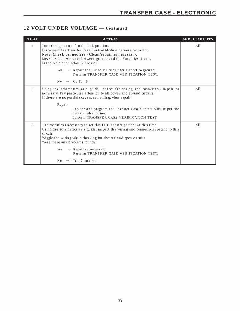
TEST ACTION APPLICABILITY
4 Turn the ignition off to the lock position.Disconnect the Transfer Case Control Module harness connector.Note: Check connectors - Clean/repair as necessary.Measure the resistance between ground and the Fused B+ circuit.Is the resistance below 5.0 ohms?
All
Yes → Repair the Fused B+ circuit for a short to ground.Perform TRANSFER CASE VERIFICATION TEST.
No → Go To 5
5 Using the schematics as a guide, inspect the wiring and connectors. Repair asnecessary. Pay particular attention to all power and ground circuits.If there are no possible causes remaining, view repair.
All
RepairReplace and program the Transfer Case Control Module per theService Information.Perform TRANSFER CASE VERIFICATION TEST.
6 The conditions necessary to set this DTC are not present at this time.Using the schematics as a guide, inspect the wiring and connectors specific to thiscircuit.Wiggle the wiring while checking for shorted and open circuits.Were there any problems found?
All
Yes → Repair as necessary.Perform TRANSFER CASE VERIFICATION TEST.
No → Test Complete.
39
TRANSFER CASE - ELECTRONIC
12 VOLT UNDER VOLTAGE — Continued
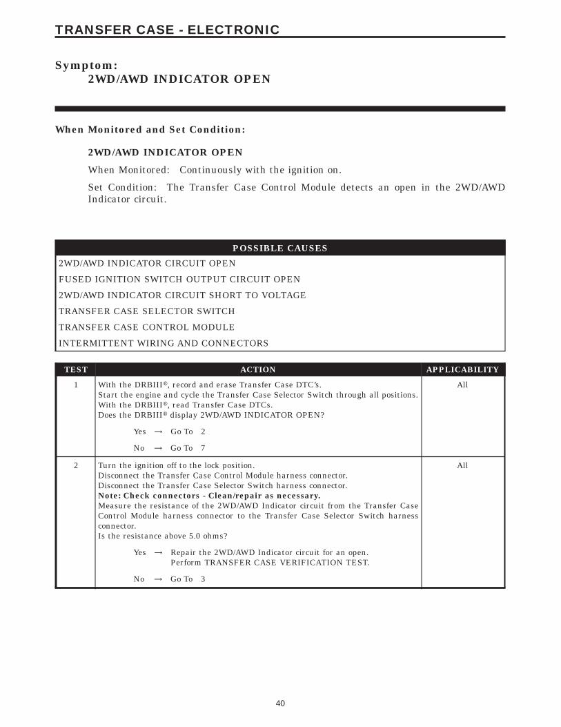
Symptom:2WD/AWD INDICATOR OPEN
When Monitored and Set Condition:
2WD/AWD INDICATOR OPEN
When Monitored: Continuously with the ignition on.
Set Condition: The Transfer Case Control Module detects an open in the 2WD/AWDIndicator circuit.
POSSIBLE CAUSES
2WD/AWD INDICATOR CIRCUIT OPEN
FUSED IGNITION SWITCH OUTPUT CIRCUIT OPEN
2WD/AWD INDICATOR CIRCUIT SHORT TO VOLTAGE
TRANSFER CASE SELECTOR SWITCH
TRANSFER CASE CONTROL MODULE
INTERMITTENT WIRING AND CONNECTORS
TEST ACTION APPLICABILITY
1 With the DRBIIIt, record and erase Transfer Case DTC’s.Start the engine and cycle the Transfer Case Selector Switch through all positions.With the DRBIIIt, read Transfer Case DTCs.Does the DRBIIIt display 2WD/AWD INDICATOR OPEN?
All
Yes → Go To 2
No → Go To 7
2 Turn the ignition off to the lock position.Disconnect the Transfer Case Control Module harness connector.Disconnect the Transfer Case Selector Switch harness connector.Note: Check connectors - Clean/repair as necessary.Measure the resistance of the 2WD/AWD Indicator circuit from the Transfer CaseControl Module harness connector to the Transfer Case Selector Switch harnessconnector.Is the resistance above 5.0 ohms?
All
Yes → Repair the 2WD/AWD Indicator circuit for an open.Perform TRANSFER CASE VERIFICATION TEST.
No → Go To 3
40
TRANSFER CASE - ELECTRONIC
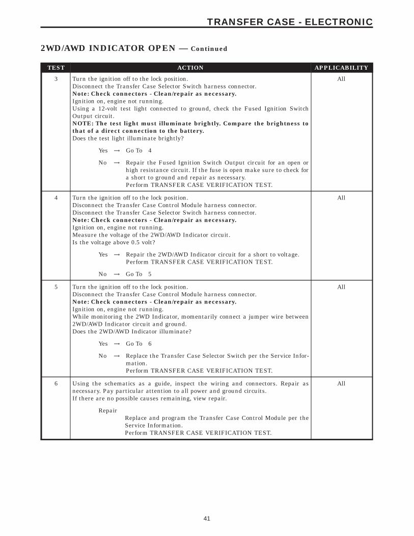
TEST ACTION APPLICABILITY
3 Turn the ignition off to the lock position.Disconnect the Transfer Case Selector Switch harness connector.Note: Check connectors - Clean/repair as necessary.Ignition on, engine not running.Using a 12-volt test light connected to ground, check the Fused Ignition SwitchOutput circuit.NOTE: The test light must illuminate brightly. Compare the brightness tothat of a direct connection to the battery.Does the test light illuminate brightly?
All
Yes → Go To 4
No → Repair the Fused Ignition Switch Output circuit for an open orhigh resistance circuit. If the fuse is open make sure to check fora short to ground and repair as necessary.Perform TRANSFER CASE VERIFICATION TEST.
4 Turn the ignition off to the lock position.Disconnect the Transfer Case Control Module harness connector.Disconnect the Transfer Case Selector Switch harness connector.Note: Check connectors - Clean/repair as necessary.Ignition on, engine not running.Measure the voltage of the 2WD/AWD Indicator circuit.Is the voltage above 0.5 volt?
All
Yes → Repair the 2WD/AWD Indicator circuit for a short to voltage.Perform TRANSFER CASE VERIFICATION TEST.
No → Go To 5
5 Turn the ignition off to the lock position.Disconnect the Transfer Case Control Module harness connector.Note: Check connectors - Clean/repair as necessary.Ignition on, engine not running.While monitoring the 2WD Indicator, momentarily connect a jumper wire between2WD/AWD Indicator circuit and ground.Does the 2WD/AWD Indicator illuminate?
All
Yes → Go To 6
No → Replace the Transfer Case Selector Switch per the Service Infor-mation.Perform TRANSFER CASE VERIFICATION TEST.
6 Using the schematics as a guide, inspect the wiring and connectors. Repair asnecessary. Pay particular attention to all power and ground circuits.If there are no possible causes remaining, view repair.
All
RepairReplace and program the Transfer Case Control Module per theService Information.Perform TRANSFER CASE VERIFICATION TEST.
41
TRANSFER CASE - ELECTRONIC
2WD/AWD INDICATOR OPEN — Continued
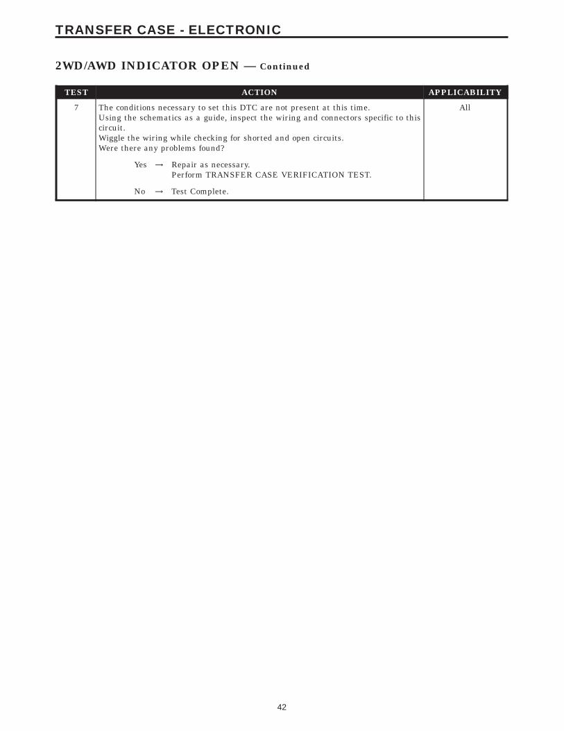
TEST ACTION APPLICABILITY
7 The conditions necessary to set this DTC are not present at this time.Using the schematics as a guide, inspect the wiring and connectors specific to thiscircuit.Wiggle the wiring while checking for shorted and open circuits.Were there any problems found?
All
Yes → Repair as necessary.Perform TRANSFER CASE VERIFICATION TEST.
No → Test Complete.
42
TRANSFER CASE - ELECTRONIC
2WD/AWD INDICATOR OPEN — Continued
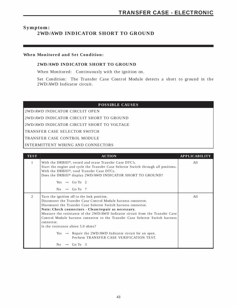
Symptom:2WD/AWD INDICATOR SHORT TO GROUND
When Monitored and Set Condition:
2WD/AWD INDICATOR SHORT TO GROUND
When Monitored: Continuously with the ignition on.
Set Condition: The Transfer Case Control Module detects a short to ground in the2WD/AWD Indicator circuit.
POSSIBLE CAUSES
2WD/AWD INDICATOR CIRCUIT OPEN
2WD/AWD INDICATOR CIRCUIT SHORT TO GROUND
2WD/AWD INDICATOR CIRCUIT SHORT TO VOLTAGE
TRANSFER CASE SELECTOR SWITCH
TRANSFER CASE CONTROL MODULE
INTERMITTENT WIRING AND CONNECTORS
TEST ACTION APPLICABILITY
1 With the DRBIIIt, record and erase Transfer Case DTC’s.Start the engine and cycle the Transfer Case Selector Switch through all positions.With the DRBIIIt, read Transfer Case DTCs.Does the DRBIIIt display 2WD/AWD INDICATOR SHORT TO GROUND?
All
Yes → Go To 2
No → Go To 7
2 Turn the ignition off to the lock position.Disconnect the Transfer Case Control Module harness connector.Disconnect the Transfer Case Selector Switch harness connector.Note: Check connectors - Clean/repair as necessary.Measure the resistance of the 2WD/AWD Indicator circuit from the Transfer CaseControl Module harness connector to the Transfer Case Selector Switch harnessconnector.Is the resistance above 5.0 ohms?
All
Yes → Repair the 2WD/AWD Indicator circuit for an open.Perform TRANSFER CASE VERIFICATION TEST.
No → Go To 3
43
TRANSFER CASE - ELECTRONIC
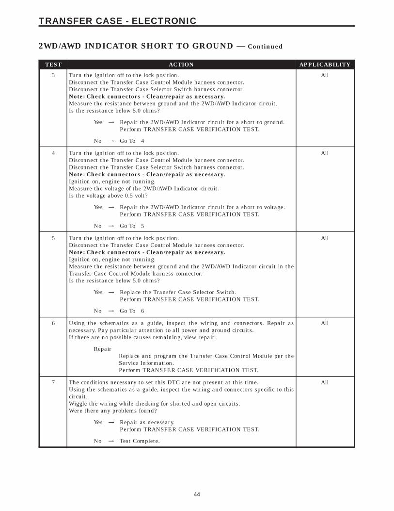
TEST ACTION APPLICABILITY
3 Turn the ignition off to the lock position.Disconnect the Transfer Case Control Module harness connector.Disconnect the Transfer Case Selector Switch harness connector.Note: Check connectors - Clean/repair as necessary.Measure the resistance between ground and the 2WD/AWD Indicator circuit.Is the resistance below 5.0 ohms?
All
Yes → Repair the 2WD/AWD Indicator circuit for a short to ground.Perform TRANSFER CASE VERIFICATION TEST.
No → Go To 4
4 Turn the ignition off to the lock position.Disconnect the Transfer Case Control Module harness connector.Disconnect the Transfer Case Selector Switch harness connector.Note: Check connectors - Clean/repair as necessary.Ignition on, engine not running.Measure the voltage of the 2WD/AWD Indicator circuit.Is the voltage above 0.5 volt?
All
Yes → Repair the 2WD/AWD Indicator circuit for a short to voltage.Perform TRANSFER CASE VERIFICATION TEST.
No → Go To 5
5 Turn the ignition off to the lock position.Disconnect the Transfer Case Control Module harness connector.Note: Check connectors - Clean/repair as necessary.Ignition on, engine not running.Measure the resistance between ground and the 2WD/AWD Indicator circuit in theTransfer Case Control Module harness connector.Is the resistance below 5.0 ohms?
All
Yes → Replace the Transfer Case Selector Switch.Perform TRANSFER CASE VERIFICATION TEST.
No → Go To 6
6 Using the schematics as a guide, inspect the wiring and connectors. Repair asnecessary. Pay particular attention to all power and ground circuits.If there are no possible causes remaining, view repair.
All
RepairReplace and program the Transfer Case Control Module per theService Information.Perform TRANSFER CASE VERIFICATION TEST.
7 The conditions necessary to set this DTC are not present at this time.Using the schematics as a guide, inspect the wiring and connectors specific to thiscircuit.Wiggle the wiring while checking for shorted and open circuits.Were there any problems found?
All
Yes → Repair as necessary.Perform TRANSFER CASE VERIFICATION TEST.
No → Test Complete.
44
TRANSFER CASE - ELECTRONIC
2WD/AWD INDICATOR SHORT TO GROUND — Continued
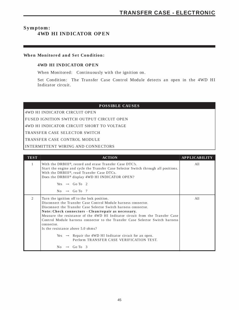
Symptom:4WD HI INDICATOR OPEN
When Monitored and Set Condition:
4WD HI INDICATOR OPEN
When Monitored: Continuously with the ignition on.
Set Condition: The Transfer Case Control Module detects an open in the 4WD HIIndicator circuit.
POSSIBLE CAUSES
4WD HI INDICATOR CIRCUIT OPEN
FUSED IGNITION SWITCH OUTPUT CIRCUIT OPEN
4WD HI INDICATOR CIRCUIT SHORT TO VOLTAGE
TRANSFER CASE SELECTOR SWITCH
TRANSFER CASE CONTROL MODULE
INTERMITTENT WIRING AND CONNECTORS
TEST ACTION APPLICABILITY
1 With the DRBIIIt, record and erase Transfer Case DTC’s.Start the engine and cycle the Transfer Case Selector Switch through all positions.With the DRBIIIt, read Transfer Case DTCs.Does the DRBIIIt display 4WD HI INDICATOR OPEN?
All
Yes → Go To 2
No → Go To 7
2 Turn the ignition off to the lock position.Disconnect the Transfer Case Control Module harness connector.Disconnect the Transfer Case Selector Switch harness connector.Note: Check connectors - Clean/repair as necessary.Measure the resistance of the 4WD HI Indicator circuit from the Transfer CaseControl Module harness connector to the Transfer Case Selector Switch harnessconnector.Is the resistance above 5.0 ohms?
All
Yes → Repair the 4WD HI Indicator circuit for an open.Perform TRANSFER CASE VERIFICATION TEST.
No → Go To 3
45
TRANSFER CASE - ELECTRONIC

TEST ACTION APPLICABILITY
3 Turn the ignition off to the lock position.Disconnect the Transfer Case Selector Switch harness connector.Note: Check connectors - Clean/repair as necessary.Ignition on, engine not running.Using a 12-volt test light connected to ground, check the Fused Ignition SwitchOutput circuit.NOTE: The test light must illuminate brightly. Compare the brightness tothat of a direct connection to the battery.Does the test light illuminate brightly?
All
Yes → Go To 4
No → Repair the Fused Ignition Switch Output circuit for an open orhigh resistance circuit. If the fuse is open make sure to check fora short to ground and repair as necessary.Perform TRANSFER CASE VERIFICATION TEST.
4 Turn the ignition off to the lock position.Disconnect the Transfer Case Control Module harness connector.Disconnect the Transfer Case Selector Switch harness connector.Note: Check connectors - Clean/repair as necessary.Ignition on, engine not running.Measure the voltage of the 4WD HI Indicator circuit.Is the voltage above 0.5 volt?
All
Yes → Repair the 4WD HI Indicator circuit for a short to voltage.Perform TRANSFER CASE VERIFICATION TEST.
No → Go To 5
5 Turn the ignition off to the lock position.Disconnect the Transfer Case Control Module harness connector.Note: Check connectors - Clean/repair as necessary.Ignition on, engine not running.While monitoring the 4WD HI Indicator, momentarily connect a jumper wirebetween 4WD HI Indicator circuit and ground.Does the 4WD HI LED illuminate?
All
Yes → Go To 6
No → Replace the Transfer Case Selector Switch.Perform TRANSFER CASE VERIFICATION TEST.
6 Using the schematics as a guide, inspect the wiring and connectors. Repair asnecessary. Pay particular attention to all power and ground circuits.If there are no possible causes remaining, view repair.
All
RepairReplace and program the Transfer Case Control Module per theService Information.Perform TRANSFER CASE VERIFICATION TEST.
7 The conditions necessary to set this DTC are not present at this time.Using the schematics as a guide, inspect the wiring and connectors specific to thiscircuit.Wiggle the wiring while checking for shorted and open circuits.Were there any problems found?
All
Yes → Repair as necessary.Perform TRANSFER CASE VERIFICATION TEST.
No → Test Complete.
46
TRANSFER CASE - ELECTRONIC
4WD HI INDICATOR OPEN — Continued

Symptom:4WD HI INDICATOR SHORT TO GROUND
When Monitored and Set Condition:
4WD HI INDICATOR SHORT TO GROUND
When Monitored: Continuously with the ignition on.
Set Condition: The Transfer Case Control Module detects a short to ground in the 4WDHI Indicator circuit.
POSSIBLE CAUSES
INTERMITTENT WIRING AND CONNECTORS
4WD HI INDICATOR CIRCUIT OPEN
4WD HI INDICATOR CIRCUIT SHORT TO GROUND
4WD HI INDICATOR CIRCUIT SHORT TO VOLTAGE
TRANSFER CASE SELECTOR SWITCH
TRANSFER CASE CONTROL MODULE
TEST ACTION APPLICABILITY
1 With the DRBIIIt, record and erase Transfer Case DTC’s.Start the engine and cycle the Transfer Case Selector Switch through all positions.With the DRBIIIt, read Transfer Case DTCs.Does the DRBIIIt display 4WD HI INDICATOR SHORT TO GROUND?
All
Yes → Go To 2
No → Go To 7
2 Turn the ignition off to the lock position.Disconnect the Transfer Case Control Module harness connector.Disconnect the Transfer Case Selector Switch harness connector.Note: Check connectors - Clean/repair as necessary.Measure the resistance of the 4WD HI Indicator circuit from the Transfer CaseControl Module harness connector to the Transfer Case Selector Switch harnessconnector.Is the resistance above 5.0 ohms?
All
Yes → Repair the 4WD HI Indicator circuit for an open.Perform TRANSFER CASE VERIFICATION TEST.
No → Go To 3
47
TRANSFER CASE - ELECTRONIC

TEST ACTION APPLICABILITY
3 Turn the ignition off to the lock position.Disconnect the Transfer Case Control Module harness connector.Disconnect the Transfer Case Selector Switch harness connector.Note: Check connectors - Clean/repair as necessary.Measure the resistance between ground and the 4WD HI Indicator circuit.Is the resistance below 5.0 ohms?
All
Yes → Repair the 4WD HI Indicator circuit for a short to ground.Perform TRANSFER CASE VERIFICATION TEST.
No → Go To 4
4 Turn the ignition off to the lock position.Disconnect the Transfer Case Control Module harness connector.Disconnect the Transfer Case Selector Switch harness connector.Note: Check connectors - Clean/repair as necessary.Ignition on, engine not running.Measure the voltage of the 4WD HI Indicator circuit.Is the voltage above 0.5 volt?
All
Yes → Repair the 4WD HI Indicator circuit for a short to voltage.Perform TRANSFER CASE VERIFICATION TEST.
No → Go To 5
5 Turn the ignition off to the lock position.Disconnect the Transfer Case Control Module harness connector.Note: Check connectors - Clean/repair as necessary.Ignition on, engine not running.Measure the resistance between ground and the 4WD HI Indicator circuit.Is the resistance below 5.0 ohms?
All
Yes → Replace the Transfer Case Selector Switch.Perform TRANSFER CASE VERIFICATION TEST.
No → Go To 6
6 Using the schematics as a guide, inspect the wiring and connectors. Repair asnecessary. Pay particular attention to all power and ground circuits.If there are no possible causes remaining, view repair.
All
RepairReplace and program the Transfer Case Control Module per theService Information.Perform TRANSFER CASE VERIFICATION TEST.
7 The conditions necessary to set this DTC are not present at this time.Using the schematics as a guide, inspect the wiring and connectors specific to thiscircuit.Wiggle the wiring while checking for shorts and open circuits.Were there any problems found?
All
Yes → Repair as necessary.Perform TRANSFER CASE VERIFICATION TEST.
No → Test Complete.
48
TRANSFER CASE - ELECTRONIC
4WD HI INDICATOR SHORT TO GROUND — Continued

Symptom:4WD LO INDICATOR OPEN
When Monitored and Set Condition:
4WD LO INDICATOR OPEN
When Monitored: Continuously with the ignition on.
Set Condition: The Transfer Case Control Module detects an open in the 4WD LOIndicator circuit.
POSSIBLE CAUSES
4WD LO INDICATOR CIRCUIT OPEN
FUSED IGNITION SWITCH OUTPUT CIRCUIT OPEN
4WD LO INDICATOR CIRCUIT SHORT TO VOLTAGE
TRANSFER CASE SELECTOR SWITCH
TRANSFER CASE CONTROL MODULE
INTERMITTENT WIRING AND CONNECTORS
TEST ACTION APPLICABILITY
1 With the DRBIIIt, record and erase Transfer Case DTC’s.Start the engine and cycle the Transfer Case Selector Switch through all positions.With the DRBIIIt, read Transfer Case DTCs.Does the DRBIIIt display 4WD LO INDICATOR OPEN?
All
Yes → Go To 2
No → Go To 7
2 Turn the ignition off to the lock position.Disconnect the Transfer Case Control Module harness connector.Disconnect the Transfer Case Selector Switch harness connector.Note: Check connectors - Clean/repair as necessary.Measure the resistance of the 4WD LO Indicator circuit from the Transfer CaseControl Module harness connector to the Transfer Case Selector Switch harnessconnector.Is the resistance above 5.0 ohms?
All
Yes → Repair the 4WD LO Indicator circuit for an open.Perform TRANSFER CASE VERIFICATION TEST.
No → Go To 3
49
TRANSFER CASE - ELECTRONIC
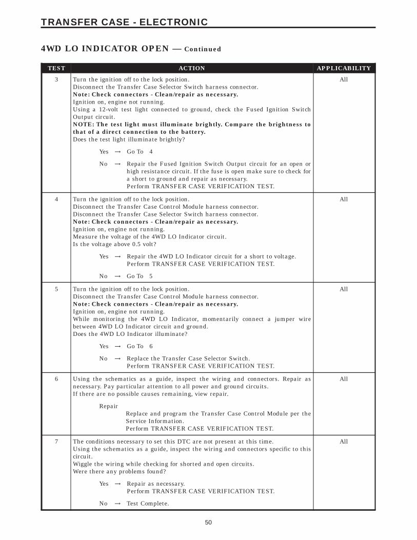
TEST ACTION APPLICABILITY
3 Turn the ignition off to the lock position.Disconnect the Transfer Case Selector Switch harness connector.Note: Check connectors - Clean/repair as necessary.Ignition on, engine not running.Using a 12-volt test light connected to ground, check the Fused Ignition SwitchOutput circuit.NOTE: The test light must illuminate brightly. Compare the brightness tothat of a direct connection to the battery.Does the test light illuminate brightly?
All
Yes → Go To 4
No → Repair the Fused Ignition Switch Output circuit for an open orhigh resistance circuit. If the fuse is open make sure to check fora short to ground and repair as necessary.Perform TRANSFER CASE VERIFICATION TEST.
4 Turn the ignition off to the lock position.Disconnect the Transfer Case Control Module harness connector.Disconnect the Transfer Case Selector Switch harness connector.Note: Check connectors - Clean/repair as necessary.Ignition on, engine not running.Measure the voltage of the 4WD LO Indicator circuit.Is the voltage above 0.5 volt?
All
Yes → Repair the 4WD LO Indicator circuit for a short to voltage.Perform TRANSFER CASE VERIFICATION TEST.
No → Go To 5
5 Turn the ignition off to the lock position.Disconnect the Transfer Case Control Module harness connector.Note: Check connectors - Clean/repair as necessary.Ignition on, engine not running.While monitoring the 4WD LO Indicator, momentarily connect a jumper wirebetween 4WD LO Indicator circuit and ground.Does the 4WD LO Indicator illuminate?
All
Yes → Go To 6
No → Replace the Transfer Case Selector Switch.Perform TRANSFER CASE VERIFICATION TEST.
6 Using the schematics as a guide, inspect the wiring and connectors. Repair asnecessary. Pay particular attention to all power and ground circuits.If there are no possible causes remaining, view repair.
All
RepairReplace and program the Transfer Case Control Module per theService Information.Perform TRANSFER CASE VERIFICATION TEST.
7 The conditions necessary to set this DTC are not present at this time.Using the schematics as a guide, inspect the wiring and connectors specific to thiscircuit.Wiggle the wiring while checking for shorted and open circuits.Were there any problems found?
All
Yes → Repair as necessary.Perform TRANSFER CASE VERIFICATION TEST.
No → Test Complete.
50
TRANSFER CASE - ELECTRONIC
4WD LO INDICATOR OPEN — Continued
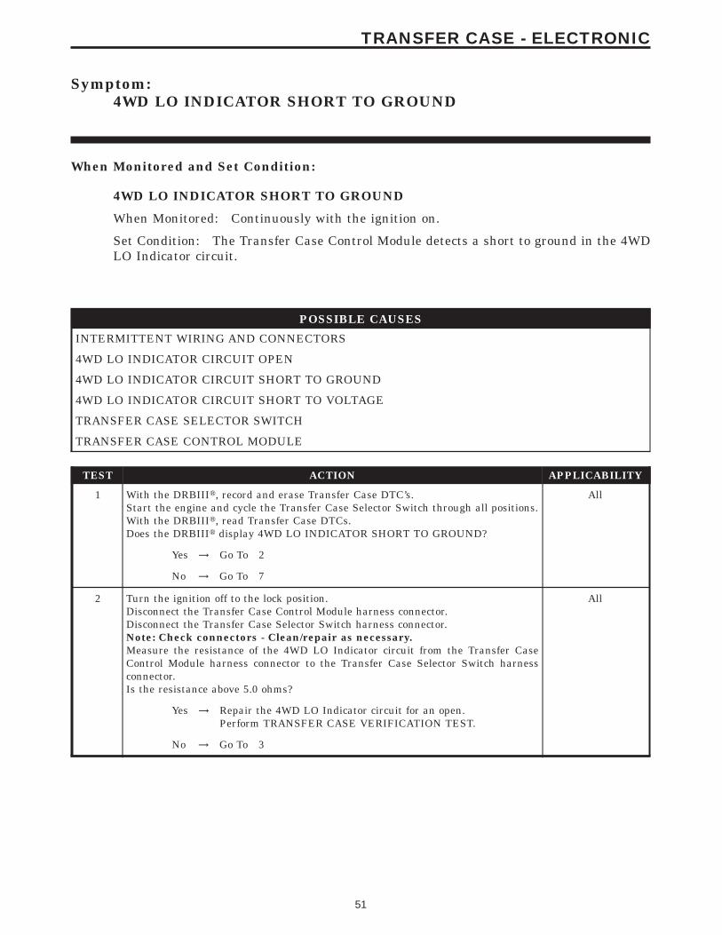
Symptom:4WD LO INDICATOR SHORT TO GROUND
When Monitored and Set Condition:
4WD LO INDICATOR SHORT TO GROUND
When Monitored: Continuously with the ignition on.
Set Condition: The Transfer Case Control Module detects a short to ground in the 4WDLO Indicator circuit.
POSSIBLE CAUSES
INTERMITTENT WIRING AND CONNECTORS
4WD LO INDICATOR CIRCUIT OPEN
4WD LO INDICATOR CIRCUIT SHORT TO GROUND
4WD LO INDICATOR CIRCUIT SHORT TO VOLTAGE
TRANSFER CASE SELECTOR SWITCH
TRANSFER CASE CONTROL MODULE
TEST ACTION APPLICABILITY
1 With the DRBIIIt, record and erase Transfer Case DTC’s.Start the engine and cycle the Transfer Case Selector Switch through all positions.With the DRBIIIt, read Transfer Case DTCs.Does the DRBIIIt display 4WD LO INDICATOR SHORT TO GROUND?
All
Yes → Go To 2
No → Go To 7
2 Turn the ignition off to the lock position.Disconnect the Transfer Case Control Module harness connector.Disconnect the Transfer Case Selector Switch harness connector.Note: Check connectors - Clean/repair as necessary.Measure the resistance of the 4WD LO Indicator circuit from the Transfer CaseControl Module harness connector to the Transfer Case Selector Switch harnessconnector.Is the resistance above 5.0 ohms?
All
Yes → Repair the 4WD LO Indicator circuit for an open.Perform TRANSFER CASE VERIFICATION TEST.
No → Go To 3
51
TRANSFER CASE - ELECTRONIC
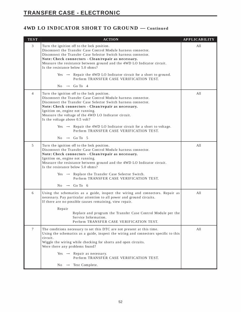
TEST ACTION APPLICABILITY
3 Turn the ignition off to the lock position.Disconnect the Transfer Case Control Module harness connector.Disconnect the Transfer Case Selector Switch harness connector.Note: Check connectors - Clean/repair as necessary.Measure the resistance between ground and the 4WD LO Indicator circuit.Is the resistance below 5.0 ohms?
All
Yes → Repair the 4WD LO Indicator circuit for a short to ground.Perform TRANSFER CASE VERIFICATION TEST.
No → Go To 4
4 Turn the ignition off to the lock position.Disconnect the Transfer Case Control Module harness connector.Disconnect the Transfer Case Selector Switch harness connector.Note: Check connectors - Clean/repair as necessary.Ignition on, engine not running.Measure the voltage of the 4WD LO Indicator circuit.Is the voltage above 0.5 volt?
All
Yes → Repair the 4WD LO Indicator circuit for a short to voltage.Perform TRANSFER CASE VERIFICATION TEST.
No → Go To 5
5 Turn the ignition off to the lock position.Disconnect the Transfer Case Control Module harness connector.Note: Check connectors - Clean/repair as necessary.Ignition on, engine not running.Measure the resistance between ground and the 4WD LO Indicator circuit.Is the resistance below 5.0 ohms?
All
Yes → Replace the Transfer Case Selector Switch.Perform TRANSFER CASE VERIFICATION TEST.
No → Go To 6
6 Using the schematics as a guide, inspect the wiring and connectors. Repair asnecessary. Pay particular attention to all power and ground circuits.If there are no possible causes remaining, view repair.
All
RepairReplace and program the Transfer Case Control Module per theService Information.Perform TRANSFER CASE VERIFICATION TEST.
7 The conditions necessary to set this DTC are not present at this time.Using the schematics as a guide, inspect the wiring and connectors specific to thiscircuit.Wiggle the wiring while checking for shorts and open circuits.Were there any problems found?
All
Yes → Repair as necessary.Perform TRANSFER CASE VERIFICATION TEST.
No → Test Complete.
52
TRANSFER CASE - ELECTRONIC
4WD LO INDICATOR SHORT TO GROUND — Continued
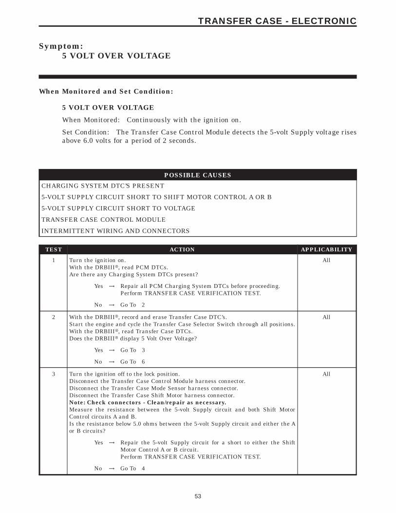
Symptom:5 VOLT OVER VOLTAGE
When Monitored and Set Condition:
5 VOLT OVER VOLTAGE
When Monitored: Continuously with the ignition on.
Set Condition: The Transfer Case Control Module detects the 5-volt Supply voltage risesabove 6.0 volts for a period of 2 seconds.
POSSIBLE CAUSES
CHARGING SYSTEM DTC’S PRESENT
5-VOLT SUPPLY CIRCUIT SHORT TO SHIFT MOTOR CONTROL A OR B
5-VOLT SUPPLY CIRCUIT SHORT TO VOLTAGE
TRANSFER CASE CONTROL MODULE
INTERMITTENT WIRING AND CONNECTORS
TEST ACTION APPLICABILITY
1 Turn the ignition on.With the DRBIIIt, read PCM DTCs.Are there any Charging System DTCs present?
All
Yes → Repair all PCM Charging System DTCs before proceeding.Perform TRANSFER CASE VERIFICATION TEST.
No → Go To 2
2 With the DRBIIIt, record and erase Transfer Case DTC’s.Start the engine and cycle the Transfer Case Selector Switch through all positions.With the DRBIIIt, read Transfer Case DTCs.Does the DRBIIIt display 5 Volt Over Voltage?
All
Yes → Go To 3
No → Go To 6
3 Turn the ignition off to the lock position.Disconnect the Transfer Case Control Module harness connector.Disconnect the Transfer Case Mode Sensor harness connector.Disconnect the Transfer Case Shift Motor harness connector.Note: Check connectors - Clean/repair as necessary.Measure the resistance between the 5-volt Supply circuit and both Shift MotorControl circuits A and B.Is the resistance below 5.0 ohms between the 5-volt Supply circuit and either the Aor B circuits?
All
Yes → Repair the 5-volt Supply circuit for a short to either the ShiftMotor Control A or B circuit.Perform TRANSFER CASE VERIFICATION TEST.
No → Go To 4
53
TRANSFER CASE - ELECTRONIC
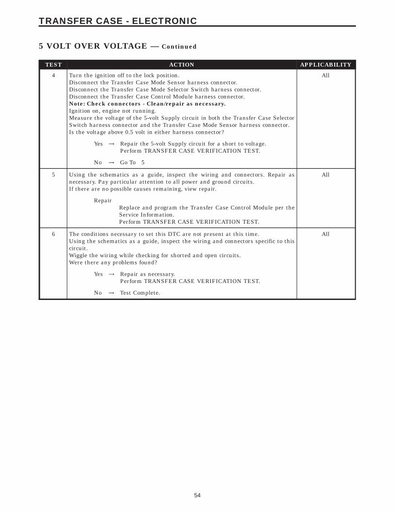
TEST ACTION APPLICABILITY
4 Turn the ignition off to the lock position.Disconnect the Transfer Case Mode Sensor harness connector.Disconnect the Transfer Case Mode Selector Switch harness connector.Disconnect the Transfer Case Control Module harness connector.Note: Check connectors - Clean/repair as necessary.Ignition on, engine not running.Measure the voltage of the 5-volt Supply circuit in both the Transfer Case SelectorSwitch harness connector and the Transfer Case Mode Sensor harness connector.Is the voltage above 0.5 volt in either harness connector?
All
Yes → Repair the 5-volt Supply circuit for a short to voltage.Perform TRANSFER CASE VERIFICATION TEST.
No → Go To 5
5 Using the schematics as a guide, inspect the wiring and connectors. Repair asnecessary. Pay particular attention to all power and ground circuits.If there are no possible causes remaining, view repair.
All
RepairReplace and program the Transfer Case Control Module per theService Information.Perform TRANSFER CASE VERIFICATION TEST.
6 The conditions necessary to set this DTC are not present at this time.Using the schematics as a guide, inspect the wiring and connectors specific to thiscircuit.Wiggle the wiring while checking for shorted and open circuits.Were there any problems found?
All
Yes → Repair as necessary.Perform TRANSFER CASE VERIFICATION TEST.
No → Test Complete.
54
TRANSFER CASE - ELECTRONIC
5 VOLT OVER VOLTAGE — Continued
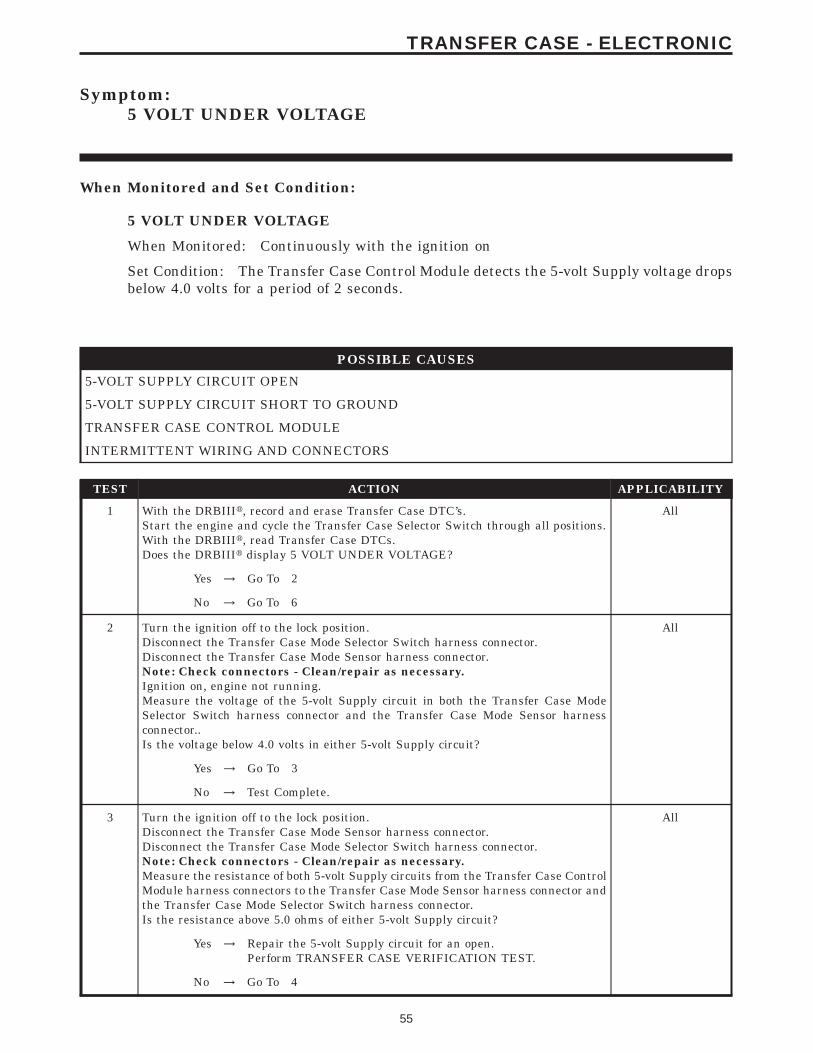
Symptom:5 VOLT UNDER VOLTAGE
When Monitored and Set Condition:
5 VOLT UNDER VOLTAGE
When Monitored: Continuously with the ignition on
Set Condition: The Transfer Case Control Module detects the 5-volt Supply voltage dropsbelow 4.0 volts for a period of 2 seconds.
POSSIBLE CAUSES
5-VOLT SUPPLY CIRCUIT OPEN
5-VOLT SUPPLY CIRCUIT SHORT TO GROUND
TRANSFER CASE CONTROL MODULE
INTERMITTENT WIRING AND CONNECTORS
TEST ACTION APPLICABILITY
1 With the DRBIIIt, record and erase Transfer Case DTC’s.Start the engine and cycle the Transfer Case Selector Switch through all positions.With the DRBIIIt, read Transfer Case DTCs.Does the DRBIIIt display 5 VOLT UNDER VOLTAGE?
All
Yes → Go To 2
No → Go To 6
2 Turn the ignition off to the lock position.Disconnect the Transfer Case Mode Selector Switch harness connector.Disconnect the Transfer Case Mode Sensor harness connector.Note: Check connectors - Clean/repair as necessary.Ignition on, engine not running.Measure the voltage of the 5-volt Supply circuit in both the Transfer Case ModeSelector Switch harness connector and the Transfer Case Mode Sensor harnessconnector..Is the voltage below 4.0 volts in either 5-volt Supply circuit?
All
Yes → Go To 3
No → Test Complete.
3 Turn the ignition off to the lock position.Disconnect the Transfer Case Mode Sensor harness connector.Disconnect the Transfer Case Mode Selector Switch harness connector.Note: Check connectors - Clean/repair as necessary.Measure the resistance of both 5-volt Supply circuits from the Transfer Case ControlModule harness connectors to the Transfer Case Mode Sensor harness connector andthe Transfer Case Mode Selector Switch harness connector.Is the resistance above 5.0 ohms of either 5-volt Supply circuit?
All
Yes → Repair the 5-volt Supply circuit for an open.Perform TRANSFER CASE VERIFICATION TEST.
No → Go To 4
55
TRANSFER CASE - ELECTRONIC
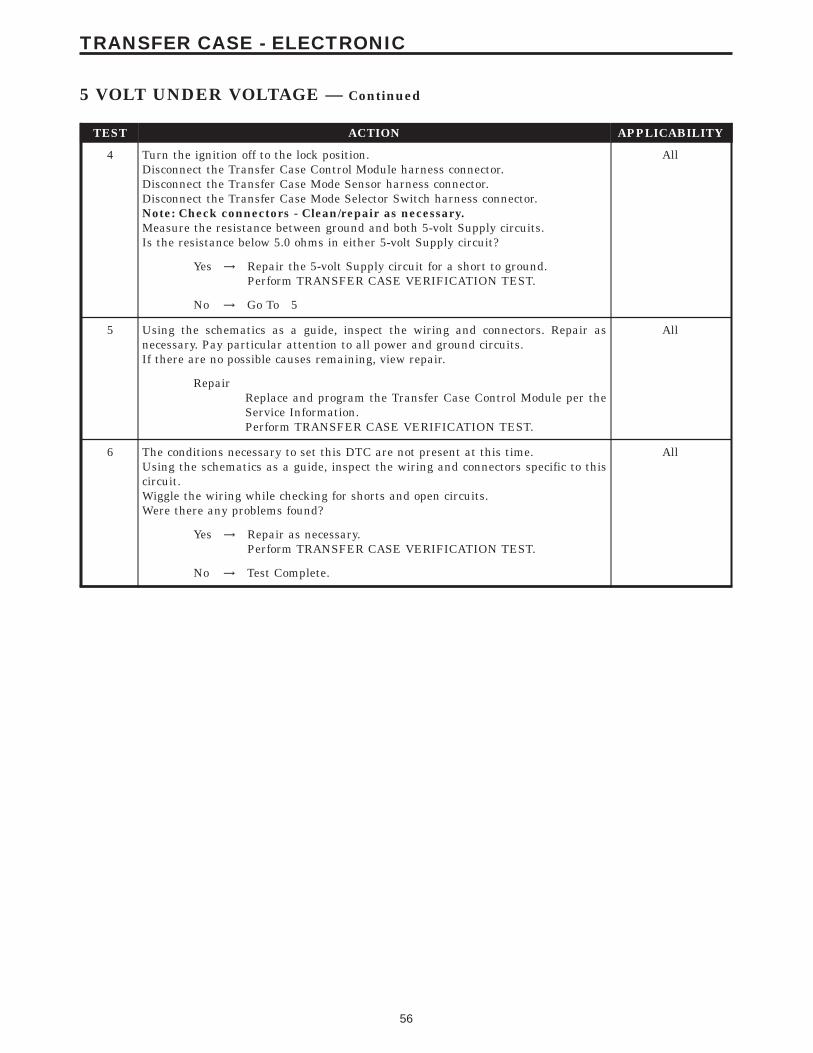
TEST ACTION APPLICABILITY
4 Turn the ignition off to the lock position.Disconnect the Transfer Case Control Module harness connector.Disconnect the Transfer Case Mode Sensor harness connector.Disconnect the Transfer Case Mode Selector Switch harness connector.Note: Check connectors - Clean/repair as necessary.Measure the resistance between ground and both 5-volt Supply circuits.Is the resistance below 5.0 ohms in either 5-volt Supply circuit?
All
Yes → Repair the 5-volt Supply circuit for a short to ground.Perform TRANSFER CASE VERIFICATION TEST.
No → Go To 5
5 Using the schematics as a guide, inspect the wiring and connectors. Repair asnecessary. Pay particular attention to all power and ground circuits.If there are no possible causes remaining, view repair.
All
RepairReplace and program the Transfer Case Control Module per theService Information.Perform TRANSFER CASE VERIFICATION TEST.
6 The conditions necessary to set this DTC are not present at this time.Using the schematics as a guide, inspect the wiring and connectors specific to thiscircuit.Wiggle the wiring while checking for shorts and open circuits.Were there any problems found?
All
Yes → Repair as necessary.Perform TRANSFER CASE VERIFICATION TEST.
No → Test Complete.
56
TRANSFER CASE - ELECTRONIC
5 VOLT UNDER VOLTAGE — Continued
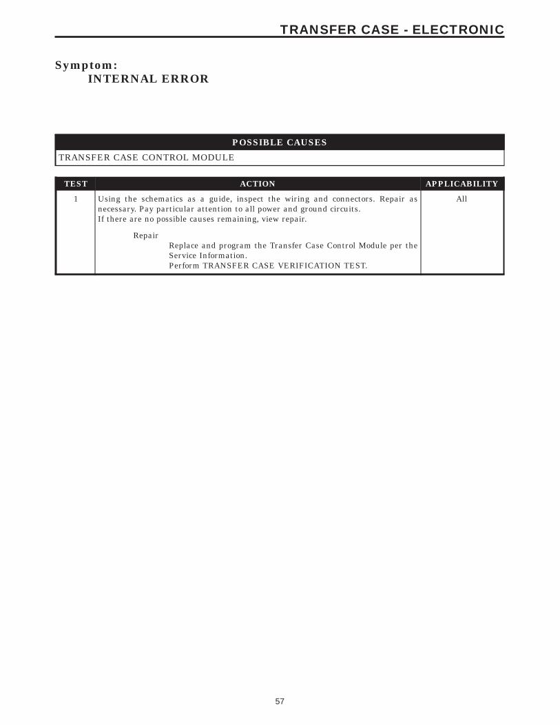
Symptom:INTERNAL ERROR
POSSIBLE CAUSES
TRANSFER CASE CONTROL MODULE
TEST ACTION APPLICABILITY
1 Using the schematics as a guide, inspect the wiring and connectors. Repair asnecessary. Pay particular attention to all power and ground circuits.If there are no possible causes remaining, view repair.
All
RepairReplace and program the Transfer Case Control Module per theService Information.Perform TRANSFER CASE VERIFICATION TEST.
57
TRANSFER CASE - ELECTRONIC
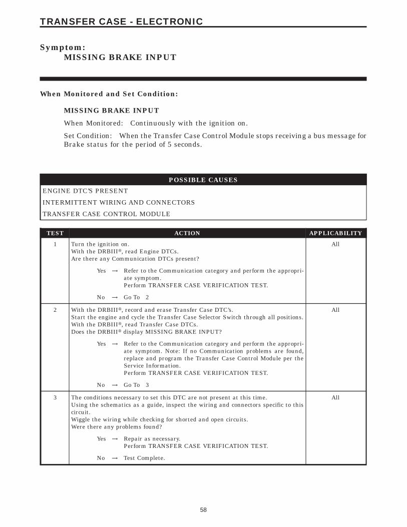
Symptom:MISSING BRAKE INPUT
When Monitored and Set Condition:
MISSING BRAKE INPUT
When Monitored: Continuously with the ignition on.
Set Condition: When the Transfer Case Control Module stops receiving a bus message forBrake status for the period of 5 seconds.
POSSIBLE CAUSES
ENGINE DTC’S PRESENT
INTERMITTENT WIRING AND CONNECTORS
TRANSFER CASE CONTROL MODULE
TEST ACTION APPLICABILITY
1 Turn the ignition on.With the DRBIIIt, read Engine DTCs.Are there any Communication DTCs present?
All
Yes → Refer to the Communication category and perform the appropri-ate symptom.Perform TRANSFER CASE VERIFICATION TEST.
No → Go To 2
2 With the DRBIIIt, record and erase Transfer Case DTC’s.Start the engine and cycle the Transfer Case Selector Switch through all positions.With the DRBIIIt, read Transfer Case DTCs.Does the DRBIIIt display MISSING BRAKE INPUT?
All
Yes → Refer to the Communication category and perform the appropri-ate symptom. Note: If no Communication problems are found,replace and program the Transfer Case Control Module per theService Information.Perform TRANSFER CASE VERIFICATION TEST.
No → Go To 3
3 The conditions necessary to set this DTC are not present at this time.Using the schematics as a guide, inspect the wiring and connectors specific to thiscircuit.Wiggle the wiring while checking for shorted and open circuits.Were there any problems found?
All
Yes → Repair as necessary.Perform TRANSFER CASE VERIFICATION TEST.
No → Test Complete.
58
TRANSFER CASE - ELECTRONIC
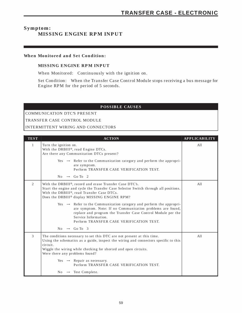
Symptom:MISSING ENGINE RPM INPUT
When Monitored and Set Condition:
MISSING ENGINE RPM INPUT
When Monitored: Continuously with the ignition on.
Set Condition: When the Transfer Case Control Module stops receiving a bus message forEngine RPM for the period of 5 seconds.
POSSIBLE CAUSES
COMMUNICATION DTC’S PRESENT
TRANSFER CASE CONTROL MODULE
INTERMITTENT WIRING AND CONNECTORS
TEST ACTION APPLICABILITY
1 Turn the ignition on.With the DRBIIIt, read Engine DTCs.Are there any Communication DTCs present?
All
Yes → Refer to the Communication category and perform the appropri-ate symptom.Perform TRANSFER CASE VERIFICATION TEST.
No → Go To 2
2 With the DRBIIIt, record and erase Transfer Case DTC’s.Start the engine and cycle the Transfer Case Selector Switch through all positions.With the DRBIIIt, read Transfer Case DTCs.Does the DRBIIIt display MISSING ENGINE RPM?
All
Yes → Refer to the Communication category and perform the appropri-ate symptom. Note: If no Communication problems are found,replace and program the Transfer Case Control Module per theService Information.Perform TRANSFER CASE VERIFICATION TEST.
No → Go To 3
3 The conditions necessary to set this DTC are not present at this time.Using the schematics as a guide, inspect the wiring and connectors specific to thiscircuit.Wiggle the wiring while checking for shorted and open circuits.Were there any problems found?
All
Yes → Repair as necessary.Perform TRANSFER CASE VERIFICATION TEST.
No → Test Complete.
59
TRANSFER CASE - ELECTRONIC
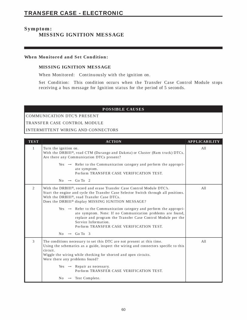
Symptom:MISSING IGNITION MESSAGE
When Monitored and Set Condition:
MISSING IGNITION MESSAGE
When Monitored: Continuously with the ignition on.
Set Condition: This condition occurs when the Transfer Case Control Module stopsreceiving a bus message for Ignition status for the period of 5 seconds.
POSSIBLE CAUSES
COMMUNICATION DTC’S PRESENT
TRANSFER CASE CONTROL MODULE
INTERMITTENT WIRING AND CONNECTORS
TEST ACTION APPLICABILITY
1 Turn the ignition on.With the DRBIIIt, read CTM (Durango and Dakota) or Cluster (Ram truck) DTCs.Are there any Communication DTCs present?
All
Yes → Refer to the Communication category and perform the appropri-ate symptom.Perform TRANSFER CASE VERIFICATION TEST.
No → Go To 2
2 With the DRBIIIt, record and erase Transfer Case Control Module DTC’s.Start the engine and cycle the Transfer Case Selector Switch through all positions.With the DRBIIIt, read Transfer Case DTCs.Does the DRBIIIt display MISSING IGNITION MESSAGE?
All
Yes → Refer to the Communication category and perform the appropri-ate symptom. Note: If no Communication problems are found,replace and program the Transfer Case Control Module per theService Information.Perform TRANSFER CASE VERIFICATION TEST.
No → Go To 3
3 The conditions necessary to set this DTC are not present at this time.Using the schematics as a guide, inspect the wiring and connectors specific to thiscircuit.Wiggle the wiring while checking for shorted and open circuits.Were there any problems found?
All
Yes → Repair as necessary.Perform TRANSFER CASE VERIFICATION TEST.
No → Test Complete.
60
TRANSFER CASE - ELECTRONIC
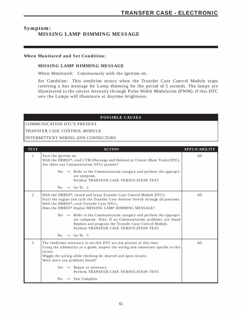
Symptom:MISSING LAMP DIMMING MESSAGE
When Monitored and Set Condition:
MISSING LAMP DIMMING MESSAGE
When Monitored: Continuously with the ignition on.
Set Condition: This condition occurs when the Transfer Case Control Module stopsreceiving a bus message for Lamp dimming for the period of 5 seconds. The lamps areilluminated to the correct intensity through Pulse Width Modulation (PWM). If this DTCsets the Lamps will illuminate at daytime brightness.
POSSIBLE CAUSES
COMMUNICATION DTC’S PRESENT
TRANSFER CASE CONTROL MODULE
INTERMITTENT WIRING AND CONNECTORS
TEST ACTION APPLICABILITY
1 Turn the ignition on.With the DRBIIIt, read CTM (Durango and Dakota) or Cluster (Ram Truck) DTCs.Are there any Communication DTCs present?
All
Yes → Refer to the Communication category and perform the appropri-ate symptom.Perform TRANSFER CASE VERIFICATION TEST.
No → Go To 2
2 With the DRBIIIt, record and erase Transfer Case Control Module DTC’s.Start the engine and cycle the Transfer Case Selector Switch through all positions.With the DRBIIIt, read Transfer Case DTCs.Does the DRBIIIt display MISSING LAMP DIMMING MESSAGE?
All
Yes → Refer to the Communication category and perform the appropri-ate symptom. Note: If no Communication problems are foundReplace and program the Transfer Case Control Module.Perform TRANSFER CASE VERIFICATION TEST.
No → Go To 3
3 The conditions necessary to set this DTC are not present at this time.Using the schematics as a guide, inspect the wiring and connectors specific to thiscircuit.Wiggle the wiring while checking for shorted and open circuits.Were there any problems found?
All
Yes → Repair as necessary.Perform TRANSFER CASE VERIFICATION TEST.
No → Test Complete.
61
TRANSFER CASE - ELECTRONIC
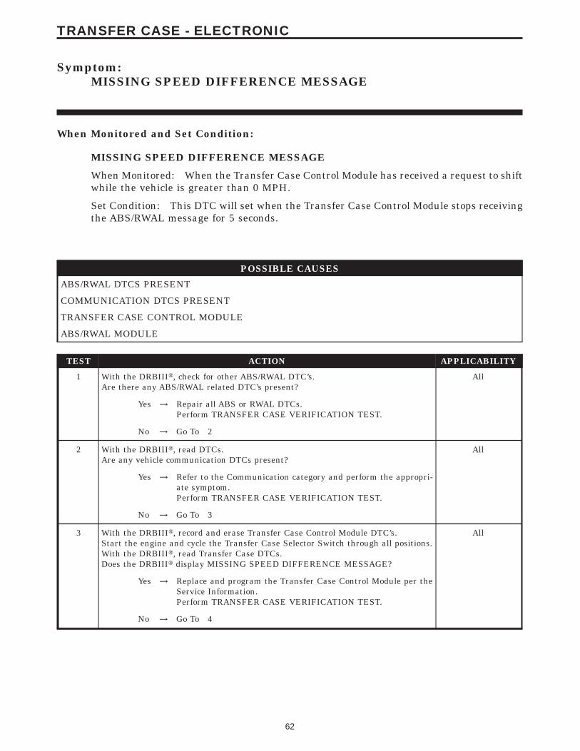
Symptom:MISSING SPEED DIFFERENCE MESSAGE
When Monitored and Set Condition:
MISSING SPEED DIFFERENCE MESSAGE
When Monitored: When the Transfer Case Control Module has received a request to shiftwhile the vehicle is greater than 0 MPH.
Set Condition: This DTC will set when the Transfer Case Control Module stops receivingthe ABS/RWAL message for 5 seconds.
POSSIBLE CAUSES
ABS/RWAL DTCS PRESENT
COMMUNICATION DTCS PRESENT
TRANSFER CASE CONTROL MODULE
ABS/RWAL MODULE
TEST ACTION APPLICABILITY
1 With the DRBIIIt, check for other ABS/RWAL DTC’s.Are there any ABS/RWAL related DTC’s present?
All
Yes → Repair all ABS or RWAL DTCs.Perform TRANSFER CASE VERIFICATION TEST.
No → Go To 2
2 With the DRBIIIt, read DTCs.Are any vehicle communication DTCs present?
All
Yes → Refer to the Communication category and perform the appropri-ate symptom.Perform TRANSFER CASE VERIFICATION TEST.
No → Go To 3
3 With the DRBIIIt, record and erase Transfer Case Control Module DTC’s.Start the engine and cycle the Transfer Case Selector Switch through all positions.With the DRBIIIt, read Transfer Case DTCs.Does the DRBIIIt display MISSING SPEED DIFFERENCE MESSAGE?
All
Yes → Replace and program the Transfer Case Control Module per theService Information.Perform TRANSFER CASE VERIFICATION TEST.
No → Go To 4
62
TRANSFER CASE - ELECTRONIC

TEST ACTION APPLICABILITY
4 Using the schematics as a guide, inspect the wiring and connectors. Pay particularattention to corroded terminals and all power and ground circuits. Repair asnecessary.Verify the flash level of the controller and update the controller if available.Check for any Technical Service Bulletins (TSB’s) and S.T.A.R. ON-LINE for anypossible causes that may apply.If there are no possible causes remaining, view repair.
All
RepairReplace and program the ABS or RWAL module per the serviceinformation.Perform TRANSFER CASE VERIFICATION TEST.
63
TRANSFER CASE - ELECTRONIC
MISSING SPEED DIFFERENCE MESSAGE — Continued

Symptom:MISSING TRANSFER CASE TYPE
When Monitored and Set Condition:
MISSING TRANSFER CASE TYPE
When Monitored: Continuously with the ignition on.
Set Condition: When the Transfer Case Control Module stops receiving a bus messageidentifying the transfer case type for the period of 5 seconds.
POSSIBLE CAUSES
COMMUNICATION DTC’S PRESENT
TRANSFER CASE CONTROL MODULE
INTERMITTENT WIRING AND CONNECTORS
TEST ACTION APPLICABILITY
1 Turn the ignition on.With the DRBIIIt, read Engine DTCs.Are there any Communication DTCs present?
All
Yes → Refer to the Communication category and perform the appropri-ate symptom.Perform TRANSFER CASE VERIFICATION TEST.
No → Go To 2
2 With the DRBIIIt, record and erase Transfer Case Control Module DTC’s.Start the engine and cycle the Transfer Case Selector Switch through all positions.With the DRBIIIt, read Transfer Case DTCs.Does the DRBIIIt display MISSING TRANSFER CASE TYPE?
All
Yes → Refer to the Communication category and perform the appropri-ate symptom. Note: If no Communication problems are found,replace and program the Transfer Case Control Module per theService Information.Perform TRANSFER CASE VERIFICATION TEST.
No → Go To 3
3 The conditions necessary to set this DTC are not present at this time.Using the schematics as a guide, inspect the wiring and connectors specific to thiscircuit.Wiggle the wiring while checking for shorted and open circuits.Were there any problems found?
All
Yes → Repair as necessary.Perform TRANSFER CASE VERIFICATION TEST.
No → Test Complete.
64
TRANSFER CASE - ELECTRONIC
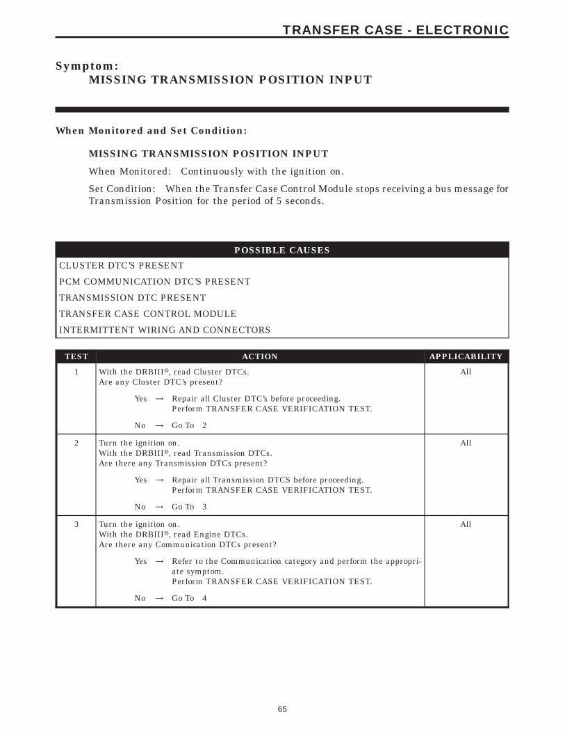
Symptom:MISSING TRANSMISSION POSITION INPUT
When Monitored and Set Condition:
MISSING TRANSMISSION POSITION INPUT
When Monitored: Continuously with the ignition on.
Set Condition: When the Transfer Case Control Module stops receiving a bus message forTransmission Position for the period of 5 seconds.
POSSIBLE CAUSES
CLUSTER DTC’S PRESENT
PCM COMMUNICATION DTC’S PRESENT
TRANSMISSION DTC PRESENT
TRANSFER CASE CONTROL MODULE
INTERMITTENT WIRING AND CONNECTORS
TEST ACTION APPLICABILITY
1 With the DRBIIIt, read Cluster DTCs.Are any Cluster DTC’s present?
All
Yes → Repair all Cluster DTC’s before proceeding.Perform TRANSFER CASE VERIFICATION TEST.
No → Go To 2
2 Turn the ignition on.With the DRBIIIt, read Transmission DTCs.Are there any Transmission DTCs present?
All
Yes → Repair all Transmission DTCS before proceeding.Perform TRANSFER CASE VERIFICATION TEST.
No → Go To 3
3 Turn the ignition on.With the DRBIIIt, read Engine DTCs.Are there any Communication DTCs present?
All
Yes → Refer to the Communication category and perform the appropri-ate symptom.Perform TRANSFER CASE VERIFICATION TEST.
No → Go To 4
65
TRANSFER CASE - ELECTRONIC
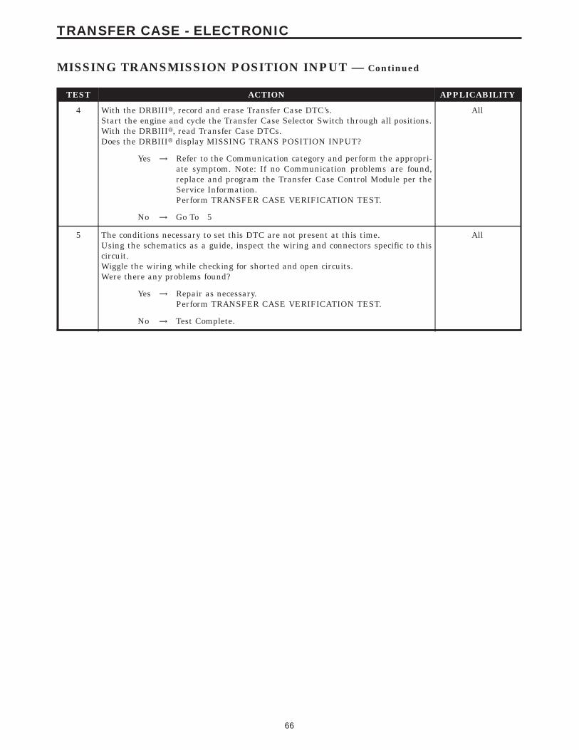
TEST ACTION APPLICABILITY
4 With the DRBIIIt, record and erase Transfer Case DTC’s.Start the engine and cycle the Transfer Case Selector Switch through all positions.With the DRBIIIt, read Transfer Case DTCs.Does the DRBIIIt display MISSING TRANS POSITION INPUT?
All
Yes → Refer to the Communication category and perform the appropri-ate symptom. Note: If no Communication problems are found,replace and program the Transfer Case Control Module per theService Information.Perform TRANSFER CASE VERIFICATION TEST.
No → Go To 5
5 The conditions necessary to set this DTC are not present at this time.Using the schematics as a guide, inspect the wiring and connectors specific to thiscircuit.Wiggle the wiring while checking for shorted and open circuits.Were there any problems found?
All
Yes → Repair as necessary.Perform TRANSFER CASE VERIFICATION TEST.
No → Test Complete.
66
TRANSFER CASE - ELECTRONIC
MISSING TRANSMISSION POSITION INPUT — Continued
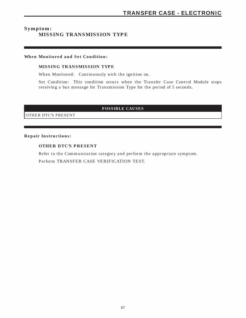
Symptom:MISSING TRANSMISSION TYPE
When Monitored and Set Condition:
MISSING TRANSMISSION TYPE
When Monitored: Continuously with the ignition on.
Set Condition: This condition occurs when the Transfer Case Control Module stopsreceiving a bus message for Transmission Type for the period of 5 seconds.
POSSIBLE CAUSES
OTHER DTC’S PRESENT
Repair Instructions:
OTHER DTC’S PRESENT
Refer to the Communication category and perform the appropriate symptom.
Perform TRANSFER CASE VERIFICATION TEST.
67
TRANSFER CASE - ELECTRONIC
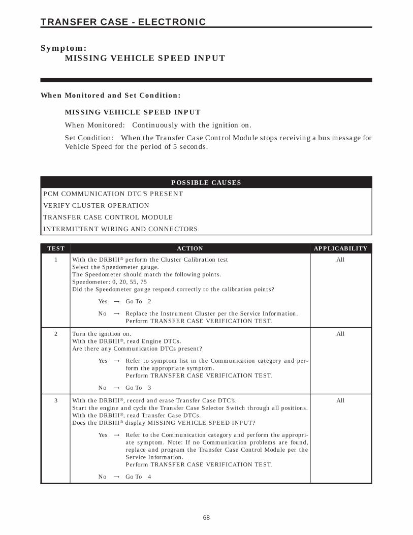
Symptom:MISSING VEHICLE SPEED INPUT
When Monitored and Set Condition:
MISSING VEHICLE SPEED INPUT
When Monitored: Continuously with the ignition on.
Set Condition: When the Transfer Case Control Module stops receiving a bus message forVehicle Speed for the period of 5 seconds.
POSSIBLE CAUSES
PCM COMMUNICATION DTC’S PRESENT
VERIFY CLUSTER OPERATION
TRANSFER CASE CONTROL MODULE
INTERMITTENT WIRING AND CONNECTORS
TEST ACTION APPLICABILITY
1 With the DRBIIIt perform the Cluster Calibration testSelect the Speedometer gauge.The Speedometer should match the following points.Speedometer: 0, 20, 55, 75Did the Speedometer gauge respond correctly to the calibration points?
All
Yes → Go To 2
No → Replace the Instrument Cluster per the Service Information.Perform TRANSFER CASE VERIFICATION TEST.
2 Turn the ignition on.With the DRBIIIt, read Engine DTCs.Are there any Communication DTCs present?
All
Yes → Refer to symptom list in the Communication category and per-form the appropriate symptom.Perform TRANSFER CASE VERIFICATION TEST.
No → Go To 3
3 With the DRBIIIt, record and erase Transfer Case DTC’s.Start the engine and cycle the Transfer Case Selector Switch through all positions.With the DRBIIIt, read Transfer Case DTCs.Does the DRBIIIt display MISSING VEHICLE SPEED INPUT?
All
Yes → Refer to the Communication category and perform the appropri-ate symptom. Note: If no Communication problems are found,replace and program the Transfer Case Control Module per theService Information.Perform TRANSFER CASE VERIFICATION TEST.
No → Go To 4
68
TRANSFER CASE - ELECTRONIC
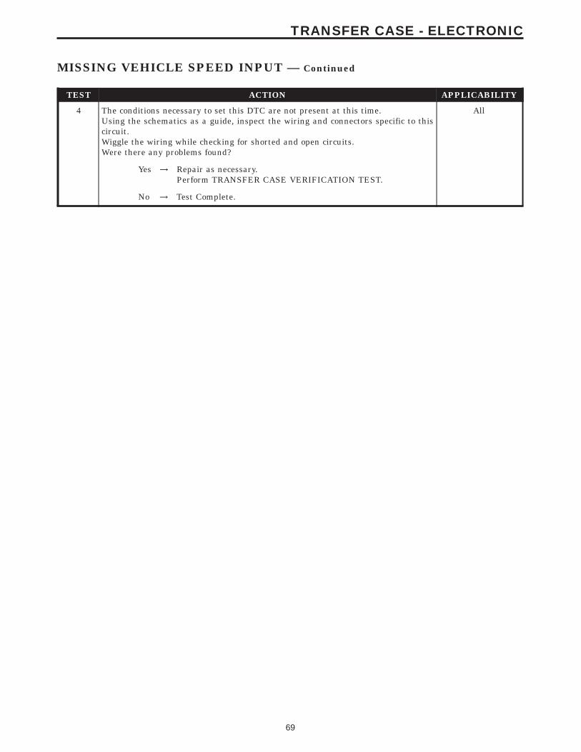
TEST ACTION APPLICABILITY
4 The conditions necessary to set this DTC are not present at this time.Using the schematics as a guide, inspect the wiring and connectors specific to thiscircuit.Wiggle the wiring while checking for shorted and open circuits.Were there any problems found?
All
Yes → Repair as necessary.Perform TRANSFER CASE VERIFICATION TEST.
No → Test Complete.
69
TRANSFER CASE - ELECTRONIC
MISSING VEHICLE SPEED INPUT — Continued

Symptom:NEUTRAL INDICATOR OPEN
When Monitored and Set Condition:
NEUTRAL INDICATOR OPEN
When Monitored: Continuously with the ignition on.
Set Condition: The Transfer Case Control Module detects an open in the NeutralIndicator circuit.
POSSIBLE CAUSES
FUSED IGNITION SWITCH OUTPUT CIRCUIT OPEN
NEUTRAL INDICATOR CIRCUIT OPEN
NEUTRAL INDICATOR CIRCUIT SHORT TO VOLTAGE
TRANSFER CASE SELECTOR SWITCH
TRANSFER CASE CONTROL MODULE
INTERMITTENT WIRING AND CONNECTORS
TEST ACTION APPLICABILITY
1 With the DRBIIIt, record and erase Transfer Case DTC’s.Start the engine and cycle the Transfer Case Selector Switch through all positions.With the DRBIIIt, read Transfer Case DTCs.Does the DRBIIIt display NEUTRAL INDICATOR OPEN?
All
Yes → Go To 2
No → Go To 7
2 Turn the ignition off to the lock position.Disconnect the Transfer Case Control Module harness connector.Disconnect the Transfer Case Selector Switch harness connector.Note: Check connectors - Clean/repair as necessary.Measure the resistance of the Neutral Indicator circuit from the Transfer CaseControl Module harness connector to the Transfer Case Selector Switch harnessconnector.Is the resistance above 5.0 ohms?
All
Yes → Repair the Neutral Indicator circuit for an open.Perform TRANSFER CASE VERIFICATION TEST.
No → Go To 3
70
TRANSFER CASE - ELECTRONIC
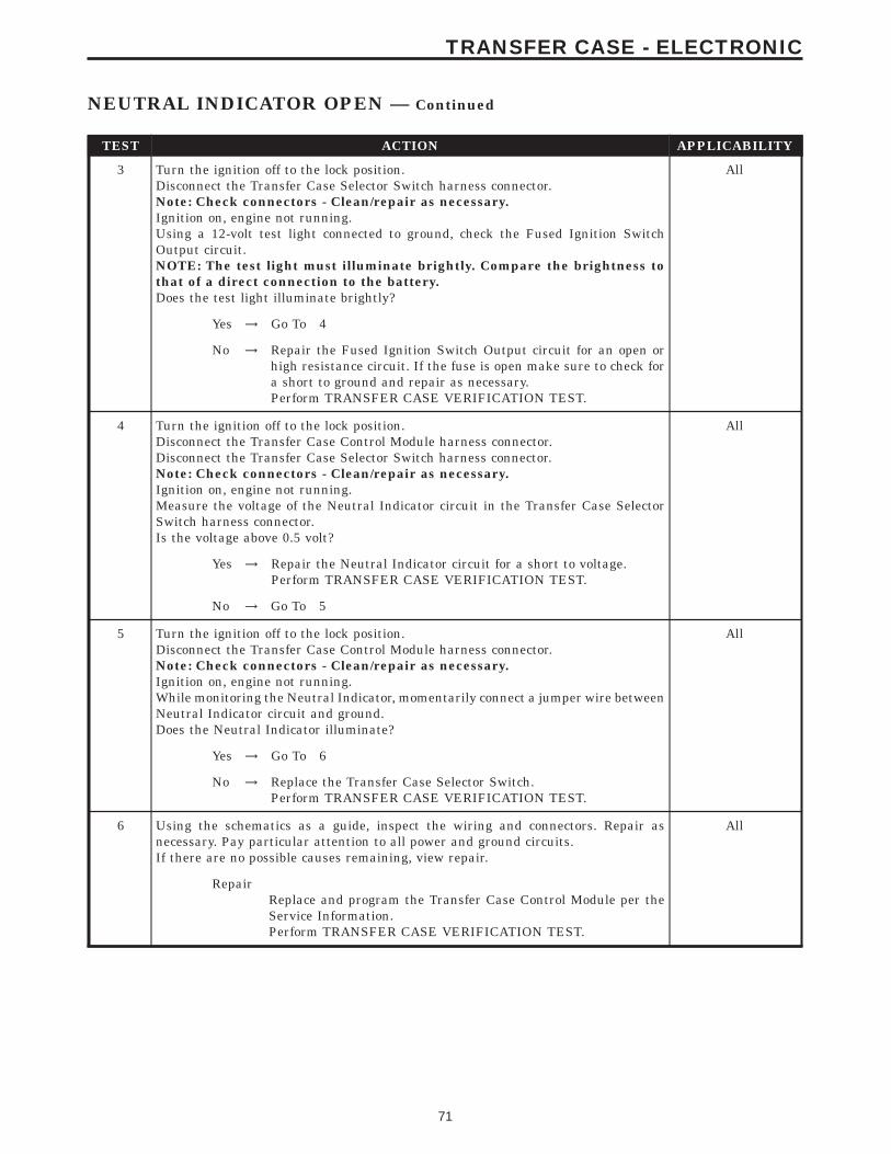
TEST ACTION APPLICABILITY
3 Turn the ignition off to the lock position.Disconnect the Transfer Case Selector Switch harness connector.Note: Check connectors - Clean/repair as necessary.Ignition on, engine not running.Using a 12-volt test light connected to ground, check the Fused Ignition SwitchOutput circuit.NOTE: The test light must illuminate brightly. Compare the brightness tothat of a direct connection to the battery.Does the test light illuminate brightly?
All
Yes → Go To 4
No → Repair the Fused Ignition Switch Output circuit for an open orhigh resistance circuit. If the fuse is open make sure to check fora short to ground and repair as necessary.Perform TRANSFER CASE VERIFICATION TEST.
4 Turn the ignition off to the lock position.Disconnect the Transfer Case Control Module harness connector.Disconnect the Transfer Case Selector Switch harness connector.Note: Check connectors - Clean/repair as necessary.Ignition on, engine not running.Measure the voltage of the Neutral Indicator circuit in the Transfer Case SelectorSwitch harness connector.Is the voltage above 0.5 volt?
All
Yes → Repair the Neutral Indicator circuit for a short to voltage.Perform TRANSFER CASE VERIFICATION TEST.
No → Go To 5
5 Turn the ignition off to the lock position.Disconnect the Transfer Case Control Module harness connector.Note: Check connectors - Clean/repair as necessary.Ignition on, engine not running.While monitoring the Neutral Indicator, momentarily connect a jumper wire betweenNeutral Indicator circuit and ground.Does the Neutral Indicator illuminate?
All
Yes → Go To 6
No → Replace the Transfer Case Selector Switch.Perform TRANSFER CASE VERIFICATION TEST.
6 Using the schematics as a guide, inspect the wiring and connectors. Repair asnecessary. Pay particular attention to all power and ground circuits.If there are no possible causes remaining, view repair.
All
RepairReplace and program the Transfer Case Control Module per theService Information.Perform TRANSFER CASE VERIFICATION TEST.
71
TRANSFER CASE - ELECTRONIC
NEUTRAL INDICATOR OPEN — Continued

TEST ACTION APPLICABILITY
7 The conditions necessary to set this DTC are not present at this time.Using the schematics as a guide, inspect the wiring and connectors specific to thiscircuit.Wiggle the wiring while checking for shorts and open circuits.Were there any problems found?
All
Yes → Repair as necessary.Perform TRANSFER CASE VERIFICATION TEST.
No → Test Complete.
72
TRANSFER CASE - ELECTRONIC
NEUTRAL INDICATOR OPEN — Continued
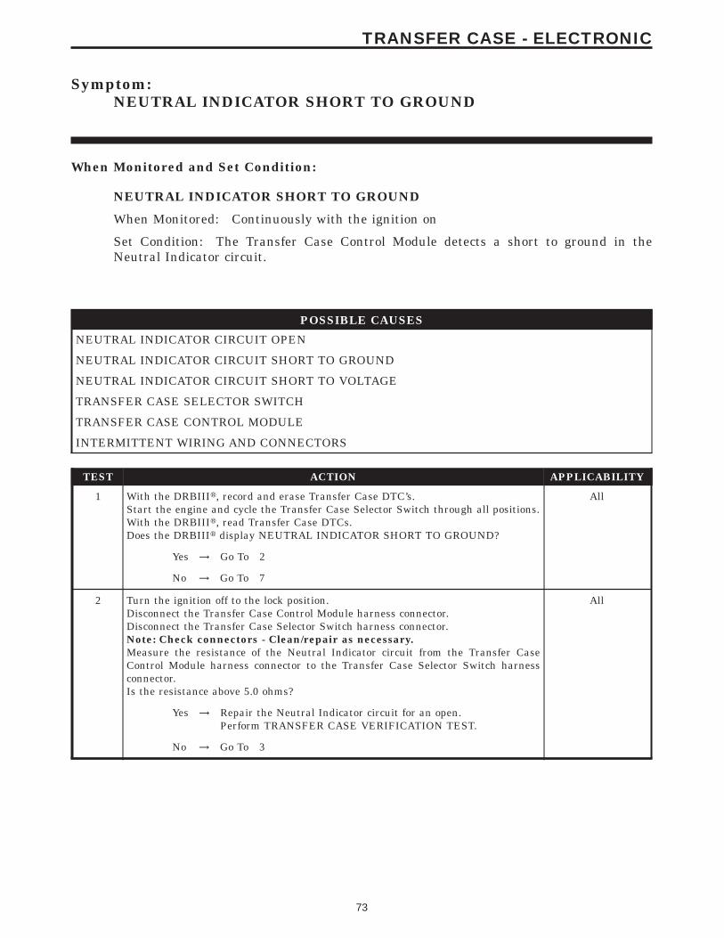
Symptom:NEUTRAL INDICATOR SHORT TO GROUND
When Monitored and Set Condition:
NEUTRAL INDICATOR SHORT TO GROUND
When Monitored: Continuously with the ignition on
Set Condition: The Transfer Case Control Module detects a short to ground in theNeutral Indicator circuit.
POSSIBLE CAUSES
NEUTRAL INDICATOR CIRCUIT OPEN
NEUTRAL INDICATOR CIRCUIT SHORT TO GROUND
NEUTRAL INDICATOR CIRCUIT SHORT TO VOLTAGE
TRANSFER CASE SELECTOR SWITCH
TRANSFER CASE CONTROL MODULE
INTERMITTENT WIRING AND CONNECTORS
TEST ACTION APPLICABILITY
1 With the DRBIIIt, record and erase Transfer Case DTC’s.Start the engine and cycle the Transfer Case Selector Switch through all positions.With the DRBIIIt, read Transfer Case DTCs.Does the DRBIIIt display NEUTRAL INDICATOR SHORT TO GROUND?
All
Yes → Go To 2
No → Go To 7
2 Turn the ignition off to the lock position.Disconnect the Transfer Case Control Module harness connector.Disconnect the Transfer Case Selector Switch harness connector.Note: Check connectors - Clean/repair as necessary.Measure the resistance of the Neutral Indicator circuit from the Transfer CaseControl Module harness connector to the Transfer Case Selector Switch harnessconnector.Is the resistance above 5.0 ohms?
All
Yes → Repair the Neutral Indicator circuit for an open.Perform TRANSFER CASE VERIFICATION TEST.
No → Go To 3
73
TRANSFER CASE - ELECTRONIC
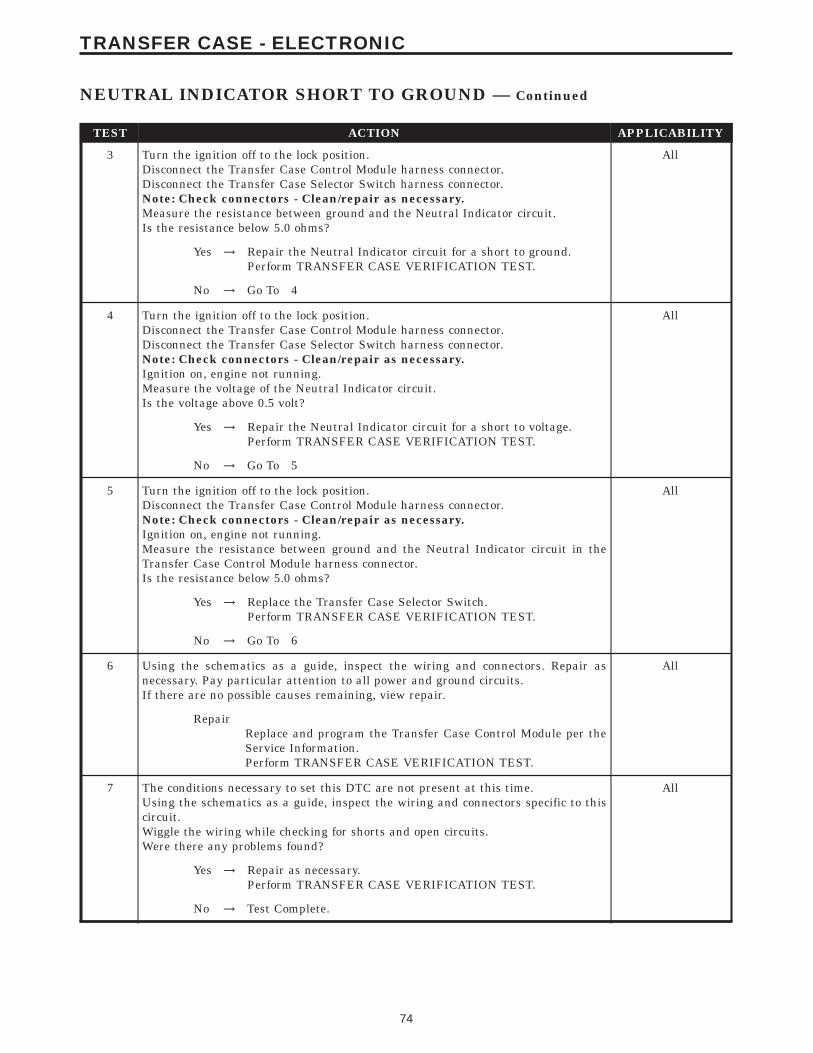
TEST ACTION APPLICABILITY
3 Turn the ignition off to the lock position.Disconnect the Transfer Case Control Module harness connector.Disconnect the Transfer Case Selector Switch harness connector.Note: Check connectors - Clean/repair as necessary.Measure the resistance between ground and the Neutral Indicator circuit.Is the resistance below 5.0 ohms?
All
Yes → Repair the Neutral Indicator circuit for a short to ground.Perform TRANSFER CASE VERIFICATION TEST.
No → Go To 4
4 Turn the ignition off to the lock position.Disconnect the Transfer Case Control Module harness connector.Disconnect the Transfer Case Selector Switch harness connector.Note: Check connectors - Clean/repair as necessary.Ignition on, engine not running.Measure the voltage of the Neutral Indicator circuit.Is the voltage above 0.5 volt?
All
Yes → Repair the Neutral Indicator circuit for a short to voltage.Perform TRANSFER CASE VERIFICATION TEST.
No → Go To 5
5 Turn the ignition off to the lock position.Disconnect the Transfer Case Control Module harness connector.Note: Check connectors - Clean/repair as necessary.Ignition on, engine not running.Measure the resistance between ground and the Neutral Indicator circuit in theTransfer Case Control Module harness connector.Is the resistance below 5.0 ohms?
All
Yes → Replace the Transfer Case Selector Switch.Perform TRANSFER CASE VERIFICATION TEST.
No → Go To 6
6 Using the schematics as a guide, inspect the wiring and connectors. Repair asnecessary. Pay particular attention to all power and ground circuits.If there are no possible causes remaining, view repair.
All
RepairReplace and program the Transfer Case Control Module per theService Information.Perform TRANSFER CASE VERIFICATION TEST.
7 The conditions necessary to set this DTC are not present at this time.Using the schematics as a guide, inspect the wiring and connectors specific to thiscircuit.Wiggle the wiring while checking for shorts and open circuits.Were there any problems found?
All
Yes → Repair as necessary.Perform TRANSFER CASE VERIFICATION TEST.
No → Test Complete.
74
TRANSFER CASE - ELECTRONIC
NEUTRAL INDICATOR SHORT TO GROUND — Continued
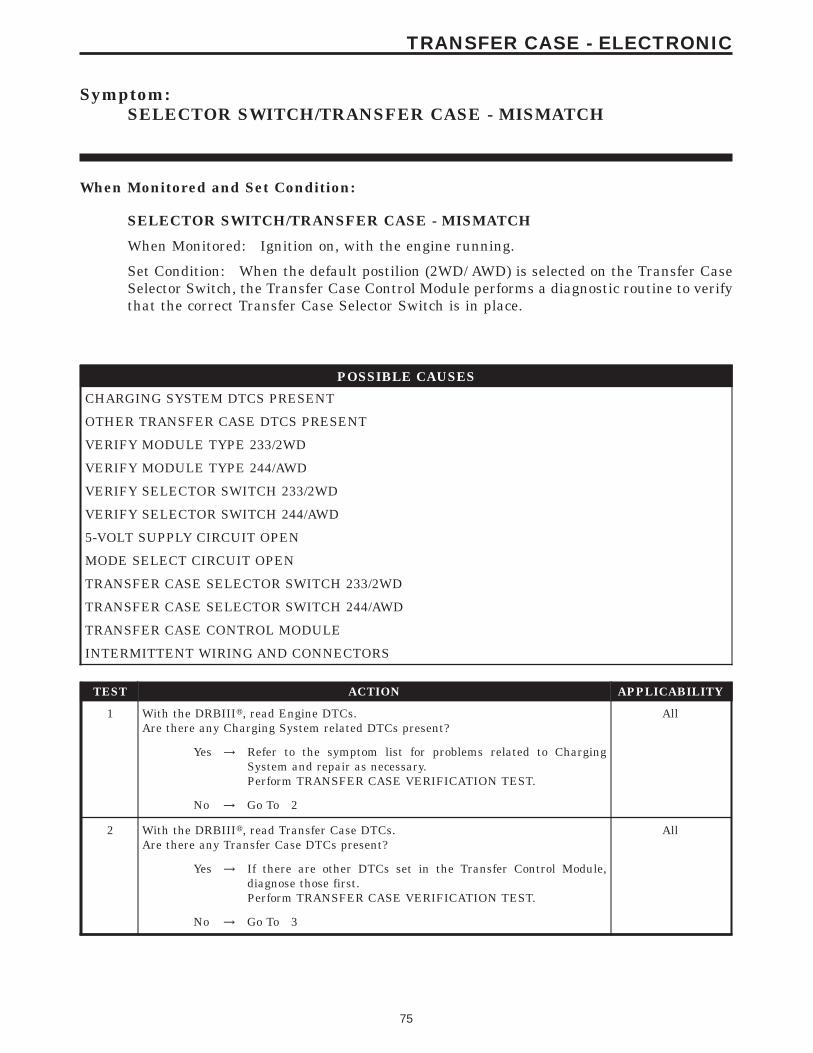
Symptom:SELECTOR SWITCH/TRANSFER CASE - MISMATCH
When Monitored and Set Condition:
SELECTOR SWITCH/TRANSFER CASE - MISMATCH
When Monitored: Ignition on, with the engine running.
Set Condition: When the default postilion (2WD/ AWD) is selected on the Transfer CaseSelector Switch, the Transfer Case Control Module performs a diagnostic routine to verifythat the correct Transfer Case Selector Switch is in place.
POSSIBLE CAUSES
CHARGING SYSTEM DTCS PRESENT
OTHER TRANSFER CASE DTCS PRESENT
VERIFY MODULE TYPE 233/2WD
VERIFY MODULE TYPE 244/AWD
VERIFY SELECTOR SWITCH 233/2WD
VERIFY SELECTOR SWITCH 244/AWD
5-VOLT SUPPLY CIRCUIT OPEN
MODE SELECT CIRCUIT OPEN
TRANSFER CASE SELECTOR SWITCH 233/2WD
TRANSFER CASE SELECTOR SWITCH 244/AWD
TRANSFER CASE CONTROL MODULE
INTERMITTENT WIRING AND CONNECTORS
TEST ACTION APPLICABILITY
1 With the DRBIIIt, read Engine DTCs.Are there any Charging System related DTCs present?
All
Yes → Refer to the symptom list for problems related to ChargingSystem and repair as necessary.Perform TRANSFER CASE VERIFICATION TEST.
No → Go To 2
2 With the DRBIIIt, read Transfer Case DTCs.Are there any Transfer Case DTCs present?
All
Yes → If there are other DTCs set in the Transfer Control Module,diagnose those first.Perform TRANSFER CASE VERIFICATION TEST.
No → Go To 3
75
TRANSFER CASE - ELECTRONIC
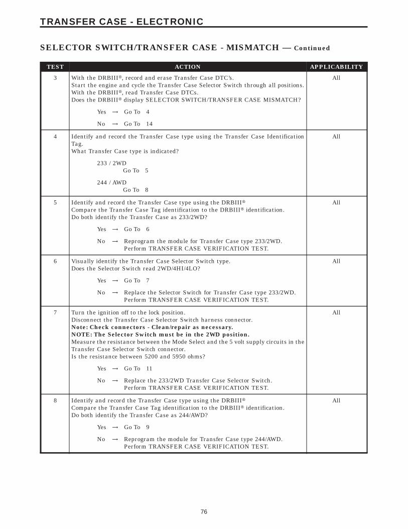
TEST ACTION APPLICABILITY
3 With the DRBIIIt, record and erase Transfer Case DTC’s.Start the engine and cycle the Transfer Case Selector Switch through all positions.With the DRBIIIt, read Transfer Case DTCs.Does the DRBIIIt display SELECTOR SWITCH/TRANSFER CASE MISMATCH?
All
Yes → Go To 4
No → Go To 14
4 Identify and record the Transfer Case type using the Transfer Case IdentificationTag.What Transfer Case type is indicated?
All
233 / 2WDGo To 5
244 / AWDGo To 8
5 Identify and record the Transfer Case type using the DRBIIItCompare the Transfer Case Tag identification to the DRBIIIt identification.Do both identify the Transfer Case as 233/2WD?
All
Yes → Go To 6
No → Reprogram the module for Transfer Case type 233/2WD.Perform TRANSFER CASE VERIFICATION TEST.
6 Visually identify the Transfer Case Selector Switch type.Does the Selector Switch read 2WD/4HI/4LO?
All
Yes → Go To 7
No → Replace the Selector Switch for Transfer Case type 233/2WD.Perform TRANSFER CASE VERIFICATION TEST.
7 Turn the ignition off to the lock position.Disconnect the Transfer Case Selector Switch harness connector.Note: Check connectors - Clean/repair as necessary.NOTE: The Selector Switch must be in the 2WD position.Measure the resistance between the Mode Select and the 5 volt supply circuits in theTransfer Case Selector Switch connector.Is the resistance between 5200 and 5950 ohms?
All
Yes → Go To 11
No → Replace the 233/2WD Transfer Case Selector Switch.Perform TRANSFER CASE VERIFICATION TEST.
8 Identify and record the Transfer Case type using the DRBIIItCompare the Transfer Case Tag identification to the DRBIIIt identification.Do both identify the Transfer Case as 244/AWD?
All
Yes → Go To 9
No → Reprogram the module for Transfer Case type 244/AWD.Perform TRANSFER CASE VERIFICATION TEST.
76
TRANSFER CASE - ELECTRONIC
SELECTOR SWITCH/TRANSFER CASE - MISMATCH — Continued
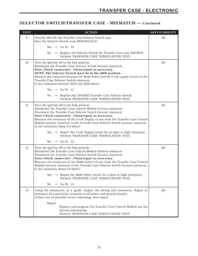
TEST ACTION APPLICABILITY
9 Visually identify the Transfer Case Selector Switch type.Does the Selector Switch read AWD/4HI/4LO?
All
Yes → Go To 10
No → Replace the Selector Switch for Transfer Case type 244/AWD.Perform TRANSFER CASE VERIFICATION TEST.
10 Turn the ignition off to the lock position.Disconnect the Transfer Case Selector Switch harness connector.Note: Check connectors - Clean/repair as necessary.NOTE: The Selector Switch must be in the AWD position.Measure the resistance between the Mode Select and the 5 volt supply circuits in theTransfer Case Selector Switch connector.Is the resistance between 3050 and 3600 ohms?
All
Yes → Go To 11
No → Replace the 244/AWD Transfer Case Selector Switch.Perform TRANSFER CASE VERIFICATION TEST.
11 Turn the ignition off to the lock position.Disconnect the Transfer Case Control Module harness connector.Disconnect the Transfer Case Selector Switch harness connector.Note: Check connectors - Clean/repair as necessary.Measure the resistance of the 5-volt Supply circuit from the Transfer Case ControlModule harness connector to the Transfer Case Selector Switch harness connector.Is the resistance above 5.0 ohms?
All
Yes → Repair the 5-volt Supply circuit for an open or high resistance.Perform TRANSFER CASE VERIFICATION TEST.
No → Go To 12
12 Turn the ignition off to the lock position.Disconnect the Transfer Case Control Module harness connector.Disconnect the Transfer Case Selector Switch harness connector.Note: Check connectors - Clean/repair as necessary.Measure the resistance of the Mode Select Circuit from the Transfer Case ControlModule harness connector to the Transfer Case Selector Switch harness connector.Is the resistance above 5.0 ohms?
All
Yes → Repair the Mode Select circuit for a open or high resistance.Perform TRANSFER CASE VERIFICATION TEST.
No → Go To 13
13 Using the schematics as a guide, inspect the wiring and connectors. Repair asnecessary. Pay particular attention to all power and ground circuits.If there are no possible causes remaining, view repair.
All
RepairReplace and program the Transfer Case Control Module per theService Information.Perform TRANSFER CASE VERIFICATION TEST.
77
TRANSFER CASE - ELECTRONIC
SELECTOR SWITCH/TRANSFER CASE - MISMATCH — Continued

TEST ACTION APPLICABILITY
14 The conditions necessary to set this DTC are not present at this time.Using the schematics as a guide, inspect the wiring and connectors specific to thiscircuit.Wiggle the wiring while checking for shorted and open circuits.Were there any problems found?
All
Yes → Repair as necessary.Perform TRANSFER CASE VERIFICATION TEST.
No → Test Complete.
78
TRANSFER CASE - ELECTRONIC
SELECTOR SWITCH/TRANSFER CASE - MISMATCH — Continued
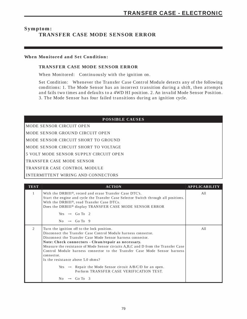
Symptom:TRANSFER CASE MODE SENSOR ERROR
When Monitored and Set Condition:
TRANSFER CASE MODE SENSOR ERROR
When Monitored: Continuously with the ignition on.
Set Condition: Whenever the Transfer Case Control Module detects any of the followingconditions: 1. The Mode Sensor has an incorrect transition during a shift, then attemptsand fails two times and defaults to a 4WD HI position. 2. An invalid Mode Sensor Position.3. The Mode Sensor has four failed transitions during an ignition cycle.
POSSIBLE CAUSES
MODE SENSOR CIRCUIT OPEN
MODE SENSOR GROUND CIRCUIT OPEN
MODE SENSOR CIRCUIT SHORT TO GROUND
MODE SENSOR CIRCUIT SHORT TO VOLTAGE
5 VOLT MODE SENSOR SUPPLY CIRCUIT OPEN
TRANSFER CASE MODE SENSOR
TRANSFER CASE CONTROL MODULE
INTERMITTENT WIRING AND CONNECTORS
TEST ACTION APPLICABILITY
1 With the DRBIIIt, record and erase Transfer Case DTC’s.Start the engine and cycle the Transfer Case Selector Switch through all positions.With the DRBIIIt, read Transfer Case DTCs.Does the DRBIIIt display TRANSFER CASE MODE SENSOR ERROR
All
Yes → Go To 2
No → Go To 9
2 Turn the ignition off to the lock position.Disconnect the Transfer Case Control Module harness connector.Disconnect the Transfer Case Mode Sensor harness connector.Note: Check connectors - Clean/repair as necessary.Measure the resistance of Mode Sensor circuits A,B,C and D from the Transfer CaseControl Module harness connector to the Transfer Case Mode Sensor harnessconnector.Is the resistance above 5.0 ohms?
All
Yes → Repair the Mode Sensor circuit A/B/C/D for an open.Perform TRANSFER CASE VERIFICATION TEST.
No → Go To 3
79
TRANSFER CASE - ELECTRONIC
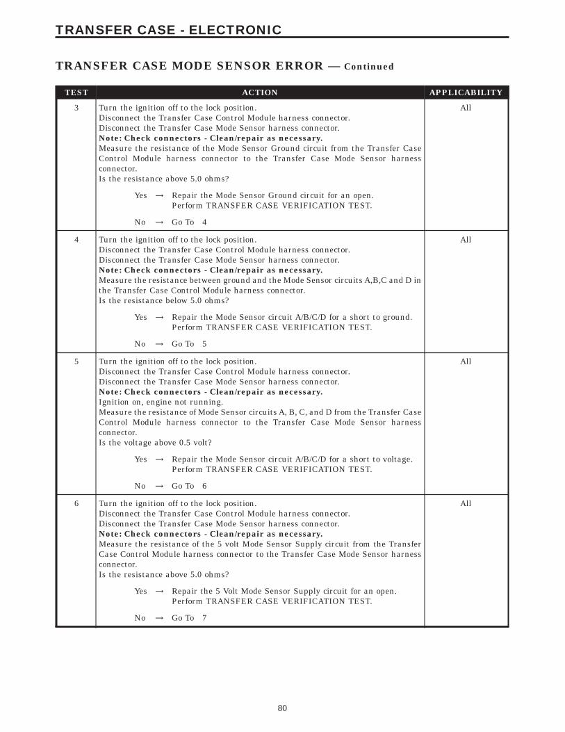
TEST ACTION APPLICABILITY
3 Turn the ignition off to the lock position.Disconnect the Transfer Case Control Module harness connector.Disconnect the Transfer Case Mode Sensor harness connector.Note: Check connectors - Clean/repair as necessary.Measure the resistance of the Mode Sensor Ground circuit from the Transfer CaseControl Module harness connector to the Transfer Case Mode Sensor harnessconnector.Is the resistance above 5.0 ohms?
All
Yes → Repair the Mode Sensor Ground circuit for an open.Perform TRANSFER CASE VERIFICATION TEST.
No → Go To 4
4 Turn the ignition off to the lock position.Disconnect the Transfer Case Control Module harness connector.Disconnect the Transfer Case Mode Sensor harness connector.Note: Check connectors - Clean/repair as necessary.Measure the resistance between ground and the Mode Sensor circuits A,B,C and D inthe Transfer Case Control Module harness connector.Is the resistance below 5.0 ohms?
All
Yes → Repair the Mode Sensor circuit A/B/C/D for a short to ground.Perform TRANSFER CASE VERIFICATION TEST.
No → Go To 5
5 Turn the ignition off to the lock position.Disconnect the Transfer Case Control Module harness connector.Disconnect the Transfer Case Mode Sensor harness connector.Note: Check connectors - Clean/repair as necessary.Ignition on, engine not running.Measure the resistance of Mode Sensor circuits A, B, C, and D from the Transfer CaseControl Module harness connector to the Transfer Case Mode Sensor harnessconnector.Is the voltage above 0.5 volt?
All
Yes → Repair the Mode Sensor circuit A/B/C/D for a short to voltage.Perform TRANSFER CASE VERIFICATION TEST.
No → Go To 6
6 Turn the ignition off to the lock position.Disconnect the Transfer Case Control Module harness connector.Disconnect the Transfer Case Mode Sensor harness connector.Note: Check connectors - Clean/repair as necessary.Measure the resistance of the 5 volt Mode Sensor Supply circuit from the TransferCase Control Module harness connector to the Transfer Case Mode Sensor harnessconnector.Is the resistance above 5.0 ohms?
All
Yes → Repair the 5 Volt Mode Sensor Supply circuit for an open.Perform TRANSFER CASE VERIFICATION TEST.
No → Go To 7
80
TRANSFER CASE - ELECTRONIC
TRANSFER CASE MODE SENSOR ERROR — Continued
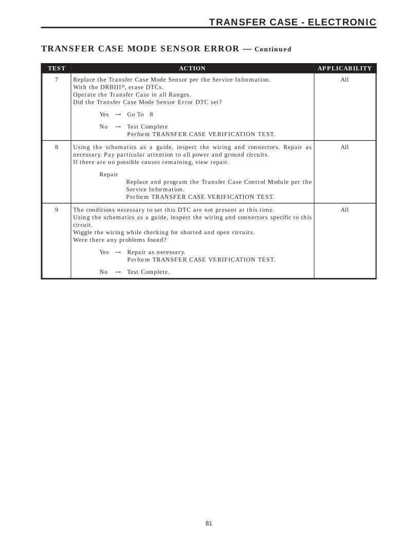
TEST ACTION APPLICABILITY
7 Replace the Transfer Case Mode Sensor per the Service Information.With the DRBIIIt, erase DTCs.Operate the Transfer Case in all Ranges.Did the Transfer Case Mode Sensor Error DTC set?
All
Yes → Go To 8
No → Test CompletePerform TRANSFER CASE VERIFICATION TEST.
8 Using the schematics as a guide, inspect the wiring and connectors. Repair asnecessary. Pay particular attention to all power and ground circuits.If there are no possible causes remaining, view repair.
All
RepairReplace and program the Transfer Case Control Module per theService Information.Perform TRANSFER CASE VERIFICATION TEST.
9 The conditions necessary to set this DTC are not present at this time.Using the schematics as a guide, inspect the wiring and connectors specific to thiscircuit.Wiggle the wiring while checking for shorted and open circuits.Were there any problems found?
All
Yes → Repair as necessary.Perform TRANSFER CASE VERIFICATION TEST.
No → Test Complete.
81
TRANSFER CASE - ELECTRONIC
TRANSFER CASE MODE SENSOR ERROR — Continued
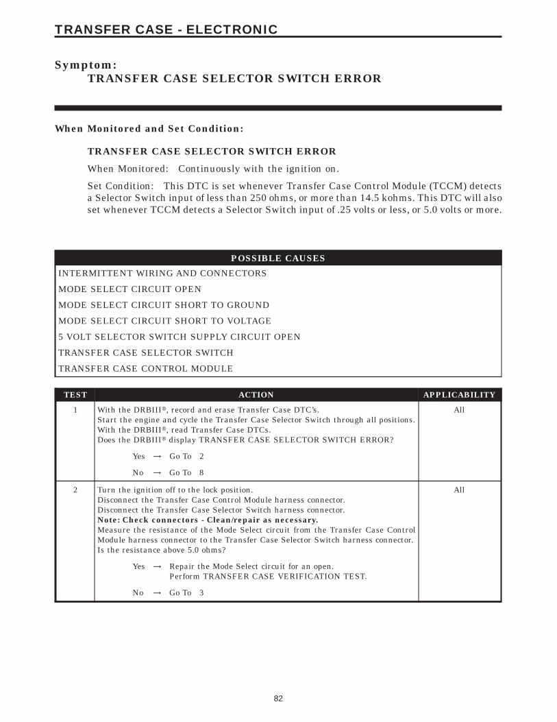
Symptom:TRANSFER CASE SELECTOR SWITCH ERROR
When Monitored and Set Condition:
TRANSFER CASE SELECTOR SWITCH ERROR
When Monitored: Continuously with the ignition on.
Set Condition: This DTC is set whenever Transfer Case Control Module (TCCM) detectsa Selector Switch input of less than 250 ohms, or more than 14.5 kohms. This DTC will alsoset whenever TCCM detects a Selector Switch input of .25 volts or less, or 5.0 volts or more.
POSSIBLE CAUSES
INTERMITTENT WIRING AND CONNECTORS
MODE SELECT CIRCUIT OPEN
MODE SELECT CIRCUIT SHORT TO GROUND
MODE SELECT CIRCUIT SHORT TO VOLTAGE
5 VOLT SELECTOR SWITCH SUPPLY CIRCUIT OPEN
TRANSFER CASE SELECTOR SWITCH
TRANSFER CASE CONTROL MODULE
TEST ACTION APPLICABILITY
1 With the DRBIIIt, record and erase Transfer Case DTC’s.Start the engine and cycle the Transfer Case Selector Switch through all positions.With the DRBIIIt, read Transfer Case DTCs.Does the DRBIIIt display TRANSFER CASE SELECTOR SWITCH ERROR?
All
Yes → Go To 2
No → Go To 8
2 Turn the ignition off to the lock position.Disconnect the Transfer Case Control Module harness connector.Disconnect the Transfer Case Selector Switch harness connector.Note: Check connectors - Clean/repair as necessary.Measure the resistance of the Mode Select circuit from the Transfer Case ControlModule harness connector to the Transfer Case Selector Switch harness connector.Is the resistance above 5.0 ohms?
All
Yes → Repair the Mode Select circuit for an open.Perform TRANSFER CASE VERIFICATION TEST.
No → Go To 3
82
TRANSFER CASE - ELECTRONIC
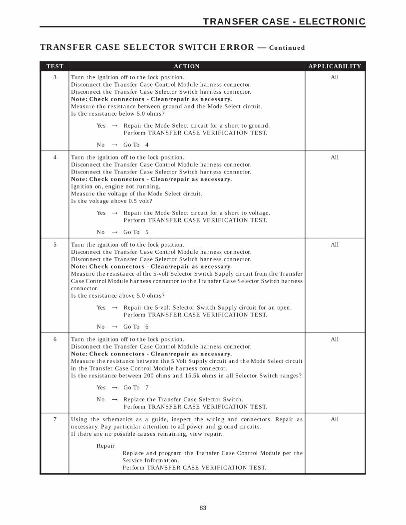
TEST ACTION APPLICABILITY
3 Turn the ignition off to the lock position.Disconnect the Transfer Case Control Module harness connector.Disconnect the Transfer Case Selector Switch harness connector.Note: Check connectors - Clean/repair as necessary.Measure the resistance between ground and the Mode Select circuit.Is the resistance below 5.0 ohms?
All
Yes → Repair the Mode Select circuit for a short to ground.Perform TRANSFER CASE VERIFICATION TEST.
No → Go To 4
4 Turn the ignition off to the lock position.Disconnect the Transfer Case Control Module harness connector.Disconnect the Transfer Case Selector Switch harness connector.Note: Check connectors - Clean/repair as necessary.Ignition on, engine not running.Measure the voltage of the Mode Select circuit.Is the voltage above 0.5 volt?
All
Yes → Repair the Mode Select circuit for a short to voltage.Perform TRANSFER CASE VERIFICATION TEST.
No → Go To 5
5 Turn the ignition off to the lock position.Disconnect the Transfer Case Control Module harness connector.Disconnect the Transfer Case Selector Switch harness connector.Note: Check connectors - Clean/repair as necessary.Measure the resistance of the 5-volt Selector Switch Supply circuit from the TransferCase Control Module harness connector to the Transfer Case Selector Switch harnessconnector.Is the resistance above 5.0 ohms?
All
Yes → Repair the 5-volt Selector Switch Supply circuit for an open.Perform TRANSFER CASE VERIFICATION TEST.
No → Go To 6
6 Turn the ignition off to the lock position.Disconnect the Transfer Case Control Module harness connector.Note: Check connectors - Clean/repair as necessary.Measure the resistance between the 5 Volt Supply circuit and the Mode Select circuitin the Transfer Case Control Module harness connector.Is the resistance between 200 ohms and 15.5k ohms in all Selector Switch ranges?
All
Yes → Go To 7
No → Replace the Transfer Case Selector Switch.Perform TRANSFER CASE VERIFICATION TEST.
7 Using the schematics as a guide, inspect the wiring and connectors. Repair asnecessary. Pay particular attention to all power and ground circuits.If there are no possible causes remaining, view repair.
All
RepairReplace and program the Transfer Case Control Module per theService Information.Perform TRANSFER CASE VERIFICATION TEST.
83
TRANSFER CASE - ELECTRONIC
TRANSFER CASE SELECTOR SWITCH ERROR — Continued
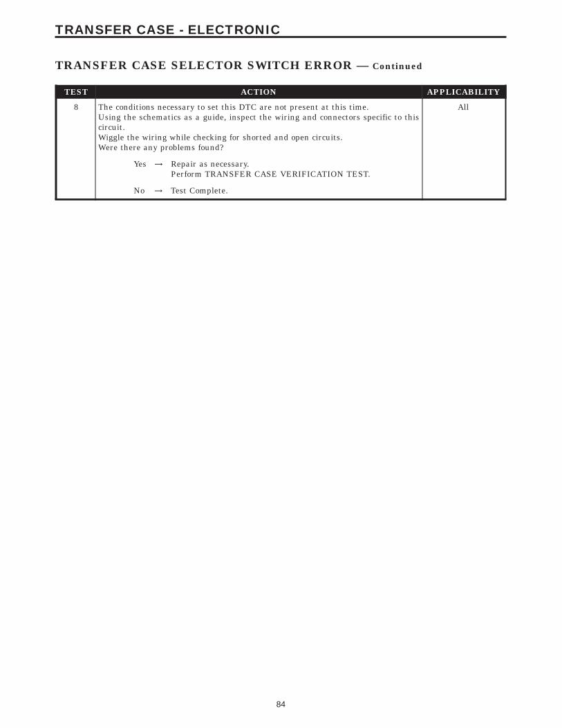
TEST ACTION APPLICABILITY
8 The conditions necessary to set this DTC are not present at this time.Using the schematics as a guide, inspect the wiring and connectors specific to thiscircuit.Wiggle the wiring while checking for shorted and open circuits.Were there any problems found?
All
Yes → Repair as necessary.Perform TRANSFER CASE VERIFICATION TEST.
No → Test Complete.
84
TRANSFER CASE - ELECTRONIC
TRANSFER CASE SELECTOR SWITCH ERROR — Continued
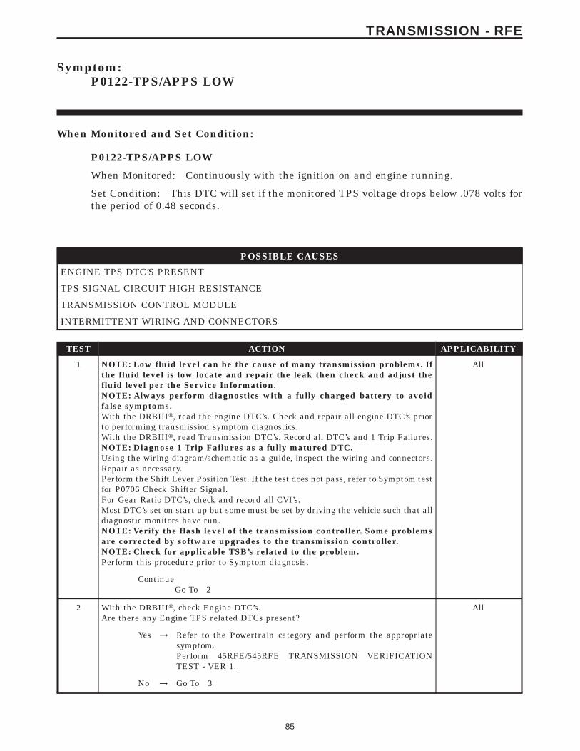
Symptom:P0122-TPS/APPS LOW
When Monitored and Set Condition:
P0122-TPS/APPS LOW
When Monitored: Continuously with the ignition on and engine running.
Set Condition: This DTC will set if the monitored TPS voltage drops below .078 volts forthe period of 0.48 seconds.
POSSIBLE CAUSES
ENGINE TPS DTC’S PRESENT
TPS SIGNAL CIRCUIT HIGH RESISTANCE
TRANSMISSION CONTROL MODULE
INTERMITTENT WIRING AND CONNECTORS
TEST ACTION APPLICABILITY
1 NOTE: Low fluid level can be the cause of many transmission problems. Ifthe fluid level is low locate and repair the leak then check and adjust thefluid level per the Service Information.NOTE: Always perform diagnostics with a fully charged battery to avoidfalse symptoms.With the DRBIIIt, read the engine DTC’s. Check and repair all engine DTC’s priorto performing transmission symptom diagnostics.With the DRBIIIt, read Transmission DTC’s. Record all DTC’s and 1 Trip Failures.NOTE: Diagnose 1 Trip Failures as a fully matured DTC.Using the wiring diagram/schematic as a guide, inspect the wiring and connectors.Repair as necessary.Perform the Shift Lever Position Test. If the test does not pass, refer to Symptom testfor P0706 Check Shifter Signal.For Gear Ratio DTC’s, check and record all CVI’s.Most DTC’s set on start up but some must be set by driving the vehicle such that alldiagnostic monitors have run.NOTE: Verify the flash level of the transmission controller. Some problemsare corrected by software upgrades to the transmission controller.NOTE: Check for applicable TSB’s related to the problem.Perform this procedure prior to Symptom diagnosis.
All
ContinueGo To 2
2 With the DRBIIIt, check Engine DTC’s.Are there any Engine TPS related DTCs present?
All
Yes → Refer to the Powertrain category and perform the appropriatesymptom.Perform 45RFE/545RFE TRANSMISSION VERIFICATIONTEST - VER 1.
No → Go To 3
85
TRANSMISSION - RFE
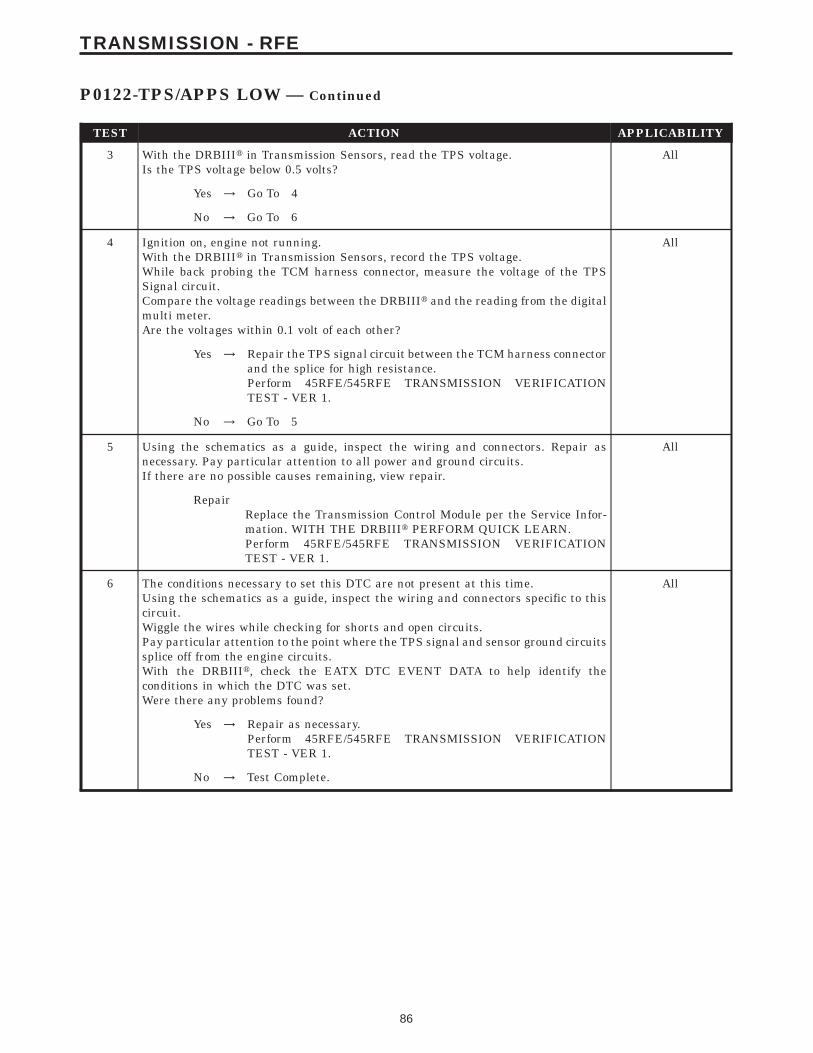
TEST ACTION APPLICABILITY
3 With the DRBIIIt in Transmission Sensors, read the TPS voltage.Is the TPS voltage below 0.5 volts?
All
Yes → Go To 4
No → Go To 6
4 Ignition on, engine not running.With the DRBIIIt in Transmission Sensors, record the TPS voltage.While back probing the TCM harness connector, measure the voltage of the TPSSignal circuit.Compare the voltage readings between the DRBIIIt and the reading from the digitalmulti meter.Are the voltages within 0.1 volt of each other?
All
Yes → Repair the TPS signal circuit between the TCM harness connectorand the splice for high resistance.Perform 45RFE/545RFE TRANSMISSION VERIFICATIONTEST - VER 1.
No → Go To 5
5 Using the schematics as a guide, inspect the wiring and connectors. Repair asnecessary. Pay particular attention to all power and ground circuits.If there are no possible causes remaining, view repair.
All
RepairReplace the Transmission Control Module per the Service Infor-mation. WITH THE DRBIIIt PERFORM QUICK LEARN.Perform 45RFE/545RFE TRANSMISSION VERIFICATIONTEST - VER 1.
6 The conditions necessary to set this DTC are not present at this time.Using the schematics as a guide, inspect the wiring and connectors specific to thiscircuit.Wiggle the wires while checking for shorts and open circuits.Pay particular attention to the point where the TPS signal and sensor ground circuitssplice off from the engine circuits.With the DRBIIIt, check the EATX DTC EVENT DATA to help identify theconditions in which the DTC was set.Were there any problems found?
All
Yes → Repair as necessary.Perform 45RFE/545RFE TRANSMISSION VERIFICATIONTEST - VER 1.
No → Test Complete.
86
TRANSMISSION - RFE
P0122-TPS/APPS LOW — Continued
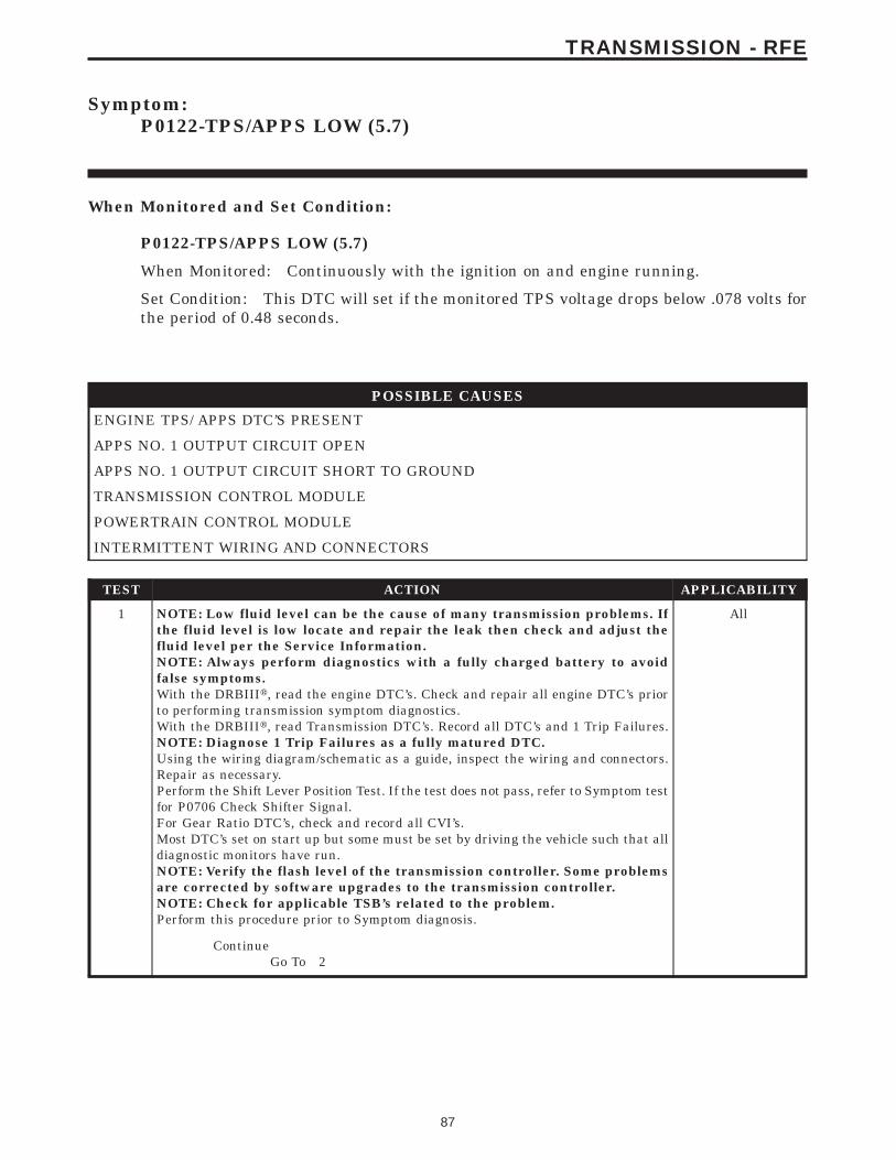
Symptom:P0122-TPS/APPS LOW (5.7)
When Monitored and Set Condition:
P0122-TPS/APPS LOW (5.7)
When Monitored: Continuously with the ignition on and engine running.
Set Condition: This DTC will set if the monitored TPS voltage drops below .078 volts forthe period of 0.48 seconds.
POSSIBLE CAUSES
ENGINE TPS/ APPS DTC’S PRESENT
APPS NO. 1 OUTPUT CIRCUIT OPEN
APPS NO. 1 OUTPUT CIRCUIT SHORT TO GROUND
TRANSMISSION CONTROL MODULE
POWERTRAIN CONTROL MODULE
INTERMITTENT WIRING AND CONNECTORS
TEST ACTION APPLICABILITY
1 NOTE: Low fluid level can be the cause of many transmission problems. Ifthe fluid level is low locate and repair the leak then check and adjust thefluid level per the Service Information.NOTE: Always perform diagnostics with a fully charged battery to avoidfalse symptoms.With the DRBIIIt, read the engine DTC’s. Check and repair all engine DTC’s priorto performing transmission symptom diagnostics.With the DRBIIIt, read Transmission DTC’s. Record all DTC’s and 1 Trip Failures.NOTE: Diagnose 1 Trip Failures as a fully matured DTC.Using the wiring diagram/schematic as a guide, inspect the wiring and connectors.Repair as necessary.Perform the Shift Lever Position Test. If the test does not pass, refer to Symptom testfor P0706 Check Shifter Signal.For Gear Ratio DTC’s, check and record all CVI’s.Most DTC’s set on start up but some must be set by driving the vehicle such that alldiagnostic monitors have run.NOTE: Verify the flash level of the transmission controller. Some problemsare corrected by software upgrades to the transmission controller.NOTE: Check for applicable TSB’s related to the problem.Perform this procedure prior to Symptom diagnosis.
All
ContinueGo To 2
87
TRANSMISSION - RFE
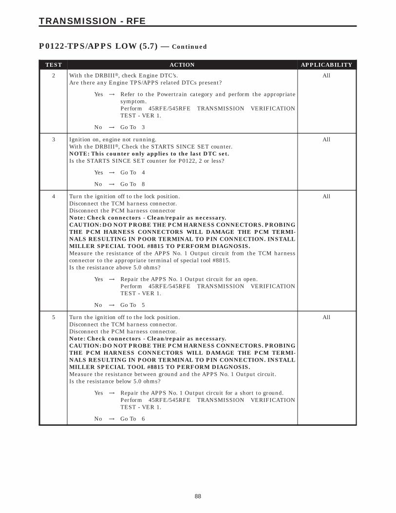
TEST ACTION APPLICABILITY
2 With the DRBIIIt, check Engine DTC’s.Are there any Engine TPS/APPS related DTCs present?
All
Yes → Refer to the Powertrain category and perform the appropriatesymptom.Perform 45RFE/545RFE TRANSMISSION VERIFICATIONTEST - VER 1.
No → Go To 3
3 Ignition on, engine not running.With the DRBIIIt, Check the STARTS SINCE SET counter.NOTE: This counter only applies to the last DTC set.Is the STARTS SINCE SET counter for P0122, 2 or less?
All
Yes → Go To 4
No → Go To 8
4 Turn the ignition off to the lock position.Disconnect the TCM harness connector.Disconnect the PCM harness connectorNote: Check connectors - Clean/repair as necessary.CAUTION: DO NOT PROBE THE PCM HARNESS CONNECTORS. PROBINGTHE PCM HARNESS CONNECTORS WILL DAMAGE THE PCM TERMI-NALS RESULTING IN POOR TERMINAL TO PIN CONNECTION. INSTALLMILLER SPECIAL TOOL #8815 TO PERFORM DIAGNOSIS.Measure the resistance of the APPS No. 1 Output circuit from the TCM harnessconnector to the appropriate terminal of special tool #8815.Is the resistance above 5.0 ohms?
All
Yes → Repair the APPS No. 1 Output circuit for an open.Perform 45RFE/545RFE TRANSMISSION VERIFICATIONTEST - VER 1.
No → Go To 5
5 Turn the ignition off to the lock position.Disconnect the TCM harness connector.Disconnect the PCM harness connector.Note: Check connectors - Clean/repair as necessary.CAUTION: DO NOT PROBE THE PCM HARNESS CONNECTORS. PROBINGTHE PCM HARNESS CONNECTORS WILL DAMAGE THE PCM TERMI-NALS RESULTING IN POOR TERMINAL TO PIN CONNECTION. INSTALLMILLER SPECIAL TOOL #8815 TO PERFORM DIAGNOSIS.Measure the resistance between ground and the APPS No. 1 Output circuit.Is the resistance below 5.0 ohms?
All
Yes → Repair the APPS No. 1 Output circuit for a short to ground.Perform 45RFE/545RFE TRANSMISSION VERIFICATIONTEST - VER 1.
No → Go To 6
88
TRANSMISSION - RFE
P0122-TPS/APPS LOW (5.7) — Continued
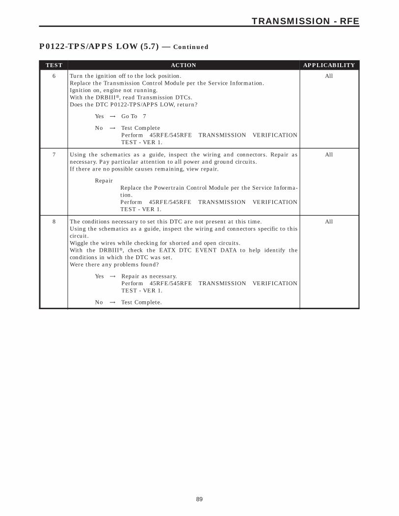
TEST ACTION APPLICABILITY
6 Turn the ignition off to the lock position.Replace the Transmission Control Module per the Service Information.Ignition on, engine not running.With the DRBIIIt, read Transmission DTCs.Does the DTC P0122-TPS/APPS LOW, return?
All
Yes → Go To 7
No → Test CompletePerform 45RFE/545RFE TRANSMISSION VERIFICATIONTEST - VER 1.
7 Using the schematics as a guide, inspect the wiring and connectors. Repair asnecessary. Pay particular attention to all power and ground circuits.If there are no possible causes remaining, view repair.
All
RepairReplace the Powertrain Control Module per the Service Informa-tion.Perform 45RFE/545RFE TRANSMISSION VERIFICATIONTEST - VER 1.
8 The conditions necessary to set this DTC are not present at this time.Using the schematics as a guide, inspect the wiring and connectors specific to thiscircuit.Wiggle the wires while checking for shorted and open circuits.With the DRBIIIt, check the EATX DTC EVENT DATA to help identify theconditions in which the DTC was set.Were there any problems found?
All
Yes → Repair as necessary.Perform 45RFE/545RFE TRANSMISSION VERIFICATIONTEST - VER 1.
No → Test Complete.
89
TRANSMISSION - RFE
P0122-TPS/APPS LOW (5.7) — Continued
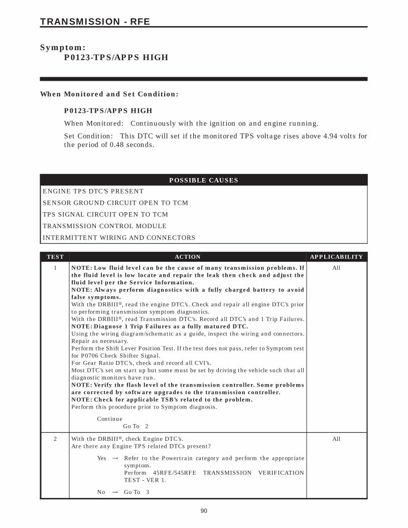
Symptom:P0123-TPS/APPS HIGH
When Monitored and Set Condition:
P0123-TPS/APPS HIGH
When Monitored: Continuously with the ignition on and engine running.
Set Condition: This DTC will set if the monitored TPS voltage rises above 4.94 volts forthe period of 0.48 seconds.
POSSIBLE CAUSES
ENGINE TPS DTC’S PRESENT
SENSOR GROUND CIRCUIT OPEN TO TCM
TPS SIGNAL CIRCUIT OPEN TO TCM
TRANSMISSION CONTROL MODULE
INTERMITTENT WIRING AND CONNECTORS
TEST ACTION APPLICABILITY
1 NOTE: Low fluid level can be the cause of many transmission problems. Ifthe fluid level is low locate and repair the leak then check and adjust thefluid level per the Service Information.NOTE: Always perform diagnostics with a fully charged battery to avoidfalse symptoms.With the DRBIIIt, read the engine DTC’s. Check and repair all engine DTC’s priorto performing transmission symptom diagnostics.With the DRBIIIt, read Transmission DTC’s. Record all DTC’s and 1 Trip Failures.NOTE: Diagnose 1 Trip Failures as a fully matured DTC.Using the wiring diagram/schematic as a guide, inspect the wiring and connectors.Repair as necessary.Perform the Shift Lever Position Test. If the test does not pass, refer to Symptom testfor P0706 Check Shifter Signal.For Gear Ratio DTC’s, check and record all CVI’s.Most DTC’s set on start up but some must be set by driving the vehicle such that alldiagnostic monitors have run.NOTE: Verify the flash level of the transmission controller. Some problemsare corrected by software upgrades to the transmission controller.NOTE: Check for applicable TSB’s related to the problem.Perform this procedure prior to Symptom diagnosis.
All
ContinueGo To 2
2 With the DRBIIIt, check Engine DTC’s.Are there any Engine TPS related DTCs present?
All
Yes → Refer to the Powertrain category and perform the appropriatesymptom.Perform 45RFE/545RFE TRANSMISSION VERIFICATIONTEST - VER 1.
No → Go To 3
90
TRANSMISSION - RFE
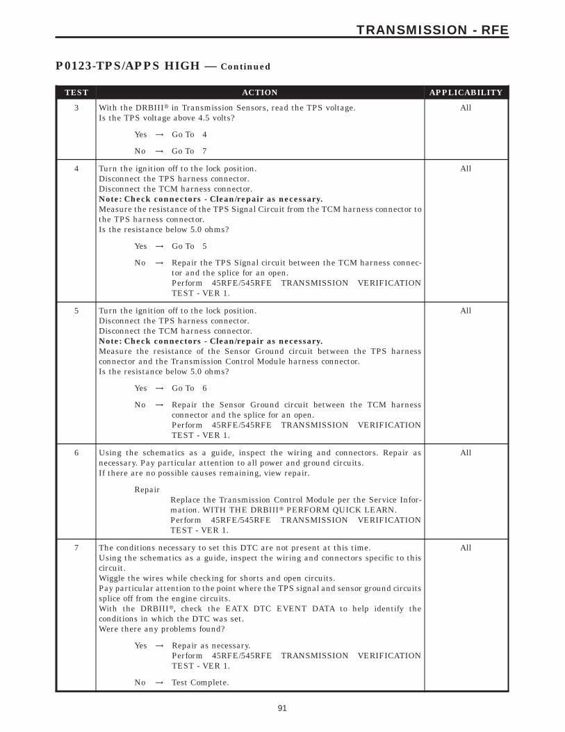
TEST ACTION APPLICABILITY
3 With the DRBIIIt in Transmission Sensors, read the TPS voltage.Is the TPS voltage above 4.5 volts?
All
Yes → Go To 4
No → Go To 7
4 Turn the ignition off to the lock position.Disconnect the TPS harness connector.Disconnect the TCM harness connector.Note: Check connectors - Clean/repair as necessary.Measure the resistance of the TPS Signal Circuit from the TCM harness connector tothe TPS harness connector.Is the resistance below 5.0 ohms?
All
Yes → Go To 5
No → Repair the TPS Signal circuit between the TCM harness connec-tor and the splice for an open.Perform 45RFE/545RFE TRANSMISSION VERIFICATIONTEST - VER 1.
5 Turn the ignition off to the lock position.Disconnect the TPS harness connector.Disconnect the TCM harness connector.Note: Check connectors - Clean/repair as necessary.Measure the resistance of the Sensor Ground circuit between the TPS harnessconnector and the Transmission Control Module harness connector.Is the resistance below 5.0 ohms?
All
Yes → Go To 6
No → Repair the Sensor Ground circuit between the TCM harnessconnector and the splice for an open.Perform 45RFE/545RFE TRANSMISSION VERIFICATIONTEST - VER 1.
6 Using the schematics as a guide, inspect the wiring and connectors. Repair asnecessary. Pay particular attention to all power and ground circuits.If there are no possible causes remaining, view repair.
All
RepairReplace the Transmission Control Module per the Service Infor-mation. WITH THE DRBIIIt PERFORM QUICK LEARN.Perform 45RFE/545RFE TRANSMISSION VERIFICATIONTEST - VER 1.
7 The conditions necessary to set this DTC are not present at this time.Using the schematics as a guide, inspect the wiring and connectors specific to thiscircuit.Wiggle the wires while checking for shorts and open circuits.Pay particular attention to the point where the TPS signal and sensor ground circuitssplice off from the engine circuits.With the DRBIIIt, check the EATX DTC EVENT DATA to help identify theconditions in which the DTC was set.Were there any problems found?
All
Yes → Repair as necessary.Perform 45RFE/545RFE TRANSMISSION VERIFICATIONTEST - VER 1.
No → Test Complete.
91
TRANSMISSION - RFE
P0123-TPS/APPS HIGH — Continued
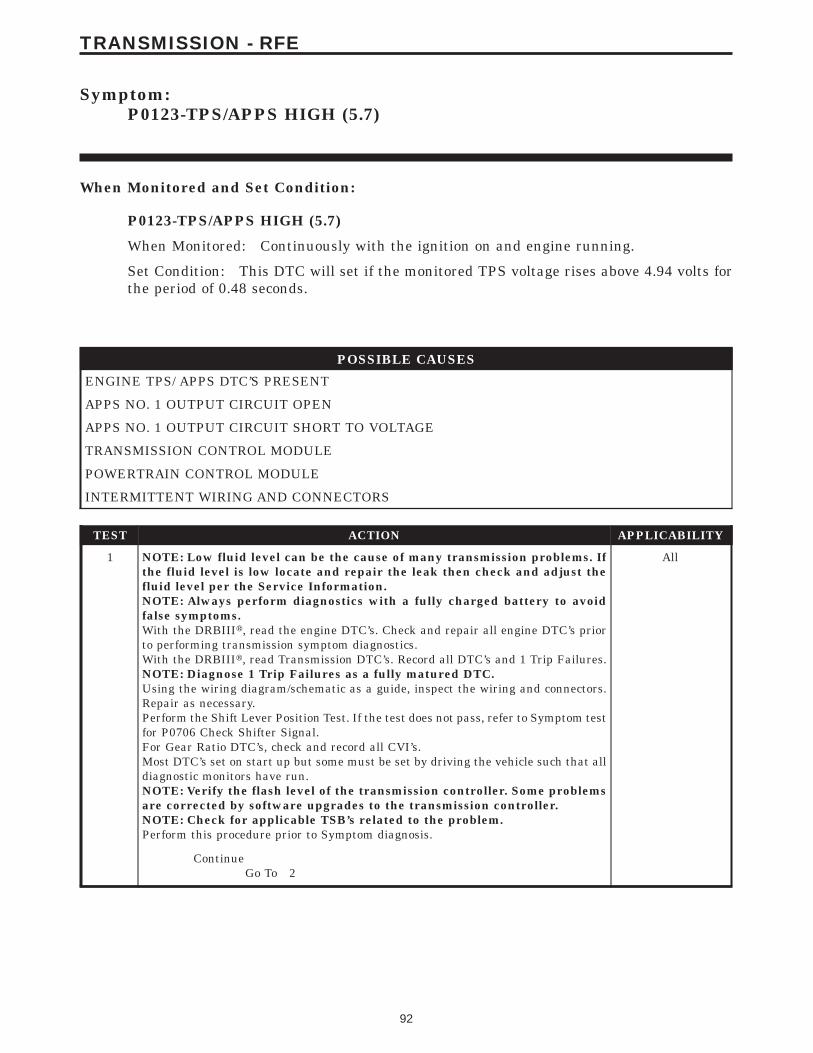
Symptom:P0123-TPS/APPS HIGH (5.7)
When Monitored and Set Condition:
P0123-TPS/APPS HIGH (5.7)
When Monitored: Continuously with the ignition on and engine running.
Set Condition: This DTC will set if the monitored TPS voltage rises above 4.94 volts forthe period of 0.48 seconds.
POSSIBLE CAUSES
ENGINE TPS/ APPS DTC’S PRESENT
APPS NO. 1 OUTPUT CIRCUIT OPEN
APPS NO. 1 OUTPUT CIRCUIT SHORT TO VOLTAGE
TRANSMISSION CONTROL MODULE
POWERTRAIN CONTROL MODULE
INTERMITTENT WIRING AND CONNECTORS
TEST ACTION APPLICABILITY
1 NOTE: Low fluid level can be the cause of many transmission problems. Ifthe fluid level is low locate and repair the leak then check and adjust thefluid level per the Service Information.NOTE: Always perform diagnostics with a fully charged battery to avoidfalse symptoms.With the DRBIIIt, read the engine DTC’s. Check and repair all engine DTC’s priorto performing transmission symptom diagnostics.With the DRBIIIt, read Transmission DTC’s. Record all DTC’s and 1 Trip Failures.NOTE: Diagnose 1 Trip Failures as a fully matured DTC.Using the wiring diagram/schematic as a guide, inspect the wiring and connectors.Repair as necessary.Perform the Shift Lever Position Test. If the test does not pass, refer to Symptom testfor P0706 Check Shifter Signal.For Gear Ratio DTC’s, check and record all CVI’s.Most DTC’s set on start up but some must be set by driving the vehicle such that alldiagnostic monitors have run.NOTE: Verify the flash level of the transmission controller. Some problemsare corrected by software upgrades to the transmission controller.NOTE: Check for applicable TSB’s related to the problem.Perform this procedure prior to Symptom diagnosis.
All
ContinueGo To 2
92
TRANSMISSION - RFE
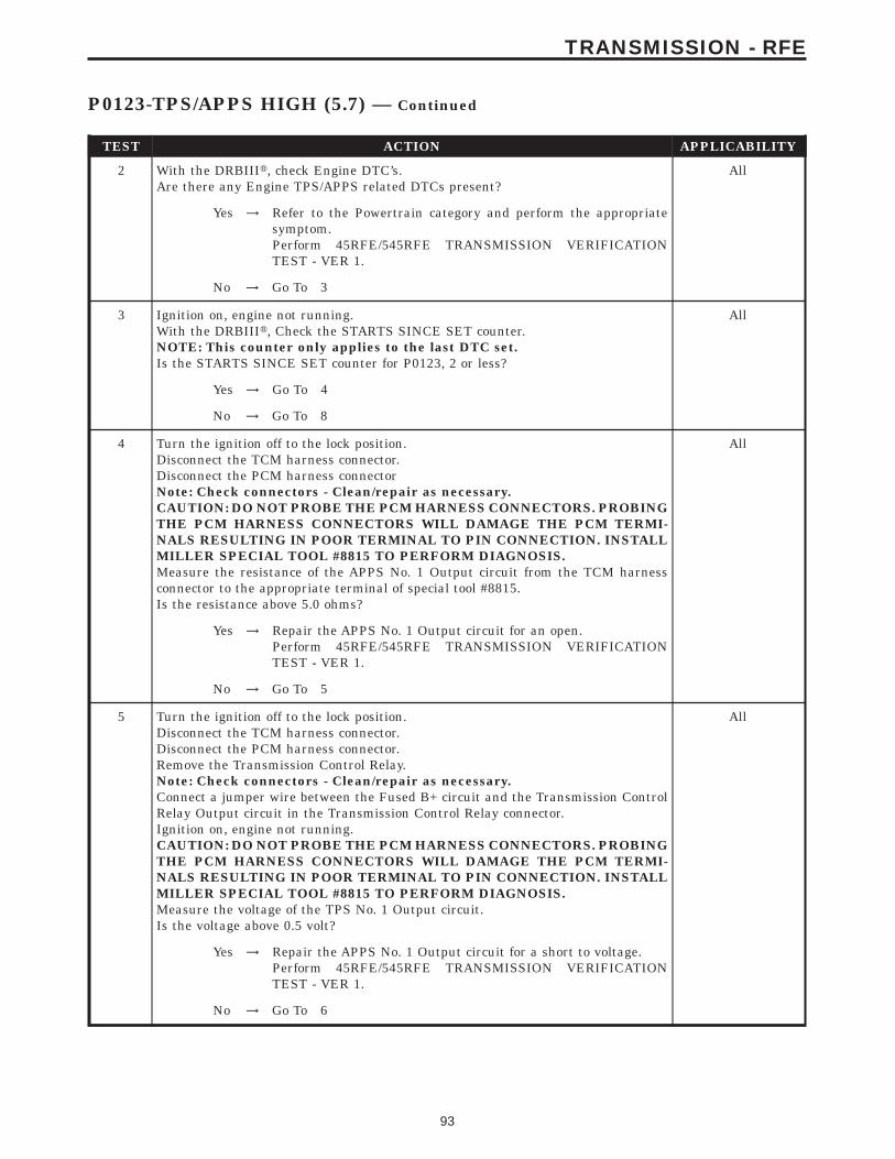
TEST ACTION APPLICABILITY
2 With the DRBIIIt, check Engine DTC’s.Are there any Engine TPS/APPS related DTCs present?
All
Yes → Refer to the Powertrain category and perform the appropriatesymptom.Perform 45RFE/545RFE TRANSMISSION VERIFICATIONTEST - VER 1.
No → Go To 3
3 Ignition on, engine not running.With the DRBIIIt, Check the STARTS SINCE SET counter.NOTE: This counter only applies to the last DTC set.Is the STARTS SINCE SET counter for P0123, 2 or less?
All
Yes → Go To 4
No → Go To 8
4 Turn the ignition off to the lock position.Disconnect the TCM harness connector.Disconnect the PCM harness connectorNote: Check connectors - Clean/repair as necessary.CAUTION: DO NOT PROBE THE PCM HARNESS CONNECTORS. PROBINGTHE PCM HARNESS CONNECTORS WILL DAMAGE THE PCM TERMI-NALS RESULTING IN POOR TERMINAL TO PIN CONNECTION. INSTALLMILLER SPECIAL TOOL #8815 TO PERFORM DIAGNOSIS.Measure the resistance of the APPS No. 1 Output circuit from the TCM harnessconnector to the appropriate terminal of special tool #8815.Is the resistance above 5.0 ohms?
All
Yes → Repair the APPS No. 1 Output circuit for an open.Perform 45RFE/545RFE TRANSMISSION VERIFICATIONTEST - VER 1.
No → Go To 5
5 Turn the ignition off to the lock position.Disconnect the TCM harness connector.Disconnect the PCM harness connector.Remove the Transmission Control Relay.Note: Check connectors - Clean/repair as necessary.Connect a jumper wire between the Fused B+ circuit and the Transmission ControlRelay Output circuit in the Transmission Control Relay connector.Ignition on, engine not running.CAUTION: DO NOT PROBE THE PCM HARNESS CONNECTORS. PROBINGTHE PCM HARNESS CONNECTORS WILL DAMAGE THE PCM TERMI-NALS RESULTING IN POOR TERMINAL TO PIN CONNECTION. INSTALLMILLER SPECIAL TOOL #8815 TO PERFORM DIAGNOSIS.Measure the voltage of the TPS No. 1 Output circuit.Is the voltage above 0.5 volt?
All
Yes → Repair the APPS No. 1 Output circuit for a short to voltage.Perform 45RFE/545RFE TRANSMISSION VERIFICATIONTEST - VER 1.
No → Go To 6
93
TRANSMISSION - RFE
P0123-TPS/APPS HIGH (5.7) — Continued
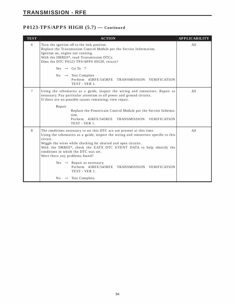
TEST ACTION APPLICABILITY
6 Turn the ignition off to the lock position.Replace the Transmission Control Module per the Service Information.Ignition on, engine not running.With the DRBIIIt, read Transmission DTCs.Does the DTC P0123 TPS/APPS HIGH, return?
All
Yes → Go To 7
No → Test CompletePerform 45RFE/545RFE TRANSMISSION VERIFICATIONTEST - VER 1.
7 Using the schematics as a guide, inspect the wiring and connectors. Repair asnecessary. Pay particular attention to all power and ground circuits.If there are no possible causes remaining, view repair.
All
RepairReplace the Powertrain Control Module per the Service Informa-tion.Perform 45RFE/545RFE TRANSMISSION VERIFICATIONTEST - VER 1.
8 The conditions necessary to set this DTC are not present at this time.Using the schematics as a guide, inspect the wiring and connectors specific to thiscircuit.Wiggle the wires while checking for shorted and open circuits.With the DRBIIIt, check the EATX DTC EVENT DATA to help identify theconditions in which the DTC was set.Were there any problems found?
All
Yes → Repair as necessary.Perform 45RFE/545RFE TRANSMISSION VERIFICATIONTEST - VER 1.
No → Test Complete.
94
TRANSMISSION - RFE
P0123-TPS/APPS HIGH (5.7) — Continued
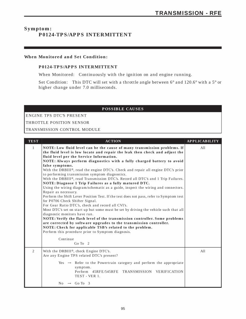
Symptom:P0124-TPS/APPS INTERMITTENT
When Monitored and Set Condition:
P0124-TPS/APPS INTERMITTENT
When Monitored: Continuously with the ignition on and engine running.
Set Condition: This DTC will set with a throttle angle between 6° and 120.6° with a 5° orhigher change under 7.0 milliseconds.
POSSIBLE CAUSES
ENGINE TPS DTC’S PRESENT
THROTTLE POSITION SENSOR
TRANSMISSION CONTROL MODULE
TEST ACTION APPLICABILITY
1 NOTE: Low fluid level can be the cause of many transmission problems. Ifthe fluid level is low locate and repair the leak then check and adjust thefluid level per the Service Information.NOTE: Always perform diagnostics with a fully charged battery to avoidfalse symptoms.With the DRBIIIt, read the engine DTC’s. Check and repair all engine DTC’s priorto performing transmission symptom diagnostics.With the DRBIIIt, read Transmission DTC’s. Record all DTC’s and 1 Trip Failures.NOTE: Diagnose 1 Trip Failures as a fully matured DTC.Using the wiring diagram/schematic as a guide, inspect the wiring and connectors.Repair as necessary.Perform the Shift Lever Position Test. If the test does not pass, refer to Symptom testfor P0706 Check Shifter Signal.For Gear Ratio DTC’s, check and record all CVI’s.Most DTC’s set on start up but some must be set by driving the vehicle such that alldiagnostic monitors have run.NOTE: Verify the flash level of the transmission controller. Some problemsare corrected by software upgrades to the transmission controller.NOTE: Check for applicable TSB’s related to the problem.Perform this procedure prior to Symptom diagnosis.
All
ContinueGo To 2
2 With the DRBIIIt, check Engine DTC’s.Are any Engine TPS related DTC’s present?
All
Yes → Refer to the Powertrain category and perform the appropriatesymptom.Perform 45RFE/545RFE TRANSMISSION VERIFICATIONTEST - VER 1.
No → Go To 3
95
TRANSMISSION - RFE
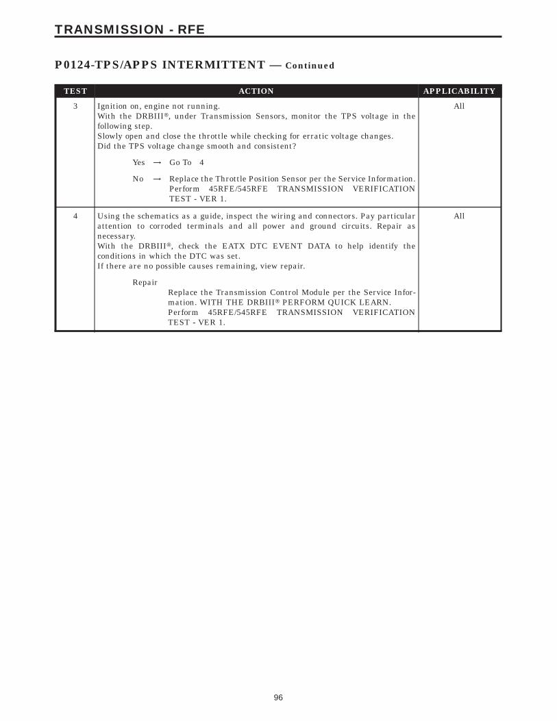
TEST ACTION APPLICABILITY
3 Ignition on, engine not running.With the DRBIIIt, under Transmission Sensors, monitor the TPS voltage in thefollowing step.Slowly open and close the throttle while checking for erratic voltage changes.Did the TPS voltage change smooth and consistent?
All
Yes → Go To 4
No → Replace the Throttle Position Sensor per the Service Information.Perform 45RFE/545RFE TRANSMISSION VERIFICATIONTEST - VER 1.
4 Using the schematics as a guide, inspect the wiring and connectors. Pay particularattention to corroded terminals and all power and ground circuits. Repair asnecessary.With the DRBIIIt, check the EATX DTC EVENT DATA to help identify theconditions in which the DTC was set.If there are no possible causes remaining, view repair.
All
RepairReplace the Transmission Control Module per the Service Infor-mation. WITH THE DRBIIIt PERFORM QUICK LEARN.Perform 45RFE/545RFE TRANSMISSION VERIFICATIONTEST - VER 1.
96
TRANSMISSION - RFE
P0124-TPS/APPS INTERMITTENT — Continued
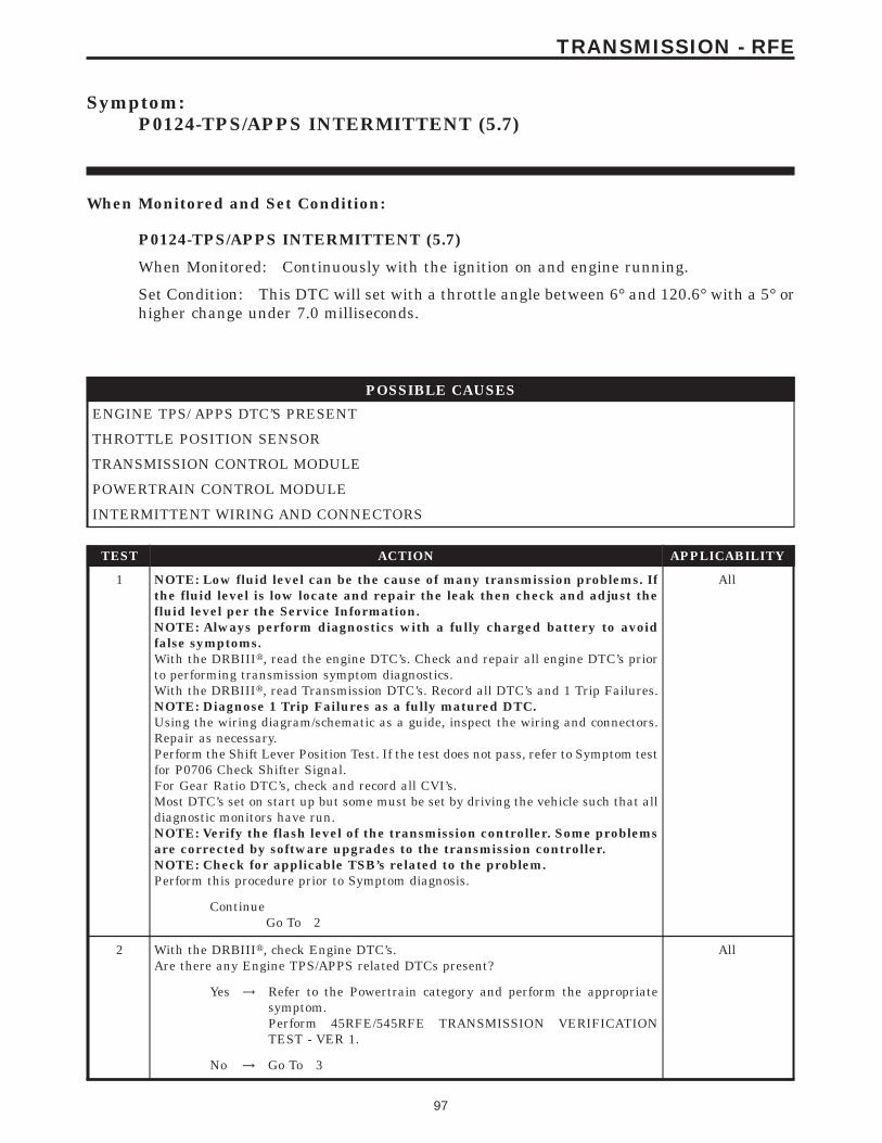
Symptom:P0124-TPS/APPS INTERMITTENT (5.7)
When Monitored and Set Condition:
P0124-TPS/APPS INTERMITTENT (5.7)
When Monitored: Continuously with the ignition on and engine running.
Set Condition: This DTC will set with a throttle angle between 6° and 120.6° with a 5° orhigher change under 7.0 milliseconds.
POSSIBLE CAUSES
ENGINE TPS/ APPS DTC’S PRESENT
THROTTLE POSITION SENSOR
TRANSMISSION CONTROL MODULE
POWERTRAIN CONTROL MODULE
INTERMITTENT WIRING AND CONNECTORS
TEST ACTION APPLICABILITY
1 NOTE: Low fluid level can be the cause of many transmission problems. Ifthe fluid level is low locate and repair the leak then check and adjust thefluid level per the Service Information.NOTE: Always perform diagnostics with a fully charged battery to avoidfalse symptoms.With the DRBIIIt, read the engine DTC’s. Check and repair all engine DTC’s priorto performing transmission symptom diagnostics.With the DRBIIIt, read Transmission DTC’s. Record all DTC’s and 1 Trip Failures.NOTE: Diagnose 1 Trip Failures as a fully matured DTC.Using the wiring diagram/schematic as a guide, inspect the wiring and connectors.Repair as necessary.Perform the Shift Lever Position Test. If the test does not pass, refer to Symptom testfor P0706 Check Shifter Signal.For Gear Ratio DTC’s, check and record all CVI’s.Most DTC’s set on start up but some must be set by driving the vehicle such that alldiagnostic monitors have run.NOTE: Verify the flash level of the transmission controller. Some problemsare corrected by software upgrades to the transmission controller.NOTE: Check for applicable TSB’s related to the problem.Perform this procedure prior to Symptom diagnosis.
All
ContinueGo To 2
2 With the DRBIIIt, check Engine DTC’s.Are there any Engine TPS/APPS related DTCs present?
All
Yes → Refer to the Powertrain category and perform the appropriatesymptom.Perform 45RFE/545RFE TRANSMISSION VERIFICATIONTEST - VER 1.
No → Go To 3
97
TRANSMISSION - RFE
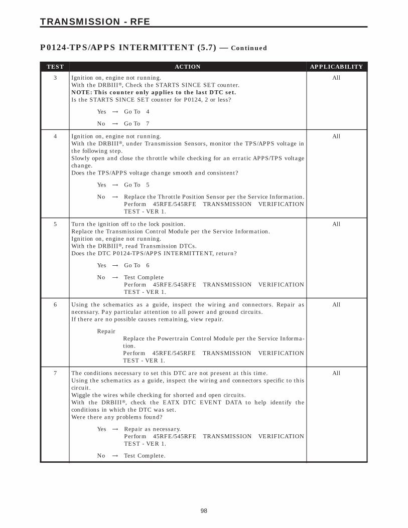
TEST ACTION APPLICABILITY
3 Ignition on, engine not running.With the DRBIIIt, Check the STARTS SINCE SET counter.NOTE: This counter only applies to the last DTC set.Is the STARTS SINCE SET counter for P0124, 2 or less?
All
Yes → Go To 4
No → Go To 7
4 Ignition on, engine not running.With the DRBIIIt, under Transmission Sensors, monitor the TPS/APPS voltage inthe following step.Slowly open and close the throttle while checking for an erratic APPS/TPS voltagechange.Does the TPS/APPS voltage change smooth and consistent?
All
Yes → Go To 5
No → Replace the Throttle Position Sensor per the Service Information.Perform 45RFE/545RFE TRANSMISSION VERIFICATIONTEST - VER 1.
5 Turn the ignition off to the lock position.Replace the Transmission Control Module per the Service Information.Ignition on, engine not running.With the DRBIIIt, read Transmission DTCs.Does the DTC P0124-TPS/APPS INTERMITTENT, return?
All
Yes → Go To 6
No → Test CompletePerform 45RFE/545RFE TRANSMISSION VERIFICATIONTEST - VER 1.
6 Using the schematics as a guide, inspect the wiring and connectors. Repair asnecessary. Pay particular attention to all power and ground circuits.If there are no possible causes remaining, view repair.
All
RepairReplace the Powertrain Control Module per the Service Informa-tion.Perform 45RFE/545RFE TRANSMISSION VERIFICATIONTEST - VER 1.
7 The conditions necessary to set this DTC are not present at this time.Using the schematics as a guide, inspect the wiring and connectors specific to thiscircuit.Wiggle the wires while checking for shorted and open circuits.With the DRBIIIt, check the EATX DTC EVENT DATA to help identify theconditions in which the DTC was set.Were there any problems found?
All
Yes → Repair as necessary.Perform 45RFE/545RFE TRANSMISSION VERIFICATIONTEST - VER 1.
No → Test Complete.
98
TRANSMISSION - RFE
P0124-TPS/APPS INTERMITTENT (5.7) — Continued
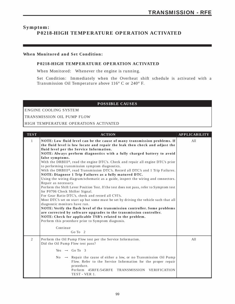
Symptom:P0218-HIGH TEMPERATURE OPERATION ACTIVATED
When Monitored and Set Condition:
P0218-HIGH TEMPERATURE OPERATION ACTIVATED
When Monitored: Whenever the engine is running.
Set Condition: Immediately when the Overheat shift schedule is activated with aTransmission Oil Temperature above 116° C or 240° F.
POSSIBLE CAUSES
ENGINE COOLING SYSTEM
TRANSMISSION OIL PUMP FLOW
HIGH TEMPERATURE OPERATIONS ACTIVATED
TEST ACTION APPLICABILITY
1 NOTE: Low fluid level can be the cause of many transmission problems. Ifthe fluid level is low locate and repair the leak then check and adjust thefluid level per the Service Information.NOTE: Always perform diagnostics with a fully charged battery to avoidfalse symptoms.With the DRBIIIt, read the engine DTC’s. Check and repair all engine DTC’s priorto performing transmission symptom diagnostics.With the DRBIIIt, read Transmission DTC’s. Record all DTC’s and 1 Trip Failures.NOTE: Diagnose 1 Trip Failures as a fully matured DTC.Using the wiring diagram/schematic as a guide, inspect the wiring and connectors.Repair as necessary.Perform the Shift Lever Position Test. If the test does not pass, refer to Symptom testfor P0706 Check Shifter Signal.For Gear Ratio DTC’s, check and record all CVI’s.Most DTC’s set on start up but some must be set by driving the vehicle such that alldiagnostic monitors have run.NOTE: Verify the flash level of the transmission controller. Some problemsare corrected by software upgrades to the transmission controller.NOTE: Check for applicable TSB’s related to the problem.Perform this procedure prior to Symptom diagnosis.
All
ContinueGo To 2
2 Perform the Oil Pump Flow test per the Service Information.Did the Oil Pump Flow test pass?
All
Yes → Go To 3
No → Repair the cause of either a low, or no Transmission Oil PumpFlow. Refer to the Service Information for the proper repairprocedure.Perform 45RFE/545RFE TRANSMISSION VERIFICATIONTEST - VER 1.
99
TRANSMISSION - RFE
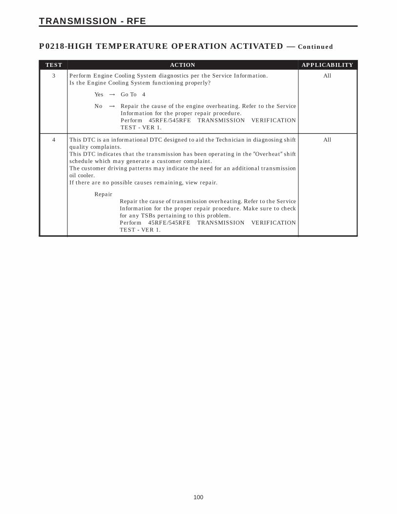
TEST ACTION APPLICABILITY
3 Perform Engine Cooling System diagnostics per the Service Information.Is the Engine Cooling System functioning properly?
All
Yes → Go To 4
No → Repair the cause of the engine overheating. Refer to the ServiceInformation for the proper repair procedure.Perform 45RFE/545RFE TRANSMISSION VERIFICATIONTEST - VER 1.
4 This DTC is an informational DTC designed to aid the Technician in diagnosing shiftquality complaints.This DTC indicates that the transmission has been operating in the 9Overheat9 shiftschedule which may generate a customer complaint.The customer driving patterns may indicate the need for an additional transmissionoil cooler.If there are no possible causes remaining, view repair.
All
RepairRepair the cause of transmission overheating. Refer to the ServiceInformation for the proper repair procedure. Make sure to checkfor any TSBs pertaining to this problem.Perform 45RFE/545RFE TRANSMISSION VERIFICATIONTEST - VER 1.
100
TRANSMISSION - RFE
P0218-HIGH TEMPERATURE OPERATION ACTIVATED — Continued
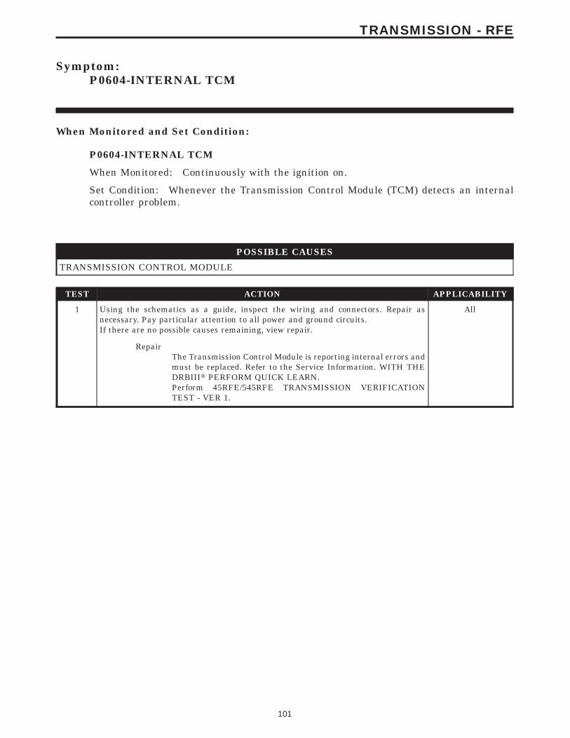
Symptom:P0604-INTERNAL TCM
When Monitored and Set Condition:
P0604-INTERNAL TCM
When Monitored: Continuously with the ignition on.
Set Condition: Whenever the Transmission Control Module (TCM) detects an internalcontroller problem.
POSSIBLE CAUSES
TRANSMISSION CONTROL MODULE
TEST ACTION APPLICABILITY
1 Using the schematics as a guide, inspect the wiring and connectors. Repair asnecessary. Pay particular attention to all power and ground circuits.If there are no possible causes remaining, view repair.
All
RepairThe Transmission Control Module is reporting internal errors andmust be replaced. Refer to the Service Information. WITH THEDRBIIIt PERFORM QUICK LEARN.Perform 45RFE/545RFE TRANSMISSION VERIFICATIONTEST - VER 1.
101
TRANSMISSION - RFE
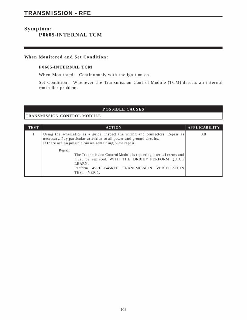
Symptom:P0605-INTERNAL TCM
When Monitored and Set Condition:
P0605-INTERNAL TCM
When Monitored: Continuously with the ignition on
Set Condition: Whenever the Transmission Control Module (TCM) detects an internalcontroller problem.
POSSIBLE CAUSES
TRANSMISSION CONTROL MODULE
TEST ACTION APPLICABILITY
1 Using the schematics as a guide, inspect the wiring and connectors. Repair asnecessary. Pay particular attention to all power and ground circuits.If there are no possible causes remaining, view repair.
All
RepairThe Transmission Control Module is reporting internal errors andmust be replaced. WITH THE DRBIIIt PERFORM QUICKLEARN.Perform 45RFE/545RFE TRANSMISSION VERIFICATIONTEST - VER 1.
102
TRANSMISSION - RFE
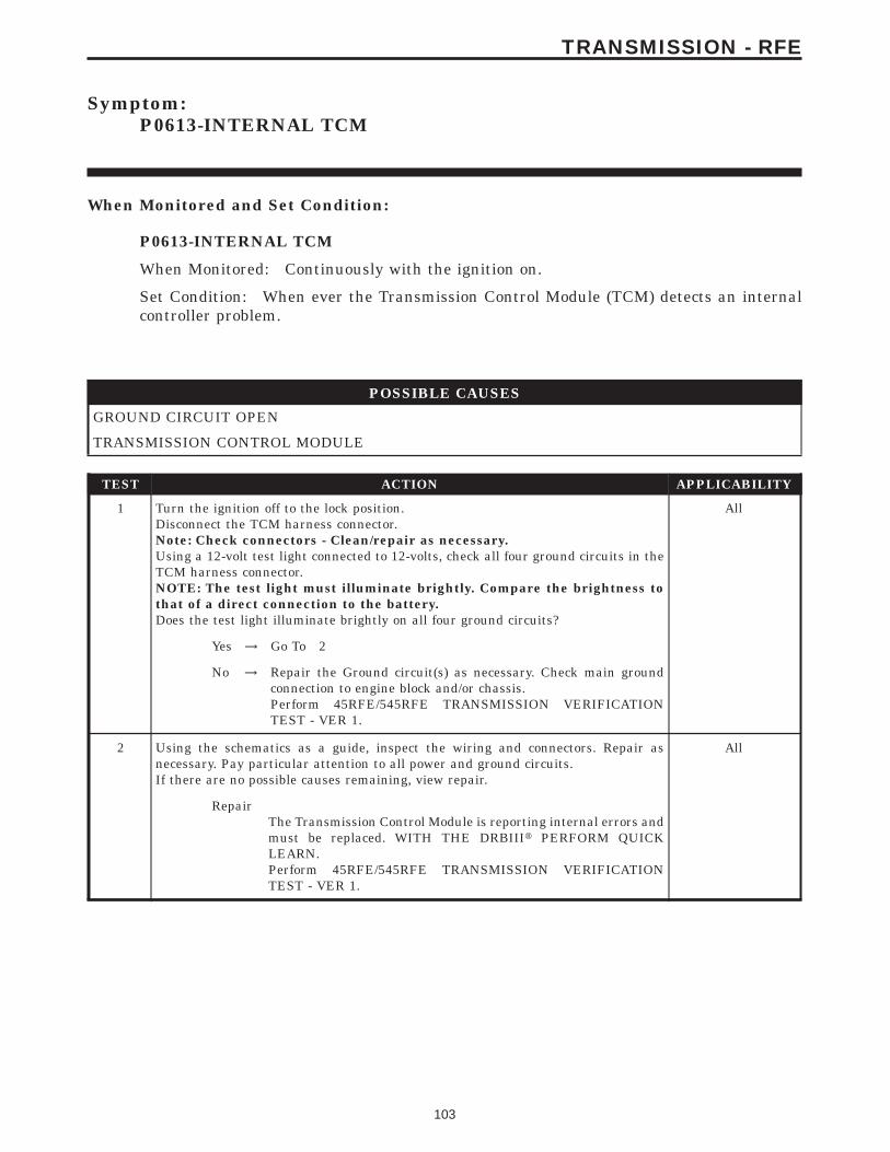
Symptom:P0613-INTERNAL TCM
When Monitored and Set Condition:
P0613-INTERNAL TCM
When Monitored: Continuously with the ignition on.
Set Condition: When ever the Transmission Control Module (TCM) detects an internalcontroller problem.
POSSIBLE CAUSES
GROUND CIRCUIT OPEN
TRANSMISSION CONTROL MODULE
TEST ACTION APPLICABILITY
1 Turn the ignition off to the lock position.Disconnect the TCM harness connector.Note: Check connectors - Clean/repair as necessary.Using a 12-volt test light connected to 12-volts, check all four ground circuits in theTCM harness connector.NOTE: The test light must illuminate brightly. Compare the brightness tothat of a direct connection to the battery.Does the test light illuminate brightly on all four ground circuits?
All
Yes → Go To 2
No → Repair the Ground circuit(s) as necessary. Check main groundconnection to engine block and/or chassis.Perform 45RFE/545RFE TRANSMISSION VERIFICATIONTEST - VER 1.
2 Using the schematics as a guide, inspect the wiring and connectors. Repair asnecessary. Pay particular attention to all power and ground circuits.If there are no possible causes remaining, view repair.
All
RepairThe Transmission Control Module is reporting internal errors andmust be replaced. WITH THE DRBIIIt PERFORM QUICKLEARN.Perform 45RFE/545RFE TRANSMISSION VERIFICATIONTEST - VER 1.
103
TRANSMISSION - RFE
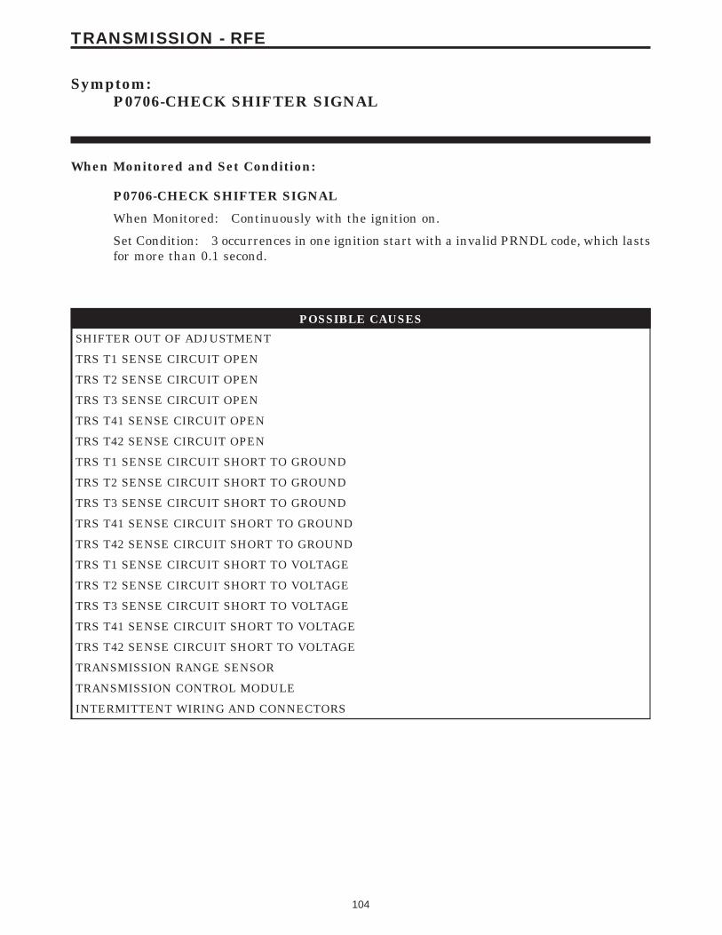
Symptom:P0706-CHECK SHIFTER SIGNAL
When Monitored and Set Condition:
P0706-CHECK SHIFTER SIGNAL
When Monitored: Continuously with the ignition on.
Set Condition: 3 occurrences in one ignition start with a invalid PRNDL code, which lastsfor more than 0.1 second.
POSSIBLE CAUSES
SHIFTER OUT OF ADJUSTMENT
TRS T1 SENSE CIRCUIT OPEN
TRS T2 SENSE CIRCUIT OPEN
TRS T3 SENSE CIRCUIT OPEN
TRS T41 SENSE CIRCUIT OPEN
TRS T42 SENSE CIRCUIT OPEN
TRS T1 SENSE CIRCUIT SHORT TO GROUND
TRS T2 SENSE CIRCUIT SHORT TO GROUND
TRS T3 SENSE CIRCUIT SHORT TO GROUND
TRS T41 SENSE CIRCUIT SHORT TO GROUND
TRS T42 SENSE CIRCUIT SHORT TO GROUND
TRS T1 SENSE CIRCUIT SHORT TO VOLTAGE
TRS T2 SENSE CIRCUIT SHORT TO VOLTAGE
TRS T3 SENSE CIRCUIT SHORT TO VOLTAGE
TRS T41 SENSE CIRCUIT SHORT TO VOLTAGE
TRS T42 SENSE CIRCUIT SHORT TO VOLTAGE
TRANSMISSION RANGE SENSOR
TRANSMISSION CONTROL MODULE
INTERMITTENT WIRING AND CONNECTORS
104
TRANSMISSION - RFE
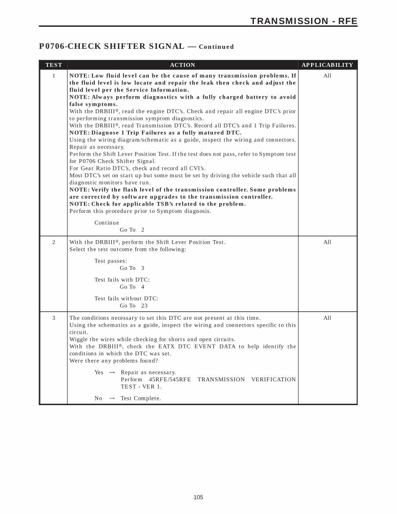
TEST ACTION APPLICABILITY
1 NOTE: Low fluid level can be the cause of many transmission problems. Ifthe fluid level is low locate and repair the leak then check and adjust thefluid level per the Service Information.NOTE: Always perform diagnostics with a fully charged battery to avoidfalse symptoms.With the DRBIIIt, read the engine DTC’s. Check and repair all engine DTC’s priorto performing transmission symptom diagnostics.With the DRBIIIt, read Transmission DTC’s. Record all DTC’s and 1 Trip Failures.NOTE: Diagnose 1 Trip Failures as a fully matured DTC.Using the wiring diagram/schematic as a guide, inspect the wiring and connectors.Repair as necessary.Perform the Shift Lever Position Test. If the test does not pass, refer to Symptom testfor P0706 Check Shifter Signal.For Gear Ratio DTC’s, check and record all CVI’s.Most DTC’s set on start up but some must be set by driving the vehicle such that alldiagnostic monitors have run.NOTE: Verify the flash level of the transmission controller. Some problemsare corrected by software upgrades to the transmission controller.NOTE: Check for applicable TSB’s related to the problem.Perform this procedure prior to Symptom diagnosis.
All
ContinueGo To 2
2 With the DRBIIIt, perform the Shift Lever Position Test.Select the test outcome from the following:
All
Test passes:Go To 3
Test fails with DTC:Go To 4
Test fails without DTC:Go To 23
3 The conditions necessary to set this DTC are not present at this time.Using the schematics as a guide, inspect the wiring and connectors specific to thiscircuit.Wiggle the wires while checking for shorts and open circuits.With the DRBIIIt, check the EATX DTC EVENT DATA to help identify theconditions in which the DTC was set.Were there any problems found?
All
Yes → Repair as necessary.Perform 45RFE/545RFE TRANSMISSION VERIFICATIONTEST - VER 1.
No → Test Complete.
105
TRANSMISSION - RFE
P0706-CHECK SHIFTER SIGNAL — Continued
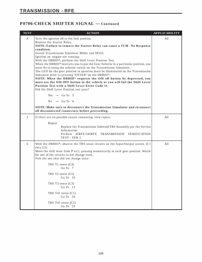
TEST ACTION APPLICABILITY
4 Turn the ignition off to the lock position.Remove the Starter Relay.NOTE: Failure to remove the Starter Relay can cause a TCM - No Responsecondition.Install Transmission Simulator Miller tool #8333.Ignition on, engine not running.With the DRBIIIt, perform the Shift Lever Position Test.When the DRBIIIt instructs you to put the Gear Selector in a particular position, youmust do so using the selector switch on the Transmission Simulator.The LED for the gear position in question must be illuminated on the TransmissionSimulator prior to pressing 9ENTER9 on the DRBIIIt.NOTE: When the DRBIIIt requests the O/D off button be depressed, youmust use the O/D OFF button in the vehicle or you will fail the Shift LeverPosition Test with a Shift Lever Error Code 11.Did the Shift Lever Position test pass?
All
Yes → Go To 5
No → Go To 6
NOTE: Make sure to disconnect the Transmission Simulator and reconnectall disconnected connectors before proceeding.
5 If there are no possible causes remaining, view repair. All
RepairReplace the Transmission Solenoid/TRS Assembly per the ServiceInformation.Perform 45RFE/545RFE TRANSMISSION VERIFICATIONTEST - VER 1.
6 With the DRBIIIt, observe the TRS sense circuits on the Input/Output screen. (C1thru C5)Move the shift lever from P to L, pausing momentarily in each gear position. Watchfor one of the circuits to not change state.Pick the one that did not change state.
All
TRS T1 sense (C4)Go To 7
TRS T2 sense (C5)Go To 10
TRS T3 sense (C3)Go To 13
TRS T41 sense (C1)Go To 16
TRS T42 sense (C2)Go To 19
106
TRANSMISSION - RFE
P0706-CHECK SHIFTER SIGNAL — Continued
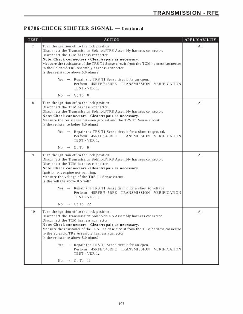
TEST ACTION APPLICABILITY
7 Turn the ignition off to the lock position.Disconnect the Transmission Solenoid/TRS Assembly harness connector.Disconnect the TCM harness connector.Note: Check connectors - Clean/repair as necessary.Measure the resistance of the TRS T1 Sense circuit from the TCM harness connectorto the Solenoid/TRS Assembly harness connector.Is the resistance above 5.0 ohms?
All
Yes → Repair the TRS T1 Sense circuit for an open.Perform 45RFE/545RFE TRANSMISSION VERIFICATIONTEST - VER 1.
No → Go To 8
8 Turn the ignition off to the lock position.Disconnect the TCM harness connector.Disconnect the Transmission Solenoid/TRS Assembly harness connector.Note: Check connectors - Clean/repair as necessary.Measure the resistance between ground and the TRS T1 Sense circuit.Is the resistance below 5.0 ohms?
All
Yes → Repair the TRS T1 Sense circuit for a short to ground.Perform 45RFE/545RFE TRANSMISSION VERIFICATIONTEST - VER 1.
No → Go To 9
9 Turn the ignition off to the lock position.Disconnect the Transmission Solenoid/TRS Assembly harness connector.Disconnect the TCM harness connector.Note: Check connectors - Clean/repair as necessary.Ignition on, engine not running.Measure the voltage of the TRS T1 Sense circuit.Is the voltage above 0.5 volt?
All
Yes → Repair the TRS T1 Sense circuit for a short to voltage.Perform 45RFE/545RFE TRANSMISSION VERIFICATIONTEST - VER 1.
No → Go To 22
10 Turn the ignition off to the lock position.Disconnect the Transmission Solenoid/TRS Assembly harness connector.Disconnect the TCM harness connector.Note: Check connectors - Clean/repair as necessary.Measure the resistance of the TRS T2 Sense circuit from the TCM harness connectorto the Solenoid/TRS Assembly harness connector.Is the resistance above 5.0 ohms?
All
Yes → Repair the TRS T2 Sense circuit for an open.Perform 45RFE/545RFE TRANSMISSION VERIFICATIONTEST - VER 1.
No → Go To 11
107
TRANSMISSION - RFE
P0706-CHECK SHIFTER SIGNAL — Continued
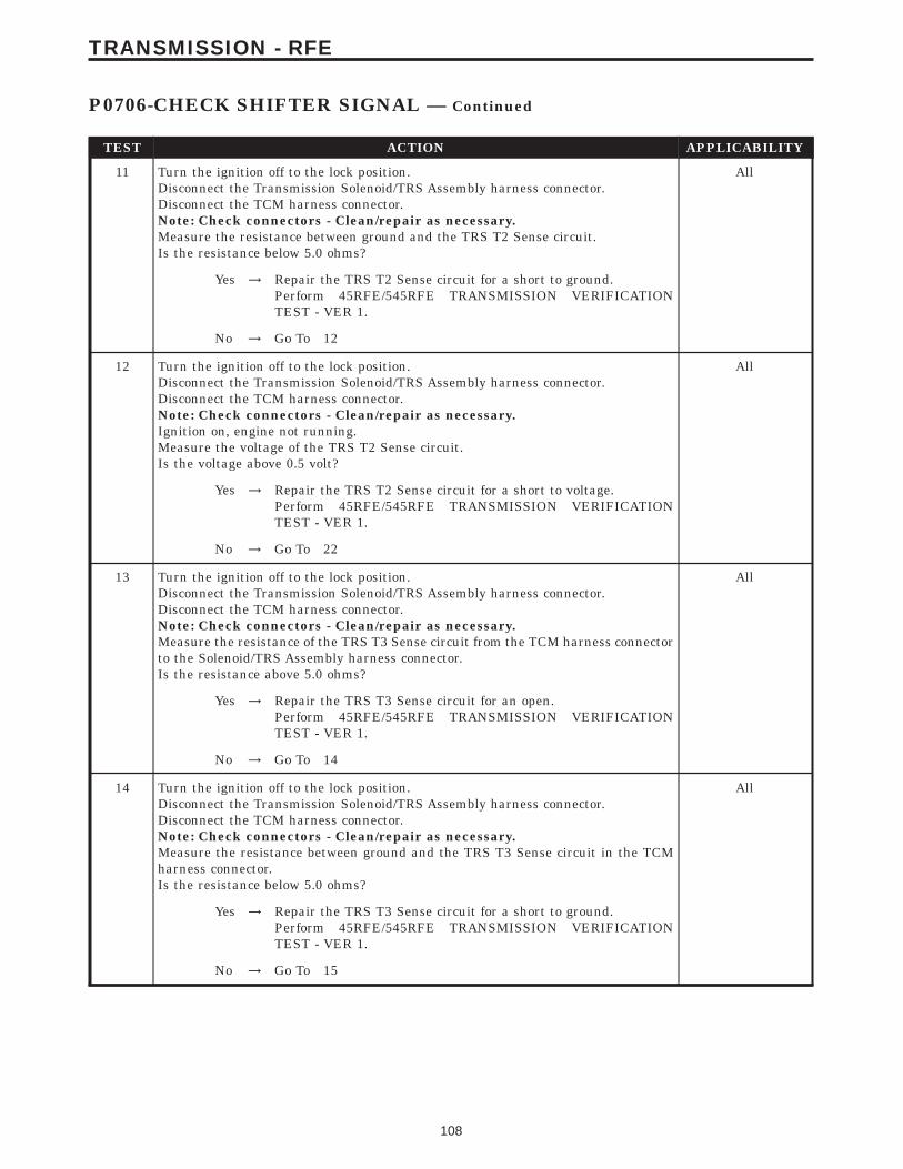
TEST ACTION APPLICABILITY
11 Turn the ignition off to the lock position.Disconnect the Transmission Solenoid/TRS Assembly harness connector.Disconnect the TCM harness connector.Note: Check connectors - Clean/repair as necessary.Measure the resistance between ground and the TRS T2 Sense circuit.Is the resistance below 5.0 ohms?
All
Yes → Repair the TRS T2 Sense circuit for a short to ground.Perform 45RFE/545RFE TRANSMISSION VERIFICATIONTEST - VER 1.
No → Go To 12
12 Turn the ignition off to the lock position.Disconnect the Transmission Solenoid/TRS Assembly harness connector.Disconnect the TCM harness connector.Note: Check connectors - Clean/repair as necessary.Ignition on, engine not running.Measure the voltage of the TRS T2 Sense circuit.Is the voltage above 0.5 volt?
All
Yes → Repair the TRS T2 Sense circuit for a short to voltage.Perform 45RFE/545RFE TRANSMISSION VERIFICATIONTEST - VER 1.
No → Go To 22
13 Turn the ignition off to the lock position.Disconnect the Transmission Solenoid/TRS Assembly harness connector.Disconnect the TCM harness connector.Note: Check connectors - Clean/repair as necessary.Measure the resistance of the TRS T3 Sense circuit from the TCM harness connectorto the Solenoid/TRS Assembly harness connector.Is the resistance above 5.0 ohms?
All
Yes → Repair the TRS T3 Sense circuit for an open.Perform 45RFE/545RFE TRANSMISSION VERIFICATIONTEST - VER 1.
No → Go To 14
14 Turn the ignition off to the lock position.Disconnect the Transmission Solenoid/TRS Assembly harness connector.Disconnect the TCM harness connector.Note: Check connectors - Clean/repair as necessary.Measure the resistance between ground and the TRS T3 Sense circuit in the TCMharness connector.Is the resistance below 5.0 ohms?
All
Yes → Repair the TRS T3 Sense circuit for a short to ground.Perform 45RFE/545RFE TRANSMISSION VERIFICATIONTEST - VER 1.
No → Go To 15
108
TRANSMISSION - RFE
P0706-CHECK SHIFTER SIGNAL — Continued
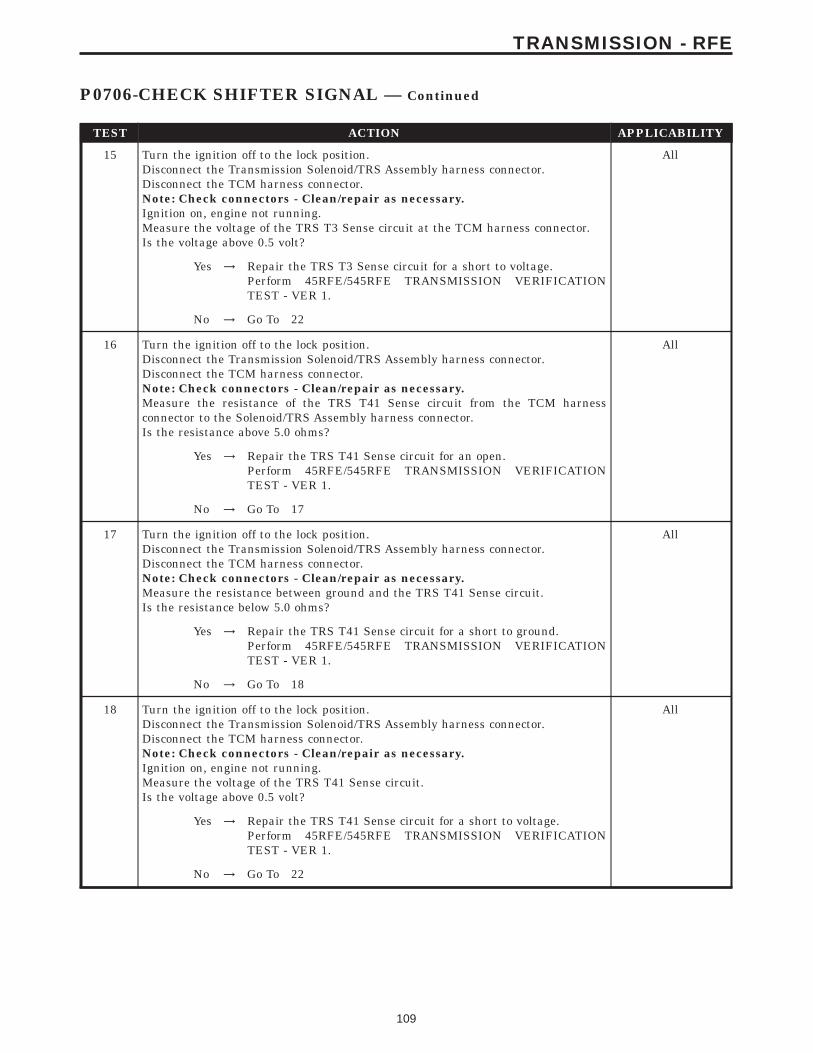
TEST ACTION APPLICABILITY
15 Turn the ignition off to the lock position.Disconnect the Transmission Solenoid/TRS Assembly harness connector.Disconnect the TCM harness connector.Note: Check connectors - Clean/repair as necessary.Ignition on, engine not running.Measure the voltage of the TRS T3 Sense circuit at the TCM harness connector.Is the voltage above 0.5 volt?
All
Yes → Repair the TRS T3 Sense circuit for a short to voltage.Perform 45RFE/545RFE TRANSMISSION VERIFICATIONTEST - VER 1.
No → Go To 22
16 Turn the ignition off to the lock position.Disconnect the Transmission Solenoid/TRS Assembly harness connector.Disconnect the TCM harness connector.Note: Check connectors - Clean/repair as necessary.Measure the resistance of the TRS T41 Sense circuit from the TCM harnessconnector to the Solenoid/TRS Assembly harness connector.Is the resistance above 5.0 ohms?
All
Yes → Repair the TRS T41 Sense circuit for an open.Perform 45RFE/545RFE TRANSMISSION VERIFICATIONTEST - VER 1.
No → Go To 17
17 Turn the ignition off to the lock position.Disconnect the Transmission Solenoid/TRS Assembly harness connector.Disconnect the TCM harness connector.Note: Check connectors - Clean/repair as necessary.Measure the resistance between ground and the TRS T41 Sense circuit.Is the resistance below 5.0 ohms?
All
Yes → Repair the TRS T41 Sense circuit for a short to ground.Perform 45RFE/545RFE TRANSMISSION VERIFICATIONTEST - VER 1.
No → Go To 18
18 Turn the ignition off to the lock position.Disconnect the Transmission Solenoid/TRS Assembly harness connector.Disconnect the TCM harness connector.Note: Check connectors - Clean/repair as necessary.Ignition on, engine not running.Measure the voltage of the TRS T41 Sense circuit.Is the voltage above 0.5 volt?
All
Yes → Repair the TRS T41 Sense circuit for a short to voltage.Perform 45RFE/545RFE TRANSMISSION VERIFICATIONTEST - VER 1.
No → Go To 22
109
TRANSMISSION - RFE
P0706-CHECK SHIFTER SIGNAL — Continued
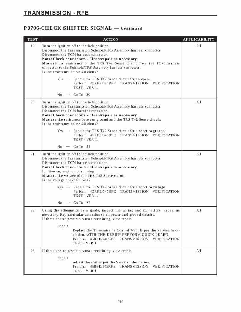
TEST ACTION APPLICABILITY
19 Turn the ignition off to the lock position.Disconnect the Transmission Solenoid/TRS Assembly harness connector.Disconnect the TCM harness connector.Note: Check connectors - Clean/repair as necessary.Measure the resistance of the TRS T42 Sense circuit from the TCM harnessconnector to the Solenoid/TRS Assembly harness connector.Is the resistance above 5.0 ohms?
All
Yes → Repair the TRS T42 Sense circuit for an open.Perform 45RFE/545RFE TRANSMISSION VERIFICATIONTEST - VER 1.
No → Go To 20
20 Turn the ignition off to the lock position.Disconnect the Transmission Solenoid/TRS Assembly harness connector.Disconnect the TCM harness connector.Note: Check connectors - Clean/repair as necessary.Measure the resistance between ground and the TRS T42 Sense circuit.Is the resistance below 5.0 ohms?
All
Yes → Repair the TRS T42 Sense circuit for a short to ground.Perform 45RFE/545RFE TRANSMISSION VERIFICATIONTEST - VER 1.
No → Go To 21
21 Turn the ignition off to the lock position.Disconnect the Transmission Solenoid/TRS Assembly harness connector.Disconnect the TCM harness connector.Note: Check connectors - Clean/repair as necessary.Ignition on, engine not running.Measure the voltage of the TRS T42 Sense circuit.Is the voltage above 0.5 volt?
All
Yes → Repair the TRS T42 Sense circuit for a short to voltage.Perform 45RFE/545RFE TRANSMISSION VERIFICATIONTEST - VER 1.
No → Go To 22
22 Using the schematics as a guide, inspect the wiring and connectors. Repair asnecessary. Pay particular attention to all power and ground circuits.If there are no possible causes remaining, view repair.
All
RepairReplace the Transmission Control Module per the Service Infor-mation. WITH THE DRBIIIt PERFORM QUICK LEARN.Perform 45RFE/545RFE TRANSMISSION VERIFICATIONTEST - VER 1.
23 If there are no possible causes remaining, view repair. All
RepairAdjust the shifter per the Service Information.Perform 45RFE/545RFE TRANSMISSION VERIFICATIONTEST - VER 1.
110
TRANSMISSION - RFE
P0706-CHECK SHIFTER SIGNAL — Continued
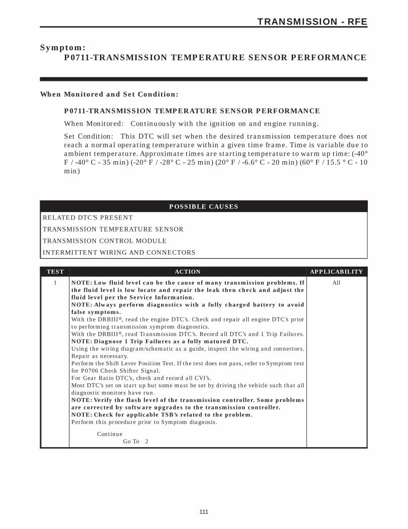
Symptom:P0711-TRANSMISSION TEMPERATURE SENSOR PERFORMANCE
When Monitored and Set Condition:
P0711-TRANSMISSION TEMPERATURE SENSOR PERFORMANCE
When Monitored: Continuously with the ignition on and engine running.
Set Condition: This DTC will set when the desired transmission temperature does notreach a normal operating temperature within a given time frame. Time is variable due toambient temperature. Approximate times are starting temperature to warm up time: (-40°F / -40° C - 35 min) (-20° F / -28° C - 25 min) (20° F / -6.6° C - 20 min) (60° F / 15.5 ° C - 10min)
POSSIBLE CAUSES
RELATED DTC’S PRESENT
TRANSMISSION TEMPERATURE SENSOR
TRANSMISSION CONTROL MODULE
INTERMITTENT WIRING AND CONNECTORS
TEST ACTION APPLICABILITY
1 NOTE: Low fluid level can be the cause of many transmission problems. Ifthe fluid level is low locate and repair the leak then check and adjust thefluid level per the Service Information.NOTE: Always perform diagnostics with a fully charged battery to avoidfalse symptoms.With the DRBIIIt, read the engine DTC’s. Check and repair all engine DTC’s priorto performing transmission symptom diagnostics.With the DRBIIIt, read Transmission DTC’s. Record all DTC’s and 1 Trip Failures.NOTE: Diagnose 1 Trip Failures as a fully matured DTC.Using the wiring diagram/schematic as a guide, inspect the wiring and connectors.Repair as necessary.Perform the Shift Lever Position Test. If the test does not pass, refer to Symptom testfor P0706 Check Shifter Signal.For Gear Ratio DTC’s, check and record all CVI’s.Most DTC’s set on start up but some must be set by driving the vehicle such that alldiagnostic monitors have run.NOTE: Verify the flash level of the transmission controller. Some problemsare corrected by software upgrades to the transmission controller.NOTE: Check for applicable TSB’s related to the problem.Perform this procedure prior to Symptom diagnosis.
All
ContinueGo To 2
111
TRANSMISSION - RFE
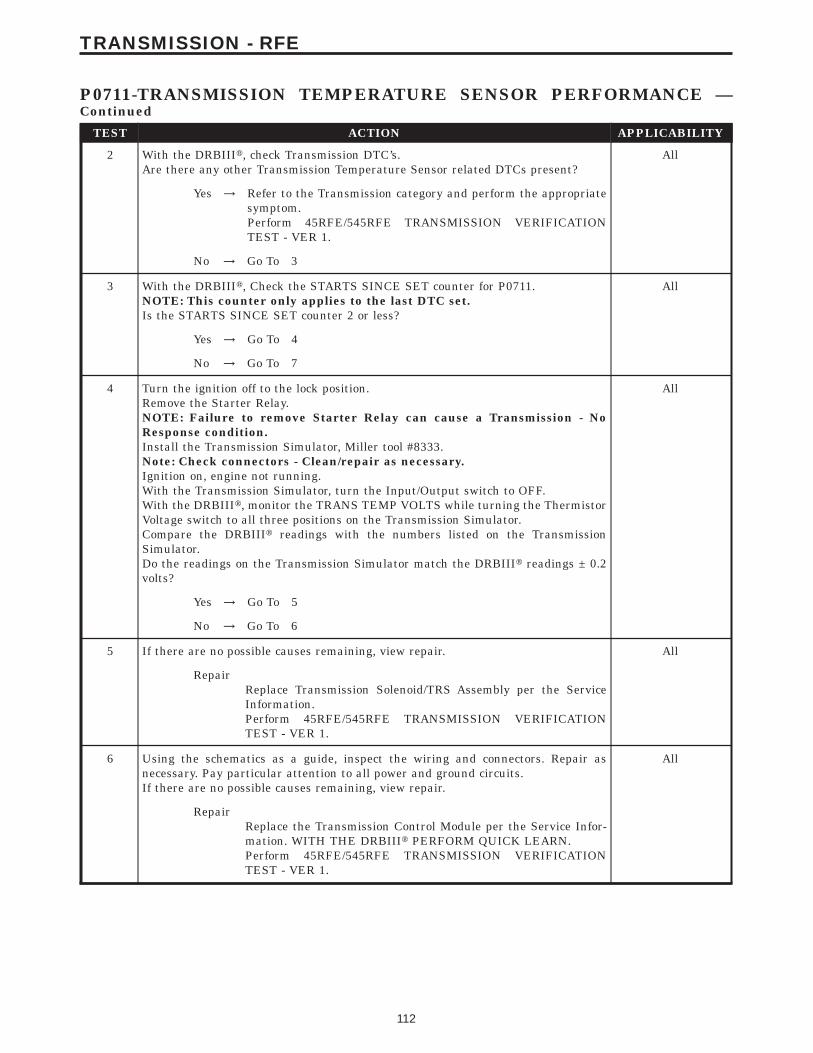
TEST ACTION APPLICABILITY
2 With the DRBIIIt, check Transmission DTC’s.Are there any other Transmission Temperature Sensor related DTCs present?
All
Yes → Refer to the Transmission category and perform the appropriatesymptom.Perform 45RFE/545RFE TRANSMISSION VERIFICATIONTEST - VER 1.
No → Go To 3
3 With the DRBIIIt, Check the STARTS SINCE SET counter for P0711.NOTE: This counter only applies to the last DTC set.Is the STARTS SINCE SET counter 2 or less?
All
Yes → Go To 4
No → Go To 7
4 Turn the ignition off to the lock position.Remove the Starter Relay.NOTE: Failure to remove Starter Relay can cause a Transmission - NoResponse condition.Install the Transmission Simulator, Miller tool #8333.Note: Check connectors - Clean/repair as necessary.Ignition on, engine not running.With the Transmission Simulator, turn the Input/Output switch to OFF.With the DRBIIIt, monitor the TRANS TEMP VOLTS while turning the ThermistorVoltage switch to all three positions on the Transmission Simulator.Compare the DRBIIIt readings with the numbers listed on the TransmissionSimulator.Do the readings on the Transmission Simulator match the DRBIIIt readings ± 0.2volts?
All
Yes → Go To 5
No → Go To 6
5 If there are no possible causes remaining, view repair. All
RepairReplace Transmission Solenoid/TRS Assembly per the ServiceInformation.Perform 45RFE/545RFE TRANSMISSION VERIFICATIONTEST - VER 1.
6 Using the schematics as a guide, inspect the wiring and connectors. Repair asnecessary. Pay particular attention to all power and ground circuits.If there are no possible causes remaining, view repair.
All
RepairReplace the Transmission Control Module per the Service Infor-mation. WITH THE DRBIIIt PERFORM QUICK LEARN.Perform 45RFE/545RFE TRANSMISSION VERIFICATIONTEST - VER 1.
112
TRANSMISSION - RFE
P0711-TRANSMISSION TEMPERATURE SENSOR PERFORMANCE —Continued
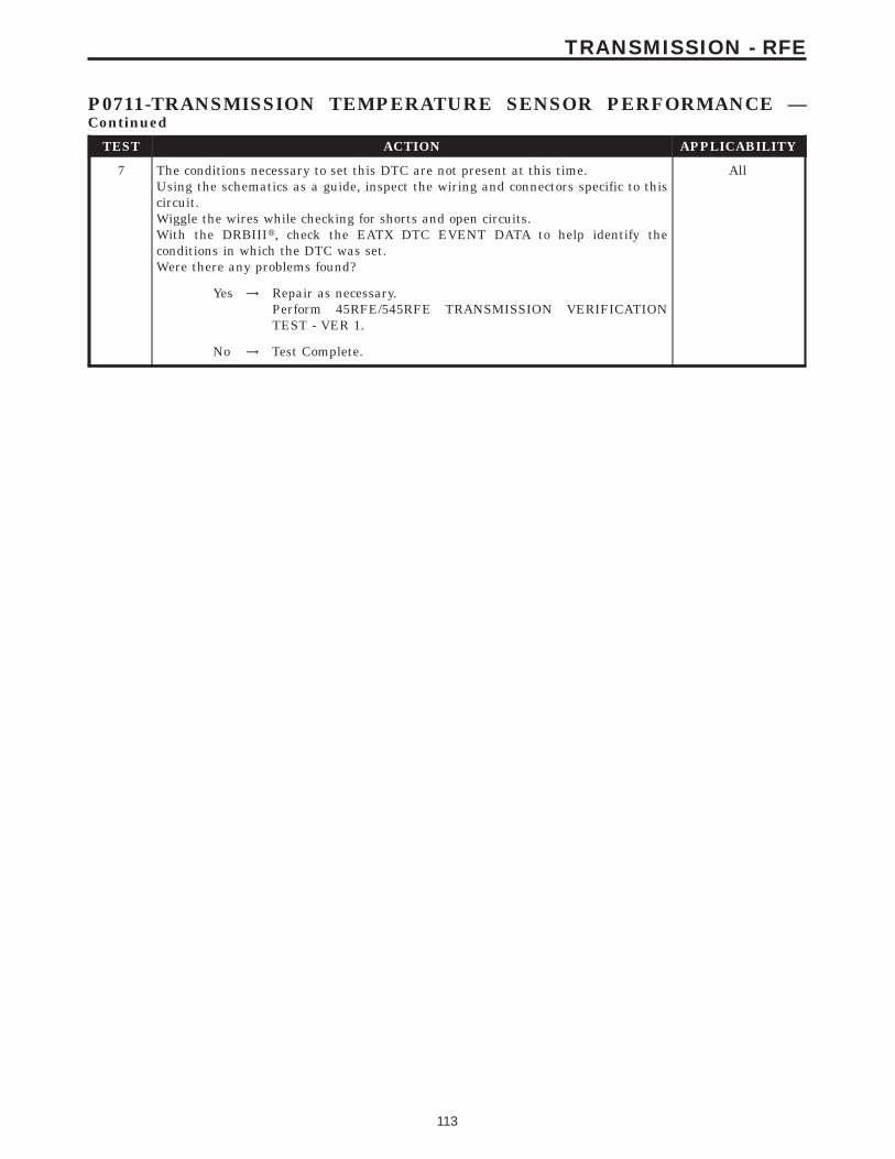
TEST ACTION APPLICABILITY
7 The conditions necessary to set this DTC are not present at this time.Using the schematics as a guide, inspect the wiring and connectors specific to thiscircuit.Wiggle the wires while checking for shorts and open circuits.With the DRBIIIt, check the EATX DTC EVENT DATA to help identify theconditions in which the DTC was set.Were there any problems found?
All
Yes → Repair as necessary.Perform 45RFE/545RFE TRANSMISSION VERIFICATIONTEST - VER 1.
No → Test Complete.
113
TRANSMISSION - RFE
P0711-TRANSMISSION TEMPERATURE SENSOR PERFORMANCE —Continued
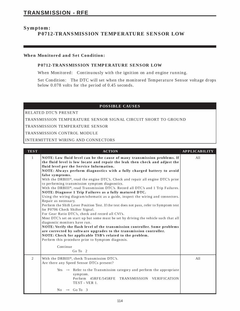
Symptom:P0712-TRANSMISSION TEMPERATURE SENSOR LOW
When Monitored and Set Condition:
P0712-TRANSMISSION TEMPERATURE SENSOR LOW
When Monitored: Continuously with the ignition on and engine running.
Set Condition: The DTC will set when the monitored Temperature Sensor voltage dropsbelow 0.078 volts for the period of 0.45 seconds.
POSSIBLE CAUSES
RELATED DTC’S PRESENT
TRANSMISSION TEMPERATURE SENSOR SIGNAL CIRCUIT SHORT TO GROUND
TRANSMISSION TEMPERATURE SENSOR
TRANSMISSION CONTROL MODULE
INTERMITTENT WIRING AND CONNECTORS
TEST ACTION APPLICABILITY
1 NOTE: Low fluid level can be the cause of many transmission problems. Ifthe fluid level is low locate and repair the leak then check and adjust thefluid level per the Service Information.NOTE: Always perform diagnostics with a fully charged battery to avoidfalse symptoms.With the DRBIIIt, read the engine DTC’s. Check and repair all engine DTC’s priorto performing transmission symptom diagnostics.With the DRBIIIt, read Transmission DTC’s. Record all DTC’s and 1 Trip Failures.NOTE: Diagnose 1 Trip Failures as a fully matured DTC.Using the wiring diagram/schematic as a guide, inspect the wiring and connectors.Repair as necessary.Perform the Shift Lever Position Test. If the test does not pass, refer to Symptom testfor P0706 Check Shifter Signal.For Gear Ratio DTC’s, check and record all CVI’s.Most DTC’s set on start up but some must be set by driving the vehicle such that alldiagnostic monitors have run.NOTE: Verify the flash level of the transmission controller. Some problemsare corrected by software upgrades to the transmission controller.NOTE: Check for applicable TSB’s related to the problem.Perform this procedure prior to Symptom diagnosis.
All
ContinueGo To 2
2 With the DRBIIIt, check Transmission DTC’s.Are there any Speed Sensor DTCs present?
All
Yes → Refer to the Transmission category and perform the appropriatesymptom.Perform 45RFE/545RFE TRANSMISSION VERIFICATIONTEST - VER 1.
No → Go To 3
114
TRANSMISSION - RFE
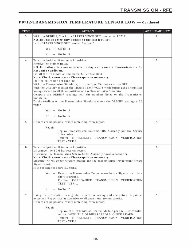
TEST ACTION APPLICABILITY
3 With the DRBIIIt, Check the STARTS SINCE SET counter for P0712.NOTE: This counter only applies to the last DTC set.Is the STARTS SINCE SET counter 2 or less?
All
Yes → Go To 4
No → Go To 8
4 Turn the ignition off to the lock position.Remove the Starter Relay.NOTE: Failure to remove Starter Relay can cause a Transmission - NoResponse condition.Install the Transmission Simulator, Miller tool #8333.Note: Check connectors - Clean/repair as necessary.Ignition on, engine not running.With the Transmission Simulator, turn the Input/Output switch to OFF.With the DRBIIIt, monitor the TRANS TEMP VOLTS while turning the ThermistorVoltage switch to all three positions on the Transmission Simulator.Compare the DRBIIIt readings with the numbers listed on the TransmissionSimulator.Do the readings on the Transmission Simulator match the DRBIIIt readings ± 0.2volts?
All
Yes → Go To 5
No → Go To 6
5 If there are no possible causes remaining, view repair. All
RepairReplace Transmission Solenoid/TRS Assembly per the ServiceInformation.Perform 45RFE/545RFE TRANSMISSION VERIFICATIONTEST - VER 1.
6 Turn the ignition off to the lock position.Disconnect the TCM harness connector..Disconnect the Transmission Solenoid/TRS Assembly harness connector.Note: Check connectors - Clean/repair as necessary.Measure the resistance between ground and the Transmission Temperature SensorSignal circuit.Is the resistance below 5.0 ohms?
All
Yes → Repair the Transmission Temperature Sensor Signal circuit for ashort to ground.Perform 45RFE/545RFE TRANSMISSION VERIFICATIONTEST - VER 1.
No → Go To 7
7 Using the schematics as a guide, inspect the wiring and connectors. Repair asnecessary. Pay particular attention to all power and ground circuits.If there are no possible causes remaining, view repair.
All
RepairReplace the Transmission Control Module per the Service Infor-mation. WITH THE DRBIIIt PERFORM QUICK LEARN.Perform 45RFE/545RFE TRANSMISSION VERIFICATIONTEST - VER 1.
115
TRANSMISSION - RFE
P0712-TRANSMISSION TEMPERATURE SENSOR LOW — Continued

TEST ACTION APPLICABILITY
8 The conditions necessary to set this DTC are not present at this time.Using the schematics as a guide, inspect the wiring and connectors specific to thiscircuit.Wiggle the wires while checking for shorts and open circuits.With the DRBIIIt, check the EATX DTC EVENT DATA to help identify theconditions in which the DTC was set.Were there any problems found?
All
Yes → Repair as necessary.Perform 45RFE/545RFE TRANSMISSION VERIFICATIONTEST - VER 1.
No → Test Complete.
116
TRANSMISSION - RFE
P0712-TRANSMISSION TEMPERATURE SENSOR LOW — Continued
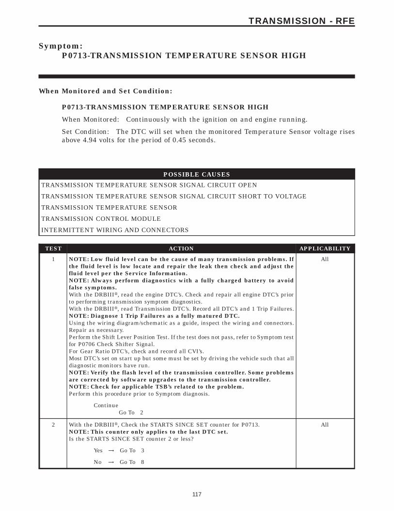
Symptom:P0713-TRANSMISSION TEMPERATURE SENSOR HIGH
When Monitored and Set Condition:
P0713-TRANSMISSION TEMPERATURE SENSOR HIGH
When Monitored: Continuously with the ignition on and engine running.
Set Condition: The DTC will set when the monitored Temperature Sensor voltage risesabove 4.94 volts for the period of 0.45 seconds.
POSSIBLE CAUSES
TRANSMISSION TEMPERATURE SENSOR SIGNAL CIRCUIT OPEN
TRANSMISSION TEMPERATURE SENSOR SIGNAL CIRCUIT SHORT TO VOLTAGE
TRANSMISSION TEMPERATURE SENSOR
TRANSMISSION CONTROL MODULE
INTERMITTENT WIRING AND CONNECTORS
TEST ACTION APPLICABILITY
1 NOTE: Low fluid level can be the cause of many transmission problems. Ifthe fluid level is low locate and repair the leak then check and adjust thefluid level per the Service Information.NOTE: Always perform diagnostics with a fully charged battery to avoidfalse symptoms.With the DRBIIIt, read the engine DTC’s. Check and repair all engine DTC’s priorto performing transmission symptom diagnostics.With the DRBIIIt, read Transmission DTC’s. Record all DTC’s and 1 Trip Failures.NOTE: Diagnose 1 Trip Failures as a fully matured DTC.Using the wiring diagram/schematic as a guide, inspect the wiring and connectors.Repair as necessary.Perform the Shift Lever Position Test. If the test does not pass, refer to Symptom testfor P0706 Check Shifter Signal.For Gear Ratio DTC’s, check and record all CVI’s.Most DTC’s set on start up but some must be set by driving the vehicle such that alldiagnostic monitors have run.NOTE: Verify the flash level of the transmission controller. Some problemsare corrected by software upgrades to the transmission controller.NOTE: Check for applicable TSB’s related to the problem.Perform this procedure prior to Symptom diagnosis.
All
ContinueGo To 2
2 With the DRBIIIt, Check the STARTS SINCE SET counter for P0713.NOTE: This counter only applies to the last DTC set.Is the STARTS SINCE SET counter 2 or less?
All
Yes → Go To 3
No → Go To 8
117
TRANSMISSION - RFE
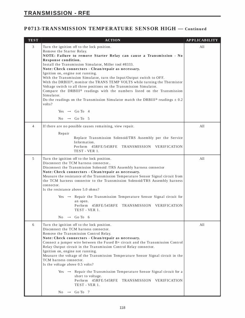
TEST ACTION APPLICABILITY
3 Turn the ignition off to the lock position.Remove the Starter Relay.NOTE: Failure to remove Starter Relay can cause a Transmission - NoResponse condition.Install the Transmission Simulator, Miller tool #8333.Note: Check connectors - Clean/repair as necessary.Ignition on, engine not running.With the Transmission Simulator, turn the Input/Output switch to OFF.With the DRBIIIt, monitor the TRANS TEMP VOLTS while turning the ThermistorVoltage switch to all three positions on the Transmission Simulator.Compare the DRBIIIt readings with the numbers listed on the TransmissionSimulator.Do the readings on the Transmission Simulator match the DRBIIIt readings ± 0.2volts?
All
Yes → Go To 4
No → Go To 5
4 If there are no possible causes remaining, view repair. All
RepairReplace Transmission Solenoid/TRS Assembly per the ServiceInformation.Perform 45RFE/545RFE TRANSMISSION VERIFICATIONTEST - VER 1.
5 Turn the ignition off to the lock position.Disconnect the TCM harness connector..Disconnect the Transmission Solenoid /TRS Assembly harness connectorNote: Check connectors - Clean/repair as necessary.Measure the resistance of the Transmission Temperature Sensor Signal circuit fromthe TCM harness connector to the Transmission Solenoid/TRS Assembly harnessconnector.Is the resistance above 5.0 ohms?
All
Yes → Repair the Transmission Temperature Sensor Signal circuit foran open.Perform 45RFE/545RFE TRANSMISSION VERIFICATIONTEST - VER 1.
No → Go To 6
6 Turn the ignition off to the lock position.Disconnect the TCM harness connector.Remove the Transmission Control Relay.Note: Check connectors - Clean/repair as necessary.Connect a jumper wire between the Fused B+ circuit and the Transmission ControlRelay Output circuit in the Transmission Control Relay connector.Ignition on, engine not running.Measure the voltage of the Transmission Temperature Sensor Signal circuit in theTCM harness connector.Is the voltage above 0.5 volts?
All
Yes → Repair the Transmission Temperature Sensor Signal circuit for ashort to voltage.Perform 45RFE/545RFE TRANSMISSION VERIFICATIONTEST - VER 1.
No → Go To 7
118
TRANSMISSION - RFE
P0713-TRANSMISSION TEMPERATURE SENSOR HIGH — Continued
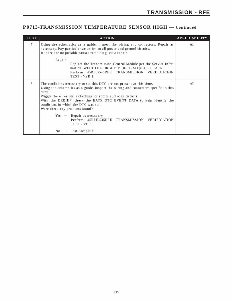
TEST ACTION APPLICABILITY
7 Using the schematics as a guide, inspect the wiring and connectors. Repair asnecessary. Pay particular attention to all power and ground circuits.If there are no possible causes remaining, view repair.
All
RepairReplace the Transmission Control Module per the Service Infor-mation. WITH THE DRBIIIt PERFORM QUICK LEARN.Perform 45RFE/545RFE TRANSMISSION VERIFICATIONTEST - VER 1.
8 The conditions necessary to set this DTC are not present at this time.Using the schematics as a guide, inspect the wiring and connectors specific to thiscircuit.Wiggle the wires while checking for shorts and open circuits.With the DRBIIIt, check the EATX DTC EVENT DATA to help identify theconditions in which the DTC was set.Were there any problems found?
All
Yes → Repair as necessary.Perform 45RFE/545RFE TRANSMISSION VERIFICATIONTEST - VER 1.
No → Test Complete.
119
TRANSMISSION - RFE
P0713-TRANSMISSION TEMPERATURE SENSOR HIGH — Continued
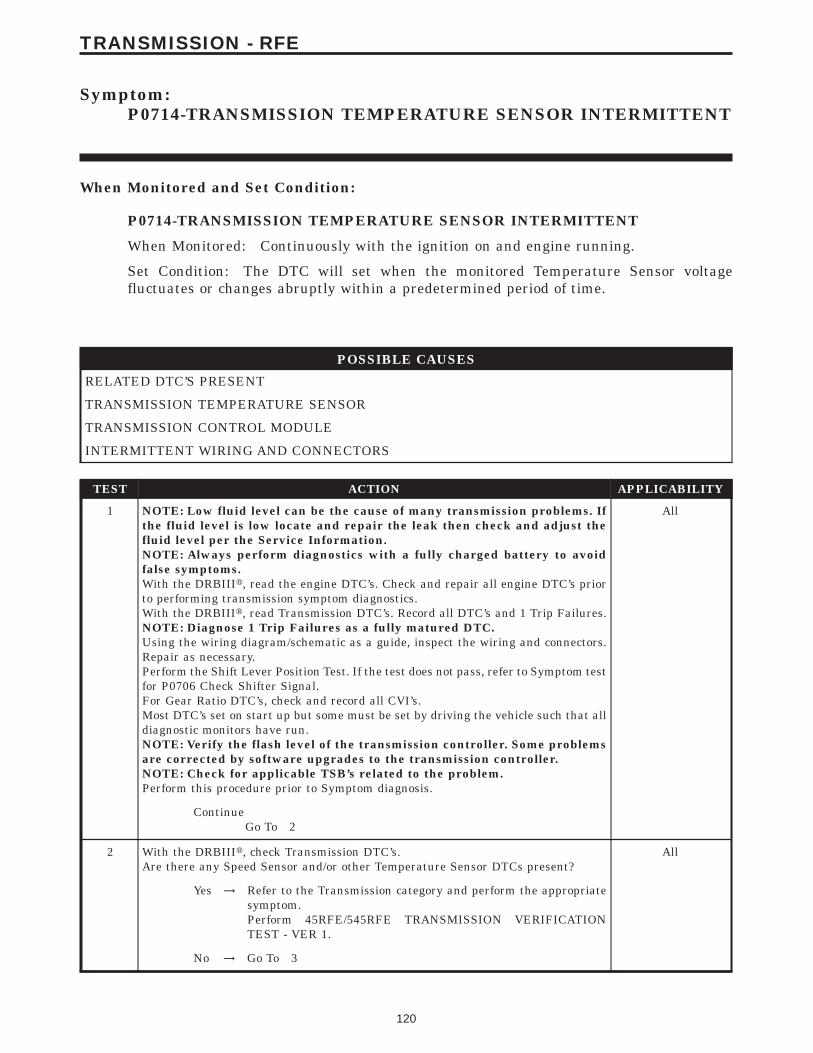
Symptom:P0714-TRANSMISSION TEMPERATURE SENSOR INTERMITTENT
When Monitored and Set Condition:
P0714-TRANSMISSION TEMPERATURE SENSOR INTERMITTENT
When Monitored: Continuously with the ignition on and engine running.
Set Condition: The DTC will set when the monitored Temperature Sensor voltagefluctuates or changes abruptly within a predetermined period of time.
POSSIBLE CAUSES
RELATED DTC’S PRESENT
TRANSMISSION TEMPERATURE SENSOR
TRANSMISSION CONTROL MODULE
INTERMITTENT WIRING AND CONNECTORS
TEST ACTION APPLICABILITY
1 NOTE: Low fluid level can be the cause of many transmission problems. Ifthe fluid level is low locate and repair the leak then check and adjust thefluid level per the Service Information.NOTE: Always perform diagnostics with a fully charged battery to avoidfalse symptoms.With the DRBIIIt, read the engine DTC’s. Check and repair all engine DTC’s priorto performing transmission symptom diagnostics.With the DRBIIIt, read Transmission DTC’s. Record all DTC’s and 1 Trip Failures.NOTE: Diagnose 1 Trip Failures as a fully matured DTC.Using the wiring diagram/schematic as a guide, inspect the wiring and connectors.Repair as necessary.Perform the Shift Lever Position Test. If the test does not pass, refer to Symptom testfor P0706 Check Shifter Signal.For Gear Ratio DTC’s, check and record all CVI’s.Most DTC’s set on start up but some must be set by driving the vehicle such that alldiagnostic monitors have run.NOTE: Verify the flash level of the transmission controller. Some problemsare corrected by software upgrades to the transmission controller.NOTE: Check for applicable TSB’s related to the problem.Perform this procedure prior to Symptom diagnosis.
All
ContinueGo To 2
2 With the DRBIIIt, check Transmission DTC’s.Are there any Speed Sensor and/or other Temperature Sensor DTCs present?
All
Yes → Refer to the Transmission category and perform the appropriatesymptom.Perform 45RFE/545RFE TRANSMISSION VERIFICATIONTEST - VER 1.
No → Go To 3
120
TRANSMISSION - RFE
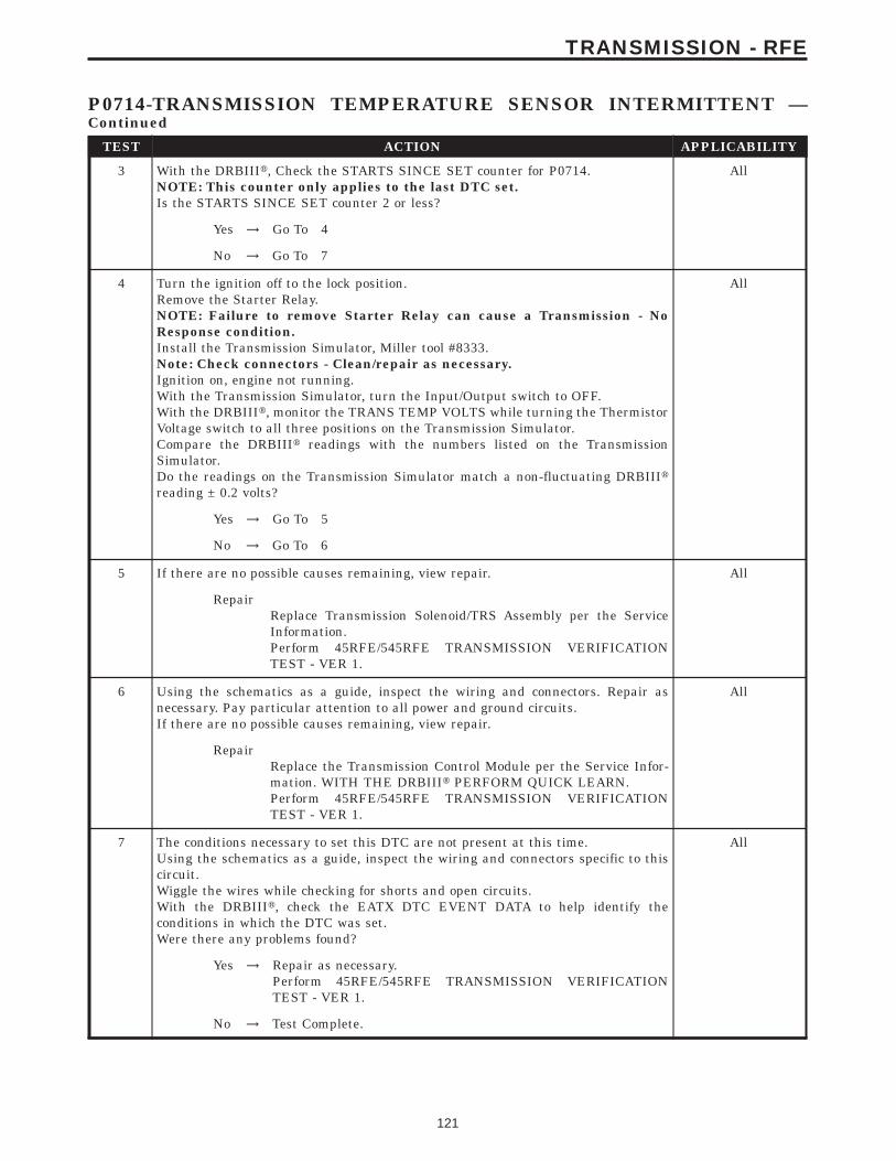
TEST ACTION APPLICABILITY
3 With the DRBIIIt, Check the STARTS SINCE SET counter for P0714.NOTE: This counter only applies to the last DTC set.Is the STARTS SINCE SET counter 2 or less?
All
Yes → Go To 4
No → Go To 7
4 Turn the ignition off to the lock position.Remove the Starter Relay.NOTE: Failure to remove Starter Relay can cause a Transmission - NoResponse condition.Install the Transmission Simulator, Miller tool #8333.Note: Check connectors - Clean/repair as necessary.Ignition on, engine not running.With the Transmission Simulator, turn the Input/Output switch to OFF.With the DRBIIIt, monitor the TRANS TEMP VOLTS while turning the ThermistorVoltage switch to all three positions on the Transmission Simulator.Compare the DRBIIIt readings with the numbers listed on the TransmissionSimulator.Do the readings on the Transmission Simulator match a non-fluctuating DRBIIItreading ± 0.2 volts?
All
Yes → Go To 5
No → Go To 6
5 If there are no possible causes remaining, view repair. All
RepairReplace Transmission Solenoid/TRS Assembly per the ServiceInformation.Perform 45RFE/545RFE TRANSMISSION VERIFICATIONTEST - VER 1.
6 Using the schematics as a guide, inspect the wiring and connectors. Repair asnecessary. Pay particular attention to all power and ground circuits.If there are no possible causes remaining, view repair.
All
RepairReplace the Transmission Control Module per the Service Infor-mation. WITH THE DRBIIIt PERFORM QUICK LEARN.Perform 45RFE/545RFE TRANSMISSION VERIFICATIONTEST - VER 1.
7 The conditions necessary to set this DTC are not present at this time.Using the schematics as a guide, inspect the wiring and connectors specific to thiscircuit.Wiggle the wires while checking for shorts and open circuits.With the DRBIIIt, check the EATX DTC EVENT DATA to help identify theconditions in which the DTC was set.Were there any problems found?
All
Yes → Repair as necessary.Perform 45RFE/545RFE TRANSMISSION VERIFICATIONTEST - VER 1.
No → Test Complete.
121
TRANSMISSION - RFE
P0714-TRANSMISSION TEMPERATURE SENSOR INTERMITTENT —Continued
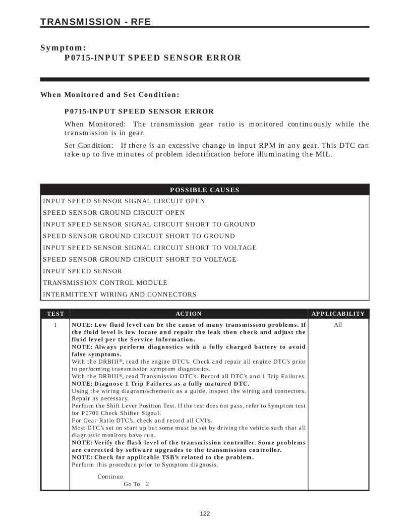
Symptom:P0715-INPUT SPEED SENSOR ERROR
When Monitored and Set Condition:
P0715-INPUT SPEED SENSOR ERROR
When Monitored: The transmission gear ratio is monitored continuously while thetransmission is in gear.
Set Condition: If there is an excessive change in input RPM in any gear. This DTC cantake up to five minutes of problem identification before illuminating the MIL.
POSSIBLE CAUSES
INPUT SPEED SENSOR SIGNAL CIRCUIT OPEN
SPEED SENSOR GROUND CIRCUIT OPEN
INPUT SPEED SENSOR SIGNAL CIRCUIT SHORT TO GROUND
SPEED SENSOR GROUND CIRCUIT SHORT TO GROUND
INPUT SPEED SENSOR SIGNAL CIRCUIT SHORT TO VOLTAGE
SPEED SENSOR GROUND CIRCUIT SHORT TO VOLTAGE
INPUT SPEED SENSOR
TRANSMISSION CONTROL MODULE
INTERMITTENT WIRING AND CONNECTORS
TEST ACTION APPLICABILITY
1 NOTE: Low fluid level can be the cause of many transmission problems. Ifthe fluid level is low locate and repair the leak then check and adjust thefluid level per the Service Information.NOTE: Always perform diagnostics with a fully charged battery to avoidfalse symptoms.With the DRBIIIt, read the engine DTC’s. Check and repair all engine DTC’s priorto performing transmission symptom diagnostics.With the DRBIIIt, read Transmission DTC’s. Record all DTC’s and 1 Trip Failures.NOTE: Diagnose 1 Trip Failures as a fully matured DTC.Using the wiring diagram/schematic as a guide, inspect the wiring and connectors.Repair as necessary.Perform the Shift Lever Position Test. If the test does not pass, refer to Symptom testfor P0706 Check Shifter Signal.For Gear Ratio DTC’s, check and record all CVI’s.Most DTC’s set on start up but some must be set by driving the vehicle such that alldiagnostic monitors have run.NOTE: Verify the flash level of the transmission controller. Some problemsare corrected by software upgrades to the transmission controller.NOTE: Check for applicable TSB’s related to the problem.Perform this procedure prior to Symptom diagnosis.
All
ContinueGo To 2
122
TRANSMISSION - RFE
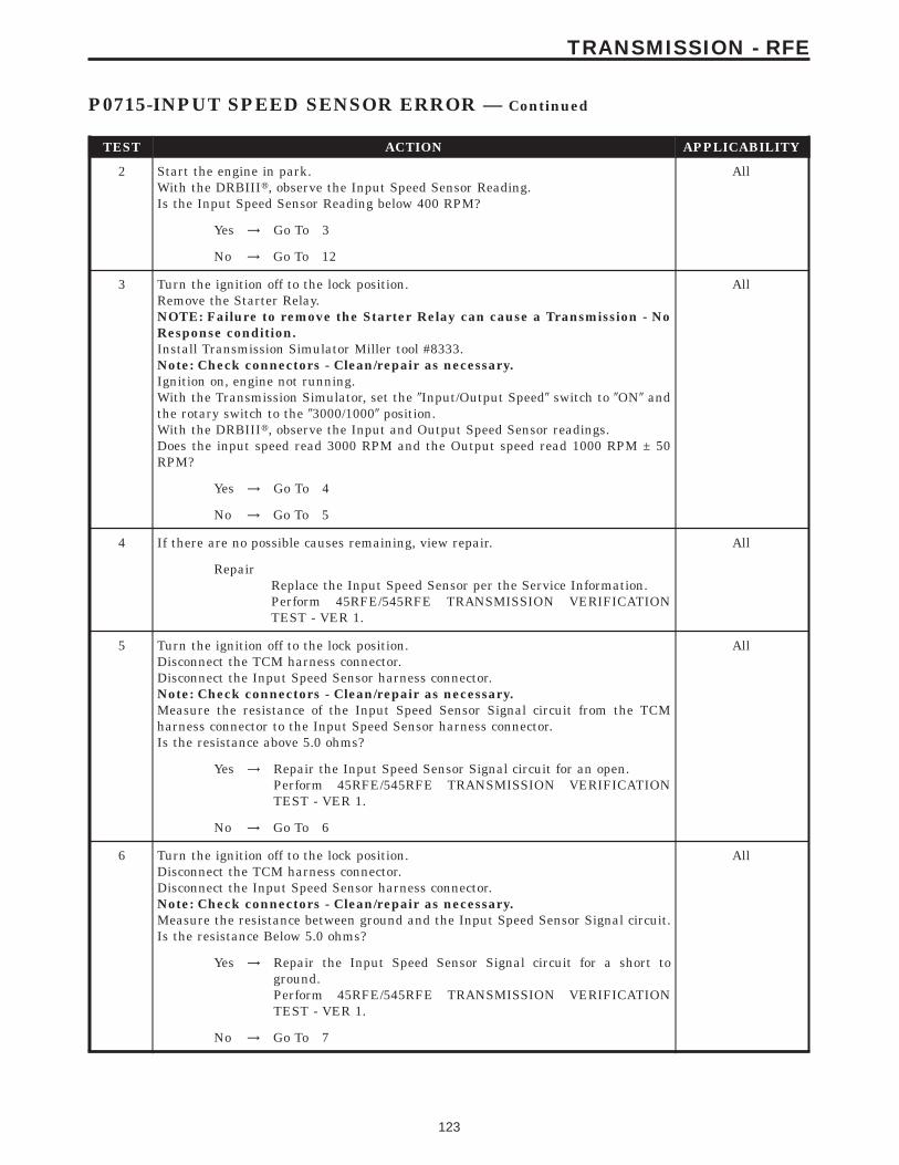
TEST ACTION APPLICABILITY
2 Start the engine in park.With the DRBIIIt, observe the Input Speed Sensor Reading.Is the Input Speed Sensor Reading below 400 RPM?
All
Yes → Go To 3
No → Go To 12
3 Turn the ignition off to the lock position.Remove the Starter Relay.NOTE: Failure to remove the Starter Relay can cause a Transmission - NoResponse condition.Install Transmission Simulator Miller tool #8333.Note: Check connectors - Clean/repair as necessary.Ignition on, engine not running.With the Transmission Simulator, set the 9Input/Output Speed9 switch to 9ON9 andthe rotary switch to the 93000/10009 position.With the DRBIIIt, observe the Input and Output Speed Sensor readings.Does the input speed read 3000 RPM and the Output speed read 1000 RPM ± 50RPM?
All
Yes → Go To 4
No → Go To 5
4 If there are no possible causes remaining, view repair. All
RepairReplace the Input Speed Sensor per the Service Information.Perform 45RFE/545RFE TRANSMISSION VERIFICATIONTEST - VER 1.
5 Turn the ignition off to the lock position.Disconnect the TCM harness connector.Disconnect the Input Speed Sensor harness connector.Note: Check connectors - Clean/repair as necessary.Measure the resistance of the Input Speed Sensor Signal circuit from the TCMharness connector to the Input Speed Sensor harness connector.Is the resistance above 5.0 ohms?
All
Yes → Repair the Input Speed Sensor Signal circuit for an open.Perform 45RFE/545RFE TRANSMISSION VERIFICATIONTEST - VER 1.
No → Go To 6
6 Turn the ignition off to the lock position.Disconnect the TCM harness connector.Disconnect the Input Speed Sensor harness connector.Note: Check connectors - Clean/repair as necessary.Measure the resistance between ground and the Input Speed Sensor Signal circuit.Is the resistance Below 5.0 ohms?
All
Yes → Repair the Input Speed Sensor Signal circuit for a short toground.Perform 45RFE/545RFE TRANSMISSION VERIFICATIONTEST - VER 1.
No → Go To 7
123
TRANSMISSION - RFE
P0715-INPUT SPEED SENSOR ERROR — Continued
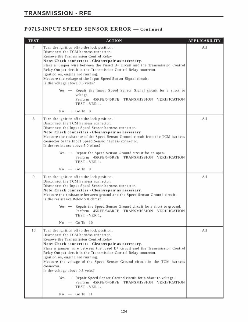
TEST ACTION APPLICABILITY
7 Turn the ignition off to the lock position.Disconnect the TCM harness connector.Remove the Transmission Control Relay.Note: Check connectors - Clean/repair as necessary.Place a jumper wire between the Fused B+ circuit and the Transmission ControlRelay Output circuit in the Transmission Control Relay connector.Ignition on, engine not running.Measure the voltage of the Input Speed Sensor Signal circuit.Is the voltage above 0.5 volts?
All
Yes → Repair the Input Speed Sensor Signal circuit for a short tovoltage.Perform 45RFE/545RFE TRANSMISSION VERIFICATIONTEST - VER 1.
No → Go To 8
8 Turn the ignition off to the lock position.Disconnect the TCM harness connector.Disconnect the Input Speed Sensor harness connector.Note: Check connectors - Clean/repair as necessary.Measure the resistance of the Speed Sensor Ground circuit from the TCM harnessconnector to the Input Speed Sensor harness connector.Is the resistance above 5.0 ohms?
All
Yes → Repair the Speed Sensor Ground circuit for an open.Perform 45RFE/545RFE TRANSMISSION VERIFICATIONTEST - VER 1.
No → Go To 9
9 Turn the ignition off to the lock position.Disconnect the TCM harness connector.Disconnect the Input Speed Sensor harness connector.Note: Check connectors - Clean/repair as necessary.Measure the resistance between ground and the Speed Sensor Ground circuit.Is the resistance Below 5.0 ohms?
All
Yes → Repair the Speed Sensor Ground circuit for a short to ground.Perform 45RFE/545RFE TRANSMISSION VERIFICATIONTEST - VER 1.
No → Go To 10
10 Turn the ignition off to the lock position.Disconnect the TCM harness connector.Remove the Transmission Control Relay.Note: Check connectors - Clean/repair as necessary.Place a jumper wire between the fused B+ circuit and the Transmission ControlRelay Output circuit in the Transmission Control Relay connector.Ignition on, engine not running.Measure the voltage of the Speed Sensor Ground circuit in the TCM harnessconnector.Is the voltage above 0.5 volts?
All
Yes → Repair Speed Sensor Ground circuit for a short to voltage.Perform 45RFE/545RFE TRANSMISSION VERIFICATIONTEST - VER 1.
No → Go To 11
124
TRANSMISSION - RFE
P0715-INPUT SPEED SENSOR ERROR — Continued

TEST ACTION APPLICABILITY
11 Using the schematics as a guide, inspect the wiring and connectors. Repair asnecessary. Pay particular attention to all power and ground circuits.If there are no possible causes remaining, view repair.
All
RepairReplace the Transmission Control Module per the Service Infor-mation. WITH THE DRBIIIt PERFORM QUICK LEARN.Perform 45RFE/545RFE TRANSMISSION VERIFICATIONTEST - VER 1.
12 The conditions necessary to set this DTC are not present at this time.Using the schematics as a guide, inspect the wiring and connectors specific to thiscircuit.Wiggle the wires while checking for shorts and open circuits.With the DRBIIIt, check the EATX DTC EVENT DATA to help identify theconditions in which the DTC was set.Were there any problems found?
All
Yes → Repair as necessary.Perform 45RFE/545RFE TRANSMISSION VERIFICATIONTEST - VER 1.
No → Test Complete.
125
TRANSMISSION - RFE
P0715-INPUT SPEED SENSOR ERROR — Continued

Symptom:P0720-OUTPUT SPEED SENSOR ERROR
When Monitored and Set Condition:
P0720-OUTPUT SPEED SENSOR ERROR
When Monitored: The transmission gear ratio is monitored continuously while thetransmission is in gear.
Set Condition: If there is an excessive change in output RPM in any gear. This DTC cantake up to five minutes of problem identification before illuminating the MIL.
POSSIBLE CAUSES
OUTPUT SPEED SENSOR SIGNAL CIRCUIT OPEN
SPEED SENSOR GROUND CIRCUIT OPEN
OUTPUT SPEED SENSOR SIGNAL CIRCUIT SHORT TO GROUND
SPEED SENSOR GROUND CIRCUIT SHORT TO GROUND
OUTPUT SPEED SENSOR SIGNAL CIRCUIT SHORT TO VOLTAGE
SPEED SENSOR GROUND CIRCUIT SHORT TO VOLTAGE
OUTPUT SPEED SENSOR
TRANSMISSION CONTROL MODULE
INTERMITTENT WIRING AND CONNECTORS
TEST ACTION APPLICABILITY
1 NOTE: Low fluid level can be the cause of many transmission problems. Ifthe fluid level is low locate and repair the leak then check and adjust thefluid level per the Service Information.NOTE: Always perform diagnostics with a fully charged battery to avoidfalse symptoms.With the DRBIIIt, read the engine DTC’s. Check and repair all engine DTC’s priorto performing transmission symptom diagnostics.With the DRBIIIt, read Transmission DTC’s. Record all DTC’s and 1 Trip Failures.NOTE: Diagnose 1 Trip Failures as a fully matured DTC.Using the wiring diagram/schematic as a guide, inspect the wiring and connectors.Repair as necessary.Perform the Shift Lever Position Test. If the test does not pass, refer to Symptom testfor P0706 Check Shifter Signal.For Gear Ratio DTC’s, check and record all CVI’s.Most DTC’s set on start up but some must be set by driving the vehicle such that alldiagnostic monitors have run.NOTE: Verify the flash level of the transmission controller. Some problemsare corrected by software upgrades to the transmission controller.NOTE: Check for applicable TSB’s related to the problem.Perform this procedure prior to Symptom diagnosis.
All
ContinueGo To 2
126
TRANSMISSION - RFE
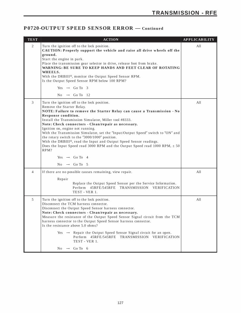
TEST ACTION APPLICABILITY
2 Turn the ignition off to the lock position.CAUTION: Properly support the vehicle and raise all drive wheels off theground.Start the engine in park.Place the transmission gear selector in drive, release foot from brake.WARNING: BE SURE TO KEEP HANDS AND FEET CLEAR OF ROTATINGWHEELS.With the DRBIIIt, monitor the Output Speed Sensor RPM.Is the Output Speed Sensor RPM below 100 RPM?
All
Yes → Go To 3
No → Go To 12
3 Turn the ignition off to the lock position.Remove the Starter Relay.NOTE: Failure to remove the Starter Relay can cause a Transmission - NoResponse condition.Install the Transmission Simulator, Miller tool #8333.Note: Check connectors - Clean/repair as necessary.Ignition on, engine not running.With the Transmission Simulator, set the 9Input/Output Speed9 switch to 9ON9 andthe rotary switch to the 93000/10009 position.With the DRBIIIt, read the Input and Output Speed Sensor readings.Does the Input Speed read 3000 RPM and the Output Speed read 1000 RPM, ± 50RPM?
All
Yes → Go To 4
No → Go To 5
4 If there are no possible causes remaining, view repair. All
RepairReplace the Output Speed Sensor per the Service Information.Perform 45RFE/545RFE TRANSMISSION VERIFICATIONTEST - VER 1.
5 Turn the ignition off to the lock position.Disconnect the TCM harness connector.Disconnect the Output Speed Sensor harness connector.Note: Check connectors - Clean/repair as necessary.Measure the resistance of the Output Speed Sensor Signal circuit from the TCMharness connector to the Output Speed Sensor harness connector.Is the resistance above 5.0 ohms?
All
Yes → Repair the Output Speed Sensor Signal circuit for an open.Perform 45RFE/545RFE TRANSMISSION VERIFICATIONTEST - VER 1.
No → Go To 6
127
TRANSMISSION - RFE
P0720-OUTPUT SPEED SENSOR ERROR — Continued
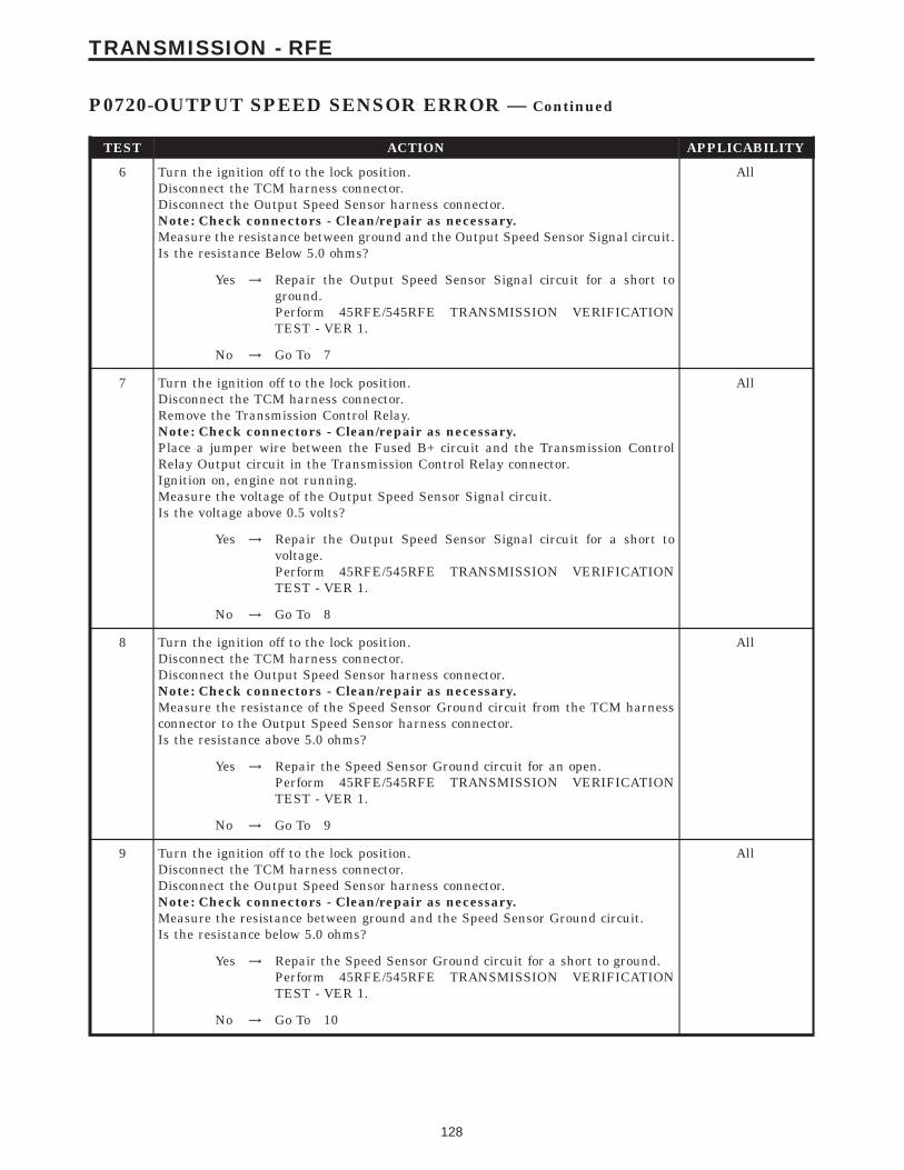
TEST ACTION APPLICABILITY
6 Turn the ignition off to the lock position.Disconnect the TCM harness connector.Disconnect the Output Speed Sensor harness connector.Note: Check connectors - Clean/repair as necessary.Measure the resistance between ground and the Output Speed Sensor Signal circuit.Is the resistance Below 5.0 ohms?
All
Yes → Repair the Output Speed Sensor Signal circuit for a short toground.Perform 45RFE/545RFE TRANSMISSION VERIFICATIONTEST - VER 1.
No → Go To 7
7 Turn the ignition off to the lock position.Disconnect the TCM harness connector.Remove the Transmission Control Relay.Note: Check connectors - Clean/repair as necessary.Place a jumper wire between the Fused B+ circuit and the Transmission ControlRelay Output circuit in the Transmission Control Relay connector.Ignition on, engine not running.Measure the voltage of the Output Speed Sensor Signal circuit.Is the voltage above 0.5 volts?
All
Yes → Repair the Output Speed Sensor Signal circuit for a short tovoltage.Perform 45RFE/545RFE TRANSMISSION VERIFICATIONTEST - VER 1.
No → Go To 8
8 Turn the ignition off to the lock position.Disconnect the TCM harness connector.Disconnect the Output Speed Sensor harness connector.Note: Check connectors - Clean/repair as necessary.Measure the resistance of the Speed Sensor Ground circuit from the TCM harnessconnector to the Output Speed Sensor harness connector.Is the resistance above 5.0 ohms?
All
Yes → Repair the Speed Sensor Ground circuit for an open.Perform 45RFE/545RFE TRANSMISSION VERIFICATIONTEST - VER 1.
No → Go To 9
9 Turn the ignition off to the lock position.Disconnect the TCM harness connector.Disconnect the Output Speed Sensor harness connector.Note: Check connectors - Clean/repair as necessary.Measure the resistance between ground and the Speed Sensor Ground circuit.Is the resistance below 5.0 ohms?
All
Yes → Repair the Speed Sensor Ground circuit for a short to ground.Perform 45RFE/545RFE TRANSMISSION VERIFICATIONTEST - VER 1.
No → Go To 10
128
TRANSMISSION - RFE
P0720-OUTPUT SPEED SENSOR ERROR — Continued
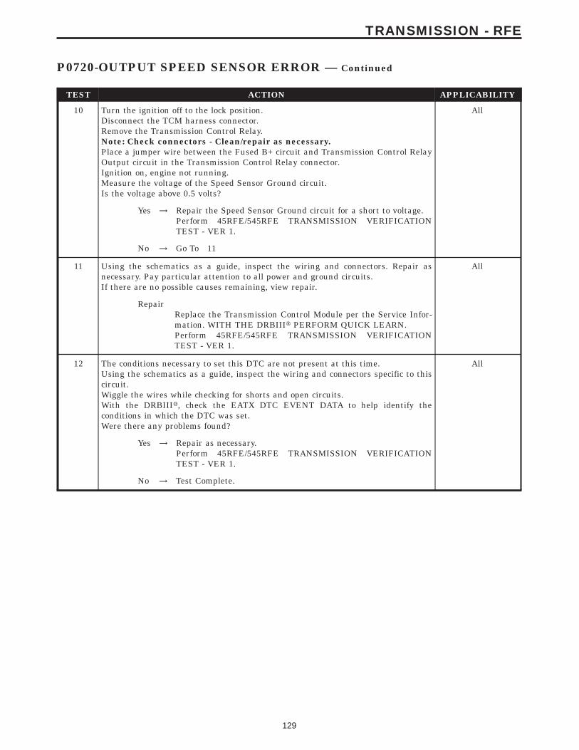
TEST ACTION APPLICABILITY
10 Turn the ignition off to the lock position.Disconnect the TCM harness connector.Remove the Transmission Control Relay.Note: Check connectors - Clean/repair as necessary.Place a jumper wire between the Fused B+ circuit and Transmission Control RelayOutput circuit in the Transmission Control Relay connector.Ignition on, engine not running.Measure the voltage of the Speed Sensor Ground circuit.Is the voltage above 0.5 volts?
All
Yes → Repair the Speed Sensor Ground circuit for a short to voltage.Perform 45RFE/545RFE TRANSMISSION VERIFICATIONTEST - VER 1.
No → Go To 11
11 Using the schematics as a guide, inspect the wiring and connectors. Repair asnecessary. Pay particular attention to all power and ground circuits.If there are no possible causes remaining, view repair.
All
RepairReplace the Transmission Control Module per the Service Infor-mation. WITH THE DRBIIIt PERFORM QUICK LEARN.Perform 45RFE/545RFE TRANSMISSION VERIFICATIONTEST - VER 1.
12 The conditions necessary to set this DTC are not present at this time.Using the schematics as a guide, inspect the wiring and connectors specific to thiscircuit.Wiggle the wires while checking for shorts and open circuits.With the DRBIIIt, check the EATX DTC EVENT DATA to help identify theconditions in which the DTC was set.Were there any problems found?
All
Yes → Repair as necessary.Perform 45RFE/545RFE TRANSMISSION VERIFICATIONTEST - VER 1.
No → Test Complete.
129
TRANSMISSION - RFE
P0720-OUTPUT SPEED SENSOR ERROR — Continued
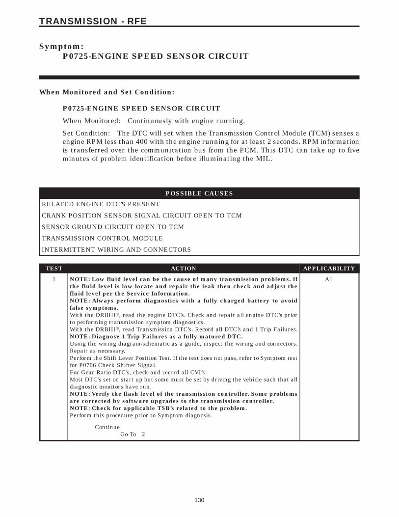
Symptom:P0725-ENGINE SPEED SENSOR CIRCUIT
When Monitored and Set Condition:
P0725-ENGINE SPEED SENSOR CIRCUIT
When Monitored: Continuously with engine running.
Set Condition: The DTC will set when the Transmission Control Module (TCM) senses aengine RPM less than 400 with the engine running for at least 2 seconds. RPM informationis transferred over the communication bus from the PCM. This DTC can take up to fiveminutes of problem identification before illuminating the MIL.
POSSIBLE CAUSES
RELATED ENGINE DTC’S PRESENT
CRANK POSITION SENSOR SIGNAL CIRCUIT OPEN TO TCM
SENSOR GROUND CIRCUIT OPEN TO TCM
TRANSMISSION CONTROL MODULE
INTERMITTENT WIRING AND CONNECTORS
TEST ACTION APPLICABILITY
1 NOTE: Low fluid level can be the cause of many transmission problems. Ifthe fluid level is low locate and repair the leak then check and adjust thefluid level per the Service Information.NOTE: Always perform diagnostics with a fully charged battery to avoidfalse symptoms.With the DRBIIIt, read the engine DTC’s. Check and repair all engine DTC’s priorto performing transmission symptom diagnostics.With the DRBIIIt, read Transmission DTC’s. Record all DTC’s and 1 Trip Failures.NOTE: Diagnose 1 Trip Failures as a fully matured DTC.Using the wiring diagram/schematic as a guide, inspect the wiring and connectors.Repair as necessary.Perform the Shift Lever Position Test. If the test does not pass, refer to Symptom testfor P0706 Check Shifter Signal.For Gear Ratio DTC’s, check and record all CVI’s.Most DTC’s set on start up but some must be set by driving the vehicle such that alldiagnostic monitors have run.NOTE: Verify the flash level of the transmission controller. Some problemsare corrected by software upgrades to the transmission controller.NOTE: Check for applicable TSB’s related to the problem.Perform this procedure prior to Symptom diagnosis.
All
ContinueGo To 2
130
TRANSMISSION - RFE
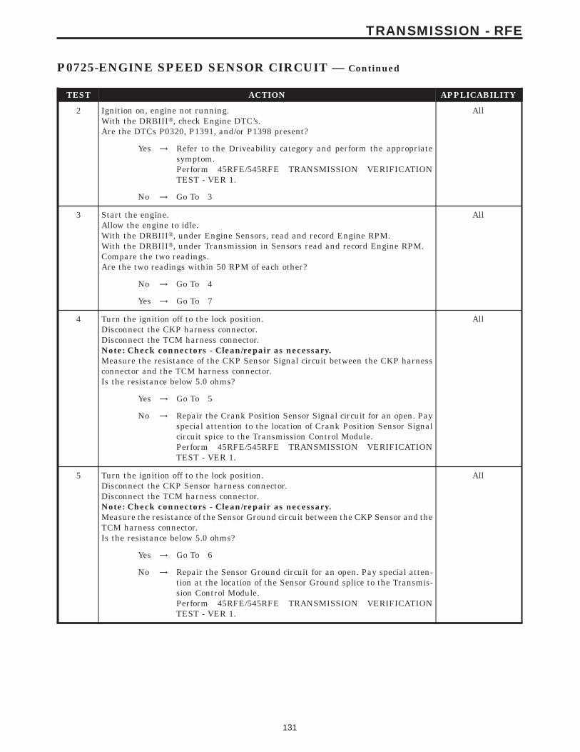
TEST ACTION APPLICABILITY
2 Ignition on, engine not running.With the DRBIIIt, check Engine DTC’s.Are the DTCs P0320, P1391, and/or P1398 present?
All
Yes → Refer to the Driveability category and perform the appropriatesymptom.Perform 45RFE/545RFE TRANSMISSION VERIFICATIONTEST - VER 1.
No → Go To 3
3 Start the engine.Allow the engine to idle.With the DRBIIIt, under Engine Sensors, read and record Engine RPM.With the DRBIIIt, under Transmission in Sensors read and record Engine RPM.Compare the two readings.Are the two readings within 50 RPM of each other?
All
No → Go To 4
Yes → Go To 7
4 Turn the ignition off to the lock position.Disconnect the CKP harness connector.Disconnect the TCM harness connector.Note: Check connectors - Clean/repair as necessary.Measure the resistance of the CKP Sensor Signal circuit between the CKP harnessconnector and the TCM harness connector.Is the resistance below 5.0 ohms?
All
Yes → Go To 5
No → Repair the Crank Position Sensor Signal circuit for an open. Payspecial attention to the location of Crank Position Sensor Signalcircuit spice to the Transmission Control Module.Perform 45RFE/545RFE TRANSMISSION VERIFICATIONTEST - VER 1.
5 Turn the ignition off to the lock position.Disconnect the CKP Sensor harness connector.Disconnect the TCM harness connector.Note: Check connectors - Clean/repair as necessary.Measure the resistance of the Sensor Ground circuit between the CKP Sensor and theTCM harness connector.Is the resistance below 5.0 ohms?
All
Yes → Go To 6
No → Repair the Sensor Ground circuit for an open. Pay special atten-tion at the location of the Sensor Ground splice to the Transmis-sion Control Module.Perform 45RFE/545RFE TRANSMISSION VERIFICATIONTEST - VER 1.
131
TRANSMISSION - RFE
P0725-ENGINE SPEED SENSOR CIRCUIT — Continued
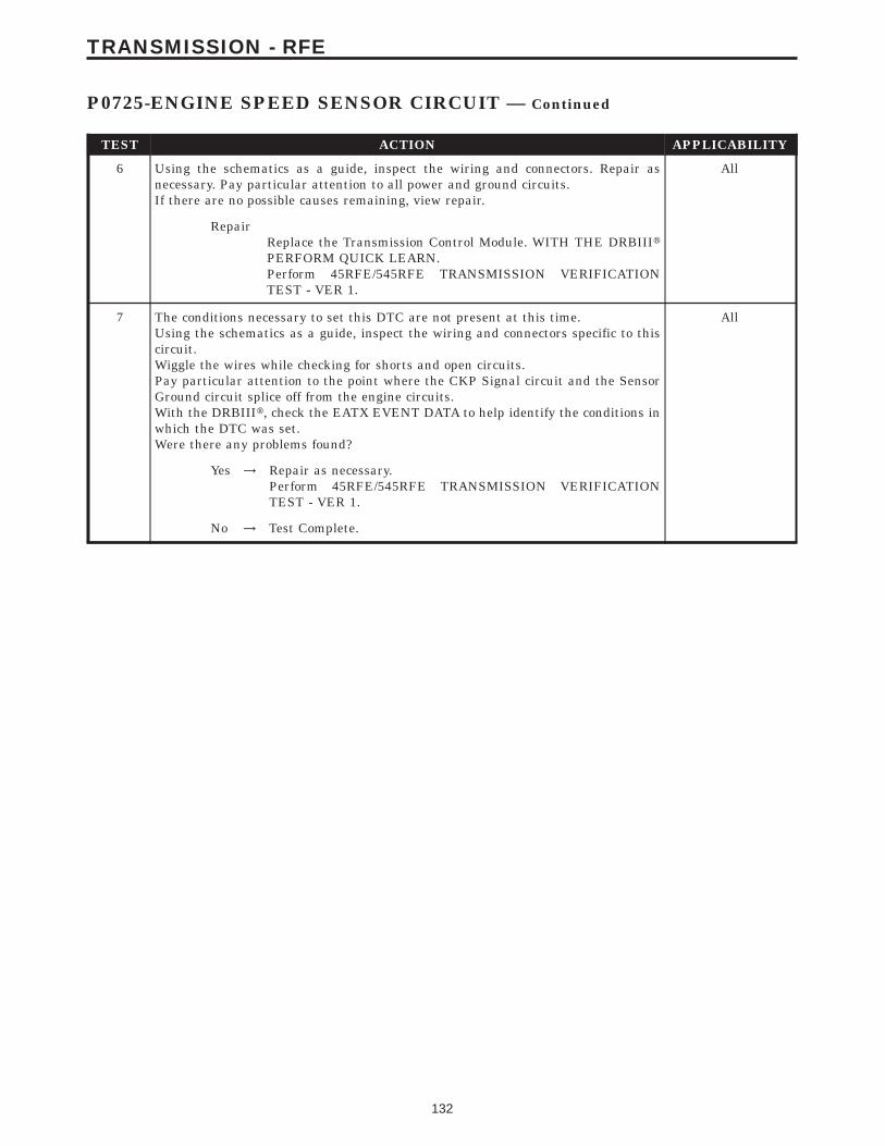
TEST ACTION APPLICABILITY
6 Using the schematics as a guide, inspect the wiring and connectors. Repair asnecessary. Pay particular attention to all power and ground circuits.If there are no possible causes remaining, view repair.
All
RepairReplace the Transmission Control Module. WITH THE DRBIIItPERFORM QUICK LEARN.Perform 45RFE/545RFE TRANSMISSION VERIFICATIONTEST - VER 1.
7 The conditions necessary to set this DTC are not present at this time.Using the schematics as a guide, inspect the wiring and connectors specific to thiscircuit.Wiggle the wires while checking for shorts and open circuits.Pay particular attention to the point where the CKP Signal circuit and the SensorGround circuit splice off from the engine circuits.With the DRBIIIt, check the EATX EVENT DATA to help identify the conditions inwhich the DTC was set.Were there any problems found?
All
Yes → Repair as necessary.Perform 45RFE/545RFE TRANSMISSION VERIFICATIONTEST - VER 1.
No → Test Complete.
132
TRANSMISSION - RFE
P0725-ENGINE SPEED SENSOR CIRCUIT — Continued
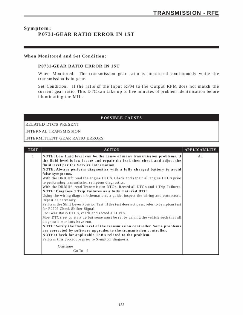
Symptom:P0731-GEAR RATIO ERROR IN 1ST
When Monitored and Set Condition:
P0731-GEAR RATIO ERROR IN 1ST
When Monitored: The transmission gear ratio is monitored continuously while thetransmission is in gear.
Set Condition: If the ratio of the Input RPM to the Output RPM does not match thecurrent gear ratio. This DTC can take up to five minutes of problem identification beforeilluminating the MIL.
POSSIBLE CAUSES
RELATED DTC’S PRESENT
INTERNAL TRANSMISSION
INTERMITTENT GEAR RATIO ERRORS
TEST ACTION APPLICABILITY
1 NOTE: Low fluid level can be the cause of many transmission problems. Ifthe fluid level is low locate and repair the leak then check and adjust thefluid level per the Service Information.NOTE: Always perform diagnostics with a fully charged battery to avoidfalse symptoms.With the DRBIIIt, read the engine DTC’s. Check and repair all engine DTC’s priorto performing transmission symptom diagnostics.With the DRBIIIt, read Transmission DTC’s. Record all DTC’s and 1 Trip Failures.NOTE: Diagnose 1 Trip Failures as a fully matured DTC.Using the wiring diagram/schematic as a guide, inspect the wiring and connectors.Repair as necessary.Perform the Shift Lever Position Test. If the test does not pass, refer to Symptom testfor P0706 Check Shifter Signal.For Gear Ratio DTC’s, check and record all CVI’s.Most DTC’s set on start up but some must be set by driving the vehicle such that alldiagnostic monitors have run.NOTE: Verify the flash level of the transmission controller. Some problemsare corrected by software upgrades to the transmission controller.NOTE: Check for applicable TSB’s related to the problem.Perform this procedure prior to Symptom diagnosis.
All
ContinueGo To 2
133
TRANSMISSION - RFE
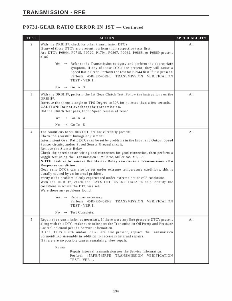
TEST ACTION APPLICABILITY
2 With the DRBIIIt, check for other transmission DTC’sIf any of these DTC’s are present, perform their respective tests first.Are DTC’s P0944, P0715, P0720, P1794, P0867, P0932, P0868, or P0869 presentalso?
All
Yes → Refer to the Transmission category and perform the appropriatesymptom. If any of these DTCs are present, they will cause aSpeed Ratio Error. Perform the test for P0944 first if it is present.Perform 45RFE/545RFE TRANSMISSION VERIFICATIONTEST - VER 1.
No → Go To 3
3 With the DRBIIIt, perform the 1st Gear Clutch Test. Follow the instructions on theDRBIIIt.Increase the throttle angle or TPS Degree to 30°, for no more than a few seconds.CAUTION: Do not overheat the transmission.Did the Clutch Test pass, Input Speed remain at zero?
All
Yes → Go To 4
No → Go To 5
4 The conditions to set this DTC are not currently present.Check the gearshift linkage adjustment.Intermittent Gear Ratio DTCs can be set by problems in the Input and Output SpeedSensor circuits and/or Speed Sensor Ground circuit.Remove the Starter Relay.Check the speed sensor wiring and connectors for good connection, then perform awiggle test using the Transmission Simulator, Miller tool # 8333.NOTE: Failure to remove the Starter Relay can cause a Transmission - NoResponse condition.Gear ratio DTC’s can also be set under extreme temperature conditions, this isusually caused by an internal problem.Verify if the problem is only experienced under extreme hot or cold conditions.With the DRBIIIt, check the EATX DTC EVENT DATA to help identify theconditions in which the DTC was set.Were there any problems found.
All
Yes → Repair as necessary.Perform 45RFE/545RFE TRANSMISSION VERIFICATIONTEST - VER 1.
No → Test Complete.
5 Repair the transmission as necessary. If there were any line pressure DTC’s presentalong with this DTC, make sure to inspect the Transmission Oil Pump and PressureControl Solenoid per the Service Information.If the DTC’s P0876 and/or P0875 are also present, replace the TransmissionSolenoid/TRS Assembly in addition to necessary internal repairs.If there are no possible causes remaining, view repair.
All
RepairRepair internal transmission per the Service Information.Perform 45RFE/545RFE TRANSMISSION VERIFICATIONTEST - VER 1.
134
TRANSMISSION - RFE
P0731-GEAR RATIO ERROR IN 1ST — Continued

Symptom:P0732-GEAR RATIO ERROR IN 2ND
When Monitored and Set Condition:
P0732-GEAR RATIO ERROR IN 2ND
When Monitored: The transmission gear ratio is monitored continuously while thetransmission is in gear.
Set Condition: If the ratio of the Input RPM to the Output RPM does not match thecurrent gear ratio. This DTC can take up to five minutes of problem identification beforeilluminating the MIL.
POSSIBLE CAUSES
RELATED DTC’S PRESENT
RELATED PRESSURE SWITCH DTC’S PRESENT
INTERNAL TRANSMISSION
INTERMITTENT GEAR RATIO ERRORS
TEST ACTION APPLICABILITY
1 NOTE: Low fluid level can be the cause of many transmission problems. Ifthe fluid level is low locate and repair the leak then check and adjust thefluid level per the Service Information.NOTE: Always perform diagnostics with a fully charged battery to avoidfalse symptoms.With the DRBIIIt, read the engine DTC’s. Check and repair all engine DTC’s priorto performing transmission symptom diagnostics.With the DRBIIIt, read Transmission DTC’s. Record all DTC’s and 1 Trip Failures.NOTE: Diagnose 1 Trip Failures as a fully matured DTC.Using the wiring diagram/schematic as a guide, inspect the wiring and connectors.Repair as necessary.Perform the Shift Lever Position Test. If the test does not pass, refer to Symptom testfor P0706 Check Shifter Signal.For Gear Ratio DTC’s, check and record all CVI’s.Most DTC’s set on start up but some must be set by driving the vehicle such that alldiagnostic monitors have run.NOTE: Verify the flash level of the transmission controller. Some problemsare corrected by software upgrades to the transmission controller.NOTE: Check for applicable TSB’s related to the problem.Perform this procedure prior to Symptom diagnosis.
All
ContinueGo To 2
135
TRANSMISSION - RFE

TEST ACTION APPLICABILITY
2 With the DRBIIIt, check for other transmission DTC’sIf any of these DTC’s are present, perform their respective tests first.Are DTC’s P0944, P0715, P0720, P1794, P0867, P0932, P0868, and/ or P0869 presentalso?
All
Yes → Refer to the Transmission category and perform the appropriatesymptom. If any of these DTCs are present, they will cause aSpeed Ratio Error. Perform the test for P0944 first if it is present.Perform 45RFE/545RFE TRANSMISSION VERIFICATIONTEST - VER 1.
No → Go To 3
3 With the DRBIIIt, perform the 2nd Gear Clutch Test. Follow the instructions on theDRBIIIt.Increase the throttle angle, TPS Degree to 30° for no more than a few seconds.CAUTION: Do not overheat the transmission.Did the clutch test pass, Input speed remain at zero?
All
Yes → Go To 4
No → Go To 5
4 The conditions to set this DTC are not currently present.Check the gearshift linkage adjustment.Intermittent gear ratio DTCs can be set by problems in the Input and Output SpeedSensor circuits and/or Speed Sensor Ground circuit.Remove the Starter Relay.NOTE: Failure to remove the Starter Relay can cause a TCM - No Responsecondition.Check the speed sensor wiring and connectors for good connection, then perform awiggle test using the Transmission Simulator, Miller tool # 8333.Gear ratio DTC’s can also be set under extreme temperature conditions, this isusually caused by an internal problem.Verify if the problem is only experienced under extreme hot or cold conditions.With the DRBIIIt, check the EATX DTC EVENT DATA to help identify theconditions in which the DTC was set.Were there any problems found?
All
Yes → Repair as necessary.Perform 45RFE/545RFE TRANSMISSION VERIFICATIONTEST - VER 1.
No → Test Complete.
5 With the DRBIIIt, check for other transmission DTC’sIs a DTC P0845 2C Hydraulic Pressure Switch and/or P0846 2C Pressure Switchpresent also?
All
Yes → Repair the Transmission or Solenoid/TRS assembly per the Ser-vice Information.Perform 45RFE/545RFE TRANSMISSION VERIFICATIONTEST - VER 1.
No → Go To 6
136
TRANSMISSION - RFE
P0732-GEAR RATIO ERROR IN 2ND — Continued

TEST ACTION APPLICABILITY
6 Repair internal transmission as necessary. If any line pressure DTCs are presentalong with this DTC, make sure to inspect the Transmission Oil Pump and PressureControl Solenoid per the Service Information.If DTC’s P0846 and/or P0845 are also present, replace the Transmission Solenoid/TRS Assembly in addition to internal repairs.If there are no possible causes remaining, view repair.
All
RepairRepair internal transmission per the Service Information.Perform 45RFE/545RFE TRANSMISSION VERIFICATIONTEST - VER 1.
137
TRANSMISSION - RFE
P0732-GEAR RATIO ERROR IN 2ND — Continued
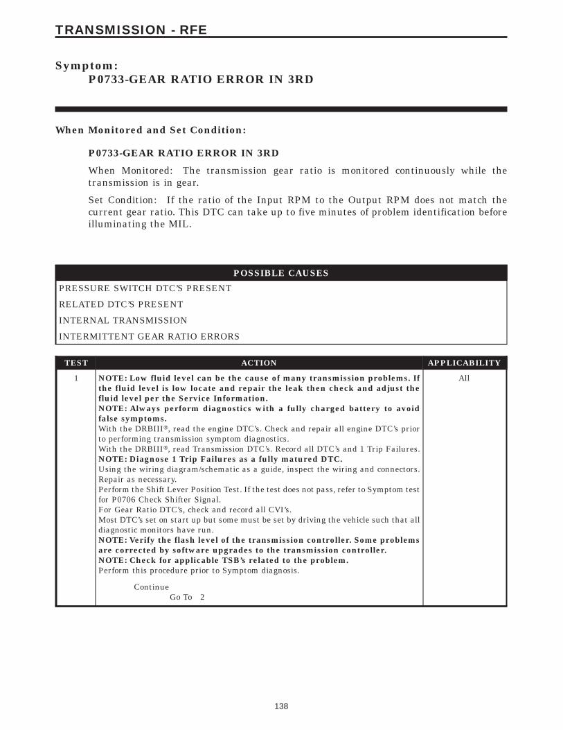
Symptom:P0733-GEAR RATIO ERROR IN 3RD
When Monitored and Set Condition:
P0733-GEAR RATIO ERROR IN 3RD
When Monitored: The transmission gear ratio is monitored continuously while thetransmission is in gear.
Set Condition: If the ratio of the Input RPM to the Output RPM does not match thecurrent gear ratio. This DTC can take up to five minutes of problem identification beforeilluminating the MIL.
POSSIBLE CAUSES
PRESSURE SWITCH DTC’S PRESENT
RELATED DTC’S PRESENT
INTERNAL TRANSMISSION
INTERMITTENT GEAR RATIO ERRORS
TEST ACTION APPLICABILITY
1 NOTE: Low fluid level can be the cause of many transmission problems. Ifthe fluid level is low locate and repair the leak then check and adjust thefluid level per the Service Information.NOTE: Always perform diagnostics with a fully charged battery to avoidfalse symptoms.With the DRBIIIt, read the engine DTC’s. Check and repair all engine DTC’s priorto performing transmission symptom diagnostics.With the DRBIIIt, read Transmission DTC’s. Record all DTC’s and 1 Trip Failures.NOTE: Diagnose 1 Trip Failures as a fully matured DTC.Using the wiring diagram/schematic as a guide, inspect the wiring and connectors.Repair as necessary.Perform the Shift Lever Position Test. If the test does not pass, refer to Symptom testfor P0706 Check Shifter Signal.For Gear Ratio DTC’s, check and record all CVI’s.Most DTC’s set on start up but some must be set by driving the vehicle such that alldiagnostic monitors have run.NOTE: Verify the flash level of the transmission controller. Some problemsare corrected by software upgrades to the transmission controller.NOTE: Check for applicable TSB’s related to the problem.Perform this procedure prior to Symptom diagnosis.
All
ContinueGo To 2
138
TRANSMISSION - RFE
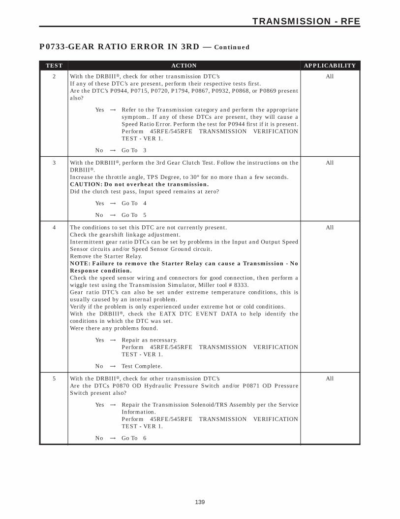
TEST ACTION APPLICABILITY
2 With the DRBIIIt, check for other transmission DTC’sIf any of these DTC’s are present, perform their respective tests first.Are the DTC’s P0944, P0715, P0720, P1794, P0867, P0932, P0868, or P0869 presentalso?
All
Yes → Refer to the Transmission category and perform the appropriatesymptom.. If any of these DTCs are present, they will cause aSpeed Ratio Error. Perform the test for P0944 first if it is present.Perform 45RFE/545RFE TRANSMISSION VERIFICATIONTEST - VER 1.
No → Go To 3
3 With the DRBIIIt, perform the 3rd Gear Clutch Test. Follow the instructions on theDRBIIIt.Increase the throttle angle, TPS Degree, to 30° for no more than a few seconds.CAUTION: Do not overheat the transmission.Did the clutch test pass, Input speed remains at zero?
All
Yes → Go To 4
No → Go To 5
4 The conditions to set this DTC are not currently present.Check the gearshift linkage adjustment.Intermittent gear ratio DTCs can be set by problems in the Input and Output SpeedSensor circuits and/or Speed Sensor Ground circuit.Remove the Starter Relay.NOTE: Failure to remove the Starter Relay can cause a Transmission - NoResponse condition.Check the speed sensor wiring and connectors for good connection, then perform awiggle test using the Transmission Simulator, Miller tool # 8333.Gear ratio DTC’s can also be set under extreme temperature conditions, this isusually caused by an internal problem.Verify if the problem is only experienced under extreme hot or cold conditions.With the DRBIIIt, check the EATX DTC EVENT DATA to help identify theconditions in which the DTC was set.Were there any problems found.
All
Yes → Repair as necessary.Perform 45RFE/545RFE TRANSMISSION VERIFICATIONTEST - VER 1.
No → Test Complete.
5 With the DRBIIIt, check for other transmission DTC’sAre the DTCs P0870 OD Hydraulic Pressure Switch and/or P0871 OD PressureSwitch present also?
All
Yes → Repair the Transmission Solenoid/TRS Assembly per the ServiceInformation.Perform 45RFE/545RFE TRANSMISSION VERIFICATIONTEST - VER 1.
No → Go To 6
139
TRANSMISSION - RFE
P0733-GEAR RATIO ERROR IN 3RD — Continued
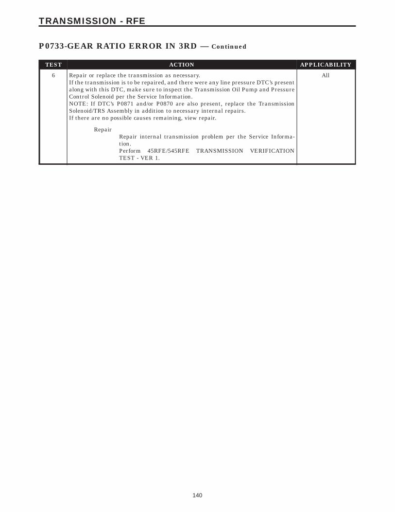
TEST ACTION APPLICABILITY
6 Repair or replace the transmission as necessary.If the transmission is to be repaired, and there were any line pressure DTC’s presentalong with this DTC, make sure to inspect the Transmission Oil Pump and PressureControl Solenoid per the Service Information.NOTE: If DTC’s P0871 and/or P0870 are also present, replace the TransmissionSolenoid/TRS Assembly in addition to necessary internal repairs.If there are no possible causes remaining, view repair.
All
RepairRepair internal transmission problem per the Service Informa-tion.Perform 45RFE/545RFE TRANSMISSION VERIFICATIONTEST - VER 1.
140
TRANSMISSION - RFE
P0733-GEAR RATIO ERROR IN 3RD — Continued

Symptom:P0734-GEAR RATIO ERROR IN 4TH
When Monitored and Set Condition:
P0734-GEAR RATIO ERROR IN 4TH
When Monitored: The transmission gear ratio is monitored continuously while thetransmission is in gear.
Set Condition: If the ratio of the Input RPM to the Output RPM does not match thecurrent gear ratio. This DTC can take up to five minutes of problem identification beforeilluminating the MIL.
POSSIBLE CAUSES
RELATED DTC’S PRESENT
RELATED PRESSURE SWITCH DTC’S PRESENT
INTERNAL TRANSMISSION
TEST ACTION APPLICABILITY
1 NOTE: Low fluid level can be the cause of many transmission problems. Ifthe fluid level is low locate and repair the leak then check and adjust thefluid level per the Service Information.NOTE: Always perform diagnostics with a fully charged battery to avoidfalse symptoms.With the DRBIIIt, read the engine DTC’s. Check and repair all engine DTC’s priorto performing transmission symptom diagnostics.With the DRBIIIt, read Transmission DTC’s. Record all DTC’s and 1 Trip Failures.NOTE: Diagnose 1 Trip Failures as a fully matured DTC.Using the wiring diagram/schematic as a guide, inspect the wiring and connectors.Repair as necessary.Perform the Shift Lever Position Test. If the test does not pass, refer to Symptom testfor P0706 Check Shifter Signal.For Gear Ratio DTC’s, check and record all CVI’s.Most DTC’s set on start up but some must be set by driving the vehicle such that alldiagnostic monitors have run.NOTE: Verify the flash level of the transmission controller. Some problemsare corrected by software upgrades to the transmission controller.NOTE: Check for applicable TSB’s related to the problem.Perform this procedure prior to Symptom diagnosis.
All
ContinueGo To 2
141
TRANSMISSION - RFE
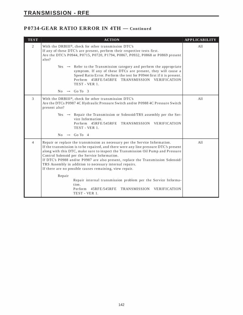
TEST ACTION APPLICABILITY
2 With the DRBIIIt, check for other transmission DTC’sIf any of these DTC’s are present, perform their respective tests first.Are the DTC’s P0944, P0715, P0720, P1794, P0867, P0932, P0868 or P0869 presentalso?
All
Yes → Refer to the Transmission category and perform the appropriatesymptom. If any of these DTCs are present, they will cause aSpeed Ratio Error. Perform the test for P0944 first if it is present.Perform 45RFE/545RFE TRANSMISSION VERIFICATIONTEST - VER 1.
No → Go To 3
3 With the DRBIIIt, check for other transmission DTC’sAre the DTCs P0987 4C Hydraulic Pressure Switch and/or P0988 4C Pressure Switchpresent also?
All
Yes → Repair the Transmission or Solenoid/TRS assembly per the Ser-vice Information.Perform 45RFE/545RFE TRANSMISSION VERIFICATIONTEST - VER 1.
No → Go To 4
4 Repair or replace the transmission as necessary per the Service Information.If the transmission is to be repaired, and there were any line pressure DTC’s presentalong with this DTC, make sure to inspect the Transmission Oil Pump and PressureControl Solenoid per the Service Information.If DTC’s P0988 and/or P0987 are also present, replace the Transmission Solenoid/TRS Assembly in addition to necessary internal repairs.If there are no possible causes remaining, view repair.
All
RepairRepair internal transmission problem per the Service Informa-tion.Perform 45RFE/545RFE TRANSMISSION VERIFICATIONTEST - VER 1.
142
TRANSMISSION - RFE
P0734-GEAR RATIO ERROR IN 4TH — Continued

Symptom:P0735-GEAR RATIO ERROR 4TH PRIME
When Monitored and Set Condition:
P0735-GEAR RATIO ERROR 4TH PRIME
When Monitored: The transmission gear ratio is monitored continuously while thetransmission is in gear.
Set Condition: If the ratio of the Input RPM to the Output RPM does not match thecurrent gear ratio. This DTC can take up to five minutes of problem identification beforeilluminating the MIL.
POSSIBLE CAUSES
RELATED DTC’S PRESENT
INTERNAL TRANSMISSION
INTERMITTENT GEAR RATIO ERRORS
TEST ACTION APPLICABILITY
1 NOTE: Low fluid level can be the cause of many transmission problems. Ifthe fluid level is low locate and repair the leak then check and adjust thefluid level per the Service Information.NOTE: Always perform diagnostics with a fully charged battery to avoidfalse symptoms.With the DRBIIIt, read the engine DTC’s. Check and repair all engine DTC’s priorto performing transmission symptom diagnostics.With the DRBIIIt, read Transmission DTC’s. Record all DTC’s and 1 Trip Failures.NOTE: Diagnose 1 Trip Failures as a fully matured DTC.Using the wiring diagram/schematic as a guide, inspect the wiring and connectors.Repair as necessary.Perform the Shift Lever Position Test. If the test does not pass, refer to Symptom testfor P0706 Check Shifter Signal.For Gear Ratio DTC’s, check and record all CVI’s.Most DTC’s set on start up but some must be set by driving the vehicle such that alldiagnostic monitors have run.NOTE: Verify the flash level of the transmission controller. Some problemsare corrected by software upgrades to the transmission controller.NOTE: Check for applicable TSB’s related to the problem.Perform this procedure prior to Symptom diagnosis.
All
ContinueGo To 2
143
TRANSMISSION - RFE
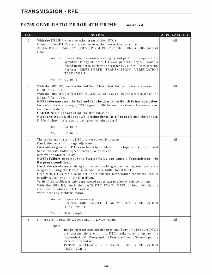
TEST ACTION APPLICABILITY
2 With the DRBIIIt, check for other transmission DTC’s.If any of these DTC’s are present, perform their respective tests first.Are the DTC’s P0944, P0715, P0720, P1794, P0867, P0932, P0868 or P0869 presentalso?
All
Yes → Refer to the Transmission category and perform the appropriatesymptom. If any of these DTCs are present, they will cause aSpeed Ratio Error. Perform the test for P0944 first if it is present.Perform 45RFE/545RFE TRANSMISSION VERIFICATIONTEST - VER 1.
No → Go To 3
3 With the DRBIIIt, perform the 2nd Gear Clutch Test. Follow the instructions on theDRBIIIt for the test.With the DRBIIIt, perform the 3rd Gear Clutch Test. Follow the instructions on theDRBIIIt for the test.NOTE: You must test the 2nd and 3rd clutches to verify 4th Prime operation.Increase the throttle angle, TPS Degree, to 30° for no more than a few seconds foreach Gear tested.CAUTION: Do not overheat the transmission.NOTE: No DTC’s will be set while using the DRBIIIt to perform a clutch test.Did both clutch tests pass, input speed remain at zero?
All
Yes → Go To 4
No → Go To 5
4 The conditions to set this DTC are not currently present.Check the gearshift linkage adjustment.Intermittent gear ratio DTCs can be set by problems in the Input and Output SpeedSensor circuits and/or Speed Sensor Ground circuit.Remove the Starter Relay.NOTE: Failure to remove the Starter Relay can cause a Transmission - NoResponse condition.Check the speed sensor wiring and connectors for good connection, then perform awiggle test using the Transmission Simulator, Miller tool # 8333.Gear ratio DTC’s can also be set under extreme temperature conditions, this isusually caused by an internal problem.Verify if the problem is only experienced under extreme hot or cold conditions.With the DRBIIIt, check the EATX DTC EVENT DATA to help identify theconditions in which the DTC was set.Were there any problems found?
All
Yes → Repair as necessary.Perform 45RFE/545RFE TRANSMISSION VERIFICATIONTEST - VER 1.
No → Test Complete.
5 If there are no possible causes remaining, view repair. All
RepairRepair internal transmission problem. If any Line Pressure DTC’sare present along with this DTC, make sure to inspect theTransmission Oil Pump and the Pressure Control Solenoid per theService Information.Perform 45RFE/545RFE TRANSMISSION VERIFICATIONTEST - VER 1.
144
TRANSMISSION - RFE
P0735-GEAR RATIO ERROR 4TH PRIME — Continued

Symptom:P0736-GEAR RATIO ERROR IN REVERSE
When Monitored and Set Condition:
P0736-GEAR RATIO ERROR IN REVERSE
When Monitored: The transmission gear ratio is monitored continuously while thetransmission is in gear.
Set Condition: If the ratio of the Input RPM to the Output RPM does not match thecurrent gear ratio. This DTC can take up to five minutes of problem identification beforeilluminating the MIL.
POSSIBLE CAUSES
RELATED DTC’S PRESENT
INTERNAL TRANSMISSION
INTERMITTENT GEAR RATIO ERRORS
TEST ACTION APPLICABILITY
1 NOTE: Low fluid level can be the cause of many transmission problems. Ifthe fluid level is low locate and repair the leak then check and adjust thefluid level per the Service Information.NOTE: Always perform diagnostics with a fully charged battery to avoidfalse symptoms.With the DRBIIIt, read the engine DTC’s. Check and repair all engine DTC’s priorto performing transmission symptom diagnostics.With the DRBIIIt, read Transmission DTC’s. Record all DTC’s and 1 Trip Failures.NOTE: Diagnose 1 Trip Failures as a fully matured DTC.Using the wiring diagram/schematic as a guide, inspect the wiring and connectors.Repair as necessary.Perform the Shift Lever Position Test. If the test does not pass, refer to Symptom testfor P0706 Check Shifter Signal.For Gear Ratio DTC’s, check and record all CVI’s.Most DTC’s set on start up but some must be set by driving the vehicle such that alldiagnostic monitors have run.NOTE: Verify the flash level of the transmission controller. Some problemsare corrected by software upgrades to the transmission controller.NOTE: Check for applicable TSB’s related to the problem.Perform this procedure prior to Symptom diagnosis.
All
ContinueGo To 2
145
TRANSMISSION - RFE
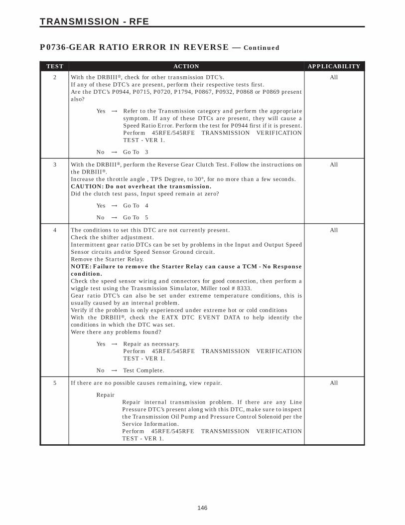
TEST ACTION APPLICABILITY
2 With the DRBIIIt, check for other transmission DTC’s.If any of these DTC’s are present, perform their respective tests first.Are the DTC’s P0944, P0715, P0720, P1794, P0867, P0932, P0868 or P0869 presentalso?
All
Yes → Refer to the Transmission category and perform the appropriatesymptom. If any of these DTCs are present, they will cause aSpeed Ratio Error. Perform the test for P0944 first if it is present.Perform 45RFE/545RFE TRANSMISSION VERIFICATIONTEST - VER 1.
No → Go To 3
3 With the DRBIIIt, perform the Reverse Gear Clutch Test. Follow the instructions onthe DRBIIIt.Increase the throttle angle , TPS Degree, to 30°, for no more than a few seconds.CAUTION: Do not overheat the transmission.Did the clutch test pass, Input speed remain at zero?
All
Yes → Go To 4
No → Go To 5
4 The conditions to set this DTC are not currently present.Check the shifter adjustment.Intermittent gear ratio DTCs can be set by problems in the Input and Output SpeedSensor circuits and/or Speed Sensor Ground circuit.Remove the Starter Relay.NOTE: Failure to remove the Starter Relay can cause a TCM - No Responsecondition.Check the speed sensor wiring and connectors for good connection, then perform awiggle test using the Transmission Simulator, Miller tool # 8333.Gear ratio DTC’s can also be set under extreme temperature conditions, this isusually caused by an internal problem.Verify if the problem is only experienced under extreme hot or cold conditionsWith the DRBIIIt, check the EATX DTC EVENT DATA to help identify theconditions in which the DTC was set.Were there any problems found?
All
Yes → Repair as necessary.Perform 45RFE/545RFE TRANSMISSION VERIFICATIONTEST - VER 1.
No → Test Complete.
5 If there are no possible causes remaining, view repair. All
RepairRepair internal transmission problem. If there are any LinePressure DTC’s present along with this DTC, make sure to inspectthe Transmission Oil Pump and Pressure Control Solenoid per theService Information.Perform 45RFE/545RFE TRANSMISSION VERIFICATIONTEST - VER 1.
146
TRANSMISSION - RFE
P0736-GEAR RATIO ERROR IN REVERSE — Continued

Symptom:P0740-TORQUE CONVERTER CLUTCH CONTROL CIRCUIT
When Monitored and Set Condition:
P0740-TORQUE CONVERTER CLUTCH CONTROL CIRCUIT
When Monitored: During Electronically Modulated Converter Clutch (EMCC) Operation.
Set Condition: Transmission must be in EMCC, with input speed > than 1750 RPM.TCC-L/R Solenoid achieves the maximum duty cycle and can not pull engine speed within60 RPM of input speed. Also when the transmission is in FEMCC and the engine slips TCC> than 100 RPM for 10 seconds. This DTC can take up to five minutes of problemidentification before illuminating the MIL.
POSSIBLE CAUSES
RELATED DTC P0750 PRESENT
INTERNAL TRANSMISSION
TRANSMISSION SOLENOID/TRS ASSEMBLY
INTERMITTENT WIRING AND CONNECTORS
TEST ACTION APPLICABILITY
1 NOTE: Low fluid level can be the cause of many transmission problems. Ifthe fluid level is low locate and repair the leak then check and adjust thefluid level per the Service Information.NOTE: Always perform diagnostics with a fully charged battery to avoidfalse symptoms.With the DRBIIIt, read the engine DTC’s. Check and repair all engine DTC’s priorto performing transmission symptom diagnostics.With the DRBIIIt, read Transmission DTC’s. Record all DTC’s and 1 Trip Failures.NOTE: Diagnose 1 Trip Failures as a fully matured DTC.Using the wiring diagram/schematic as a guide, inspect the wiring and connectors.Repair as necessary.Perform the Shift Lever Position Test. If the test does not pass, refer to Symptom testfor P0706 Check Shifter Signal.For Gear Ratio DTC’s, check and record all CVI’s.Most DTC’s set on start up but some must be set by driving the vehicle such that alldiagnostic monitors have run.NOTE: Verify the flash level of the transmission controller. Some problemsare corrected by software upgrades to the transmission controller.NOTE: Check for applicable TSB’s related to the problem.Perform this procedure prior to Symptom diagnosis.
All
ContinueGo To 2
147
TRANSMISSION - RFE
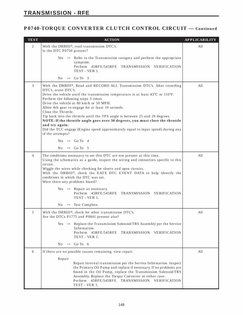
TEST ACTION APPLICABILITY
2 With the DRBIIIt, read transmission DTC’s.Is the DTC P0750 present?
All
Yes → Refer to the Transmission category and perform the appropriatesymptom.Perform 45RFE/545RFE TRANSMISSION VERIFICATIONTEST - VER 1.
No → Go To 3
3 With the DRBIIIt, Read and RECORD ALL Transmission DTC’s. After recordingDTC’s, erase DTC’s.Drive the vehicle until the transmission temperature is at least 43°C or 110°F.Perform the following steps 3 times.Drive the vehicle at 80 km/h or 50 MPH.Allow 4th gear to engage for at least 10 seconds.Close the Throttle.Tip back into the throttle until the TPS angle is between 25 and 29 degrees.NOTE: If the throttle angle goes over 30 degrees, you must close the throttleand try again.Did the TCC engage (Engine speed approximately equal to input speed) during anyof the attempts?
All
Yes → Go To 4
No → Go To 5
4 The conditions necessary to set this DTC are not present at this time.Using the schematics as a guide, inspect the wiring and connectors specific to thiscircuit.Wiggle the wires while checking for shorts and open circuits.With the DRBIIIt, check the EATX DTC EVENT DATA to help identify theconditions in which the DTC was set.Were there any problems found?
All
Yes → Repair as necessary.Perform 45RFE/545RFE TRANSMISSION VERIFICATIONTEST - VER 1.
No → Test Complete.
5 With the DRBIIIt, check for other transmission DTC’s.Are the DTCs P1775 and P0841 present also?
All
Yes → Replace the Transmission Solenoid/TRS Assembly per the ServiceInformation.Perform 45RFE/545RFE TRANSMISSION VERIFICATIONTEST - VER 1.
No → Go To 6
6 If there are no possible causes remaining, view repair. All
RepairRepair internal transmission per the Service Information. Inspectthe Primary Oil Pump and replace if necessary. If no problems arefound in the Oil Pump, replace the Transmission Solenoid/TRSAssembly. Replace the Torque Converter in either case.Perform 45RFE/545RFE TRANSMISSION VERIFICATIONTEST - VER 1.
148
TRANSMISSION - RFE
P0740-TORQUE CONVERTER CLUTCH CONTROL CIRCUIT — Continued

Symptom:P0750-LR SOLENOID CIRCUIT
When Monitored and Set Condition:
P0750-LR SOLENOID CIRCUIT
When Monitored: Initially at power-up, then every 10 seconds thereafter. It will also betested immediately after a gear ratio or pressure switch error is detected.
Set Condition: After three consecutive solenoid continuity tests failures. After one failureif a test is run in response to a gear ratio or pressure switch error.
POSSIBLE CAUSES
RELATED RELAY DTC’S PRESENT
TRANSMISSION CONTROL RELAY OUTPUT CIRCUIT OPEN
LR SOLENOID CONTROL CIRCUIT OPEN
LR SOLENOID CONTROL CIRCUIT SHORT TO GROUND
LR SOLENOID CONTROL CIRCUIT SHORT TO VOLTAGE
TRANSMISSION SOLENOID/TRS ASSEMBLY
TRANSMISSION CONTROL MODULE
INTERMITTENT WIRING AND CONNECTORS
TEST ACTION APPLICABILITY
1 NOTE: Low fluid level can be the cause of many transmission problems. Ifthe fluid level is low locate and repair the leak then check and adjust thefluid level per the Service Information.NOTE: Always perform diagnostics with a fully charged battery to avoidfalse symptoms.With the DRBIIIt, read the engine DTC’s. Check and repair all engine DTC’s priorto performing transmission symptom diagnostics.With the DRBIIIt, read Transmission DTC’s. Record all DTC’s and 1 Trip Failures.NOTE: Diagnose 1 Trip Failures as a fully matured DTC.Using the wiring diagram/schematic as a guide, inspect the wiring and connectors.Repair as necessary.Perform the Shift Lever Position Test. If the test does not pass, refer to Symptom testfor P0706 Check Shifter Signal.For Gear Ratio DTC’s, check and record all CVI’s.Most DTC’s set on start up but some must be set by driving the vehicle such that alldiagnostic monitors have run.NOTE: Verify the flash level of the transmission controller. Some problemsare corrected by software upgrades to the transmission controller.NOTE: Check for applicable TSB’s related to the problem.Perform this procedure prior to Symptom diagnosis.
All
ContinueGo To 2
149
TRANSMISSION - RFE

TEST ACTION APPLICABILITY
2 With the DRBIIIt, check for other transmission DTC’s.Are there any Transmission Control Relay related DTC’s P0890, P0891, or P0888present?
All
Yes → Refer to the Transmission category and perform the appropriatesymptom.Perform 45RFE/545RFE TRANSMISSION VERIFICATIONTEST - VER 1.
No → Go To 3
3 With the DRBIIIt, check the STARTS SINCE SET counter for P0750.NOTE: This counter only applies to the last DTC set.Is the STARTS SINCE SET counter for P0750 set at 0?
All
Yes → Go To 4
No → Go To 11
4 Turn the ignition off to the lock position.Remove the Starter Relay.NOTE: Failure to remove the Starter Relay can cause a Transmission - NoResponse condition.Install the Transmission Simulator, Miller tool #8333.Note: Check connectors - Clean/repair as necessary.Ignition on, engine not running.Monitor the LR Solenoid LED on the Transmission Simulator.With the DRBIIIt, actuate the LR Solenoid.Did the LR Solenoid LED on the Transmission Simulator blink on and off?
All
Yes → Go To 5
No → Go To 6
5 If there are no possible causes remaining, view repair. All
RepairReplace the Transmission Solenoid/TRS Assembly per the ServiceInformation.Perform 45RFE/545RFE TRANSMISSION VERIFICATIONTEST - VER 1.
6 Turn the ignition off to the lock position.Disconnect the TCM harness connectorDisconnect the Transmission Solenoid /TRS Assembly harness connectorNote: Check connectors - Clean/repair as necessary.Measure the resistance of the LR Solenoid Control circuit from the TCM harnessconnector to the Transmission Solenoid/TRS Assembly harness connector.Is the resistance above 5.0 ohms?
All
Yes → Repair the LR Solenoid Control circuit for an open.Perform 45RFE/545RFE TRANSMISSION VERIFICATIONTEST - VER 1.
No → Go To 7
150
TRANSMISSION - RFE
P0750-LR SOLENOID CIRCUIT — Continued
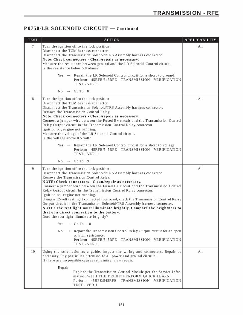
TEST ACTION APPLICABILITY
7 Turn the ignition off to the lock position.Disconnect the TCM harness connector.Disconnect the Transmission Solenoid/TRS Assembly harness connector.Note: Check connectors - Clean/repair as necessary.Measure the resistance between ground and the LR Solenoid Control circuit.Is the resistance below 5.0 ohms?
All
Yes → Repair the LR Solenoid Control circuit for a short to ground.Perform 45RFE/545RFE TRANSMISSION VERIFICATIONTEST - VER 1.
No → Go To 8
8 Turn the ignition off to the lock position.Disconnect the TCM harness connector.Disconnect the Transmission Solenoid/TRS Assembly harness connector.Remove the Transmission Control Relay.Note: Check connectors - Clean/repair as necessary.Connect a jumper wire between the Fused B+ circuit and the Transmission ControlRelay Output circuit in the Transmission Control Relay connector.Ignition on, engine not running.Measure the voltage of the LR Solenoid Control circuit.Is the voltage above 0.5 volt?
All
Yes → Repair the LR Solenoid Control circuit for a short to voltage.Perform 45RFE/545RFE TRANSMISSION VERIFICATIONTEST - VER 1.
No → Go To 9
9 Turn the ignition off to the lock position.Disconnect the Transmission Solenoid/TRS Assembly harness connector.Remove the Transmission Control Relay.NOTE: Check connectors - Clean/repair as necessary.Connect a jumper wire between the Fused B+ circuit and the Transmission ControlRelay Output circuit in the Transmission Control Relay connector.Ignition on, engine not running.Using a 12-volt test light connected to ground, check the Transmission Control RelayOutput circuit in the Transmission Solenoid/TRS Assembly harness connector.NOTE: The test light must illuminate brightly. Compare the brightness tothat of a direct connection to the battery.Does the test light illuminate brightly?
All
Yes → Go To 10
No → Repair the Transmission Control Relay Output circuit for an openor high resistance.Perform 45RFE/545RFE TRANSMISSION VERIFICATIONTEST - VER 1.
10 Using the schematics as a guide, inspect the wiring and connectors. Repair asnecessary. Pay particular attention to all power and ground circuits.If there are no possible causes remaining, view repair.
All
RepairReplace the Transmission Control Module per the Service Infor-mation. WITH THE DRBIIIt PERFORM QUICK LEARN.Perform 45RFE/545RFE TRANSMISSION VERIFICATIONTEST - VER 1.
151
TRANSMISSION - RFE
P0750-LR SOLENOID CIRCUIT — Continued
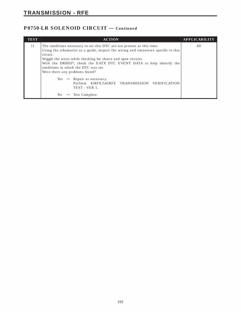
TEST ACTION APPLICABILITY
11 The conditions necessary to set this DTC are not present at this time.Using the schematics as a guide, inspect the wiring and connectors specific to thiscircuit.Wiggle the wires while checking for shorts and open circuits.With the DRBIIIt, check the EATX DTC EVENT DATA to help identify theconditions in which the DTC was set.Were there any problems found?
All
Yes → Repair as necessary.Perform 45RFE/545RFE TRANSMISSION VERIFICATIONTEST - VER 1.
No → Test Complete.
152
TRANSMISSION - RFE
P0750-LR SOLENOID CIRCUIT — Continued

Symptom:P0755-2C SOLENOID CIRCUIT
When Monitored and Set Condition:
P0755-2C SOLENOID CIRCUIT
When Monitored: Initially at power-up, then every 10 seconds thereafter. It will also betested immediately after a gear ratio or pressure switch error is detected.
Set Condition: After three consecutive solenoid continuity tests failures. After one failureif a test is run in response to a gear ratio or pressure switch error.
POSSIBLE CAUSES
RELATED RELAY DTC’S PRESENT
TRANSMISSION CONTROL RELAY OUTPUT CIRCUIT OPEN
2C SOLENOID CONTROL CIRCUIT OPEN
2C SOLENOID CONTROL CIRCUIT SHORT TO GROUND
2C SOLENOID CONTROL CIRCUIT SHORT TO VOLTAGE
TRANSMISSION SOLENOID/TRS ASSEMBLY
TRANSMISSION CONTROL MODULE
INTERMITTENT WIRING AND CONNECTORS
TEST ACTION APPLICABILITY
1 NOTE: Low fluid level can be the cause of many transmission problems. Ifthe fluid level is low locate and repair the leak then check and adjust thefluid level per the Service Information.NOTE: Always perform diagnostics with a fully charged battery to avoidfalse symptoms.With the DRBIIIt, read the engine DTC’s. Check and repair all engine DTC’s priorto performing transmission symptom diagnostics.With the DRBIIIt, read Transmission DTC’s. Record all DTC’s and 1 Trip Failures.NOTE: Diagnose 1 Trip Failures as a fully matured DTC.Using the wiring diagram/schematic as a guide, inspect the wiring and connectors.Repair as necessary.Perform the Shift Lever Position Test. If the test does not pass, refer to Symptom testfor P0706 Check Shifter Signal.For Gear Ratio DTC’s, check and record all CVI’s.Most DTC’s set on start up but some must be set by driving the vehicle such that alldiagnostic monitors have run.NOTE: Verify the flash level of the transmission controller. Some problemsare corrected by software upgrades to the transmission controller.NOTE: Check for applicable TSB’s related to the problem.Perform this procedure prior to Symptom diagnosis.
All
ContinueGo To 2
153
TRANSMISSION - RFE
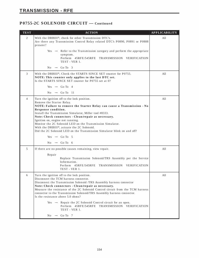
TEST ACTION APPLICABILITY
2 With the DRBIIIt, check for other Transmission DTC’s.Are there any Transmission Control Relay related DTC’s P0890, P0891 or P0888present?
All
Yes → Refer to the Transmission category and perform the appropriatesymptom.Perform 45RFE/545RFE TRANSMISSION VERIFICATIONTEST - VER 1.
No → Go To 3
3 With the DRBIIIt, Check the STARTS SINCE SET counter for P0755.NOTE: This counter only applies to the last DTC set.Is the STARTS SINCE SET counter for P0755 set at 0?
All
Yes → Go To 4
No → Go To 11
4 Turn the ignition off to the lock position.Remove the Starter Relay.NOTE: Failure to remove the Starter Relay can cause a Transmission - NoResponse condition.Install the Transmission Simulator, Miller tool #8333.Note: Check connectors - Clean/repair as necessary.Ignition on, engine not running.Monitor the 2C Solenoid LED on the Transmission Simulator.With the DRBIIIt, actuate the 2C Solenoid.Did the 2C Solenoid LED on the Transmission Simulator blink on and off?
All
Yes → Go To 5
No → Go To 6
5 If there are no possible causes remaining, view repair. All
RepairReplace Transmission Solenoid/TRS Assembly per the ServiceInformation.Perform 45RFE/545RFE TRANSMISSION VERIFICATIONTEST - VER 1.
6 Turn the ignition off to the lock position.Disconnect the TCM harness connector.Disconnect the Transmission Solenoid /TRS Assembly harness connectorNote: Check connectors - Clean/repair as necessary.Measure the resistance of the 2C Solenoid Control circuit from the TCM harnessconnector to the Transmission Solenoid/TRS Assembly harness connector.Is the resistance above 5.0 ohms?
All
Yes → Repair the 2C Solenoid Control circuit for an open.Perform 45RFE/545RFE TRANSMISSION VERIFICATIONTEST - VER 1.
No → Go To 7
154
TRANSMISSION - RFE
P0755-2C SOLENOID CIRCUIT — Continued

TEST ACTION APPLICABILITY
7 Turn the ignition off to the lock position.Disconnect the TCM harness connector.Disconnect the Transmission Solenoid/TRS Assembly harness connector.Note: Check connectors - Clean/repair as necessary.Measure the resistance between ground and the 2C Solenoid Control circuit.Is the resistance below 5.0 ohms?
All
Yes → Repair the 2C Solenoid Control circuit for a short to ground.Perform 45RFE/545RFE TRANSMISSION VERIFICATIONTEST - VER 1.
No → Go To 8
8 Turn the ignition off to the lock position.Disconnect the TCM harness connector.Disconnect the Transmission Solenoid/TRS Assembly harness connector.Remove the Transmission Control Relay.Note: Check connectors - Clean/repair as necessary.Connect a jumper wire between the Fused B+ circuit and the Transmission ControlRelay Output circuit in the Transmission Control Relay connector.Ignition on, engine not running.Measure the voltage of the 2C Solenoid Control circuit.Is the voltage above 0.5 volt?
All
Yes → Repair the 2C Solenoid Control circuit for a short to voltage.Perform 45RFE/545RFE TRANSMISSION VERIFICATIONTEST - VER 1.
No → Go To 9
9 Turn the ignition off to the lock position.Disconnect the Transmission Solenoid/TRS Assembly harness connector.Remove the Transmission Control Relay.NOTE: Check connectors - Clean/repair as necessary.Connect a jumper wire between the Fused B+ circuit and the Transmission ControlRelay Output circuit in the Transmission Control Relay connector.Ignition on, engine not running.Using a 12-volt test light connected to ground, check the Transmission Control RelayOutput circuit in the Transmission Solenoid/TRS Assembly harness connector.NOTE: The test light must illuminate brightly. Compare the brightness tothat of a direct connection to the battery.Does the test light illuminate brightly?
All
Yes → Go To 10
No → Repair the Transmission Control Relay Output circuit for an openor high resistance.Perform 45RFE/545RFE TRANSMISSION VERIFICATIONTEST - VER 1.
10 Using the schematics as a guide, inspect the wiring and connectors. Repair asnecessary. Pay particular attention to all power and ground circuits.If there are no possible causes remaining, view repair.
All
RepairReplace the Transmission Control Module per the Service Infor-mation. WITH THE DRBIIIt PERFORM QUICK LEARN.Perform 45RFE/545RFE TRANSMISSION VERIFICATIONTEST - VER 1.
155
TRANSMISSION - RFE
P0755-2C SOLENOID CIRCUIT — Continued

TEST ACTION APPLICABILITY
11 The conditions necessary to set this DTC are not present at this time.Using the schematics as a guide, inspect the wiring and connectors specific to thiscircuit.Wiggle the wires while checking for shorts and open circuits.With the DRBIIIt, check the EATX DTC EVENT DATA to help identify theconditions in which the DTC was set.Were there any problems found?
All
Yes → Repair as necessaryPerform 45RFE/545RFE TRANSMISSION VERIFICATIONTEST - VER 1.
No → Test Complete.
156
TRANSMISSION - RFE
P0755-2C SOLENOID CIRCUIT — Continued

Symptom:P0760-OD SOLENOID CIRCUIT
When Monitored and Set Condition:
P0760-OD SOLENOID CIRCUIT
When Monitored: Initially at power-up, then every 10 seconds thereafter. It will also betested immediately after a gear ratio or pressure switch error is detected.
Set Condition: After three consecutive solenoid continuity tests failures. After one failureif a test is run in response to a gear ratio or pressure switch error.
POSSIBLE CAUSES
RELATED RELAY DTC’S PRESENT
TRANSMISSION CONTROL RELAY OUTPUT CIRCUIT OPEN
OD SOLENOID CONTROL CIRCUIT OPEN
OD SOLENOID CONTROL CIRCUIT SHORT TO GROUND
OD SOLENOID CONTROL CIRCUIT SHORT TO VOLTAGE
TRANSMISSION SOLENOID/TRS ASSEMBLY
TRANSMISSION CONTROL MODULE
INTERMITTENT WIRING AND CONNECTORS
TEST ACTION APPLICABILITY
1 NOTE: Low fluid level can be the cause of many transmission problems. Ifthe fluid level is low locate and repair the leak then check and adjust thefluid level per the Service Information.NOTE: Always perform diagnostics with a fully charged battery to avoidfalse symptoms.With the DRBIIIt, read the engine DTC’s. Check and repair all engine DTC’s priorto performing transmission symptom diagnostics.With the DRBIIIt, read Transmission DTC’s. Record all DTC’s and 1 Trip Failures.NOTE: Diagnose 1 Trip Failures as a fully matured DTC.Using the wiring diagram/schematic as a guide, inspect the wiring and connectors.Repair as necessary.Perform the Shift Lever Position Test. If the test does not pass, refer to Symptom testfor P0706 Check Shifter Signal.For Gear Ratio DTC’s, check and record all CVI’s.Most DTC’s set on start up but some must be set by driving the vehicle such that alldiagnostic monitors have run.NOTE: Verify the flash level of the transmission controller. Some problemsare corrected by software upgrades to the transmission controller.NOTE: Check for applicable TSB’s related to the problem.Perform this procedure prior to Symptom diagnosis.
All
ContinueGo To 2
157
TRANSMISSION - RFE
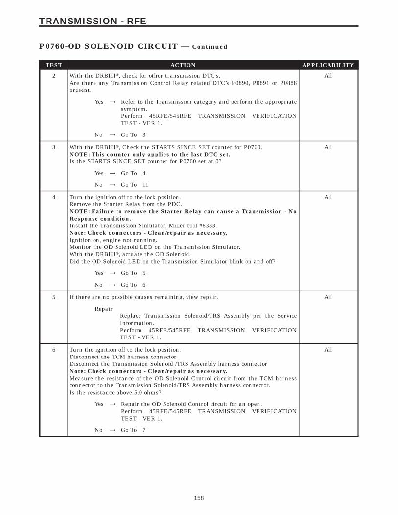
TEST ACTION APPLICABILITY
2 With the DRBIIIt, check for other transmission DTC’s.Are there any Transmission Control Relay related DTC’s P0890, P0891 or P0888present.
All
Yes → Refer to the Transmission category and perform the appropriatesymptom.Perform 45RFE/545RFE TRANSMISSION VERIFICATIONTEST - VER 1.
No → Go To 3
3 With the DRBIIIt, Check the STARTS SINCE SET counter for P0760.NOTE: This counter only applies to the last DTC set.Is the STARTS SINCE SET counter for P0760 set at 0?
All
Yes → Go To 4
No → Go To 11
4 Turn the ignition off to the lock position.Remove the Starter Relay from the PDC.NOTE: Failure to remove the Starter Relay can cause a Transmission - NoResponse condition.Install the Transmission Simulator, Miller tool #8333.Note: Check connectors - Clean/repair as necessary.Ignition on, engine not running.Monitor the OD Solenoid LED on the Transmission Simulator.With the DRBIIIt, actuate the OD Solenoid.Did the OD Solenoid LED on the Transmission Simulator blink on and off?
All
Yes → Go To 5
No → Go To 6
5 If there are no possible causes remaining, view repair. All
RepairReplace Transmission Solenoid/TRS Assembly per the ServiceInformation.Perform 45RFE/545RFE TRANSMISSION VERIFICATIONTEST - VER 1.
6 Turn the ignition off to the lock position.Disconnect the TCM harness connector.Disconnect the Transmission Solenoid /TRS Assembly harness connectorNote: Check connectors - Clean/repair as necessary.Measure the resistance of the OD Solenoid Control circuit from the TCM harnessconnector to the Transmission Solenoid/TRS Assembly harness connector.Is the resistance above 5.0 ohms?
All
Yes → Repair the OD Solenoid Control circuit for an open.Perform 45RFE/545RFE TRANSMISSION VERIFICATIONTEST - VER 1.
No → Go To 7
158
TRANSMISSION - RFE
P0760-OD SOLENOID CIRCUIT — Continued
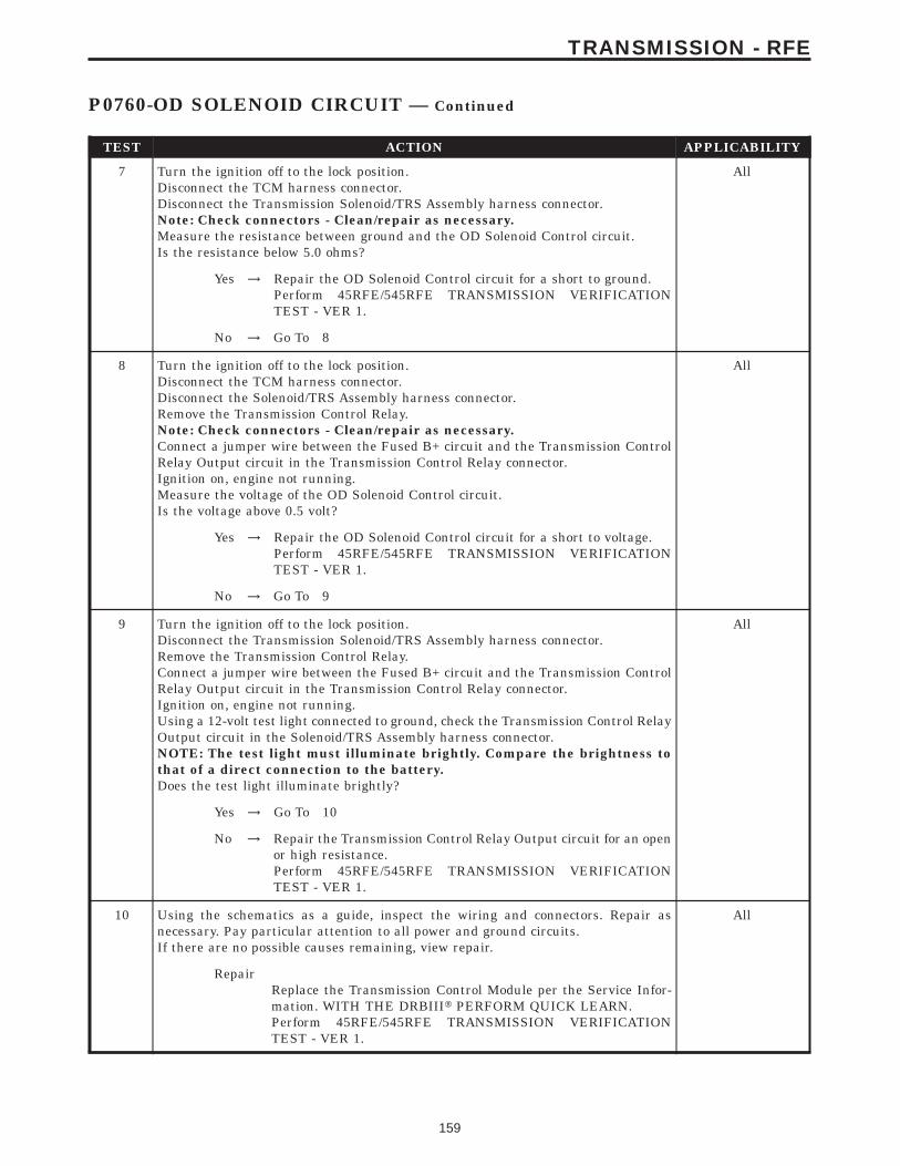
TEST ACTION APPLICABILITY
7 Turn the ignition off to the lock position.Disconnect the TCM harness connector.Disconnect the Transmission Solenoid/TRS Assembly harness connector.Note: Check connectors - Clean/repair as necessary.Measure the resistance between ground and the OD Solenoid Control circuit.Is the resistance below 5.0 ohms?
All
Yes → Repair the OD Solenoid Control circuit for a short to ground.Perform 45RFE/545RFE TRANSMISSION VERIFICATIONTEST - VER 1.
No → Go To 8
8 Turn the ignition off to the lock position.Disconnect the TCM harness connector.Disconnect the Solenoid/TRS Assembly harness connector.Remove the Transmission Control Relay.Note: Check connectors - Clean/repair as necessary.Connect a jumper wire between the Fused B+ circuit and the Transmission ControlRelay Output circuit in the Transmission Control Relay connector.Ignition on, engine not running.Measure the voltage of the OD Solenoid Control circuit.Is the voltage above 0.5 volt?
All
Yes → Repair the OD Solenoid Control circuit for a short to voltage.Perform 45RFE/545RFE TRANSMISSION VERIFICATIONTEST - VER 1.
No → Go To 9
9 Turn the ignition off to the lock position.Disconnect the Transmission Solenoid/TRS Assembly harness connector.Remove the Transmission Control Relay.Connect a jumper wire between the Fused B+ circuit and the Transmission ControlRelay Output circuit in the Transmission Control Relay connector.Ignition on, engine not running.Using a 12-volt test light connected to ground, check the Transmission Control RelayOutput circuit in the Solenoid/TRS Assembly harness connector.NOTE: The test light must illuminate brightly. Compare the brightness tothat of a direct connection to the battery.Does the test light illuminate brightly?
All
Yes → Go To 10
No → Repair the Transmission Control Relay Output circuit for an openor high resistance.Perform 45RFE/545RFE TRANSMISSION VERIFICATIONTEST - VER 1.
10 Using the schematics as a guide, inspect the wiring and connectors. Repair asnecessary. Pay particular attention to all power and ground circuits.If there are no possible causes remaining, view repair.
All
RepairReplace the Transmission Control Module per the Service Infor-mation. WITH THE DRBIIIt PERFORM QUICK LEARN.Perform 45RFE/545RFE TRANSMISSION VERIFICATIONTEST - VER 1.
159
TRANSMISSION - RFE
P0760-OD SOLENOID CIRCUIT — Continued

TEST ACTION APPLICABILITY
11 The conditions necessary to set this DTC are not present at this time.Using the schematics as a guide, inspect the wiring and connectors specific to thiscircuit.Wiggle the wires while checking for shorts and open circuits.With the DRBIIIt, check the EATX DTC EVENT DATA to help identify theconditions in which the DTC was set.Were there any problems found?
All
Yes → Repair as necessary.Perform 45RFE/545RFE TRANSMISSION VERIFICATIONTEST - VER 1.
No → Test Complete.
160
TRANSMISSION - RFE
P0760-OD SOLENOID CIRCUIT — Continued

Symptom:P0765-UD SOLENOID CIRCUIT
When Monitored and Set Condition:
P0765-UD SOLENOID CIRCUIT
When Monitored: Initially at power-up, then every 10 seconds thereafter. It will also betested immediately after a gear ratio or pressure switch error is detected.
Set Condition: After three consecutive solenoid continuity tests failures. After one failureif a test is run in response to a gear ratio or pressure switch error.
POSSIBLE CAUSES
RELATED RELAY DTC’S PRESENT
TRANSMISSION CONTROL RELAY OUTPUT CIRCUIT OPEN
UD SOLENOID CONTROL CIRCUIT OPEN
UD SOLENOID CONTROL CIRCUIT SHORT TO GROUND
UD SOLENOID CONTROL CIRCUIT SHORT TO VOLTAGE
TRANSMISSION SOLENOID/TRS ASSEMBLY
TRANSMISSION CONTROL MODULE
INTERMITTENT WIRING AND CONNECTORS
TEST ACTION APPLICABILITY
1 NOTE: Low fluid level can be the cause of many transmission problems. Ifthe fluid level is low locate and repair the leak then check and adjust thefluid level per the Service Information.NOTE: Always perform diagnostics with a fully charged battery to avoidfalse symptoms.With the DRBIIIt, read the engine DTC’s. Check and repair all engine DTC’s priorto performing transmission symptom diagnostics.With the DRBIIIt, read Transmission DTC’s. Record all DTC’s and 1 Trip Failures.NOTE: Diagnose 1 Trip Failures as a fully matured DTC.Using the wiring diagram/schematic as a guide, inspect the wiring and connectors.Repair as necessary.Perform the Shift Lever Position Test. If the test does not pass, refer to Symptom testfor P0706 Check Shifter Signal.For Gear Ratio DTC’s, check and record all CVI’s.Most DTC’s set on start up but some must be set by driving the vehicle such that alldiagnostic monitors have run.NOTE: Verify the flash level of the transmission controller. Some problemsare corrected by software upgrades to the transmission controller.NOTE: Check for applicable TSB’s related to the problem.Perform this procedure prior to Symptom diagnosis.
All
ContinueGo To 2
161
TRANSMISSION - RFE
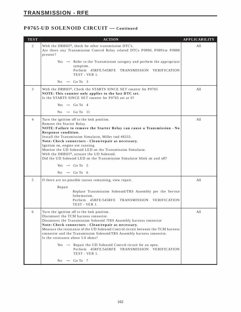
TEST ACTION APPLICABILITY
2 With the DRBIIIt, check for other transmission DTC’s.Are there any Transmission Control Relay related DTCs P0890, P0891or P0888present?
All
Yes → Refer to the Transmission category and perform the appropriatesymptom.Perform 45RFE/545RFE TRANSMISSION VERIFICATIONTEST - VER 1.
No → Go To 3
3 With the DRBIIIt, Check the STARTS SINCE SET counter for P0765NOTE: This counter only applies to the last DTC set.Is the STARTS SINCE SET counter for P0765 set at 0?
All
Yes → Go To 4
No → Go To 11
4 Turn the ignition off to the lock position.Remove the Starter Relay.NOTE: Failure to remove the Starter Relay can cause a Transmission - NoResponse condition.Install the Transmission Simulator, Miller tool #8333.Note: Check connectors - Clean/repair as necessary.Ignition on, engine not running.Monitor the UD Solenoid LED on the Transmission Simulator.With the DRBIIIt, actuate the UD Solenoid.Did the UD Solenoid LED on the Transmission Simulator blink on and off?
All
Yes → Go To 5
No → Go To 6
5 If there are no possible causes remaining, view repair. All
RepairReplace Transmission Solenoid/TRS Assembly per the ServiceInformation.Perform 45RFE/545RFE TRANSMISSION VERIFICATIONTEST - VER 1.
6 Turn the ignition off to the lock position.Disconnect the TCM harness connector.Disconnect the Transmission Solenoid /TRS Assembly harness connectorNote: Check connectors - Clean/repair as necessary.Measure the resistance of the UD Solenoid Control circuit between the TCM harnessconnector and the Transmission Solenoid/TRS Assembly harness connector.Is the resistance above 5.0 ohms?
All
Yes → Repair the UD Solenoid Control circuit for an open.Perform 45RFE/545RFE TRANSMISSION VERIFICATIONTEST - VER 1.
No → Go To 7
162
TRANSMISSION - RFE
P0765-UD SOLENOID CIRCUIT — Continued

TEST ACTION APPLICABILITY
7 Turn the ignition off to the lock position.Disconnect the TCM harness connector.Disconnect the Transmission Solenoid/TRS harness connector.Note: Check connectors - Clean/repair as necessary.Measure the resistance between ground and the UD Solenoid Control circuit.Is the resistance below 5.0 ohms?
All
Yes → Repair the UD Solenoid Control circuit for a short to ground.Perform 45RFE/545RFE TRANSMISSION VERIFICATIONTEST - VER 1.
No → Go To 8
8 Turn the ignition off to the lock position.Disconnect the TCM harness connector.Disconnect the Transmission Solenoid/TRS Assembly harness connector.Remove the Transmission Control Relay.Note: Check connectors - Clean/repair as necessary.Connect a jumper wire between the Fused B+ circuit and the Transmission ControlRelay Output circuit in the Transmission Control Relay connector.Ignition on, engine not running.Measure the voltage of the UD Solenoid Control circuit.Is the voltage above 0.5 volt?
All
Yes → Repair the UD Solenoid Control circuit for a short to voltage.Perform 45RFE/545RFE TRANSMISSION VERIFICATIONTEST - VER 1.
No → Go To 9
9 Turn the ignition off to the lock position.Disconnect the Transmission Solenoid/TRS Assembly harness connector.Remove the Transmission Control Relay.NOTE: Check connectors - Clean/repair as necessary.Connect a jumper wire between the Fused B+ circuit and the Transmission ControlRelay Output circuit in the Transmission Control Relay connector.Ignition on, engine not running.Using a 12-volt test light connected to ground, check the Transmission Control RelayOutput circuit in the Transmission Solenoid/TRS Assembly harness connector.NOTE: The test light must illuminate brightly. Compare the brightness tothat of a direct connection to the battery.Does the test light illuminate brightly?
All
Yes → Go To 10
No → Repair the Transmission Control Relay Output circuit for an openor high resistance.Perform 45RFE/545RFE TRANSMISSION VERIFICATIONTEST - VER 1.
10 Using the schematics as a guide, inspect the wiring and connectors. Repair asnecessary. Pay particular attention to all power and ground circuits.If there are no possible causes remaining, view repair.
All
RepairReplace the Transmission Control Module per the Service Infor-mation. WITH THE DRBIIIt PERFORM QUICK LEARN.Perform 45RFE/545RFE TRANSMISSION VERIFICATIONTEST - VER 1.
163
TRANSMISSION - RFE
P0765-UD SOLENOID CIRCUIT — Continued

TEST ACTION APPLICABILITY
11 The conditions necessary to set this DTC are not present at this time.Using the schematics as a guide, inspect the wiring and connectors specific to thiscircuit.Wiggle the wires while checking for shorts and open circuits.With the DRBIIIt, check the EATX DTC EVENT DATA to help identify theconditions in which the DTC was set.Were there any problems found?
All
Yes → Repair as necessary.Perform 45RFE/545RFE TRANSMISSION VERIFICATIONTEST - VER 1.
No → Test Complete.
164
TRANSMISSION - RFE
P0765-UD SOLENOID CIRCUIT — Continued
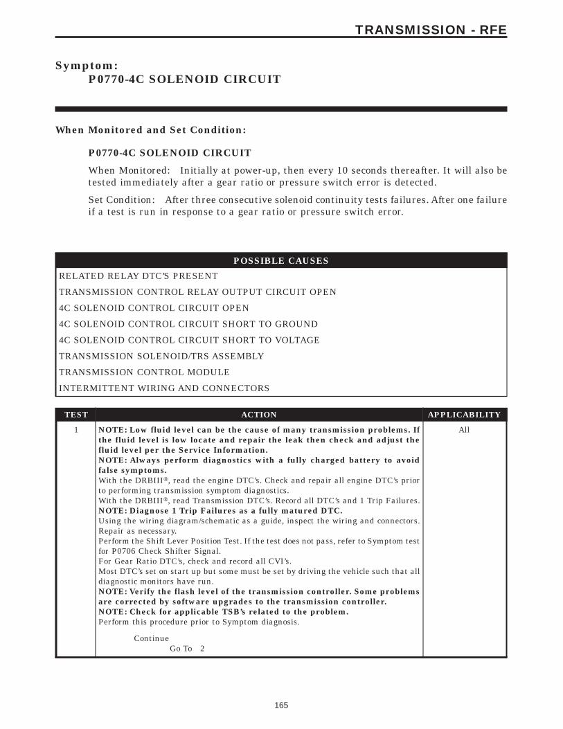
Symptom:P0770-4C SOLENOID CIRCUIT
When Monitored and Set Condition:
P0770-4C SOLENOID CIRCUIT
When Monitored: Initially at power-up, then every 10 seconds thereafter. It will also betested immediately after a gear ratio or pressure switch error is detected.
Set Condition: After three consecutive solenoid continuity tests failures. After one failureif a test is run in response to a gear ratio or pressure switch error.
POSSIBLE CAUSES
RELATED RELAY DTC’S PRESENT
TRANSMISSION CONTROL RELAY OUTPUT CIRCUIT OPEN
4C SOLENOID CONTROL CIRCUIT OPEN
4C SOLENOID CONTROL CIRCUIT SHORT TO GROUND
4C SOLENOID CONTROL CIRCUIT SHORT TO VOLTAGE
TRANSMISSION SOLENOID/TRS ASSEMBLY
TRANSMISSION CONTROL MODULE
INTERMITTENT WIRING AND CONNECTORS
TEST ACTION APPLICABILITY
1 NOTE: Low fluid level can be the cause of many transmission problems. Ifthe fluid level is low locate and repair the leak then check and adjust thefluid level per the Service Information.NOTE: Always perform diagnostics with a fully charged battery to avoidfalse symptoms.With the DRBIIIt, read the engine DTC’s. Check and repair all engine DTC’s priorto performing transmission symptom diagnostics.With the DRBIIIt, read Transmission DTC’s. Record all DTC’s and 1 Trip Failures.NOTE: Diagnose 1 Trip Failures as a fully matured DTC.Using the wiring diagram/schematic as a guide, inspect the wiring and connectors.Repair as necessary.Perform the Shift Lever Position Test. If the test does not pass, refer to Symptom testfor P0706 Check Shifter Signal.For Gear Ratio DTC’s, check and record all CVI’s.Most DTC’s set on start up but some must be set by driving the vehicle such that alldiagnostic monitors have run.NOTE: Verify the flash level of the transmission controller. Some problemsare corrected by software upgrades to the transmission controller.NOTE: Check for applicable TSB’s related to the problem.Perform this procedure prior to Symptom diagnosis.
All
ContinueGo To 2
165
TRANSMISSION - RFE
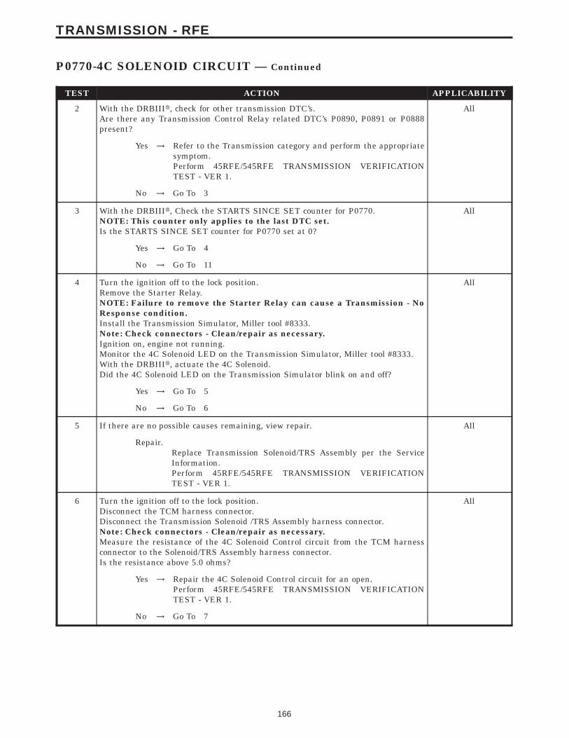
TEST ACTION APPLICABILITY
2 With the DRBIIIt, check for other transmission DTC’s.Are there any Transmission Control Relay related DTC’s P0890, P0891 or P0888present?
All
Yes → Refer to the Transmission category and perform the appropriatesymptom.Perform 45RFE/545RFE TRANSMISSION VERIFICATIONTEST - VER 1.
No → Go To 3
3 With the DRBIIIt, Check the STARTS SINCE SET counter for P0770.NOTE: This counter only applies to the last DTC set.Is the STARTS SINCE SET counter for P0770 set at 0?
All
Yes → Go To 4
No → Go To 11
4 Turn the ignition off to the lock position.Remove the Starter Relay.NOTE: Failure to remove the Starter Relay can cause a Transmission - NoResponse condition.Install the Transmission Simulator, Miller tool #8333.Note: Check connectors - Clean/repair as necessary.Ignition on, engine not running.Monitor the 4C Solenoid LED on the Transmission Simulator, Miller tool #8333.With the DRBIIIt, actuate the 4C Solenoid.Did the 4C Solenoid LED on the Transmission Simulator blink on and off?
All
Yes → Go To 5
No → Go To 6
5 If there are no possible causes remaining, view repair. All
Repair.Replace Transmission Solenoid/TRS Assembly per the ServiceInformation.Perform 45RFE/545RFE TRANSMISSION VERIFICATIONTEST - VER 1.
6 Turn the ignition off to the lock position.Disconnect the TCM harness connector.Disconnect the Transmission Solenoid /TRS Assembly harness connector.Note: Check connectors - Clean/repair as necessary.Measure the resistance of the 4C Solenoid Control circuit from the TCM harnessconnector to the Solenoid/TRS Assembly harness connector.Is the resistance above 5.0 ohms?
All
Yes → Repair the 4C Solenoid Control circuit for an open.Perform 45RFE/545RFE TRANSMISSION VERIFICATIONTEST - VER 1.
No → Go To 7
166
TRANSMISSION - RFE
P0770-4C SOLENOID CIRCUIT — Continued

TEST ACTION APPLICABILITY
7 Turn the ignition off to the lock position.Disconnect the TCM harness connector.Disconnect the Transmission Solenoid/TRS Assembly harness connector.Note: Check connectors - Clean/repair as necessary.Measure the resistance between ground and the 4C Solenoid Control circuit.Is the resistance below 5.0 ohms?
All
Yes → Repair the 4C Solenoid Control circuit for a short to ground.Perform 45RFE/545RFE TRANSMISSION VERIFICATIONTEST - VER 1.
No → Go To 8
8 Turn the ignition off to the lock position.Disconnect the Transmission Control Module harness connector.Disconnect the Transmission Solenoid/TRS Assembly harness connector.Remove the Transmission Control Relay.Note: Check connectors - Clean/repair as necessary.Connect a jumper wire between the Fused B+ circuit and the Transmission ControlRelay Output circuit in the Transmission Control Relay connector.Ignition on, engine not running.Measure the voltage of the 4C Solenoid Control circuit.Is the voltage above 0.5 volt?
All
Yes → Repair the 4C Solenoid Control circuit for a short to voltage.Perform 45RFE/545RFE TRANSMISSION VERIFICATIONTEST - VER 1.
No → Go To 9
9 Turn the ignition off to the lock position.Disconnect the Transmission Solenoid/TRS Assembly harness connector.Remove the Transmission Control Relay.Connect a jumper wire between the Fused B+ circuit and the Transmission ControlRelay Output circuit in the Transmission Control Relay connector.Ignition on, engine not running.Using a 12-volt test light connected to ground, check the Transmission Control RelayOutput circuit in the Solenoid/TRS Assembly harness connector.NOTE: The test light must illuminate brightly. Compare the brightness tothat of a direct connection to the battery.Does the test light illuminate brightly?
All
Yes → Go To 10
No → Repair the Transmission Control Relay Output circuit for an openor high resistance.Perform 45RFE/545RFE TRANSMISSION VERIFICATIONTEST - VER 1.
10 Using the schematics as a guide, inspect the wiring and connectors. Repair asnecessary. Pay particular attention to all power and ground circuits.If there are no possible causes remaining, view repair.
All
RepairReplace the Transmission Control Module per the Service Infor-mation. WITH THE DRBIIIt PERFORM QUICK LEARN.Perform 45RFE/545RFE TRANSMISSION VERIFICATIONTEST - VER 1.
167
TRANSMISSION - RFE
P0770-4C SOLENOID CIRCUIT — Continued

TEST ACTION APPLICABILITY
11 The conditions necessary to set this DTC are not present at this time.Using the schematics as a guide, inspect the wiring and connectors specific to thiscircuit.Wiggle the wires while checking for shorts and open circuits.With the DRBIIIt, check the EATX DTC EVENT DATA to help identify theconditions in which the DTC was set.Were there any problems found?
All
Yes → Repair as necessary.Perform 45RFE/545RFE TRANSMISSION VERIFICATIONTEST - VER 1.
No → Test Complete.
168
TRANSMISSION - RFE
P0770-4C SOLENOID CIRCUIT — Continued
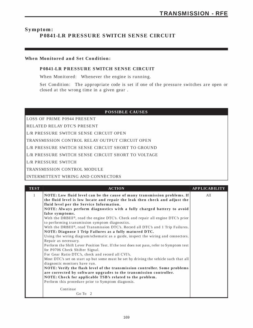
Symptom:P0841-LR PRESSURE SWITCH SENSE CIRCUIT
When Monitored and Set Condition:
P0841-LR PRESSURE SWITCH SENSE CIRCUIT
When Monitored: Whenever the engine is running.
Set Condition: The appropriate code is set if one of the pressure switches are open orclosed at the wrong time in a given gear .
POSSIBLE CAUSES
LOSS OF PRIME P0944 PRESENT
RELATED RELAY DTC’S PRESENT
L/R PRESSURE SWITCH SENSE CIRCUIT OPEN
TRANSMISSION CONTROL RELAY OUTPUT CIRCUIT OPEN
L/R PRESSURE SWITCH SENSE CIRCUIT SHORT TO GROUND
L/R PRESSURE SWITCH SENSE CIRCUIT SHORT TO VOLTAGE
L/R PRESSURE SWITCH
TRANSMISSION CONTROL MODULE
INTERMITTENT WIRING AND CONNECTORS
TEST ACTION APPLICABILITY
1 NOTE: Low fluid level can be the cause of many transmission problems. Ifthe fluid level is low locate and repair the leak then check and adjust thefluid level per the Service Information.NOTE: Always perform diagnostics with a fully charged battery to avoidfalse symptoms.With the DRBIIIt, read the engine DTC’s. Check and repair all engine DTC’s priorto performing transmission symptom diagnostics.With the DRBIIIt, read Transmission DTC’s. Record all DTC’s and 1 Trip Failures.NOTE: Diagnose 1 Trip Failures as a fully matured DTC.Using the wiring diagram/schematic as a guide, inspect the wiring and connectors.Repair as necessary.Perform the Shift Lever Position Test. If the test does not pass, refer to Symptom testfor P0706 Check Shifter Signal.For Gear Ratio DTC’s, check and record all CVI’s.Most DTC’s set on start up but some must be set by driving the vehicle such that alldiagnostic monitors have run.NOTE: Verify the flash level of the transmission controller. Some problemsare corrected by software upgrades to the transmission controller.NOTE: Check for applicable TSB’s related to the problem.Perform this procedure prior to Symptom diagnosis.
All
ContinueGo To 2
169
TRANSMISSION - RFE
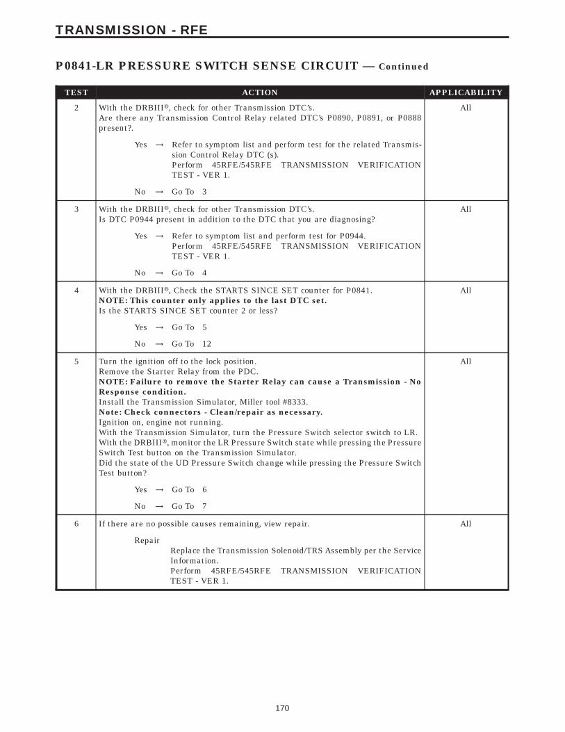
TEST ACTION APPLICABILITY
2 With the DRBIIIt, check for other Transmission DTC’s.Are there any Transmission Control Relay related DTC’s P0890, P0891, or P0888present?.
All
Yes → Refer to symptom list and perform test for the related Transmis-sion Control Relay DTC (s).Perform 45RFE/545RFE TRANSMISSION VERIFICATIONTEST - VER 1.
No → Go To 3
3 With the DRBIIIt, check for other Transmission DTC’s.Is DTC P0944 present in addition to the DTC that you are diagnosing?
All
Yes → Refer to symptom list and perform test for P0944.Perform 45RFE/545RFE TRANSMISSION VERIFICATIONTEST - VER 1.
No → Go To 4
4 With the DRBIIIt, Check the STARTS SINCE SET counter for P0841.NOTE: This counter only applies to the last DTC set.Is the STARTS SINCE SET counter 2 or less?
All
Yes → Go To 5
No → Go To 12
5 Turn the ignition off to the lock position.Remove the Starter Relay from the PDC.NOTE: Failure to remove the Starter Relay can cause a Transmission - NoResponse condition.Install the Transmission Simulator, Miller tool #8333.Note: Check connectors - Clean/repair as necessary.Ignition on, engine not running.With the Transmission Simulator, turn the Pressure Switch selector switch to LR.With the DRBIIIt, monitor the LR Pressure Switch state while pressing the PressureSwitch Test button on the Transmission Simulator.Did the state of the UD Pressure Switch change while pressing the Pressure SwitchTest button?
All
Yes → Go To 6
No → Go To 7
6 If there are no possible causes remaining, view repair. All
RepairReplace the Transmission Solenoid/TRS Assembly per the ServiceInformation.Perform 45RFE/545RFE TRANSMISSION VERIFICATIONTEST - VER 1.
170
TRANSMISSION - RFE
P0841-LR PRESSURE SWITCH SENSE CIRCUIT — Continued
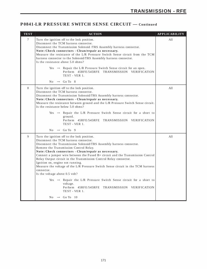
TEST ACTION APPLICABILITY
7 Turn the ignition off to the lock position.Disconnect the TCM harness connector.Disconnect the Transmission Solenoid /TRS Assembly harness connector.Note: Check connectors - Clean/repair as necessary.Measure the resistance of the L/R Pressure Switch Sense circuit from the TCMharness connector to the Solenoid/TRS Assembly harness connector.Is the resistance above 5.0 ohms?
All
Yes → Repair the L/R Pressure Switch Sense circuit for an open.Perform 45RFE/545RFE TRANSMISSION VERIFICATIONTEST - VER 1.
No → Go To 8
8 Turn the ignition off to the lock position.Disconnect the TCM harness connector.Disconnect the Transmission Solenoid/TRS Assembly harness connector.Note: Check connectors - Clean/repair as necessary.Measure the resistance between ground and the L/R Pressure Switch Sense circuit.Is the resistance below 5.0 ohms?
All
Yes → Repair the L/R Pressure Switch Sense circuit for a short toground.Perform 45RFE/545RFE TRANSMISSION VERIFICATIONTEST - VER 1.
No → Go To 9
9 Turn the ignition off to the lock position.Disconnect the TCM harness connector.Disconnect the Transmission Solenoid/TRS Assembly harness connector.Remove the Transmission Control Relay.Note: Check connectors - Clean/repair as necessary.Connect a jumper wire between the Fused B+ circuit and the Transmission ControlRelay Output circuit in the Transmission Control Relay connector.Ignition on, engine not running.Measure the voltage of the L/R Pressure Switch Sense circuit in the TCM harnessconnector.Is the voltage above 0.5 volt?
All
Yes → Repair the L/R Pressure Switch Sense circuit for a short tovoltage.Perform 45RFE/545RFE TRANSMISSION VERIFICATIONTEST - VER 1.
No → Go To 10
171
TRANSMISSION - RFE
P0841-LR PRESSURE SWITCH SENSE CIRCUIT — Continued
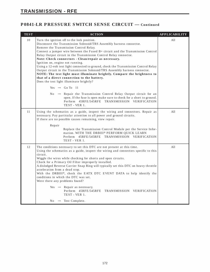
TEST ACTION APPLICABILITY
10 Turn the ignition off to the lock position.Disconnect the Transmission Solenoid/TRS Assembly harness connector.Remove the Transmission Control Relay.Connect a jumper wire between the Fused B+ circuit and the Transmission ControlRelay Output circuit in the Transmission Control Relay connector.Note: Check connectors - Clean/repair as necessary.Ignition on, engine not running.Using a 12-volt test light connected to ground, check the Transmission Control RelayOutput circuit in the Transmission Solenoid/TRS Assembly harness connector.NOTE: The test light must illuminate brightly. Compare the brightness tothat of a direct connection to the battery.Does the test light illuminate brightly?
All
Yes → Go To 11
No → Repair the Transmission Control Relay Output circuit for anopen. If the fuse is open make sure to check for a short to ground.Perform 45RFE/545RFE TRANSMISSION VERIFICATIONTEST - VER 1.
11 Using the schematics as a guide, inspect the wiring and connectors. Repair asnecessary. Pay particular attention to all power and ground circuits.If there are no possible causes remaining, view repair.
All
RepairReplace the Transmission Control Module per the Service Infor-mation. WITH THE DRBIIIt PERFORM QUICK LEARNPerform 45RFE/545RFE TRANSMISSION VERIFICATIONTEST - VER 1.
12 The conditions necessary to set this DTC are not present at this time.Using the schematics as a guide, inspect the wiring and connectors specific to thiscircuit.Wiggle the wires while checking for shorts and open circuits.Check for a Primary Oil Filter improperly installed.A dislodged Reverse Carrier Snap Ring will typically set this DTC on heavy throttleacceleration from a dead stop.With the DRBIIIt, check the EATX DTC EVENT DATA to help identify theconditions in which the DTC was set.Were there any problems found?
All
Yes → Repair as necessary.Perform 45RFE/545RFE TRANSMISSION VERIFICATIONTEST - VER 1.
No → Test Complete.
172
TRANSMISSION - RFE
P0841-LR PRESSURE SWITCH SENSE CIRCUIT — Continued
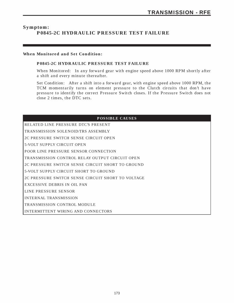
Symptom:P0845-2C HYDRAULIC PRESSURE TEST FAILURE
When Monitored and Set Condition:
P0845-2C HYDRAULIC PRESSURE TEST FAILURE
When Monitored: In any forward gear with engine speed above 1000 RPM shortly aftera shift and every minute thereafter.
Set Condition: After a shift into a forward gear, with engine speed above 1000 RPM, theTCM momentarily turns on element pressure to the Clutch circuits that don’t havepressure to identify the correct Pressure Switch closes. If the Pressure Switch does notclose 2 times, the DTC sets.
POSSIBLE CAUSES
RELATED LINE PRESSURE DTC’S PRESENT
TRANSMISSION SOLENOID/TRS ASSEMBLY
2C PRESSURE SWITCH SENSE CIRCUIT OPEN
5-VOLT SUPPLY CIRCUIT OPEN
POOR LINE PRESSURE SENSOR CONNECTION
TRANSMISSION CONTROL RELAY OUTPUT CIRCUIT OPEN
2C PRESSURE SWITCH SENSE CIRCUIT SHORT TO GROUND
5-VOLT SUPPLY CIRCUIT SHORT TO GROUND
2C PRESSURE SWITCH SENSE CIRCUIT SHORT TO VOLTAGE
EXCESSIVE DEBRIS IN OIL PAN
LINE PRESSURE SENSOR
INTERNAL TRANSMISSION
TRANSMISSION CONTROL MODULE
INTERMITTENT WIRING AND CONNECTORS
173
TRANSMISSION - RFE
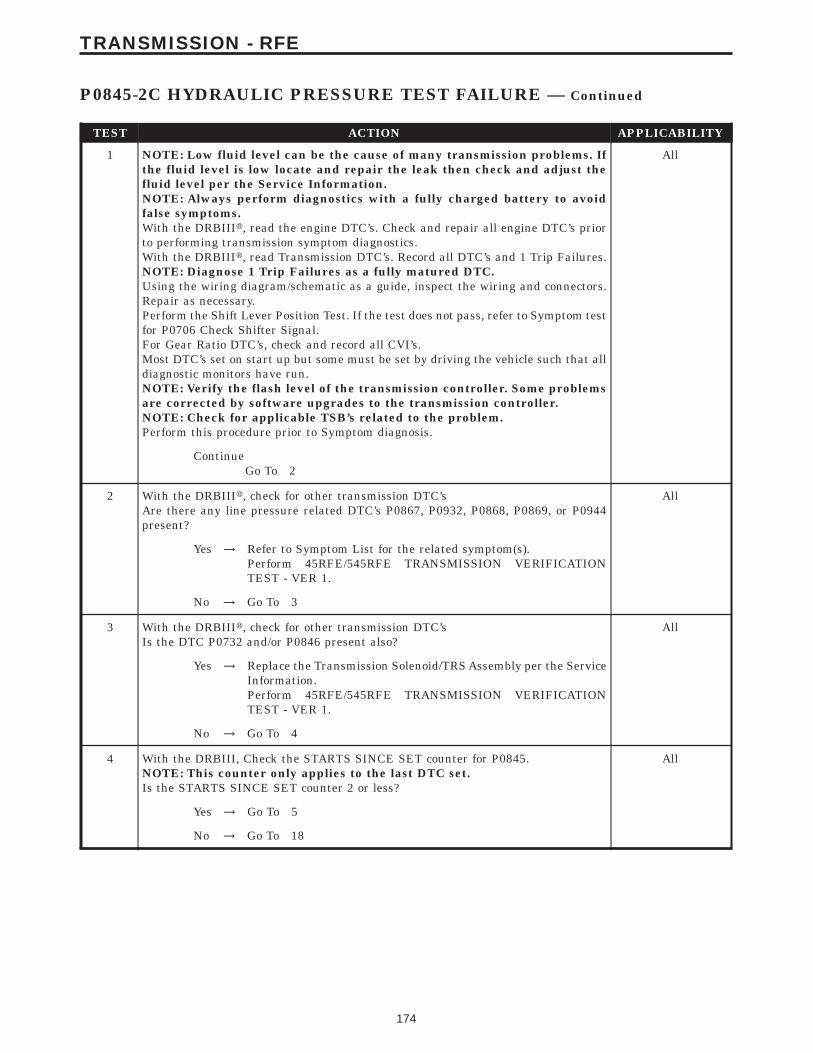
TEST ACTION APPLICABILITY
1 NOTE: Low fluid level can be the cause of many transmission problems. Ifthe fluid level is low locate and repair the leak then check and adjust thefluid level per the Service Information.NOTE: Always perform diagnostics with a fully charged battery to avoidfalse symptoms.With the DRBIIIt, read the engine DTC’s. Check and repair all engine DTC’s priorto performing transmission symptom diagnostics.With the DRBIIIt, read Transmission DTC’s. Record all DTC’s and 1 Trip Failures.NOTE: Diagnose 1 Trip Failures as a fully matured DTC.Using the wiring diagram/schematic as a guide, inspect the wiring and connectors.Repair as necessary.Perform the Shift Lever Position Test. If the test does not pass, refer to Symptom testfor P0706 Check Shifter Signal.For Gear Ratio DTC’s, check and record all CVI’s.Most DTC’s set on start up but some must be set by driving the vehicle such that alldiagnostic monitors have run.NOTE: Verify the flash level of the transmission controller. Some problemsare corrected by software upgrades to the transmission controller.NOTE: Check for applicable TSB’s related to the problem.Perform this procedure prior to Symptom diagnosis.
All
ContinueGo To 2
2 With the DRBIIIt, check for other transmission DTC’sAre there any line pressure related DTC’s P0867, P0932, P0868, P0869, or P0944present?
All
Yes → Refer to Symptom List for the related symptom(s).Perform 45RFE/545RFE TRANSMISSION VERIFICATIONTEST - VER 1.
No → Go To 3
3 With the DRBIIIt, check for other transmission DTC’sIs the DTC P0732 and/or P0846 present also?
All
Yes → Replace the Transmission Solenoid/TRS Assembly per the ServiceInformation.Perform 45RFE/545RFE TRANSMISSION VERIFICATIONTEST - VER 1.
No → Go To 4
4 With the DRBIII, Check the STARTS SINCE SET counter for P0845.NOTE: This counter only applies to the last DTC set.Is the STARTS SINCE SET counter 2 or less?
All
Yes → Go To 5
No → Go To 18
174
TRANSMISSION - RFE
P0845-2C HYDRAULIC PRESSURE TEST FAILURE — Continued
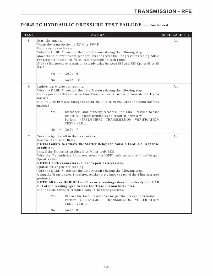
TEST ACTION APPLICABILITY
5 Start the engine.Warm the transmission to 82° C or 180° F.Firmly apply the brakes.With the DRBIIIt, monitor the Line Pressure during the following step.Move the shift lever to each gear position and record the line pressure reading. Allowthe pressure to stabilize for at least 5 seconds in each range.Did the line pressure remain at a steady value between 585 and 655 Kpa or 85 or 95PSI?
All
Yes → Go To 6
No → Go To 10
6 Ignition on, engine not running.With the DRBIIIt, monitor the Line Pressure during the following step.Firmly push the Transmission Line Pressure Sensor connector towards the Trans-mission.Did the Line Pressure change to about 207 kPa or 30 PSI when the connector waspushed?
All
Yes → Disconnect and properly reconnect the Line Pressure Sensorconnector. Inspect terminals and repair as necessary.Perform 45RFE/545RFE TRANSMISSION VERIFICATIONTEST - VER 1.
No → Go To 7
7 Turn the ignition off to the lock position.Remove the Starter Relay.NOTE: Failure to remove the Starter Relay can cause a TCM - No Responsecondition.Install the Transmission Simulator Miller tool# 8333.With the Transmission Simulator select the 9OFF9 position on the 9Input/OutputSpeed9 switch.NOTE: Check connectors - Clean/repair as necessary.Ignition on, engine not running.With the DRBIIIt, monitor the Line Pressure during the following step.Using the Transmission Simulator, set the rotary knob to each of the 3 line pressurepositions.NOTE: All three DRBIIIt Line Pressure readings should be steady and ± 2.0PSI of the reading specified on the Transmission Simulator.Did the Line Pressure remain steady in all three positions?
All
Yes → Replace the Line Pressure Sensor per the Service Information.Perform 45RFE/545RFE TRANSMISSION VERIFICATIONTEST - VER 1.
No → Go To 8
175
TRANSMISSION - RFE
P0845-2C HYDRAULIC PRESSURE TEST FAILURE — Continued

TEST ACTION APPLICABILITY
8 Turn the ignition off to the lock position.Disconnect the TCM harness connector.Disconnect the Line Pressure Sensor harness connector.Note: Check connectors - Clean/repair as necessary.Measure the resistance of the 5-volt Supply circuit from the Line Pressure Sensorharness connector to the TCM harness connector.Is the resistance above 5.0 ohms?
All
Yes → Repair the 5-volt Supply circuit for an open.Perform 45RFE/545RFE TRANSMISSION VERIFICATIONTEST - VER 1.
No → Go To 9
9 Turn the ignition off to the lock position.Disconnect the TCM harness connector.Disconnect the Line Pressure Sensor harness connector.Note: Check connectors - Clean/repair as necessary.Measure the resistance between ground and the 5-volt Supply circuit.Is the resistance below 5.0 ohms?
All
Yes → Repair the 5-volt Supply circuit for a short to ground.Perform 45RFE/545RFE TRANSMISSION VERIFICATIONTEST - VER 1.
No → Go To 17
10 Turn the ignition off to the lock position.Remove the Starter Relay.NOTE: Failure to remove the Starter Relay can cause a Transmission - NoResponse condition.Install the Transmission Simulator, Miller tool # 8333.With the Transmission Simulator, turn the Pressure Switch selector to 2C.Note: Check connectors - Clean/repair as necessary.Ignition on, engine not running.With the DRBIIIt, monitor the 2C Pressure Switch state during the following step.While pressing and holding the Pressure Switch test button, wiggle the wiringharness and connectors pertaining to the 2C Pressure Switch.Did the 2C Pressure Switch state change to closed and remain closed while wigglingthe wires?
All
Yes → Go To 11
No → Go To 13
11 Remove and inspect the Transmission Oil Pan per the Service Information.Does the Transmission Oil Pan contain excessive debris or contamination?
All
Yes → Repair the cause of the excessive debris in the Transmission OilPan. Refer to the Service Information for the proper procedures.Perform 45RFE/545RFE TRANSMISSION VERIFICATIONTEST - VER 1.
No → Go To 12
176
TRANSMISSION - RFE
P0845-2C HYDRAULIC PRESSURE TEST FAILURE — Continued
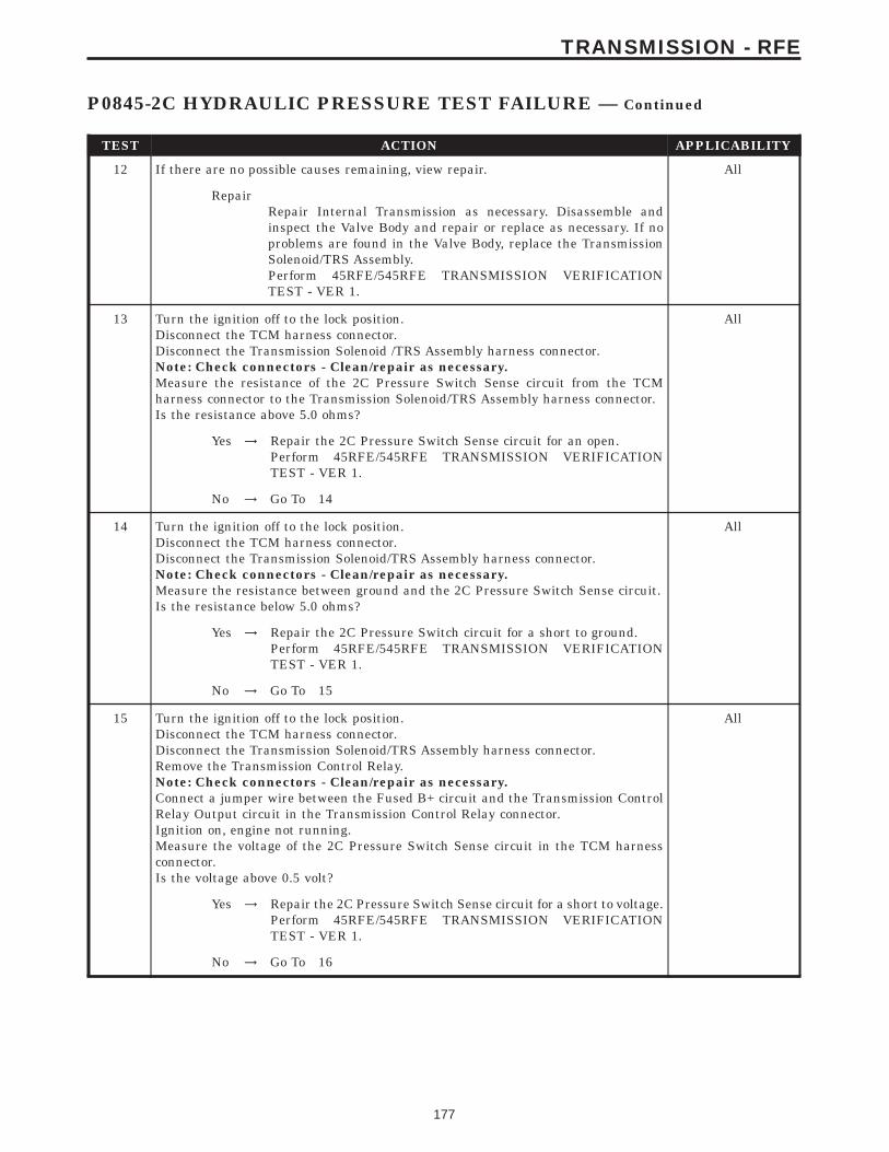
TEST ACTION APPLICABILITY
12 If there are no possible causes remaining, view repair. All
RepairRepair Internal Transmission as necessary. Disassemble andinspect the Valve Body and repair or replace as necessary. If noproblems are found in the Valve Body, replace the TransmissionSolenoid/TRS Assembly.Perform 45RFE/545RFE TRANSMISSION VERIFICATIONTEST - VER 1.
13 Turn the ignition off to the lock position.Disconnect the TCM harness connector.Disconnect the Transmission Solenoid /TRS Assembly harness connector.Note: Check connectors - Clean/repair as necessary.Measure the resistance of the 2C Pressure Switch Sense circuit from the TCMharness connector to the Transmission Solenoid/TRS Assembly harness connector.Is the resistance above 5.0 ohms?
All
Yes → Repair the 2C Pressure Switch Sense circuit for an open.Perform 45RFE/545RFE TRANSMISSION VERIFICATIONTEST - VER 1.
No → Go To 14
14 Turn the ignition off to the lock position.Disconnect the TCM harness connector.Disconnect the Transmission Solenoid/TRS Assembly harness connector.Note: Check connectors - Clean/repair as necessary.Measure the resistance between ground and the 2C Pressure Switch Sense circuit.Is the resistance below 5.0 ohms?
All
Yes → Repair the 2C Pressure Switch circuit for a short to ground.Perform 45RFE/545RFE TRANSMISSION VERIFICATIONTEST - VER 1.
No → Go To 15
15 Turn the ignition off to the lock position.Disconnect the TCM harness connector.Disconnect the Transmission Solenoid/TRS Assembly harness connector.Remove the Transmission Control Relay.Note: Check connectors - Clean/repair as necessary.Connect a jumper wire between the Fused B+ circuit and the Transmission ControlRelay Output circuit in the Transmission Control Relay connector.Ignition on, engine not running.Measure the voltage of the 2C Pressure Switch Sense circuit in the TCM harnessconnector.Is the voltage above 0.5 volt?
All
Yes → Repair the 2C Pressure Switch Sense circuit for a short to voltage.Perform 45RFE/545RFE TRANSMISSION VERIFICATIONTEST - VER 1.
No → Go To 16
177
TRANSMISSION - RFE
P0845-2C HYDRAULIC PRESSURE TEST FAILURE — Continued

TEST ACTION APPLICABILITY
16 Turn the ignition off to the lock position.Disconnect the Transmission Solenoid/TRS Assembly harness connector.Remove the Transmission Control Relay.Connect a jumper wire between the Fused B+ circuit and the Transmission ControlRelay Output circuit in the Transmission Control Relay connector.Ignition on, engine not running.Using a 12-volt test light connected to ground, check the Transmission Control RelayOutput circuit in the Transmission Solenoid/TRS Assembly harness connector.NOTE: The test light must illuminate brightly. Compare the brightness tothat of a direct connection to the battery.Does the test light illuminate brightly?
All
Yes → Go To 17
No → Repair the Transmission Control Relay Output circuit for anopen. If the fuse is open make sure to check for a short to ground.Perform 45RFE/545RFE TRANSMISSION VERIFICATIONTEST - VER 1.
17 Using the schematics as a guide, inspect the wiring and connectors. Repair asnecessary. Pay particular attention to all power and ground circuits.If there are no possible causes remaining, view repair.
All
RepairReplace the Transmission Control Module per the Service Infor-mation. WITH THE DRBIIIt PERFORM QUICK LEARNPerform 45RFE/545RFE TRANSMISSION VERIFICATIONTEST - VER 1.
18 The conditions necessary to set this DTC are not present at this time.Using the schematics as a guide, inspect the wiring and connectors specific to thiscircuit.Wiggle the wires while checking for shorts and open circuits.With the DRBIIIt, check the EATX DTC EVENT DATA to help identify theconditions in which the DTC was set.Were there any problems found?
All
Yes → Repair as necessary.Perform 45RFE/545RFE TRANSMISSION VERIFICATIONTEST - VER 1.
No → Test Complete.
178
TRANSMISSION - RFE
P0845-2C HYDRAULIC PRESSURE TEST FAILURE — Continued
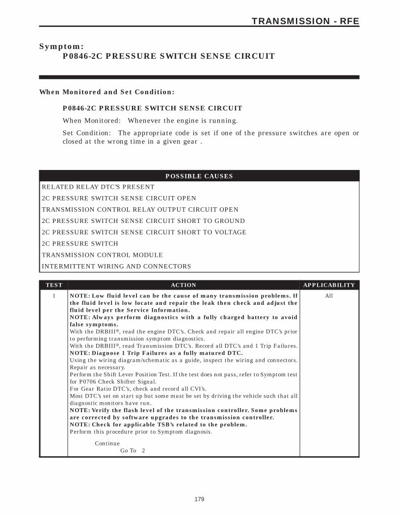
Symptom:P0846-2C PRESSURE SWITCH SENSE CIRCUIT
When Monitored and Set Condition:
P0846-2C PRESSURE SWITCH SENSE CIRCUIT
When Monitored: Whenever the engine is running.
Set Condition: The appropriate code is set if one of the pressure switches are open orclosed at the wrong time in a given gear .
POSSIBLE CAUSES
RELATED RELAY DTC’S PRESENT
2C PRESSURE SWITCH SENSE CIRCUIT OPEN
TRANSMISSION CONTROL RELAY OUTPUT CIRCUIT OPEN
2C PRESSURE SWITCH SENSE CIRCUIT SHORT TO GROUND
2C PRESSURE SWITCH SENSE CIRCUIT SHORT TO VOLTAGE
2C PRESSURE SWITCH
TRANSMISSION CONTROL MODULE
INTERMITTENT WIRING AND CONNECTORS
TEST ACTION APPLICABILITY
1 NOTE: Low fluid level can be the cause of many transmission problems. Ifthe fluid level is low locate and repair the leak then check and adjust thefluid level per the Service Information.NOTE: Always perform diagnostics with a fully charged battery to avoidfalse symptoms.With the DRBIIIt, read the engine DTC’s. Check and repair all engine DTC’s priorto performing transmission symptom diagnostics.With the DRBIIIt, read Transmission DTC’s. Record all DTC’s and 1 Trip Failures.NOTE: Diagnose 1 Trip Failures as a fully matured DTC.Using the wiring diagram/schematic as a guide, inspect the wiring and connectors.Repair as necessary.Perform the Shift Lever Position Test. If the test does not pass, refer to Symptom testfor P0706 Check Shifter Signal.For Gear Ratio DTC’s, check and record all CVI’s.Most DTC’s set on start up but some must be set by driving the vehicle such that alldiagnostic monitors have run.NOTE: Verify the flash level of the transmission controller. Some problemsare corrected by software upgrades to the transmission controller.NOTE: Check for applicable TSB’s related to the problem.Perform this procedure prior to Symptom diagnosis.
All
ContinueGo To 2
179
TRANSMISSION - RFE

TEST ACTION APPLICABILITY
2 With the DRBIIIt, check for other transmission DTC’s.Are there any Transmission Control Relay related DTC’s P0890, P0891, or P0888present?
All
Yes → Refer to symptom list and perform test for Transmission ControlRelay related DTCs.Perform 45RFE/545RFE TRANSMISSION VERIFICATIONTEST - VER 1.
No → Go To 3
3 With the DRBIIIt, Check the STARTS SINCE SET counter.NOTE: This counter only applies to the last DTC set.Is the STARTS SINCE SET counter for P0846, 2 or less?
All
Yes → Go To 4
No → Go To 11
4 Turn the ignition off to the lock position.Remove the Starter Relay.NOTE: Failure to remove the Starter Relay can cause a TCM - No Responsecondition.Install the Transmission Simulator, Miller tool #8333.Note: Check connectors - Clean/repair as necessary.Ignition on, engine not running.With the Transmission Simulator, turn the Pressure Switch selector switch to 2C.With the DRBIIIt, monitor the 2C Pressure Switch while pressing the PressureSwitch test button on the Transmission Simulator.Did the state of the 2C Pressure Switch change while pressing the Pressure SwitchTest button?
All
Yes → Go To 5
No → Go To 6
5 If there are no possible causes remaining, view repair. All
RepairReplace the Transmission Solenoid/TRS Assembly per the ServiceInformation.Perform 45RFE/545RFE TRANSMISSION VERIFICATIONTEST - VER 1.
6 Turn the ignition off to the lock position.Disconnect the TCM harness connector.Disconnect the Transmission Solenoid /TRS Assembly harness connector.Note: Check connectors - Clean/repair as necessary.Measure the resistance of the 2C Pressure Switch Sense circuit from the TCMharness connector to the Transmission Solenoid/TRS Assembly harness connector.Is the resistance above 5.0 ohms?
All
Yes → Repair the 2C Pressure Switch Sense circuit for an open.Perform 45RFE/545RFE TRANSMISSION VERIFICATIONTEST - VER 1.
No → Go To 7
180
TRANSMISSION - RFE
P0846-2C PRESSURE SWITCH SENSE CIRCUIT — Continued
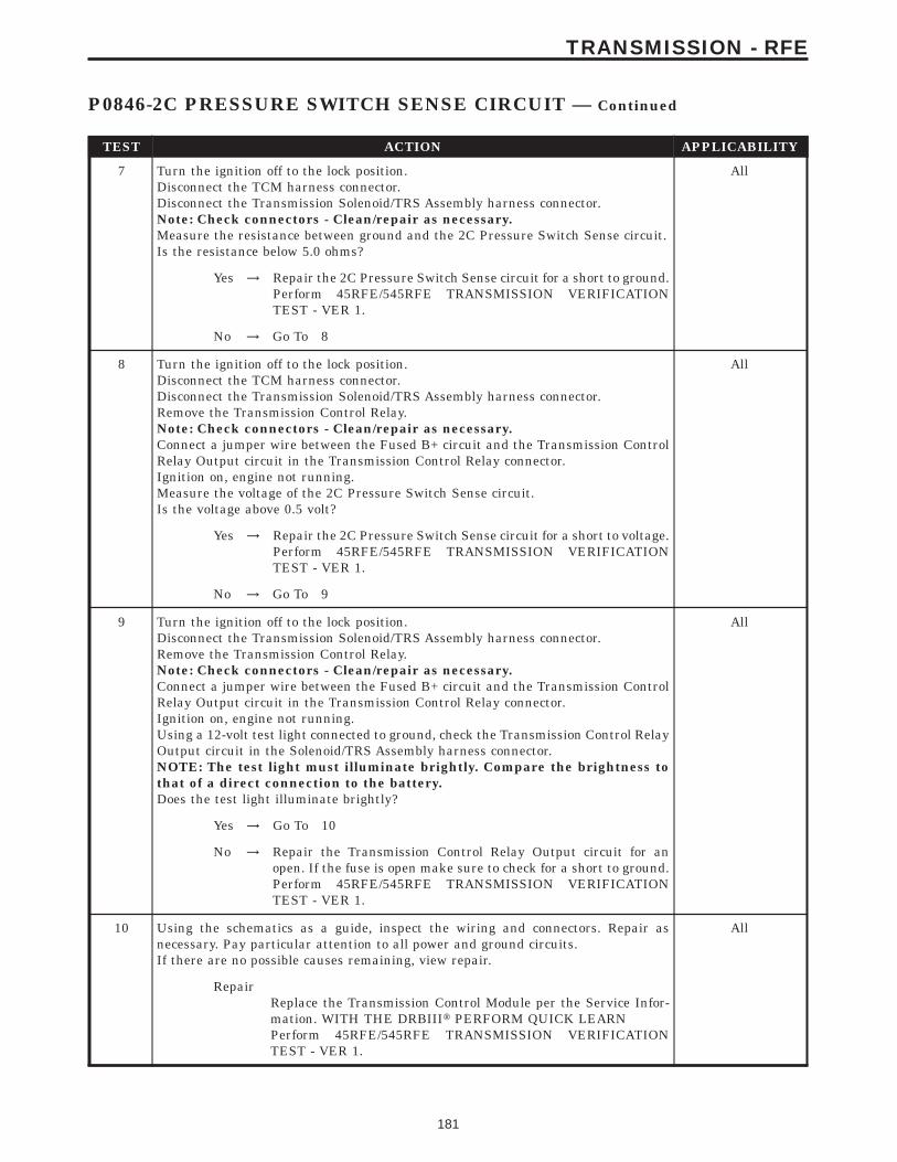
TEST ACTION APPLICABILITY
7 Turn the ignition off to the lock position.Disconnect the TCM harness connector.Disconnect the Transmission Solenoid/TRS Assembly harness connector.Note: Check connectors - Clean/repair as necessary.Measure the resistance between ground and the 2C Pressure Switch Sense circuit.Is the resistance below 5.0 ohms?
All
Yes → Repair the 2C Pressure Switch Sense circuit for a short to ground.Perform 45RFE/545RFE TRANSMISSION VERIFICATIONTEST - VER 1.
No → Go To 8
8 Turn the ignition off to the lock position.Disconnect the TCM harness connector.Disconnect the Transmission Solenoid/TRS Assembly harness connector.Remove the Transmission Control Relay.Note: Check connectors - Clean/repair as necessary.Connect a jumper wire between the Fused B+ circuit and the Transmission ControlRelay Output circuit in the Transmission Control Relay connector.Ignition on, engine not running.Measure the voltage of the 2C Pressure Switch Sense circuit.Is the voltage above 0.5 volt?
All
Yes → Repair the 2C Pressure Switch Sense circuit for a short to voltage.Perform 45RFE/545RFE TRANSMISSION VERIFICATIONTEST - VER 1.
No → Go To 9
9 Turn the ignition off to the lock position.Disconnect the Transmission Solenoid/TRS Assembly harness connector.Remove the Transmission Control Relay.Note: Check connectors - Clean/repair as necessary.Connect a jumper wire between the Fused B+ circuit and the Transmission ControlRelay Output circuit in the Transmission Control Relay connector.Ignition on, engine not running.Using a 12-volt test light connected to ground, check the Transmission Control RelayOutput circuit in the Solenoid/TRS Assembly harness connector.NOTE: The test light must illuminate brightly. Compare the brightness tothat of a direct connection to the battery.Does the test light illuminate brightly?
All
Yes → Go To 10
No → Repair the Transmission Control Relay Output circuit for anopen. If the fuse is open make sure to check for a short to ground.Perform 45RFE/545RFE TRANSMISSION VERIFICATIONTEST - VER 1.
10 Using the schematics as a guide, inspect the wiring and connectors. Repair asnecessary. Pay particular attention to all power and ground circuits.If there are no possible causes remaining, view repair.
All
RepairReplace the Transmission Control Module per the Service Infor-mation. WITH THE DRBIIIt PERFORM QUICK LEARNPerform 45RFE/545RFE TRANSMISSION VERIFICATIONTEST - VER 1.
181
TRANSMISSION - RFE
P0846-2C PRESSURE SWITCH SENSE CIRCUIT — Continued

TEST ACTION APPLICABILITY
11 The conditions necessary to set this DTC are not present at this time.Using the schematics as a guide, inspect the wiring and connectors specific to thiscircuit.Wiggle the wires while checking for shorts and open circuits.Check for a Primary Oil Filter improperly installed.A dislodged Reverse Carrier Snap Ring will typically set this DTC on heavy throttleacceleration from a dead stop.With the DRBIIIt, check the EATX DTC EVENT DATA to help identify theconditions in which the DTC was set.Were there any problems found?
All
Yes → Repair as necessary.Perform 45RFE/545RFE TRANSMISSION VERIFICATIONTEST - VER 1.
No → Test Complete.
182
TRANSMISSION - RFE
P0846-2C PRESSURE SWITCH SENSE CIRCUIT — Continued
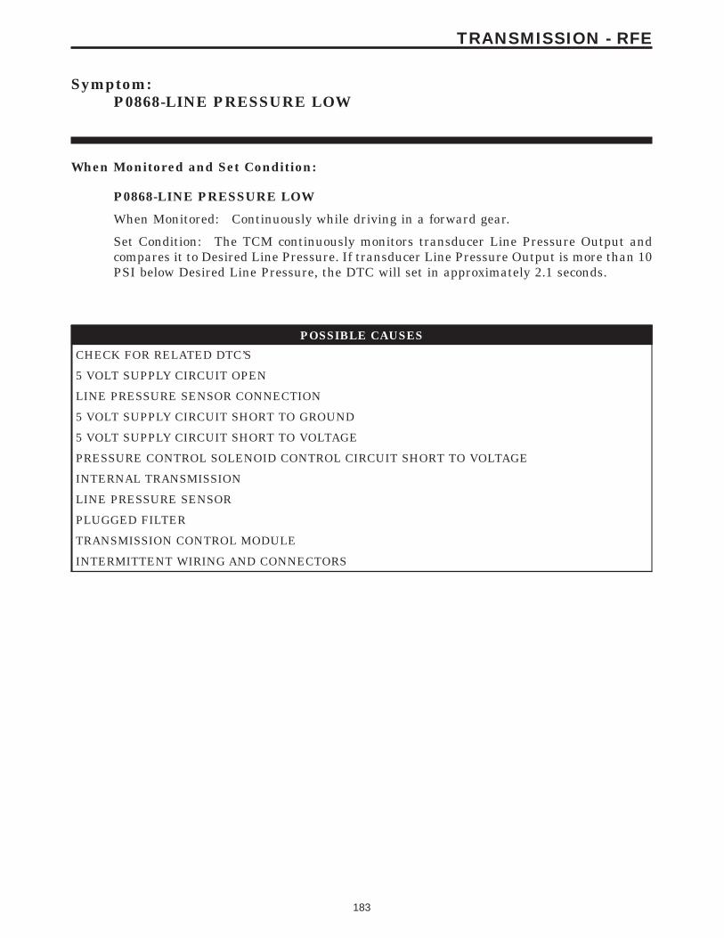
Symptom:P0868-LINE PRESSURE LOW
When Monitored and Set Condition:
P0868-LINE PRESSURE LOW
When Monitored: Continuously while driving in a forward gear.
Set Condition: The TCM continuously monitors transducer Line Pressure Output andcompares it to Desired Line Pressure. If transducer Line Pressure Output is more than 10PSI below Desired Line Pressure, the DTC will set in approximately 2.1 seconds.
POSSIBLE CAUSES
CHECK FOR RELATED DTC’S
5 VOLT SUPPLY CIRCUIT OPEN
LINE PRESSURE SENSOR CONNECTION
5 VOLT SUPPLY CIRCUIT SHORT TO GROUND
5 VOLT SUPPLY CIRCUIT SHORT TO VOLTAGE
PRESSURE CONTROL SOLENOID CONTROL CIRCUIT SHORT TO VOLTAGE
INTERNAL TRANSMISSION
LINE PRESSURE SENSOR
PLUGGED FILTER
TRANSMISSION CONTROL MODULE
INTERMITTENT WIRING AND CONNECTORS
183
TRANSMISSION - RFE
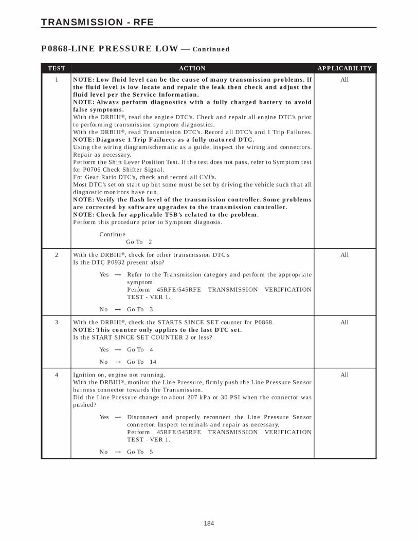
TEST ACTION APPLICABILITY
1 NOTE: Low fluid level can be the cause of many transmission problems. Ifthe fluid level is low locate and repair the leak then check and adjust thefluid level per the Service Information.NOTE: Always perform diagnostics with a fully charged battery to avoidfalse symptoms.With the DRBIIIt, read the engine DTC’s. Check and repair all engine DTC’s priorto performing transmission symptom diagnostics.With the DRBIIIt, read Transmission DTC’s. Record all DTC’s and 1 Trip Failures.NOTE: Diagnose 1 Trip Failures as a fully matured DTC.Using the wiring diagram/schematic as a guide, inspect the wiring and connectors.Repair as necessary.Perform the Shift Lever Position Test. If the test does not pass, refer to Symptom testfor P0706 Check Shifter Signal.For Gear Ratio DTC’s, check and record all CVI’s.Most DTC’s set on start up but some must be set by driving the vehicle such that alldiagnostic monitors have run.NOTE: Verify the flash level of the transmission controller. Some problemsare corrected by software upgrades to the transmission controller.NOTE: Check for applicable TSB’s related to the problem.Perform this procedure prior to Symptom diagnosis.
All
ContinueGo To 2
2 With the DRBIIIt, check for other transmission DTC’sIs the DTC P0932 present also?
All
Yes → Refer to the Transmission category and perform the appropriatesymptom.Perform 45RFE/545RFE TRANSMISSION VERIFICATIONTEST - VER 1.
No → Go To 3
3 With the DRBIIIt, check the STARTS SINCE SET counter for P0868.NOTE: This counter only applies to the last DTC set.Is the START SINCE SET COUNTER 2 or less?
All
Yes → Go To 4
No → Go To 14
4 Ignition on, engine not running.With the DRBIIIt, monitor the Line Pressure, firmly push the Line Pressure Sensorharness connector towards the Transmission.Did the Line Pressure change to about 207 kPa or 30 PSI when the connector waspushed?
All
Yes → Disconnect and properly reconnect the Line Pressure Sensorconnector. Inspect terminals and repair as necessary.Perform 45RFE/545RFE TRANSMISSION VERIFICATIONTEST - VER 1.
No → Go To 5
184
TRANSMISSION - RFE
P0868-LINE PRESSURE LOW — Continued
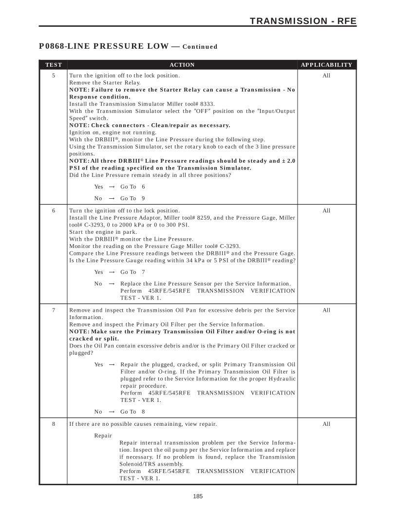
TEST ACTION APPLICABILITY
5 Turn the ignition off to the lock position.Remove the Starter Relay.NOTE: Failure to remove the Starter Relay can cause a Transmission - NoResponse condition.Install the Transmission Simulator Miller tool# 8333.With the Transmission Simulator select the 9OFF9 position on the 9Input/OutputSpeed9 switch.NOTE: Check connectors - Clean/repair as necessary.Ignition on, engine not running.With the DRBIIIt, monitor the Line Pressure during the following step.Using the Transmission Simulator, set the rotary knob to each of the 3 line pressurepositions.NOTE: All three DRBIIIt Line Pressure readings should be steady and ± 2.0PSI of the reading specified on the Transmission Simulator.Did the Line Pressure remain steady in all three positions?
All
Yes → Go To 6
No → Go To 9
6 Turn the ignition off to the lock position.Install the Line Pressure Adaptor, Miller tool# 8259, and the Pressure Gage, Millertool# C-3293, 0 to 2000 kPa or 0 to 300 PSI.Start the engine in park.With the DRBIIIt monitor the Line Pressure.Monitor the reading on the Pressure Gage Miller tool# C-3293.Compare the Line Pressure readings between the DRBIIIt and the Pressure Gage.Is the Line Pressure Gauge reading within 34 kPa or 5 PSI of the DRBIIIt reading?
All
Yes → Go To 7
No → Replace the Line Pressure Sensor per the Service Information.Perform 45RFE/545RFE TRANSMISSION VERIFICATIONTEST - VER 1.
7 Remove and inspect the Transmission Oil Pan for excessive debris per the ServiceInformation.Remove and inspect the Primary Oil Filter per the Service Information.NOTE: Make sure the Primary Transmission Oil Filter and/or O-ring is notcracked or split.Does the Oil Pan contain excessive debris and/or is the Primary Oil Filter cracked orplugged?
All
Yes → Repair the plugged, cracked, or split Primary Transmission OilFilter and/or O-ring. If the Primary Transmission Oil Filter isplugged refer to the Service Information for the proper Hydraulicrepair procedure.Perform 45RFE/545RFE TRANSMISSION VERIFICATIONTEST - VER 1.
No → Go To 8
8 If there are no possible causes remaining, view repair. All
RepairRepair internal transmission problem per the Service Informa-tion. Inspect the oil pump per the Service Information and replaceif necessary. If no problem is found, replace the TransmissionSolenoid/TRS assembly.Perform 45RFE/545RFE TRANSMISSION VERIFICATIONTEST - VER 1.
185
TRANSMISSION - RFE
P0868-LINE PRESSURE LOW — Continued
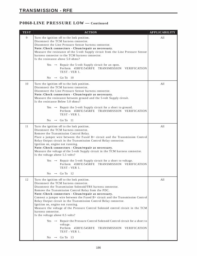
TEST ACTION APPLICABILITY
9 Turn the ignition off to the lock position.Disconnect the TCM harness connector.Disconnect the Line Pressure Sensor harness connector.Note: Check connectors - Clean/repair as necessary.Measure the resistance of the 5-volt Supply circuit from the Line Pressure Sensorharness connector to the TCM harness connector.Is the resistance above 5.0 ohms?
All
Yes → Repair the 5-volt Supply circuit for an open.Perform 45RFE/545RFE TRANSMISSION VERIFICATIONTEST - VER 1.
No → Go To 10
10 Turn the ignition off to the lock position.Disconnect the TCM harness connector.Disconnect the Line Pressure Sensor harness connector.Note: Check connectors - Clean/repair as necessary.Measure the resistance between ground and the 5-volt Supply circuit.Is the resistance Below 5.0 ohms?
All
Yes → Repair the 5-volt Supply circuit for a short to ground.Perform 45RFE/545RFE TRANSMISSION VERIFICATIONTEST - VER 1.
No → Go To 11
11 Turn the ignition off to the lock position.Disconnect the TCM harness connector.Remove the Transmission Control Relay.Place a jumper wire between the Fused B+ circuit and the Transmission ControlRelay Output circuit in the Transmission Control Relay connector.Ignition on, engine not running.Note: Check connectors - Clean/repair as necessary.Measure the voltage of the 5-volt Supply circuit in the TCM harness connector.Is the voltage above 5.5 volts?
All
Yes → Repair the 5-volt Supply circuit for a short to voltage.Perform 45RFE/545RFE TRANSMISSION VERIFICATIONTEST - VER 1.
No → Go To 12
12 Turn the ignition off to the lock position.Disconnect the TCM harness connector.Disconnect the Transmission Solenoid/TRS harness connector.Remove the Transmission Control Relay from the PDC.Note: Check connectors - Clean/repair as necessary.Connect a jumper wire between the Fused B+ circuit and the Transmission ControlRelay Output circuit in the Transmission Control Relay connector.Ignition on, engine not running.Measure the voltage of the Pressure Control Solenoid control circuit in the TCMharness connector.Is the voltage above 0.5 volts?
All
Yes → Repair the Pressure Control Solenoid Control circuit for a short tovoltage.Perform 45RFE/545RFE TRANSMISSION VERIFICATIONTEST - VER 1.
No → Go To 13
186
TRANSMISSION - RFE
P0868-LINE PRESSURE LOW — Continued
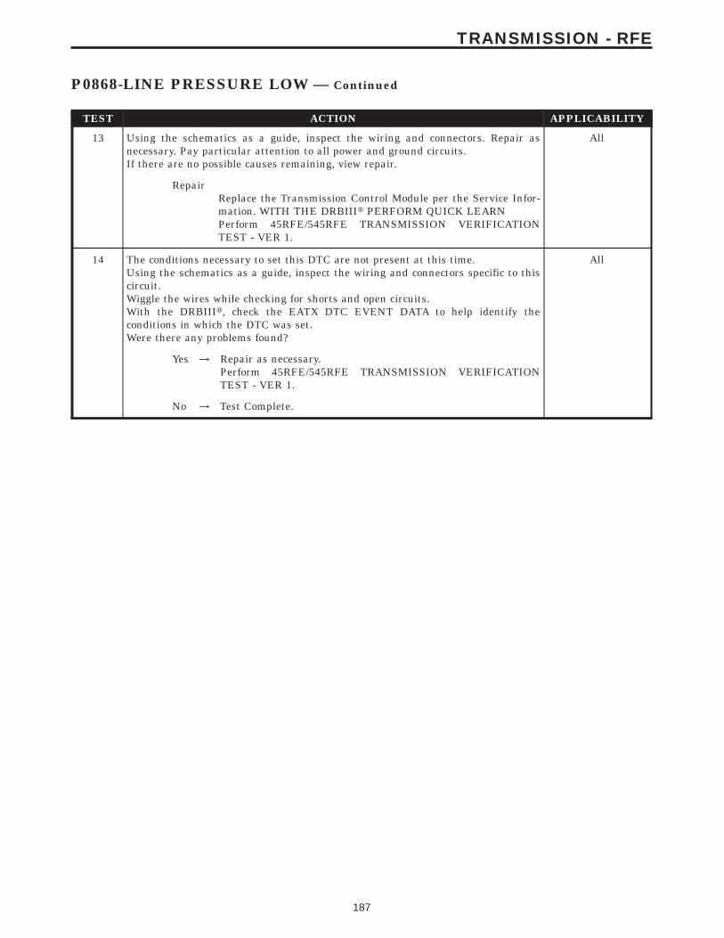
TEST ACTION APPLICABILITY
13 Using the schematics as a guide, inspect the wiring and connectors. Repair asnecessary. Pay particular attention to all power and ground circuits.If there are no possible causes remaining, view repair.
All
RepairReplace the Transmission Control Module per the Service Infor-mation. WITH THE DRBIIIt PERFORM QUICK LEARNPerform 45RFE/545RFE TRANSMISSION VERIFICATIONTEST - VER 1.
14 The conditions necessary to set this DTC are not present at this time.Using the schematics as a guide, inspect the wiring and connectors specific to thiscircuit.Wiggle the wires while checking for shorts and open circuits.With the DRBIIIt, check the EATX DTC EVENT DATA to help identify theconditions in which the DTC was set.Were there any problems found?
All
Yes → Repair as necessary.Perform 45RFE/545RFE TRANSMISSION VERIFICATIONTEST - VER 1.
No → Test Complete.
187
TRANSMISSION - RFE
P0868-LINE PRESSURE LOW — Continued
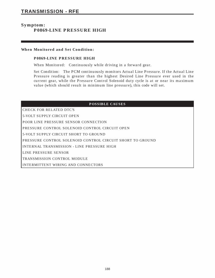
Symptom:P0869-LINE PRESSURE HIGH
When Monitored and Set Condition:
P0869-LINE PRESSURE HIGH
When Monitored: Continuously while driving in a forward gear.
Set Condition: The PCM continuously monitors Actual Line Pressure. If the Actual LinePressure reading is greater than the highest Desired Line Pressure ever used in thecurrent gear, while the Pressure Control Solenoid duty cycle is at or near its maximumvalue (which should result in minimum line pressure), this code will set.
POSSIBLE CAUSES
CHECK FOR RELATED DTC’S
5-VOLT SUPPLY CIRCUIT OPEN
POOR LINE PRESSURE SENSOR CONNECTION
PRESSURE CONTROL SOLENOID CONTROL CIRCUIT OPEN
5-VOLT SUPPLY CIRCUIT SHORT TO GROUND
PRESSURE CONTROL SOLENOID CONTROL CIRCUIT SHORT TO GROUND
INTERNAL TRANSMISSION - LINE PRESSURE HIGH
LINE PRESSURE SENSOR
TRANSMISSION CONTROL MODULE
INTERMITTENT WIRING AND CONNECTORS
188
TRANSMISSION - RFE
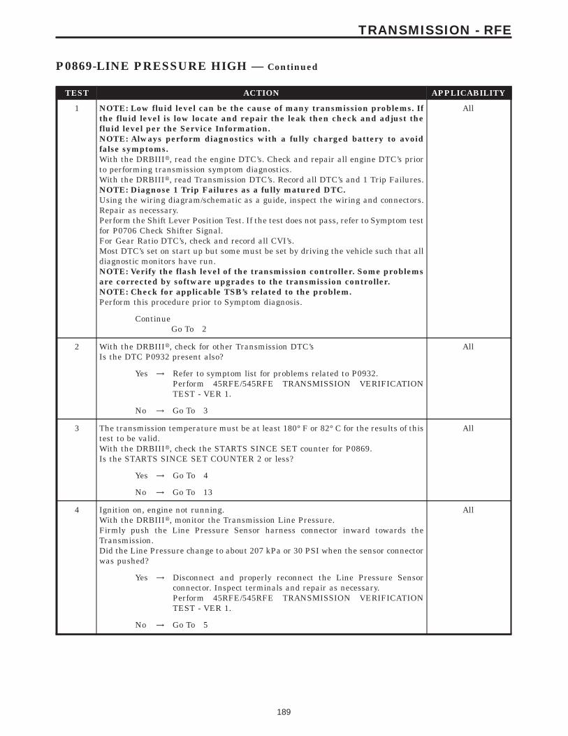
TEST ACTION APPLICABILITY
1 NOTE: Low fluid level can be the cause of many transmission problems. Ifthe fluid level is low locate and repair the leak then check and adjust thefluid level per the Service Information.NOTE: Always perform diagnostics with a fully charged battery to avoidfalse symptoms.With the DRBIIIt, read the engine DTC’s. Check and repair all engine DTC’s priorto performing transmission symptom diagnostics.With the DRBIIIt, read Transmission DTC’s. Record all DTC’s and 1 Trip Failures.NOTE: Diagnose 1 Trip Failures as a fully matured DTC.Using the wiring diagram/schematic as a guide, inspect the wiring and connectors.Repair as necessary.Perform the Shift Lever Position Test. If the test does not pass, refer to Symptom testfor P0706 Check Shifter Signal.For Gear Ratio DTC’s, check and record all CVI’s.Most DTC’s set on start up but some must be set by driving the vehicle such that alldiagnostic monitors have run.NOTE: Verify the flash level of the transmission controller. Some problemsare corrected by software upgrades to the transmission controller.NOTE: Check for applicable TSB’s related to the problem.Perform this procedure prior to Symptom diagnosis.
All
ContinueGo To 2
2 With the DRBIIIt, check for other Transmission DTC’sIs the DTC P0932 present also?
All
Yes → Refer to symptom list for problems related to P0932.Perform 45RFE/545RFE TRANSMISSION VERIFICATIONTEST - VER 1.
No → Go To 3
3 The transmission temperature must be at least 180° F or 82° C for the results of thistest to be valid.With the DRBIIIt, check the STARTS SINCE SET counter for P0869.Is the STARTS SINCE SET COUNTER 2 or less?
All
Yes → Go To 4
No → Go To 13
4 Ignition on, engine not running.With the DRBIIIt, monitor the Transmission Line Pressure.Firmly push the Line Pressure Sensor harness connector inward towards theTransmission.Did the Line Pressure change to about 207 kPa or 30 PSI when the sensor connectorwas pushed?
All
Yes → Disconnect and properly reconnect the Line Pressure Sensorconnector. Inspect terminals and repair as necessary.Perform 45RFE/545RFE TRANSMISSION VERIFICATIONTEST - VER 1.
No → Go To 5
189
TRANSMISSION - RFE
P0869-LINE PRESSURE HIGH — Continued
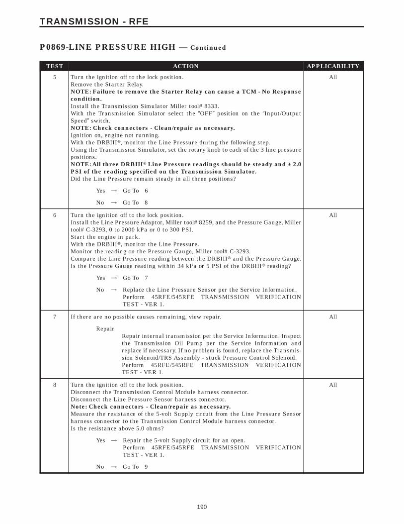
TEST ACTION APPLICABILITY
5 Turn the ignition off to the lock position.Remove the Starter Relay.NOTE: Failure to remove the Starter Relay can cause a TCM - No Responsecondition.Install the Transmission Simulator Miller tool# 8333.With the Transmission Simulator select the 9OFF9 position on the 9Input/OutputSpeed9 switch.NOTE: Check connectors - Clean/repair as necessary.Ignition on, engine not running.With the DRBIIIt, monitor the Line Pressure during the following step.Using the Transmission Simulator, set the rotary knob to each of the 3 line pressurepositions.NOTE: All three DRBIIIt Line Pressure readings should be steady and ± 2.0PSI of the reading specified on the Transmission Simulator.Did the Line Pressure remain steady in all three positions?
All
Yes → Go To 6
No → Go To 8
6 Turn the ignition off to the lock position.Install the Line Pressure Adaptor, Miller tool# 8259, and the Pressure Gauge, Millertool# C-3293, 0 to 2000 kPa or 0 to 300 PSI.Start the engine in park.With the DRBIIIt, monitor the Line Pressure.Monitor the reading on the Pressure Gauge, Miller tool# C-3293.Compare the Line Pressure reading between the DRBIIIt and the Pressure Gauge.Is the Pressure Gauge reading within 34 kPa or 5 PSI of the DRBIIIt reading?
All
Yes → Go To 7
No → Replace the Line Pressure Sensor per the Service Information.Perform 45RFE/545RFE TRANSMISSION VERIFICATIONTEST - VER 1.
7 If there are no possible causes remaining, view repair. All
RepairRepair internal transmission per the Service Information. Inspectthe Transmission Oil Pump per the Service Information andreplace if necessary. If no problem is found, replace the Transmis-sion Solenoid/TRS Assembly - stuck Pressure Control Solenoid.Perform 45RFE/545RFE TRANSMISSION VERIFICATIONTEST - VER 1.
8 Turn the ignition off to the lock position.Disconnect the Transmission Control Module harness connector.Disconnect the Line Pressure Sensor harness connector.Note: Check connectors - Clean/repair as necessary.Measure the resistance of the 5-volt Supply circuit from the Line Pressure Sensorharness connector to the Transmission Control Module harness connector.Is the resistance above 5.0 ohms?
All
Yes → Repair the 5-volt Supply circuit for an open.Perform 45RFE/545RFE TRANSMISSION VERIFICATIONTEST - VER 1.
No → Go To 9
190
TRANSMISSION - RFE
P0869-LINE PRESSURE HIGH — Continued
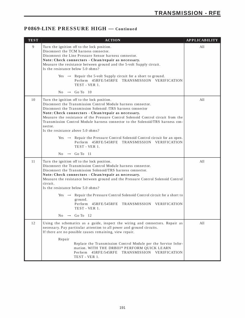
TEST ACTION APPLICABILITY
9 Turn the ignition off to the lock position.Disconnect the TCM harness connector.Disconnect the Line Pressure Sensor harness connector.Note: Check connectors - Clean/repair as necessary.Measure the resistance between ground and the 5-volt Supply circuit.Is the resistance below 5.0 ohms?
All
Yes → Repair the 5-volt Supply circuit for a short to ground.Perform 45RFE/545RFE TRANSMISSION VERIFICATIONTEST - VER 1.
No → Go To 10
10 Turn the ignition off to the lock position.Disconnect the Transmission Control Module harness connector.Disconnect the Transmission Solenoid /TRS harness connectorNote: Check connectors - Clean/repair as necessary.Measure the resistance of the Pressure Control Solenoid Control circuit from theTransmission Control Module harness connector to the Solenoid/TRS harness con-nector.Is the resistance above 5.0 ohms?
All
Yes → Repair the Pressure Control Solenoid Control circuit for an open.Perform 45RFE/545RFE TRANSMISSION VERIFICATIONTEST - VER 1.
No → Go To 11
11 Turn the ignition off to the lock position.Disconnect the Transmission Control Module harness connector.Disconnect the Transmission Solenoid/TRS harness connector.Note: Check connectors - Clean/repair as necessary.Measure the resistance between ground and the Pressure Control Solenoid Controlcircuit.Is the resistance below 5.0 ohms?
All
Yes → Repair the Pressure Control Solenoid Control circuit for a short toground.Perform 45RFE/545RFE TRANSMISSION VERIFICATIONTEST - VER 1.
No → Go To 12
12 Using the schematics as a guide, inspect the wiring and connectors. Repair asnecessary. Pay particular attention to all power and ground circuits.If there are no possible causes remaining, view repair.
All
RepairReplace the Transmission Control Module per the Service Infor-mation. WITH THE DRBIIIt PERFORM QUICK LEARNPerform 45RFE/545RFE TRANSMISSION VERIFICATIONTEST - VER 1.
191
TRANSMISSION - RFE
P0869-LINE PRESSURE HIGH — Continued
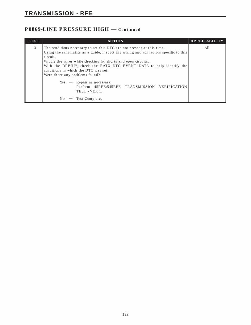
TEST ACTION APPLICABILITY
13 The conditions necessary to set this DTC are not present at this time.Using the schematics as a guide, inspect the wiring and connectors specific to thiscircuit.Wiggle the wires while checking for shorts and open circuits.With the DRBIIIt, check the EATX DTC EVENT DATA to help identify theconditions in which the DTC was set.Were there any problems found?
All
Yes → Repair as necessary.Perform 45RFE/545RFE TRANSMISSION VERIFICATIONTEST - VER 1.
No → Test Complete.
192
TRANSMISSION - RFE
P0869-LINE PRESSURE HIGH — Continued
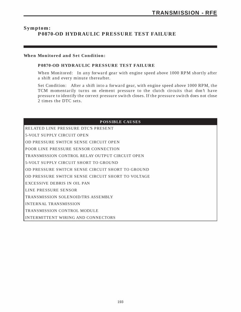
Symptom:P0870-OD HYDRAULIC PRESSURE TEST FAILURE
When Monitored and Set Condition:
P0870-OD HYDRAULIC PRESSURE TEST FAILURE
When Monitored: In any forward gear with engine speed above 1000 RPM shortly aftera shift and every minute thereafter.
Set Condition: After a shift into a forward gear, with engine speed above 1000 RPM, theTCM momentarily turns on element pressure to the clutch circuits that don’t havepressure to identify the correct pressure switch closes. If the pressure switch does not close2 times the DTC sets.
POSSIBLE CAUSES
RELATED LINE PRESSURE DTC’S PRESENT
5-VOLT SUPPLY CIRCUIT OPEN
OD PRESSURE SWITCH SENSE CIRCUIT OPEN
POOR LINE PRESSURE SENSOR CONNECTION
TRANSMISSION CONTROL RELAY OUTPUT CIRCUIT OPEN
5-VOLT SUPPLY CIRCUIT SHORT TO GROUND
OD PRESSURE SWITCH SENSE CIRCUIT SHORT TO GROUND
OD PRESSURE SWITCH SENSE CIRCUIT SHORT TO VOLTAGE
EXCESSIVE DEBRIS IN OIL PAN
LINE PRESSURE SENSOR
TRANSMISSION SOLENOID/TRS ASSEMBLY
INTERNAL TRANSMISSION
TRANSMISSION CONTROL MODULE
INTERMITTENT WIRING AND CONNECTORS
193
TRANSMISSION - RFE

TEST ACTION APPLICABILITY
1 NOTE: Low fluid level can be the cause of many transmission problems. Ifthe fluid level is low locate and repair the leak then check and adjust thefluid level per the Service Information.NOTE: Always perform diagnostics with a fully charged battery to avoidfalse symptoms.With the DRBIIIt, read the engine DTC’s. Check and repair all engine DTC’s priorto performing transmission symptom diagnostics.With the DRBIIIt, read Transmission DTC’s. Record all DTC’s and 1 Trip Failures.NOTE: Diagnose 1 Trip Failures as a fully matured DTC.Using the wiring diagram/schematic as a guide, inspect the wiring and connectors.Repair as necessary.Perform the Shift Lever Position Test. If the test does not pass, refer to Symptom testfor P0706 Check Shifter Signal.For Gear Ratio DTC’s, check and record all CVI’s.Most DTC’s set on start up but some must be set by driving the vehicle such that alldiagnostic monitors have run.NOTE: Verify the flash level of the transmission controller. Some problemsare corrected by software upgrades to the transmission controller.NOTE: Check for applicable TSB’s related to the problem.Perform this procedure prior to Symptom diagnosis.
All
ContinueGo To 2
2 With the DRBIIIt, check for other Transmission DTC’s.Are there any Line Pressure related DTC’s P0867, P0932, P0868, P0869, or P0944present?
All
Yes → Refer to symptom list and perform appropriate test.Perform 45RFE/545RFE TRANSMISSION VERIFICATIONTEST - VER 1.
No → Go To 3
3 With the DRBIIIt, check for other Transmission DTC’s.Is the DTC P0733 and/or P0871 present also?
All
Yes → Replace the Transmission Solenoid/TRS Assembly per the ServiceInformation.Perform 45RFE/545RFE TRANSMISSION VERIFICATIONTEST - VER 1.
No → Go To 4
4 With the DRBIIIt, Check the STARTS SINCE SET counter for P0870.NOTE: This counter only applies to the last DTC set.Is the STARTS SINCE SET counter 2 or less?
All
Yes → Go To 5
No → Go To 18
194
TRANSMISSION - RFE
P0870-OD HYDRAULIC PRESSURE TEST FAILURE — Continued
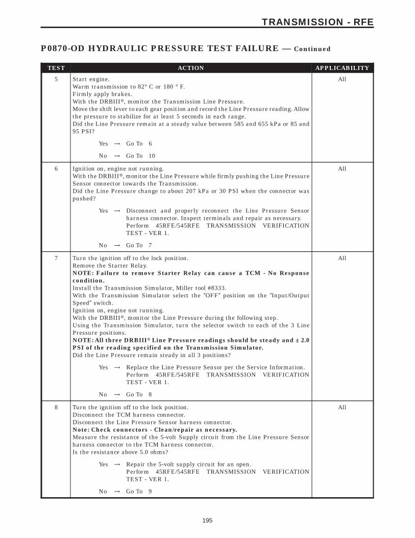
TEST ACTION APPLICABILITY
5 Start engine.Warm transmission to 82° C or 180 ° F.Firmly apply brakes.With the DRBIIIt, monitor the Transmission Line Pressure.Move the shift lever to each gear position and record the Line Pressure reading. Allowthe pressure to stabilize for at least 5 seconds in each range.Did the Line Pressure remain at a steady value between 585 and 655 kPa or 85 and95 PSI?
All
Yes → Go To 6
No → Go To 10
6 Ignition on, engine not running.With the DRBIIIt, monitor the Line Pressure while firmly pushing the Line PressureSensor connector towards the Transmission.Did the Line Pressure change to about 207 kPa or 30 PSI when the connector waspushed?
All
Yes → Disconnect and properly reconnect the Line Pressure Sensorharness connector. Inspect terminals and repair as necessary.Perform 45RFE/545RFE TRANSMISSION VERIFICATIONTEST - VER 1.
No → Go To 7
7 Turn the ignition off to the lock position.Remove the Starter Relay.NOTE: Failure to remove Starter Relay can cause a TCM - No Responsecondition.Install the Transmission Simulator, Miller tool #8333.With the Transmission Simulator select the 9OFF9 position on the 9Input/OutputSpeed9 switch.Ignition on, engine not running.With the DRBIIIt, monitor the Line Pressure during the following step.Using the Transmission Simulator, turn the selector switch to each of the 3 LinePressure positions.NOTE: All three DRBIIIt Line Pressure readings should be steady and ± 2.0PSI of the reading specified on the Transmission Simulator.Did the Line Pressure remain steady in all 3 positions?
All
Yes → Replace the Line Pressure Sensor per the Service Information.Perform 45RFE/545RFE TRANSMISSION VERIFICATIONTEST - VER 1.
No → Go To 8
8 Turn the ignition off to the lock position.Disconnect the TCM harness connector.Disconnect the Line Pressure Sensor harness connector.Note: Check connectors - Clean/repair as necessary.Measure the resistance of the 5-volt Supply circuit from the Line Pressure Sensorharness connector to the TCM harness connector.Is the resistance above 5.0 ohms?
All
Yes → Repair the 5-volt supply circuit for an open.Perform 45RFE/545RFE TRANSMISSION VERIFICATIONTEST - VER 1.
No → Go To 9
195
TRANSMISSION - RFE
P0870-OD HYDRAULIC PRESSURE TEST FAILURE — Continued
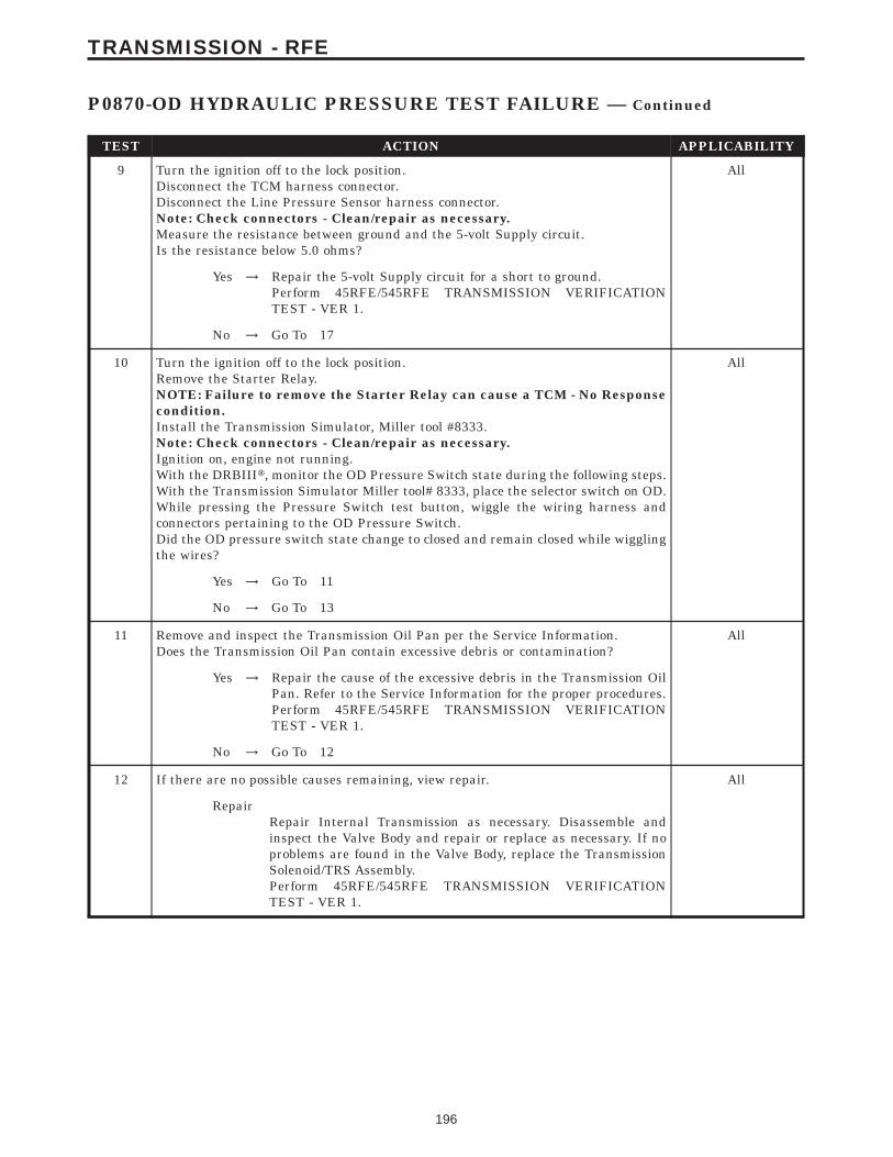
TEST ACTION APPLICABILITY
9 Turn the ignition off to the lock position.Disconnect the TCM harness connector.Disconnect the Line Pressure Sensor harness connector.Note: Check connectors - Clean/repair as necessary.Measure the resistance between ground and the 5-volt Supply circuit.Is the resistance below 5.0 ohms?
All
Yes → Repair the 5-volt Supply circuit for a short to ground.Perform 45RFE/545RFE TRANSMISSION VERIFICATIONTEST - VER 1.
No → Go To 17
10 Turn the ignition off to the lock position.Remove the Starter Relay.NOTE: Failure to remove the Starter Relay can cause a TCM - No Responsecondition.Install the Transmission Simulator, Miller tool #8333.Note: Check connectors - Clean/repair as necessary.Ignition on, engine not running.With the DRBIIIt, monitor the OD Pressure Switch state during the following steps.With the Transmission Simulator Miller tool# 8333, place the selector switch on OD.While pressing the Pressure Switch test button, wiggle the wiring harness andconnectors pertaining to the OD Pressure Switch.Did the OD pressure switch state change to closed and remain closed while wigglingthe wires?
All
Yes → Go To 11
No → Go To 13
11 Remove and inspect the Transmission Oil Pan per the Service Information.Does the Transmission Oil Pan contain excessive debris or contamination?
All
Yes → Repair the cause of the excessive debris in the Transmission OilPan. Refer to the Service Information for the proper procedures.Perform 45RFE/545RFE TRANSMISSION VERIFICATIONTEST - VER 1.
No → Go To 12
12 If there are no possible causes remaining, view repair. All
RepairRepair Internal Transmission as necessary. Disassemble andinspect the Valve Body and repair or replace as necessary. If noproblems are found in the Valve Body, replace the TransmissionSolenoid/TRS Assembly.Perform 45RFE/545RFE TRANSMISSION VERIFICATIONTEST - VER 1.
196
TRANSMISSION - RFE
P0870-OD HYDRAULIC PRESSURE TEST FAILURE — Continued

TEST ACTION APPLICABILITY
13 Turn the ignition off to the lock position.Disconnect the TCM harness connector.Disconnect the Transmission Solenoid /TRS Assembly harness connectorNote: Check connectors - Clean/repair as necessary.Measure the resistance of the OD Pressure Switch Sense circuit from the TCMharness connector to the Transmission Solenoid/TRS Assembly harness connector.Is the resistance above 5.0 ohms?
All
Yes → Repair the OD Pressure Switch Sense circuit for an open.Perform 45RFE/545RFE TRANSMISSION VERIFICATIONTEST - VER 1.
No → Go To 14
14 Turn the ignition off to the lock position.Disconnect the TCM harness connector.Disconnect the Transmission Solenoid/TRS Assembly harness connector.Note: Check connectors - Clean/repair as necessary.Measure the resistance between ground and the OD Pressure Switch Sense circuit.Is the resistance below 5.0 ohms?
All
Yes → Repair the OD Pressure Switch Sense circuit for a short toground.Perform 45RFE/545RFE TRANSMISSION VERIFICATIONTEST - VER 1.
No → Go To 15
15 Turn the ignition off to the lock position.Disconnect the TCM harness connector.Disconnect the Transmission Solenoid/TRS Assembly harness connector.Remove the Transmission Control Relay.Note: Check connectors - Clean/repair as necessary.Connect a jumper wire between the Fused B+ circuit and the Transmission ControlRelay Output circuit in the Transmission Control Relay connector.Ignition on, engine not running.Measure the voltage of the OD Pressure Switch Sense circuit in the TCM harnessconnector.Is the voltage above 0.5 volt?
All
Yes → Repair the OD Pressure Switch Sense circuit for a short tovoltage.Perform 45RFE/545RFE TRANSMISSION VERIFICATIONTEST - VER 1.
No → Go To 16
197
TRANSMISSION - RFE
P0870-OD HYDRAULIC PRESSURE TEST FAILURE — Continued

TEST ACTION APPLICABILITY
16 Turn the ignition off to the lock position.Disconnect the Transmission Solenoid/TRS Assembly harness connector.Remove the Transmission Control Relay.Connect a jumper wire between the Fused B(+) circuit and the Transmission ControlRelay Output circuit in the Transmission Control Relay connector.Ignition on, engine not running.Using a 12-volt test light connected to ground, check the Transmission Control RelayOutput circuit at the Transmission Solenoid/TRS Assembly harness connector.NOTE: The test light must illuminate brightly. Compare the brightness tothat of a direct connection to the battery.Does the test light illuminate brightly?
All
Yes → Go To 17
No → Repair the Transmission Control Relay Output circuit for anopen. If the fuse is open make sure to check for a short to ground.Perform 45RFE/545RFE TRANSMISSION VERIFICATIONTEST - VER 1.
17 Using the schematics as a guide, inspect the wiring and connectors. Repair asnecessary. Pay particular attention to all power and ground circuits.If there are no possible causes remaining, view repair.
All
RepairReplace the Transmission Control Module per the Service Infor-mation. WITH THE DRBIIIt PERFORM QUICK LEARNPerform 45RFE/545RFE TRANSMISSION VERIFICATIONTEST - VER 1.
18 The conditions necessary to set this DTC are not present at this time.Using the schematics as a guide, inspect the wiring and connectors specific to thiscircuit.Wiggle the wires while checking for shorts and open circuits.With the DRBIIIt, check the EATX DTC EVENT DATA to help identify theconditions in which the DTC was set.Were there any problems found?
All
Yes → Repair as necessary.Perform 45RFE/545RFE TRANSMISSION VERIFICATIONTEST - VER 1.
No → Test Complete.
198
TRANSMISSION - RFE
P0870-OD HYDRAULIC PRESSURE TEST FAILURE — Continued
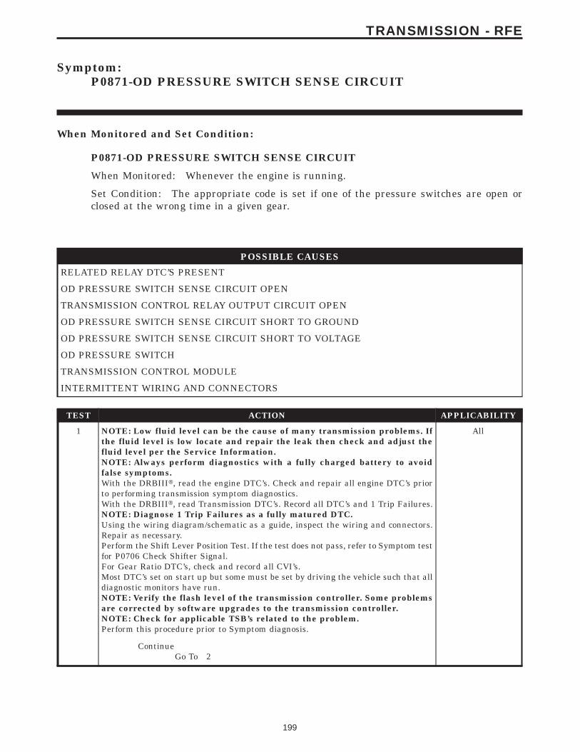
Symptom:P0871-OD PRESSURE SWITCH SENSE CIRCUIT
When Monitored and Set Condition:
P0871-OD PRESSURE SWITCH SENSE CIRCUIT
When Monitored: Whenever the engine is running.
Set Condition: The appropriate code is set if one of the pressure switches are open orclosed at the wrong time in a given gear.
POSSIBLE CAUSES
RELATED RELAY DTC’S PRESENT
OD PRESSURE SWITCH SENSE CIRCUIT OPEN
TRANSMISSION CONTROL RELAY OUTPUT CIRCUIT OPEN
OD PRESSURE SWITCH SENSE CIRCUIT SHORT TO GROUND
OD PRESSURE SWITCH SENSE CIRCUIT SHORT TO VOLTAGE
OD PRESSURE SWITCH
TRANSMISSION CONTROL MODULE
INTERMITTENT WIRING AND CONNECTORS
TEST ACTION APPLICABILITY
1 NOTE: Low fluid level can be the cause of many transmission problems. Ifthe fluid level is low locate and repair the leak then check and adjust thefluid level per the Service Information.NOTE: Always perform diagnostics with a fully charged battery to avoidfalse symptoms.With the DRBIIIt, read the engine DTC’s. Check and repair all engine DTC’s priorto performing transmission symptom diagnostics.With the DRBIIIt, read Transmission DTC’s. Record all DTC’s and 1 Trip Failures.NOTE: Diagnose 1 Trip Failures as a fully matured DTC.Using the wiring diagram/schematic as a guide, inspect the wiring and connectors.Repair as necessary.Perform the Shift Lever Position Test. If the test does not pass, refer to Symptom testfor P0706 Check Shifter Signal.For Gear Ratio DTC’s, check and record all CVI’s.Most DTC’s set on start up but some must be set by driving the vehicle such that alldiagnostic monitors have run.NOTE: Verify the flash level of the transmission controller. Some problemsare corrected by software upgrades to the transmission controller.NOTE: Check for applicable TSB’s related to the problem.Perform this procedure prior to Symptom diagnosis.
All
ContinueGo To 2
199
TRANSMISSION - RFE
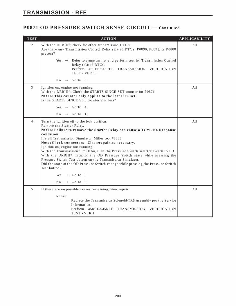
TEST ACTION APPLICABILITY
2 With the DRBIIIt, check for other transmission DTC’s.Are there any Transmission Control Relay related DTC’s, P0890, P0891, or P0888present?
All
Yes → Refer to symptom list and perform test for Transmission ControlRelay related DTCs.Perform 45RFE/545RFE TRANSMISSION VERIFICATIONTEST - VER 1.
No → Go To 3
3 Ignition on, engine not running.With the DRBIIIt, Check the STARTS SINCE SET counter for P0871.NOTE: This counter only applies to the last DTC set.Is the STARTS SINCE SET counter 2 or less?
All
Yes → Go To 4
No → Go To 11
4 Turn the ignition off to the lock position.Remove the Starter Relay.NOTE: Failure to remove the Starter Relay can cause a TCM - No Responsecondition.Install Transmission Simulator, Miller tool #8333.Note: Check connectors - Clean/repair as necessary.Ignition on, engine not running.With the Transmission Simulator, turn the Pressure Switch selector switch to OD.With the DRBIIIt, monitor the OD Pressure Switch state while pressing thePressure Switch Test button on the Transmission Simulator.Did the state of the OD Pressure Switch change while pressing the Pressure SwitchTest button?
All
Yes → Go To 5
No → Go To 6
5 If there are no possible causes remaining, view repair. All
RepairReplace the Transmission Solenoid/TRS Assembly per the ServiceInformation.Perform 45RFE/545RFE TRANSMISSION VERIFICATIONTEST - VER 1.
200
TRANSMISSION - RFE
P0871-OD PRESSURE SWITCH SENSE CIRCUIT — Continued
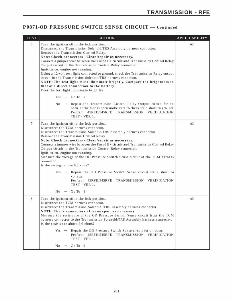
TEST ACTION APPLICABILITY
6 Turn the ignition off to the lock position.Disconnect the Transmission Solenoid/TRS Assembly harness connector.Remove the Transmission Control Relay.Note: Check connectors - Clean/repair as necessary.Connect a jumper wire between the Fused B+ circuit and Transmission Control RelayOutput circuit in the Transmission Control Relay connector.Ignition on, engine not running.Using a 12-volt test light connected to ground, check the Transmission Relay outputcircuit in the Transmission Solenoid/TRS harness connector.NOTE: The test light must illuminate brightly. Compare the brightness tothat of a direct connection to the battery.Does the test light illuminate brightly?
All
Yes → Go To 7
No → Repair the Transmission Control Relay Output circuit for anopen. If the fuse is open make sure to check for a short to ground.Perform 45RFE/545RFE TRANSMISSION VERIFICATIONTEST - VER 1.
7 Turn the ignition off to the lock position.Disconnect the TCM harness connector.Disconnect the Transmission Solenoid/TRS Assembly harness connector.Remove the Transmission Control Relay.Note: Check connectors - Clean/repair as necessary.Connect a jumper wire between the Fused B+ circuit and Transmission Control RelayOutput circuit in the Transmission Control Relay connector.Ignition on, engine not running.Measure the voltage of the OD Pressure Switch Sense circuit at the TCM harnessconnector.Is the voltage above 0.5 volts?
All
Yes → Repair the OD Pressure Switch Sense circuit for a short tovoltage.Perform 45RFE/545RFE TRANSMISSION VERIFICATIONTEST - VER 1.
No → Go To 8
8 Turn the ignition off to the lock position.Disconnect the TCM harness connector.Disconnect the Transmission Solenoid /TRS Assembly harness connectorNOTE: Check connectors - Clean/repair as necessary.Measure the resistance of the OD Pressure Switch Sense circuit from the TCMharness connector to the Transmission Solenoid/TRS Assembly harness connector.Is the resistance above 5.0 ohms?
All
Yes → Repair the OD Pressure Switch Sense circuit for an open.Perform 45RFE/545RFE TRANSMISSION VERIFICATIONTEST - VER 1.
No → Go To 9
201
TRANSMISSION - RFE
P0871-OD PRESSURE SWITCH SENSE CIRCUIT — Continued
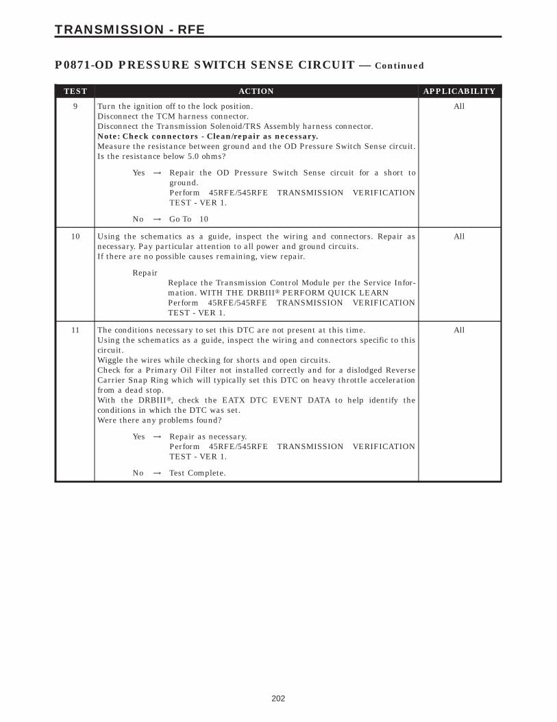
TEST ACTION APPLICABILITY
9 Turn the ignition off to the lock position.Disconnect the TCM harness connector.Disconnect the Transmission Solenoid/TRS Assembly harness connector.Note: Check connectors - Clean/repair as necessary.Measure the resistance between ground and the OD Pressure Switch Sense circuit.Is the resistance below 5.0 ohms?
All
Yes → Repair the OD Pressure Switch Sense circuit for a short toground.Perform 45RFE/545RFE TRANSMISSION VERIFICATIONTEST - VER 1.
No → Go To 10
10 Using the schematics as a guide, inspect the wiring and connectors. Repair asnecessary. Pay particular attention to all power and ground circuits.If there are no possible causes remaining, view repair.
All
RepairReplace the Transmission Control Module per the Service Infor-mation. WITH THE DRBIIIt PERFORM QUICK LEARNPerform 45RFE/545RFE TRANSMISSION VERIFICATIONTEST - VER 1.
11 The conditions necessary to set this DTC are not present at this time.Using the schematics as a guide, inspect the wiring and connectors specific to thiscircuit.Wiggle the wires while checking for shorts and open circuits.Check for a Primary Oil Filter not installed correctly and for a dislodged ReverseCarrier Snap Ring which will typically set this DTC on heavy throttle accelerationfrom a dead stop.With the DRBIIIt, check the EATX DTC EVENT DATA to help identify theconditions in which the DTC was set.Were there any problems found?
All
Yes → Repair as necessary.Perform 45RFE/545RFE TRANSMISSION VERIFICATIONTEST - VER 1.
No → Test Complete.
202
TRANSMISSION - RFE
P0871-OD PRESSURE SWITCH SENSE CIRCUIT — Continued
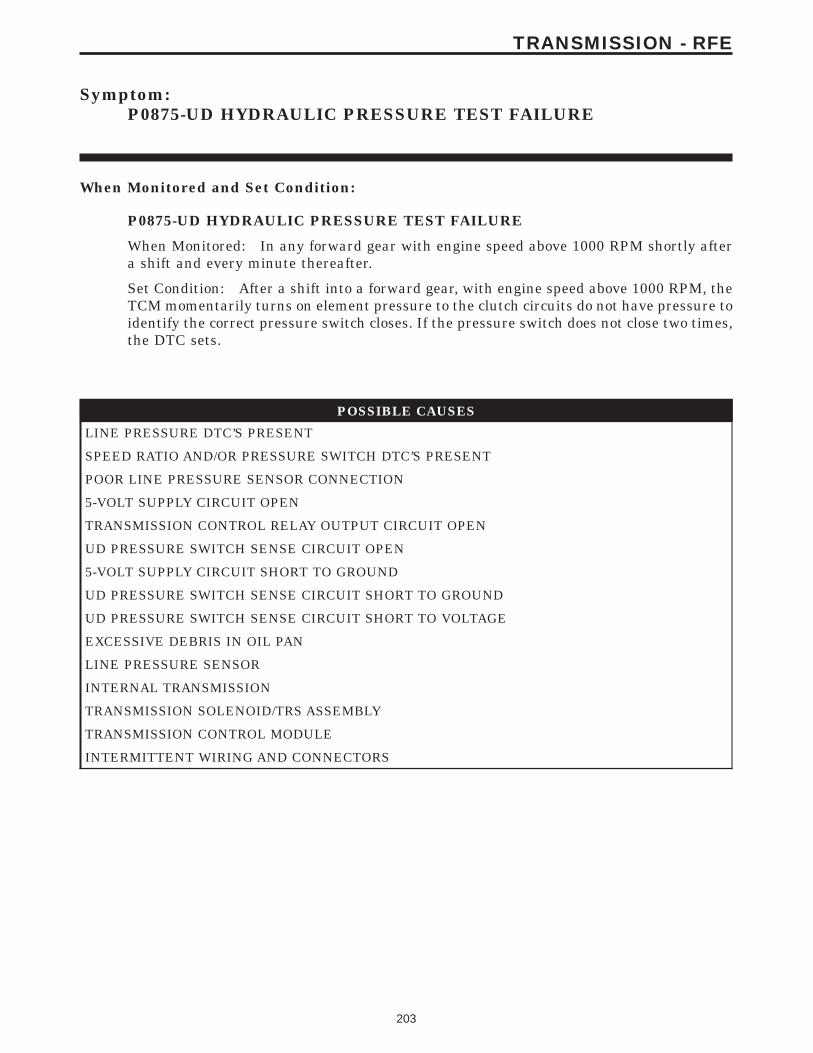
Symptom:P0875-UD HYDRAULIC PRESSURE TEST FAILURE
When Monitored and Set Condition:
P0875-UD HYDRAULIC PRESSURE TEST FAILURE
When Monitored: In any forward gear with engine speed above 1000 RPM shortly aftera shift and every minute thereafter.
Set Condition: After a shift into a forward gear, with engine speed above 1000 RPM, theTCM momentarily turns on element pressure to the clutch circuits do not have pressure toidentify the correct pressure switch closes. If the pressure switch does not close two times,the DTC sets.
POSSIBLE CAUSES
LINE PRESSURE DTC’S PRESENT
SPEED RATIO AND/OR PRESSURE SWITCH DTC’S PRESENT
POOR LINE PRESSURE SENSOR CONNECTION
5-VOLT SUPPLY CIRCUIT OPEN
TRANSMISSION CONTROL RELAY OUTPUT CIRCUIT OPEN
UD PRESSURE SWITCH SENSE CIRCUIT OPEN
5-VOLT SUPPLY CIRCUIT SHORT TO GROUND
UD PRESSURE SWITCH SENSE CIRCUIT SHORT TO GROUND
UD PRESSURE SWITCH SENSE CIRCUIT SHORT TO VOLTAGE
EXCESSIVE DEBRIS IN OIL PAN
LINE PRESSURE SENSOR
INTERNAL TRANSMISSION
TRANSMISSION SOLENOID/TRS ASSEMBLY
TRANSMISSION CONTROL MODULE
INTERMITTENT WIRING AND CONNECTORS
203
TRANSMISSION - RFE
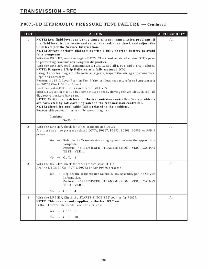
TEST ACTION APPLICABILITY
1 NOTE: Low fluid level can be the cause of many transmission problems. Ifthe fluid level is low locate and repair the leak then check and adjust thefluid level per the Service Information.NOTE: Always perform diagnostics with a fully charged battery to avoidfalse symptoms.With the DRBIIIt, read the engine DTC’s. Check and repair all engine DTC’s priorto performing transmission symptom diagnostics.With the DRBIIIt, read Transmission DTC’s. Record all DTC’s and 1 Trip Failures.NOTE: Diagnose 1 Trip Failures as a fully matured DTC.Using the wiring diagram/schematic as a guide, inspect the wiring and connectors.Repair as necessary.Perform the Shift Lever Position Test. If the test does not pass, refer to Symptom testfor P0706 Check Shifter Signal.For Gear Ratio DTC’s, check and record all CVI’s.Most DTC’s set on start up but some must be set by driving the vehicle such that alldiagnostic monitors have run.NOTE: Verify the flash level of the transmission controller. Some problemsare corrected by software upgrades to the transmission controller.NOTE: Check for applicable TSB’s related to the problem.Perform this procedure prior to Symptom diagnosis.
All
ContinueGo To 2
2 With the DRBIIIt, check for other Transmission DTC’sAre there any line pressure related DTC’s, P0867, P0932, P0868, P0869, or P0944present?
All
Yes → Refer to the Transmission category and perform the appropriatesymptom.Perform 45RFE/545RFE TRANSMISSION VERIFICATIONTEST - VER 1.
No → Go To 3
3 With the DRBIIIt, check for other transmission DTC’sAre the DTC’s P0731, P0732, P0733 and/or P0876 present?
All
Yes → Replace the Transmission Solenoid/TRS Assembly per the ServiceInformation.Perform 45RFE/545RFE TRANSMISSION VERIFICATIONTEST - VER 1.
No → Go To 4
4 With the DRBIIIt, Check the STARTS SINCE SET counter for P0875.NOTE: This counter only applies to the last DTC set.Is the STARTS SINCE SET counter 2 or less?
All
Yes → Go To 5
No → Go To 18
204
TRANSMISSION - RFE
P0875-UD HYDRAULIC PRESSURE TEST FAILURE — Continued
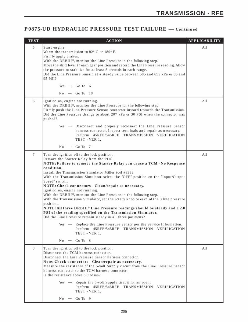
TEST ACTION APPLICABILITY
5 Start engine.Warm the transmission to 82° C or 180° F.Firmly apply brakes.With the DRBIIIt, monitor the Line Pressure in the following step.Move the shift lever to each gear position and record the Line Pressure reading. Allowthe pressure to stabilize for at least 5 seconds in each range.Did the Line Pressure remain at a steady value between 585 and 655 kPa or 85 and95 PSI?
All
Yes → Go To 6
No → Go To 10
6 Ignition on, engine not running.With the DRBIIIt, monitor the Line Pressure for the following step.Firmly push the Line Pressure Sensor connector inward towards the Transmission.Did the Line Pressure change to about 207 kPa or 30 PSI when the connector waspushed?
All
Yes → Disconnect and properly reconnect the Line Pressure Sensorharness connector. Inspect terminals and repair as necessary.Perform 45RFE/545RFE TRANSMISSION VERIFICATIONTEST - VER 1.
No → Go To 7
7 Turn the ignition off to the lock position.Remove the Starter Relay from the PDC.NOTE: Failure to remove the Starter Relay can cause a TCM - No Responsecondition.Install the Transmission Simulator Miller tool #8333.With the Transmission Simulator select the 9OFF9 position on the 9Input/OutputSpeed9 switch.NOTE: Check connectors - Clean/repair as necessary.Ignition on, engine not running.With the DRBIIIt, monitor the Line Pressure in the following step.With the Transmission Simulator, set the rotary knob to each of the 3 line pressurepositions.NOTE: All three DRBIIIt Line Pressure readings should be steady and ± 2.0PSI of the reading specified on the Transmission Simulator.Did the Line Pressure remain steady in all three positions?
All
Yes → Replace the Line Pressure Sensor per the Service Information.Perform 45RFE/545RFE TRANSMISSION VERIFICATIONTEST - VER 1.
No → Go To 8
8 Turn the ignition off to the lock position.Disconnect the TCM harness connector.Disconnect the Line Pressure Sensor harness connector.Note: Check connectors - Clean/repair as necessary.Measure the resistance of the 5-volt Supply circuit from the Line Pressure Sensorharness connector to the TCM harness connector.Is the resistance above 5.0 ohms?
All
Yes → Repair the 5-volt Supply circuit for an open.Perform 45RFE/545RFE TRANSMISSION VERIFICATIONTEST - VER 1.
No → Go To 9
205
TRANSMISSION - RFE
P0875-UD HYDRAULIC PRESSURE TEST FAILURE — Continued
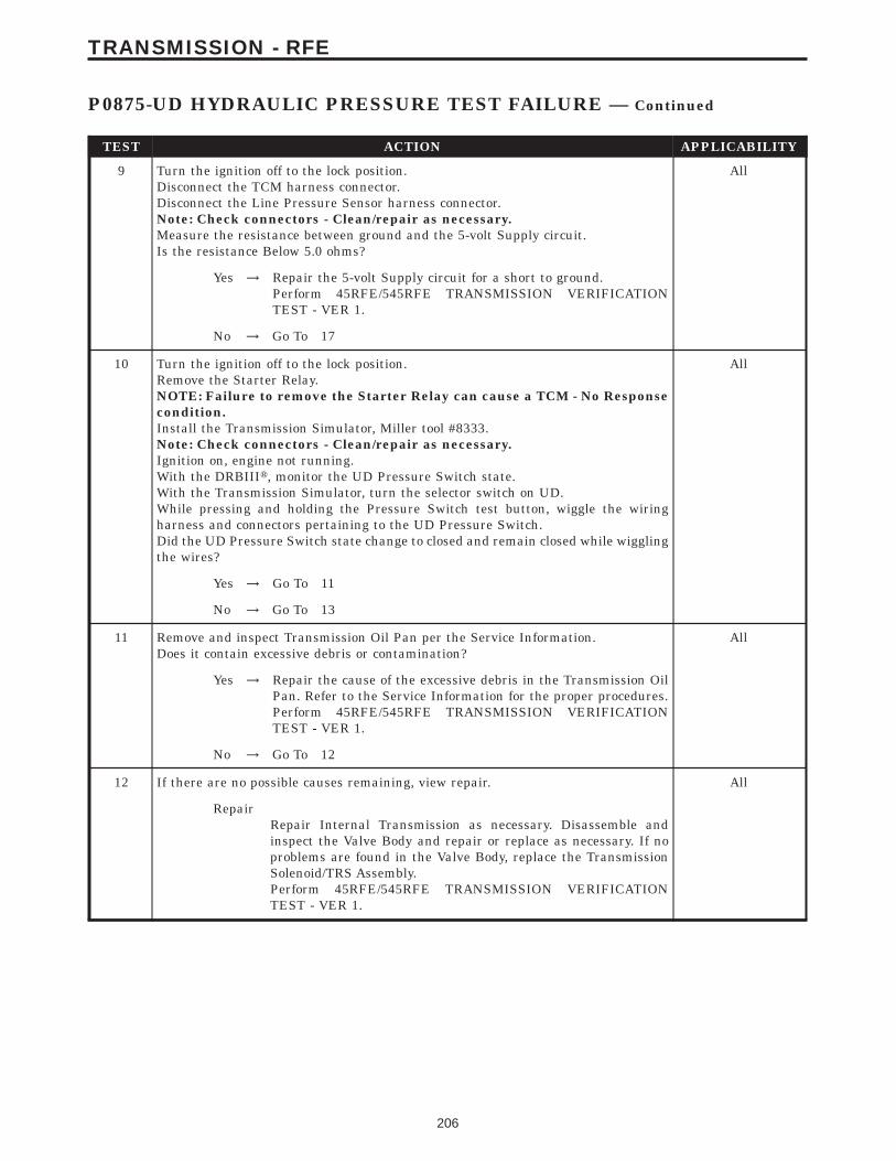
TEST ACTION APPLICABILITY
9 Turn the ignition off to the lock position.Disconnect the TCM harness connector.Disconnect the Line Pressure Sensor harness connector.Note: Check connectors - Clean/repair as necessary.Measure the resistance between ground and the 5-volt Supply circuit.Is the resistance Below 5.0 ohms?
All
Yes → Repair the 5-volt Supply circuit for a short to ground.Perform 45RFE/545RFE TRANSMISSION VERIFICATIONTEST - VER 1.
No → Go To 17
10 Turn the ignition off to the lock position.Remove the Starter Relay.NOTE: Failure to remove the Starter Relay can cause a TCM - No Responsecondition.Install the Transmission Simulator, Miller tool #8333.Note: Check connectors - Clean/repair as necessary.Ignition on, engine not running.With the DRBIIIt, monitor the UD Pressure Switch state.With the Transmission Simulator, turn the selector switch on UD.While pressing and holding the Pressure Switch test button, wiggle the wiringharness and connectors pertaining to the UD Pressure Switch.Did the UD Pressure Switch state change to closed and remain closed while wigglingthe wires?
All
Yes → Go To 11
No → Go To 13
11 Remove and inspect Transmission Oil Pan per the Service Information.Does it contain excessive debris or contamination?
All
Yes → Repair the cause of the excessive debris in the Transmission OilPan. Refer to the Service Information for the proper procedures.Perform 45RFE/545RFE TRANSMISSION VERIFICATIONTEST - VER 1.
No → Go To 12
12 If there are no possible causes remaining, view repair. All
RepairRepair Internal Transmission as necessary. Disassemble andinspect the Valve Body and repair or replace as necessary. If noproblems are found in the Valve Body, replace the TransmissionSolenoid/TRS Assembly.Perform 45RFE/545RFE TRANSMISSION VERIFICATIONTEST - VER 1.
206
TRANSMISSION - RFE
P0875-UD HYDRAULIC PRESSURE TEST FAILURE — Continued

TEST ACTION APPLICABILITY
13 Turn the ignition off to the lock position.Disconnect the TCM harness connector.Disconnect the Transmission Solenoid /TRS Assembly harness connector.Note: Check connectors - Clean/repair as necessary.Measure the resistance of the UD Pressure Switch Sense circuit from the TCMharness connector to the Solenoid/TRS Assembly harness connector.Is the resistance above 5.0 ohms?
All
Yes → Repair the UD Pressure Switch Sense circuit for an open.Perform 45RFE/545RFE TRANSMISSION VERIFICATIONTEST - VER 1.
No → Go To 14
14 Turn the ignition off to the lock position.Disconnect the TCM harness connector.Disconnect the Transmission Solenoid/TRS Assembly harness connector.Note: Check connectors - Clean/repair as necessary.Measure the resistance between ground and the UD Pressure Switch Sense circuit.Is the resistance below 5.0 ohms?
All
Yes → Repair the UD Pressure Switch Sense circuit for a short toground.Perform 45RFE/545RFE TRANSMISSION VERIFICATIONTEST - VER 1.
No → Go To 15
15 Turn the ignition off to the lock position.Disconnect the TCM harness connector.Disconnect the Transmission Solenoid/TRS Assembly harness connector.Remove the Transmission Control Relay.Note: Check connectors - Clean/repair as necessary.Connect a jumper wire between the Fused B+ circuit and the Transmission ControlRelay Output circuit in the Transmission Control Relay connector.Ignition on, engine not running.Measure the voltage of the UD Pressure Switch Sense circuit in the TCM harnessconnector.Is the voltage above 0.5 volt?
All
Yes → Repair the UD Pressure Switch Sense circuit for a short tovoltage.Perform 45RFE/545RFE TRANSMISSION VERIFICATIONTEST - VER 1.
No → Go To 16
207
TRANSMISSION - RFE
P0875-UD HYDRAULIC PRESSURE TEST FAILURE — Continued
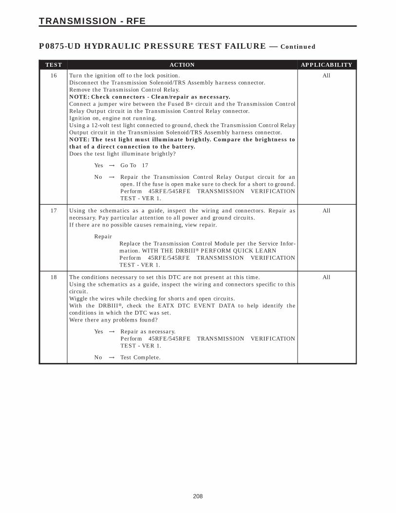
TEST ACTION APPLICABILITY
16 Turn the ignition off to the lock position.Disconnect the Transmission Solenoid/TRS Assembly harness connector.Remove the Transmission Control Relay.NOTE: Check connectors - Clean/repair as necessary.Connect a jumper wire between the Fused B+ circuit and the Transmission ControlRelay Output circuit in the Transmission Control Relay connector.Ignition on, engine not running.Using a 12-volt test light connected to ground, check the Transmission Control RelayOutput circuit in the Transmission Solenoid/TRS Assembly harness connector.NOTE: The test light must illuminate brightly. Compare the brightness tothat of a direct connection to the battery.Does the test light illuminate brightly?
All
Yes → Go To 17
No → Repair the Transmission Control Relay Output circuit for anopen. If the fuse is open make sure to check for a short to ground.Perform 45RFE/545RFE TRANSMISSION VERIFICATIONTEST - VER 1.
17 Using the schematics as a guide, inspect the wiring and connectors. Repair asnecessary. Pay particular attention to all power and ground circuits.If there are no possible causes remaining, view repair.
All
RepairReplace the Transmission Control Module per the Service Infor-mation. WITH THE DRBIIIt PERFORM QUICK LEARNPerform 45RFE/545RFE TRANSMISSION VERIFICATIONTEST - VER 1.
18 The conditions necessary to set this DTC are not present at this time.Using the schematics as a guide, inspect the wiring and connectors specific to thiscircuit.Wiggle the wires while checking for shorts and open circuits.With the DRBIIIt, check the EATX DTC EVENT DATA to help identify theconditions in which the DTC was set.Were there any problems found?
All
Yes → Repair as necessary.Perform 45RFE/545RFE TRANSMISSION VERIFICATIONTEST - VER 1.
No → Test Complete.
208
TRANSMISSION - RFE
P0875-UD HYDRAULIC PRESSURE TEST FAILURE — Continued

Symptom:P0876-UD PRESSURE SWITCH SENSE CIRCUIT
When Monitored and Set Condition:
P0876-UD PRESSURE SWITCH SENSE CIRCUIT
When Monitored: Whenever the engine is running.
Set Condition: This DTC is set if the UD pressure switch is in the wrong state for thecurrent gear. For example, this code would be set if the UD pressure switch remained offwhile the transmission was in second gear.
POSSIBLE CAUSES
RELAY DTC’S PRESENT
TRANSMISSION CONTROL RELAY OUTPUT CIRCUIT OPEN
UD PRESSURE SWITCH SENSE CIRCUIT OPEN
UD PRESSURE SWITCH CIRCUIT SHORT TO GROUND
UD PRESSURE SWITCH SENSE CIRCUIT SHORT TO VOLTAGE
UD PRESSURE SWITCH
TRANSMISSION CONTROL MODULE
INTERMITTENT WIRING AND CONNECTORS
TEST ACTION APPLICABILITY
1 NOTE: Low fluid level can be the cause of many transmission problems. Ifthe fluid level is low locate and repair the leak then check and adjust thefluid level per the Service Information.NOTE: Always perform diagnostics with a fully charged battery to avoidfalse symptoms.With the DRBIIIt, read the engine DTC’s. Check and repair all engine DTC’s priorto performing transmission symptom diagnostics.With the DRBIIIt, read Transmission DTC’s. Record all DTC’s and 1 Trip Failures.NOTE: Diagnose 1 Trip Failures as a fully matured DTC.Using the wiring diagram/schematic as a guide, inspect the wiring and connectors.Repair as necessary.Perform the Shift Lever Position Test. If the test does not pass, refer to Symptom testfor P0706 Check Shifter Signal.For Gear Ratio DTC’s, check and record all CVI’s.Most DTC’s set on start up but some must be set by driving the vehicle such that alldiagnostic monitors have run.NOTE: Verify the flash level of the transmission controller. Some problemsare corrected by software upgrades to the transmission controller.NOTE: Check for applicable TSB’s related to the problem.Perform this procedure prior to Symptom diagnosis.
All
ContinueGo To 2
209
TRANSMISSION - RFE
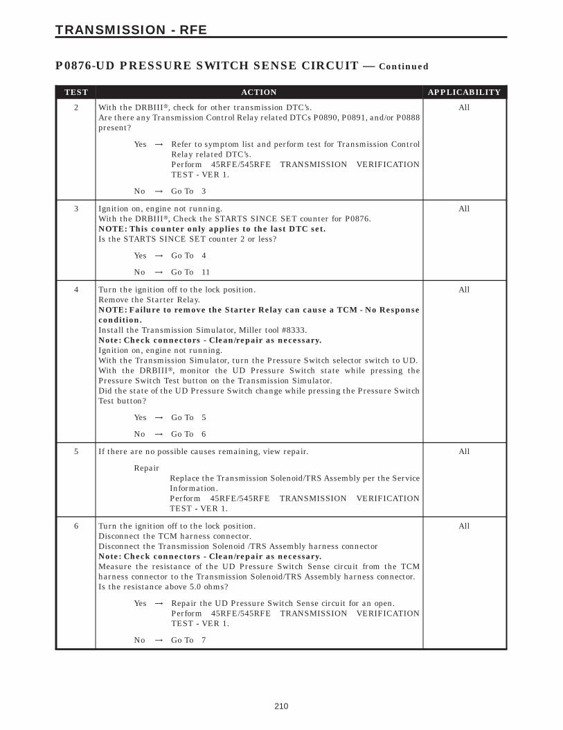
TEST ACTION APPLICABILITY
2 With the DRBIIIt, check for other transmission DTC’s.Are there any Transmission Control Relay related DTCs P0890, P0891, and/or P0888present?
All
Yes → Refer to symptom list and perform test for Transmission ControlRelay related DTC’s.Perform 45RFE/545RFE TRANSMISSION VERIFICATIONTEST - VER 1.
No → Go To 3
3 Ignition on, engine not running.With the DRBIIIt, Check the STARTS SINCE SET counter for P0876.NOTE: This counter only applies to the last DTC set.Is the STARTS SINCE SET counter 2 or less?
All
Yes → Go To 4
No → Go To 11
4 Turn the ignition off to the lock position.Remove the Starter Relay.NOTE: Failure to remove the Starter Relay can cause a TCM - No Responsecondition.Install the Transmission Simulator, Miller tool #8333.Note: Check connectors - Clean/repair as necessary.Ignition on, engine not running.With the Transmission Simulator, turn the Pressure Switch selector switch to UD.With the DRBIIIt, monitor the UD Pressure Switch state while pressing thePressure Switch Test button on the Transmission Simulator.Did the state of the UD Pressure Switch change while pressing the Pressure SwitchTest button?
All
Yes → Go To 5
No → Go To 6
5 If there are no possible causes remaining, view repair. All
RepairReplace the Transmission Solenoid/TRS Assembly per the ServiceInformation.Perform 45RFE/545RFE TRANSMISSION VERIFICATIONTEST - VER 1.
6 Turn the ignition off to the lock position.Disconnect the TCM harness connector.Disconnect the Transmission Solenoid /TRS Assembly harness connectorNote: Check connectors - Clean/repair as necessary.Measure the resistance of the UD Pressure Switch Sense circuit from the TCMharness connector to the Transmission Solenoid/TRS Assembly harness connector.Is the resistance above 5.0 ohms?
All
Yes → Repair the UD Pressure Switch Sense circuit for an open.Perform 45RFE/545RFE TRANSMISSION VERIFICATIONTEST - VER 1.
No → Go To 7
210
TRANSMISSION - RFE
P0876-UD PRESSURE SWITCH SENSE CIRCUIT — Continued

TEST ACTION APPLICABILITY
7 Turn the ignition off to the lock position.Disconnect the TCM harness connector.Disconnect the Transmission Solenoid/TRS Assembly harness connector.Note: Check connectors - Clean/repair as necessary.Measure the resistance between ground and the UD Pressure Switch Sense circuit.Is the resistance below 5.0 ohms?
All
Yes → Repair the UD Pressure Switch Sense circuit for a short toground.Perform 45RFE/545RFE TRANSMISSION VERIFICATIONTEST - VER 1.
No → Go To 8
8 Turn the ignition off to the lock position.Disconnect the TCM harness connector.Disconnect the Transmission Solenoid/TRS Assembly harness connector.Remove the Transmission Control Relay.Note: Check connectors - Clean/repair as necessary.Connect a jumper wire between the Fused B+ circuit and the Transmission ControlRelay Output circuit in the Transmission Control Relay connector.Ignition on, engine not running.Measure the voltage of the UD Pressure Switch Sense circuit.Is the voltage above 0.5 volt?
All
Yes → Repair the UD Pressure Switch Sense circuit for a short tovoltage.Perform 45RFE/545RFE TRANSMISSION VERIFICATIONTEST - VER 1.
No → Go To 9
9 Turn the ignition off to the lock position.Disconnect the Transmission Solenoid/TRS Assembly harness connector.Remove the Transmission Control Relay.Note: Check connectors - Clean/repair as necessary.Connect a jumper wire between Transmission Control Relay circuit and Fused B(+).Ignition on, engine not running.Using a 12-volt test light connected to ground, check the Transmission Control RelayOutput circuit in the Solenoid/TRS Assembly harness connector.NOTE: The test light must illuminate brightly. Compare the brightness tothat of a direct connection to the battery.Does the test light illuminate brightly?
All
Yes → Go To 10
No → Repair the Transmission Control Relay Output circuit for anopen. If the fuse is open make sure to check for a short to ground.Perform 45RFE/545RFE TRANSMISSION VERIFICATIONTEST - VER 1.
10 Using the schematics as a guide, inspect the wiring and connectors. Repair asnecessary. Pay particular attention to all power and ground circuits.If there are no possible causes remaining, view repair.
All
Repair.Replace the Transmission Control Module per the Service Infor-mation. WITH THE DRBIIIt PERFORM QUICK LEARNPerform 45RFE/545RFE TRANSMISSION VERIFICATIONTEST - VER 1.
211
TRANSMISSION - RFE
P0876-UD PRESSURE SWITCH SENSE CIRCUIT — Continued
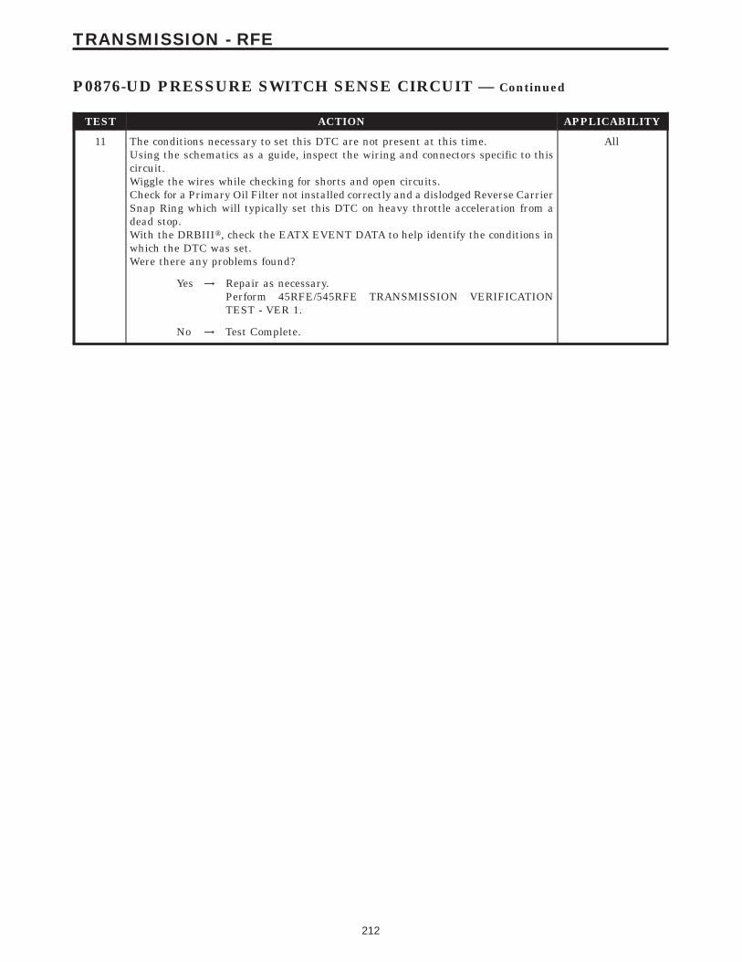
TEST ACTION APPLICABILITY
11 The conditions necessary to set this DTC are not present at this time.Using the schematics as a guide, inspect the wiring and connectors specific to thiscircuit.Wiggle the wires while checking for shorts and open circuits.Check for a Primary Oil Filter not installed correctly and a dislodged Reverse CarrierSnap Ring which will typically set this DTC on heavy throttle acceleration from adead stop.With the DRBIIIt, check the EATX EVENT DATA to help identify the conditions inwhich the DTC was set.Were there any problems found?
All
Yes → Repair as necessary.Perform 45RFE/545RFE TRANSMISSION VERIFICATIONTEST - VER 1.
No → Test Complete.
212
TRANSMISSION - RFE
P0876-UD PRESSURE SWITCH SENSE CIRCUIT — Continued
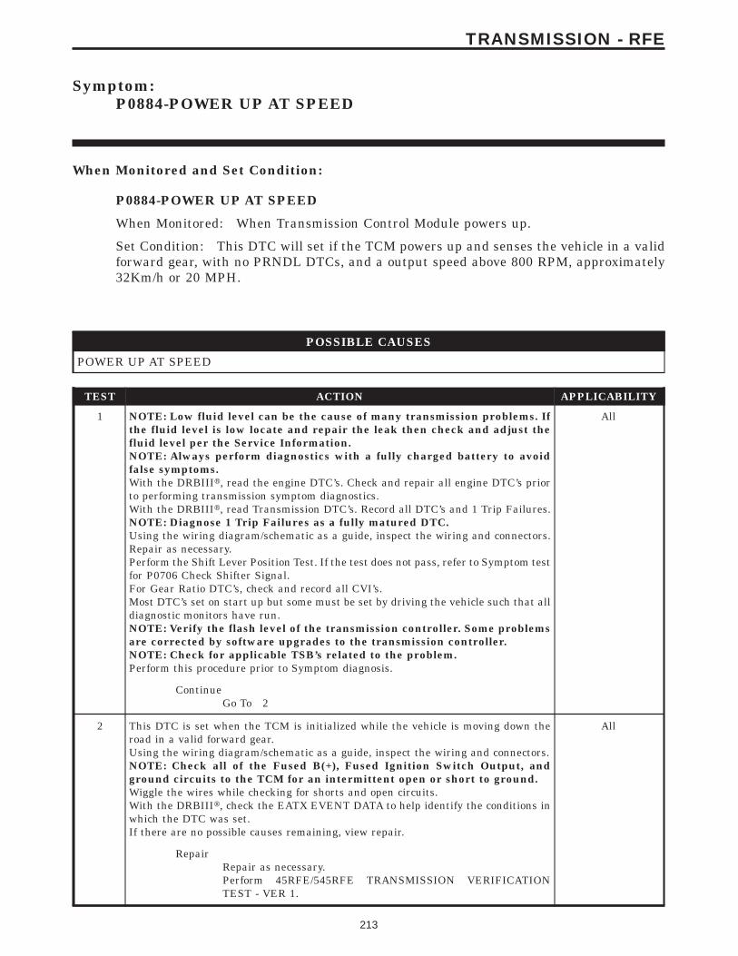
Symptom:P0884-POWER UP AT SPEED
When Monitored and Set Condition:
P0884-POWER UP AT SPEED
When Monitored: When Transmission Control Module powers up.
Set Condition: This DTC will set if the TCM powers up and senses the vehicle in a validforward gear, with no PRNDL DTCs, and a output speed above 800 RPM, approximately32Km/h or 20 MPH.
POSSIBLE CAUSES
POWER UP AT SPEED
TEST ACTION APPLICABILITY
1 NOTE: Low fluid level can be the cause of many transmission problems. Ifthe fluid level is low locate and repair the leak then check and adjust thefluid level per the Service Information.NOTE: Always perform diagnostics with a fully charged battery to avoidfalse symptoms.With the DRBIIIt, read the engine DTC’s. Check and repair all engine DTC’s priorto performing transmission symptom diagnostics.With the DRBIIIt, read Transmission DTC’s. Record all DTC’s and 1 Trip Failures.NOTE: Diagnose 1 Trip Failures as a fully matured DTC.Using the wiring diagram/schematic as a guide, inspect the wiring and connectors.Repair as necessary.Perform the Shift Lever Position Test. If the test does not pass, refer to Symptom testfor P0706 Check Shifter Signal.For Gear Ratio DTC’s, check and record all CVI’s.Most DTC’s set on start up but some must be set by driving the vehicle such that alldiagnostic monitors have run.NOTE: Verify the flash level of the transmission controller. Some problemsare corrected by software upgrades to the transmission controller.NOTE: Check for applicable TSB’s related to the problem.Perform this procedure prior to Symptom diagnosis.
All
ContinueGo To 2
2 This DTC is set when the TCM is initialized while the vehicle is moving down theroad in a valid forward gear.Using the wiring diagram/schematic as a guide, inspect the wiring and connectors.NOTE: Check all of the Fused B(+), Fused Ignition Switch Output, andground circuits to the TCM for an intermittent open or short to ground.Wiggle the wires while checking for shorts and open circuits.With the DRBIIIt, check the EATX EVENT DATA to help identify the conditions inwhich the DTC was set.If there are no possible causes remaining, view repair.
All
RepairRepair as necessary.Perform 45RFE/545RFE TRANSMISSION VERIFICATIONTEST - VER 1.
213
TRANSMISSION - RFE
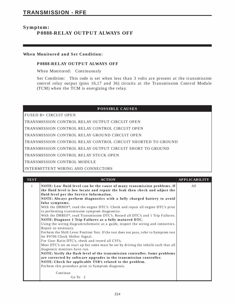
Symptom:P0888-RELAY OUTPUT ALWAYS OFF
When Monitored and Set Condition:
P0888-RELAY OUTPUT ALWAYS OFF
When Monitored: Continuously
Set Condition: This code is set when less than 3 volts are present at the transmissioncontrol relay output (pins 16,17 and 36) circuits at the Transmission Control Module(TCM) when the TCM is energizing the relay.
POSSIBLE CAUSES
FUSED B+ CIRCUIT OPEN
TRANSMISSION CONTROL RELAY OUTPUT CIRCUIT OPEN
TRANSMISSION CONTROL RELAY CONTROL CIRCUIT OPEN
TRANSMISSION CONTROL RELAY GROUND CIRCUIT OPEN
TRANSMISSION CONTROL RELAY CONTROL CIRCUIT SHORTED TO GROUND
TRANSMISSION CONTROL RELAY OUTPUT CIRCUIT SHORT TO GROUND
TRANSMISSION CONTROL RELAY STUCK OPEN
TRANSMISSION CONTROL MODULE
INTERMITTENT WIRING AND CONNECTORS
TEST ACTION APPLICABILITY
1 NOTE: Low fluid level can be the cause of many transmission problems. Ifthe fluid level is low locate and repair the leak then check and adjust thefluid level per the Service Information.NOTE: Always perform diagnostics with a fully charged battery to avoidfalse symptoms.With the DRBIIIt, read the engine DTC’s. Check and repair all engine DTC’s priorto performing transmission symptom diagnostics.With the DRBIIIt, read Transmission DTC’s. Record all DTC’s and 1 Trip Failures.NOTE: Diagnose 1 Trip Failures as a fully matured DTC.Using the wiring diagram/schematic as a guide, inspect the wiring and connectors.Repair as necessary.Perform the Shift Lever Position Test. If the test does not pass, refer to Symptom testfor P0706 Check Shifter Signal.For Gear Ratio DTC’s, check and record all CVI’s.Most DTC’s set on start up but some must be set by driving the vehicle such that alldiagnostic monitors have run.NOTE: Verify the flash level of the transmission controller. Some problemsare corrected by software upgrades to the transmission controller.NOTE: Check for applicable TSB’s related to the problem.Perform this procedure prior to Symptom diagnosis.
All
ContinueGo To 2
214
TRANSMISSION - RFE
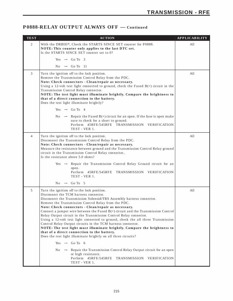
TEST ACTION APPLICABILITY
2 With the DRBIIIt, Check the STARTS SINCE SET counter for P0888.NOTE: This counter only applies to the last DTC set.Is the STARTS SINCE SET counter set to 0?
All
Yes → Go To 3
No → Go To 11
3 Turn the ignition off to the lock position.Remove the Transmission Control Relay from the PDC.Note: Check connectors - Clean/repair as necessary.Using a 12-volt test light connected to ground, check the Fused B(+) circuit in theTransmission Control Relay connector.NOTE: The test light must illuminate brightly. Compare the brightness tothat of a direct connection to the battery.Does the test light illuminate brightly?
All
Yes → Go To 4
No → Repair the Fused B(+) circuit for an open. If the fuse is open makesure to check for a short to ground.Perform 45RFE/545RFE TRANSMISSION VERIFICATIONTEST - VER 1.
4 Turn the ignition off to the lock position.Disconnect the Transmission Control Relay from the PDC.Note: Check connectors - Clean/repair as necessary.Measure the resistance between ground and the Transmission Control Relay groundcircuit in the Transmission Control Relay connector..Is the resistance above 5.0 ohms?
All
Yes → Repair the Transmission Control Relay Ground circuit for anopen.Perform 45RFE/545RFE TRANSMISSION VERIFICATIONTEST - VER 1.
No → Go To 5
5 Turn the ignition off to the lock position.Disconnect the TCM harness connector.Disconnect the Transmission Solenoid/TRS Assembly harness connector.Remove the Transmission Control Relay from the PDC.Note: Check connectors - Clean/repair as necessary.Connect a jumper wire between the Fused B(+) circuit and the Transmission ControlRelay Output circuit in the Transmission Control Relay connector.Using a 12-volt test light connected to ground, check the all three TransmissionControl Relay Output circuits in the TCM harness connector.NOTE: The test light must illuminate brightly. Compare the brightness tothat of a direct connection to the battery.Does the test light illuminate brightly on all three circuits?
All
Yes → Go To 6
No → Repair the Transmission Control Relay Output circuit for an openor high resistance.Perform 45RFE/545RFE TRANSMISSION VERIFICATIONTEST - VER 1.
215
TRANSMISSION - RFE
P0888-RELAY OUTPUT ALWAYS OFF — Continued
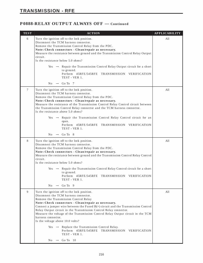
TEST ACTION APPLICABILITY
6 Turn the ignition off to the lock position.Disconnect the TCM harness connector.Remove the Transmission Control Relay from the PDC.Note: Check connectors - Clean/repair as necessary.Measure the resistance between ground and the Transmission Control Relay Outputcircuit.Is the resistance below 5.0 ohms?
All
Yes → Repair the Transmission Control Relay Output circuit for a shortto ground.Perform 45RFE/545RFE TRANSMISSION VERIFICATIONTEST - VER 1.
No → Go To 7
7 Turn the ignition off to the lock position.Disconnect the TCM harness connector.Remove the Transmission Control Relay from the PDC.Note: Check connectors - Clean/repair as necessary.Measure the resistance of the Transmission Control Relay Control circuit betweenthe Transmission Control Relay connector and the TCM harness connector.Is the resistance above 5.0 ohms?
All
Yes → Repair the Transmission Control Relay Control circuit for anopen.Perform 45RFE/545RFE TRANSMISSION VERIFICATIONTEST - VER 1.
No → Go To 8
8 Turn the ignition off to the lock position.Disconnect the TCM harness connector.Remove the Transmission Control Relay from the PDC.Note: Check connectors - Clean/repair as necessary.Measure the resistance between ground and the Transmission Control Relay Controlcircuit.Is the resistance below 5.0 ohms?
All
Yes → Repair the Transmission Control Relay Control circuit for a shortto ground.Perform 45RFE/545RFE TRANSMISSION VERIFICATIONTEST - VER 1.
No → Go To 9
9 Turn the ignition off to the lock position.Disconnect the TCM harness connector.Remove the Transmission Control RelayNote: Check connectors - Clean/repair as necessary.Connect a jumper wire between the Fused B(+) circuit and the Transmission ControlRelay Output circuit in the Transmission Control Relay connector.Measure the voltage of the Transmission Control Relay Output circuit in the TCMharness connector.Is the voltage above 10.0 volts?
All
Yes → Replace the Transmission Control Relay.Perform 45RFE/545RFE TRANSMISSION VERIFICATIONTEST - VER 1.
No → Go To 10
216
TRANSMISSION - RFE
P0888-RELAY OUTPUT ALWAYS OFF — Continued

TEST ACTION APPLICABILITY
10 Using the schematics as a guide, inspect the wiring and connectors. Repair asnecessary. Pay particular attention to all power and ground circuits.If there are no possible causes remaining, view repair.
All
RepairReplace the Transmission Control Module per the Service Infor-mation. WITH THE DRBIIIt PERFORM QUICK LEARNPerform 45RFE/545RFE TRANSMISSION VERIFICATIONTEST - VER 1.
11 The conditions necessary to set this DTC are not present at this time.Using the schematics as a guide, inspect the wiring and connectors specific to thiscircuit.Wiggle the wires while checking for shorts and open circuits.With the DRBIIIt, check the EATX DTC EVENT DATA to help identify theconditions in which the DTC was set.Were there any problems found?
All
Yes → Repair as necessary.Perform 45RFE/545RFE TRANSMISSION VERIFICATIONTEST - VER 1.
No → Test Complete.
217
TRANSMISSION - RFE
P0888-RELAY OUTPUT ALWAYS OFF — Continued
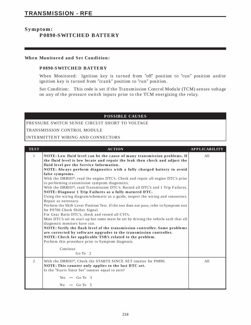
Symptom:P0890-SWITCHED BATTERY
When Monitored and Set Condition:
P0890-SWITCHED BATTERY
When Monitored: Ignition key is turned from 9off9 position to 9run9 position and/orignition key is turned from 9crank9 position to 9run9 position.
Set Condition: This code is set if the Transmission Control Module (TCM) senses voltageon any of the pressure switch inputs prior to the TCM energizing the relay.
POSSIBLE CAUSES
PRESSURE SWITCH SENSE CIRCUIT SHORT TO VOLTAGE
TRANSMISSION CONTROL MODULE
INTERMITTENT WIRING AND CONNECTORS
TEST ACTION APPLICABILITY
1 NOTE: Low fluid level can be the cause of many transmission problems. Ifthe fluid level is low locate and repair the leak then check and adjust thefluid level per the Service Information.NOTE: Always perform diagnostics with a fully charged battery to avoidfalse symptoms.With the DRBIIIt, read the engine DTC’s. Check and repair all engine DTC’s priorto performing transmission symptom diagnostics.With the DRBIIIt, read Transmission DTC’s. Record all DTC’s and 1 Trip Failures.NOTE: Diagnose 1 Trip Failures as a fully matured DTC.Using the wiring diagram/schematic as a guide, inspect the wiring and connectors.Repair as necessary.Perform the Shift Lever Position Test. If the test does not pass, refer to Symptom testfor P0706 Check Shifter Signal.For Gear Ratio DTC’s, check and record all CVI’s.Most DTC’s set on start up but some must be set by driving the vehicle such that alldiagnostic monitors have run.NOTE: Verify the flash level of the transmission controller. Some problemsare corrected by software upgrades to the transmission controller.NOTE: Check for applicable TSB’s related to the problem.Perform this procedure prior to Symptom diagnosis.
All
ContinueGo To 2
2 With the DRBIIIt, Check the STARTS SINCE SET counter for P0890.NOTE: This counter only applies to the last DTC set.Is the 9Starts Since Set9 counter equal to zero?
All
Yes → Go To 3
No → Go To 5
218
TRANSMISSION - RFE
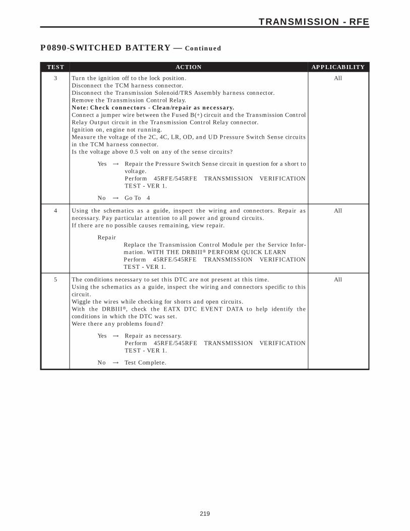
TEST ACTION APPLICABILITY
3 Turn the ignition off to the lock position.Disconnect the TCM harness connector.Disconnect the Transmission Solenoid/TRS Assembly harness connector.Remove the Transmission Control Relay.Note: Check connectors - Clean/repair as necessary.Connect a jumper wire between the Fused B(+) circuit and the Transmission ControlRelay Output circuit in the Transmission Control Relay connector.Ignition on, engine not running.Measure the voltage of the 2C, 4C, LR, OD, and UD Pressure Switch Sense circuitsin the TCM harness connector.Is the voltage above 0.5 volt on any of the sense circuits?
All
Yes → Repair the Pressure Switch Sense circuit in question for a short tovoltage.Perform 45RFE/545RFE TRANSMISSION VERIFICATIONTEST - VER 1.
No → Go To 4
4 Using the schematics as a guide, inspect the wiring and connectors. Repair asnecessary. Pay particular attention to all power and ground circuits.If there are no possible causes remaining, view repair.
All
RepairReplace the Transmission Control Module per the Service Infor-mation. WITH THE DRBIIIt PERFORM QUICK LEARNPerform 45RFE/545RFE TRANSMISSION VERIFICATIONTEST - VER 1.
5 The conditions necessary to set this DTC are not present at this time.Using the schematics as a guide, inspect the wiring and connectors specific to thiscircuit.Wiggle the wires while checking for shorts and open circuits.With the DRBIIIt, check the EATX DTC EVENT DATA to help identify theconditions in which the DTC was set.Were there any problems found?
All
Yes → Repair as necessary.Perform 45RFE/545RFE TRANSMISSION VERIFICATIONTEST - VER 1.
No → Test Complete.
219
TRANSMISSION - RFE
P0890-SWITCHED BATTERY — Continued
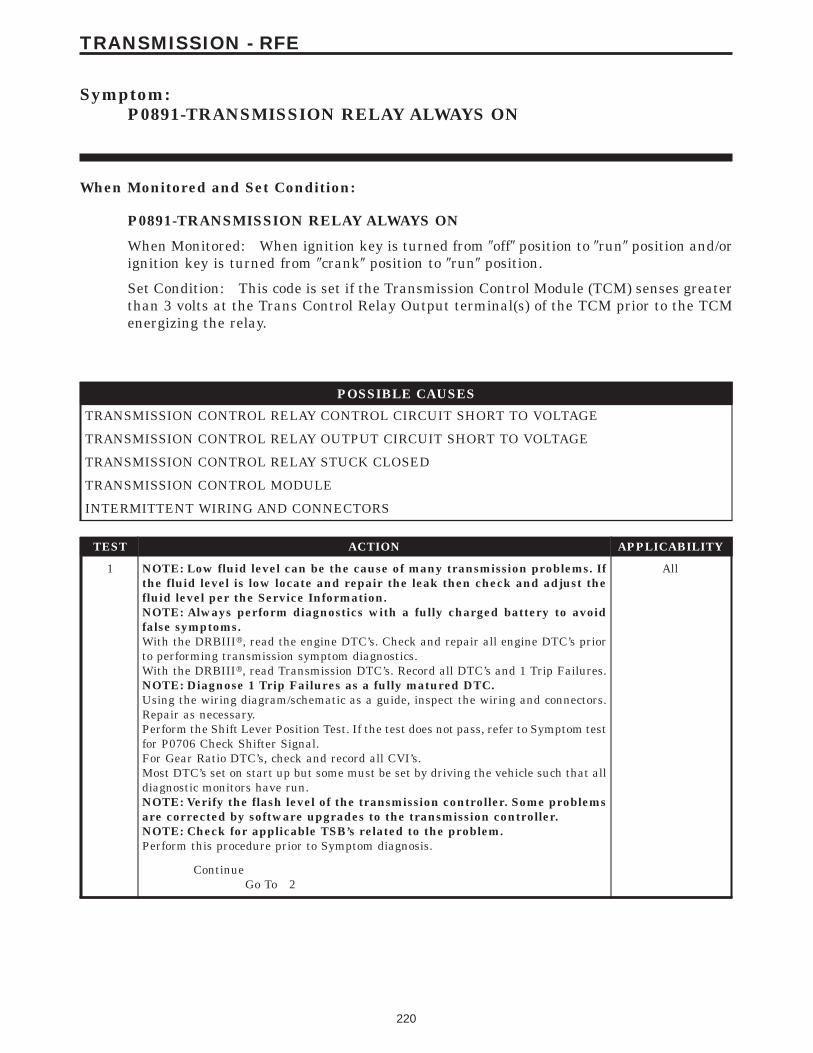
Symptom:P0891-TRANSMISSION RELAY ALWAYS ON
When Monitored and Set Condition:
P0891-TRANSMISSION RELAY ALWAYS ON
When Monitored: When ignition key is turned from 9off9 position to 9run9 position and/orignition key is turned from 9crank9 position to 9run9 position.
Set Condition: This code is set if the Transmission Control Module (TCM) senses greaterthan 3 volts at the Trans Control Relay Output terminal(s) of the TCM prior to the TCMenergizing the relay.
POSSIBLE CAUSES
TRANSMISSION CONTROL RELAY CONTROL CIRCUIT SHORT TO VOLTAGE
TRANSMISSION CONTROL RELAY OUTPUT CIRCUIT SHORT TO VOLTAGE
TRANSMISSION CONTROL RELAY STUCK CLOSED
TRANSMISSION CONTROL MODULE
INTERMITTENT WIRING AND CONNECTORS
TEST ACTION APPLICABILITY
1 NOTE: Low fluid level can be the cause of many transmission problems. Ifthe fluid level is low locate and repair the leak then check and adjust thefluid level per the Service Information.NOTE: Always perform diagnostics with a fully charged battery to avoidfalse symptoms.With the DRBIIIt, read the engine DTC’s. Check and repair all engine DTC’s priorto performing transmission symptom diagnostics.With the DRBIIIt, read Transmission DTC’s. Record all DTC’s and 1 Trip Failures.NOTE: Diagnose 1 Trip Failures as a fully matured DTC.Using the wiring diagram/schematic as a guide, inspect the wiring and connectors.Repair as necessary.Perform the Shift Lever Position Test. If the test does not pass, refer to Symptom testfor P0706 Check Shifter Signal.For Gear Ratio DTC’s, check and record all CVI’s.Most DTC’s set on start up but some must be set by driving the vehicle such that alldiagnostic monitors have run.NOTE: Verify the flash level of the transmission controller. Some problemsare corrected by software upgrades to the transmission controller.NOTE: Check for applicable TSB’s related to the problem.Perform this procedure prior to Symptom diagnosis.
All
ContinueGo To 2
220
TRANSMISSION - RFE
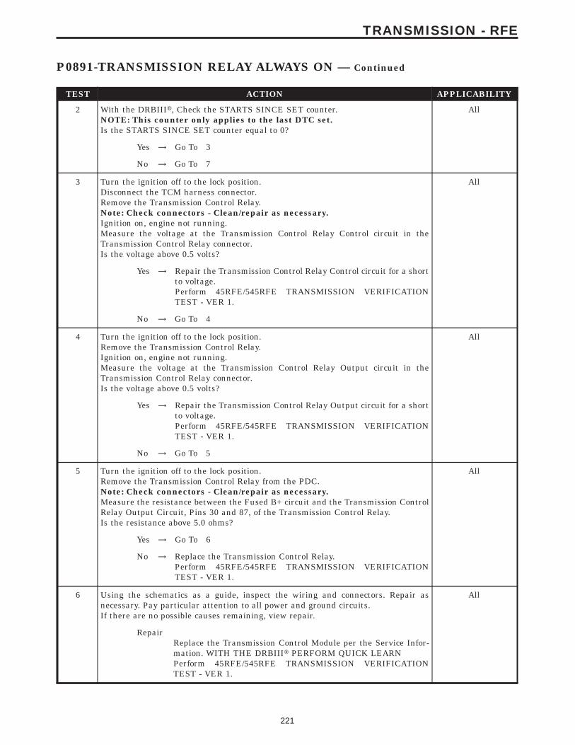
TEST ACTION APPLICABILITY
2 With the DRBIIIt, Check the STARTS SINCE SET counter.NOTE: This counter only applies to the last DTC set.Is the STARTS SINCE SET counter equal to 0?
All
Yes → Go To 3
No → Go To 7
3 Turn the ignition off to the lock position.Disconnect the TCM harness connector.Remove the Transmission Control Relay.Note: Check connectors - Clean/repair as necessary.Ignition on, engine not running.Measure the voltage at the Transmission Control Relay Control circuit in theTransmission Control Relay connector.Is the voltage above 0.5 volts?
All
Yes → Repair the Transmission Control Relay Control circuit for a shortto voltage.Perform 45RFE/545RFE TRANSMISSION VERIFICATIONTEST - VER 1.
No → Go To 4
4 Turn the ignition off to the lock position.Remove the Transmission Control Relay.Ignition on, engine not running.Measure the voltage at the Transmission Control Relay Output circuit in theTransmission Control Relay connector.Is the voltage above 0.5 volts?
All
Yes → Repair the Transmission Control Relay Output circuit for a shortto voltage.Perform 45RFE/545RFE TRANSMISSION VERIFICATIONTEST - VER 1.
No → Go To 5
5 Turn the ignition off to the lock position.Remove the Transmission Control Relay from the PDC.Note: Check connectors - Clean/repair as necessary.Measure the resistance between the Fused B+ circuit and the Transmission ControlRelay Output Circuit, Pins 30 and 87, of the Transmission Control Relay.Is the resistance above 5.0 ohms?
All
Yes → Go To 6
No → Replace the Transmission Control Relay.Perform 45RFE/545RFE TRANSMISSION VERIFICATIONTEST - VER 1.
6 Using the schematics as a guide, inspect the wiring and connectors. Repair asnecessary. Pay particular attention to all power and ground circuits.If there are no possible causes remaining, view repair.
All
RepairReplace the Transmission Control Module per the Service Infor-mation. WITH THE DRBIIIt PERFORM QUICK LEARNPerform 45RFE/545RFE TRANSMISSION VERIFICATIONTEST - VER 1.
221
TRANSMISSION - RFE
P0891-TRANSMISSION RELAY ALWAYS ON — Continued

TEST ACTION APPLICABILITY
7 The conditions necessary to set this DTC are not present at this time.Using the schematics as a guide, inspect the wiring and connectors specific to thiscircuit.Wiggle the wires while checking for shorts and open circuits.With the DRBIIIt, check the EATX DTC EVENT DATA to help identify theconditions in which the DTC was set.Were there any problems found?
All
Yes → Repair as necessary.Perform 45RFE/545RFE TRANSMISSION VERIFICATIONTEST - VER 1.
No → Test Complete.
222
TRANSMISSION - RFE
P0891-TRANSMISSION RELAY ALWAYS ON — Continued
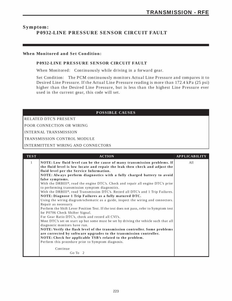
Symptom:P0932-LINE PRESSURE SENSOR CIRCUIT FAULT
When Monitored and Set Condition:
P0932-LINE PRESSURE SENSOR CIRCUIT FAULT
When Monitored: Continuously while driving in a forward gear.
Set Condition: The PCM continuously monitors Actual Line Pressure and compares it toDesired Line Pressure. If the Actual Line Pressure reading is more than 172.4 kPa (25 psi)higher than the Desired Line Pressure, but is less than the highest Line Pressure everused in the current gear, this code will set.
POSSIBLE CAUSES
RELATED DTC’S PRESENT
POOR CONNECTION OR WIRING
INTERNAL TRANSMISSION
TRANSMISSION CONTROL MODULE
INTERMITTENT WIRING AND CONNECTORS
TEST ACTION APPLICABILITY
1 NOTE: Low fluid level can be the cause of many transmission problems. Ifthe fluid level is low locate and repair the leak then check and adjust thefluid level per the Service Information.NOTE: Always perform diagnostics with a fully charged battery to avoidfalse symptoms.With the DRBIIIt, read the engine DTC’s. Check and repair all engine DTC’s priorto performing transmission symptom diagnostics.With the DRBIIIt, read Transmission DTC’s. Record all DTC’s and 1 Trip Failures.NOTE: Diagnose 1 Trip Failures as a fully matured DTC.Using the wiring diagram/schematic as a guide, inspect the wiring and connectors.Repair as necessary.Perform the Shift Lever Position Test. If the test does not pass, refer to Symptom testfor P0706 Check Shifter Signal.For Gear Ratio DTC’s, check and record all CVI’s.Most DTC’s set on start up but some must be set by driving the vehicle such that alldiagnostic monitors have run.NOTE: Verify the flash level of the transmission controller. Some problemsare corrected by software upgrades to the transmission controller.NOTE: Check for applicable TSB’s related to the problem.Perform this procedure prior to Symptom diagnosis.
All
ContinueGo To 2
223
TRANSMISSION - RFE
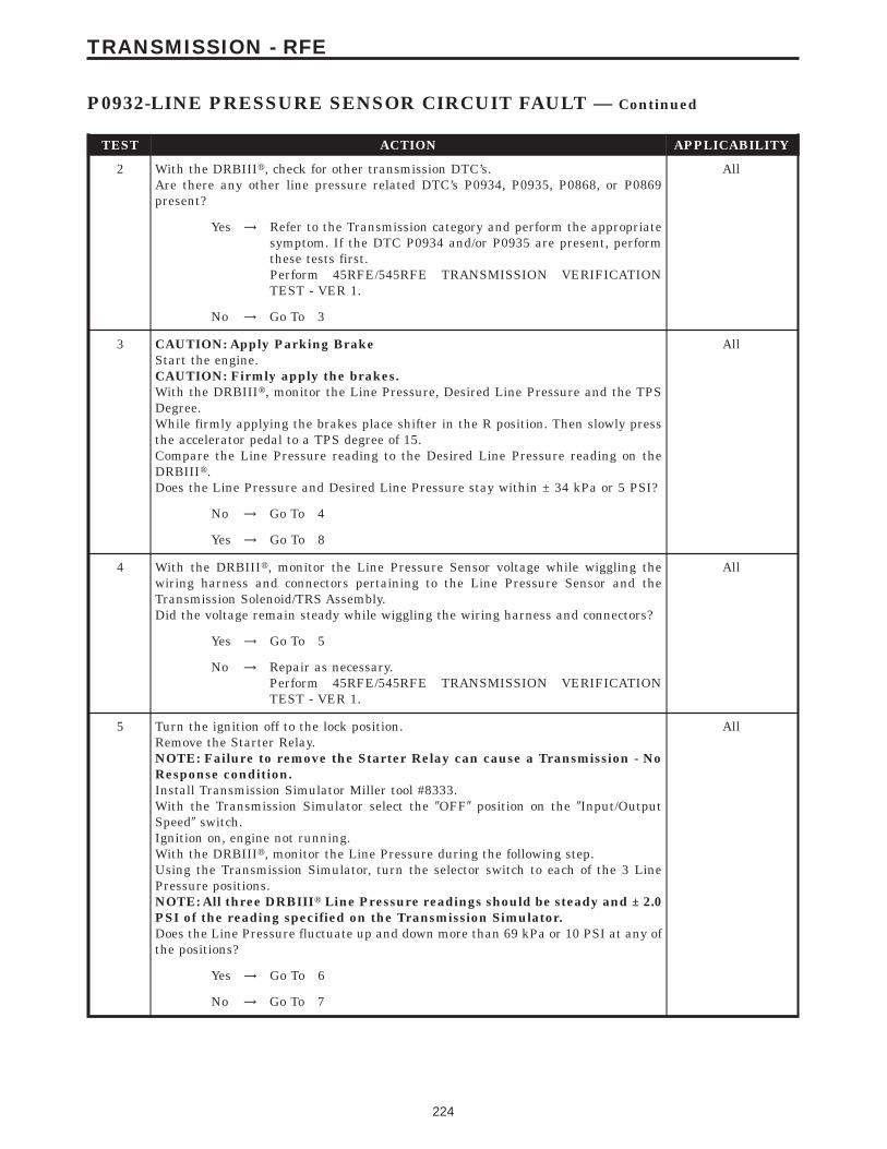
TEST ACTION APPLICABILITY
2 With the DRBIIIt, check for other transmission DTC’s.Are there any other line pressure related DTC’s P0934, P0935, P0868, or P0869present?
All
Yes → Refer to the Transmission category and perform the appropriatesymptom. If the DTC P0934 and/or P0935 are present, performthese tests first.Perform 45RFE/545RFE TRANSMISSION VERIFICATIONTEST - VER 1.
No → Go To 3
3 CAUTION: Apply Parking BrakeStart the engine.CAUTION: Firmly apply the brakes.With the DRBIIIt, monitor the Line Pressure, Desired Line Pressure and the TPSDegree.While firmly applying the brakes place shifter in the R position. Then slowly pressthe accelerator pedal to a TPS degree of 15.Compare the Line Pressure reading to the Desired Line Pressure reading on theDRBIIIt.Does the Line Pressure and Desired Line Pressure stay within ± 34 kPa or 5 PSI?
All
No → Go To 4
Yes → Go To 8
4 With the DRBIIIt, monitor the Line Pressure Sensor voltage while wiggling thewiring harness and connectors pertaining to the Line Pressure Sensor and theTransmission Solenoid/TRS Assembly.Did the voltage remain steady while wiggling the wiring harness and connectors?
All
Yes → Go To 5
No → Repair as necessary.Perform 45RFE/545RFE TRANSMISSION VERIFICATIONTEST - VER 1.
5 Turn the ignition off to the lock position.Remove the Starter Relay.NOTE: Failure to remove the Starter Relay can cause a Transmission - NoResponse condition.Install Transmission Simulator Miller tool #8333.With the Transmission Simulator select the 9OFF9 position on the 9Input/OutputSpeed9 switch.Ignition on, engine not running.With the DRBIIIt, monitor the Line Pressure during the following step.Using the Transmission Simulator, turn the selector switch to each of the 3 LinePressure positions.NOTE: All three DRBIIIt Line Pressure readings should be steady and ± 2.0PSI of the reading specified on the Transmission Simulator.Does the Line Pressure fluctuate up and down more than 69 kPa or 10 PSI at any ofthe positions?
All
Yes → Go To 6
No → Go To 7
224
TRANSMISSION - RFE
P0932-LINE PRESSURE SENSOR CIRCUIT FAULT — Continued
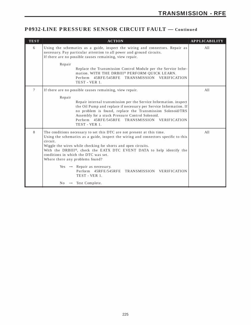
TEST ACTION APPLICABILITY
6 Using the schematics as a guide, inspect the wiring and connectors. Repair asnecessary. Pay particular attention to all power and ground circuits.If there are no possible causes remaining, view repair.
All
RepairReplace the Transmission Control Module per the Service Infor-mation. WITH THE DRBIIIt PERFORM QUICK LEARN.Perform 45RFE/545RFE TRANSMISSION VERIFICATIONTEST - VER 1.
7 If there are no possible causes remaining, view repair. All
RepairRepair internal transmission per the Service Information. inspectthe Oil Pump and replace if necessary per Service Information. Ifno problem is found, replace the Transmission Solenoid/TRSAssembly for a stuck Pressure Control Solenoid.Perform 45RFE/545RFE TRANSMISSION VERIFICATIONTEST - VER 1.
8 The conditions necessary to set this DTC are not present at this time.Using the schematics as a guide, inspect the wiring and connectors specific to thiscircuit.Wiggle the wires while checking for shorts and open circuits.With the DRBIIIt, check the EATX DTC EVENT DATA to help identify theconditions in which the DTC was set.Where there any problems found?
All
Yes → Repair as necessary.Perform 45RFE/545RFE TRANSMISSION VERIFICATIONTEST - VER 1.
No → Test Complete.
225
TRANSMISSION - RFE
P0932-LINE PRESSURE SENSOR CIRCUIT FAULT — Continued
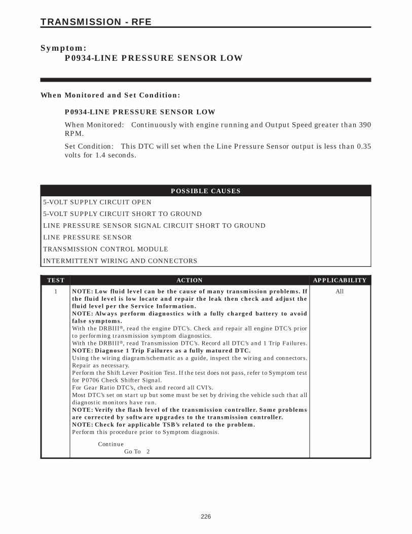
Symptom:P0934-LINE PRESSURE SENSOR LOW
When Monitored and Set Condition:
P0934-LINE PRESSURE SENSOR LOW
When Monitored: Continuously with engine running and Output Speed greater than 390RPM.
Set Condition: This DTC will set when the Line Pressure Sensor output is less than 0.35volts for 1.4 seconds.
POSSIBLE CAUSES
5-VOLT SUPPLY CIRCUIT OPEN
5-VOLT SUPPLY CIRCUIT SHORT TO GROUND
LINE PRESSURE SENSOR SIGNAL CIRCUIT SHORT TO GROUND
LINE PRESSURE SENSOR
TRANSMISSION CONTROL MODULE
INTERMITTENT WIRING AND CONNECTORS
TEST ACTION APPLICABILITY
1 NOTE: Low fluid level can be the cause of many transmission problems. Ifthe fluid level is low locate and repair the leak then check and adjust thefluid level per the Service Information.NOTE: Always perform diagnostics with a fully charged battery to avoidfalse symptoms.With the DRBIIIt, read the engine DTC’s. Check and repair all engine DTC’s priorto performing transmission symptom diagnostics.With the DRBIIIt, read Transmission DTC’s. Record all DTC’s and 1 Trip Failures.NOTE: Diagnose 1 Trip Failures as a fully matured DTC.Using the wiring diagram/schematic as a guide, inspect the wiring and connectors.Repair as necessary.Perform the Shift Lever Position Test. If the test does not pass, refer to Symptom testfor P0706 Check Shifter Signal.For Gear Ratio DTC’s, check and record all CVI’s.Most DTC’s set on start up but some must be set by driving the vehicle such that alldiagnostic monitors have run.NOTE: Verify the flash level of the transmission controller. Some problemsare corrected by software upgrades to the transmission controller.NOTE: Check for applicable TSB’s related to the problem.Perform this procedure prior to Symptom diagnosis.
All
ContinueGo To 2
226
TRANSMISSION - RFE
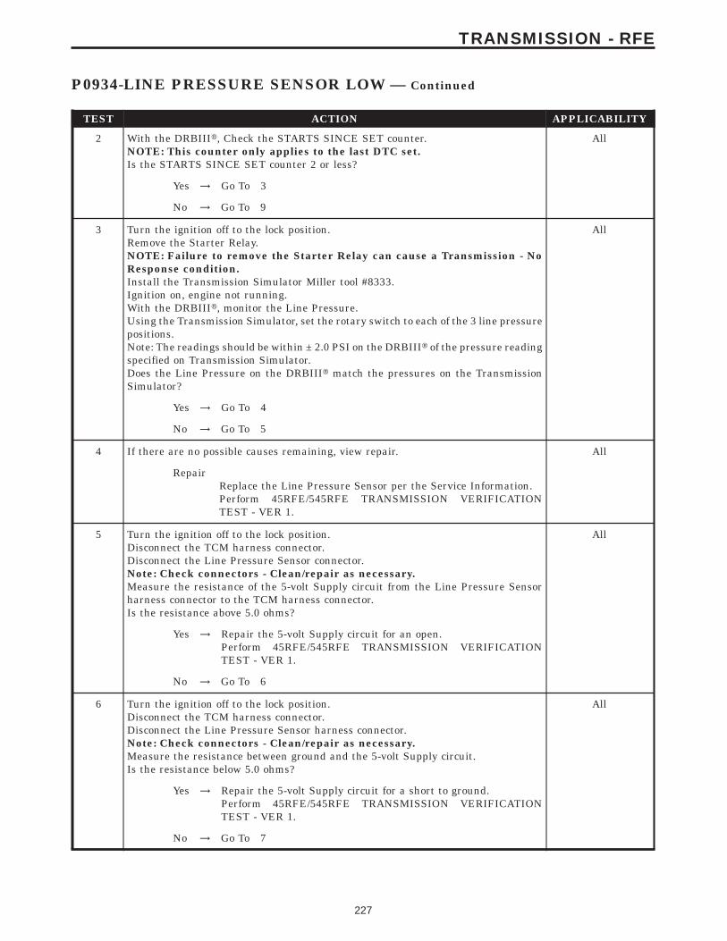
TEST ACTION APPLICABILITY
2 With the DRBIIIt, Check the STARTS SINCE SET counter.NOTE: This counter only applies to the last DTC set.Is the STARTS SINCE SET counter 2 or less?
All
Yes → Go To 3
No → Go To 9
3 Turn the ignition off to the lock position.Remove the Starter Relay.NOTE: Failure to remove the Starter Relay can cause a Transmission - NoResponse condition.Install the Transmission Simulator Miller tool #8333.Ignition on, engine not running.With the DRBIIIt, monitor the Line Pressure.Using the Transmission Simulator, set the rotary switch to each of the 3 line pressurepositions.Note: The readings should be within ± 2.0 PSI on the DRBIIIt of the pressure readingspecified on Transmission Simulator.Does the Line Pressure on the DRBIIIt match the pressures on the TransmissionSimulator?
All
Yes → Go To 4
No → Go To 5
4 If there are no possible causes remaining, view repair. All
RepairReplace the Line Pressure Sensor per the Service Information.Perform 45RFE/545RFE TRANSMISSION VERIFICATIONTEST - VER 1.
5 Turn the ignition off to the lock position.Disconnect the TCM harness connector.Disconnect the Line Pressure Sensor connector.Note: Check connectors - Clean/repair as necessary.Measure the resistance of the 5-volt Supply circuit from the Line Pressure Sensorharness connector to the TCM harness connector.Is the resistance above 5.0 ohms?
All
Yes → Repair the 5-volt Supply circuit for an open.Perform 45RFE/545RFE TRANSMISSION VERIFICATIONTEST - VER 1.
No → Go To 6
6 Turn the ignition off to the lock position.Disconnect the TCM harness connector.Disconnect the Line Pressure Sensor harness connector.Note: Check connectors - Clean/repair as necessary.Measure the resistance between ground and the 5-volt Supply circuit.Is the resistance below 5.0 ohms?
All
Yes → Repair the 5-volt Supply circuit for a short to ground.Perform 45RFE/545RFE TRANSMISSION VERIFICATIONTEST - VER 1.
No → Go To 7
227
TRANSMISSION - RFE
P0934-LINE PRESSURE SENSOR LOW — Continued
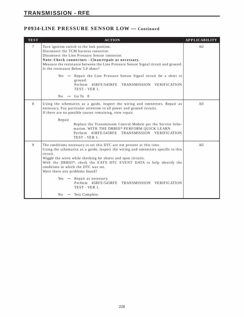
TEST ACTION APPLICABILITY
7 Turn ignition switch to the lock position.Disconnect the TCM harness connector.Disconnect the Line Pressure Sensor connector.Note: Check connectors - Clean/repair as necessary.Measure the resistance between the Line Pressure Sensor Signal circuit and ground.Is the resistance Below 5.0 ohms?
All
Yes → Repair the Line Pressure Sensor Signal circuit for a short toground.Perform 45RFE/545RFE TRANSMISSION VERIFICATIONTEST - VER 1.
No → Go To 8
8 Using the schematics as a guide, inspect the wiring and connectors. Repair asnecessary. Pay particular attention to all power and ground circuits.If there are no possible causes remaining, view repair.
All
RepairReplace the Transmission Control Module per the Service Infor-mation. WITH THE DRBIIIt PERFORM QUICK LEARNPerform 45RFE/545RFE TRANSMISSION VERIFICATIONTEST - VER 1.
9 The conditions necessary to set this DTC are not present at this time.Using the schematics as a guide, inspect the wiring and connectors specific to thiscircuit.Wiggle the wires while checking for shorts and open circuits.With the DRBIIIt, check the EATX DTC EVENT DATA to help identify theconditions in which the DTC was set.Were there any problems found?
All
Yes → Repair as necessary.Perform 45RFE/545RFE TRANSMISSION VERIFICATIONTEST - VER 1.
No → Test Complete.
228
TRANSMISSION - RFE
P0934-LINE PRESSURE SENSOR LOW — Continued
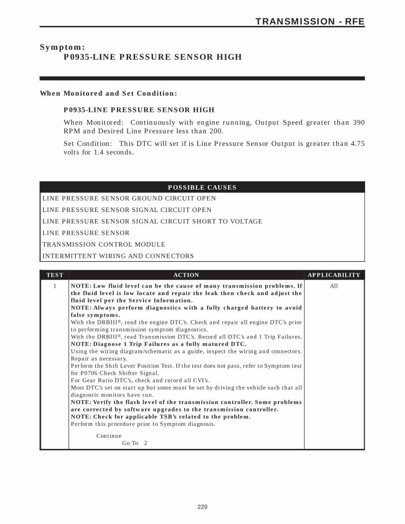
Symptom:P0935-LINE PRESSURE SENSOR HIGH
When Monitored and Set Condition:
P0935-LINE PRESSURE SENSOR HIGH
When Monitored: Continuously with engine running, Output Speed greater than 390RPM and Desired Line Pressure less than 200.
Set Condition: This DTC will set if is Line Pressure Sensor Output is greater than 4.75volts for 1.4 seconds.
POSSIBLE CAUSES
LINE PRESSURE SENSOR GROUND CIRCUIT OPEN
LINE PRESSURE SENSOR SIGNAL CIRCUIT OPEN
LINE PRESSURE SENSOR SIGNAL CIRCUIT SHORT TO VOLTAGE
LINE PRESSURE SENSOR
TRANSMISSION CONTROL MODULE
INTERMITTENT WIRING AND CONNECTORS
TEST ACTION APPLICABILITY
1 NOTE: Low fluid level can be the cause of many transmission problems. Ifthe fluid level is low locate and repair the leak then check and adjust thefluid level per the Service Information.NOTE: Always perform diagnostics with a fully charged battery to avoidfalse symptoms.With the DRBIIIt, read the engine DTC’s. Check and repair all engine DTC’s priorto performing transmission symptom diagnostics.With the DRBIIIt, read Transmission DTC’s. Record all DTC’s and 1 Trip Failures.NOTE: Diagnose 1 Trip Failures as a fully matured DTC.Using the wiring diagram/schematic as a guide, inspect the wiring and connectors.Repair as necessary.Perform the Shift Lever Position Test. If the test does not pass, refer to Symptom testfor P0706 Check Shifter Signal.For Gear Ratio DTC’s, check and record all CVI’s.Most DTC’s set on start up but some must be set by driving the vehicle such that alldiagnostic monitors have run.NOTE: Verify the flash level of the transmission controller. Some problemsare corrected by software upgrades to the transmission controller.NOTE: Check for applicable TSB’s related to the problem.Perform this procedure prior to Symptom diagnosis.
All
ContinueGo To 2
229
TRANSMISSION - RFE
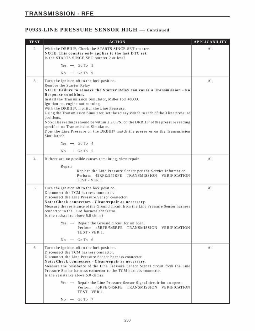
TEST ACTION APPLICABILITY
2 With the DRBIIIt, Check the STARTS SINCE SET counter.NOTE: This counter only applies to the last DTC set.Is the STARTS SINCE SET counter 2 or less?
All
Yes → Go To 3
No → Go To 9
3 Turn the ignition off to the lock position.Remove the Starter Relay.NOTE: Failure to remove the Starter Relay can cause a Transmission - NoResponse condition.Install the Transmission Simulator, Miller tool #8333.Ignition on, engine not running.With the DRBIIIt, monitor the Line Pressure.Using the Transmission Simulator, set the rotary switch to each of the 3 line pressurepositions.Note: The readings should be within ± 2.0 PSI on the DRBIIIt of the pressure readingspecified on Transmission Simulator.Does the Line Pressure on the DRBIIIt match the pressures on the TransmissionSimulator?
All
Yes → Go To 4
No → Go To 5
4 If there are no possible causes remaining, view repair. All
RepairReplace the Line Pressure Sensor per the Service Information.Perform 45RFE/545RFE TRANSMISSION VERIFICATIONTEST - VER 1.
5 Turn the ignition off to the lock position.Disconnect the TCM harness connector.Disconnect the Line Pressure Sensor connector.Note: Check connectors - Clean/repair as necessary.Measure the resistance of the Ground circuit from the Line Pressure Sensor harnessconnector to the TCM harness connector.Is the resistance above 5.0 ohms?
All
Yes → Repair the Ground circuit for an open.Perform 45RFE/545RFE TRANSMISSION VERIFICATIONTEST - VER 1.
No → Go To 6
6 Turn the ignition off to the lock position.Disconnect the TCM harness connector.Disconnect the Line Pressure Sensor harness connector.Note: Check connectors - Clean/repair as necessary.Measure the resistance of the Line Pressure Sensor Signal circuit from the LinePressure Sensor harness connector to the TCM harness connector.Is the resistance above 5.0 ohms?
All
Yes → Repair the Line Pressure Sensor Signal circuit for an open.Perform 45RFE/545RFE TRANSMISSION VERIFICATIONTEST - VER 1.
No → Go To 7
230
TRANSMISSION - RFE
P0935-LINE PRESSURE SENSOR HIGH — Continued
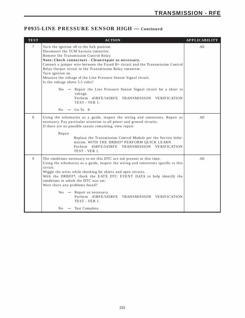
TEST ACTION APPLICABILITY
7 Turn the ignition off to the lock position.Disconnect the TCM harness connector.Remove the Transmission Control Relay.Note: Check connectors - Clean/repair as necessary.Connect a jumper wire between the Fused B+ circuit and the Transmission ControlRelay Output circuit in the Transmission Relay connector.Turn ignition on.Measure the voltage of the Line Pressure Sensor Signal circuit.Is the voltage above 5.5 volts?
All
Yes → Repair the Line Pressure Sensor Signal circuit for a short tovoltage.Perform 45RFE/545RFE TRANSMISSION VERIFICATIONTEST - VER 1.
No → Go To 8
8 Using the schematics as a guide, inspect the wiring and connectors. Repair asnecessary. Pay particular attention to all power and ground circuits.If there are no possible causes remaining, view repair.
All
RepairReplace the Transmission Control Module per the Service Infor-mation. WITH THE DRBIIIt PERFORM QUICK LEARNPerform 45RFE/545RFE TRANSMISSION VERIFICATIONTEST - VER 1.
9 The conditions necessary to set this DTC are not present at this time.Using the schematics as a guide, inspect the wiring and connectors specific to thiscircuit.Wiggle the wires while checking for shorts and open circuits.With the DRBIIIt, check the EATX DTC EVENT DATA to help identify theconditions in which the DTC was set.Were there any problems found?
All
Yes → Repair as necessary.Perform 45RFE/545RFE TRANSMISSION VERIFICATIONTEST - VER 1.
No → Test Complete.
231
TRANSMISSION - RFE
P0935-LINE PRESSURE SENSOR HIGH — Continued
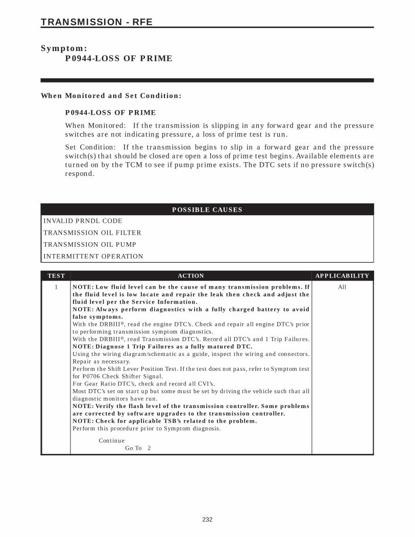
Symptom:P0944-LOSS OF PRIME
When Monitored and Set Condition:
P0944-LOSS OF PRIME
When Monitored: If the transmission is slipping in any forward gear and the pressureswitches are not indicating pressure, a loss of prime test is run.
Set Condition: If the transmission begins to slip in a forward gear and the pressureswitch(s) that should be closed are open a loss of prime test begins. Available elements areturned on by the TCM to see if pump prime exists. The DTC sets if no pressure switch(s)respond.
POSSIBLE CAUSES
INVALID PRNDL CODE
TRANSMISSION OIL FILTER
TRANSMISSION OIL PUMP
INTERMITTENT OPERATION
TEST ACTION APPLICABILITY
1 NOTE: Low fluid level can be the cause of many transmission problems. Ifthe fluid level is low locate and repair the leak then check and adjust thefluid level per the Service Information.NOTE: Always perform diagnostics with a fully charged battery to avoidfalse symptoms.With the DRBIIIt, read the engine DTC’s. Check and repair all engine DTC’s priorto performing transmission symptom diagnostics.With the DRBIIIt, read Transmission DTC’s. Record all DTC’s and 1 Trip Failures.NOTE: Diagnose 1 Trip Failures as a fully matured DTC.Using the wiring diagram/schematic as a guide, inspect the wiring and connectors.Repair as necessary.Perform the Shift Lever Position Test. If the test does not pass, refer to Symptom testfor P0706 Check Shifter Signal.For Gear Ratio DTC’s, check and record all CVI’s.Most DTC’s set on start up but some must be set by driving the vehicle such that alldiagnostic monitors have run.NOTE: Verify the flash level of the transmission controller. Some problemsare corrected by software upgrades to the transmission controller.NOTE: Check for applicable TSB’s related to the problem.Perform this procedure prior to Symptom diagnosis.
All
ContinueGo To 2
232
TRANSMISSION - RFE
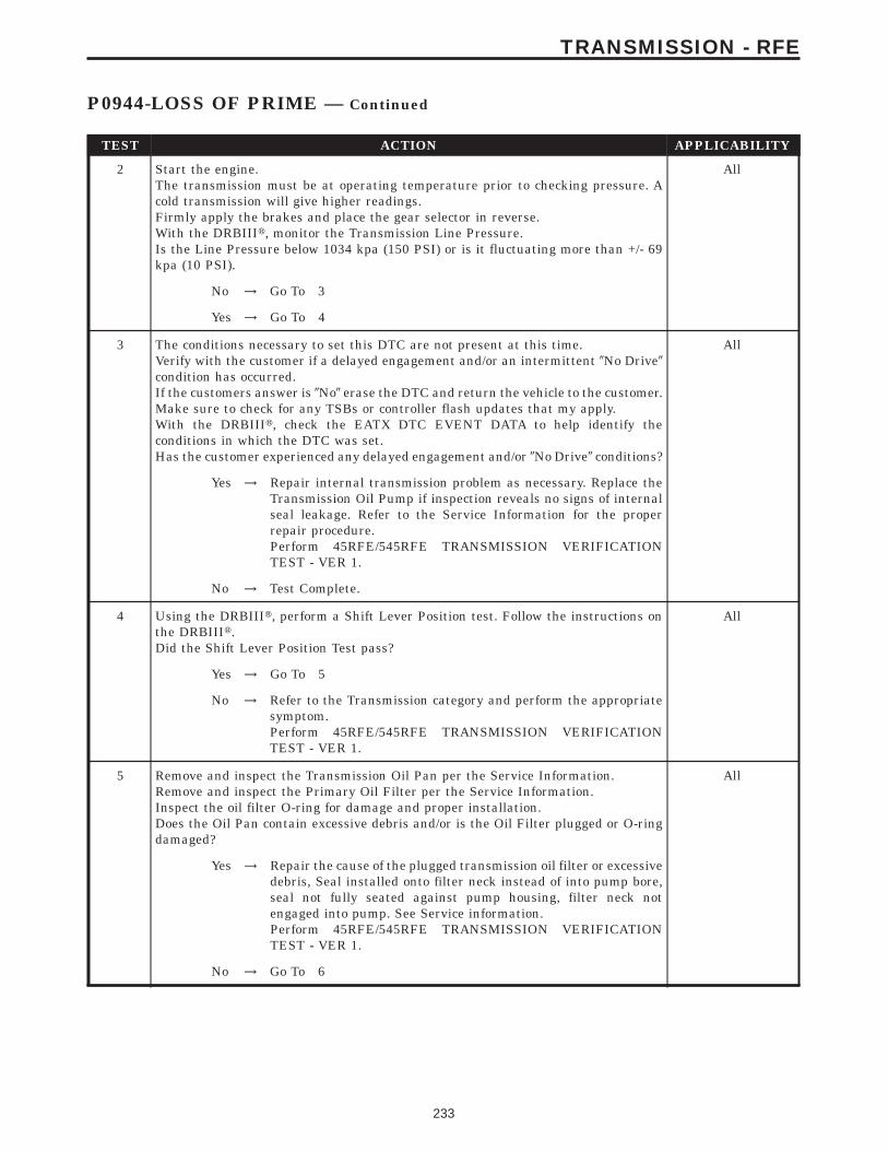
TEST ACTION APPLICABILITY
2 Start the engine.The transmission must be at operating temperature prior to checking pressure. Acold transmission will give higher readings.Firmly apply the brakes and place the gear selector in reverse.With the DRBIIIt, monitor the Transmission Line Pressure.Is the Line Pressure below 1034 kpa (150 PSI) or is it fluctuating more than +/- 69kpa (10 PSI).
All
No → Go To 3
Yes → Go To 4
3 The conditions necessary to set this DTC are not present at this time.Verify with the customer if a delayed engagement and/or an intermittent 9No Drive9condition has occurred.If the customers answer is 9No9 erase the DTC and return the vehicle to the customer.Make sure to check for any TSBs or controller flash updates that my apply.With the DRBIIIt, check the EATX DTC EVENT DATA to help identify theconditions in which the DTC was set.Has the customer experienced any delayed engagement and/or 9No Drive9 conditions?
All
Yes → Repair internal transmission problem as necessary. Replace theTransmission Oil Pump if inspection reveals no signs of internalseal leakage. Refer to the Service Information for the properrepair procedure.Perform 45RFE/545RFE TRANSMISSION VERIFICATIONTEST - VER 1.
No → Test Complete.
4 Using the DRBIIIt, perform a Shift Lever Position test. Follow the instructions onthe DRBIIIt.Did the Shift Lever Position Test pass?
All
Yes → Go To 5
No → Refer to the Transmission category and perform the appropriatesymptom.Perform 45RFE/545RFE TRANSMISSION VERIFICATIONTEST - VER 1.
5 Remove and inspect the Transmission Oil Pan per the Service Information.Remove and inspect the Primary Oil Filter per the Service Information.Inspect the oil filter O-ring for damage and proper installation.Does the Oil Pan contain excessive debris and/or is the Oil Filter plugged or O-ringdamaged?
All
Yes → Repair the cause of the plugged transmission oil filter or excessivedebris, Seal installed onto filter neck instead of into pump bore,seal not fully seated against pump housing, filter neck notengaged into pump. See Service information.Perform 45RFE/545RFE TRANSMISSION VERIFICATIONTEST - VER 1.
No → Go To 6
233
TRANSMISSION - RFE
P0944-LOSS OF PRIME — Continued
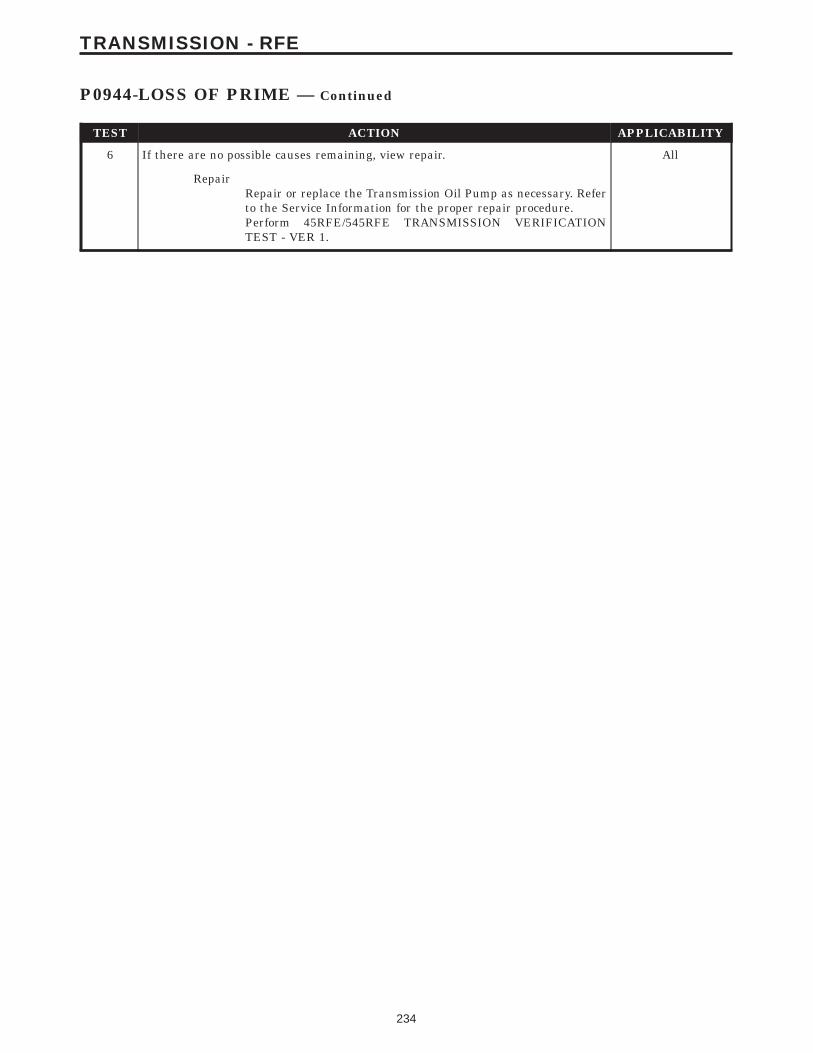
TEST ACTION APPLICABILITY
6 If there are no possible causes remaining, view repair. All
RepairRepair or replace the Transmission Oil Pump as necessary. Referto the Service Information for the proper repair procedure.Perform 45RFE/545RFE TRANSMISSION VERIFICATIONTEST - VER 1.
234
TRANSMISSION - RFE
P0944-LOSS OF PRIME — Continued
Symptom:P0987-4C HYDRAULIC PRESSURE TEST FAILURE
When Monitored and Set Condition:
P0987-4C HYDRAULIC PRESSURE TEST FAILURE
When Monitored: In any forward gear with engine speed above 1000 RPM shortly aftera shift and every minute thereafter.
Set Condition: After a shift into a forward gear, with engine speed > 1000 RPM, the TCMmomentarily turns on element pressure to the clutch circuits that don’t have pressure toidentify the correct pressure switch closes. If the pressure switch does not close 2 times theDTC sets
POSSIBLE CAUSES
LINE PRESSURE DTC’S PRESENT
POOR LINE PRESSURE SENSOR CONNECTION
4C PRESSURE SWITCH SENSE CIRCUIT OPEN
5-VOLT SUPPLY CIRCUIT OPEN
TRANSMISSION CONTROL RELAY OUTPUT CIRCUIT OPEN
4C PRESSURE SWITCH SENSE CIRCUIT SHORT TO GROUND
5-VOLT SUPPLY CIRCUIT SHORT TO GROUND
4C PRESSURE SWITCH SENSE CIRCUIT SHORT TO VOLTAGE
EXCESSIVE DEBRIS IN OIL PAN
LINE PRESSURE SENSOR
TRANSMISSION SOLENOID/TRS ASSEMBLY
INTERNAL TRANSMISSION
TRANSMISSION CONTROL MODULE
INTERMITTENT WIRING AND CONNECTORS
235
TRANSMISSION - RFE

TEST ACTION APPLICABILITY
1 NOTE: Low fluid level can be the cause of many transmission problems. Ifthe fluid level is low locate and repair the leak then check and adjust thefluid level per the Service Information.NOTE: Always perform diagnostics with a fully charged battery to avoidfalse symptoms.With the DRBIIIt, read the engine DTC’s. Check and repair all engine DTC’s priorto performing transmission symptom diagnostics.With the DRBIIIt, read Transmission DTC’s. Record all DTC’s and 1 Trip Failures.NOTE: Diagnose 1 Trip Failures as a fully matured DTC.Using the wiring diagram/schematic as a guide, inspect the wiring and connectors.Repair as necessary.Perform the Shift Lever Position Test. If the test does not pass, refer to Symptom testfor P0706 Check Shifter Signal.For Gear Ratio DTC’s, check and record all CVI’s.Most DTC’s set on start up but some must be set by driving the vehicle such that alldiagnostic monitors have run.NOTE: Verify the flash level of the transmission controller. Some problemsare corrected by software upgrades to the transmission controller.NOTE: Check for applicable TSB’s related to the problem.Perform this procedure prior to Symptom diagnosis.
All
ContinueGo To 2
2 With the DRBIIIt, check for other transmission DTC’sAre there any Line Pressure related DTC’s P0867, P0932, P0868, P0869, or P0944present?
All
Yes → Refer to the Transmission category and perform the appropriatesymptom.Perform 45RFE/545RFE TRANSMISSION VERIFICATIONTEST - VER 1.
No → Go To 3
3 With the DRBIIIt, check for other transmission DTC’sIs the DTC P0734 and/or P0988 present also?
All
Yes → Replace the Transmission Solenoid/TRS Assembly per the ServiceInformation.Perform 45RFE/545RFE TRANSMISSION VERIFICATIONTEST - VER 1.
No → Go To 4
4 With the DRBIIIt, Check the STARTS SINCE SET counter for P0987.NOTE: This counter only applies to the last DTC set.Is the STARTS SINCE SET counter 2 or less?
All
Yes → Go To 5
No → Go To 18
236
TRANSMISSION - RFE
P0987-4C HYDRAULIC PRESSURE TEST FAILURE — Continued
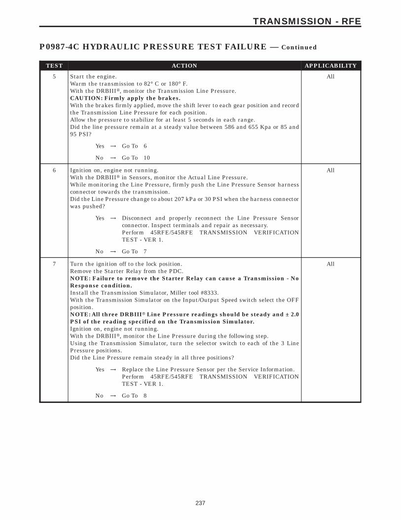
TEST ACTION APPLICABILITY
5 Start the engine.Warm the transmission to 82° C or 180° F.With the DRBIIIt, monitor the Transmission Line Pressure.CAUTION: Firmly apply the brakes.With the brakes firmly applied, move the shift lever to each gear position and recordthe Transmission Line Pressure for each position.Allow the pressure to stabilize for at least 5 seconds in each range.Did the line pressure remain at a steady value between 586 and 655 Kpa or 85 and95 PSI?
All
Yes → Go To 6
No → Go To 10
6 Ignition on, engine not running.With the DRBIIIt in Sensors, monitor the Actual Line Pressure.While monitoring the Line Pressure, firmly push the Line Pressure Sensor harnessconnector towards the transmission.Did the Line Pressure change to about 207 kPa or 30 PSI when the harness connectorwas pushed?
All
Yes → Disconnect and properly reconnect the Line Pressure Sensorconnector. Inspect terminals and repair as necessary.Perform 45RFE/545RFE TRANSMISSION VERIFICATIONTEST - VER 1.
No → Go To 7
7 Turn the ignition off to the lock position.Remove the Starter Relay from the PDC.NOTE: Failure to remove the Starter Relay can cause a Transmission - NoResponse condition.Install the Transmission Simulator, Miller tool #8333.With the Transmission Simulator on the Input/Output Speed switch select the OFFposition.NOTE: All three DRBIIIt Line Pressure readings should be steady and ± 2.0PSI of the reading specified on the Transmission Simulator.Ignition on, engine not running.With the DRBIIIt, monitor the Line Pressure during the following step.Using the Transmission Simulator, turn the selector switch to each of the 3 LinePressure positions.Did the Line Pressure remain steady in all three positions?
All
Yes → Replace the Line Pressure Sensor per the Service Information.Perform 45RFE/545RFE TRANSMISSION VERIFICATIONTEST - VER 1.
No → Go To 8
237
TRANSMISSION - RFE
P0987-4C HYDRAULIC PRESSURE TEST FAILURE — Continued
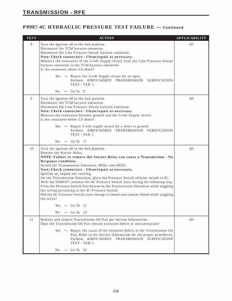
TEST ACTION APPLICABILITY
8 Turn the ignition off to the lock position.Disconnect the TCM harness connector.Disconnect the Line Pressure Sensor harness connector.Note: Check connectors - Clean/repair as necessary.Measure the resistance of the 5-volt Supply circuit from the Line Pressure Sensorharness connector to the TCM harness connector.Is the resistance above 5.0 ohms?
All
Yes → Repair the 5-volt Supply circuit for an open.Perform 45RFE/545RFE TRANSMISSION VERIFICATIONTEST - VER 1.
No → Go To 9
9 Turn the ignition off to the lock position.Disconnect the TCM harness connector.Disconnect the Line Pressure Sensor harness connector.Note: Check connectors - Clean/repair as necessary.Measure the resistance between ground and the 5-volt Supply circuit.Is the resistance below 5.0 ohms?
All
Yes → Repair 5-volt supply circuit for a short to ground.Perform 45RFE/545RFE TRANSMISSION VERIFICATIONTEST - VER 1.
No → Go To 17
10 Turn the ignition off to the lock position.Remove the Starter Relay.NOTE: Failure to remove the Starter Relay can cause a Transmission - NoResponse condition.Install the Transmission Simulator, Miller tool #8333.Note: Check connectors - Clean/repair as necessary.Ignition on, engine not running.On the Transmission Simulator, place the Pressure Switch selector switch to 4C.With the DRBIIIt, monitor the 4C Pressure Switch state during the following step.Press the Pressure Switch Test button on the Transmission Simulator while wigglingthe wiring pertaining to the 4C Pressure Switch.Did the 4C Pressure Switch state change to closed and remain closed while wigglingthe wires?
All
Yes → Go To 11
No → Go To 13
11 Remove and inspect Transmission Oil Pan per Service Information.Does the Transmission Oil Pan contain excessive debris or contamination?
All
Yes → Repair the cause of the excessive debris in the Transmission OilPan. Refer to the Service Information for the proper procedures.Perform 45RFE/545RFE TRANSMISSION VERIFICATIONTEST - VER 1.
No → Go To 12
238
TRANSMISSION - RFE
P0987-4C HYDRAULIC PRESSURE TEST FAILURE — Continued
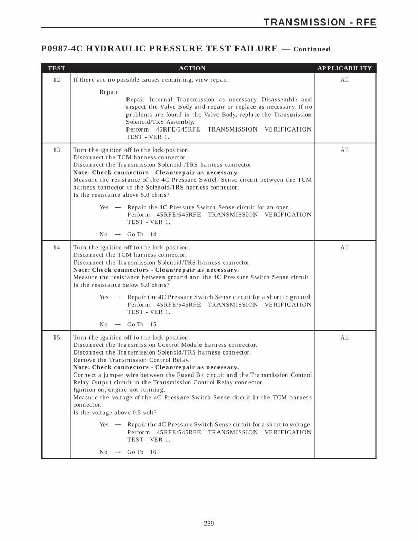
TEST ACTION APPLICABILITY
12 If there are no possible causes remaining, view repair. All
RepairRepair Internal Transmission as necessary. Disassemble andinspect the Valve Body and repair or replace as necessary. If noproblems are found in the Valve Body, replace the TransmissionSolenoid/TRS Assembly.Perform 45RFE/545RFE TRANSMISSION VERIFICATIONTEST - VER 1.
13 Turn the ignition off to the lock position.Disconnect the TCM harness connector.Disconnect the Transmission Solenoid /TRS harness connectorNote: Check connectors - Clean/repair as necessary.Measure the resistance of the 4C Pressure Switch Sense circuit between the TCMharness connector to the Solenoid/TRS harness connector.Is the resistance above 5.0 ohms?
All
Yes → Repair the 4C Pressure Switch Sense circuit for an open.Perform 45RFE/545RFE TRANSMISSION VERIFICATIONTEST - VER 1.
No → Go To 14
14 Turn the ignition off to the lock position.Disconnect the TCM harness connector.Disconnect the Transmission Solenoid/TRS harness connector.Note: Check connectors - Clean/repair as necessary.Measure the resistance between ground and the 4C Pressure Switch Sense circuit.Is the resistance below 5.0 ohms?
All
Yes → Repair the 4C Pressure Switch Sense circuit for a short to ground.Perform 45RFE/545RFE TRANSMISSION VERIFICATIONTEST - VER 1.
No → Go To 15
15 Turn the ignition off to the lock position.Disconnect the Transmission Control Module harness connector.Disconnect the Transmission Solenoid/TRS harness connector.Remove the Transmission Control Relay.Note: Check connectors - Clean/repair as necessary.Connect a jumper wire between the Fused B+ circuit and the Transmission ControlRelay Output circuit in the Transmission Control Relay connector.Ignition on, engine not running.Measure the voltage of the 4C Pressure Switch Sense circuit in the TCM harnessconnector.Is the voltage above 0.5 volt?
All
Yes → Repair the 4C Pressure Switch Sense circuit for a short to voltage.Perform 45RFE/545RFE TRANSMISSION VERIFICATIONTEST - VER 1.
No → Go To 16
239
TRANSMISSION - RFE
P0987-4C HYDRAULIC PRESSURE TEST FAILURE — Continued
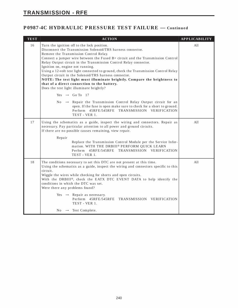
TEST ACTION APPLICABILITY
16 Turn the ignition off to the lock position.Disconnect the Transmission Solenoid/TRS harness connector.Remove the Transmission Control Relay.Connect a jumper wire between the Fused B+ circuit and the Transmission ControlRelay Output circuit in the Transmission Control Relay connector.Ignition on, engine not running.Using a 12-volt test light connected to ground, check the Transmission Control RelayOutput circuit in the Solenoid/TRS harness connector.NOTE: The test light must illuminate brightly. Compare the brightness tothat of a direct connection to the battery.Does the test light illuminate brightly?
All
Yes → Go To 17
No → Repair the Transmission Control Relay Output circuit for anopen. If the fuse is open make sure to check for a short to ground.Perform 45RFE/545RFE TRANSMISSION VERIFICATIONTEST - VER 1.
17 Using the schematics as a guide, inspect the wiring and connectors. Repair asnecessary. Pay particular attention to all power and ground circuits.If there are no possible causes remaining, view repair.
All
RepairReplace the Transmission Control Module per the Service Infor-mation. WITH THE DRBIIIt PERFORM QUICK LEARNPerform 45RFE/545RFE TRANSMISSION VERIFICATIONTEST - VER 1.
18 The conditions necessary to set this DTC are not present at this time.Using the schematics as a guide, inspect the wiring and connectors specific to thiscircuit.Wiggle the wires while checking for shorts and open circuits.With the DRBIIIt, check the EATX DTC EVENT DATA to help identify theconditions in which the DTC was set.Were there any problems found?
All
Yes → Repair as necessary.Perform 45RFE/545RFE TRANSMISSION VERIFICATIONTEST - VER 1.
No → Test Complete.
240
TRANSMISSION - RFE
P0987-4C HYDRAULIC PRESSURE TEST FAILURE — Continued
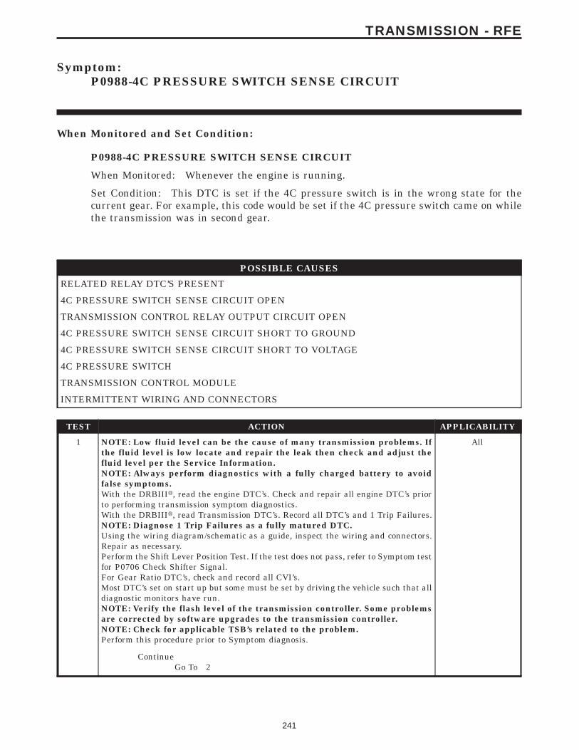
Symptom:P0988-4C PRESSURE SWITCH SENSE CIRCUIT
When Monitored and Set Condition:
P0988-4C PRESSURE SWITCH SENSE CIRCUIT
When Monitored: Whenever the engine is running.
Set Condition: This DTC is set if the 4C pressure switch is in the wrong state for thecurrent gear. For example, this code would be set if the 4C pressure switch came on whilethe transmission was in second gear.
POSSIBLE CAUSES
RELATED RELAY DTC’S PRESENT
4C PRESSURE SWITCH SENSE CIRCUIT OPEN
TRANSMISSION CONTROL RELAY OUTPUT CIRCUIT OPEN
4C PRESSURE SWITCH SENSE CIRCUIT SHORT TO GROUND
4C PRESSURE SWITCH SENSE CIRCUIT SHORT TO VOLTAGE
4C PRESSURE SWITCH
TRANSMISSION CONTROL MODULE
INTERMITTENT WIRING AND CONNECTORS
TEST ACTION APPLICABILITY
1 NOTE: Low fluid level can be the cause of many transmission problems. Ifthe fluid level is low locate and repair the leak then check and adjust thefluid level per the Service Information.NOTE: Always perform diagnostics with a fully charged battery to avoidfalse symptoms.With the DRBIIIt, read the engine DTC’s. Check and repair all engine DTC’s priorto performing transmission symptom diagnostics.With the DRBIIIt, read Transmission DTC’s. Record all DTC’s and 1 Trip Failures.NOTE: Diagnose 1 Trip Failures as a fully matured DTC.Using the wiring diagram/schematic as a guide, inspect the wiring and connectors.Repair as necessary.Perform the Shift Lever Position Test. If the test does not pass, refer to Symptom testfor P0706 Check Shifter Signal.For Gear Ratio DTC’s, check and record all CVI’s.Most DTC’s set on start up but some must be set by driving the vehicle such that alldiagnostic monitors have run.NOTE: Verify the flash level of the transmission controller. Some problemsare corrected by software upgrades to the transmission controller.NOTE: Check for applicable TSB’s related to the problem.Perform this procedure prior to Symptom diagnosis.
All
ContinueGo To 2
241
TRANSMISSION - RFE

TEST ACTION APPLICABILITY
2 With the DRBIIIt, check for other transmission DTC’s.Are there any Transmission Control Relay related DTC’s P0890, P0891, or P0888present?
All
Yes → Refer to the Transmission category and perform the appropriatesymptom.Perform 45RFE/545RFE TRANSMISSION VERIFICATIONTEST - VER 1.
No → Go To 3
3 Ignition on, engine not running.With the DRBIIIt, Check the STARTS SINCE SET counter.NOTE: This counter only applies to the last DTC set.Is the STARTS SINCE SET counter for P0988, 2 or less?
All
Yes → Go To 4
No → Go To 11
4 Turn the ignition off to the lock position.Remove the Starter Relay.NOTE: Failure to remove the Starter Relay can cause a Transmission - NoResponse condition.Install the Transmission Simulator, Miller tool #8333.Note: Check connectors - Clean/repair as necessary.Ignition on, engine not running.With the Transmission Simulator turn the Pressure Switch selector switch to 4C.With the DRBIIIt, monitor the 4C Pressure Switch state while pressing the PressureSwitch Test button.Did the state of the 4C Pressure Switch change while pressing the Pressure SwitchTest button?
All
Yes → Go To 5
No → Go To 6
5 If there are no possible causes remaining, view repair. All
RepairReplace the Transmission Solenoid/TRS Assembly per the ServiceInformation.Perform 45RFE/545RFE TRANSMISSION VERIFICATIONTEST - VER 1.
6 Turn the ignition off to the lock position.Disconnect the TCM harness connector.Disconnect the Transmission Solenoid /TRS Assembly harness connectorNote: Check connectors - Clean/repair as necessary.Measure the resistance of the 4C Pressure Switch Sense circuit from the TCMharness connector to the Transmission Solenoid/TRS Assembly harness connector.Is the resistance above 5.0 ohms?
All
Yes → Repair the 4C Pressure Switch Sense circuit for an open.Perform 45RFE/545RFE TRANSMISSION VERIFICATIONTEST - VER 1.
No → Go To 7
242
TRANSMISSION - RFE
P0988-4C PRESSURE SWITCH SENSE CIRCUIT — Continued
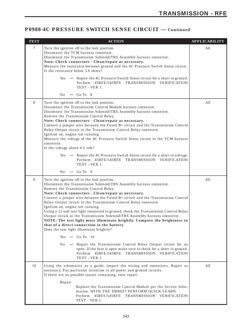
TEST ACTION APPLICABILITY
7 Turn the ignition off to the lock position.Disconnect the TCM harness connector.Disconnect the Transmission Solenoid/TRS Assembly harness connector.Note: Check connectors - Clean/repair as necessary.Measure the resistance between ground and the 4C Pressure Switch Sense circuit.Is the resistance below 5.0 ohms?
All
Yes → Repair the 4C Pressure Switch Sense circuit for a short to ground.Perform 45RFE/545RFE TRANSMISSION VERIFICATIONTEST - VER 1.
No → Go To 8
8 Turn the ignition off to the lock position.Disconnect the Transmission Control Module harness connector.Disconnect the Transmission Solenoid/TRS Assembly harness connector.Remove the Transmission Control Relay.Note: Check connectors - Clean/repair as necessary.Connect a jumper wire between the Fused B+ circuit and the Transmission ControlRelay Output circuit in the Transmission Control Relay connector.Ignition on, engine not running.Measure the voltage of the 4C Pressure Switch Sense circuit in the TCM harnessconnector.Is the voltage above 0.5 volt?
All
Yes → Repair the 4C Pressure Switch Sense circuit for a short to voltage.Perform 45RFE/545RFE TRANSMISSION VERIFICATIONTEST - VER 1.
No → Go To 9
9 Turn the ignition off to the lock position.Disconnect the Transmission Solenoid/TRS Assembly harness connector.Remove the Transmission Control Relay.Note: Check connectors - Clean/repair as necessary.Connect a jumper wire between the Fused B+ circuit and the Transmission ControlRelay Output circuit in the Transmission Control Relay connector.Ignition on, engine not running.Using a 12-volt test light connected to ground, check the Transmission Control RelayOutput circuit in the Transmission Solenoid/TRS Assembly harness connector.NOTE: The test light must illuminate brightly. Compare the brightness tothat of a direct connection to the battery.Does the test light illuminate brightly?
All
Yes → Go To 10
No → Repair the Transmission Control Relay Output circuit for anopen. If the fuse is open make sure to check for a short to ground.Perform 45RFE/545RFE TRANSMISSION VERIFICATIONTEST - VER 1.
10 Using the schematics as a guide, inspect the wiring and connectors. Repair asnecessary. Pay particular attention to all power and ground circuits.If there are no possible causes remaining, view repair.
All
RepairReplace the Transmission Control Module per the Service Infor-mation. WITH THE DRBIIIt PERFORM QUICK LEARNPerform 45RFE/545RFE TRANSMISSION VERIFICATIONTEST - VER 1.
243
TRANSMISSION - RFE
P0988-4C PRESSURE SWITCH SENSE CIRCUIT — Continued

TEST ACTION APPLICABILITY
11 The conditions necessary to set this DTC are not present at this time.Using the schematics as a guide, inspect the wiring and connectors specific to thiscircuit.Wiggle the wires while checking for shorts and open circuits.Check for a Primary Oil filter installed incorrectly.A dislodged Reverse Carrier Snap Ring will typically set this DTC on heavy throttleacceleration from a dead stop.With the DRBIIIt, check the EATX DTC EVENT DATA to help identify theconditions in which the DTC was set.Were there any problems found?
All
Yes → Repair as necessary.Perform 45RFE/545RFE TRANSMISSION VERIFICATIONTEST - VER 1.
No → Test Complete.
244
TRANSMISSION - RFE
P0988-4C PRESSURE SWITCH SENSE CIRCUIT — Continued
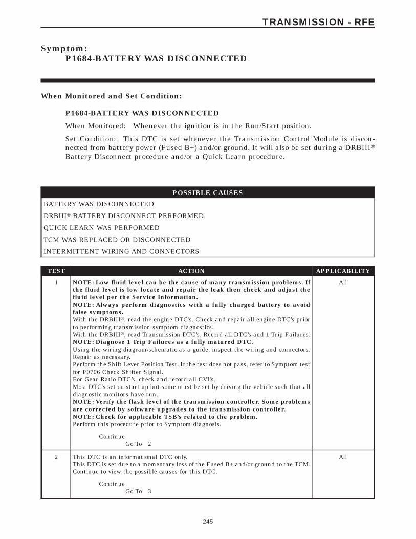
Symptom:P1684-BATTERY WAS DISCONNECTED
When Monitored and Set Condition:
P1684-BATTERY WAS DISCONNECTED
When Monitored: Whenever the ignition is in the Run/Start position.
Set Condition: This DTC is set whenever the Transmission Control Module is discon-nected from battery power (Fused B+) and/or ground. It will also be set during a DRBIIItBattery Disconnect procedure and/or a Quick Learn procedure.
POSSIBLE CAUSES
BATTERY WAS DISCONNECTED
DRBIIIt BATTERY DISCONNECT PERFORMED
QUICK LEARN WAS PERFORMED
TCM WAS REPLACED OR DISCONNECTED
INTERMITTENT WIRING AND CONNECTORS
TEST ACTION APPLICABILITY
1 NOTE: Low fluid level can be the cause of many transmission problems. Ifthe fluid level is low locate and repair the leak then check and adjust thefluid level per the Service Information.NOTE: Always perform diagnostics with a fully charged battery to avoidfalse symptoms.With the DRBIIIt, read the engine DTC’s. Check and repair all engine DTC’s priorto performing transmission symptom diagnostics.With the DRBIIIt, read Transmission DTC’s. Record all DTC’s and 1 Trip Failures.NOTE: Diagnose 1 Trip Failures as a fully matured DTC.Using the wiring diagram/schematic as a guide, inspect the wiring and connectors.Repair as necessary.Perform the Shift Lever Position Test. If the test does not pass, refer to Symptom testfor P0706 Check Shifter Signal.For Gear Ratio DTC’s, check and record all CVI’s.Most DTC’s set on start up but some must be set by driving the vehicle such that alldiagnostic monitors have run.NOTE: Verify the flash level of the transmission controller. Some problemsare corrected by software upgrades to the transmission controller.NOTE: Check for applicable TSB’s related to the problem.Perform this procedure prior to Symptom diagnosis.
All
ContinueGo To 2
2 This DTC is an informational DTC only.This DTC is set due to a momentary loss of the Fused B+ and/or ground to the TCM.Continue to view the possible causes for this DTC.
All
ContinueGo To 3
245
TRANSMISSION - RFE
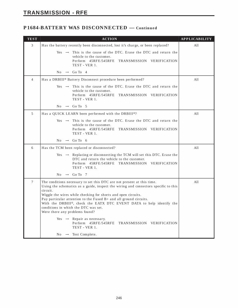
TEST ACTION APPLICABILITY
3 Has the battery recently been disconnected, lost it’s charge, or been replaced? All
Yes → This is the cause of the DTC. Erase the DTC and return thevehicle to the customer.Perform 45RFE/545RFE TRANSMISSION VERIFICATIONTEST - VER 1.
No → Go To 4
4 Has a DRBIIIt Battery Disconnect procedure been performed? All
Yes → This is the cause of the DTC. Erase the DTC and return thevehicle to the customer.Perform 45RFE/545RFE TRANSMISSION VERIFICATIONTEST - VER 1.
No → Go To 5
5 Has a QUICK LEARN been performed with the DRBIIIt? All
Yes → This is the cause of the DTC. Erase the DTC and return thevehicle to the customer.Perform 45RFE/545RFE TRANSMISSION VERIFICATIONTEST - VER 1.
No → Go To 6
6 Has the TCM been replaced or disconnected? All
Yes → Replacing or disconnecting the TCM will set this DTC. Erase theDTC and return the vehicle to the customer.Perform 45RFE/545RFE TRANSMISSION VERIFICATIONTEST - VER 1.
No → Go To 7
7 The conditions necessary to set this DTC are not present at this time.Using the schematics as a guide, inspect the wiring and connectors specific to thiscircuit.Wiggle the wires while checking for shorts and open circuits.Pay particular attention to the Fused B+ and all ground circuits.With the DRBIIIt, check the EATX DTC EVENT DATA to help identify theconditions in which the DTC was set.Were there any problems found?
All
Yes → Repair as necessary.Perform 45RFE/545RFE TRANSMISSION VERIFICATIONTEST - VER 1.
No → Test Complete.
246
TRANSMISSION - RFE
P1684-BATTERY WAS DISCONNECTED — Continued
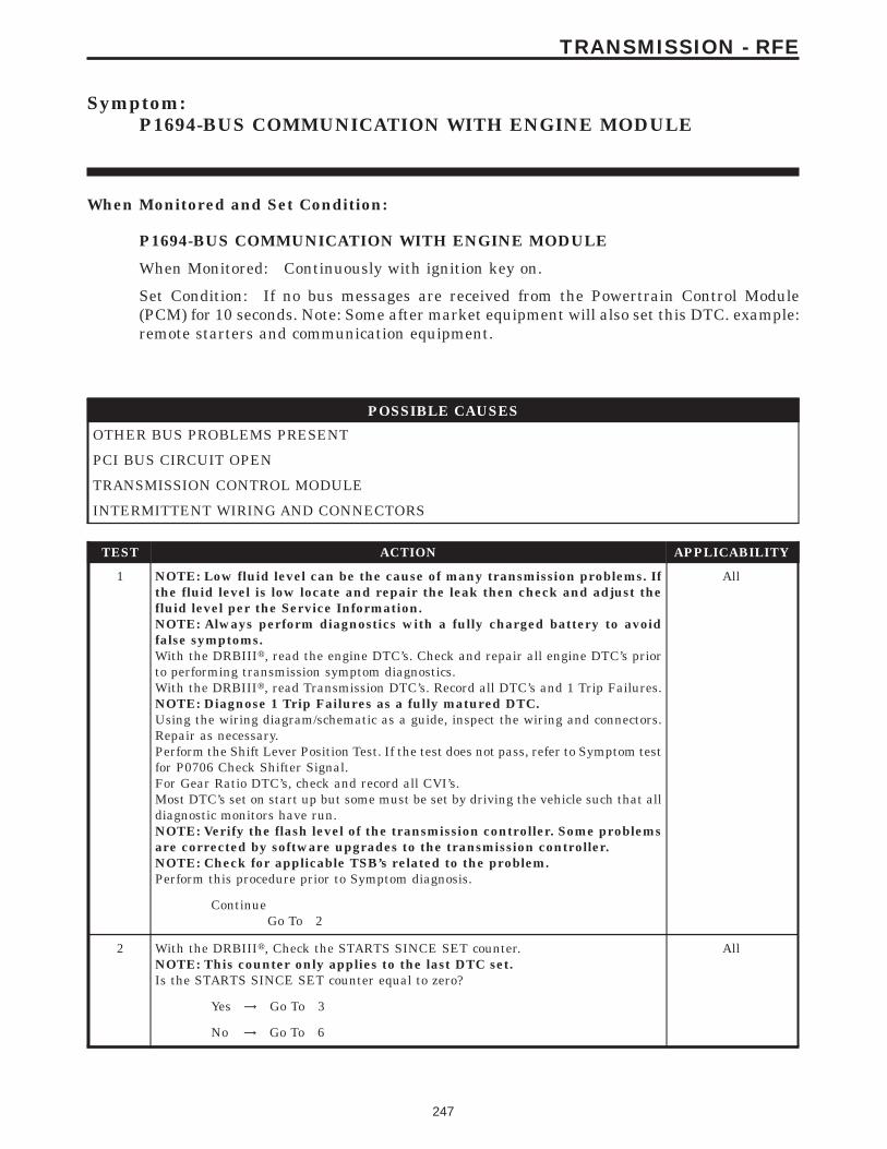
Symptom:P1694-BUS COMMUNICATION WITH ENGINE MODULE
When Monitored and Set Condition:
P1694-BUS COMMUNICATION WITH ENGINE MODULE
When Monitored: Continuously with ignition key on.
Set Condition: If no bus messages are received from the Powertrain Control Module(PCM) for 10 seconds. Note: Some after market equipment will also set this DTC. example:remote starters and communication equipment.
POSSIBLE CAUSES
OTHER BUS PROBLEMS PRESENT
PCI BUS CIRCUIT OPEN
TRANSMISSION CONTROL MODULE
INTERMITTENT WIRING AND CONNECTORS
TEST ACTION APPLICABILITY
1 NOTE: Low fluid level can be the cause of many transmission problems. Ifthe fluid level is low locate and repair the leak then check and adjust thefluid level per the Service Information.NOTE: Always perform diagnostics with a fully charged battery to avoidfalse symptoms.With the DRBIIIt, read the engine DTC’s. Check and repair all engine DTC’s priorto performing transmission symptom diagnostics.With the DRBIIIt, read Transmission DTC’s. Record all DTC’s and 1 Trip Failures.NOTE: Diagnose 1 Trip Failures as a fully matured DTC.Using the wiring diagram/schematic as a guide, inspect the wiring and connectors.Repair as necessary.Perform the Shift Lever Position Test. If the test does not pass, refer to Symptom testfor P0706 Check Shifter Signal.For Gear Ratio DTC’s, check and record all CVI’s.Most DTC’s set on start up but some must be set by driving the vehicle such that alldiagnostic monitors have run.NOTE: Verify the flash level of the transmission controller. Some problemsare corrected by software upgrades to the transmission controller.NOTE: Check for applicable TSB’s related to the problem.Perform this procedure prior to Symptom diagnosis.
All
ContinueGo To 2
2 With the DRBIIIt, Check the STARTS SINCE SET counter.NOTE: This counter only applies to the last DTC set.Is the STARTS SINCE SET counter equal to zero?
All
Yes → Go To 3
No → Go To 6
247
TRANSMISSION - RFE
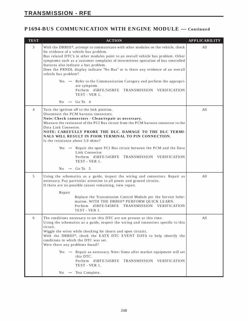
TEST ACTION APPLICABILITY
3 With the DRBIIIt, attempt to communicate with other modules on the vehicle, checkfor evidence of a vehicle bus problem.Bus related DTC’s in other modules point to an overall vehicle bus problem. Othersymptoms such as a customer complaint of intermittent operation of bus controlledfeatures also indicate a bus problem.Does the PRNDL display indicate 9No Bus9 or is there any evidence of an overallvehicle bus problem?
All
Yes → Refer to the Communication Category and perform the appropri-ate symptom.Perform 45RFE/545RFE TRANSMISSION VERIFICATIONTEST - VER 1.
No → Go To 4
4 Turn the ignition off to the lock position.Disconnect the PCM harness connectors.Note: Check connectors - Clean/repair as necessary.Measure the resistance of the PCI Bus circuit from the PCM harness connector to theData Link Connector.NOTE: CAREFULLY PROBE THE DLC. DAMAGE TO THE DLC TERMI-NALS WILL RESULT IN POOR TERMINAL TO PIN CONNECTION.Is the resistance above 5.0 ohms?
All
Yes → Repair the open PCI Bus circuit between the PCM and the DataLink Connector.Perform 45RFE/545RFE TRANSMISSION VERIFICATIONTEST - VER 1.
No → Go To 5
5 Using the schematics as a guide, inspect the wiring and connectors. Repair asnecessary. Pay particular attention to all power and ground circuits.If there are no possible causes remaining, view repair.
All
RepairReplace the Transmission Control Module per the Service Infor-mation. WITH THE DRBIIIt PERFORM QUICK LEARN.Perform 45RFE/545RFE TRANSMISSION VERIFICATIONTEST - VER 1.
6 The conditions necessary to set this DTC are not present at this time.Using the schematics as a guide, inspect the wiring and connectors specific to thiscircuit.Wiggle the wires while checking for shorts and open circuits.With the DRBIIIt, check the EATX DTC EVENT DATA to help identify theconditions in which the DTC was set.Were there any problems found?
All
Yes → Repair as necessary. Note: Some after market equipment will setthis DTC.Perform 45RFE/545RFE TRANSMISSION VERIFICATIONTEST - VER 1.
No → Test Complete.
248
TRANSMISSION - RFE
P1694-BUS COMMUNICATION WITH ENGINE MODULE — Continued
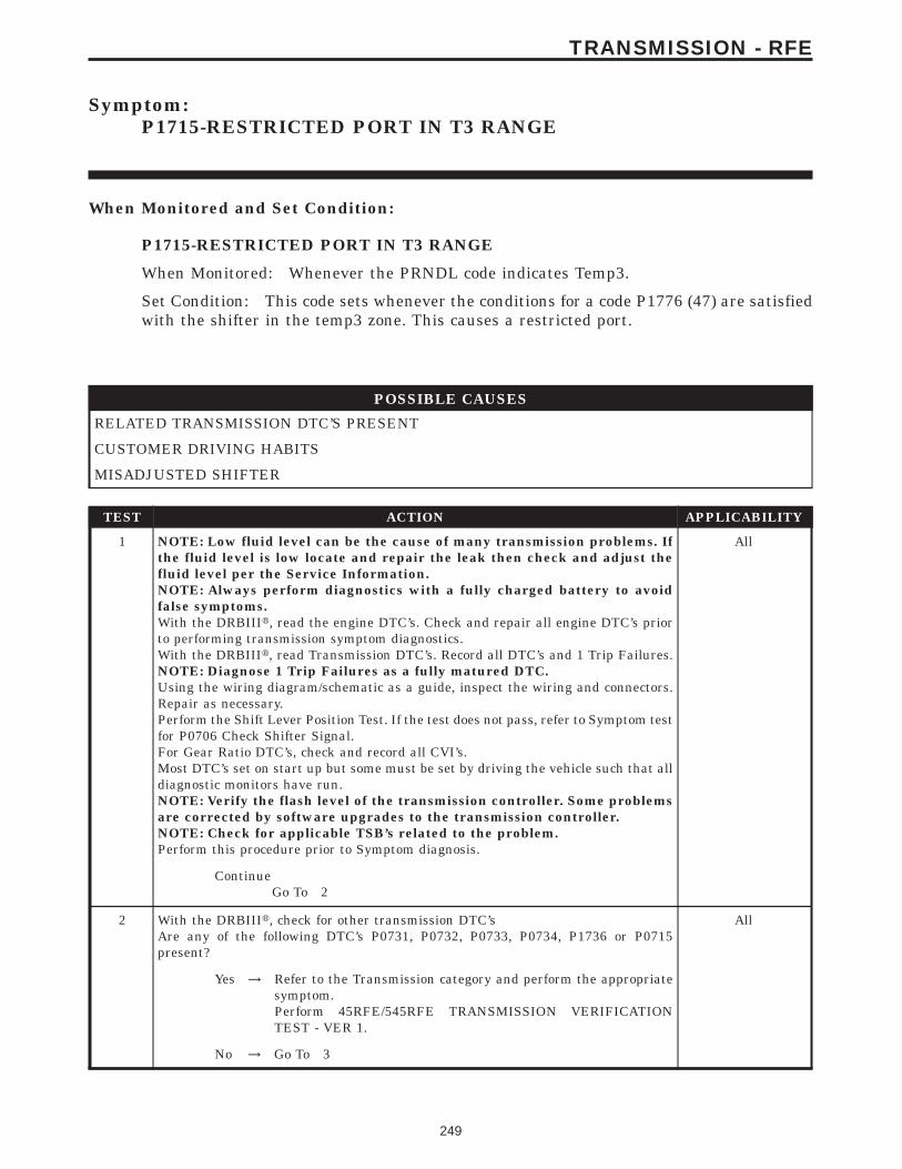
Symptom:P1715-RESTRICTED PORT IN T3 RANGE
When Monitored and Set Condition:
P1715-RESTRICTED PORT IN T3 RANGE
When Monitored: Whenever the PRNDL code indicates Temp3.
Set Condition: This code sets whenever the conditions for a code P1776 (47) are satisfiedwith the shifter in the temp3 zone. This causes a restricted port.
POSSIBLE CAUSES
RELATED TRANSMISSION DTC’S PRESENT
CUSTOMER DRIVING HABITS
MISADJUSTED SHIFTER
TEST ACTION APPLICABILITY
1 NOTE: Low fluid level can be the cause of many transmission problems. Ifthe fluid level is low locate and repair the leak then check and adjust thefluid level per the Service Information.NOTE: Always perform diagnostics with a fully charged battery to avoidfalse symptoms.With the DRBIIIt, read the engine DTC’s. Check and repair all engine DTC’s priorto performing transmission symptom diagnostics.With the DRBIIIt, read Transmission DTC’s. Record all DTC’s and 1 Trip Failures.NOTE: Diagnose 1 Trip Failures as a fully matured DTC.Using the wiring diagram/schematic as a guide, inspect the wiring and connectors.Repair as necessary.Perform the Shift Lever Position Test. If the test does not pass, refer to Symptom testfor P0706 Check Shifter Signal.For Gear Ratio DTC’s, check and record all CVI’s.Most DTC’s set on start up but some must be set by driving the vehicle such that alldiagnostic monitors have run.NOTE: Verify the flash level of the transmission controller. Some problemsare corrected by software upgrades to the transmission controller.NOTE: Check for applicable TSB’s related to the problem.Perform this procedure prior to Symptom diagnosis.
All
ContinueGo To 2
2 With the DRBIIIt, check for other transmission DTC’sAre any of the following DTC’s P0731, P0732, P0733, P0734, P1736 or P0715present?
All
Yes → Refer to the Transmission category and perform the appropriatesymptom.Perform 45RFE/545RFE TRANSMISSION VERIFICATIONTEST - VER 1.
No → Go To 3
249
TRANSMISSION - RFE
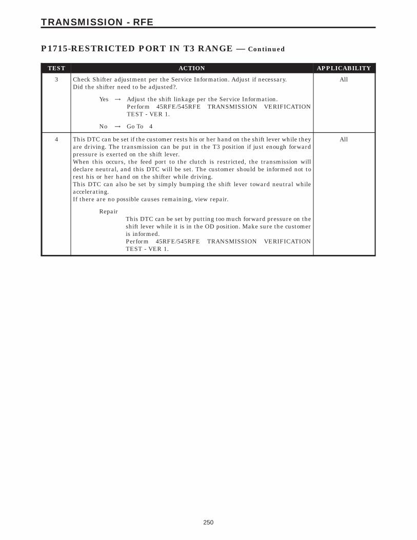
TEST ACTION APPLICABILITY
3 Check Shifter adjustment per the Service Information. Adjust if necessary.Did the shifter need to be adjusted?.
All
Yes → Adjust the shift linkage per the Service Information.Perform 45RFE/545RFE TRANSMISSION VERIFICATIONTEST - VER 1.
No → Go To 4
4 This DTC can be set if the customer rests his or her hand on the shift lever while theyare driving. The transmission can be put in the T3 position if just enough forwardpressure is exerted on the shift lever.When this occurs, the feed port to the clutch is restricted, the transmission willdeclare neutral, and this DTC will be set. The customer should be informed not torest his or her hand on the shifter while driving.This DTC can also be set by simply bumping the shift lever toward neutral whileaccelerating.If there are no possible causes remaining, view repair.
All
RepairThis DTC can be set by putting too much forward pressure on theshift lever while it is in the OD position. Make sure the customeris informed.Perform 45RFE/545RFE TRANSMISSION VERIFICATIONTEST - VER 1.
250
TRANSMISSION - RFE
P1715-RESTRICTED PORT IN T3 RANGE — Continued

Symptom:P1736-GEAR RATIO ERROR IN 2ND PRIME
When Monitored and Set Condition:
P1736-GEAR RATIO ERROR IN 2ND PRIME
When Monitored: The transmission gear ratio is monitored continuously while thetransmission is in gear.
Set Condition: If the ratio of the Input RPM to the Output RPM does not match thecurrent gear ratio. This DTC can take up to five minutes of problem identification beforeilluminating the MIL.
POSSIBLE CAUSES
RELATED DTC’S PRESENT
INTERNAL TRANSMISSION
INTERMITTENT GEAR RATIO ERRORS
TEST ACTION APPLICABILITY
1 NOTE: Low fluid level can be the cause of many transmission problems. Ifthe fluid level is low locate and repair the leak then check and adjust thefluid level per the Service Information.NOTE: Always perform diagnostics with a fully charged battery to avoidfalse symptoms.With the DRBIIIt, read the engine DTC’s. Check and repair all engine DTC’s priorto performing transmission symptom diagnostics.With the DRBIIIt, read Transmission DTC’s. Record all DTC’s and 1 Trip Failures.NOTE: Diagnose 1 Trip Failures as a fully matured DTC.Using the wiring diagram/schematic as a guide, inspect the wiring and connectors.Repair as necessary.Perform the Shift Lever Position Test. If the test does not pass, refer to Symptom testfor P0706 Check Shifter Signal.For Gear Ratio DTC’s, check and record all CVI’s.Most DTC’s set on start up but some must be set by driving the vehicle such that alldiagnostic monitors have run.NOTE: Verify the flash level of the transmission controller. Some problemsare corrected by software upgrades to the transmission controller.NOTE: Check for applicable TSB’s related to the problem.Perform this procedure prior to Symptom diagnosis.
All
ContinueGo To 2
251
TRANSMISSION - RFE
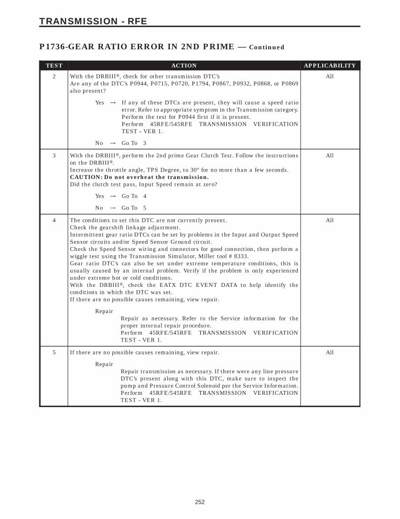
TEST ACTION APPLICABILITY
2 With the DRBIIIt, check for other transmission DTC’sAre any of the DTC’s P0944, P0715, P0720, P1794, P0867, P0932, P0868, or P0869also present?
All
Yes → If any of these DTCs are present, they will cause a speed ratioerror. Refer to appropriate symptom in the Transmission category.Perform the test for P0944 first if it is present.Perform 45RFE/545RFE TRANSMISSION VERIFICATIONTEST - VER 1.
No → Go To 3
3 With the DRBIIIt, perform the 2nd prime Gear Clutch Test. Follow the instructionson the DRBIIIt.Increase the throttle angle, TPS Degree, to 30° for no more than a few seconds.CAUTION: Do not overheat the transmission.Did the clutch test pass, Input Speed remain at zero?
All
Yes → Go To 4
No → Go To 5
4 The conditions to set this DTC are not currently present.Check the gearshift linkage adjustment.Intermittent gear ratio DTCs can be set by problems in the Input and Output SpeedSensor circuits and/or Speed Sensor Ground circuit.Check the Speed Sensor wiring and connectors for good connection, then perform awiggle test using the Transmission Simulator, Miller tool # 8333.Gear ratio DTC’s can also be set under extreme temperature conditions, this isusually caused by an internal problem. Verify if the problem is only experiencedunder extreme hot or cold conditions.With the DRBIIIt, check the EATX DTC EVENT DATA to help identify theconditions in which the DTC was set.If there are no possible causes remaining, view repair.
All
RepairRepair as necessary. Refer to the Service information for theproper internal repair procedure.Perform 45RFE/545RFE TRANSMISSION VERIFICATIONTEST - VER 1.
5 If there are no possible causes remaining, view repair. All
RepairRepair transmission as necessary. If there were any line pressureDTC’s present along with this DTC, make sure to inspect thepump and Pressure Control Solenoid per the Service Information.Perform 45RFE/545RFE TRANSMISSION VERIFICATIONTEST - VER 1.
252
TRANSMISSION - RFE
P1736-GEAR RATIO ERROR IN 2ND PRIME — Continued
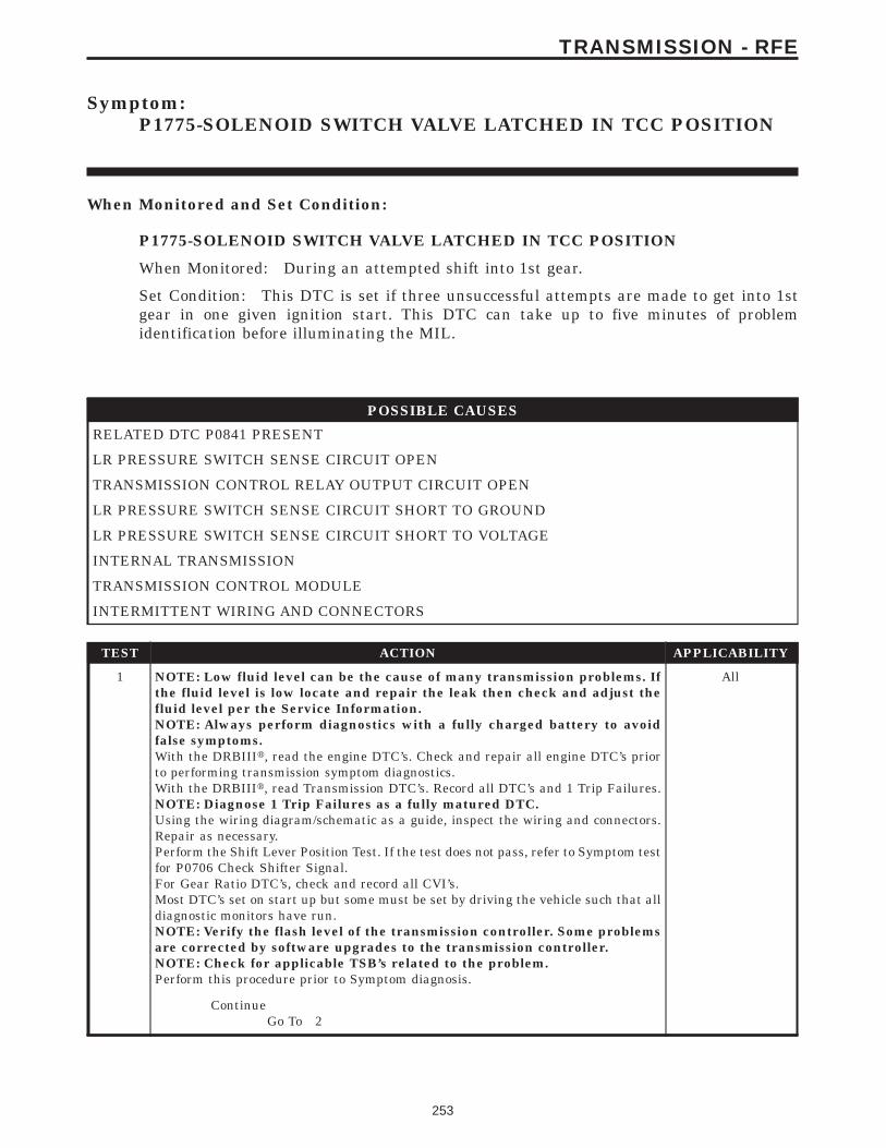
Symptom:P1775-SOLENOID SWITCH VALVE LATCHED IN TCC POSITION
When Monitored and Set Condition:
P1775-SOLENOID SWITCH VALVE LATCHED IN TCC POSITION
When Monitored: During an attempted shift into 1st gear.
Set Condition: This DTC is set if three unsuccessful attempts are made to get into 1stgear in one given ignition start. This DTC can take up to five minutes of problemidentification before illuminating the MIL.
POSSIBLE CAUSES
RELATED DTC P0841 PRESENT
LR PRESSURE SWITCH SENSE CIRCUIT OPEN
TRANSMISSION CONTROL RELAY OUTPUT CIRCUIT OPEN
LR PRESSURE SWITCH SENSE CIRCUIT SHORT TO GROUND
LR PRESSURE SWITCH SENSE CIRCUIT SHORT TO VOLTAGE
INTERNAL TRANSMISSION
TRANSMISSION CONTROL MODULE
INTERMITTENT WIRING AND CONNECTORS
TEST ACTION APPLICABILITY
1 NOTE: Low fluid level can be the cause of many transmission problems. Ifthe fluid level is low locate and repair the leak then check and adjust thefluid level per the Service Information.NOTE: Always perform diagnostics with a fully charged battery to avoidfalse symptoms.With the DRBIIIt, read the engine DTC’s. Check and repair all engine DTC’s priorto performing transmission symptom diagnostics.With the DRBIIIt, read Transmission DTC’s. Record all DTC’s and 1 Trip Failures.NOTE: Diagnose 1 Trip Failures as a fully matured DTC.Using the wiring diagram/schematic as a guide, inspect the wiring and connectors.Repair as necessary.Perform the Shift Lever Position Test. If the test does not pass, refer to Symptom testfor P0706 Check Shifter Signal.For Gear Ratio DTC’s, check and record all CVI’s.Most DTC’s set on start up but some must be set by driving the vehicle such that alldiagnostic monitors have run.NOTE: Verify the flash level of the transmission controller. Some problemsare corrected by software upgrades to the transmission controller.NOTE: Check for applicable TSB’s related to the problem.Perform this procedure prior to Symptom diagnosis.
All
ContinueGo To 2
253
TRANSMISSION - RFE
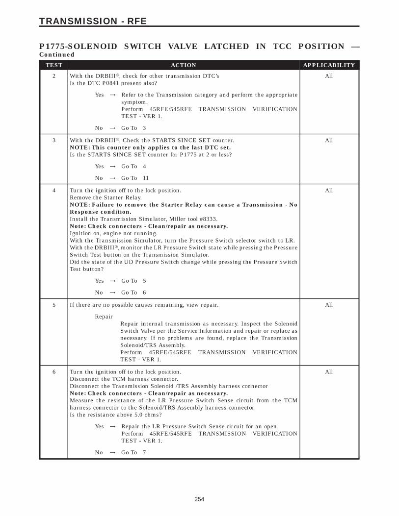
TEST ACTION APPLICABILITY
2 With the DRBIIIt, check for other transmission DTC’sIs the DTC P0841 present also?
All
Yes → Refer to the Transmission category and perform the appropriatesymptom.Perform 45RFE/545RFE TRANSMISSION VERIFICATIONTEST - VER 1.
No → Go To 3
3 With the DRBIIIt, Check the STARTS SINCE SET counter.NOTE: This counter only applies to the last DTC set.Is the STARTS SINCE SET counter for P1775 at 2 or less?
All
Yes → Go To 4
No → Go To 11
4 Turn the ignition off to the lock position.Remove the Starter Relay.NOTE: Failure to remove the Starter Relay can cause a Transmission - NoResponse condition.Install the Transmission Simulator, Miller tool #8333.Note: Check connectors - Clean/repair as necessary.Ignition on, engine not running.With the Transmission Simulator, turn the Pressure Switch selector switch to LR.With the DRBIIIt, monitor the LR Pressure Switch state while pressing the PressureSwitch Test button on the Transmission Simulator.Did the state of the UD Pressure Switch change while pressing the Pressure SwitchTest button?
All
Yes → Go To 5
No → Go To 6
5 If there are no possible causes remaining, view repair. All
RepairRepair internal transmission as necessary. Inspect the SolenoidSwitch Valve per the Service Information and repair or replace asnecessary. If no problems are found, replace the TransmissionSolenoid/TRS Assembly.Perform 45RFE/545RFE TRANSMISSION VERIFICATIONTEST - VER 1.
6 Turn the ignition off to the lock position.Disconnect the TCM harness connector.Disconnect the Transmission Solenoid /TRS Assembly harness connectorNote: Check connectors - Clean/repair as necessary.Measure the resistance of the LR Pressure Switch Sense circuit from the TCMharness connector to the Solenoid/TRS Assembly harness connector.Is the resistance above 5.0 ohms?
All
Yes → Repair the LR Pressure Switch Sense circuit for an open.Perform 45RFE/545RFE TRANSMISSION VERIFICATIONTEST - VER 1.
No → Go To 7
254
TRANSMISSION - RFE
P1775-SOLENOID SWITCH VALVE LATCHED IN TCC POSITION —Continued
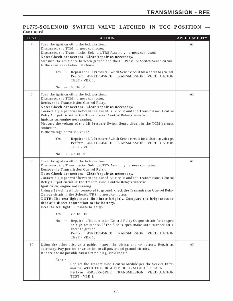
TEST ACTION APPLICABILITY
7 Turn the ignition off to the lock position.Disconnect the TCM harness connector.Disconnect the Transmission Solenoid/TRS Assembly harness connector.Note: Check connectors - Clean/repair as necessary.Measure the resistance between ground and the LR Pressure Switch Sense circuit.Is the resistance below 5.0 ohms?
All
Yes → Repair the LR Pressure Switch Sense circuit for a short to ground.Perform 45RFE/545RFE TRANSMISSION VERIFICATIONTEST - VER 1.
No → Go To 8
8 Turn the ignition off to the lock position.Disconnect the TCM harness connector.Remove the Transmission Control Relay.Note: Check connectors - Clean/repair as necessary.Connect a jumper wire between the Fused B+ circuit and the Transmission ControlRelay Output circuit in the Transmission Control Relay connector.Ignition on, engine not running.Measure the voltage of the LR Pressure Switch Sense circuit in the TCM harnessconnector.Is the voltage above 0.5 volts?
All
Yes → Repair the LR Pressure Switch Sense circuit for a short to voltage.Perform 45RFE/545RFE TRANSMISSION VERIFICATIONTEST - VER 1.
No → Go To 9
9 Turn the ignition off to the lock position.Disconnect the Transmission Solenoid/TRS Assembly harness connector.Remove the Transmission Control Relay.Note: Check connectors - Clean/repair as necessary.Connect a jumper wire between the Fused B+ circuit and the Transmission ControlRelay Output circuit in the Transmission Control Relay connector.Ignition on, engine not running.Using a 12-volt test light connected to ground, check the Transmission Control RelayOutput circuit in the Solenoid/TRS harness connector.NOTE: The test light must illuminate brightly. Compare the brightness tothat of a direct connection to the battery.Does the test light illuminate brightly?
All
Yes → Go To 10
No → Repair the Transmission Control Relay Output circuit for an openor high resistance. If the fuse is open make sure to check for ashort to ground.Perform 45RFE/545RFE TRANSMISSION VERIFICATIONTEST - VER 1.
10 Using the schematics as a guide, inspect the wiring and connectors. Repair asnecessary. Pay particular attention to all power and ground circuits.If there are no possible causes remaining, view repair.
All
RepairReplace the Transmission Control Module per the Service Infor-mation. WITH THE DRBIIIt PERFORM QUICK LEARNPerform 45RFE/545RFE TRANSMISSION VERIFICATIONTEST - VER 1.
255
TRANSMISSION - RFE
P1775-SOLENOID SWITCH VALVE LATCHED IN TCC POSITION —Continued
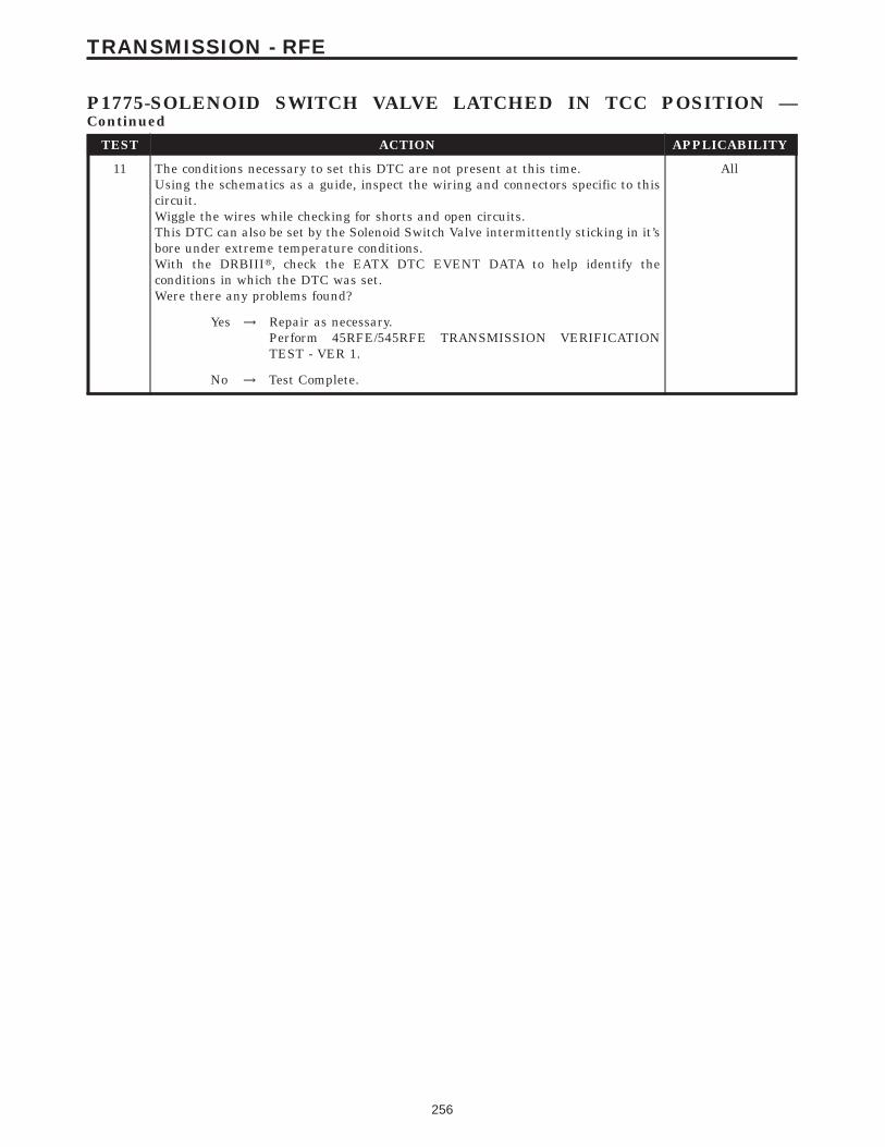
TEST ACTION APPLICABILITY
11 The conditions necessary to set this DTC are not present at this time.Using the schematics as a guide, inspect the wiring and connectors specific to thiscircuit.Wiggle the wires while checking for shorts and open circuits.This DTC can also be set by the Solenoid Switch Valve intermittently sticking in it’sbore under extreme temperature conditions.With the DRBIIIt, check the EATX DTC EVENT DATA to help identify theconditions in which the DTC was set.Were there any problems found?
All
Yes → Repair as necessary.Perform 45RFE/545RFE TRANSMISSION VERIFICATIONTEST - VER 1.
No → Test Complete.
256
TRANSMISSION - RFE
P1775-SOLENOID SWITCH VALVE LATCHED IN TCC POSITION —Continued
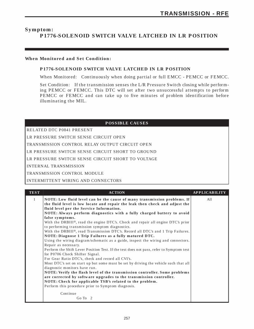
Symptom:P1776-SOLENOID SWITCH VALVE LATCHED IN LR POSITION
When Monitored and Set Condition:
P1776-SOLENOID SWITCH VALVE LATCHED IN LR POSITION
When Monitored: Continuously when doing partial or full EMCC - PEMCC or FEMCC.
Set Condition: If the transmission senses the L/R Pressure Switch closing while perform-ing PEMCC or FEMCC. This DTC will set after two unsuccessful attempts to performPEMCC or FEMCC and can take up to five minutes of problem identification beforeilluminating the MIL.
POSSIBLE CAUSES
RELATED DTC P0841 PRESENT
LR PRESSURE SWITCH SENSE CIRCUIT OPEN
TRANSMISSION CONTROL RELAY OUTPUT CIRCUIT OPEN
LR PRESSURE SWITCH SENSE CIRCUIT SHORT TO GROUND
LR PRESSURE SWITCH SENSE CIRCUIT SHORT TO VOLTAGE
INTERNAL TRANSMISSION
TRANSMISSION CONTROL MODULE
INTERMITTENT WIRING AND CONNECTORS
TEST ACTION APPLICABILITY
1 NOTE: Low fluid level can be the cause of many transmission problems. Ifthe fluid level is low locate and repair the leak then check and adjust thefluid level per the Service Information.NOTE: Always perform diagnostics with a fully charged battery to avoidfalse symptoms.With the DRBIIIt, read the engine DTC’s. Check and repair all engine DTC’s priorto performing transmission symptom diagnostics.With the DRBIIIt, read Transmission DTC’s. Record all DTC’s and 1 Trip Failures.NOTE: Diagnose 1 Trip Failures as a fully matured DTC.Using the wiring diagram/schematic as a guide, inspect the wiring and connectors.Repair as necessary.Perform the Shift Lever Position Test. If the test does not pass, refer to Symptom testfor P0706 Check Shifter Signal.For Gear Ratio DTC’s, check and record all CVI’s.Most DTC’s set on start up but some must be set by driving the vehicle such that alldiagnostic monitors have run.NOTE: Verify the flash level of the transmission controller. Some problemsare corrected by software upgrades to the transmission controller.NOTE: Check for applicable TSB’s related to the problem.Perform this procedure prior to Symptom diagnosis.
All
ContinueGo To 2
257
TRANSMISSION - RFE
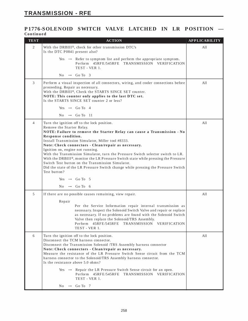
TEST ACTION APPLICABILITY
2 With the DRBIIIt, check for other transmission DTC’sIs the DTC P0841 present also?
All
Yes → Refer to symptom list and perform the appropriate symptom.Perform 45RFE/545RFE TRANSMISSION VERIFICATIONTEST - VER 1.
No → Go To 3
3 Perform a visual inspection of all connectors, wiring, and cooler connections beforeproceeding. Repair as necessary.With the DRBIIIt, Check the STARTS SINCE SET counter.NOTE: This counter only applies to the last DTC set.Is the STARTS SINCE SET counter 2 or less?
All
Yes → Go To 4
No → Go To 11
4 Turn the ignition off to the lock position.Remove the Starter Relay.NOTE: Failure to remove the Starter Relay can cause a Transmission - NoResponse condition.Install Transmission Simulator, Miller tool #8333.Note: Check connectors - Clean/repair as necessary.Ignition on, engine not running.With the Transmission Simulator, turn the Pressure Switch selector switch to LR.With the DRBIIIt, monitor the LR Pressure Switch state while pressing the PressureSwitch Test button on the Transmission Simulator.Did the state of the LR Pressure Switch change while pressing the Pressure SwitchTest button?
All
Yes → Go To 5
No → Go To 6
5 If there are no possible causes remaining, view repair. All
RepairPer the Service Information repair internal transmission asnecessary. Inspect the Solenoid Switch Valve and repair or replaceas necessary. If no problems are found with the Solenoid SwitchValve then replace the Solenoid/TRS Assembly.Perform 45RFE/545RFE TRANSMISSION VERIFICATIONTEST - VER 1.
6 Turn the ignition off to the lock position.Disconnect the TCM harness connector.Disconnect the Transmission Solenoid /TRS Assembly harness connectorNote: Check connectors - Clean/repair as necessary.Measure the resistance of the LR Pressure Switch Sense circuit from the TCMharness connector to the Solenoid/TRS Assembly harness connector.Is the resistance above 5.0 ohms?
All
Yes → Repair the LR Pressure Switch Sense circuit for an open.Perform 45RFE/545RFE TRANSMISSION VERIFICATIONTEST - VER 1.
No → Go To 7
258
TRANSMISSION - RFE
P1776-SOLENOID SWITCH VALVE LATCHED IN LR POSITION —Continued
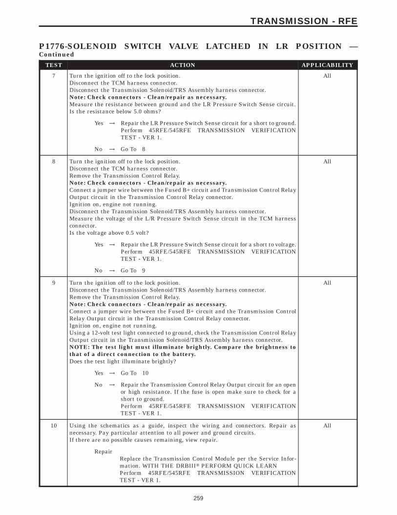
TEST ACTION APPLICABILITY
7 Turn the ignition off to the lock position.Disconnect the TCM harness connector.Disconnect the Transmission Solenoid/TRS Assembly harness connector.Note: Check connectors - Clean/repair as necessary.Measure the resistance between ground and the LR Pressure Switch Sense circuit.Is the resistance below 5.0 ohms?
All
Yes → Repair the LR Pressure Switch Sense circuit for a short to ground.Perform 45RFE/545RFE TRANSMISSION VERIFICATIONTEST - VER 1.
No → Go To 8
8 Turn the ignition off to the lock position.Disconnect the TCM harness connector.Remove the Transmission Control Relay.Note: Check connectors - Clean/repair as necessary.Connect a jumper wire between the Fused B+ circuit and Transmission Control RelayOutput circuit in the Transmission Control Relay connector.Ignition on, engine not running.Disconnect the Transmission Solenoid/TRS Assembly harness connector.Measure the voltage of the L/R Pressure Switch Sense circuit in the TCM harnessconnector.Is the voltage above 0.5 volt?
All
Yes → Repair the LR Pressure Switch Sense circuit for a short to voltage.Perform 45RFE/545RFE TRANSMISSION VERIFICATIONTEST - VER 1.
No → Go To 9
9 Turn the ignition off to the lock position.Disconnect the Transmission Solenoid/TRS Assembly harness connector.Remove the Transmission Control Relay.Note: Check connectors - Clean/repair as necessary.Connect a jumper wire between the Fused B+ circuit and the Transmission ControlRelay Output circuit in the Transmission Control Relay connector.Ignition on, engine not running.Using a 12-volt test light connected to ground, check the Transmission Control RelayOutput circuit in the Transmission Solenoid/TRS Assembly harness connector.NOTE: The test light must illuminate brightly. Compare the brightness tothat of a direct connection to the battery.Does the test light illuminate brightly?
All
Yes → Go To 10
No → Repair the Transmission Control Relay Output circuit for an openor high resistance. If the fuse is open make sure to check for ashort to ground.Perform 45RFE/545RFE TRANSMISSION VERIFICATIONTEST - VER 1.
10 Using the schematics as a guide, inspect the wiring and connectors. Repair asnecessary. Pay particular attention to all power and ground circuits.If there are no possible causes remaining, view repair.
All
RepairReplace the Transmission Control Module per the Service Infor-mation. WITH THE DRBIIIt PERFORM QUICK LEARNPerform 45RFE/545RFE TRANSMISSION VERIFICATIONTEST - VER 1.
259
TRANSMISSION - RFE
P1776-SOLENOID SWITCH VALVE LATCHED IN LR POSITION —Continued

TEST ACTION APPLICABILITY
11 The conditions necessary to set this DTC are not present at this time.Using the schematics as a guide, inspect the wiring and connectors specific to thiscircuit.Wiggle the wires while checking for shorts and open circuits.This DTC can also be set by the Solenoid Switch Valve intermittently sticking in it’sbore under extreme temperature conditions.With the DRBIIIt, check the EATX DTC EVENT DATA to help identify theconditions in which the DTC was set.Were there any problems found?
All
Yes → Repair as necessary.Perform 45RFE/545RFE TRANSMISSION VERIFICATIONTEST - VER 1.
No → Test Complete.
260
TRANSMISSION - RFE
P1776-SOLENOID SWITCH VALVE LATCHED IN LR POSITION —Continued
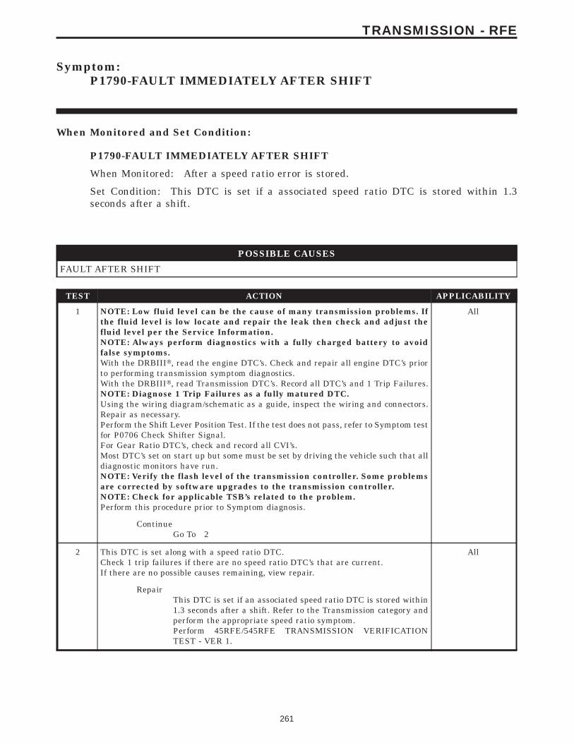
Symptom:P1790-FAULT IMMEDIATELY AFTER SHIFT
When Monitored and Set Condition:
P1790-FAULT IMMEDIATELY AFTER SHIFT
When Monitored: After a speed ratio error is stored.
Set Condition: This DTC is set if a associated speed ratio DTC is stored within 1.3seconds after a shift.
POSSIBLE CAUSES
FAULT AFTER SHIFT
TEST ACTION APPLICABILITY
1 NOTE: Low fluid level can be the cause of many transmission problems. Ifthe fluid level is low locate and repair the leak then check and adjust thefluid level per the Service Information.NOTE: Always perform diagnostics with a fully charged battery to avoidfalse symptoms.With the DRBIIIt, read the engine DTC’s. Check and repair all engine DTC’s priorto performing transmission symptom diagnostics.With the DRBIIIt, read Transmission DTC’s. Record all DTC’s and 1 Trip Failures.NOTE: Diagnose 1 Trip Failures as a fully matured DTC.Using the wiring diagram/schematic as a guide, inspect the wiring and connectors.Repair as necessary.Perform the Shift Lever Position Test. If the test does not pass, refer to Symptom testfor P0706 Check Shifter Signal.For Gear Ratio DTC’s, check and record all CVI’s.Most DTC’s set on start up but some must be set by driving the vehicle such that alldiagnostic monitors have run.NOTE: Verify the flash level of the transmission controller. Some problemsare corrected by software upgrades to the transmission controller.NOTE: Check for applicable TSB’s related to the problem.Perform this procedure prior to Symptom diagnosis.
All
ContinueGo To 2
2 This DTC is set along with a speed ratio DTC.Check 1 trip failures if there are no speed ratio DTC’s that are current.If there are no possible causes remaining, view repair.
All
RepairThis DTC is set if an associated speed ratio DTC is stored within1.3 seconds after a shift. Refer to the Transmission category andperform the appropriate speed ratio symptom.Perform 45RFE/545RFE TRANSMISSION VERIFICATIONTEST - VER 1.
261
TRANSMISSION - RFE
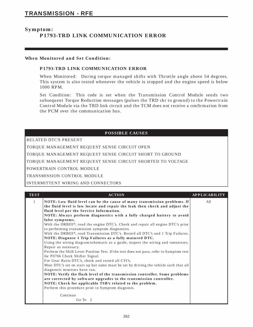
Symptom:P1793-TRD LINK COMMUNICATION ERROR
When Monitored and Set Condition:
P1793-TRD LINK COMMUNICATION ERROR
When Monitored: During torque managed shifts with Throttle angle above 54 degrees.This system is also tested whenever the vehicle is stopped and the engine speed is below1000 RPM.
Set Condition: This code is set when the Transmission Control Module sends twosubsequent Torque Reduction messages (pulses the TRD ckt to ground) to the PowertrainControl Module via the TRD link circuit and the TCM does not receive a confirmation fromthe PCM over the communication bus.
POSSIBLE CAUSES
RELATED DTC’S PRESENT
TORQUE MANAGEMENT REQUEST SENSE CIRCUIT OPEN
TORQUE MANAGEMENT REQUEST SENSE CIRCUIT SHORT TO GROUND
TORQUE MANAGEMENT REQUEST SENSE CIRCUIT SHORTED TO VOLTAGE
POWERTRAIN CONTROL MODULE
TRANSMISSION CONTROL MODULE
INTERMITTENT WIRING AND CONNECTORS
TEST ACTION APPLICABILITY
1 NOTE: Low fluid level can be the cause of many transmission problems. Ifthe fluid level is low locate and repair the leak then check and adjust thefluid level per the Service Information.NOTE: Always perform diagnostics with a fully charged battery to avoidfalse symptoms.With the DRBIIIt, read the engine DTC’s. Check and repair all engine DTC’s priorto performing transmission symptom diagnostics.With the DRBIIIt, read Transmission DTC’s. Record all DTC’s and 1 Trip Failures.NOTE: Diagnose 1 Trip Failures as a fully matured DTC.Using the wiring diagram/schematic as a guide, inspect the wiring and connectors.Repair as necessary.Perform the Shift Lever Position Test. If the test does not pass, refer to Symptom testfor P0706 Check Shifter Signal.For Gear Ratio DTC’s, check and record all CVI’s.Most DTC’s set on start up but some must be set by driving the vehicle such that alldiagnostic monitors have run.NOTE: Verify the flash level of the transmission controller. Some problemsare corrected by software upgrades to the transmission controller.NOTE: Check for applicable TSB’s related to the problem.Perform this procedure prior to Symptom diagnosis.
All
ContinueGo To 2
262
TRANSMISSION - RFE
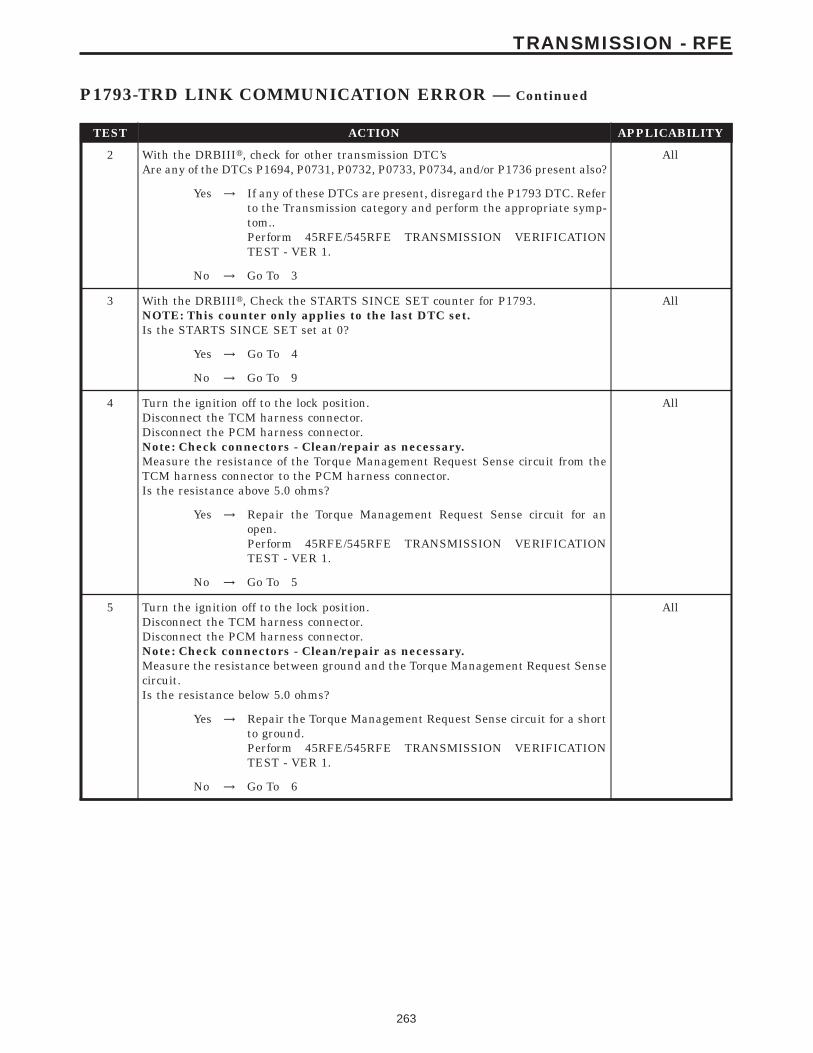
TEST ACTION APPLICABILITY
2 With the DRBIIIt, check for other transmission DTC’sAre any of the DTCs P1694, P0731, P0732, P0733, P0734, and/or P1736 present also?
All
Yes → If any of these DTCs are present, disregard the P1793 DTC. Referto the Transmission category and perform the appropriate symp-tom..Perform 45RFE/545RFE TRANSMISSION VERIFICATIONTEST - VER 1.
No → Go To 3
3 With the DRBIIIt, Check the STARTS SINCE SET counter for P1793.NOTE: This counter only applies to the last DTC set.Is the STARTS SINCE SET set at 0?
All
Yes → Go To 4
No → Go To 9
4 Turn the ignition off to the lock position.Disconnect the TCM harness connector.Disconnect the PCM harness connector.Note: Check connectors - Clean/repair as necessary.Measure the resistance of the Torque Management Request Sense circuit from theTCM harness connector to the PCM harness connector.Is the resistance above 5.0 ohms?
All
Yes → Repair the Torque Management Request Sense circuit for anopen.Perform 45RFE/545RFE TRANSMISSION VERIFICATIONTEST - VER 1.
No → Go To 5
5 Turn the ignition off to the lock position.Disconnect the TCM harness connector.Disconnect the PCM harness connector.Note: Check connectors - Clean/repair as necessary.Measure the resistance between ground and the Torque Management Request Sensecircuit.Is the resistance below 5.0 ohms?
All
Yes → Repair the Torque Management Request Sense circuit for a shortto ground.Perform 45RFE/545RFE TRANSMISSION VERIFICATIONTEST - VER 1.
No → Go To 6
263
TRANSMISSION - RFE
P1793-TRD LINK COMMUNICATION ERROR — Continued
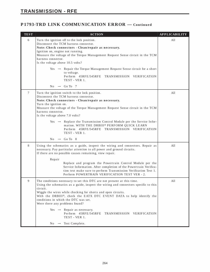
TEST ACTION APPLICABILITY
6 Turn the ignition off to the lock position.Disconnect the TCM harness connector.Note: Check connectors - Clean/repair as necessary.Ignition on, engine not running.Measure the voltage of the Torque Management Request Sense circuit in the TCMharness connector.Is the voltage above 10.5 volts?
All
Yes → Repair the Torque Management Request Sense circuit for a shortto voltage.Perform 45RFE/545RFE TRANSMISSION VERIFICATIONTEST - VER 1.
No → Go To 7
7 Turn the ignition switch to the lock position.Disconnect the TCM harness connector.Note: Check connectors - Clean/repair as necessary.Turn the ignition on.Measure the voltage of the Torque Management Request Sense circuit in the TCMharness connector.Is the voltage above 7.0 volts?
All
Yes → Replace the Transmission Control Module per the Service Infor-mation. WITH THE DRBIIIt PERFORM QUICK LEARNPerform 45RFE/545RFE TRANSMISSION VERIFICATIONTEST - VER 1.
No → Go To 8
8 Using the schematics as a guide, inspect the wiring and connectors. Repair asnecessary. Pay particular attention to all power and ground circuits.If there are no possible causes remaining, view repair.
All
RepairReplace and program the Powertrain Control Module per theService Information. After completion of the Powertrain Verifica-tion test make sure to perform Transmission Verification Test 1.Perform POWERTRAIN VERIFICATION TEST VER - 2.
9 The conditions necessary to set this DTC are not present at this time.Using the schematics as a guide, inspect the wiring and connectors specific to thiscircuit.Wiggle the wires while checking for shorts and open circuits.With the DRBIIIt, check the EATX DTC EVENT DATA to help identify theconditions in which the DTC was set.Were there any problems found?
All
Yes → Repair as necessary.Perform 45RFE/545RFE TRANSMISSION VERIFICATIONTEST - VER 1.
No → Test Complete.
264
TRANSMISSION - RFE
P1793-TRD LINK COMMUNICATION ERROR — Continued
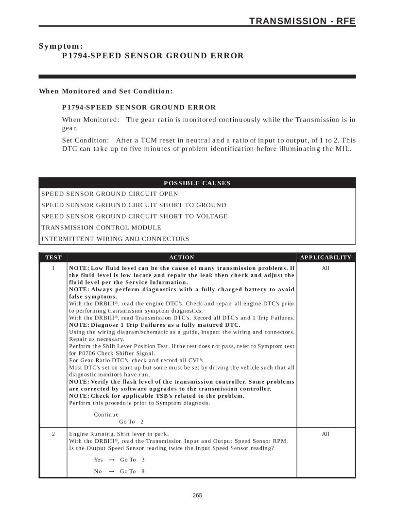
Symptom:P1794-SPEED SENSOR GROUND ERROR
When Monitored and Set Condition:
P1794-SPEED SENSOR GROUND ERROR
When Monitored: The gear ratio is monitored continuously while the Transmission is ingear.
Set Condition: After a TCM reset in neutral and a ratio of input to output, of 1 to 2. ThisDTC can take up to five minutes of problem identification before illuminating the MIL.
POSSIBLE CAUSES
SPEED SENSOR GROUND CIRCUIT OPEN
SPEED SENSOR GROUND CIRCUIT SHORT TO GROUND
SPEED SENSOR GROUND CIRCUIT SHORT TO VOLTAGE
TRANSMISSION CONTROL MODULE
INTERMITTENT WIRING AND CONNECTORS
TEST ACTION APPLICABILITY
1 NOTE: Low fluid level can be the cause of many transmission problems. Ifthe fluid level is low locate and repair the leak then check and adjust thefluid level per the Service Information.NOTE: Always perform diagnostics with a fully charged battery to avoidfalse symptoms.With the DRBIIIt, read the engine DTC’s. Check and repair all engine DTC’s priorto performing transmission symptom diagnostics.With the DRBIIIt, read Transmission DTC’s. Record all DTC’s and 1 Trip Failures.NOTE: Diagnose 1 Trip Failures as a fully matured DTC.Using the wiring diagram/schematic as a guide, inspect the wiring and connectors.Repair as necessary.Perform the Shift Lever Position Test. If the test does not pass, refer to Symptom testfor P0706 Check Shifter Signal.For Gear Ratio DTC’s, check and record all CVI’s.Most DTC’s set on start up but some must be set by driving the vehicle such that alldiagnostic monitors have run.NOTE: Verify the flash level of the transmission controller. Some problemsare corrected by software upgrades to the transmission controller.NOTE: Check for applicable TSB’s related to the problem.Perform this procedure prior to Symptom diagnosis.
All
ContinueGo To 2
2 Engine Running. Shift lever in park.With the DRBIIIt, read the Transmission Input and Output Speed Sensor RPM.Is the Output Speed Sensor reading twice the Input Speed Sensor reading?
All
Yes → Go To 3
No → Go To 8
265
TRANSMISSION - RFE
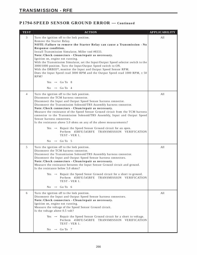
TEST ACTION APPLICABILITY
3 Turn the ignition off to the lock position.Remove the Starter Relay.NOTE: Failure to remove the Starter Relay can cause a Transmission - NoResponse condition.Install Transmission Simulator, Miller tool #8333.Note: Check connectors - Clean/repair as necessary.Ignition on, engine not running.With the Transmission Simulator, set the Input/Output Speed selector switch to the3000/1000 position. Turn the Input/Output Speed switch to ON.With the DRBIIIt, monitor the Input and Output Speed Sensor RPM.Does the Input Speed read 3000 RPM and the Output Speed read 1000 RPM, ± 50RPM?
All
Yes → Go To 8
No → Go To 4
4 Turn the ignition off to the lock position.Disconnect the TCM harness connector.Disconnect the Input and Output Speed Sensor harness connector.Disconnect the Transmission Solenoid/TRS Assembly harness connector.Note: Check connectors - Clean/repair as necessary.Measure the resistance of the Speed Sensor Ground circuit from the TCM harnessconnector to the Transmission Solenoid/TRS Assembly, Input and Output SpeedSensor harness connectors.Is the resistance above 5.0 ohms on any of the above measurements?
All
Yes → Repair the Speed Sensor Ground circuit for an open.Perform 45RFE/545RFE TRANSMISSION VERIFICATIONTEST - VER 1.
No → Go To 5
5 Turn the ignition off to the lock position.Disconnect the TCM harness connector.Disconnect the Transmission Solenoid/TRS Assembly harness connector.Disconnect the Input and Output Speed Sensor harness connectors.Note: Check connectors - Clean/repair as necessary.Measure the resistance between the Input Sensor Ground circuit and ground.Is the resistance below 5.0 ohms?
All
Yes → Repair the Speed Senor Ground circuit for a short to ground.Perform 45RFE/545RFE TRANSMISSION VERIFICATIONTEST - VER 1.
No → Go To 6
6 Turn the ignition off to the lock position.Disconnect the Input and Output Speed Sensor harness connectors.Note: Check connectors - Clean/repair as necessary.Ignition on, engine not running.Measure the voltage of the Speed Sensor Ground circuit.Is the voltage above 0.5 volt?
All
Yes → Repair the Speed Sensor Ground circuit for a short to voltage.Perform 45RFE/545RFE TRANSMISSION VERIFICATIONTEST - VER 1.
No → Go To 7
266
TRANSMISSION - RFE
P1794-SPEED SENSOR GROUND ERROR — Continued

TEST ACTION APPLICABILITY
7 Using the schematics as a guide, inspect the wiring and connectors. Repair asnecessary. Pay particular attention to all power and ground circuits.If there are no possible causes remaining, view repair.
All
RepairReplace the Transmission Control Module per the Service Infor-mation. WITH THE DRBIIIt PERFORM QUICK LEARNPerform 45RFE/545RFE TRANSMISSION VERIFICATIONTEST - VER 1.
8 The conditions necessary to set this DTC are not present at this time.Using the schematics as a guide, inspect the wiring and connectors specific to thiscircuit.Wiggle the wires while checking for shorts and open circuits.With the DRBIIIt, check the EATX DTC EVENT DATA to help identify theconditions in which the DTC was set.Were there any problems found?
All
Yes → Repair as necessary.Perform 45RFE/545RFE TRANSMISSION VERIFICATIONTEST - VER 1.
No → Test Complete.
267
TRANSMISSION - RFE
P1794-SPEED SENSOR GROUND ERROR — Continued
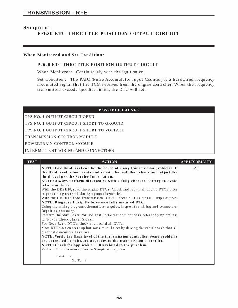
Symptom:P2620-ETC THROTTLE POSITION OUTPUT CIRCUIT
When Monitored and Set Condition:
P2620-ETC THROTTLE POSITION OUTPUT CIRCUIT
When Monitored: Continuously with the ignition on.
Set Condition: The PAIC (Pulse Accumulator Input Counter) is a hardwired frequencymodulated signal that the TCM receives from the engine controller. When the frequencytransmitted exceeds specified limits, the DTC will set.
POSSIBLE CAUSES
TPS NO. 1 OUTPUT CIRCUIT OPEN
TPS NO. 1 OUTPUT CIRCUIT SHORT TO GROUND
TPS NO. 1 OUTPUT CIRCUIT SHORT TO VOLTAGE
TRANSMISSION CONTROL MODULE
POWERTRAIN CONTROL MODULE
INTERMITTENT WIRING AND CONNECTORS
TEST ACTION APPLICABILITY
1 NOTE: Low fluid level can be the cause of many transmission problems. Ifthe fluid level is low locate and repair the leak then check and adjust thefluid level per the Service Information.NOTE: Always perform diagnostics with a fully charged battery to avoidfalse symptoms.With the DRBIIIt, read the engine DTC’s. Check and repair all engine DTC’s priorto performing transmission symptom diagnostics.With the DRBIIIt, read Transmission DTC’s. Record all DTC’s and 1 Trip Failures.NOTE: Diagnose 1 Trip Failures as a fully matured DTC.Using the wiring diagram/schematic as a guide, inspect the wiring and connectors.Repair as necessary.Perform the Shift Lever Position Test. If the test does not pass, refer to Symptom testfor P0706 Check Shifter Signal.For Gear Ratio DTC’s, check and record all CVI’s.Most DTC’s set on start up but some must be set by driving the vehicle such that alldiagnostic monitors have run.NOTE: Verify the flash level of the transmission controller. Some problemsare corrected by software upgrades to the transmission controller.NOTE: Check for applicable TSB’s related to the problem.Perform this procedure prior to Symptom diagnosis.
All
ContinueGo To 2
268
TRANSMISSION - RFE
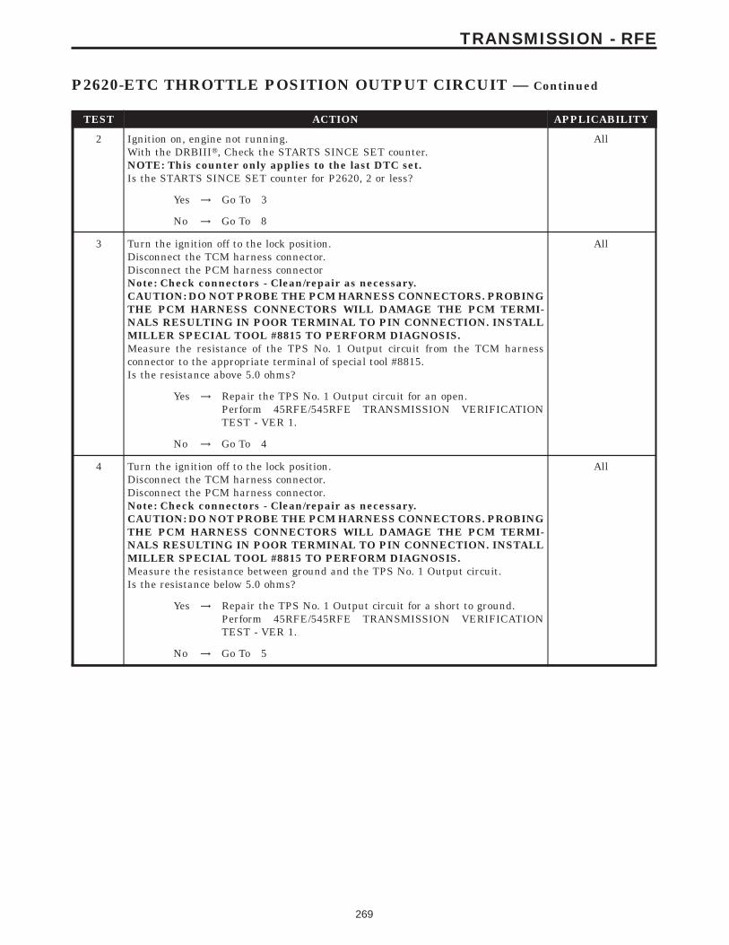
TEST ACTION APPLICABILITY
2 Ignition on, engine not running.With the DRBIIIt, Check the STARTS SINCE SET counter.NOTE: This counter only applies to the last DTC set.Is the STARTS SINCE SET counter for P2620, 2 or less?
All
Yes → Go To 3
No → Go To 8
3 Turn the ignition off to the lock position.Disconnect the TCM harness connector.Disconnect the PCM harness connectorNote: Check connectors - Clean/repair as necessary.CAUTION: DO NOT PROBE THE PCM HARNESS CONNECTORS. PROBINGTHE PCM HARNESS CONNECTORS WILL DAMAGE THE PCM TERMI-NALS RESULTING IN POOR TERMINAL TO PIN CONNECTION. INSTALLMILLER SPECIAL TOOL #8815 TO PERFORM DIAGNOSIS.Measure the resistance of the TPS No. 1 Output circuit from the TCM harnessconnector to the appropriate terminal of special tool #8815.Is the resistance above 5.0 ohms?
All
Yes → Repair the TPS No. 1 Output circuit for an open.Perform 45RFE/545RFE TRANSMISSION VERIFICATIONTEST - VER 1.
No → Go To 4
4 Turn the ignition off to the lock position.Disconnect the TCM harness connector.Disconnect the PCM harness connector.Note: Check connectors - Clean/repair as necessary.CAUTION: DO NOT PROBE THE PCM HARNESS CONNECTORS. PROBINGTHE PCM HARNESS CONNECTORS WILL DAMAGE THE PCM TERMI-NALS RESULTING IN POOR TERMINAL TO PIN CONNECTION. INSTALLMILLER SPECIAL TOOL #8815 TO PERFORM DIAGNOSIS.Measure the resistance between ground and the TPS No. 1 Output circuit.Is the resistance below 5.0 ohms?
All
Yes → Repair the TPS No. 1 Output circuit for a short to ground.Perform 45RFE/545RFE TRANSMISSION VERIFICATIONTEST - VER 1.
No → Go To 5
269
TRANSMISSION - RFE
P2620-ETC THROTTLE POSITION OUTPUT CIRCUIT — Continued
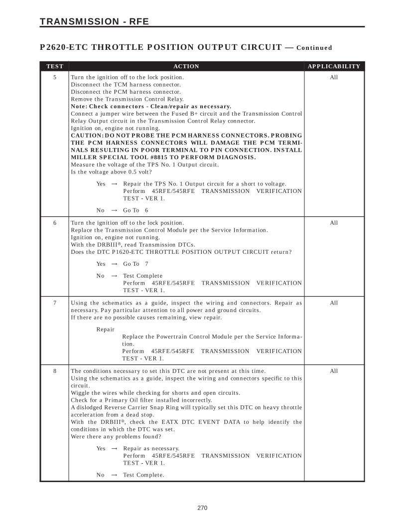
TEST ACTION APPLICABILITY
5 Turn the ignition off to the lock position.Disconnect the TCM harness connector.Disconnect the PCM harness connector.Remove the Transmission Control Relay.Note: Check connectors - Clean/repair as necessary.Connect a jumper wire between the Fused B+ circuit and the Transmission ControlRelay Output circuit in the Transmission Control Relay connector.Ignition on, engine not running.CAUTION: DO NOT PROBE THE PCM HARNESS CONNECTORS. PROBINGTHE PCM HARNESS CONNECTORS WILL DAMAGE THE PCM TERMI-NALS RESULTING IN POOR TERMINAL TO PIN CONNECTION. INSTALLMILLER SPECIAL TOOL #8815 TO PERFORM DIAGNOSIS.Measure the voltage of the TPS No. 1 Output circuit.Is the voltage above 0.5 volt?
All
Yes → Repair the TPS No. 1 Output circuit for a short to voltage.Perform 45RFE/545RFE TRANSMISSION VERIFICATIONTEST - VER 1.
No → Go To 6
6 Turn the ignition off to the lock position.Replace the Transmission Control Module per the Service Information.Ignition on, engine not running.With the DRBIIIt, read Transmission DTCs.Does the DTC P1620-ETC THROTTLE POSITION OUTPUT CIRCUIT return?
All
Yes → Go To 7
No → Test CompletePerform 45RFE/545RFE TRANSMISSION VERIFICATIONTEST - VER 1.
7 Using the schematics as a guide, inspect the wiring and connectors. Repair asnecessary. Pay particular attention to all power and ground circuits.If there are no possible causes remaining, view repair.
All
RepairReplace the Powertrain Control Module per the Service Informa-tion.Perform 45RFE/545RFE TRANSMISSION VERIFICATIONTEST - VER 1.
8 The conditions necessary to set this DTC are not present at this time.Using the schematics as a guide, inspect the wiring and connectors specific to thiscircuit.Wiggle the wires while checking for shorts and open circuits.Check for a Primary Oil filter installed incorrectly.A dislodged Reverse Carrier Snap Ring will typically set this DTC on heavy throttleacceleration from a dead stop.With the DRBIIIt, check the EATX DTC EVENT DATA to help identify theconditions in which the DTC was set.Were there any problems found?
All
Yes → Repair as necessary.Perform 45RFE/545RFE TRANSMISSION VERIFICATIONTEST - VER 1.
No → Test Complete.
270
TRANSMISSION - RFE
P2620-ETC THROTTLE POSITION OUTPUT CIRCUIT — Continued
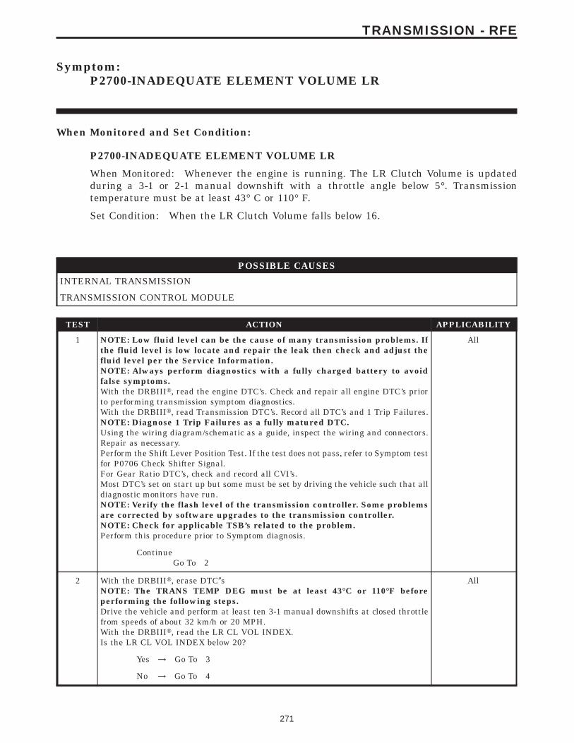
Symptom:P2700-INADEQUATE ELEMENT VOLUME LR
When Monitored and Set Condition:
P2700-INADEQUATE ELEMENT VOLUME LR
When Monitored: Whenever the engine is running. The LR Clutch Volume is updatedduring a 3-1 or 2-1 manual downshift with a throttle angle below 5°. Transmissiontemperature must be at least 43° C or 110° F.
Set Condition: When the LR Clutch Volume falls below 16.
POSSIBLE CAUSES
INTERNAL TRANSMISSION
TRANSMISSION CONTROL MODULE
TEST ACTION APPLICABILITY
1 NOTE: Low fluid level can be the cause of many transmission problems. Ifthe fluid level is low locate and repair the leak then check and adjust thefluid level per the Service Information.NOTE: Always perform diagnostics with a fully charged battery to avoidfalse symptoms.With the DRBIIIt, read the engine DTC’s. Check and repair all engine DTC’s priorto performing transmission symptom diagnostics.With the DRBIIIt, read Transmission DTC’s. Record all DTC’s and 1 Trip Failures.NOTE: Diagnose 1 Trip Failures as a fully matured DTC.Using the wiring diagram/schematic as a guide, inspect the wiring and connectors.Repair as necessary.Perform the Shift Lever Position Test. If the test does not pass, refer to Symptom testfor P0706 Check Shifter Signal.For Gear Ratio DTC’s, check and record all CVI’s.Most DTC’s set on start up but some must be set by driving the vehicle such that alldiagnostic monitors have run.NOTE: Verify the flash level of the transmission controller. Some problemsare corrected by software upgrades to the transmission controller.NOTE: Check for applicable TSB’s related to the problem.Perform this procedure prior to Symptom diagnosis.
All
ContinueGo To 2
2 With the DRBIIIt, erase DTC9sNOTE: The TRANS TEMP DEG must be at least 43°C or 110°F beforeperforming the following steps.Drive the vehicle and perform at least ten 3-1 manual downshifts at closed throttlefrom speeds of about 32 km/h or 20 MPH.With the DRBIIIt, read the LR CL VOL INDEX.Is the LR CL VOL INDEX below 20?
All
Yes → Go To 3
No → Go To 4
271
TRANSMISSION - RFE
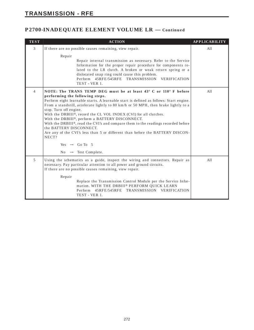
TEST ACTION APPLICABILITY
3 If there are no possible causes remaining, view repair. All
RepairRepair internal transmission as necessary. Refer to the ServiceInformation for the proper repair procedure for components re-lated to the LR clutch. A broken or weak return spring or adislocated snap ring could cause this problem.Perform 45RFE/545RFE TRANSMISSION VERIFICATIONTEST - VER 1.
4 NOTE: The TRANS TEMP DEG must be at least 43° C or 110° F beforeperforming the following steps.Perform eight learnable starts. A learnable start is defined as follows: Start engine.From a standstill, accelerate lightly to 80 km/h or 50 MPH, then brake lightly to astop. Turn off engine.With the DRBIIIt, record the CL VOL INDEX (CVI) for all clutches.With the DRBIIIt, perform a BATTERY DISCONNECT.With the DRBIIIt, read the CVI’s and compare them to the readings recorded beforethe BATTERY DISCONNECT.Are any of the CVI’s less than 5 or different than before the BATTERY DISCON-NECT?
All
Yes → Go To 5
No → Test Complete.
5 Using the schematics as a guide, inspect the wiring and connectors. Repair asnecessary. Pay particular attention to all power and ground circuits.If there are no possible causes remaining, view repair.
All
RepairReplace the Transmission Control Module per the Service Infor-mation. WITH THE DRBIIIt PERFORM QUICK LEARNPerform 45RFE/545RFE TRANSMISSION VERIFICATIONTEST - VER 1.
272
TRANSMISSION - RFE
P2700-INADEQUATE ELEMENT VOLUME LR — Continued
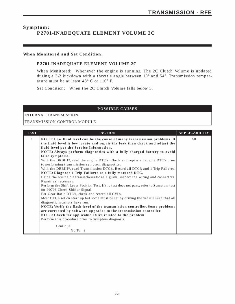
Symptom:P2701-INADEQUATE ELEMENT VOLUME 2C
When Monitored and Set Condition:
P2701-INADEQUATE ELEMENT VOLUME 2C
When Monitored: Whenever the engine is running. The 2C Clutch Volume is updatedduring a 3-2 kickdown with a throttle angle between 10° and 54°. Transmission temper-ature must be at least 43° C or 110° F.
Set Condition: When the 2C Clutch Volume falls below 5.
POSSIBLE CAUSES
INTERNAL TRANSMISSION
TRANSMISSION CONTROL MODULE
TEST ACTION APPLICABILITY
1 NOTE: Low fluid level can be the cause of many transmission problems. Ifthe fluid level is low locate and repair the leak then check and adjust thefluid level per the Service Information.NOTE: Always perform diagnostics with a fully charged battery to avoidfalse symptoms.With the DRBIIIt, read the engine DTC’s. Check and repair all engine DTC’s priorto performing transmission symptom diagnostics.With the DRBIIIt, read Transmission DTC’s. Record all DTC’s and 1 Trip Failures.NOTE: Diagnose 1 Trip Failures as a fully matured DTC.Using the wiring diagram/schematic as a guide, inspect the wiring and connectors.Repair as necessary.Perform the Shift Lever Position Test. If the test does not pass, refer to Symptom testfor P0706 Check Shifter Signal.For Gear Ratio DTC’s, check and record all CVI’s.Most DTC’s set on start up but some must be set by driving the vehicle such that alldiagnostic monitors have run.NOTE: Verify the flash level of the transmission controller. Some problemsare corrected by software upgrades to the transmission controller.NOTE: Check for applicable TSB’s related to the problem.Perform this procedure prior to Symptom diagnosis.
All
ContinueGo To 2
273
TRANSMISSION - RFE
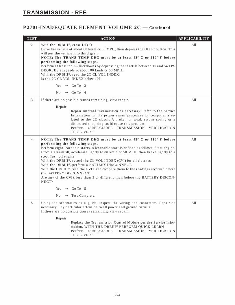
TEST ACTION APPLICABILITY
2 With the DRBIIIt, erase DTC9sDrive the vehicle at about 80 km/h or 50 MPH, then depress the OD off button. Thiswill put the vehicle into third gear.NOTE: The TRANS TEMP DEG must be at least 43° C or 110° F beforeperforming the following steps.Perform at least ten 3-2 kickdowns by depressing the throttle between 10 and 54 TPSDEGREES at speeds of about 80 km/h or 50 MPH.With the DRBIIIt, read the 2C CL VOL INDEX.Is the 2C CL VOL INDEX below 10?
All
Yes → Go To 3
No → Go To 4
3 If there are no possible causes remaining, view repair. All
RepairRepair internal transmission as necessary. Refer to the ServiceInformation for the proper repair procedure for components re-lated to the 2C clutch. A broken or weak return spring or adislocated snap ring could cause this problem.Perform 45RFE/545RFE TRANSMISSION VERIFICATIONTEST - VER 1.
4 NOTE: The TRANS TEMP DEG must be at least 43° C or 110° F beforeperforming the following steps.Perform eight learnable starts. A learnable start is defined as follows: Start engine.From a standstill, accelerate lightly to 80 km/h or 50 MPH, then brake lightly to astop. Turn off engine.With the DRBIIIt, record the CL VOL INDEX (CVI) for all clutchesWith the DRBIIIt, perform a BATTERY DISCONNECT.With the DRBIIIt, read the CVI’s and compare them to the readings recorded beforethe BATTERY DISCONNECT.Are any of the CVI’s less than 5 or different than before the BATTERY DISCON-NECT?
All
Yes → Go To 5
No → Test Complete.
5 Using the schematics as a guide, inspect the wiring and connectors. Repair asnecessary. Pay particular attention to all power and ground circuits.If there are no possible causes remaining, view repair.
All
RepairReplace the Transmission Control Module per the Service Infor-mation. WITH THE DRBIIIt PERFORM QUICK LEARNPerform 45RFE/545RFE TRANSMISSION VERIFICATIONTEST - VER 1.
274
TRANSMISSION - RFE
P2701-INADEQUATE ELEMENT VOLUME 2C — Continued
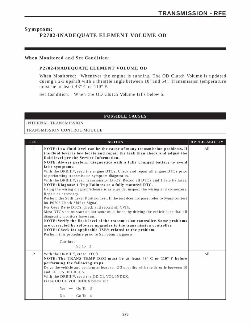
Symptom:P2702-INADEQUATE ELEMENT VOLUME OD
When Monitored and Set Condition:
P2702-INADEQUATE ELEMENT VOLUME OD
When Monitored: Whenever the engine is running. The OD Clutch Volume is updatedduring a 2-3 upshift with a throttle angle between 10° and 54°. Transmission temperaturemust be at least 43° C or 110° F.
Set Condition: When the OD Clutch Volume falls below 5.
POSSIBLE CAUSES
INTERNAL TRANSMISSION
TRANSMISSION CONTROL MODULE
TEST ACTION APPLICABILITY
1 NOTE: Low fluid level can be the cause of many transmission problems. Ifthe fluid level is low locate and repair the leak then check and adjust thefluid level per the Service Information.NOTE: Always perform diagnostics with a fully charged battery to avoidfalse symptoms.With the DRBIIIt, read the engine DTC’s. Check and repair all engine DTC’s priorto performing transmission symptom diagnostics.With the DRBIIIt, read Transmission DTC’s. Record all DTC’s and 1 Trip Failures.NOTE: Diagnose 1 Trip Failures as a fully matured DTC.Using the wiring diagram/schematic as a guide, inspect the wiring and connectors.Repair as necessary.Perform the Shift Lever Position Test. If the test does not pass, refer to Symptom testfor P0706 Check Shifter Signal.For Gear Ratio DTC’s, check and record all CVI’s.Most DTC’s set on start up but some must be set by driving the vehicle such that alldiagnostic monitors have run.NOTE: Verify the flash level of the transmission controller. Some problemsare corrected by software upgrades to the transmission controller.NOTE: Check for applicable TSB’s related to the problem.Perform this procedure prior to Symptom diagnosis.
All
ContinueGo To 2
2 With the DRBIIIt, erase DTC9sNOTE: The TRANS TEMP DEG must be at least 43° C or 110° F beforeperforming the following steps.Drive the vehicle and perform at least ten 2-3 upshifts with the throttle between 10and 54 TPS DEGREES.With the DRBIIIt, read the OD CL VOL INDEX.Is the OD CL VOL INDEX below 10?
All
Yes → Go To 3
No → Go To 4
275
TRANSMISSION - RFE

TEST ACTION APPLICABILITY
3 If there are no possible causes remaining, view repair. All
RepairRepair internal transmission as necessary. Refer to the ServiceInformation for the proper repair procedure for components re-lated to the OD clutch. A broken or weak return spring or adislocated snap ring could cause this problem.Perform 45RFE/545RFE TRANSMISSION VERIFICATIONTEST - VER 1.
4 NOTE: The TRANS TEMP DEG must be at least 43° C or 110° F beforeperforming the following steps.Perform eight learnable starts. A learnable start is defined as follows: Start engine.From a standstill, accelerate lightly to 80 km/h or 50 MPH, then brake lightly to astop. Turn off engine.With the DRBIIIt, record the CL VOL INDEX (CVI) for all clutches.With the DRBIIIt, perform a BATTERY DISCONNECT.With the DRBIIIt, read the CVI’s and compare them to the readings recorded beforethe BATTERY DISCONNECT.Are any of the CVI’s less than 5 or different than before the BATTERY DISCON-NECT?
All
Yes → Go To 5
No → Test Complete.
5 Using the schematics as a guide, inspect the wiring and connectors. Repair asnecessary. Pay particular attention to all power and ground circuits.If there are no possible causes remaining, view repair.
All
RepairReplace the Transmission Control Module per the Service Infor-mation. WITH THE DRBIIIt PERFORM QUICK LEARNPerform 45RFE/545RFE TRANSMISSION VERIFICATIONTEST - VER 1.
276
TRANSMISSION - RFE
P2702-INADEQUATE ELEMENT VOLUME OD — Continued
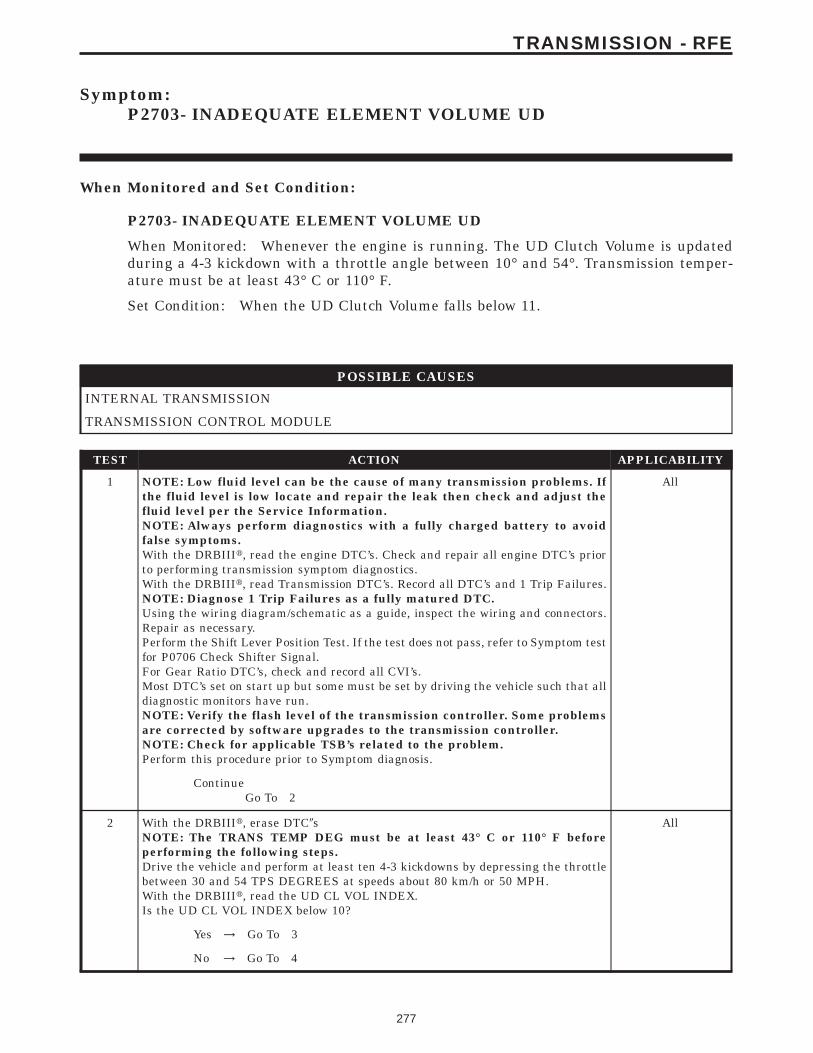
Symptom:P2703- INADEQUATE ELEMENT VOLUME UD
When Monitored and Set Condition:
P2703- INADEQUATE ELEMENT VOLUME UD
When Monitored: Whenever the engine is running. The UD Clutch Volume is updatedduring a 4-3 kickdown with a throttle angle between 10° and 54°. Transmission temper-ature must be at least 43° C or 110° F.
Set Condition: When the UD Clutch Volume falls below 11.
POSSIBLE CAUSES
INTERNAL TRANSMISSION
TRANSMISSION CONTROL MODULE
TEST ACTION APPLICABILITY
1 NOTE: Low fluid level can be the cause of many transmission problems. Ifthe fluid level is low locate and repair the leak then check and adjust thefluid level per the Service Information.NOTE: Always perform diagnostics with a fully charged battery to avoidfalse symptoms.With the DRBIIIt, read the engine DTC’s. Check and repair all engine DTC’s priorto performing transmission symptom diagnostics.With the DRBIIIt, read Transmission DTC’s. Record all DTC’s and 1 Trip Failures.NOTE: Diagnose 1 Trip Failures as a fully matured DTC.Using the wiring diagram/schematic as a guide, inspect the wiring and connectors.Repair as necessary.Perform the Shift Lever Position Test. If the test does not pass, refer to Symptom testfor P0706 Check Shifter Signal.For Gear Ratio DTC’s, check and record all CVI’s.Most DTC’s set on start up but some must be set by driving the vehicle such that alldiagnostic monitors have run.NOTE: Verify the flash level of the transmission controller. Some problemsare corrected by software upgrades to the transmission controller.NOTE: Check for applicable TSB’s related to the problem.Perform this procedure prior to Symptom diagnosis.
All
ContinueGo To 2
2 With the DRBIIIt, erase DTC9sNOTE: The TRANS TEMP DEG must be at least 43° C or 110° F beforeperforming the following steps.Drive the vehicle and perform at least ten 4-3 kickdowns by depressing the throttlebetween 30 and 54 TPS DEGREES at speeds about 80 km/h or 50 MPH.With the DRBIIIt, read the UD CL VOL INDEX.Is the UD CL VOL INDEX below 10?
All
Yes → Go To 3
No → Go To 4
277
TRANSMISSION - RFE

TEST ACTION APPLICABILITY
3 If there are no possible causes remaining, view repair. All
RepairRepair internal transmission as necessary. Refer to the ServiceInformation for the proper repair procedure for components re-lated to the UD clutch. A broken or weak return spring or adislocated snap ring could cause this problem.Perform 45RFE/545RFE TRANSMISSION VERIFICATIONTEST - VER 1.
4 NOTE: The TRANS TEMP DEG must be at least 43° C or 110° F beforeperforming the following steps.Perform eight learnable starts. A learnable start is defined as follows: Start engine.From a standstill, accelerate lightly to 80 km/h or 50 MPH, then brake lightly to astop. Turn off engine.With the DRBIIIt, record CL VOL INDEX (CVI) for all clutches.With the DRBIIIt, perform a BATTERY DISCONNECT.With the DRBIIIt, read the CVI’s and compare them to the readings recorded beforethe BATTERY DISCONNECT.Are any of the CVI’s less than 5 or different than before the BATTERY DISCON-NECT?
All
Yes → Go To 5
No → Test Complete.
5 Using the schematics as a guide, inspect the wiring and connectors. Repair asnecessary. Pay particular attention to all power and ground circuits.If there are no possible causes remaining, view repair.
All
RepairReplace the Transmission Control Module per the Service Infor-mation. WITH THE DRBIIIt PERFORM QUICK LEARNPerform 45RFE/545RFE TRANSMISSION VERIFICATIONTEST - VER 1.
278
TRANSMISSION - RFE
P2703- INADEQUATE ELEMENT VOLUME UD — Continued
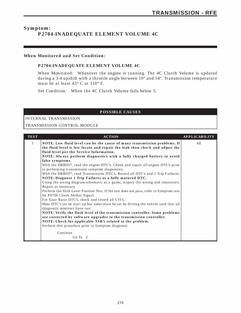
Symptom:P2704-INADEQUATE ELEMENT VOLUME 4C
When Monitored and Set Condition:
P2704-INADEQUATE ELEMENT VOLUME 4C
When Monitored: Whenever the engine is running. The 4C Clutch Volume is updatedduring a 3-4 upshift with a throttle angle between 10° and 54°. Transmission temperaturemust be at least 43° C or 110° F.
Set Condition: When the 4C Clutch Volume falls below 5.
POSSIBLE CAUSES
INTERNAL TRANSMISSION
TRANSMISSION CONTROL MODULE
TEST ACTION APPLICABILITY
1 NOTE: Low fluid level can be the cause of many transmission problems. Ifthe fluid level is low locate and repair the leak then check and adjust thefluid level per the Service Information.NOTE: Always perform diagnostics with a fully charged battery to avoidfalse symptoms.With the DRBIIIt, read the engine DTC’s. Check and repair all engine DTC’s priorto performing transmission symptom diagnostics.With the DRBIIIt, read Transmission DTC’s. Record all DTC’s and 1 Trip Failures.NOTE: Diagnose 1 Trip Failures as a fully matured DTC.Using the wiring diagram/schematic as a guide, inspect the wiring and connectors.Repair as necessary.Perform the Shift Lever Position Test. If the test does not pass, refer to Symptom testfor P0706 Check Shifter Signal.For Gear Ratio DTC’s, check and record all CVI’s.Most DTC’s set on start up but some must be set by driving the vehicle such that alldiagnostic monitors have run.NOTE: Verify the flash level of the transmission controller. Some problemsare corrected by software upgrades to the transmission controller.NOTE: Check for applicable TSB’s related to the problem.Perform this procedure prior to Symptom diagnosis.
All
ContinueGo To 2
279
TRANSMISSION - RFE
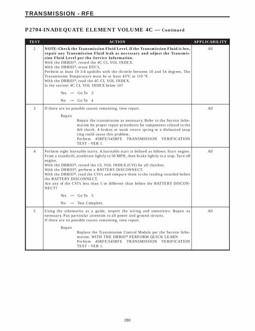
TEST ACTION APPLICABILITY
2 NOTE: Check the Transmission Fluid Level. If the Transmission Fluid is low,repair any Transmission Fluid leak as necessary and adjust the Transmis-sion Fluid Level per the Service Information.With the DRBIIIt, record the 4C CL VOL INDEX.With the DRBIIIt, erase DTC’s.Perform at least 10 3-4 upshifts with the throttle between 10 and 54 degrees. TheTransmission Temperature must be at least 43°C or 110 °F.With the DRBIIIt, read the 4C CL VOL INDEX.Is the current 4C CL VOL INDEX below 10?
All
Yes → Go To 3
No → Go To 4
3 If there are no possible causes remaining, view repair. All
RepairRepair the transmission as necessary. Refer to the Service Infor-mation for proper repair procedures for components related to the4th clutch. A broken or weak return spring or a dislocated snapring could cause this problem.Perform 45RFE/545RFE TRANSMISSION VERIFICATIONTEST - VER 1.
4 Perform eight learnable starts. A learnable start is defined as follows: Start engine.From a standstill, accelerate lightly to 50 MPH, then brake lightly to a stop. Turn offengine.With the DRBIIIt, record the CL VOL INDEX (CVI) for all clutches.With the DRBIIIt, perform a BATTERY DISCONNECT.With the DRBIIIt, read the CVI’s and compare them to the reading recorded beforethe BATTERY DISCONNECT.Are any of the CVI’s less than 5 or different than before the BATTERY DISCON-NECT?
All
Yes → Go To 5
No → Test Complete.
5 Using the schematics as a guide, inspect the wiring and connectors. Repair asnecessary. Pay particular attention to all power and ground circuits.If there are no possible causes remaining, view repair.
All
RepairReplace the Transmission Control Module per the Service Infor-mation. WITH THE DRBIIIt PERFORM QUICK LEARNPerform 45RFE/545RFE TRANSMISSION VERIFICATIONTEST - VER 1.
280
TRANSMISSION - RFE
P2704-INADEQUATE ELEMENT VOLUME 4C — Continued

Symptom:P2706-MS SOLENOID CIRCUIT
When Monitored and Set Condition:
P2706-MS SOLENOID CIRCUIT
When Monitored: Initially at power-up, then every 10 seconds thereafter. It will also betested immediately after a gear ratio or pressure switch error is detected.
Set Condition: After three consecutive solenoid continuity tests failures. After one failureif a test is run in response to a gear ratio or pressure switch error.
POSSIBLE CAUSES
RELATED RELAY DTC’S PRESENT
MS SOLENOID CONTROL CIRCUIT OPEN
TRANSMISSION CONTROL RELAY OUTPUT CIRCUIT OPEN
MS SOLENOID CONTROL CIRCUIT SHORT TO GROUND
MS SOLENOID CIRCUIT SHORT TO VOLTAGE
MS SOLENOID
TRANSMISSION CONTROL MODULE
INTERMITTENT WIRING AND CONNECTORS
TEST ACTION APPLICABILITY
1 NOTE: Low fluid level can be the cause of many transmission problems. Ifthe fluid level is low locate and repair the leak then check and adjust thefluid level per the Service Information.NOTE: Always perform diagnostics with a fully charged battery to avoidfalse symptoms.With the DRBIIIt, read the engine DTC’s. Check and repair all engine DTC’s priorto performing transmission symptom diagnostics.With the DRBIIIt, read Transmission DTC’s. Record all DTC’s and 1 Trip Failures.NOTE: Diagnose 1 Trip Failures as a fully matured DTC.Using the wiring diagram/schematic as a guide, inspect the wiring and connectors.Repair as necessary.Perform the Shift Lever Position Test. If the test does not pass, refer to Symptom testfor P0706 Check Shifter Signal.For Gear Ratio DTC’s, check and record all CVI’s.Most DTC’s set on start up but some must be set by driving the vehicle such that alldiagnostic monitors have run.NOTE: Verify the flash level of the transmission controller. Some problemsare corrected by software upgrades to the transmission controller.NOTE: Check for applicable TSB’s related to the problem.Perform this procedure prior to Symptom diagnosis.
All
ContinueGo To 2
281
TRANSMISSION - RFE
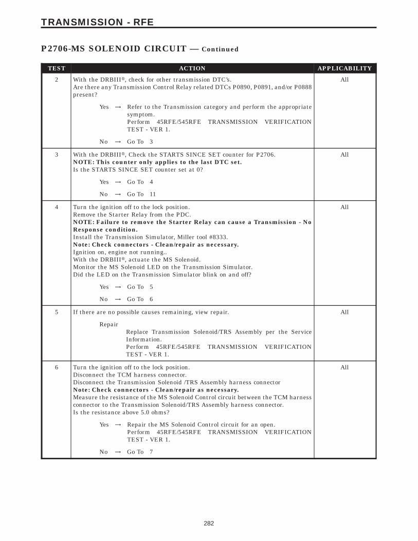
TEST ACTION APPLICABILITY
2 With the DRBIIIt, check for other transmission DTC’s.Are there any Transmission Control Relay related DTCs P0890, P0891, and/or P0888present?
All
Yes → Refer to the Transmission category and perform the appropriatesymptom.Perform 45RFE/545RFE TRANSMISSION VERIFICATIONTEST - VER 1.
No → Go To 3
3 With the DRBIIIt, Check the STARTS SINCE SET counter for P2706.NOTE: This counter only applies to the last DTC set.Is the STARTS SINCE SET counter set at 0?
All
Yes → Go To 4
No → Go To 11
4 Turn the ignition off to the lock position.Remove the Starter Relay from the PDC.NOTE: Failure to remove the Starter Relay can cause a Transmission - NoResponse condition.Install the Transmission Simulator, Miller tool #8333.Note: Check connectors - Clean/repair as necessary.Ignition on, engine not running..With the DRBIIIt, actuate the MS Solenoid.Monitor the MS Solenoid LED on the Transmission Simulator.Did the LED on the Transmission Simulator blink on and off?
All
Yes → Go To 5
No → Go To 6
5 If there are no possible causes remaining, view repair. All
RepairReplace Transmission Solenoid/TRS Assembly per the ServiceInformation.Perform 45RFE/545RFE TRANSMISSION VERIFICATIONTEST - VER 1.
6 Turn the ignition off to the lock position.Disconnect the TCM harness connector.Disconnect the Transmission Solenoid /TRS Assembly harness connectorNote: Check connectors - Clean/repair as necessary.Measure the resistance of the MS Solenoid Control circuit between the TCM harnessconnector to the Transmission Solenoid/TRS Assembly harness connector.Is the resistance above 5.0 ohms?
All
Yes → Repair the MS Solenoid Control circuit for an open.Perform 45RFE/545RFE TRANSMISSION VERIFICATIONTEST - VER 1.
No → Go To 7
282
TRANSMISSION - RFE
P2706-MS SOLENOID CIRCUIT — Continued
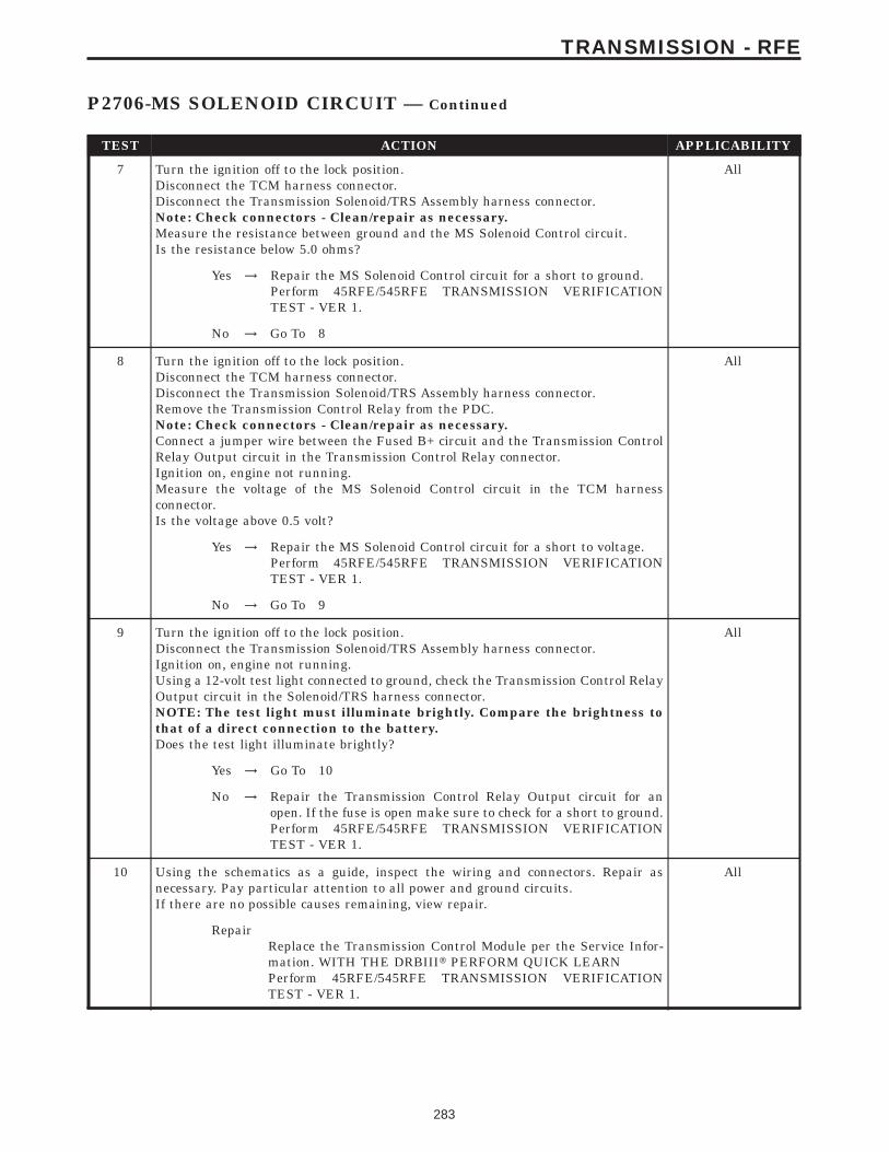
TEST ACTION APPLICABILITY
7 Turn the ignition off to the lock position.Disconnect the TCM harness connector.Disconnect the Transmission Solenoid/TRS Assembly harness connector.Note: Check connectors - Clean/repair as necessary.Measure the resistance between ground and the MS Solenoid Control circuit.Is the resistance below 5.0 ohms?
All
Yes → Repair the MS Solenoid Control circuit for a short to ground.Perform 45RFE/545RFE TRANSMISSION VERIFICATIONTEST - VER 1.
No → Go To 8
8 Turn the ignition off to the lock position.Disconnect the TCM harness connector.Disconnect the Transmission Solenoid/TRS Assembly harness connector.Remove the Transmission Control Relay from the PDC.Note: Check connectors - Clean/repair as necessary.Connect a jumper wire between the Fused B+ circuit and the Transmission ControlRelay Output circuit in the Transmission Control Relay connector.Ignition on, engine not running.Measure the voltage of the MS Solenoid Control circuit in the TCM harnessconnector.Is the voltage above 0.5 volt?
All
Yes → Repair the MS Solenoid Control circuit for a short to voltage.Perform 45RFE/545RFE TRANSMISSION VERIFICATIONTEST - VER 1.
No → Go To 9
9 Turn the ignition off to the lock position.Disconnect the Transmission Solenoid/TRS Assembly harness connector.Ignition on, engine not running.Using a 12-volt test light connected to ground, check the Transmission Control RelayOutput circuit in the Solenoid/TRS harness connector.NOTE: The test light must illuminate brightly. Compare the brightness tothat of a direct connection to the battery.Does the test light illuminate brightly?
All
Yes → Go To 10
No → Repair the Transmission Control Relay Output circuit for anopen. If the fuse is open make sure to check for a short to ground.Perform 45RFE/545RFE TRANSMISSION VERIFICATIONTEST - VER 1.
10 Using the schematics as a guide, inspect the wiring and connectors. Repair asnecessary. Pay particular attention to all power and ground circuits.If there are no possible causes remaining, view repair.
All
RepairReplace the Transmission Control Module per the Service Infor-mation. WITH THE DRBIIIt PERFORM QUICK LEARNPerform 45RFE/545RFE TRANSMISSION VERIFICATIONTEST - VER 1.
283
TRANSMISSION - RFE
P2706-MS SOLENOID CIRCUIT — Continued
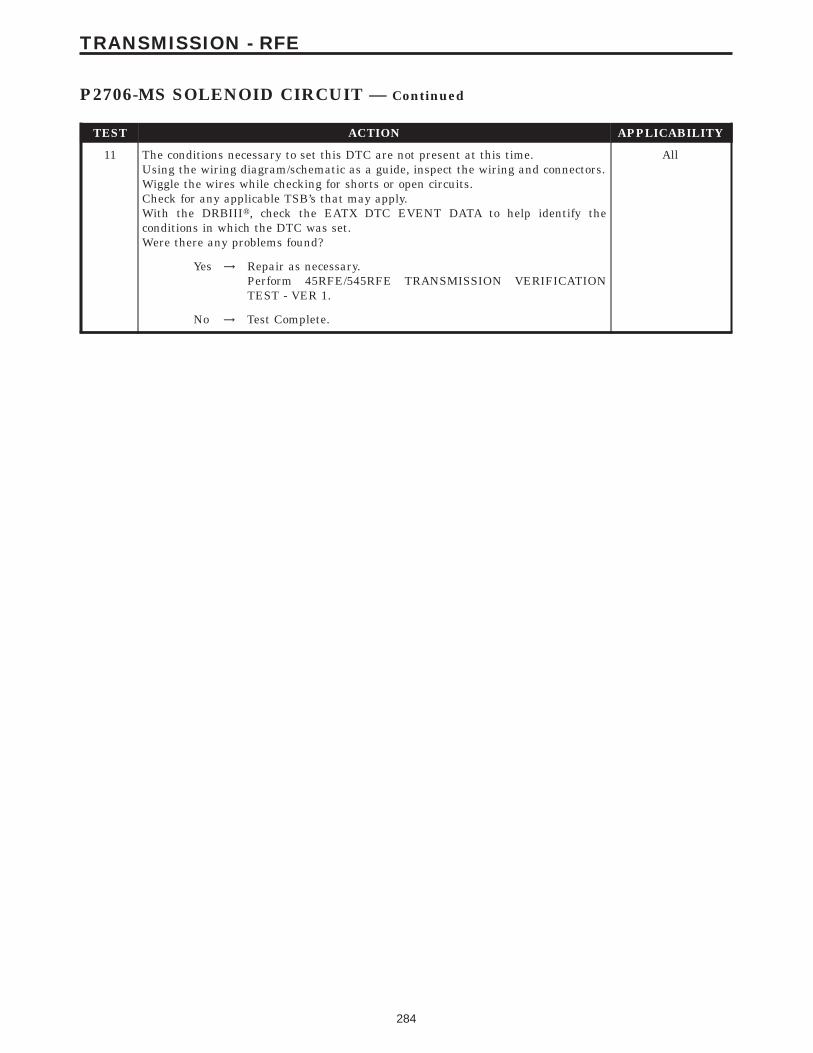
TEST ACTION APPLICABILITY
11 The conditions necessary to set this DTC are not present at this time.Using the wiring diagram/schematic as a guide, inspect the wiring and connectors.Wiggle the wires while checking for shorts or open circuits.Check for any applicable TSB’s that may apply.With the DRBIIIt, check the EATX DTC EVENT DATA to help identify theconditions in which the DTC was set.Were there any problems found?
All
Yes → Repair as necessary.Perform 45RFE/545RFE TRANSMISSION VERIFICATIONTEST - VER 1.
No → Test Complete.
284
TRANSMISSION - RFE
P2706-MS SOLENOID CIRCUIT — Continued
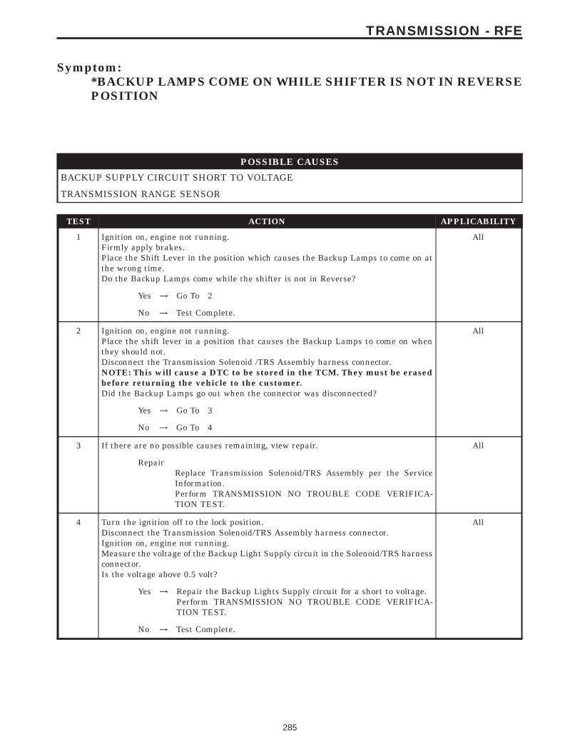
Symptom:*BACKUP LAMPS COME ON WHILE SHIFTER IS NOT IN REVERSEPOSITION
POSSIBLE CAUSES
BACKUP SUPPLY CIRCUIT SHORT TO VOLTAGE
TRANSMISSION RANGE SENSOR
TEST ACTION APPLICABILITY
1 Ignition on, engine not running.Firmly apply brakes.Place the Shift Lever in the position which causes the Backup Lamps to come on atthe wrong time.Do the Backup Lamps come while the shifter is not in Reverse?
All
Yes → Go To 2
No → Test Complete.
2 Ignition on, engine not running.Place the shift lever in a position that causes the Backup Lamps to come on whenthey should not.Disconnect the Transmission Solenoid /TRS Assembly harness connector.NOTE: This will cause a DTC to be stored in the TCM. They must be erasedbefore returning the vehicle to the customer.Did the Backup Lamps go out when the connector was disconnected?
All
Yes → Go To 3
No → Go To 4
3 If there are no possible causes remaining, view repair. All
RepairReplace Transmission Solenoid/TRS Assembly per the ServiceInformation.Perform TRANSMISSION NO TROUBLE CODE VERIFICA-TION TEST.
4 Turn the ignition off to the lock position.Disconnect the Transmission Solenoid/TRS Assembly harness connector.Ignition on, engine not running.Measure the voltage of the Backup Light Supply circuit in the Solenoid/TRS harnessconnector.Is the voltage above 0.5 volt?
All
Yes → Repair the Backup Lights Supply circuit for a short to voltage.Perform TRANSMISSION NO TROUBLE CODE VERIFICA-TION TEST.
No → Test Complete.
285
TRANSMISSION - RFE
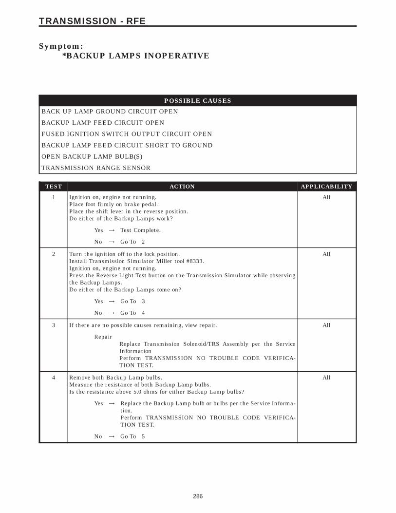
Symptom:*BACKUP LAMPS INOPERATIVE
POSSIBLE CAUSES
BACK UP LAMP GROUND CIRCUIT OPEN
BACKUP LAMP FEED CIRCUIT OPEN
FUSED IGNITION SWITCH OUTPUT CIRCUIT OPEN
BACKUP LAMP FEED CIRCUIT SHORT TO GROUND
OPEN BACKUP LAMP BULB(S)
TRANSMISSION RANGE SENSOR
TEST ACTION APPLICABILITY
1 Ignition on, engine not running.Place foot firmly on brake pedal.Place the shift lever in the reverse position.Do either of the Backup Lamps work?
All
Yes → Test Complete.
No → Go To 2
2 Turn the ignition off to the lock position.Install Transmission Simulator Miller tool #8333.Ignition on, engine not running.Press the Reverse Light Test button on the Transmission Simulator while observingthe Backup Lamps.Do either of the Backup Lamps come on?
All
Yes → Go To 3
No → Go To 4
3 If there are no possible causes remaining, view repair. All
RepairReplace Transmission Solenoid/TRS Assembly per the ServiceInformationPerform TRANSMISSION NO TROUBLE CODE VERIFICA-TION TEST.
4 Remove both Backup Lamp bulbs.Measure the resistance of both Backup Lamp bulbs.Is the resistance above 5.0 ohms for either Backup Lamp bulbs?
All
Yes → Replace the Backup Lamp bulb or bulbs per the Service Informa-tion.Perform TRANSMISSION NO TROUBLE CODE VERIFICA-TION TEST.
No → Go To 5
286
TRANSMISSION - RFE
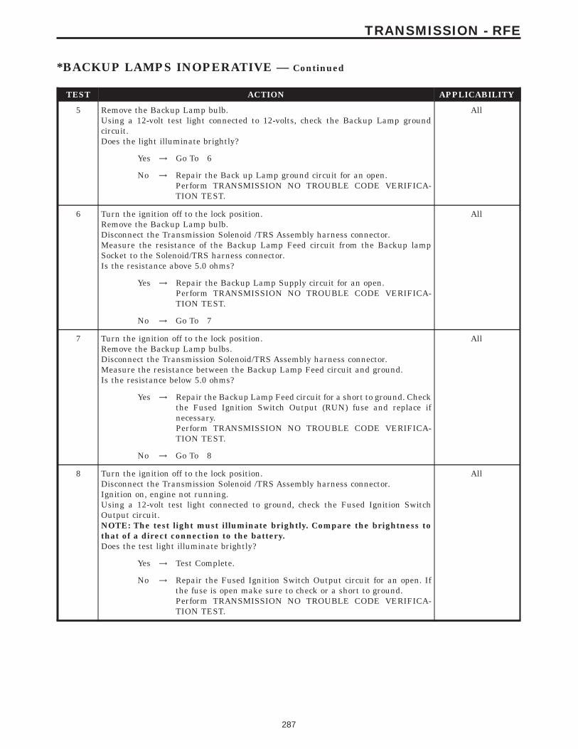
TEST ACTION APPLICABILITY
5 Remove the Backup Lamp bulb.Using a 12-volt test light connected to 12-volts, check the Backup Lamp groundcircuit.Does the light illuminate brightly?
All
Yes → Go To 6
No → Repair the Back up Lamp ground circuit for an open.Perform TRANSMISSION NO TROUBLE CODE VERIFICA-TION TEST.
6 Turn the ignition off to the lock position.Remove the Backup Lamp bulb.Disconnect the Transmission Solenoid /TRS Assembly harness connector.Measure the resistance of the Backup Lamp Feed circuit from the Backup lampSocket to the Solenoid/TRS harness connector.Is the resistance above 5.0 ohms?
All
Yes → Repair the Backup Lamp Supply circuit for an open.Perform TRANSMISSION NO TROUBLE CODE VERIFICA-TION TEST.
No → Go To 7
7 Turn the ignition off to the lock position.Remove the Backup Lamp bulbs.Disconnect the Transmission Solenoid/TRS Assembly harness connector.Measure the resistance between the Backup Lamp Feed circuit and ground.Is the resistance below 5.0 ohms?
All
Yes → Repair the Backup Lamp Feed circuit for a short to ground. Checkthe Fused Ignition Switch Output (RUN) fuse and replace ifnecessary.Perform TRANSMISSION NO TROUBLE CODE VERIFICA-TION TEST.
No → Go To 8
8 Turn the ignition off to the lock position.Disconnect the Transmission Solenoid /TRS Assembly harness connector.Ignition on, engine not running.Using a 12-volt test light connected to ground, check the Fused Ignition SwitchOutput circuit.NOTE: The test light must illuminate brightly. Compare the brightness tothat of a direct connection to the battery.Does the test light illuminate brightly?
All
Yes → Test Complete.
No → Repair the Fused Ignition Switch Output circuit for an open. Ifthe fuse is open make sure to check or a short to ground.Perform TRANSMISSION NO TROUBLE CODE VERIFICA-TION TEST.
287
TRANSMISSION - RFE
*BACKUP LAMPS INOPERATIVE — Continued
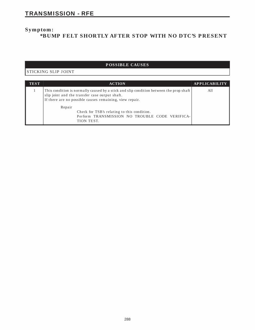
Symptom:*BUMP FELT SHORTLY AFTER STOP WITH NO DTC’S PRESENT
POSSIBLE CAUSES
STICKING SLIP JOINT
TEST ACTION APPLICABILITY
1 This condition is normally caused by a stick and slip condition between the prop shaftslip joint and the transfer case output shaft.If there are no possible causes remaining, view repair.
All
RepairCheck for TSB’s relating to this condition.Perform TRANSMISSION NO TROUBLE CODE VERIFICA-TION TEST.
288
TRANSMISSION - RFE
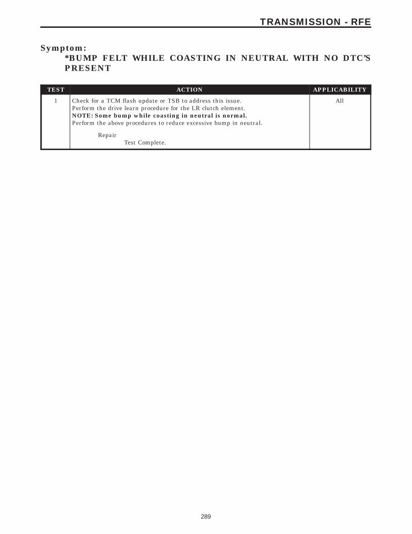
Symptom:*BUMP FELT WHILE COASTING IN NEUTRAL WITH NO DTC’SPRESENT
TEST ACTION APPLICABILITY
1 Check for a TCM flash update or TSB to address this issue.Perform the drive learn procedure for the LR clutch element.NOTE: Some bump while coasting in neutral is normal.Perform the above procedures to reduce excessive bump in neutral.
All
RepairTest Complete.
289
TRANSMISSION - RFE
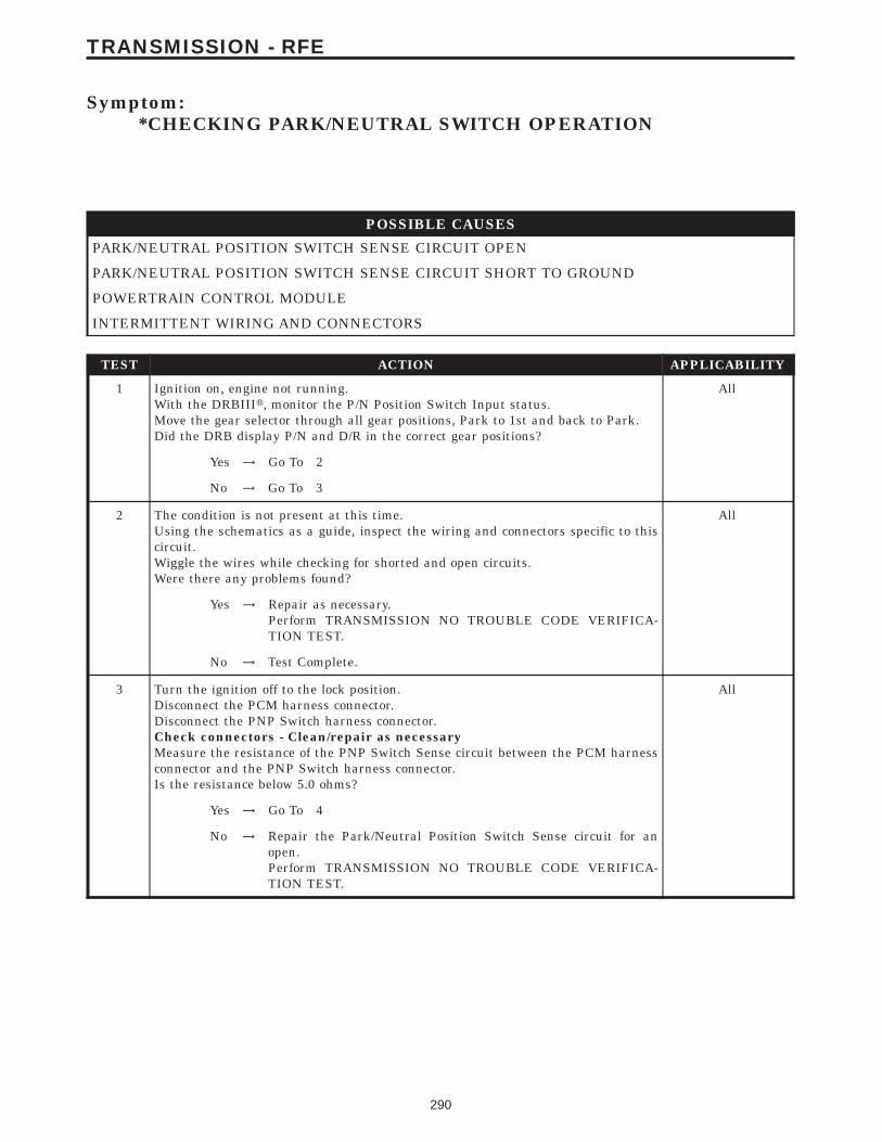
Symptom:*CHECKING PARK/NEUTRAL SWITCH OPERATION
POSSIBLE CAUSES
PARK/NEUTRAL POSITION SWITCH SENSE CIRCUIT OPEN
PARK/NEUTRAL POSITION SWITCH SENSE CIRCUIT SHORT TO GROUND
POWERTRAIN CONTROL MODULE
INTERMITTENT WIRING AND CONNECTORS
TEST ACTION APPLICABILITY
1 Ignition on, engine not running.With the DRBIIIt, monitor the P/N Position Switch Input status.Move the gear selector through all gear positions, Park to 1st and back to Park.Did the DRB display P/N and D/R in the correct gear positions?
All
Yes → Go To 2
No → Go To 3
2 The condition is not present at this time.Using the schematics as a guide, inspect the wiring and connectors specific to thiscircuit.Wiggle the wires while checking for shorted and open circuits.Were there any problems found?
All
Yes → Repair as necessary.Perform TRANSMISSION NO TROUBLE CODE VERIFICA-TION TEST.
No → Test Complete.
3 Turn the ignition off to the lock position.Disconnect the PCM harness connector.Disconnect the PNP Switch harness connector.Check connectors - Clean/repair as necessaryMeasure the resistance of the PNP Switch Sense circuit between the PCM harnessconnector and the PNP Switch harness connector.Is the resistance below 5.0 ohms?
All
Yes → Go To 4
No → Repair the Park/Neutral Position Switch Sense circuit for anopen.Perform TRANSMISSION NO TROUBLE CODE VERIFICA-TION TEST.
290
TRANSMISSION - RFE
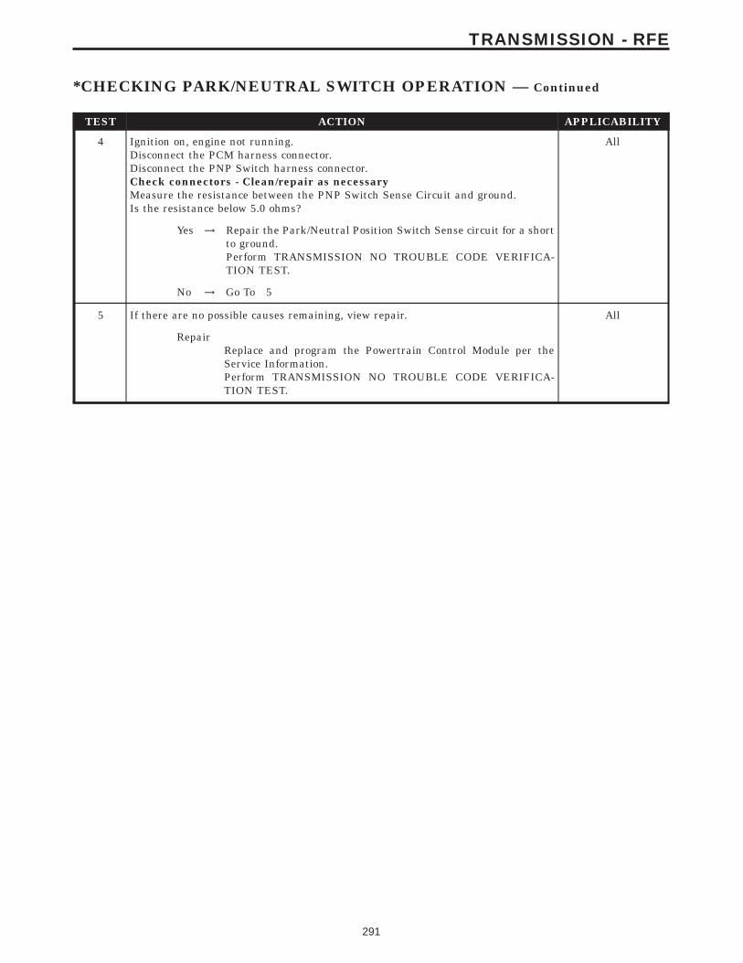
TEST ACTION APPLICABILITY
4 Ignition on, engine not running.Disconnect the PCM harness connector.Disconnect the PNP Switch harness connector.Check connectors - Clean/repair as necessaryMeasure the resistance between the PNP Switch Sense Circuit and ground.Is the resistance below 5.0 ohms?
All
Yes → Repair the Park/Neutral Position Switch Sense circuit for a shortto ground.Perform TRANSMISSION NO TROUBLE CODE VERIFICA-TION TEST.
No → Go To 5
5 If there are no possible causes remaining, view repair. All
RepairReplace and program the Powertrain Control Module per theService Information.Perform TRANSMISSION NO TROUBLE CODE VERIFICA-TION TEST.
291
TRANSMISSION - RFE
*CHECKING PARK/NEUTRAL SWITCH OPERATION — Continued
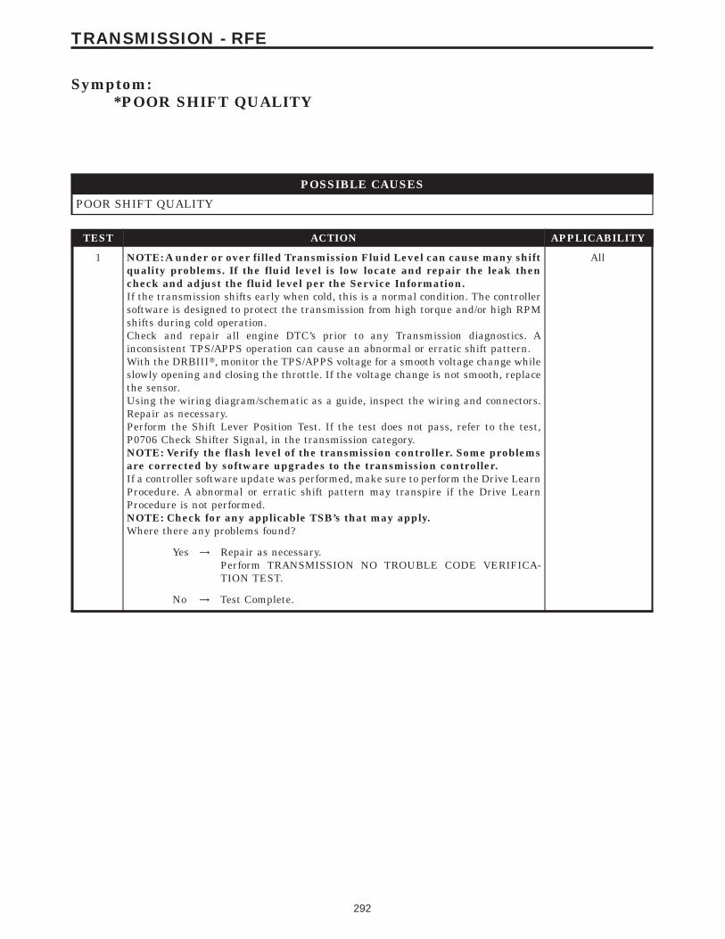
Symptom:*POOR SHIFT QUALITY
POSSIBLE CAUSES
POOR SHIFT QUALITY
TEST ACTION APPLICABILITY
1 NOTE: A under or over filled Transmission Fluid Level can cause many shiftquality problems. If the fluid level is low locate and repair the leak thencheck and adjust the fluid level per the Service Information.If the transmission shifts early when cold, this is a normal condition. The controllersoftware is designed to protect the transmission from high torque and/or high RPMshifts during cold operation.Check and repair all engine DTC’s prior to any Transmission diagnostics. Ainconsistent TPS/APPS operation can cause an abnormal or erratic shift pattern.With the DRBIIIt, monitor the TPS/APPS voltage for a smooth voltage change whileslowly opening and closing the throttle. If the voltage change is not smooth, replacethe sensor.Using the wiring diagram/schematic as a guide, inspect the wiring and connectors.Repair as necessary.Perform the Shift Lever Position Test. If the test does not pass, refer to the test,P0706 Check Shifter Signal, in the transmission category.NOTE: Verify the flash level of the transmission controller. Some problemsare corrected by software upgrades to the transmission controller.If a controller software update was performed, make sure to perform the Drive LearnProcedure. A abnormal or erratic shift pattern may transpire if the Drive LearnProcedure is not performed.NOTE: Check for any applicable TSB’s that may apply.Where there any problems found?
All
Yes → Repair as necessary.Perform TRANSMISSION NO TROUBLE CODE VERIFICA-TION TEST.
No → Test Complete.
292
TRANSMISSION - RFE
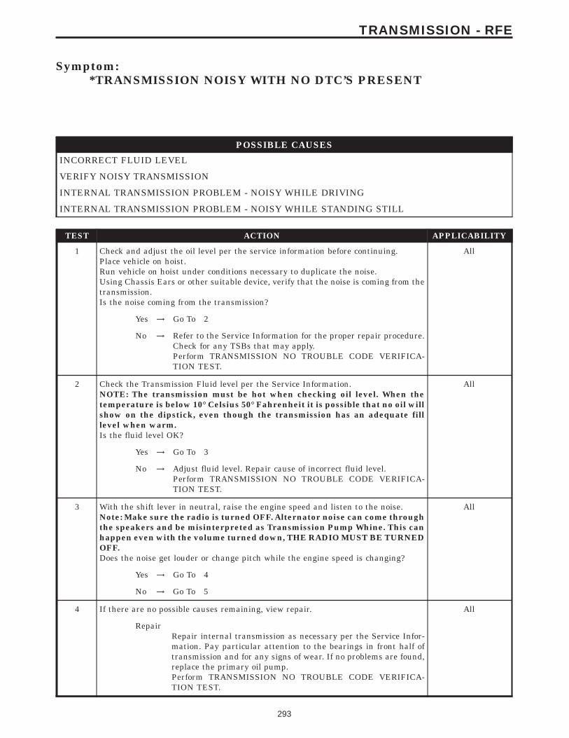
Symptom:*TRANSMISSION NOISY WITH NO DTC’S PRESENT
POSSIBLE CAUSES
INCORRECT FLUID LEVEL
VERIFY NOISY TRANSMISSION
INTERNAL TRANSMISSION PROBLEM - NOISY WHILE DRIVING
INTERNAL TRANSMISSION PROBLEM - NOISY WHILE STANDING STILL
TEST ACTION APPLICABILITY
1 Check and adjust the oil level per the service information before continuing.Place vehicle on hoist.Run vehicle on hoist under conditions necessary to duplicate the noise.Using Chassis Ears or other suitable device, verify that the noise is coming from thetransmission.Is the noise coming from the transmission?
All
Yes → Go To 2
No → Refer to the Service Information for the proper repair procedure.Check for any TSBs that may apply.Perform TRANSMISSION NO TROUBLE CODE VERIFICA-TION TEST.
2 Check the Transmission Fluid level per the Service Information.NOTE: The transmission must be hot when checking oil level. When thetemperature is below 10° Celsius 50° Fahrenheit it is possible that no oil willshow on the dipstick, even though the transmission has an adequate filllevel when warm.Is the fluid level OK?
All
Yes → Go To 3
No → Adjust fluid level. Repair cause of incorrect fluid level.Perform TRANSMISSION NO TROUBLE CODE VERIFICA-TION TEST.
3 With the shift lever in neutral, raise the engine speed and listen to the noise.Note: Make sure the radio is turned OFF. Alternator noise can come throughthe speakers and be misinterpreted as Transmission Pump Whine. This canhappen even with the volume turned down, THE RADIO MUST BE TURNEDOFF.Does the noise get louder or change pitch while the engine speed is changing?
All
Yes → Go To 4
No → Go To 5
4 If there are no possible causes remaining, view repair. All
RepairRepair internal transmission as necessary per the Service Infor-mation. Pay particular attention to the bearings in front half oftransmission and for any signs of wear. If no problems are found,replace the primary oil pump.Perform TRANSMISSION NO TROUBLE CODE VERIFICA-TION TEST.
293
TRANSMISSION - RFE
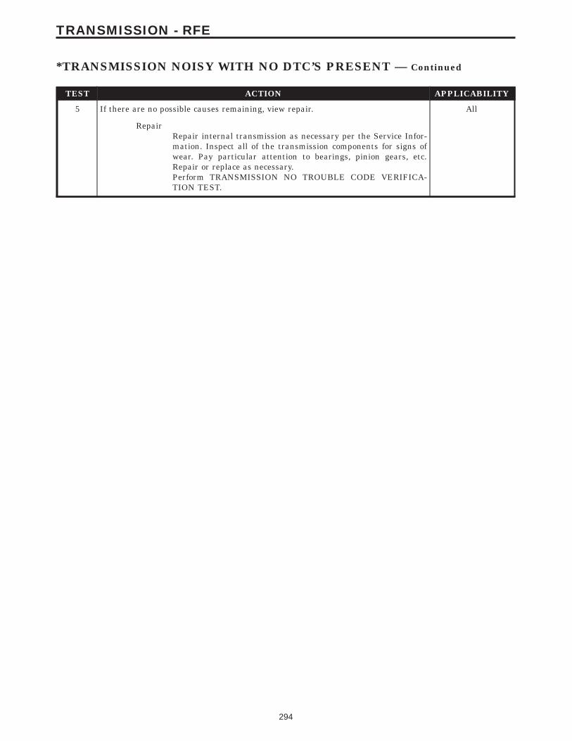
TEST ACTION APPLICABILITY
5 If there are no possible causes remaining, view repair. All
RepairRepair internal transmission as necessary per the Service Infor-mation. Inspect all of the transmission components for signs ofwear. Pay particular attention to bearings, pinion gears, etc.Repair or replace as necessary.Perform TRANSMISSION NO TROUBLE CODE VERIFICA-TION TEST.
294
TRANSMISSION - RFE
*TRANSMISSION NOISY WITH NO DTC’S PRESENT — Continued
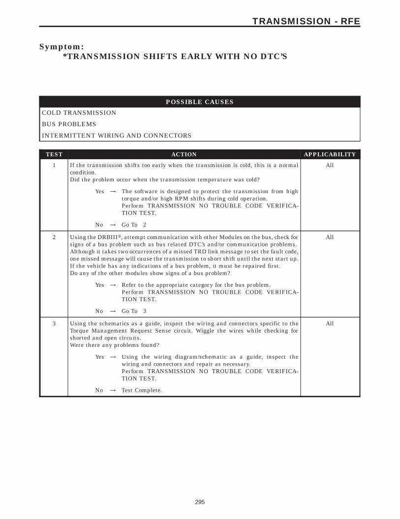
Symptom:*TRANSMISSION SHIFTS EARLY WITH NO DTC’S
POSSIBLE CAUSES
COLD TRANSMISSION
BUS PROBLEMS
INTERMITTENT WIRING AND CONNECTORS
TEST ACTION APPLICABILITY
1 If the transmission shifts too early when the transmission is cold, this is a normalcondition.Did the problem occur when the transmission temperature was cold?
All
Yes → The software is designed to protect the transmission from hightorque and/or high RPM shifts during cold operation.Perform TRANSMISSION NO TROUBLE CODE VERIFICA-TION TEST.
No → Go To 2
2 Using the DRBIIIt, attempt communication with other Modules on the bus, check forsigns of a bus problem such as bus related DTC’s and/or communication problems.Although it takes two occurrences of a missed TRD link message to set the fault code,one missed message will cause the transmission to short shift until the next start up.If the vehicle has any indications of a bus problem, it must be repaired first.Do any of the other modules show signs of a bus problem?
All
Yes → Refer to the appropriate category for the bus problem.Perform TRANSMISSION NO TROUBLE CODE VERIFICA-TION TEST.
No → Go To 3
3 Using the schematics as a guide, inspect the wiring and connectors specific to theTorque Management Request Sense circuit. Wiggle the wires while checking forshorted and open circuits.Were there any problems found?
All
Yes → Using the wiring diagram/schematic as a guide, inspect thewiring and connectors and repair as necessary.Perform TRANSMISSION NO TROUBLE CODE VERIFICA-TION TEST.
No → Test Complete.
295
TRANSMISSION - RFE
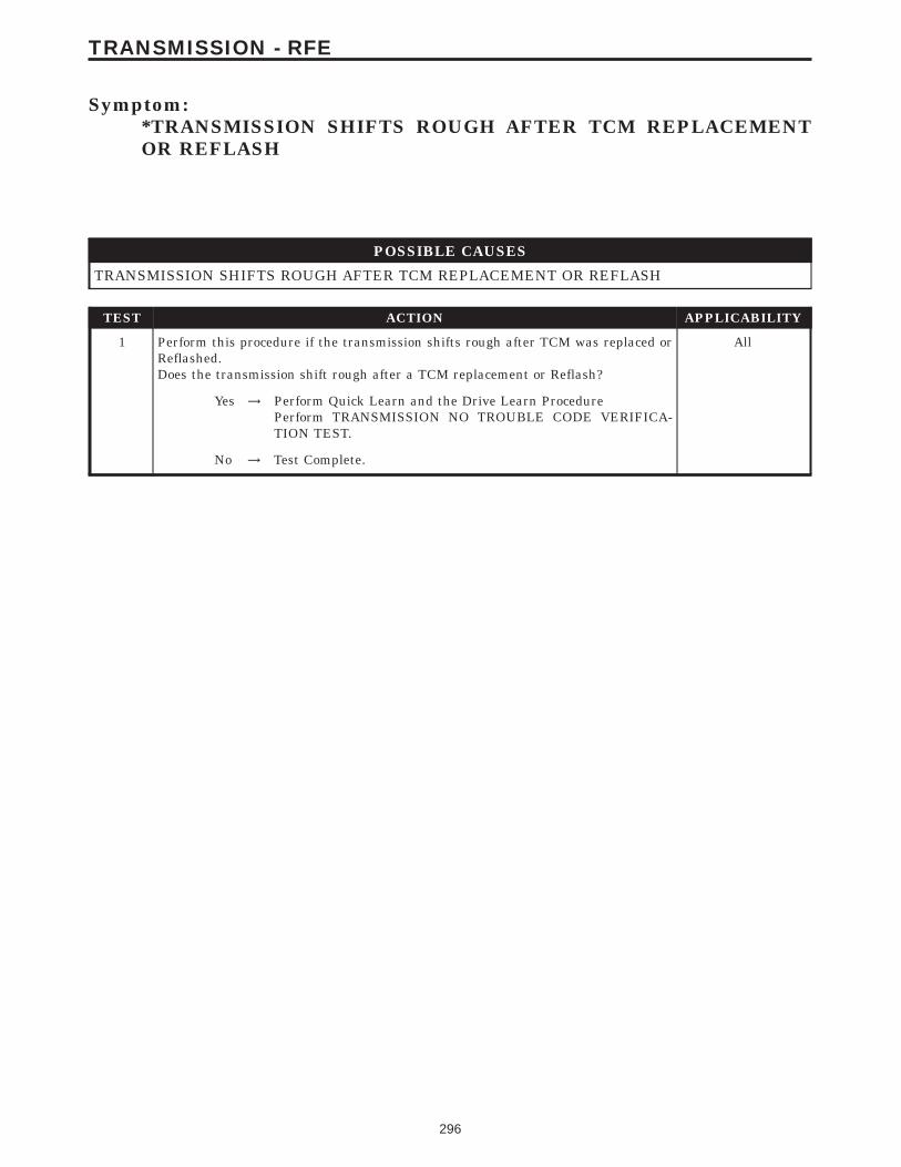
Symptom:*TRANSMISSION SHIFTS ROUGH AFTER TCM REPLACEMENTOR REFLASH
POSSIBLE CAUSES
TRANSMISSION SHIFTS ROUGH AFTER TCM REPLACEMENT OR REFLASH
TEST ACTION APPLICABILITY
1 Perform this procedure if the transmission shifts rough after TCM was replaced orReflashed.Does the transmission shift rough after a TCM replacement or Reflash?
All
Yes → Perform Quick Learn and the Drive Learn ProcedurePerform TRANSMISSION NO TROUBLE CODE VERIFICA-TION TEST.
No → Test Complete.
296
TRANSMISSION - RFE
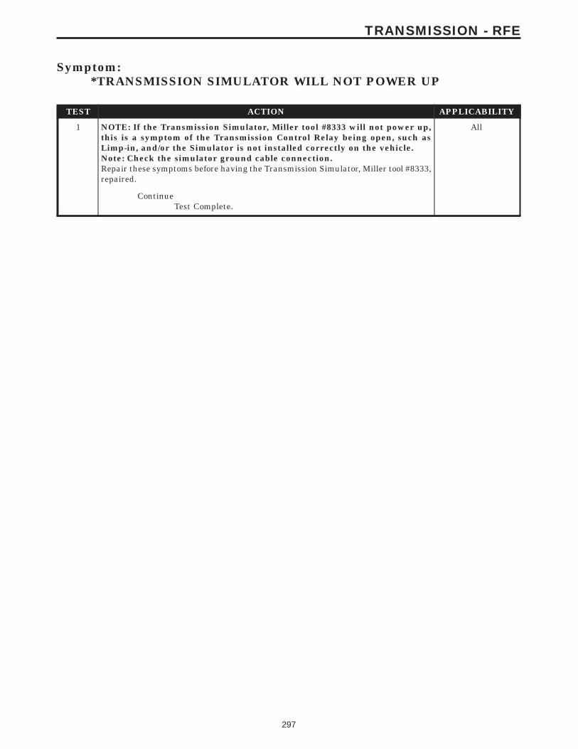
Symptom:*TRANSMISSION SIMULATOR WILL NOT POWER UP
TEST ACTION APPLICABILITY
1 NOTE: If the Transmission Simulator, Miller tool #8333 will not power up,this is a symptom of the Transmission Control Relay being open, such asLimp-in, and/or the Simulator is not installed correctly on the vehicle.Note: Check the simulator ground cable connection.Repair these symptoms before having the Transmission Simulator, Miller tool #8333,repaired.
All
ContinueTest Complete.
297
TRANSMISSION - RFE
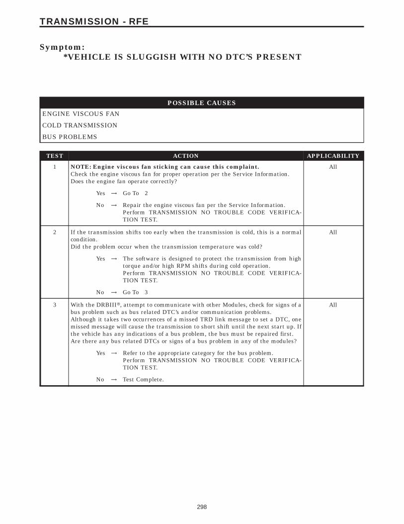
Symptom:*VEHICLE IS SLUGGISH WITH NO DTC’S PRESENT
POSSIBLE CAUSES
ENGINE VISCOUS FAN
COLD TRANSMISSION
BUS PROBLEMS
TEST ACTION APPLICABILITY
1 NOTE: Engine viscous fan sticking can cause this complaint.Check the engine viscous fan for proper operation per the Service Information.Does the engine fan operate correctly?
All
Yes → Go To 2
No → Repair the engine viscous fan per the Service Information.Perform TRANSMISSION NO TROUBLE CODE VERIFICA-TION TEST.
2 If the transmission shifts too early when the transmission is cold, this is a normalcondition.Did the problem occur when the transmission temperature was cold?
All
Yes → The software is designed to protect the transmission from hightorque and/or high RPM shifts during cold operation.Perform TRANSMISSION NO TROUBLE CODE VERIFICA-TION TEST.
No → Go To 3
3 With the DRBIIIt, attempt to communicate with other Modules, check for signs of abus problem such as bus related DTC’s and/or communication problems.Although it takes two occurrences of a missed TRD link message to set a DTC, onemissed message will cause the transmission to short shift until the next start up. Ifthe vehicle has any indications of a bus problem, the bus must be repaired first.Are there any bus related DTCs or signs of a bus problem in any of the modules?
All
Yes → Refer to the appropriate category for the bus problem.Perform TRANSMISSION NO TROUBLE CODE VERIFICA-TION TEST.
No → Test Complete.
298
TRANSMISSION - RFE
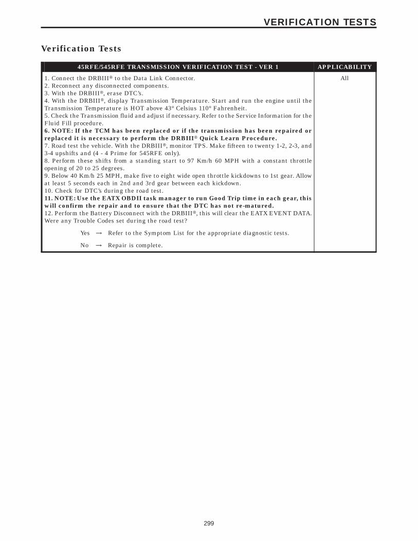
Verification Tests
45RFE/545RFE TRANSMISSION VERIFICATION TEST - VER 1 APPLICABILITY
1. Connect the DRBIIIt to the Data Link Connector.2. Reconnect any disconnected components.3. With the DRBIIIt, erase DTC’s.4. With the DRBIIIt, display Transmission Temperature. Start and run the engine until theTransmission Temperature is HOT above 43° Celsius 110° Fahrenheit.5. Check the Transmission fluid and adjust if necessary. Refer to the Service Information for theFluid Fill procedure.6. NOTE: If the TCM has been replaced or if the transmission has been repaired orreplaced it is necessary to perform the DRBIIIt Quick Learn Procedure.7. Road test the vehicle. With the DRBIIIt, monitor TPS. Make fifteen to twenty 1-2, 2-3, and3-4 upshifts and (4 - 4 Prime for 545RFE only).8. Perform these shifts from a standing start to 97 Km/h 60 MPH with a constant throttleopening of 20 to 25 degrees.9. Below 40 Km/h 25 MPH, make five to eight wide open throttle kickdowns to 1st gear. Allowat least 5 seconds each in 2nd and 3rd gear between each kickdown.10. Check for DTC’s during the road test.11. NOTE: Use the EATX OBDII task manager to run Good Trip time in each gear, thiswill confirm the repair and to ensure that the DTC has not re-matured.12. Perform the Battery Disconnect with the DRBIIIt, this will clear the EATX EVENT DATA.Were any Trouble Codes set during the road test?
All
Yes → Refer to the Symptom List for the appropriate diagnostic tests.
No → Repair is complete.
299
VERIFICATION TESTS
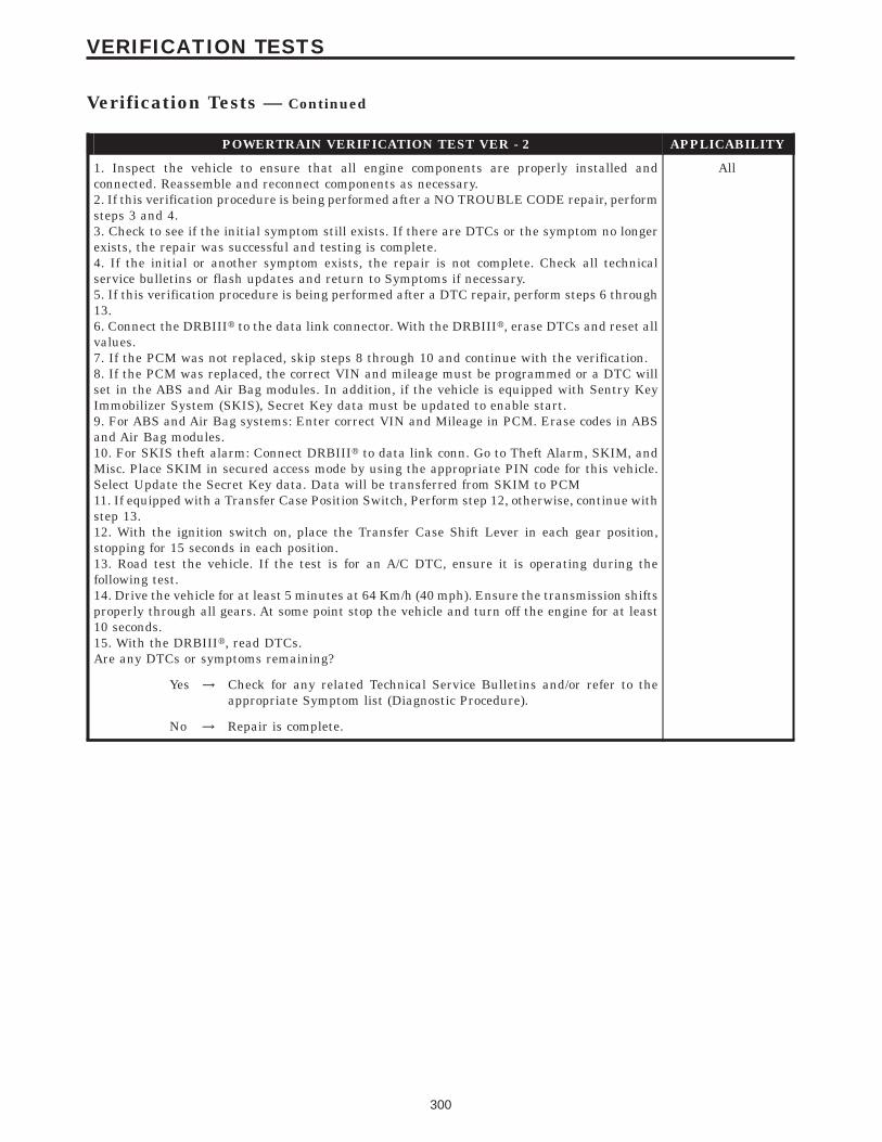
POWERTRAIN VERIFICATION TEST VER - 2 APPLICABILITY
1. Inspect the vehicle to ensure that all engine components are properly installed andconnected. Reassemble and reconnect components as necessary.2. If this verification procedure is being performed after a NO TROUBLE CODE repair, performsteps 3 and 4.3. Check to see if the initial symptom still exists. If there are DTCs or the symptom no longerexists, the repair was successful and testing is complete.4. If the initial or another symptom exists, the repair is not complete. Check all technicalservice bulletins or flash updates and return to Symptoms if necessary.5. If this verification procedure is being performed after a DTC repair, perform steps 6 through13.6. Connect the DRBIIIt to the data link connector. With the DRBIIIt, erase DTCs and reset allvalues.7. If the PCM was not replaced, skip steps 8 through 10 and continue with the verification.8. If the PCM was replaced, the correct VIN and mileage must be programmed or a DTC willset in the ABS and Air Bag modules. In addition, if the vehicle is equipped with Sentry KeyImmobilizer System (SKIS), Secret Key data must be updated to enable start.9. For ABS and Air Bag systems: Enter correct VIN and Mileage in PCM. Erase codes in ABSand Air Bag modules.10. For SKIS theft alarm: Connect DRBIIIt to data link conn. Go to Theft Alarm, SKIM, andMisc. Place SKIM in secured access mode by using the appropriate PIN code for this vehicle.Select Update the Secret Key data. Data will be transferred from SKIM to PCM11. If equipped with a Transfer Case Position Switch, Perform step 12, otherwise, continue withstep 13.12. With the ignition switch on, place the Transfer Case Shift Lever in each gear position,stopping for 15 seconds in each position.13. Road test the vehicle. If the test is for an A/C DTC, ensure it is operating during thefollowing test.14. Drive the vehicle for at least 5 minutes at 64 Km/h (40 mph). Ensure the transmission shiftsproperly through all gears. At some point stop the vehicle and turn off the engine for at least10 seconds.15. With the DRBIIIt, read DTCs.Are any DTCs or symptoms remaining?
All
Yes → Check for any related Technical Service Bulletins and/or refer to theappropriate Symptom list (Diagnostic Procedure).
No → Repair is complete.
300
VERIFICATION TESTS
Verification Tests — Continued
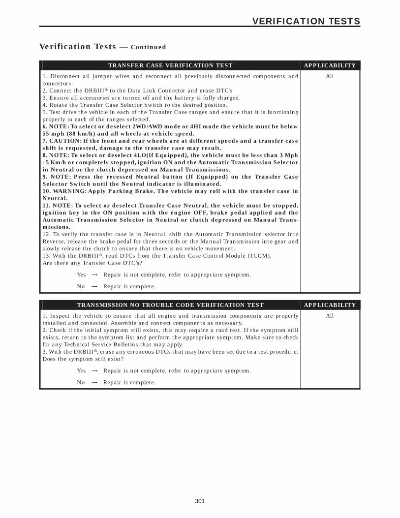
TRANSFER CASE VERIFICATION TEST APPLICABILITY
1. Disconnect all jumper wires and reconnect all previously disconnected components andconnectors.2. Connect the DRBIIIt to the Data Link Connector and erase DTC’s3. Ensure all accessories are turned off and the battery is fully charged.4. Rotate the Transfer Case Selector Switch to the desired position.5. Test drive the vehicle in each of the Transfer Case ranges and ensure that it is functioningproperly in each of the ranges selected.6. NOTE: To select or deselect 2WD/AWD mode or 4HI mode the vehicle must be below55 mph (88 km/h) and all wheels at vehicle speed.7. CAUTION: If the front and rear wheels are at different speeds and a transfer caseshift is requested, damage to the transfer case may result.8. NOTE: To select or deselect 4LO(If Equipped), the vehicle must be less than 3 Mph- 5 Km/h or completely stopped, ignition ON and the Automatic Transmission Selectorin Neutral or the clutch depressed on Manual Transmissions.9. NOTE: Press the recessed Neutral button (If Equipped) on the Transfer CaseSelector Switch until the Neutral indicator is illuminated.10. WARNING: Apply Parking Brake. The vehicle may roll with the transfer case inNeutral.11. NOTE: To select or deselect Transfer Case Neutral, the vehicle must be stopped,ignition key in the ON position with the engine OFF, brake pedal applied and theAutomatic Transmission Selector in Neutral or clutch depressed on Manual Trans-missions.12. To verify the transfer case is in Neutral, shift the Automatic Transmission selector intoReverse, release the brake pedal for three seconds or the Manual Transmission into gear andslowly release the clutch to ensure that there is no vehicle movement.13. With the DRBIIIt, read DTCs from the Transfer Case Control Module (TCCM).Are there any Transfer Case DTC’s?
All
Yes → Repair is not complete, refer to appropriate symptom.
No → Repair is complete.
TRANSMISSION NO TROUBLE CODE VERIFICATION TEST APPLICABILITY
1. Inspect the vehicle to ensure that all engine and transmission components are properlyinstalled and connected. Assemble and connect components as necessary.2. Check if the initial symptom still exists, this may require a road test. If the symptom stillexists, return to the symptom list and perform the appropriate symptom. Make sure to checkfor any Technical Service Bulletins that may apply.3. With the DRBIIIt, erase any erroneous DTCs that may have been set due to a test procedure.Does the symptom still exist?
All
Yes → Repair is not complete, refer to appropriate symptom.
No → Repair is complete.
301
VERIFICATION TESTS
Verification Tests — Continued

NOTES
302
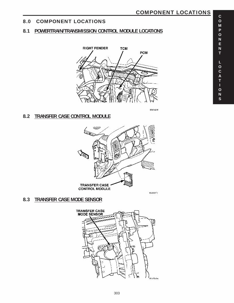
8.0 COMPONENT LOCATIONS
8.1 POWERTRAIN/TRANSMISSION CONTROL MODULE LOCATIONS
8.2 TRANSFER CASE CONTROL MODULE
8.3 TRANSFER CASE MODE SENSOR
COMPONENT
LOCATIONS
303
COMPONENT LOCATIONS
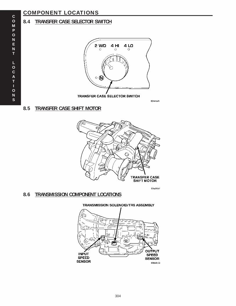
8.4 TRANSFER CASE SELECTOR SWITCH
8.5 TRANSFER CASE SHIFT MOTOR
8.6 TRANSMISSION COMPONENT LOCATIONS
COMPONENT
LOCATIONS
304
COMPONENT LOCATIONS
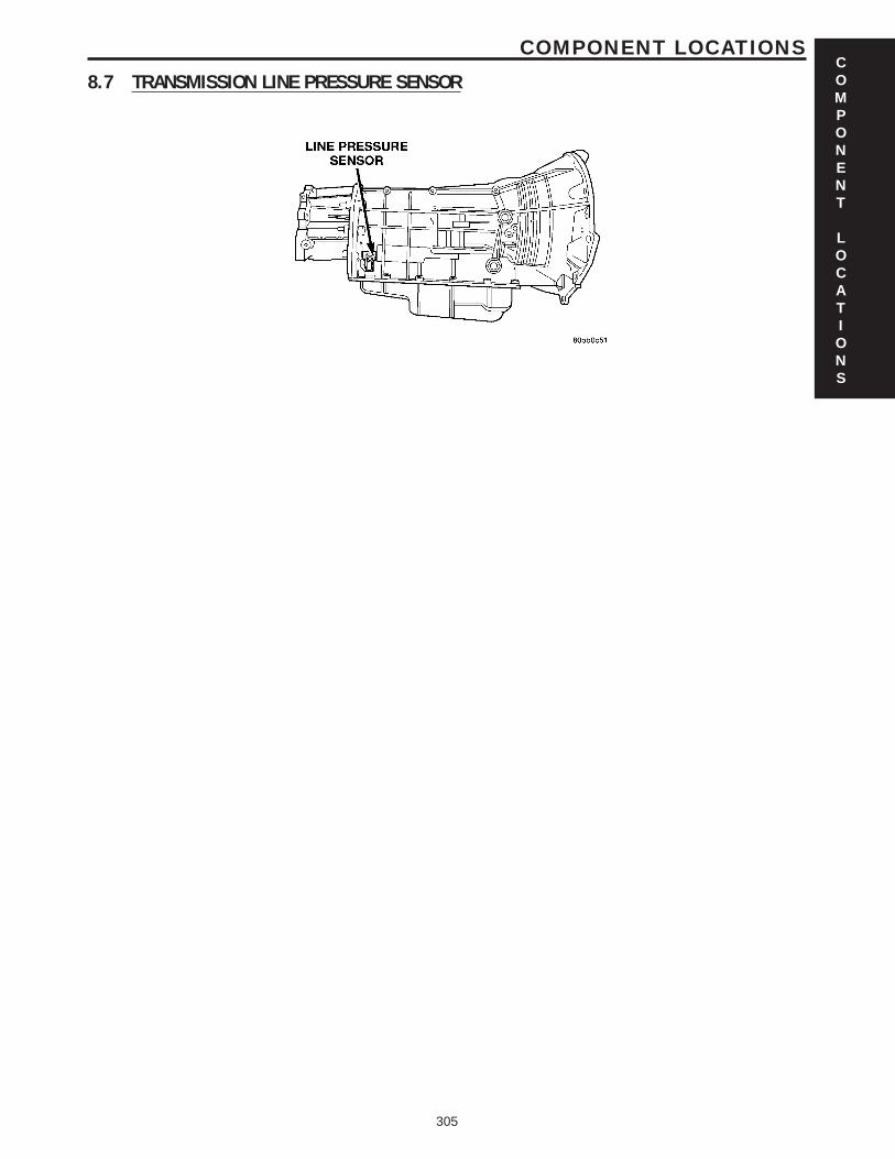
8.7 TRANSMISSION LINE PRESSURE SENSORCOMPONENT
LOCATIONS
305
COMPONENT LOCATIONS

NOTES
306
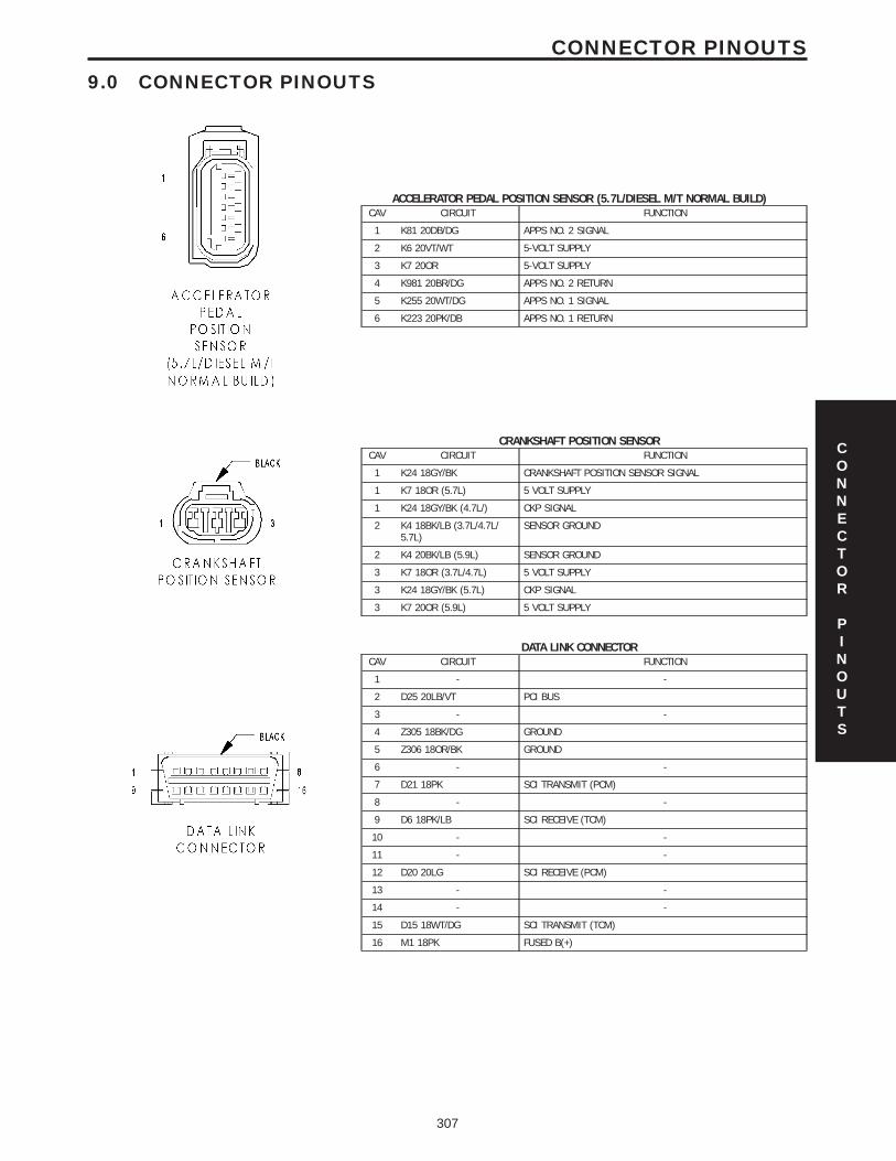
9.0 CONNECTOR PINOUTS
ACCELERATOR PEDAL POSITION SENSOR (5.7L/DIESEL M/T NORMAL BUILD)CAV CIRCUIT FUNCTION
1 K81 20DB/DG APPS NO. 2 SIGNAL
2 K6 20VT/WT 5-VOLT SUPPLY
3 K7 20OR 5-VOLT SUPPLY
4 K981 20BR/DG APPS NO. 2 RETURN
5 K255 20WT/DG APPS NO. 1 SIGNAL
6 K223 20PK/DB APPS NO. 1 RETURN
CRANKSHAFT POSITION SENSORCAV CIRCUIT FUNCTION
1 K24 18GY/BK CRANKSHAFT POSITION SENSOR SIGNAL
1 K7 18OR (5.7L) 5 VOLT SUPPLY
1 K24 18GY/BK (4.7L/) CKP SIGNAL
2 K4 18BK/LB (3.7L/4.7L/5.7L)
SENSOR GROUND
2 K4 20BK/LB (5.9L) SENSOR GROUND
3 K7 18OR (3.7L/4.7L) 5 VOLT SUPPLY
3 K24 18GY/BK (5.7L) CKP SIGNAL
3 K7 20OR (5.9L) 5 VOLT SUPPLY
DATA LINK CONNECTORCAV CIRCUIT FUNCTION
1 - -
2 D25 20LB/VT PCI BUS
3 - -
4 Z305 18BK/DG GROUND
5 Z306 18OR/BK GROUND
6 - -
7 D21 18PK SCI TRANSMIT (PCM)
8 - -
9 D6 18PK/LB SCI RECEIVE (TCM)
10 - -
11 - -
12 D20 20LG SCI RECEIVE (PCM)
13 - -
14 - -
15 D15 18WT/DG SCI TRANSMIT (TCM)
16 M1 18PK FUSED B(+)
CONNECTOR
PINOUTS
307
CONNECTOR PINOUTS
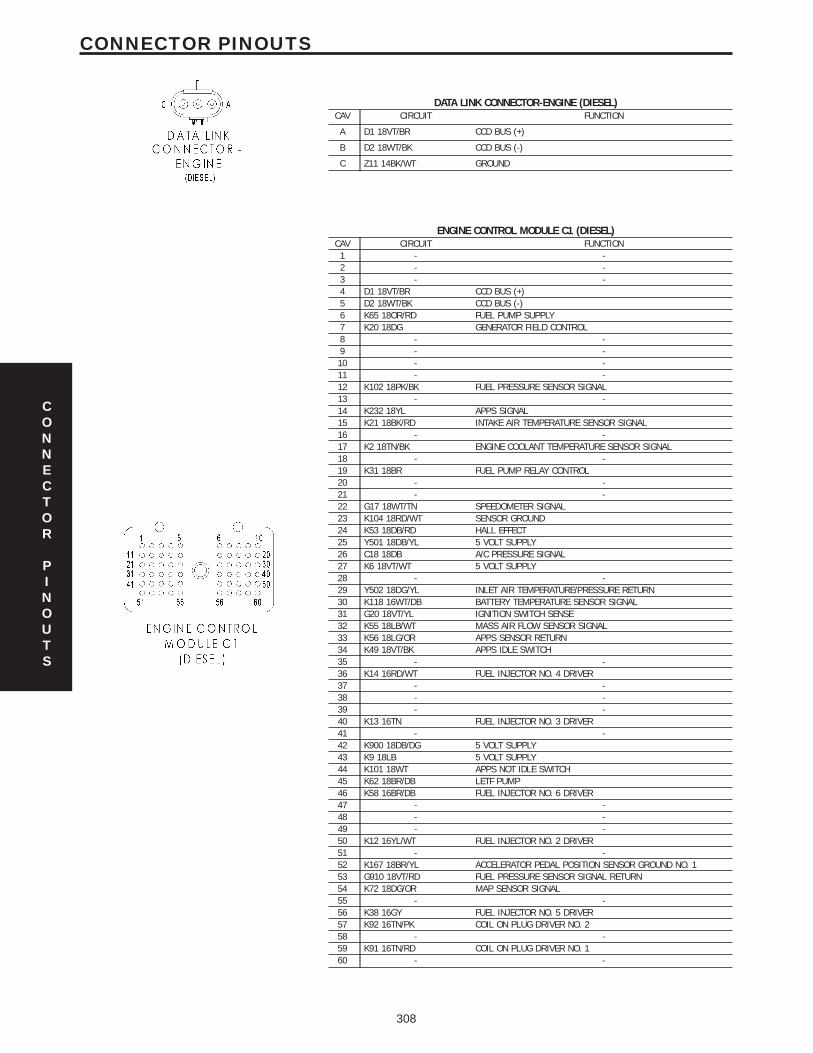
DATA LINK CONNECTOR-ENGINE (DIESEL)CAV CIRCUIT FUNCTION
A D1 18VT/BR CCD BUS (+)
B D2 18WT/BK CCD BUS (-)
C Z11 14BK/WT GROUND
ENGINE CONTROL MODULE C1 (DIESEL)CAV CIRCUIT FUNCTION
1 - -2 - -3 - -4 D1 18VT/BR CCD BUS (+)5 D2 18WT/BK CCD BUS (-)6 K65 18OR/RD FUEL PUMP SUPPLY7 K20 18DG GENERATOR FIELD CONTROL8 - -9 - -10 - -11 - -12 K102 18PK/BK FUEL PRESSURE SENSOR SIGNAL13 - -14 K232 18YL APPS SIGNAL15 K21 18BK/RD INTAKE AIR TEMPERATURE SENSOR SIGNAL16 - -17 K2 18TN/BK ENGINE COOLANT TEMPERATURE SENSOR SIGNAL18 - -19 K31 18BR FUEL PUMP RELAY CONTROL20 - -21 - -22 G17 18WT/TN SPEEDOMETER SIGNAL23 K104 18RD/WT SENSOR GROUND24 K53 18DB/RD HALL EFFECT25 Y501 18DB/YL 5 VOLT SUPPLY26 C18 18DB A/C PRESSURE SIGNAL27 K6 18VT/WT 5 VOLT SUPPLY28 - -29 Y502 18DG/YL INLET AIR TEMPERATURE/PRESSURE RETURN30 K118 16WT/DB BATTERY TEMPERATURE SENSOR SIGNAL31 G20 18VT/YL IGNITION SWITCH SENSE32 K55 18LB/WT MASS AIR FLOW SENSOR SIGNAL33 K56 18LG/OR APPS SENSOR RETURN34 K49 18VT/BK APPS IDLE SWITCH35 - -36 K14 16RD/WT FUEL INJECTOR NO. 4 DRIVER37 - -38 - -39 - -40 K13 16TN FUEL INJECTOR NO. 3 DRIVER41 - -42 K900 18DB/DG 5 VOLT SUPPLY43 K9 18LB 5 VOLT SUPPLY44 K101 18WT APPS NOT IDLE SWITCH45 K62 18BR/DB LETF PUMP46 K58 16BR/DB FUEL INJECTOR NO. 6 DRIVER47 - -48 - -49 - -50 K12 16YL/WT FUEL INJECTOR NO. 2 DRIVER51 - -52 K167 18BR/YL ACCELERATOR PEDAL POSITION SENSOR GROUND NO. 153 G910 18VT/RD FUEL PRESSURE SENSOR SIGNAL RETURN54 K72 18DG/OR MAP SENSOR SIGNAL55 - -56 K38 16GY FUEL INJECTOR NO. 5 DRIVER57 K92 16TN/PK COIL ON PLUG DRIVER NO. 258 - -59 K91 16TN/RD COIL ON PLUG DRIVER NO. 160 - -
CONNECTOR
PINOUTS
308
CONNECTOR PINOUTS
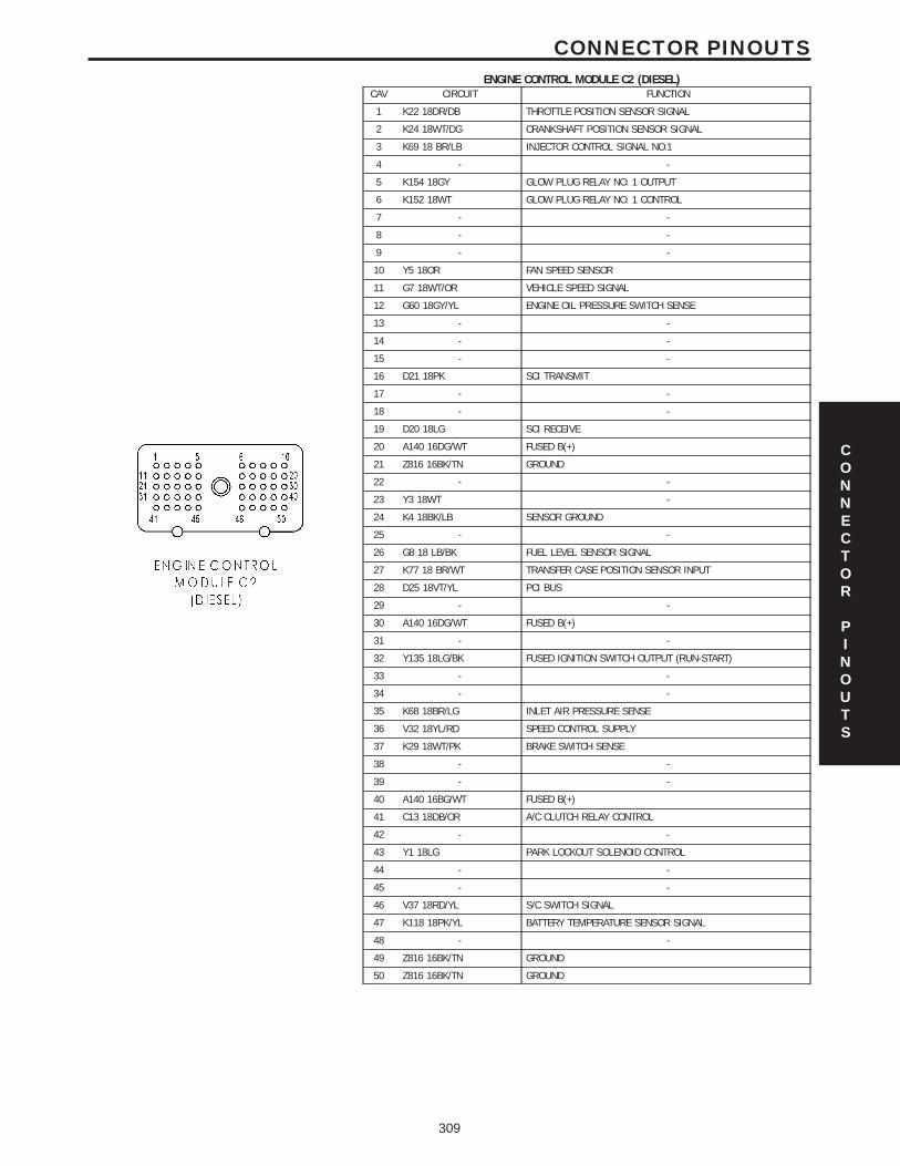
ENGINE CONTROL MODULE C2 (DIESEL)CAV CIRCUIT FUNCTION
1 K22 18DR/DB THROTTLE POSITION SENSOR SIGNAL
2 K24 18WT/DG CRANKSHAFT POSITION SENSOR SIGNAL
3 K69 18 BR/LB INJECTOR CONTROL SIGNAL NO.1
4 - -
5 K154 18GY GLOW PLUG RELAY NO. 1 OUTPUT
6 K152 18WT GLOW PLUG RELAY NO. 1 CONTROL
7 - -
8 - -
9 - -
10 Y5 18OR FAN SPEED SENSOR
11 G7 18WT/OR VEHICLE SPEED SIGNAL
12 G60 18GY/YL ENGINE OIL PRESSURE SWITCH SENSE
13 - -
14 - -
15 - -
16 D21 18PK SCI TRANSMIT
17 - -
18 - -
19 D20 18LG SCI RECEIVE
20 A140 16DG/WT FUSED B(+)
21 Z816 16BK/TN GROUND
22 - -
23 Y3 18WT -
24 K4 18BK/LB SENSOR GROUND
25 - -
26 G8 18 LB/BK FUEL LEVEL SENSOR SIGNAL
27 K77 18 BR/WT TRANSFER CASE POSITION SENSOR INPUT
28 D25 18VT/YL PCI BUS
29 - -
30 A140 16DG/WT FUSED B(+)
31 - -
32 Y135 18LG/BK FUSED IGNITION SWITCH OUTPUT (RUN-START)
33 - -
34 - -
35 K68 18BR/LG INLET AIR PRESSURE SENSE
36 V32 18YL/RD SPEED CONTROL SUPPLY
37 K29 18WT/PK BRAKE SWITCH SENSE
38 - -
39 - -
40 A140 16BG/WT FUSED B(+)
41 C13 18DB/OR A/C CLUTCH RELAY CONTROL
42 - -
43 Y1 18LG PARK LOCKOUT SOLENOID CONTROL
44 - -
45 - -
46 V37 18RD/YL S/C SWITCH SIGNAL
47 K118 18PK/YL BATTERY TEMPERATURE SENSOR SIGNAL
48 - -
49 Z816 16BK/TN GROUND
50 Z816 16BK/TN GROUND
CONNECTOR
PINOUTS
309
CONNECTOR PINOUTS
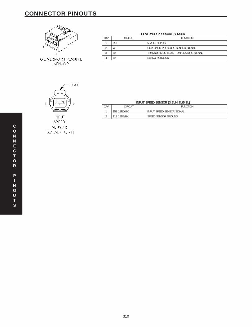
GOVERNOR PRESSURE SENSORCAV CIRCUIT FUNCTION
1 RD 5 VOLT SUPPLY
2 WT GOVERNOR PRESSURE SENSOR SIGNAL
3 BK TRANSMISSION FLUID TEMPERATURE SIGNAL
4 BK SENSOR GROUND
INPUT SPEED SENSOR (3.7L/4.7L/5.7L)CAV CIRCUIT FUNCTION
1 T52 18RD/BK INPUT SPEED SENSOR SIGNAL
2 T13 18DB/BK SPEED SENSOR GROUND
CONNECTOR
PINOUTS
310
CONNECTOR PINOUTS
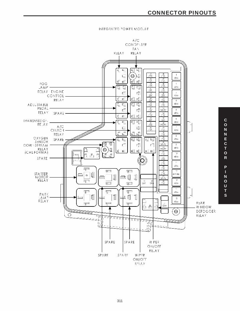
CONNECTOR
PINOUTS
311
CONNECTOR PINOUTS
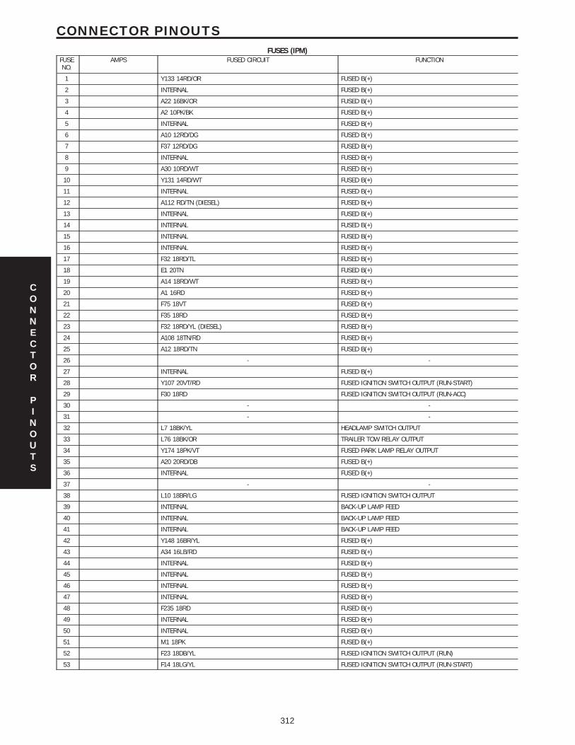
FUSES (IPM)FUSENO.
AMPS FUSED CIRCUIT FUNCTION
1 Y133 14RD/OR FUSED B(+)
2 INTERNAL FUSED B(+)
3 A22 16BK/OR FUSED B(+)
4 A2 10PK/BK FUSED B(+)
5 INTERNAL FUSED B(+)
6 A10 12RD/DG FUSED B(+)
7 F37 12RD/DG FUSED B(+)
8 INTERNAL FUSED B(+)
9 A30 10RD/WT FUSED B(+)
10 Y131 14RD/WT FUSED B(+)
11 INTERNAL FUSED B(+)
12 A112 RD/TN (DIESEL) FUSED B(+)
13 INTERNAL FUSED B(+)
14 INTERNAL FUSED B(+)
15 INTERNAL FUSED B(+)
16 INTERNAL FUSED B(+)
17 F32 18RD/TL FUSED B(+)
18 E1 20TN FUSED B(+)
19 A14 18RD/WT FUSED B(+)
20 A1 16RD FUSED B(+)
21 F75 18VT FUSED B(+)
22 F35 18RD FUSED B(+)
23 F32 18RD/YL (DIESEL) FUSED B(+)
24 A108 18TN/RD FUSED B(+)
25 A12 18RD/TN FUSED B(+)
26 - -
27 INTERNAL FUSED B(+)
28 Y107 20VT/RD FUSED IGNITION SWITCH OUTPUT (RUN-START)
29 F30 18RD FUSED IGNITION SWITCH OUTPUT (RUN-ACC)
30 - -
31 - -
32 L7 18BK/YL HEADLAMP SWITCH OUTPUT
33 L76 18BK/OR TRAILER TOW RELAY OUTPUT
34 Y174 18PK/VT FUSED PARK LAMP RELAY OUTPUT
35 A20 20RD/DB FUSED B(+)
36 INTERNAL FUSED B(+)
37 - -
38 L10 18BR/LG FUSED IGNITION SWITCH OUTPUT
39 INTERNAL BACK-UP LAMP FEED
40 INTERNAL BACK-UP LAMP FEED
41 INTERNAL BACK-UP LAMP FEED
42 Y148 16BR/YL FUSED B(+)
43 A34 16LB/RD FUSED B(+)
44 INTERNAL FUSED B(+)
45 INTERNAL FUSED B(+)
46 INTERNAL FUSED B(+)
47 INTERNAL FUSED B(+)
48 F235 18RD FUSED B(+)
49 INTERNAL FUSED B(+)
50 INTERNAL FUSED B(+)
51 M1 18PK FUSED B(+)
52 F23 18DB/YL FUSED IGNITION SWITCH OUTPUT (RUN)
53 F14 18LG/YL FUSED IGNITION SWITCH OUTPUT (RUN-START)
CONNECTOR
PINOUTS
312
CONNECTOR PINOUTS
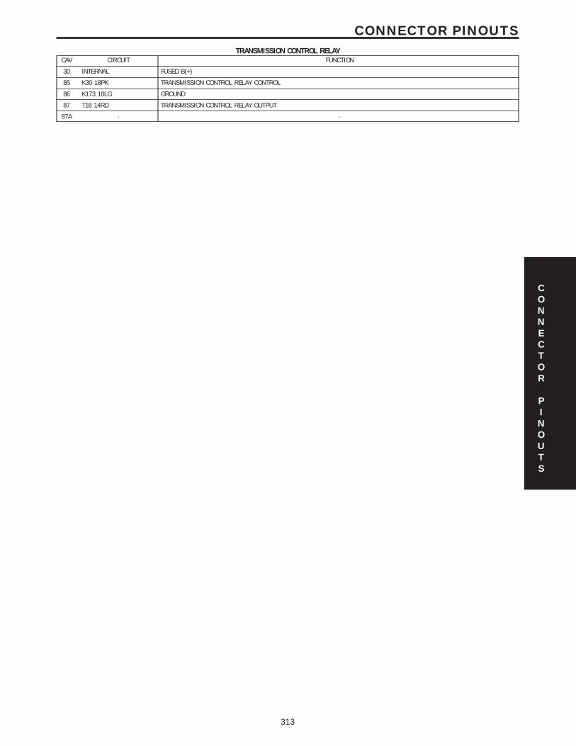
TRANSMISSION CONTROL RELAYCAV CIRCUIT FUNCTION
30 INTERNAL FUSED B(+)
85 K30 18PK TRANSMISSION CONTROL RELAY CONTROL
86 K173 18LG GROUND
87 T16 14RD TRANSMISSION CONTROL RELAY OUTPUT
87A - -
CONNECTOR
PINOUTS
313
CONNECTOR PINOUTS
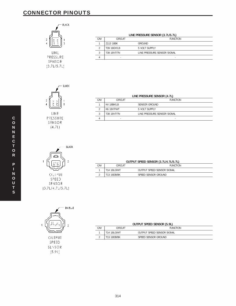
LINE PRESSURE SENSOR (3.7L/5.7L)CAV CIRCUIT FUNCTION
1 Z113 18BK GROUND
2 T39 18GY/LB 5 VOLT SUPPLY
3 T38 18VT/TN LINE PRESSURE SENSOR SIGNAL
4 - -
LINE PRESSURE SENSOR (4.7L)CAV CIRCUIT FUNCTION
1 K4 18BK/LB SENSOR GROUND
2 K6 18VT/WT 5 VOLT SUPPLY
3 T38 18VT/TN LINE PRESSURE SENSOR SIGNAL
4 - -
OUTPUT SPEED SENSOR (3.7L/4.7L/5.7L)CAV CIRCUIT FUNCTION
1 T14 18LG/WT OUTPUT SPEED SENSOR SIGNAL
2 T13 18DB/BK SPEED SENSOR GROUND
OUTPUT SPEED SENSOR (5.9L)CAV CIRCUIT FUNCTION
1 T14 18LG/WT OUTPUT SPEED SENSOR SIGNAL
2 T13 18DB/BK SPEED SENSOR GROUND
CONNECTOR
PINOUTS
314
CONNECTOR PINOUTS
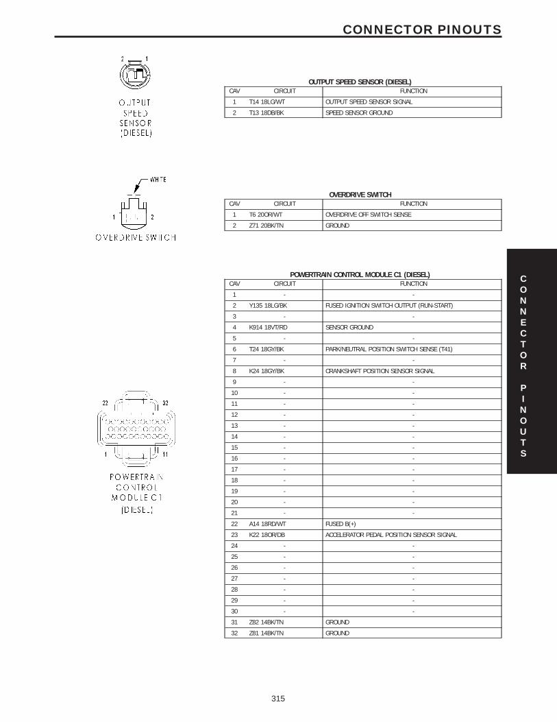
OUTPUT SPEED SENSOR (DIESEL)CAV CIRCUIT FUNCTION
1 T14 18LG/WT OUTPUT SPEED SENSOR SIGNAL
2 T13 18DB/BK SPEED SENSOR GROUND
OVERDRIVE SWITCHCAV CIRCUIT FUNCTION
1 T6 20OR/WT OVERDRIVE OFF SWITCH SENSE
2 Z71 20BK/TN GROUND
POWERTRAIN CONTROL MODULE C1 (DIESEL)CAV CIRCUIT FUNCTION
1 - -
2 Y135 18LG/BK FUSED IGNITION SWITCH OUTPUT (RUN-START)
3 - -
4 K914 18VT/RD SENSOR GROUND
5 - -
6 T24 18GY/BK PARK/NEUTRAL POSITION SWITCH SENSE (T41)
7 - -
8 K24 18GY/BK CRANKSHAFT POSITION SENSOR SIGNAL
9 - -
10 - -
11 - -
12 - -
13 - -
14 - -
15 - -
16 - -
17 - -
18 - -
19 - -
20 - -
21 - -
22 A14 18RD/WT FUSED B(+)
23 K22 18OR/DB ACCELERATOR PEDAL POSITION SENSOR SIGNAL
24 - -
25 - -
26 - -
27 - -
28 - -
29 - -
30 - -
31 Z82 14BK/TN GROUND
32 Z81 14BK/TN GROUND
CONNECTOR
PINOUTS
315
CONNECTOR PINOUTS
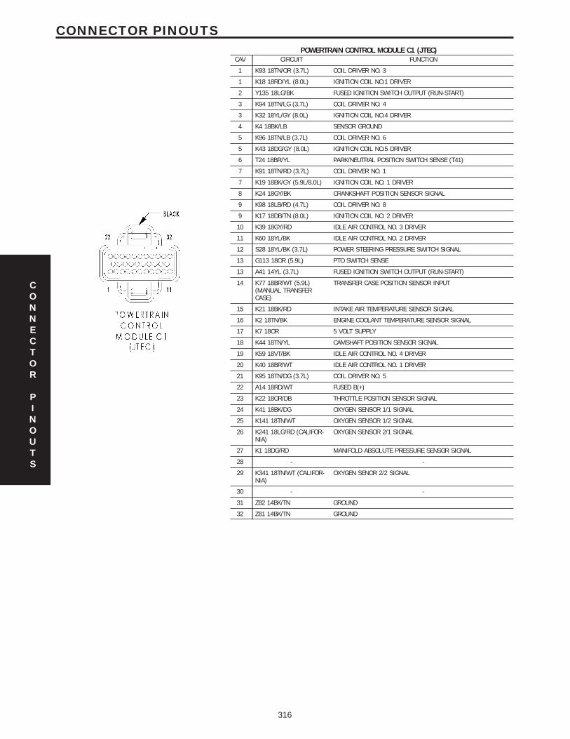
POWERTRAIN CONTROL MODULE C1 (JTEC)CAV CIRCUIT FUNCTION
1 K93 18TN/OR (3.7L) COIL DRIVER NO. 3
1 K18 18RD/YL (8.0L) IGNITION COIL NO.1 DRIVER
2 Y135 18LG/BK FUSED IGNITION SWITCH OUTPUT (RUN-START)
3 K94 18TN/LG (3.7L) COIL DRIVER NO. 4
3 K32 18YL/GY (8.0L) IGNITION COIL NO.4 DRIVER
4 K4 18BK/LB SENSOR GROUND
5 K96 18TN/LB (3.7L) COIL DRIVER NO. 6
5 K43 18DG/GY (8.0L) IGNITION COIL NO.5 DRIVER
6 T24 18BR/YL PARK/NEUTRAL POSITION SWITCH SENSE (T41)
7 K91 18TN/RD (3.7L) COIL DRIVER NO. 1
7 K19 18BK/GY (5.9L/8.0L) IGNITION COIL NO. 1 DRIVER
8 K24 18GY/BK CRANKSHAFT POSITION SENSOR SIGNAL
9 K98 18LB/RD (4.7L) COIL DRIVER NO. 8
9 K17 18DB/TN (8.0L) IGNITION COIL NO. 2 DRIVER
10 K39 18GY/RD IDLE AIR CONTROL NO. 3 DRIVER
11 K60 18YL/BK IDLE AIR CONTROL NO. 2 DRIVER
12 S28 18YL/BK (3.7L) POWER STEERING PRESSURE SWITCH SIGNAL
13 G113 18OR (5.9L) PTO SWITCH SENSE
13 A41 14YL (3.7L) FUSED IGNITION SWITCH OUTPUT (RUN-START)
14 K77 18BR/WT (5.9L)(MANUAL TRANSFERCASE)
TRANSFER CASE POSITION SENSOR INPUT
15 K21 18BK/RD INTAKE AIR TEMPERATURE SENSOR SIGNAL
16 K2 18TN/BK ENGINE COOLANT TEMPERATURE SENSOR SIGNAL
17 K7 18OR 5 VOLT SUPPLY
18 K44 18TN/YL CAMSHAFT POSITION SENSOR SIGNAL
19 K59 18VT/BK IDLE AIR CONTROL NO. 4 DRIVER
20 K40 18BR/WT IDLE AIR CONTROL NO. 1 DRIVER
21 K95 18TN/DG (3.7L) COIL DRIVER NO. 5
22 A14 18RD/WT FUSED B(+)
23 K22 18OR/DB THROTTLE POSITION SENSOR SIGNAL
24 K41 18BK/DG OXYGEN SENSOR 1/1 SIGNAL
25 K141 18TN/WT OXYGEN SENSOR 1/2 SIGNAL
26 K241 18LG/RD (CALIFOR-NIA)
OXYGEN SENSOR 2/1 SIGNAL
27 K1 18DG/RD MANIFOLD ABSOLUTE PRESSURE SENSOR SIGNAL
28 - -
29 K341 18TN/WT (CALIFOR-NIA)
OXYGEN SENOR 2/2 SIGNAL
30 - -
31 Z82 14BK/TN GROUND
32 Z81 14BK/TN GROUND
CONNECTOR
PINOUTS
316
CONNECTOR PINOUTS
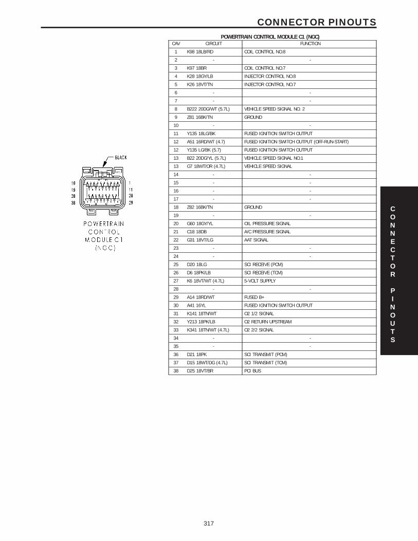
POWERTRAIN CONTROL MODULE C1 (NGC)CAV CIRCUIT FUNCTION
1 K98 18LB/RD COIL CONTROL NO.8
2 - -
3 K97 18BR COIL CONTROL NO.7
4 K28 18GY/LB INJECTOR CONTROL NO.8
5 K26 18VT/TN INJECTOR CONTROL NO.7
6 - -
7 - -
8 B222 20DG/WT (5.7L) VEHICLE SPEED SIGNAL NO. 2
9 Z81 16BK/TN GROUND
10 - -
11 Y135 18LG/BK FUSED IGNITION SWITCH OUTPUT
12 A51 16RD/WT (4.7) FUSED IGNITION SWITCH OUTPUT (OFF-RUN-START)
12 Y135 LG/BK (5.7) FUSED IGNITION SWITCH OUTPUT
13 B22 20DG/YL (5.7L) VEHICLE SPEED SIGNAL NO.1
13 G7 18WT/OR (4.7L) VEHICLE SPEED SIGNAL
14 - -
15 - -
16 - -
17 - -
18 Z82 16BK/TN GROUND
19 - -
20 G60 18GY/YL OIL PRESSURE SIGNAL
21 C18 18DB A/C PRESSURE SIGNAL
22 G31 18VT/LG AAT SIGNAL
23 - -
24 - -
25 D20 18LG SCI RECEIVE (PCM)
26 D6 18PK/LB SCI RECEIVE (TCM)
27 K6 18VT/WT (4.7L) 5-VOLT SUPPLY
28 - -
29 A14 18RD/WT FUSED B+
30 A41 16YL FUSED IGNITION SWITCH OUTPUT
31 K141 18TN/WT O2 1/2 SIGNAL
32 Y213 18PK/LB O2 RETURN UPSTREAM
33 K341 18TN/WT (4.7L) O2 2/2 SIGNAL
34 - -
35 - -
36 D21 18PK SCI TRANSMIT (PCM)
37 D15 18WT/DG (4.7L) SCI TRANSMIT (TCM)
38 D25 18VT/BR PCI BUS
CONNECTOR
PINOUTS
317
CONNECTOR PINOUTS
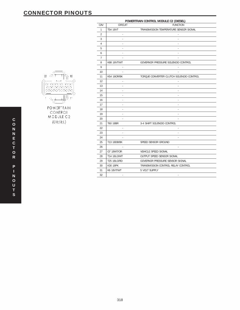
POWERTRAIN CONTROL MODULE C2 (DIESEL)CAV CIRCUIT FUNCTION
1 T54 18VT TRANSMISSION TEMPERATURE SENSOR SIGNAL
2 - -
3 - -
4 - -
5 - -
6 - -
7 - -
8 K88 18VT/WT GOVERNOR PRESSURE SOLENOID CONTROL
9 - -
10 - -
11 K54 18OR/BK TORQUE CONVERTER CLUTCH SOLENOID CONTROL
12 - -
13 - -
14 - -
15 - -
16 - -
17 - -
18 - -
19 - -
20 - -
21 T60 18BR 3-4 SHIFT SOLENOID CONTROL
22 - -
23 - -
24 - -
25 T13 18DB/BK SPEED SENSOR GROUND
26 - -
27 G7 18WT/OR VEHICLE SPEED SIGNAL
28 T14 18LG/WT OUTPUT SPEED SENSOR SIGNAL
29 T25 18LG/RD GOVERNOR PRESSURE SENSOR SIGNAL
30 K30 18PK TRANSMISSION CONTROL RELAY CONTROL
31 K6 18VT/WT 5 VOLT SUPPLY
32 - -
CONNECTOR
PINOUTS
318
CONNECTOR PINOUTS
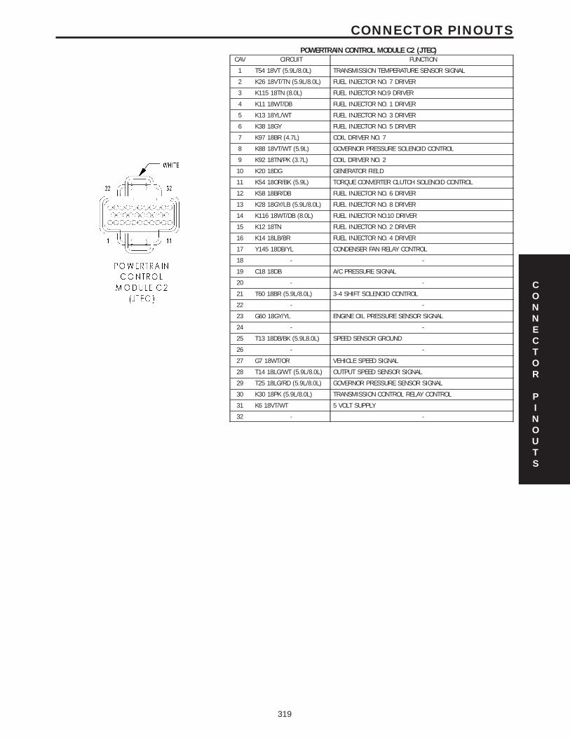
POWERTRAIN CONTROL MODULE C2 (JTEC)CAV CIRCUIT FUNCTION
1 T54 18VT (5.9L/8.0L) TRANSMISSION TEMPERATURE SENSOR SIGNAL
2 K26 18VT/TN (5.9L/8.0L) FUEL INJECTOR NO. 7 DRIVER
3 K115 18TN (8.0L) FUEL INJECTOR NO.9 DRIVER
4 K11 18WT/DB FUEL INJECTOR NO. 1 DRIVER
5 K13 18YL/WT FUEL INJECTOR NO. 3 DRIVER
6 K38 18GY FUEL INJECTOR NO. 5 DRIVER
7 K97 18BR (4.7L) COIL DRIVER NO. 7
8 K88 18VT/WT (5.9L) GOVERNOR PRESSURE SOLENOID CONTROL
9 K92 18TN/PK (3.7L) COIL DRIVER NO. 2
10 K20 18DG GENERATOR FIELD
11 K54 18OR/BK (5.9L) TORQUE CONVERTER CLUTCH SOLENOID CONTROL
12 K58 18BR/DB FUEL INJECTOR NO. 6 DRIVER
13 K28 18GY/LB (5.9L/8.0L) FUEL INJECTOR NO. 8 DRIVER
14 K116 18WT/DB (8.0L) FUEL INJECTOR NO.10 DRIVER
15 K12 18TN FUEL INJECTOR NO. 2 DRIVER
16 K14 18LB/BR FUEL INJECTOR NO. 4 DRIVER
17 Y145 18DB/YL CONDENSER FAN RELAY CONTROL
18 - -
19 C18 18DB A/C PRESSURE SIGNAL
20 - -
21 T60 18BR (5.9L/8.0L) 3-4 SHIFT SOLENOID CONTROL
22 - -
23 G60 18GY/YL ENGINE OIL PRESSURE SENSOR SIGNAL
24 - -
25 T13 18DB/BK (5.9L8.0L) SPEED SENSOR GROUND
26 - -
27 G7 18WT/OR VEHICLE SPEED SIGNAL
28 T14 18LG/WT (5.9L/8.0L) OUTPUT SPEED SENSOR SIGNAL
29 T25 18LG/RD (5.9L/8.0L) GOVERNOR PRESSURE SENSOR SIGNAL
30 K30 18PK (5.9L/8.0L) TRANSMISSION CONTROL RELAY CONTROL
31 K6 18VT/WT 5 VOLT SUPPLY
32 - -
CONNECTOR
PINOUTS
319
CONNECTOR PINOUTS
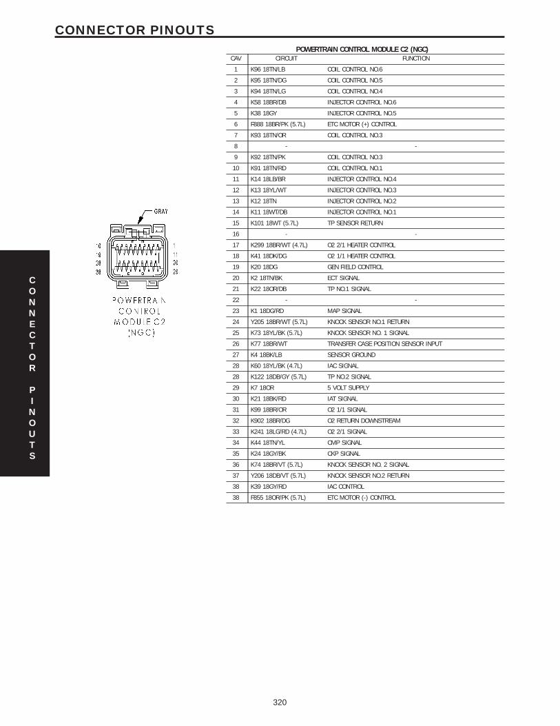
POWERTRAIN CONTROL MODULE C2 (NGC)CAV CIRCUIT FUNCTION
1 K96 18TN/LB COIL CONTROL NO.6
2 K95 18TN/DG COIL CONTROL NO.5
3 K94 18TN/LG COIL CONTROL NO.4
4 K58 18BR/DB INJECTOR CONTROL NO.6
5 K38 18GY INJECTOR CONTROL NO.5
6 F888 18BR/PK (5.7L) ETC MOTOR (+) CONTROL
7 K93 18TN/OR COIL CONTROL NO.3
8 - -
9 K92 18TN/PK COIL CONTROL NO.3
10 K91 18TN/RD COIL CONTROL NO.1
11 K14 18LB/BR INJECTOR CONTROL NO.4
12 K13 18YL/WT INJECTOR CONTROL NO.3
13 K12 18TN INJECTOR CONTROL NO.2
14 K11 18WT/DB INJECTOR CONTROL NO.1
15 K101 18WT (5.7L) TP SENSOR RETURN
16 - -
17 K299 18BR/WT (4.7L) O2 2/1 HEATER CONTROL
18 K41 18DK/DG O2 1/1 HEATER CONTROL
19 K20 18DG GEN FIELD CONTROL
20 K2 18TN/BK ECT SIGNAL
21 K22 18OR/DB TP NO.1 SIGNAL
22 - -
23 K1 18DG/RD MAP SIGNAL
24 Y205 18BR/WT (5.7L) KNOCK SENSOR NO.1 RETURN
25 K73 18YL/BK (5.7L) KNOCK SENSOR NO. 1 SIGNAL
26 K77 18BR/WT TRANSFER CASE POSITION SENSOR INPUT
27 K4 18BK/LB SENSOR GROUND
28 K60 18YL/BK (4.7L) IAC SIGNAL
28 K122 18DB/GY (5.7L) TP NO.2 SIGNAL
29 K7 18OR 5 VOLT SUPPLY
30 K21 18BK/RD IAT SIGNAL
31 K99 18BR/OR O2 1/1 SIGNAL
32 K902 18BR/DG O2 RETURN DOWNSTREAM
33 K241 18LG/RD (4.7L) O2 2/1 SIGNAL
34 K44 18TN/YL CMP SIGNAL
35 K24 18GY/BK CKP SIGNAL
36 K74 18BR/VT (5.7L) KNOCK SENSOR NO. 2 SIGNAL
37 Y206 18DB/VT (5.7L) KNOCK SENSOR NO.2 RETURN
38 K39 18GY/RD IAC CONTROL
38 F855 18OR/PK (5.7L) ETC MOTOR (-) CONTROL
CONNECTOR
PINOUTS
320
CONNECTOR PINOUTS
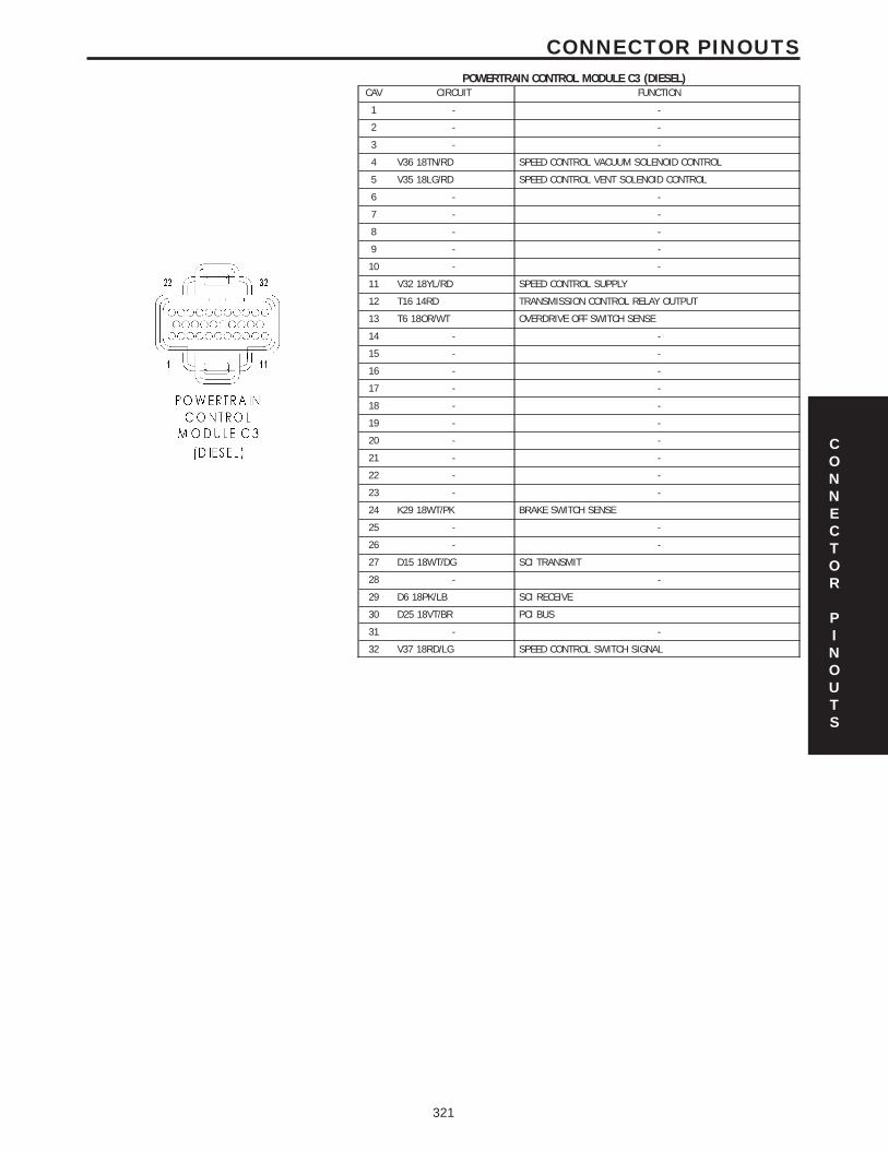
POWERTRAIN CONTROL MODULE C3 (DIESEL)CAV CIRCUIT FUNCTION
1 - -
2 - -
3 - -
4 V36 18TN/RD SPEED CONTROL VACUUM SOLENOID CONTROL
5 V35 18LG/RD SPEED CONTROL VENT SOLENOID CONTROL
6 - -
7 - -
8 - -
9 - -
10 - -
11 V32 18YL/RD SPEED CONTROL SUPPLY
12 T16 14RD TRANSMISSION CONTROL RELAY OUTPUT
13 T6 18OR/WT OVERDRIVE OFF SWITCH SENSE
14 - -
15 - -
16 - -
17 - -
18 - -
19 - -
20 - -
21 - -
22 - -
23 - -
24 K29 18WT/PK BRAKE SWITCH SENSE
25 - -
26 - -
27 D15 18WT/DG SCI TRANSMIT
28 - -
29 D6 18PK/LB SCI RECEIVE
30 D25 18VT/BR PCI BUS
31 - -
32 V37 18RD/LG SPEED CONTROL SWITCH SIGNAL
CONNECTOR
PINOUTS
321
CONNECTOR PINOUTS
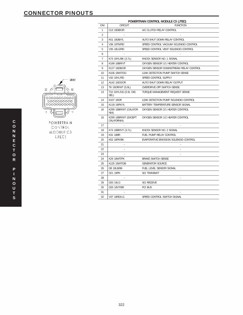
POWERTRAIN CONTROL MODULE C3 (JTEC)CAV CIRCUIT FUNCTION
1 C13 18DB/OR A/C CLUTCH RELAY CONTROL
2 - -
3 K51 18DB/YL AUTO SHUT DOWN RELAY CONTROL
4 V36 18TN/RD SPEED CONTROL VACUUM SOLENOID CONTROL
5 V35 18LG/RD SPEED CONTROL VENT SOLENOID CONTROL
6 - -
7 K73 18YL/BK (3.7L) KNOCK SENSOR NO. 1 SIGNAL
8 K199 18BR/VT OXYGEN SENSOR 1/1 HEATER CONTROL
9 K127 18DB/OR OXYGEN SENSOR DOWNSTREAM RELAY CONTROL
10 K106 18WT/DG LEAK DETECTION PUMP SWITCH SENSE
11 V32 18YL/RD SPEED CONTROL SUPPLY
12 A142 16DG/OR AUTO SHUT DOWN RELAY OUTPUT
13 T6 18OR/WT (5.9L) OVERDRIVE OFF SWITCH SENSE
13 T10 18YL/DG (5.9L DIE-SEL)
TORQUE MANAGEMENT REQUEST SENSE
14 K107 18OR LEAK DETECTION PUMP SOLENOID CONTROL
15 K118 18PK/YL BATTERY TEMPERATURE SENSOR SIGNAL
16 K299 18BR/WT (CALIFOR-NIA)
OXYGEN SENSOR 2/1 HEATER CONTROL
16 K299 18BR/WT (EXCEPTCALIFORNIA)
OXYGEN SENSOR 1/2 HEATER CONTROL
17 - -
18 K74 18BR/VT (3.7L) KNOCK SENSOR NO. 2 SIGNAL
19 K31 18BR FUEL PUMP RELAY CONTROL
20 K52 18PK/BK EVAPORATIVE EMISSION SOLENOID CONTROL
21 - -
22 - -
23 - -
24 K29 18WT/PK BRAKE SWITCH SENSE
25 K125 18WT/DB GENERATOR SOURCE
26 G8 18LB/BK FUEL LEVEL SENSOR SIGNAL
27 D21 18PK SCI TRANSMIT
28 - -
29 D20 18LG SCI RECEIVE
30 D25 18VT/BR PCI BUS
31 - -
32 V37 18RD/LG SPEED CONTROL SWITCH SIGNAL
CONNECTOR
PINOUTS
322
CONNECTOR PINOUTS
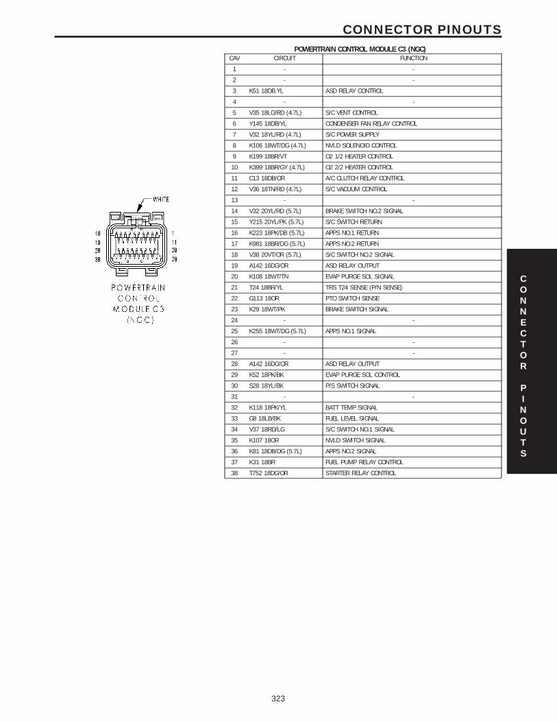
POWERTRAIN CONTROL MODULE C3 (NGC)CAV CIRCUIT FUNCTION
1 - -
2 - -
3 K51 18DB.YL ASD RELAY CONTROL
4 - -
5 V35 18LG/RD (4.7L) S/C VENT CONTROL
6 Y145 18DB/YL CONDENSER FAN RELAY CONTROL
7 V32 18YL/RD (4.7L) S/C POWER SUPPLY
8 K106 18WT/DG (4.7L) NVLD SOLENOID CONTROL
9 K199 18BR/VT O2 1/2 HEATER CONTROL
10 K399 18BR/GY (4.7L) O2 2/2 HEATER CONTROL
11 C13 18DB/OR A/C CLUTCH RELAY CONTROL
12 V36 18TN/RD (4.7L) S/C VACUUM CONTROL
13 - -
14 V32 20YL/RD (5.7L) BRAKE SWITCH NO.2 SIGNAL
15 Y215 20YL/PK (5.7L) S/C SWITCH RETURN
16 K223 18PK/DB (5.7L) APPS NO.1 RETURN
17 K981 18BR/DG (5.7L) APPS NO.2 RETURN
18 V38 20VT/OR (5.7L) S/C SWITCH NO.2 SIGNAL
19 A142 16DG/OR ASD RELAY OUTPUT
20 K108 18WT/TN EVAP PURGE SOL SIGNAL
21 T24 18BR/YL TRS T24 SENSE (P/N SENSE)
22 G113 18OR PTO SWITCH SENSE
23 K29 18WT/PK BRAKE SWITCH SIGNAL
24 - -
25 K255 18WT/DG (5.7L) APPS NO.1 SIGNAL
26 - -
27 - -
28 A142 16DG/OR ASD RELAY OUTPUT
29 K52 18PK/BK EVAP PURGE SOL CONTROL
30 S28 18YL/BK P/S SWITCH SIGNAL
31 - -
32 K118 18PK/YL BATT TEMP SIGNAL
33 G8 18LB/BK FUEL LEVEL SIGNAL
34 V37 18RD/LG S/C SWITCH NO.1 SIGNAL
35 K107 18OR NVLD SWITCH SIGNAL
36 K81 18DB/DG (5.7L) APPS NO.2 SIGNAL
37 K31 18BR FUEL PUMP RELAY CONTROL
38 T752 18DG/OR STARTER RELAY CONTROL
CONNECTOR
PINOUTS
323
CONNECTOR PINOUTS
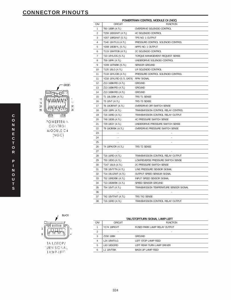
POWERTRAIN CONTROL MODULE C4 (NGC)CAV CIRCUIT FUNCTION
1 T60 18BR (4.7L) OVERDRIVE SOLENOID CONTROL
2 T159 18DG/WT (4.7L) 4C SOLENOID CONTROL
3 Y207 18RD/WT (5.7L) TPS NO. 1 OUTPUT
4 T140 18VT/LG (4.7L) PRESSURE CONTROL SOLENOID CONTROL
5 Y208 18DB/YL (5.7L) APPS NO. 1 OUTPUT
6 T119 18WT/DB (4.7L) 2C SOLENOID CONTROL
7 T10 18YL/DG (5.7L) TORQUE MANAGEMENT REQUEST SENSE
8 T59 18PK (4.7L) UNDERDRIVE SOLENOID CONTROL
9 Y209 18TN/BK (5.7L) SENSOR GROUND
10 T120 18LG (4.7L) LR SOLENOID CONTROL
11 T118 18YL/DB (4.7L) PRESSURE CONTROL SOLENOID CONTROL
11 Y210 18YL/RD (5.7L EATX) RPM SIGNAL
12 Z13 16BK/RD (4.7L) GROUND
13 Z13 16BK/RD (4.7L) GROUND
14 Z13 16BK/RD (4.7L) GROUND
15 T1 18LG/BK (4.7L) TRS T1 SENSE
16 T3 18VT (4.7L) TRS T3 SENSE
17 T6 18OR/WT (4.7L) OVERDRIVE OFF SWITCH SENSE
18 K30 18PK (4.7L) TRANSMISSION CONTROL RELAY CONTROL
19 T16 16RD (4.7L) TRANSMISSION CONTROL RELAY OUTPUT
20 T48 18DB (4.7L) 4C PRESSURE SWITCH SENSE
21 T29 18GY (4.7L) UNDERDRIVE PRESSURE SWITCH SENSE
22 T9 18OR/BK (4.7L) OVERDRIVE PRESSURE SWITCH SENSE
23 - -
24 - -
25 - -
26 T4 18PK/OR (4.7L) TRS T2 SENSE
27 - -
28 T16 16RD (4.7L) TRANSMISSION CONTROL RELAY OUTPUT
29 T50 18DG (4.7L) LOW/REVERSE PRESSURE SWITCH SENSE
30 T147 18LB (4.7L) 2C PRESSURE SWITCH SENSE
31 T38 18VT/TN (4.7L) LINE PRESSURE SENSOR SIGNAL
32 T14 18LG/WT (4.7L) OUTPUT SPEED SENSOR SIGNAL
33 T52 18RD/BK (4.7L) INPUT SPEED SENSOR SIGNAL
34 T13 18DB/BK (4.7L) SPEED SENSOR GROUND
35 T54 18VT (4.7L) TRANSMISSION TEMPERATURE SENSOR SIGNAL
36 - -
37 T42 18VT/WT (4.7L) TRS T42 SENSE
38 T16 16RD (4.7L) TRANSMISSION CONTROL RELAY OUTPUT
TAIL/STOP/TURN SIGNAL LAMP-LEFTCAV CIRCUIT FUNCTION
1 Y174 18PK/VT FUSED PARK LAMP RELAY OUTPUT
2 - -
3 Z150 18BK GROUND
4 L24 18WT/LG LEFT STOP LAMP FEED
5 L63 18DG/RD LEFT REAR TURN LAMP DRIVER
6 L1 18VT/BK BACK-UP LAMP FEED
CONNECTOR
PINOUTS
324
CONNECTOR PINOUTS
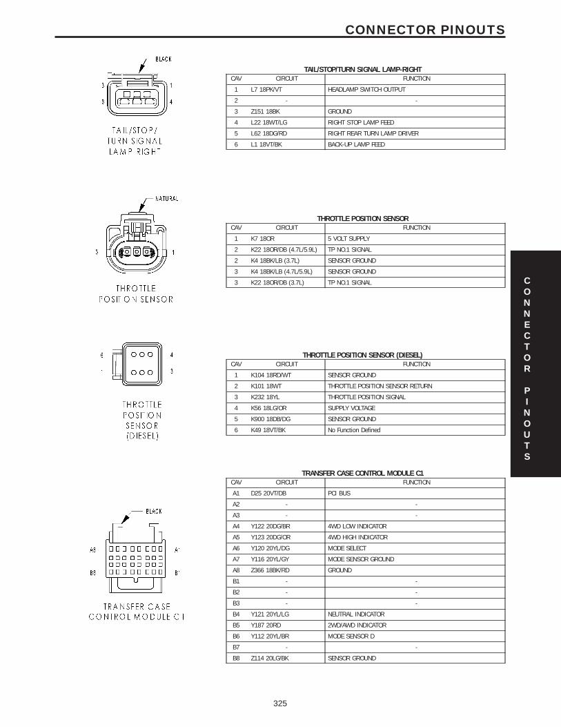
TAIL/STOP/TURN SIGNAL LAMP-RIGHTCAV CIRCUIT FUNCTION
1 L7 18PK/VT HEADLAMP SWITCH OUTPUT
2 - -
3 Z151 18BK GROUND
4 L22 18WT/LG RIGHT STOP LAMP FEED
5 L62 18DG/RD RIGHT REAR TURN LAMP DRIVER
6 L1 18VT/BK BACK-UP LAMP FEED
THROTTLE POSITION SENSORCAV CIRCUIT FUNCTION
1 K7 18OR 5 VOLT SUPPLY
2 K22 18OR/DB (4.7L/5.9L) TP NO.1 SIGNAL
2 K4 18BK/LB (3.7L) SENSOR GROUND
3 K4 18BK/LB (4.7L/5.9L) SENSOR GROUND
3 K22 18OR/DB (3.7L) TP NO.1 SIGNAL
THROTTLE POSITION SENSOR (DIESEL)CAV CIRCUIT FUNCTION
1 K104 18RD/WT SENSOR GROUND
2 K101 18WT THROTTLE POSITION SENSOR RETURN
3 K232 18YL THROTTLE POSITION SIGNAL
4 K56 18LG/OR SUPPLY VOLTAGE
5 K900 18DB/DG SENSOR GROUND
6 K49 18VT/BK No Function Defined
TRANSFER CASE CONTROL MODULE C1CAV CIRCUIT FUNCTION
A1 D25 20VT/DB PCI BUS
A2 - -
A3 - -
A4 Y122 20DG/BR 4WD LOW INDICATOR
A5 Y123 20DG/OR 4WD HIGH INDICATOR
A6 Y120 20YL/DG MODE SELECT
A7 Y116 20YL/GY MODE SENSOR GROUND
A8 Z366 18BK/RD GROUND
B1 - -
B2 - -
B3 - -
B4 Y121 20YL/LG NEUTRAL INDICATOR
B5 Y187 20RD 2WD/AWD INDICATOR
B6 Y112 20YL/BR MODE SENSOR D
B7 - -
B8 Z114 20LG/BK SENSOR GROUND
CONNECTOR
PINOUTS
325
CONNECTOR PINOUTS
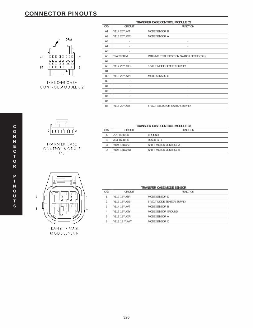
TRANSFER CASE CONTROL MODULE C2CAV CIRCUIT FUNCTION
A1 Y114 20YL/VT MODE SENSOR B
A2 Y113 20YL/OR MODE SENSOR A
A3 - -
A4 - -
A5 - -
A6 T24 20BR/YL PARK/NEUTRAL POSITION SWITCH SENSE (T41)
A7 - -
A8 Y117 20YL/DB 5 VOLT MODE SENSOR SUPPLY
B1 - -
B2 Y115 20YL/WT MODE SENSOR C
B3 - -
B4 - -
B5 - -
B6 - -
B7 - -
B8 Y118 20YL/LB 5 VOLT SELECTOR SWITCH SUPPLY
TRANSFER CASE CONTROL MODULE C3CAV CIRCUIT FUNCTION
A Z21 16BK/LG GROUND
B A34 16LB/RD FUSED B(+)
C Y124 16DG/VT SHIFT MOTOR CONTROL A
D Y125 16DG/WT SHIFT MOTOR CONTROL B
TRANSFER CASE MODE SENSORCAV CIRCUIT FUNCTION
1 Y112 18YL/BR MODE SENSOR D
2 Y117 18YL/DB 5 VOLT MODE SENSOR SUPPLY
3 Y114 18YL/VT MODE SENSOR B
4 Y116 18YL/GY MODE SENSOR GROUND
5 Y113 18YL/OR MODE SENSOR A
6 Y115 18 YL/WT MODE SENSOR C
CONNECTOR
PINOUTS
326
CONNECTOR PINOUTS
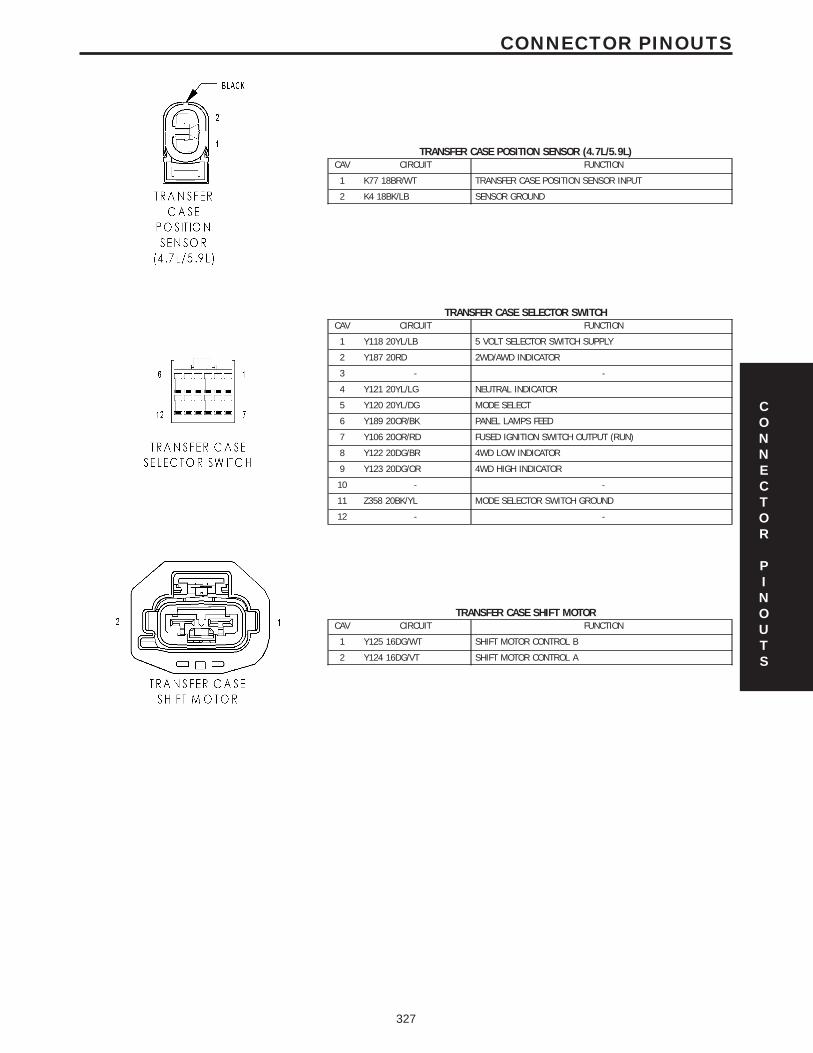
TRANSFER CASE POSITION SENSOR (4.7L/5.9L)CAV CIRCUIT FUNCTION
1 K77 18BR/WT TRANSFER CASE POSITION SENSOR INPUT
2 K4 18BK/LB SENSOR GROUND
TRANSFER CASE SELECTOR SWITCHCAV CIRCUIT FUNCTION
1 Y118 20YL/LB 5 VOLT SELECTOR SWITCH SUPPLY
2 Y187 20RD 2WD/AWD INDICATOR
3 - -
4 Y121 20YL/LG NEUTRAL INDICATOR
5 Y120 20YL/DG MODE SELECT
6 Y189 20OR/BK PANEL LAMPS FEED
7 Y106 20OR/RD FUSED IGNITION SWITCH OUTPUT (RUN)
8 Y122 20DG/BR 4WD LOW INDICATOR
9 Y123 20DG/OR 4WD HIGH INDICATOR
10 - -
11 Z358 20BK/YL MODE SELECTOR SWITCH GROUND
12 - -
TRANSFER CASE SHIFT MOTORCAV CIRCUIT FUNCTION
1 Y125 16DG/WT SHIFT MOTOR CONTROL B
2 Y124 16DG/VT SHIFT MOTOR CONTROL A
CONNECTOR
PINOUTS
327
CONNECTOR PINOUTS
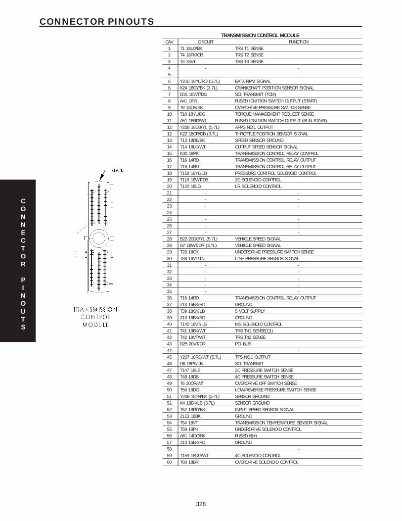
TRANSMISSION CONTROL MODULECAV CIRCUIT FUNCTION
1 T1 18LG/BK TRS T1 SENSE2 T4 18PK/OR TRS T2 SENSE3 T3 18VT TRS T3 SENSE4 - -5 - -6 Y210 18YL/RD (5.7L) EATX RPM SIGNAL6 K24 18GY/BK (3.7L) CRANKSHAFT POSITION SENSOR SIGNAL7 D15 18WT/DG SCI TRANSMIT (TCM)8 A41 16YL FUSED IGNITION SWITCH OUTPUT (START)9 T9 18OR/BK OVERDRIVE PRESSURE SWITCH SENSE10 T10 18YL/DG TORQUE MANAGEMENT REQUEST SENSE11 A51 16RD/WT FUSED IGNITION SWITCH OUTPUT (RUN-START)12 Y208 18DB/YL (5.7L) APPS NO.1 OUTPUT12 K22 18OR/DB (3.7L) THROTTLE POSITION SENSOR SIGNAL13 T13 18DB/BK SPEED SENSOR GROUND14 T14 18LG/WT OUTPUT SPEED SENSOR SIGNAL15 K30 19PK TRANSMISSION CONTROL RELAY CONTROL16 T16 14RD TRANSMISSION CONTROL RELAY OUTPUT17 T16 14RD TRANSMISSION CONTROL RELAY OUTPUT18 T118 18YL/DB PRESSURE CONTROL SOLENOID CONTROL19 T119 18WT/DB 2C SOLENOID CONTROL20 T120 18LG LR SOLENOID CONTROL21 - -22 - -23 - -24 - -25 - -26 - -27 - -28 B22 20DG/YL (5.7L) VEHICLE SPEED SIGNAL28 G7 18WT/OR (3.7L) VEHICLE SPEED SIGNAL29 T29 18GY UNDERDRIVE PRESSURE SWITCH SENSE30 T38 18VT/TN LINE PRESSURE SENSOR SIGNAL31 - -32 - -33 - -34 - -35 - -36 T16 14RD TRANSMISSION CONTROL RELAY OUTPUT37 Z13 16BK/RD GROUND38 T39 18GY/LB 5 VOLT SUPPLY39 Z13 16BK/RD GROUND40 T140 18VT/LG MS SOLENOID CONTROL41 T41 18BK/WT TRS T41 SENSE(C1)42 T42 18VT/WT TRS T42 SENSE43 D25 20VT/OR PCI BUS44 - -45 Y207 18RD/WT (5.7L) TPS NO.1 OUTPUT46 D6 18PK/LB SCI TRANSMIT47 T147 18LB 2C PRESSURE SWITCH SENSE48 T48 18DB 4C PRESSURE SWITCH SENSE49 T6 20OR/WT OVERDRIVE OFF SWITCH SENSE50 T50 18DG LOW/REVERSE PRESSURE SWITCH SENSE51 Y209 18TN/BK (5.7L) SENSOR GROUND51 K4 18BK/LB (3.7L) SENSOR GROUND52 T52 18RD/BK INPUT SPEED SENSOR SIGNAL53 Z113 18BK GROUND54 T54 18VT TRANSMISSION TEMPERATURE SENSOR SIGNAL55 T59 18PK UNDERDRIVE SOLENOID CONTROL56 A61 14DG/BK FUSED B(+)57 Z13 16BK/RD GROUND58 - -59 T159 18DG/WT 4C SOLENOID CONTROL60 T60 18BR OVERDRIVE SOLENOID CONTROL
CONNECTOR
PINOUTS
328
CONNECTOR PINOUTS
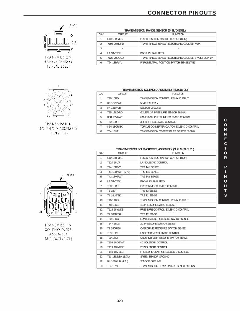
TRANSMISSION RANGE SENSOR (5.9L/DIESEL)CAV CIRCUIT FUNCTION
1 L10 18BR/LG FUSED IGNITION SWITCH OUTPUT (RUN)
2 Y193 20YL/RD TRANS RANGE SENSOR ELECTRONIC CLUSTER MUX
3 - -
4 L1 18VT/BK BACKUP LAMP FEED
5 Y128 20DG/GY TRANS RANGE SENSOR ELECTRONIC CLUSTER 5 VOLT SUPPLY
6 T24 18BR/YL PARK/NEUTRAL POSITION SWITCH SENSE (T41)
TRANSMISSION SOLENOID ASSEMBLY (5.9L/8.0L)CAV CIRCUIT FUNCTION
1 T16 16RD TRANSMISSION CONTROL RELAY OUTPUT
2 K6 18VT/WT 5 VOLT SUPPLY
3 K4 18BK/LB SENSOR GROUND
4 T25 18LG/RD GOVERNOR PRESSURE SENSOR SIGNAL
5 K88 18VT/WT GOVERNOR PRESSURE SOLENOID CONTROL
6 T60 18BR 3-4 SHIFT SOLENOID CONTROL
7 K54 18OR/BK TORQUE CONVERTER CLUTCH SOLENOID CONTROL
8 T54 18VT TRANSMISSION TEMPERATURE SENSOR SIGNAL
TRANSMISSION SOLENOID/TRS ASSEMBLY (3.7L/4.7L/5.7L)CAV CIRCUIT FUNCTION
1 L10 18BR/LG FUSED IGNITION SWITCH OUTPUT (RUN)
2 T120 18LG LR SOLENOID CONTROL
3 T24 18BR/YL TRS T41 SENSE
4 T41 18BK/WT (5.7L) TRS T41 SENSE
5 T42 18VT/WT TRS T42 SENSE
6 L1 18VT/BK BACK-UP LAMP FEED
7 T60 18BR OVERDRIVE SOLENOID CONTROL
8 T3 18VT TRS T3 SENSE
9 T1 18LG/BK TRS T1 SENSE
10 T16 14RD TRANSMISSION CONTROL RELAY OUTPUT
11 T48 18DB 4C PRESSURE SWITCH SENSE
12 T118 18YL/DB PRESSURE CONTROL SOLENOID CONTROL
13 T4 18PK/OR TRS T2 SENSE
14 T50 18DG LOW/REVERSE PRESSURE SWITCH SENSE
15 T147 18LB 2C PRESSURE SWITCH SENSE
16 T9 18OR/BK OVERDRIVE PRESSURE SWITCH SENSE
17 T59 18PK UNDERDRIVE SOLENOID CONTROL
18 T29 18GY UNDERDRIVE PRESSURE SWITCH SENSE
19 T159 18DG/WT 4C SOLENOID CONTROL
20 T119 18WT/DB 2C SOLENOID CONTROL
21 T140 18VT/LG PRESSURE CONTROL SOLENOID CONTROL
22 T13 18DB/BK (5.7L) SPEED SENSOR GROUND
22 K4 18BK/LB (4.7L) SENSOR GROUND
23 T54 18VT TRANSMISSION TEMPERATURE SENSOR SIGNAL
CONNECTOR
PINOUTS
329
CONNECTOR PINOUTS
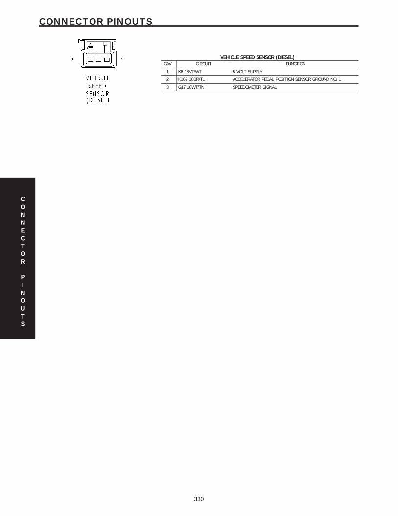
VEHICLE SPEED SENSOR (DIESEL)CAV CIRCUIT FUNCTION
1 K6 18VT/WT 5 VOLT SUPPLY
2 K167 18BR/TL ACCELERATOR PEDAL POSITION SENSOR GROUND NO. 1
3 G17 18WT/TN SPEEDOMETER SIGNAL
CONNECTOR
PINOUTS
330
CONNECTOR PINOUTS
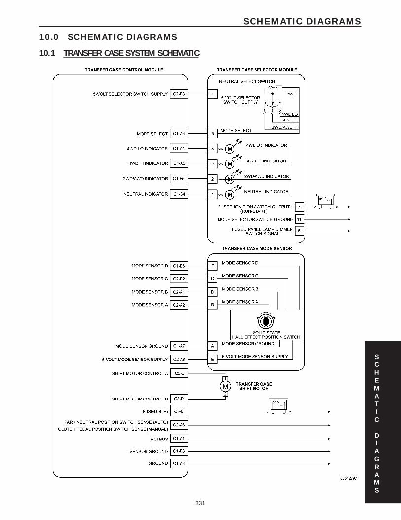
10.0 SCHEMATIC DIAGRAMS
10.1 TRANSFER CASE SYSTEM SCHEMATIC
SCHEMATIC
DIAGRAMS
331
SCHEMATIC DIAGRAMS
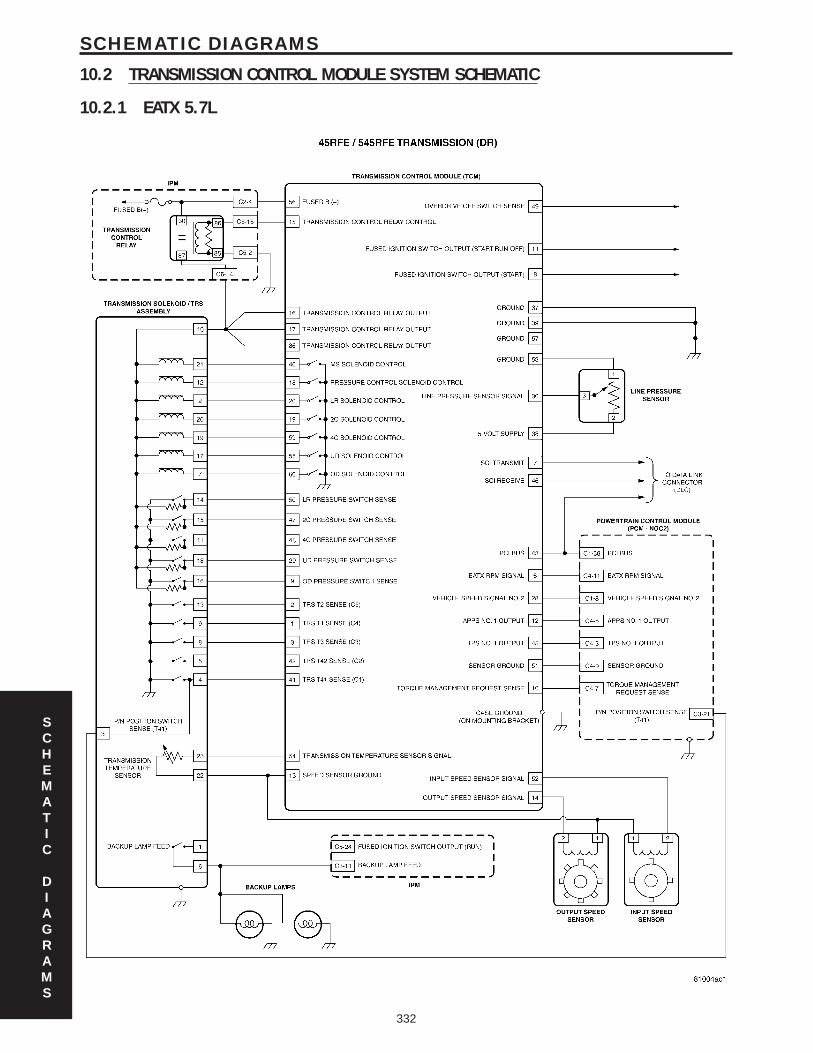
10.2 TRANSMISSION CONTROL MODULE SYSTEM SCHEMATIC
10.2.1 EATX 5.7L
SCHEMATIC
DIAGRAMS
332
SCHEMATIC DIAGRAMS
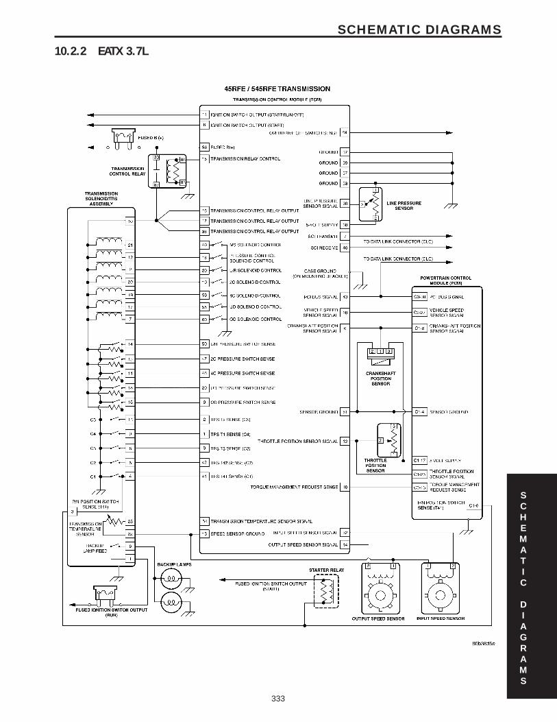
10.2.2 EATX 3.7L
SCHEMATIC
DIAGRAMS
333
SCHEMATIC DIAGRAMS

NOTES
334
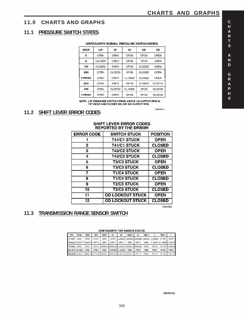
11.0 CHARTS AND GRAPHS
11.1 PRESSURE SWITCH STATES
11.2 SHIFT LEVER ERROR CODES
11.3 TRANSMISSION RANGE SENSOR SWITCH
CHARTS
AND
GRAPHS
335
CHARTS AND GRAPHS

NOTES
336