Embed Size (px)
Citation preview

EFFECTS OF SWITCH LEAKAGES UPON NIMBUS-7 SMMR CALIBRATION
Daesoo Han
NASA Goddard Space Flight Center
Greenbelt, Maryland
Seung T. Kim
ST Systems Corporation
9701 J Philadelphia Way
Lanham, Maryland
June 1988
I_ASA-CH-180792} EI_]_C_S Gt -_&I_CH LEAKAGES
CSCL 22_
G3/18
_89-1_115
GODDARD SPACE FLIGHT CENTER
Greenbelt, Maryland
https://ntrs.nasa.gov/search.jsp?R=19890000744 2018-07-22T13:01:54+00:00Z

TABLE OF CONTENTS
a_a
INTRODUCTION ............................................. 1
CALIBRATION EQUATIONS .................................... 3
2.1 Channels with a polarization selector switch ........ 3
2.2 37 GHz channels ..................................... Ii
CURRENT CALIBRATION EQUATIONS ............................ 15
FURTHER DISCUSSION ....................................... 15
REFERENCES ............................................... 16
PREOEDRqG PAGE BLANK NOT WfLMED
iii

1.0 INTRODUCTION
The Nimbus-7 Scanning Multichannel Microwave Radiometer (SMMR)consists of six conventional Dicke-type radiometers: two, operatingat 37 GHz, measuring simultaneously the horizontal and verticalpolarizations; the other four, operating at 6.6, 10.7, 18, and 21GHz, measuring the two orthogonal polarizations alternately during ascan. Thus the SMMRprovides ten data channels, corresponding to
two orthogonal polarizations at five frequencies. A description of
the SMMR instrument was given by Gloersen and Barath (1977). Only
those instrument characteristics that sre relevant to this study
will be pointed out in this and later sections.
All six radiometers share a single offset parabolic reflector.
While the reflector scans 25 ° to the left and right of the satellite
flight direction, the multi-frequency feed horn (MFFH) remains
fixed. This configuration of the fixed MFFH relative to the
scanning reflector introduces a polarization mixing in the measured
signal, which would be given by Eq. (i) below, if the instrument
were perfect:
iTx)<cos20sin0)<H)T_ sin=_ cos=_ V ,
(1)
where Tx and Tz are measured radiances for horizontal and vertical
channels, respectively, H and V are horizontal and vertical
components of the surface radiance, respectively, and _ is the scan
angle. In Eq. (i), Tx and Ty are symmetric about the scan angle
_=0. However, as noticed by Gloersen et al. (1980) and Gloersen
(1983), the measured radiances are not symmetric about scan angle
_=0, but the whole shape is shifted as shown in Fig. i. The cause
of the shift was not well understood at that time. So, to
compensate for the shift, "offset angles", S_ and 6y were
empirically introduced in the following manner:
cos=(¢ + v ,(2)
where the values of 6_ and By are determined from the measured data
using regression technique.
The radiometers operating at lower four frequencies utilize
polarization selector switches for measuring one of the two
polarizations. There are leakages in a polarization selector
switch, which is about 1% of the total input power. In Section
2.1, it is shown that the leakages, though small, cause interference
between the signal to be measured and the one to be suppressed, thus
generating a term which is not symmetric about _=0. There is also
additional mixing between the two polarizations that arises from the
leakages at other switches. The same procedure is followed in
Section 2.2 to derive a new set of calibration equations for the 37
GHz radiometers which do not need a polarization selector switch.

oK
W
I.UI-
ZZU,II--Z,<
160
155
150
145
I I I i I
-25 - 15 -5 5 15 25
,i:t /105
100
6.6GHzH
I l I I I
-25 -15 -5 5 15 25
SCAN ANGLE (DEGREE)
FIGURE i. Averaged antenna temperatutes for 6.6 GHz horizontal and
verticalchannels versus scan angle. For averaging, one
month of November, 1978 data over Pacific ocean are used.

In Section 3, it is shown that the current calibration equations canbe derived from the new ones if switch leakages are ignored. In thelast section, methods to analyze in-flight data to obtain"absolutely calibrated" radiances are briefly discussed.
2.0 CALIBRATION EQUATIONS
The basic calibration scheme of the SMMRutilizes a two-pointreference signal system consisting of an ambient RF termination anda horn antenna viewing deep space with known brightnesstemperatures. However the situation gets complicated because theferrite switches that selects particular signal paths have non-negligible leakages. The measured radiances of the cold referencetargets have additional leakage-dependent components that aredifferent from those form the warm reference targets. Theseleakage-induced biases are also different from those coming from thepaths chosen for measuring the surface radiances. Therfore it isnecessary to treat individual signal paths separately to identifyand compensate for the leakage-dependent bias terms.
In Subsection 2.1, a set of new calibration equations arederived for the the radiometers operating at lower four frequenciesthat utilize ferrite switches to select one of the two orthogonallypolarized radiances. Separate treatment is provided in Subsection2.2 for the two radiometers operating at 37 GHz - one for each ofthe two orthogonal polarizations.
2.1 Channels with a polarization selector switch
A schematic diagram of the RF components for a typicalradiometer, which provides two orthogonal polarization channelsoperating at a common frequency, is shown in Fig. 2. In addition tothe familiar modulator (or Dicke) switch, there are three latchingferrite switches: the sky/ambient switch (c) which selects a signalfrom either a sky horn or an ambient load; the polarization selectorswitch (p) which selects either a horizontally or verticallypolarized signal from the multi-frequency feed horn; the cal/sigswitch (s) which selects a signal from either switch c or p. Thesethree switches, when suitably set, provide four distinct signalpaths to the modulator switch input port marked I in Fig. 2; twopaths for cold and warm reference signals and another two paths forhorizontally and vertically polarized radiances.
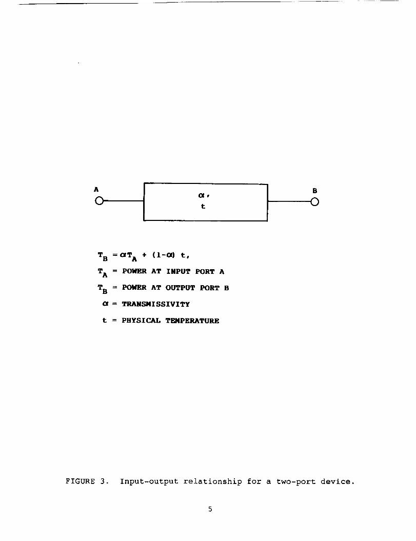
In the following we will derive a relationship between thetarget temperature and the power at port I by piecing together theinput-output relationships for individual RF components along eachsignal path. By way of introducing notations, we write down genericinput-output relationships for two- and three-port devices. For atwo-port device, (with input port A and output port B, as shown inFig. 3), the output power, TB is given by
TB = _TA + (l-_)t, (3)
where TA is the input power, _ is the transmissivity of the device,

LD HORN C, SKY/AMBIENT
SNITCH
se CAL/SIGSWITCH
ANT HORN
ERT. WG
ORIZ. I@G
REF TEMP LOAD
P, POLARIZATION
SEI-RCTOR SNITCH
TO DET,
CORRELATOR,
INTEGRATOR
A/D CONVERTOR
FIGURE 2.Schematic diagram of RF components of the Nimbus-7 SMMR.
- except for the 37 Ghz channels.
A
Ot
B
O
T B =_T A + (I-_) t,
T A = POWER AT INPOT PORT A
T B = POWER AT OUTPUT PORT B
= TRANSMI SSIVITY
t = PHYSICAL TEMPERATURE
FIGURE 3. Input-output relationship for a two-port device.

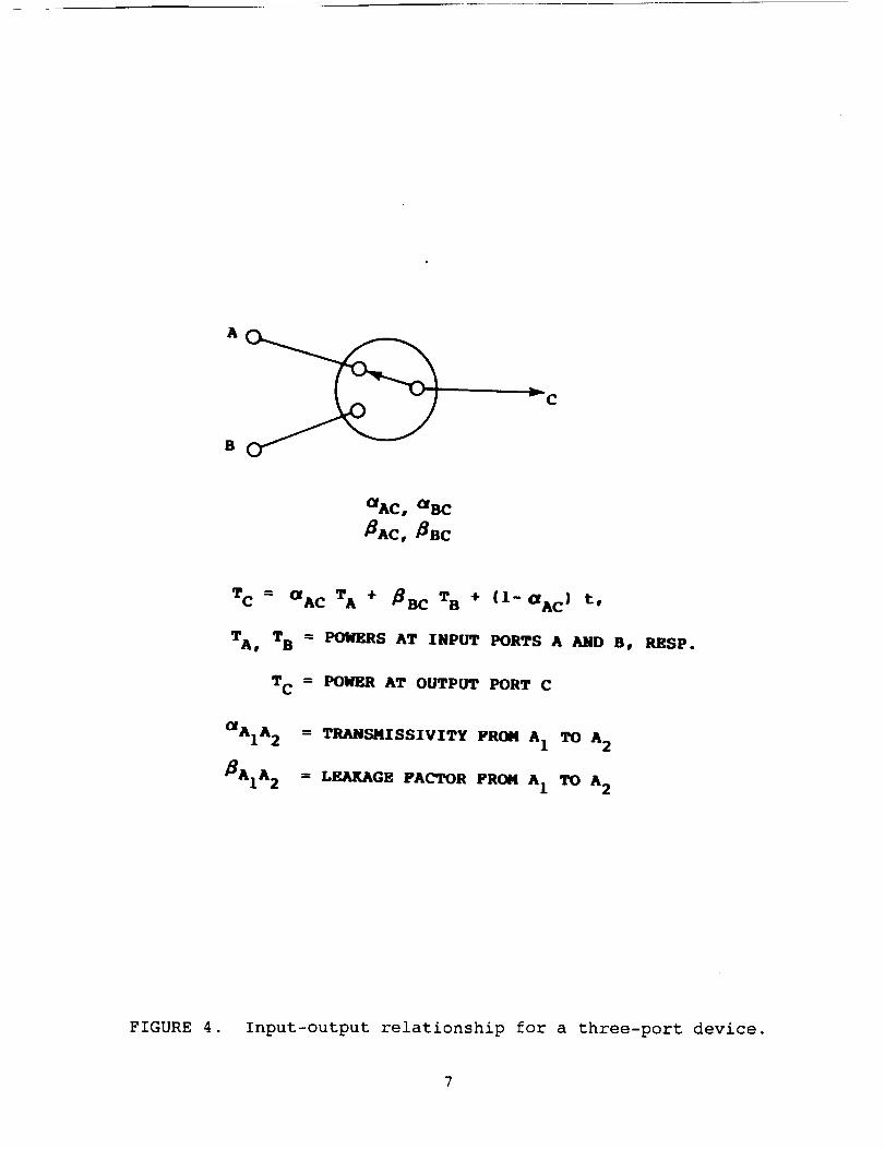
and t is the physical temperature . For a ferrite switch x (=p,c,s)with input ports A and B and output port C, the output power, Tc,when port A is selected (see Fig. 4), is assumed to be given by
Tc = s_cTA + _cT_ + (l-_c)t, (4)
where TA and Ts are input powers at ports A and B, respectively,
_c is the transmissivity from A to C, _xmc is the leakage factor
from B to C, and t is the device's physical temperature.
We start with microwave radiation emitted from the earth's
surface, which may be expressed in terms of electric field as
E = < Ex exp(iwt) 1Ey exp(iwt + i_)
(5)
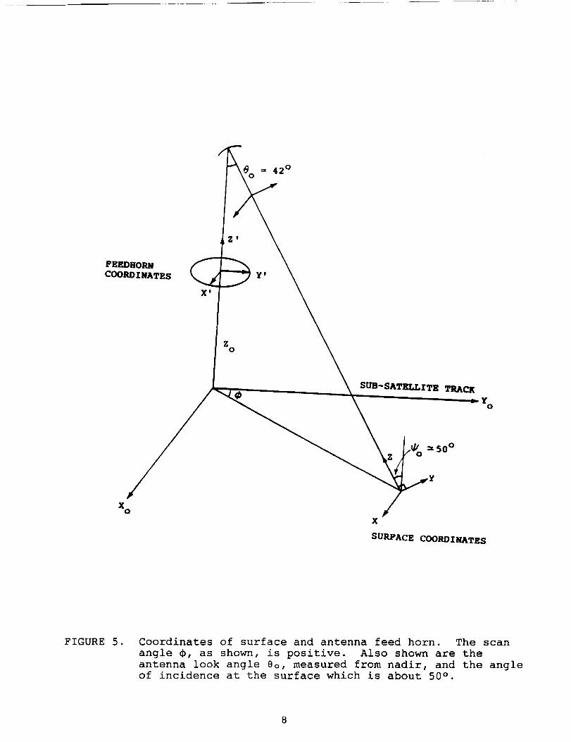
where Ex and Ey are the horizontal and vertical components of the
electric field defined on the coordinate system connecting the earth
surface and the antenna (Fig. 5), w is the microwave frequency, and
is the phase difference which is assumed to have any value between
0 and 2K with equal probability. The electric field, E is reflected
by the reflector to the feed horn. Since the feed horn coordinates
are rotated relative to the scanning reflector by an amount of scan
angle _, the two orthogonal components Exx and Ely selected by the
horn are given by
cos _ sin _ >El = E. (6)-sin _ cos
The two orthogonal components are routed separately to switch p via
waveguides or coaxial cables, undergoing attenuation by a factor of
g_ and g_, respectively. Though prelaunch test results suggested
that the switch leakages from an unselected input port to the output
port should be negligible, the effective leakages may not be
negligible, when mismatched components are attached to the ports.
We denote by kx_ the magnitude of the blocked portion of the
horizontal polarization component, and by k=_ the leaked portion
from the vertical polarization added to the horizontal component;
and similarly for kxy and k=y. We note that these quantities are
related to the transmissivities and leakage factors of switch p as
follows:
_u_ = (i - klx) =,
a_v_ = (i - kly) =,
_p_A = k2_ 2 ,
_pVA : k2x 2 •
Immediately after a polarization is selected, the electric field,E2
would be given by
TC -- aAC TA + _BC TB + (I-aAC) t,
TA, T B
TC
aAil 2
B^I^ 2
= POKERS AT INPUT PORTS A AND B, RESP.
= POWER AT OUTPUT PORT C
= TRANSMISSIVITY FROM AI
= LEAKAGE FACTOR FROM A I
TO A 2
A 2
FIGURE 4. Input-output relationship for a three-port device.
7
42 °
FEEDHORM
COORD INATES Y '
X $
Zo
SUB-SATELLITE TRACK
Yo
=50 °
Xo
X
SURFACE COORDINATES
FIGURE 5. Coordinates of surface and antenna feed horn. The scan
angle _, as shown, is positive. Also shown are the
antenna look angle 8o, measured from nadir, and the angleof incidence at the surface which is about 50 ° .

(Ikx k2xexpie)(gx0)El7k2y exp(iSy) i - kl_ 0 g_
where 8x and 8_ are phase differences and Ex is given by Eq. (6).
The power at the output port of switch p, solely due to surface
radiation, is given by
Tx = < (Re E2_) = >=.n, (8.a)
T_ = < (Re E=y) = >_,n, (8.b)
where < >=.n denotes the averaging operation over t and _. From
Eqs. (5) through (8), one obtains
T_ = A_[H cos=(_+6_) + V sin=(_+6_)] + Bx(H + V), (9.a)
T_ = A_[H sin=(_+6_) + V cos=(_+_y)] + B_(H + V), (9.b)
where
H = E_ =,
V = Ey =,
A_ = {[g_=(l-k_x) = + g_=k=_=] = [2g_gy(l-k_x)k=xsinSx]=} Iz=
Bx = 0.5 [gx=(l-k1_) = + gy=k=_ = - A_],
Ay = {[gy=(l-k1_) = + g_=k=_=] = - [2gyg_(l-kx_)k=ysin8y]=} x/=,
By = 0.5 [gy2(l-kxy) 2 + g_=k=_ - Ay],
tan(26_) = 2g_g_(l-kxx)k=_cosS_/[g_=(l-klx) = - gy=k=x=],
tan(2S_) = 2g_g_(l-kly)k=ycosSy/[gz=(l-k1_) = - g_=k=y=].
We denote by T_.. and T_.v the powers at port A when switch p
selects port H and V, respectively. Then T_.H (T_.v) is the sum of
Tx (Ty) and Q_.. (QA.v) which are noise powers added incoherently
along the respective signal paths from the feed horn to port A:
TA.. = T_ + QA.., (10.a)
TA.v = Ty + QA.V, (10.b)
where Q_.. and Q_.v, computed using Eqs. (3) and (4), are givenbelow:
QA._ = o_u_[_.w_(l-_._)t_ + (l-_._)t_]
+ _pv_[e._v(l--e.hv)t.h + (l-_._)t._v]
+ (l-c_u_) t.,
9

QA.v = C_pVA[CZawv(l--_ahv)tah + (l--_a_v)ta_v]+ _p_U_[_a_(l--_h_)t_h + (l--_w_)t_w_]+ (l--OhpvA)th,
where t_h, t_, ta_v, and t_ are physical temperatures of antennahorn, horizontal wave guide, vertical wave guide, and switchassembly, respectively, and _hH(v), _wH(v) are transmissivities ofthe antenna horn and wave guide for the horizontally (vertically)polarized signal path. From Eqs. (9) and (i0), one obtains
V TA.v - QA.V(Ii)
where R, which we may term the generalized polarization rotationmatrix, is given by
R = (A_ cos=(_+Gx) + Bx
\ Ay sin2(_+Sy) + By
A_ sin=(_+_) + B_ -_
/Ay COS=(_+Gy) + By
(12)
Equation (ii), which expresses the surface brightness in terms of
the powers at port A for two antenna paths, is one of our two basic
sets of calibration equations.
In the remainder of this section, we derive the second basic
set of equations. The power at port K of switch c is given by
T_ = _[_:_Tc + (l-_:_)t:_] + (l-_=w)t=_, (13)
where _=_ and _ are the transmissivities of the cold horn and wave
guide, respectively, and t_h and t=_ are the physical temperatures
of the cold horn and wave guide, respectively.
We denote by Tx.., Tx.v, Tz.c, Tz.w the powers at port I for
the four distinct signal paths designated by H, V, C, and W, each of
which is defined by a set of swich settings of switches c, p, and s
as follows:
Path H - Switch settings; p on H, c on L, s on A
Path V - Switch settings; p on V, c on L, s on A
Path C - Switch settings; p on H, c on K, s on C
Path W - Switch settings; p on V, c on L, s on C
Applying the input-output relationship of Eq. (4) to each switch
along a chosen path, one obtains
(14)
Tx.v = _._zTA.v + _.cx(t_+_cT_) + (l-_._x)t_, (15)
Tz.c = _.c=(_cT_ + _==cth + (l-_=_c)th)
+ _._xT_._ + (l-_.c=)t_, (16)
l0

T_,w = e.cz (th + 6cKcTK) + _.A_TA,v+ ( l--_.cx)th. (17)
The integrate and dump output of the radiometer, denoted by C,
is given in terms of the input power, Tz at port I, as follows:
C = G (Tx - th) + O, (18)
where G is the radiometer gain and 0 an offset added to make C
increase with T=. Both G and 0 are assumed to remain constant from
one end of scan to the other, and are effectively eliminated from
calibration equations through introduction of normalized counts, NHand Nv defined below:
N. _ (CA.. - Cw)/(Cc - Cw), (19.a)
Nv m (CA,v - Cw)/(Cc - Cw), (19.b)
where CA,H, CA,v, Cc, and Cw are the radiometer outputs
corresponding to the four paths H, V, C, and W, respectively.
Substituting Eq. (18) into Eqs. (19.a) and (19.b), one obtains
NH = (Tx,. - Tx,w)/(Tx,c - Tz,w), (20.a)
Nv = (T_,v - Tz,w)/(Tz,c - Tx,w). (20.b)
Substituting Eqs (14) through (17) into Eqs. (20.a) and (20.b), we
obtain the second basic set of calibration equations given below:
TA,_ = {[-(_.Ax - _.A_)D - _._zC]N_
+ _.Ax(C-D)Nv + .A=c}Ir, (21.a)
TA,v = {(--_.AzD + _.A=C)Nv - (_.A=C)N_
+ _.A_C}/F, (21.b)
where
C = (_.cx - _.cx)_KcT_ + (e.Ax - _.cx)th,
D = - e.cz(_=_c - _=Kc)T_ + _.c_(_=_c - _==c)th,
F = (_._x - _.Az)C_-_z + _._z(Nv - N_)].
Using measured quantities, N_ and Nv, one can compute from Eq.
(21), TA,_ and TA,v, and then substitute them into Eq. (ii) to
obtain surface radiances. Thus, Eqs. (ii) and (21) constitute a new
set of calibration equations for the Nimbus-7 SMMR.
2.2 37 GHz channels
A schematic diagram of the RF components of a 37 GHz radiometer
is shown in Fig. 6. The polarization selector switch shown in Fig.
2 is absent in Fig. 6 because a separate radiometer is utilized for
measuring each of two orthogonally polarized radiances. Thus
ll

polarization mixing is solely due to the rotation of the reflectorrelative to the fixed MFFH. The reasoning of the previoussubsection may be adapted here to derive the calibration equationsfor the 37 GHz channels.
Setting klx, kly, k=x, k=y to zero, one obtains from Eq. (9)the following:
Tx = Ax (H cos=_ + V sin2_), (22.a)
T_ = A_ (H sin=_ + V cos2¢), (22.b)
where
a_c = gx2f
Ay = gy2
We denote by TH the power at the input port A of the cal/sig
switch (see Fig. 6). Similarly for Tv. Then T_ (Tv) is, as before,
the sum of Tx (Ty) and Q. (Qv):
T. = Tx + QH, (23.a)
Tv = Ty + Qv, (23.b)
where Q. and Qv are obtained from QA,_ and QA,v of previous
subsection by setting _u_ = _vA = i, and _pVA = _u_ = 0:
Q_ = _a_(l-_h_)t_h + (l-_a_H)t_,
Qv = _wv(l-_,hv)t_h + (l-_.wv)ta_v,
where the symbols have the same meanings as in the previoussubsection.
From Eqs.(22) and (23), one obtains
(H)R3(TH0)V Tv - Qv ,
(24)
where R3v is gotten from Eq. (12) by setting S_ = Sy = 0, and B_ =
By = 0:
A_ cos=_ Ax sin2_ )-_R3v = (25)
ay sin=_ A_ COS2_
In deriving second basic set of equations, we focus our
attention on the horizontal radiometer only; the corresponding set
of equations for the vertical polarization radiometer will have the
same form as that for the horizontal counterpart. The power at port
K of swtich c, denoted by Tx_, is given by
12

C, SKY/AMBIENT
SWI TCHCOLD HORN
_ WAVE-GUIDE
REFLECTOR
ANTENNA
HORN
WAVEGUIDE
s , _M-/SIGSWITCH
_ REFERENCE
TEMP LOAD
_ ISOLATOR
fDETEC_q)R
CO .RTeR
L.O.: Local Oscillator
FIGURE 6. Schematic diagram of the RF components of Nimbus-7 SMMR
- 37 GHz channels.

Tix = _law[_chTc + (l--_ah)t=h] + (l--e1=w)t1=w, (26)
where _=h and _x_w are the transmissivities of the cold horn and the
waveguide, respectively, and t_h and tx=w are the physical
temperatures of the cold horn and the waveguide, respectively. The
subscripts preceded by 1 (or 2) refer to the variables for the H (or
V) polarization radiometers, respectively.
We define Tz._, T_.c, and T_.w as follows:
Tz._ - the power at port I, when s selects A and c selects L;
Tz.c - the power at port I, when s selects C and c selects K;
Tx.w - the power at port I, when s selects C and c selects L.
Then applying the input-output relationship of Eq. (4) to each
switch for a chosen configuration, one obtains
Tx.H = _I.AxT_ + _l.c=(tlh+_1=KcTiK)
+ (l--_X.kx)t_h, (27)
Tx.c = _1.c=[_xaxcTx_ + _xc=ct_h + (I--_X_Kc)tXh]
+ _I.A=T_ + (I--_X.cI)tXh, (28)
Tx.w = _x.cz(txh +_cTx_) + _x._zT_
+ (l--Ux.c=)t_h. (29)
Defining the normalized count, N. in a manner similar to Eq.
(19.a), and applying Eq. (18), one obtains
N_ = (Tx._ - Tx.w)/(Tx.c - Tz.w), (30)
Substituting Eqs. (27) through ((29) into Eq. (30), on obtains
T_ = A. + B_ N_, (31)
where
An = (_1._z - _.cx)(t_h + _xc_cT_K)IF_,
B. = _x.cx[(_xc_c - _X=Lc)t=h -- (_x=xc -- _x=_c)Tx_]/F.,
Similarly for the 37 GHz vertical polarization radiometer, one
obtains
Tv = Av + Bv Nv, (32)
where
Av = (_=.AX -- _=.cx)(t=h + _=_KcT=_)/Fv,
14

Eqs. (24), (31), and (32) constitute the basic calibration
equations for the 37 GHz radiometers of the new model - substituting
Eqs. (31) and (32) into Eq. (24), we get a relationship that
expresses surface radiances in terms of measured quantities.
3.0 CURRENT CALIBRATION EQUATIONS
The calibration equations currently in use for for the Nimbus-7
SMMR data production can be derived from the results of Section 2 if
we reinstate the assumption that switch leakages are negligible. In
this section we will derive current calibration equations for only
those that utilize polarization selector switches since the
derivation of the calibration equations for the 37 GHz radiometers
is rather straightforward.
Setting all the leakage factors appearing in Eqs. (21.a) and
(21.b) to zero, we obtain simplified expressions for TA,H and TA,v:
TA,H = th + _o(TK - th)N_, (33.a)
TA,V = t_ + _o(TK -- th)Nv, (33.b)
where So = _.C=_KC/_.A=, and Tx is given by Eq. (13).
Polarization rotation, which accounts for not only the antenna
scan but also the polarization mixing at switch p, is effected
empirically by introducing "offset angles", Sx and Sy into the
polarization rotation matrix given below:
R' = (c°s=(_+_x)
\ sin=(_+Sy)sin=(_+5_) )-xcos=(¢+Sy)
(34)
The matrix, R', when compared with R (Eq. (12)), is seen to account
for the effect of switch leakages (in switch p) only partially in
that the factors A_ and A_ and biases B_ and By in R are not present
in R'. Replacing R of Eq. (ii) by R' and substituting into it T_,,
and TA,v of Eqs. (33.a) and (33.b), we obtain the current
calibration equations given below:
I"l.Ith°A thNH1V t_ - Q'_,v + Czo(TK - th)Nv ,
(35)
where Q'A,, and Q'A,v proceed from Q_,_ and QA,v by setting _pv_ and
_,A to zero.
4.0 FURTHER DISCUSSION
A new calibration scheme for the Nimbus-7 SMMR is studied in
this report. The apparent deviation of the measured radiances from
the anticipated symmetry in scan angle is explained by this model
15

through including leakages at the polarization selector switch.This feature, asymmetry in scan angle, is caused by the interferencebetween horizontally and vertically polarized fields which, havingtraveled different paths and merging at the polarization selectorswitch, have path differences comparable with the wavelengths of themicrowave radiation.
Another important aspect of the new calibration model is that
it offers a possibility of deriving "absolutely calibrated"
radiances, which are necessary to test and validate models for
surface and atmosphere. It is clear from Eqs. (II) and (21) that
the values of transmissivities and leakage factors must be known
prior to implementing the new model in the SMMR data processing.
Only a few transmissivities had been determined before launch, and
none of leakage factors have been measured on the assembled
instrument. Attempts to determine some leakage factors using in-
flight data were unsuccessful because of the difficulties of
estimating the surface brightness, H and V of Eq. (ii), to the
accuracy required for such an analysis. Without means of obtaining
acceptable values of _'s and _'s, it appears impossible to derive
absolutely calibrated brightness temperatures from in-flght
measurements alone. However, if ground measurements are made, which
are colocated in space and time with the SMMR measurements, and a
good atmospheric model is available, then it is possible to achieve
absolute calibration.
In the absence of the desired ground measurements, the new
calibration equations can still be useful in understanding the
evolutionary nature of the aging instrument's problems. Instead of
attempting to determine _'s and _'s, we start with a set of
preassigned values of _'s and _'s and compute from measured
quantities, N. and Nv, the surface brightness temperatures in
accordance with Eqs. (ii) and (21). The new brightness temperatures
can be scrutinized whether their long-term behavior is satisfactory
or not, or may be used to derive geophysical parameters whose
validity can be tested against ground measurements. If comparisons
show that the new brightness temperatures produce better results
than the current ones, we may adopt the presumed values of _'s and
_'s as representing the instrument's status. In this manner, we may
identify and assess the cause(s) of some of the instrument's
problems.
REFERENCES
Gloersen, P., 1983: Calibration of the Nimbus-7 SMMR: II
Polarization mixing corrections, TM R4976, NASA/Goddard Space
Flight Center, Greenbelt, Maryland.
Gloersen, P., and F. T. Barath, 1977: A scanning multichannel
microwave radiometer for Nimbus-G and SeaSat-A, IEEE J. Oceanic
_Jl_, OE-2, 172-178
Gloersen, P., D. J. Cavalieri, and H. V. Soule, 1980: An alternate
algorithm for correction of the scanning multichannel microwave
16

radiometer polarization radiances using Nimbus-7 observed data,_, NASA/Goddard Space Flight Center, Greenbelt,Maryland.
17

Report Documentation PageNalOnal Aeror_utcs andSoace AOn"_,_sfr aloq
1. Report No.
4. Title and Subtitle
Effects of Switch LeakagesSMMR Calibration
7. Author(s)
Daesoo Han and Seung T. Kim
2. Government Accession No.
Upon Nimbus-7
9. Performing Organization Name and Address
Goddard Space Flight CenterGreenbelt, MD 20771
12. Sponsoring Agency Name and Address
National Aeronautics and
Washington, DC 20546Space Administration
3. Recipient's Catalog No.
5. Report Date
June 1988
6. Performing Organization Code
636
8. Performing Organization Report No.
10. Work Unit No.
665-10-70
11. Contract or Grant No.
NAS5-29386
13. Type of Report and Period Covered
Technical Memorandum
14. Sponsoring Agency Code
15. Supplementary Notes
Daesoo Han: Goddard Space Flight CenterSeung T. Kim: ST Systems Corporation
16. Abstract
A calibration model for the Nimbus-7 Scanning Multichannel Microwave Radiometer
(SMMR) is studied. This model not only removes major drawbacks of the current
calibration model but also helps us understand the performance degradation of the
aging instrument. The current Nimbus-7 SMMR calibration algorithm was derived
without considering the interference effect between the two orthogonally polarized
signals merging at a ferrite polarization selector switch. The resultingcalibrated brightness temperatures, considered as a function of scan angle _, are
not symmetric around _I = O. However, neither the origin of the asymmetry nor themanner in which the two orthogonal components are mixed has been fully understood.
The new calibration model proposed in this paper incorporates all the leakage
factors associated with the ferrite switches along the signal paths. The resulting
calibration equations clarify how the orthogonal components of surface brightness
are coupled at radiometers. As a consequence, the origin of the asymmetry is
clearly identified and explained. In addition, the feasibility of "absolute
calibration" using in-orbit data is discussed.
17. Key Words (Suggested by Author(s))
Scanning Multichannel MicrowaveRadiometer, Calibration, Switch
Leakage
18. Distribution Statement
Unclassified -- Unlimited
Subject Category /_
19. Security Classif. (of this report)
Unclassified
20. Security C)assif. (of this page)
Unclassified
21. No. of pages
17
22. Price
NASA FORM 1626 OCT 86

![Classification of Merged AVHRR and SMMR Arctic Data with ... · Classification of Merged AVHRR and SMMR Arctic Data with Neural Networks J. Key, ]. A. Maslanik, and A. ]. Schweiger](https://img.pdfslide.us/doc/110x75/5ec493230b627b05912917e5/classification-of-merged-avhrr-and-smmr-arctic-data-with-classification-of-merged.jpg)