Embed Size (px)
Citation preview
605951
Table of Contents
November 2011
The information contained in this generic specification represents a part of Carlisle’s requirements for obtaining a roofing system warranty. Construction materials and practices, building siting and operation, climatic conditions, and other site-specific factors will have an impact on the performance of the roofing system. Carlisle recommends that the building owner retain a design professional to determine appropriate design measures to be taken in order to address these factors.
Basic Wind Speed Map ............................................................................................................... DR-01-11 Codes and Wind Speed .............................................................................................................. DR-02-11 Insulation Fastening Patterns ...................................................................................................... DR-05-11 Withdrawal Resistance Criteria ................................................................................................... DR-06-11 CRRC/LEED Information ............................................................................................................ DR-07-11 Wood Nailers and Securement Criteria ...................................................................................... DR-08-11 Considerations for Hail Design .................................................................................................... DR-09-11
Metal Edging ............................................................................................................................... DR-12-11
DR-01-11
ASCE 7 Basic Wind Speed Map
November 2011
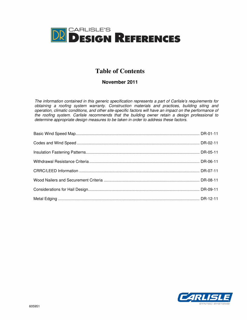
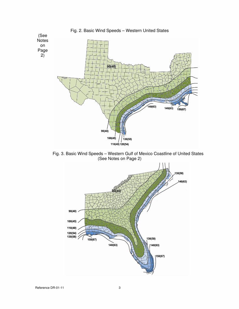
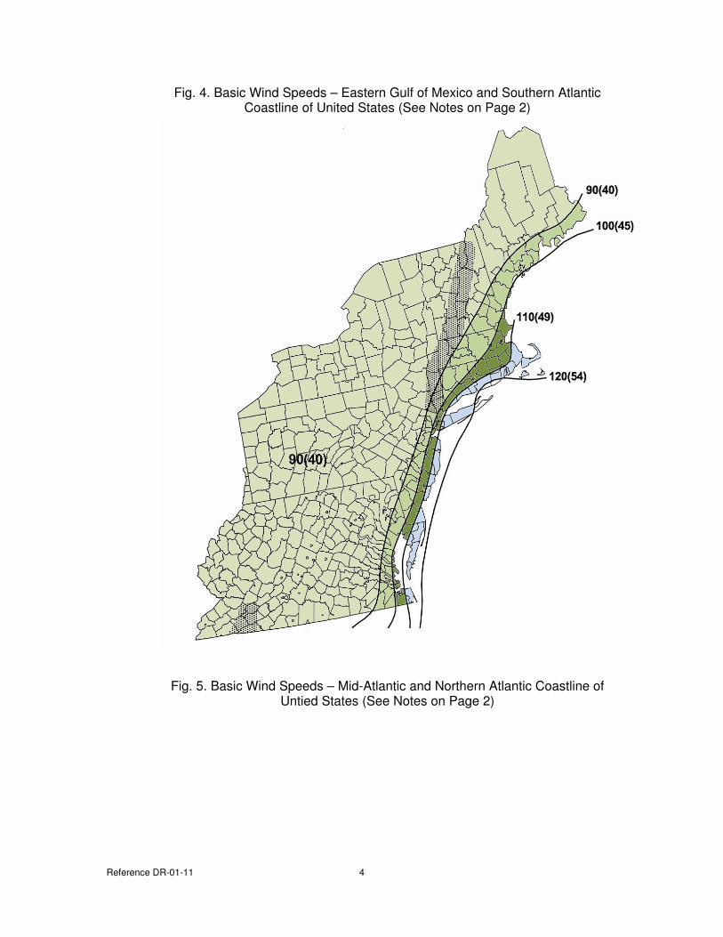
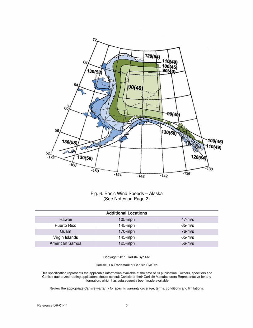
The maps included in this design reference section illustrate ground wind speeds as determined by American Society of Civil Engineers (ASCE). The data can be used when referencing the Carlisle Specification to determine an appropriate securement method as illustrated in the various Tables contained in the Warranty Section. This information is considered to be a minimum and Specifiers and Design Professionals may use such data at their own discretion.
Fig. 1 Basic Wind Speeds – Central & Eastern United States (See Notes on Page 2)
Reference DR-01-11 2
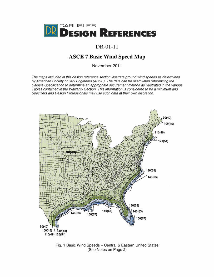
Notes associated to all maps:
= Special Wind Zone
1. Values are nominal design 3-second gust wind speeds in miles per hour at 33-ft above ground for Exposure C category.
2. Linear interpolation between wind contours is appropriate. 3. Islands and coastal areas outside the last contour shall use the last wind speed contour
of the coastal area. 4. Mountainous terrain, gorges, ocean promontories, and special wind regions shall be
examined for unusual wind conditions. Seek 50-yr MRI wind speed values from local building officials. As a minimum, increase the wind speed values by 10%.
Reference DR-01-11 3
Fig. 2. Basic Wind Speeds – Western United States (See Notes
on Page
2)
Fig. 3. Basic Wind Speeds – Western Gulf of Mexico Coastline of United States (See Notes on Page 2)
Reference DR-01-11 4
Fig. 4. Basic Wind Speeds – Eastern Gulf of Mexico and Southern Atlantic Coastline of United States (See Notes on Page 2)
Fig. 5. Basic Wind Speeds – Mid-Atlantic and Northern Atlantic Coastline of Untied States (See Notes on Page 2)
Reference DR-01-11 5
Fig. 6. Basic Wind Speeds – Alaska (See Notes on Page 2)
Additional Locations
Hawaii 105-mph 47-m/s
Puerto Rico 145-mph 65-m/s
Guam 170-mph 76-m/s
Virgin Islands 145-mph 65-m/s
American Samoa 125-mph 56-m/s
Copyright 2011 Carlisle SynTec
Carlisle is a Trademark of Carlisle SynTec
This specification represents the applicable information available at the time of its publication. Owners, specifiers and Carlisle authorized roofing applicators should consult Carlisle or their Carlisle Manufacturers Representative for any
information, which has subsequently been made available.
Review the appropriate Carlisle warranty for specific warranty coverage, terms, conditions and limitations.
DR-02-11
Codes & Wind Design
November 2011
Documents sited herein may be subject to change without Carlisle’s knowledge. Building Owners and Design Professionals are advised to obtain the latest information from the originators of the individual documents.
The information contained represents guidelines to address possible requirements as part of the building specification as listed under the Quality Assurance or Performance Article. Carlisle recommends that the building owner retain a design professional to verify that these guidelines are appropriate.
Topics Page
Underwriters Laboratories – External Fire Test Criteria ................................................................................ 2 Underwriters Laboratories – Internal Fire Test Criteria ................................................................................. 3 Factory Mutual Global (FMG) Approval Testing Criteria ............................................................................... 5 Determining the Proper FMG Rating – FMG Property Loss Prevention Data Sheet 1-28 ............................ 7 Determining Perimeter and Corner Enhancements – FMG PLPDS 1-29 ..................................................... 8 ASCE 7 ....................................................................................................................................................... 11
Reference DR-02-11 2
UNDERWRITERS LABORATORIES
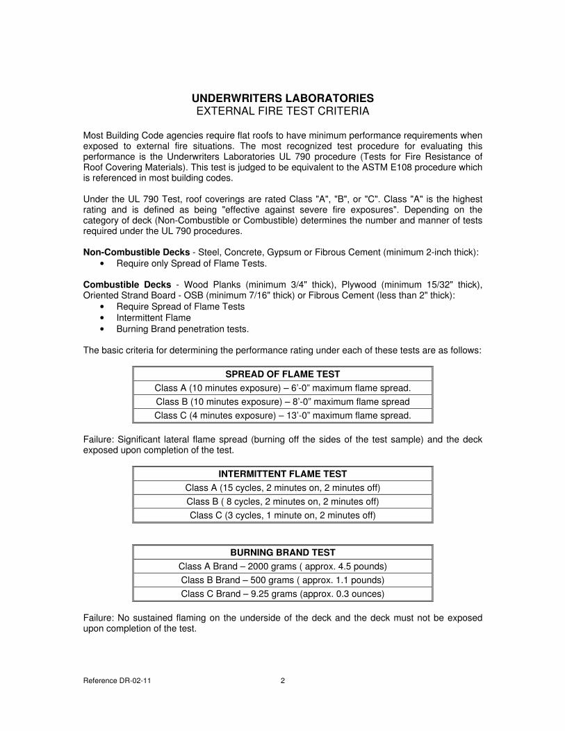
EXTERNAL FIRE TEST CRITERIA Most Building Code agencies require flat roofs to have minimum performance requirements when exposed to external fire situations. The most recognized test procedure for evaluating this performance is the Underwriters Laboratories UL 790 procedure (Tests for Fire Resistance of Roof Covering Materials). This test is judged to be equivalent to the ASTM E108 procedure which is referenced in most building codes. Under the UL 790 Test, roof coverings are rated Class "A", "B", or "C". Class "A" is the highest rating and is defined as being "effective against severe fire exposures". Depending on the category of deck (Non-Combustible or Combustible) determines the number and manner of tests required under the UL 790 procedures.
Non-Combustible Decks - Steel, Concrete, Gypsum or Fibrous Cement (minimum 2-inch thick):
• Require only Spread of Flame Tests.
Combustible Decks - Wood Planks (minimum 3/4" thick), Plywood (minimum 15/32" thick), Oriented Strand Board - OSB (minimum 7/16" thick) or Fibrous Cement (less than 2" thick):
• Require Spread of Flame Tests
• Intermittent Flame
• Burning Brand penetration tests. The basic criteria for determining the performance rating under each of these tests are as follows:
SPREAD OF FLAME TEST
Class A (10 minutes exposure) – 6’-0” maximum flame spread.
Class B (10 minutes exposure) – 8’-0” maximum flame spread
Class C (4 minutes exposure) – 13’-0” maximum flame spread.
Failure: Significant lateral flame spread (burning off the sides of the test sample) and the deck exposed upon completion of the test.
INTERMITTENT FLAME TEST
Class A (15 cycles, 2 minutes on, 2 minutes off)
Class B ( 8 cycles, 2 minutes on, 2 minutes off)
Class C (3 cycles, 1 minute on, 2 minutes off)
BURNING BRAND TEST
Class A Brand – 2000 grams ( approx. 4.5 pounds)
Class B Brand – 500 grams ( approx. 1.1 pounds)
Class C Brand – 9.25 grams (approx. 0.3 ounces)
Failure: No sustained flaming on the underside of the deck and the deck must not be exposed upon completion of the test.
Reference DR-02-11 3
It is important to remember that it is the complete assembly that is being evaluated including the deck type, insulation type and thickness, membrane type and surface treatment, if any. Mixing components which have not been tested together will void the rating. Assemblies classified for use over combustible decks may be used over non-combustible decks to achieve the same rating.
UNDERWRITERS LABORATORIES
INTERNAL FIRE RESISTANCE TEST CRITERIA AND RATINGS
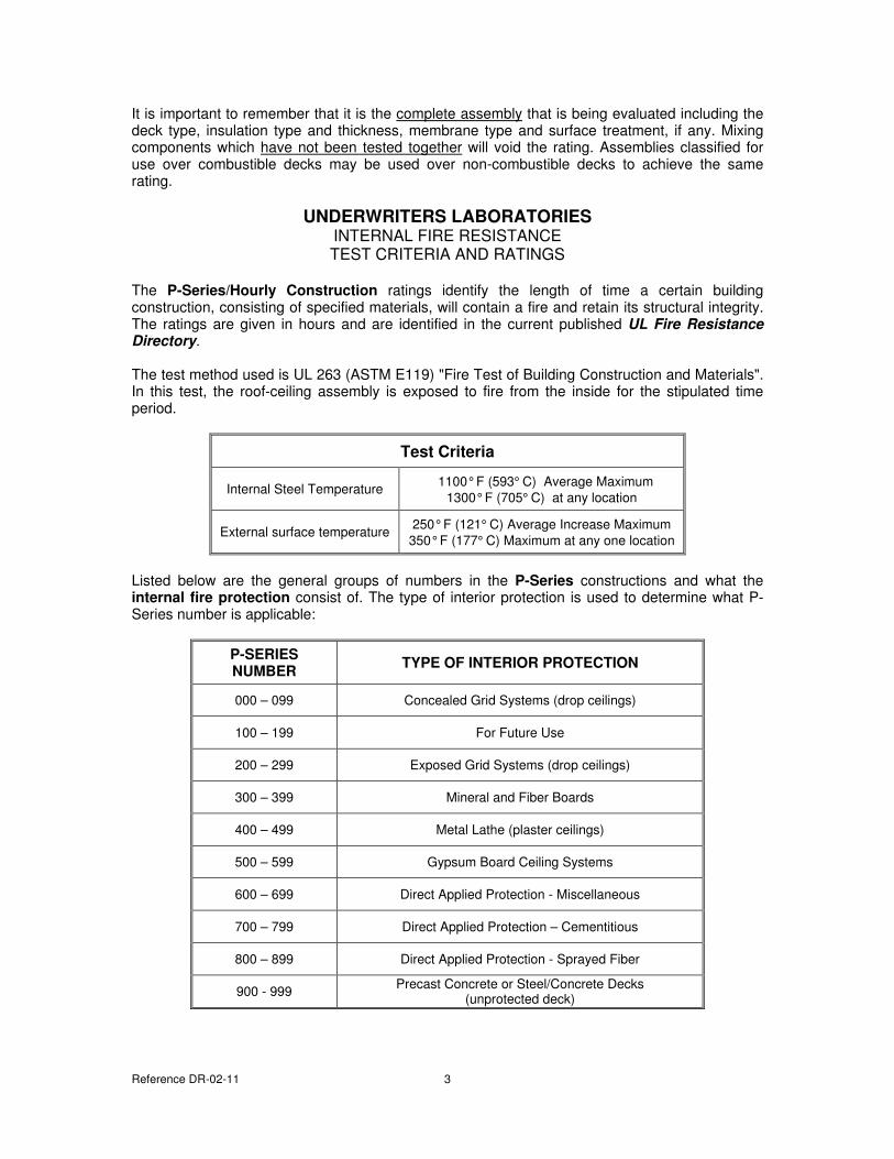
The P-Series/Hourly Construction ratings identify the length of time a certain building construction, consisting of specified materials, will contain a fire and retain its structural integrity. The ratings are given in hours and are identified in the current published UL Fire Resistance Directory. The test method used is UL 263 (ASTM E119) "Fire Test of Building Construction and Materials". In this test, the roof-ceiling assembly is exposed to fire from the inside for the stipulated time period.
Test Criteria
Internal Steel Temperature 1100° F (593° C) Average Maximum
1300° F (705° C) at any location
External surface temperature 250° F (121° C) Average Increase Maximum
350° F (177° C) Maximum at any one location
Listed below are the general groups of numbers in the P-Series constructions and what the internal fire protection consist of. The type of interior protection is used to determine what P-Series number is applicable:
P-SERIES
NUMBER TYPE OF INTERIOR PROTECTION
000 – 099 Concealed Grid Systems (drop ceilings)
100 – 199 For Future Use
200 – 299 Exposed Grid Systems (drop ceilings)
300 – 399 Mineral and Fiber Boards
400 – 499 Metal Lathe (plaster ceilings)
500 – 599 Gypsum Board Ceiling Systems
600 – 699 Direct Applied Protection - Miscellaneous
700 – 799 Direct Applied Protection – Cementitious
800 – 899 Direct Applied Protection - Sprayed Fiber
900 - 999 Precast Concrete or Steel/Concrete Decks
(unprotected deck)
Reference DR-02-11 4
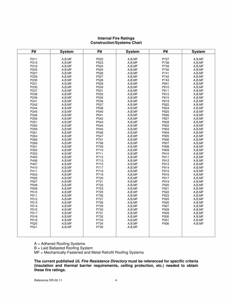
Internal Fire Ratings
Construction/Systems Chart
P# System P# System P# System
P211 P215 P216 P225 P227 P229 P230 P231 P235 P237 P238 P239 P241 P242 P244 P245 P246 P250 P251 P255 P259 P261 P264 P266 P269 P301 P302 P303 P405 P406 P407 P410 P411 P503 P505 P507 P508 P509 P510 P511 P512 P513 P514 P515 P517 P518 P519 P520 P521
A,B,MF A,B,MF A,B,MF A,B,MF A,B,MF A,B,MF A,B,MF A,B,MF A,B,MF A,B,MF A,B,MF A,B,MF A,B,MF A,B,MF A,B,MF A,B,MF A,B,MF A,B,MF A,B,MF A,B,MF A,B,MF A,B,MF A,B,MF A,B,MF A,B,MF A,B,MF A,B,MF A,B,MF A,B,MF A,B,MF A,B,MF A,B,MF A,B,MF A,B,MF A,B,MF A,B,MF A,B,MF A,B,MF A,B,MF A,B,MF A,B,MF A,B,MF A,B,MF A,B,MF A,B,MF A,B,MF A,B,MF A,B,MF A,B,MF
P522 P523 P524 P525 P526 P527 P528 P529 P530 P531 P533 P535 P536 P537 P538 P540 P541 P542 P543 P544 P545 P546 P547 P701 P708 P709 P710 P711 P712 P713 P715 P717 P718 P719 P720 P721 P722 P723 P725 P726 P727 P728 P729 P730 P731 P732 P733 P734 P735
A,B,MF A,B,MF A,B,MF A,B,MF A,B,MF A,B,MF A,B,MF A,B,MF A,B,MF A,B,MF A,B,MF A,B,MF A,B,MF A,B,MF A,B,MF A,B,MF A,B,MF A,B,MF A,B,MF A,B,MF A,B,MF A,B,MF A,B,MF A,B,MF A,B,MF A,B,MF A,B,MF A,B,MF A,B,MF A,B,MF A,B,MF A,B,MF A,B,MF A,B,MF A,B,MF A,B,MF A,B,MF A,B,MF A,B,MF A,B,MF A,B,MF A,B,MF A,B,MF A,B,MF A,B,MF A,B,MF A,B,MF A,B,MF A,B,MF
P737 P738 P739 P740 P741 P742 P743 P801 P810 P811 P812 P815 P819 P822 P824 P825 P826 P827 P828 P902 P903 P904 P905 P906 P907 P908 P909 P910 P911 P912 P913 P914 P915 P916 P917 P919 P920 P921 P922 P923 P925 P926 P927 P928 P929 P930 P931 P936
A,B,MF A,B,MF A,B,MF A,B,MF A,B,MF A,B,MF A,B,MF A,B,MF A,B,MF A,B,MF A,B,MF A,B,MF A,B,MF A,B,MF A,B,MF A,B,MF A,B,MF A,B,MF A,B,MF A,B,MF A,B,MF A,B,MF A,B,MF A,B,MF A,B,MF A,B,MF A,B,MF A,B,MF A,B,MF A,B,MF A,B,MF A,B,MF A,B,MF A,B,MF A,B,MF A,B,MF A,B,MF A,B,MF A,B,MF A,B,MF A,B,MF A,B,MF A,B,MF A,B,MF A,B,MF A,B,MF A,B,MF A,B,MF
A = Adhered Roofing Systems B = Laid Ballasted Roofing System MF = Mechanically-Fastened and Metal Retrofit Roofing Systems
The current published UL Fire Resistance Directory must be referenced for specific criteria
(insulation and thermal barrier requirements, ceiling protection, etc.) needed to obtain
these fire ratings.
Reference DR-02-11 5
FACTORY MUTUAL GLOBAL (FMG) APPROVAL TEST CRITERIA
Factory Mutual Global (FMG) approval requires that the roof construction and membrane assembly pass tests related to combustibility, wind resistance, hail resistance, water leakage, resistance to foot traffic and corrosion (FM Approval Standards 4450 and 4470). All of these tests must be successfully completed before a roofing assembly is classified as approved by FMG and then published on the FMG RoofNav system. Briefly, the test criterion consists of the following:
Combustibility
A. Above the Deck - External The test method utilized is ASTM E-108 and results in a Class A, B or C external fire rating. The description can be found under the "UL External Fire Test Criteria" in this guide. The minimum thickness for a combustible deck, which FM approves, is 3/4" tongue and groove Fire Retardant treated plywood (Refer to the current published information on FMG’s website for specific deck requirements).
B. Below the Deck - Fuel Contribution (Calorimeter) The complete roof assembly is exposed to an internal fire source for a period of 30 minutes. The heat input is carefully controlled and monitored. The test gauges the fuel contribution from the roof assembly measured at 3, 5, 10 and 30 minute intervals. At no time can this additional fuel contribution exceed certain predetermined levels.
Wind Resistance (also referred to as ANSI/FM 4474)
A test panel comprising of a roof deck, thermal barrier (optional), insulation, cover board (optional), secured to the structural deck with insulation fasteners or adhesives, and roof coverings. This assembly is exposed to air pressure from below, starting at 30 psf and held at that pressure for one minute. After each minute, the air pressure is increased an additional 15 psf and held for another full minute. This increase in pressure and time is continued until failure of the assembly. The last successful pressure before failure is the rating for the assembly. The minimum rating an assembly can receive is 60 psf. (Note the results are from a pressure test in psf, not miles per hour.)
A. Fully Adhered Roofing Systems Adhered membrane assemblies can be tested on a 5' X 9' Uplift Table for a maximum rating of 90 psf. For a higher rating that 90 psf, the assembly must be tested on the 12’ X 24’ Uplift Table.
B. Mechanically Fastened Roofing Systems All mechanically fastened roofing systems (with field membrane securement exceeding 4 feet) are required to be tested on a 12' X 24' Uplift Table.
“Enhanced Wind Uplift Resistant Roof Classifications” (greater than 90 psf ratings) Adhered and Mechanically Fastened Roofing Systems must be tested on the 12' X 24' Table resisting the noted pressures.
To determine the wind uplift rating (60 psf, 90 psf, 105 psf, etc.) appropriate for a given building, refer to the latest published FMG Property Loss Prevention Data Sheets 1-28.
Hail Resistance
Reference DR-02-11 6
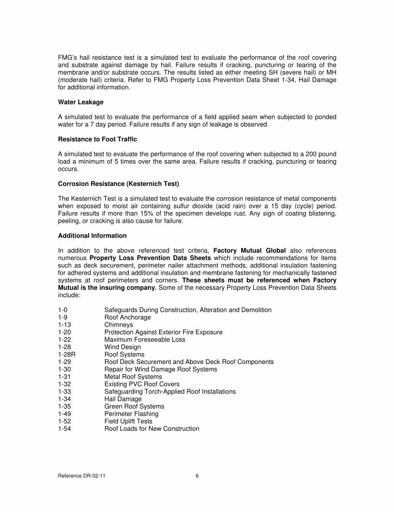
FMG’s hail resistance test is a simulated test to evaluate the performance of the roof covering and substrate against damage by hail. Failure results if cracking, puncturing or tearing of the membrane and/or substrate occurs. The results listed as either meeting SH (severe hail) or MH (moderate hail) criteria. Refer to FMG Property Loss Prevention Data Sheet 1-34, Hail Damage for additional information. Water Leakage
A simulated test to evaluate the performance of a field applied seam when subjected to ponded water for a 7 day period. Failure results if any sign of leakage is observed.
Resistance to Foot Traffic
A simulated test to evaluate the performance of the roof covering when subjected to a 200 pound load a minimum of 5 times over the same area. Failure results if cracking, puncturing or tearing occurs.
Corrosion Resistance (Kesternich Test)
The Kesternich Test is a simulated test to evaluate the corrosion resistance of metal components when exposed to moist air containing sulfur dioxide (acid rain) over a 15 day (cycle) period. Failure results if more than 15% of the specimen develops rust. Any sign of coating blistering, peeling, or cracking is also cause for failure.
Additional Information
In addition to the above referenced test criteria, Factory Mutual Global also references numerous Property Loss Prevention Data Sheets which include recommendations for items such as deck securement, perimeter nailer attachment methods, additional insulation fastening for adhered systems and additional insulation and membrane fastening for mechanically fastened systems at roof perimeters and corners. These sheets must be referenced when Factory
Mutual is the insuring company. Some of the necessary Property Loss Prevention Data Sheets include: 1-0 Safeguards During Construction, Alteration and Demolition 1-9 Roof Anchorage 1-13 Chimneys 1-20 Protection Against Exterior Fire Exposure 1-22 Maximum Foreseeable Loss 1-28 Wind Design 1-28R Roof Systems 1-29 Roof Deck Securement and Above Deck Roof Components 1-30 Repair for Wind Damage Roof Systems 1-31 Metal Roof Systems 1-32 Existing PVC Roof Covers 1-33 Safeguarding Torch-Applied Roof Installations 1-34 Hail Damage 1-35 Green Roof Systems 1-49 Perimeter Flashing 1-52 Field Uplift Tests 1-54 Roof Loads for New Construction
Reference DR-02-11 7
Determining FMG Rating Needed
Use FMG Property Loss Prevention Data Sheet 1-28 To Determine Uplift Pressure and Rating Required. FMG Data Sheet 1-28 calculations conform with the American Society of Civil Engineers (ASCE 7) with the requirement that the building importance factor = 1.15 Required Building Information
• Identify Building Height • Peak Gust Wind Zone • Openings (Open, Partially Enclosed, or Enclosed) • Determine “Ground Roughness”
- B: Urban/Suburban Areas, Well Wooded, Closely Spaced Buildings (includes large cities) - C: Open Terrain, Flat Open Country, Scattered Buildings less than 30’ High - D: Adjacent to Bodies of Water
• With the above information, use pre-calculated tables within the FMG Data Sheet 1-28 to find
“Basic Outward Pressure”. • “Basic Outward Pressure” is then multiplied by a Safety Factor of 2 resulting in the “Factored
Pressure” • Apply to the “Factored Pressure” are the appropriate pressure multipliers for the roof slope,
zone, and enclosed or partially enclosed buildings, to determine the “Design Pressures” for the field, perimeter, and corners.
• Note: ASCE 7 does not identify a safety factor.
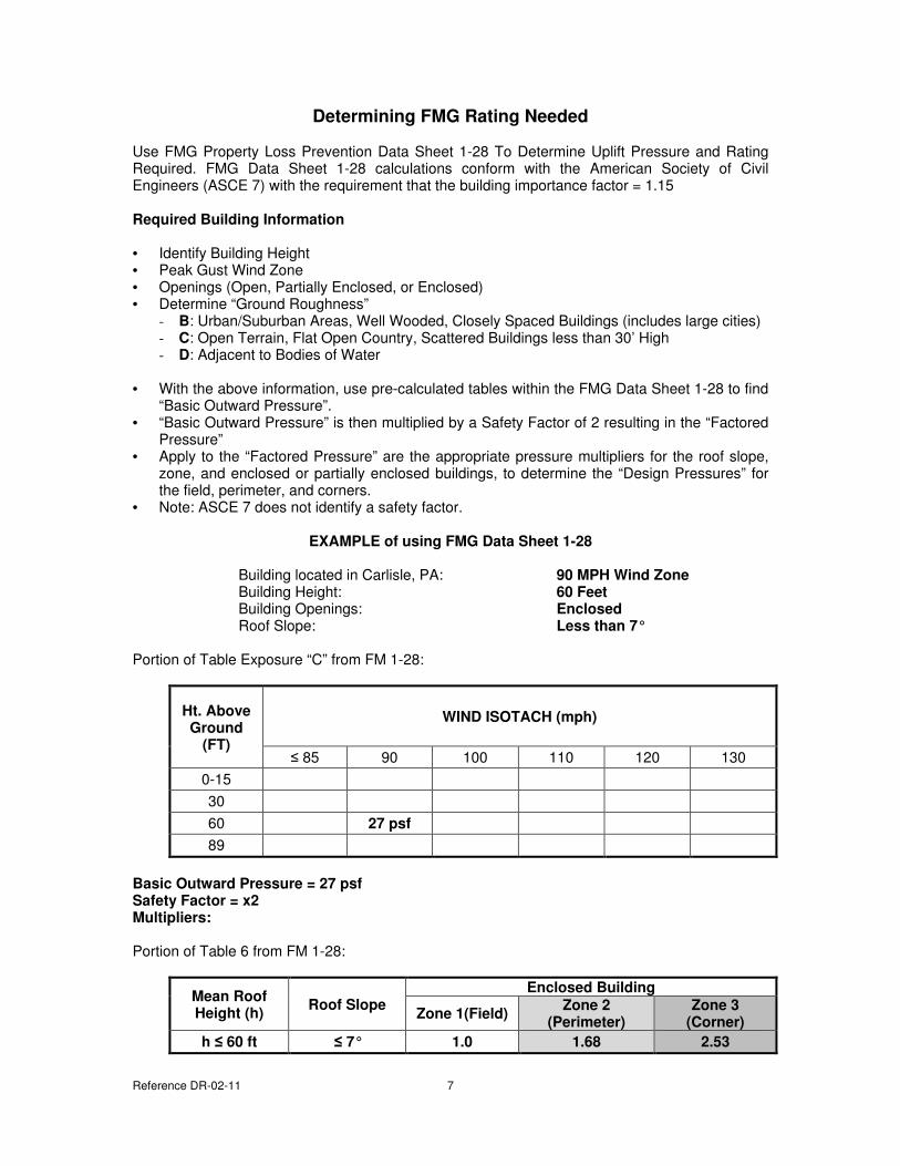
EXAMPLE of using FMG Data Sheet 1-28
Building located in Carlisle, PA: 90 MPH Wind Zone
Building Height: 60 Feet
Building Openings: Enclosed Roof Slope: Less than 7°
Portion of Table Exposure “C” from FM 1-28:
Ht. Above
Ground
(FT)
WIND ISOTACH (mph)
≤ 85 90 100 110 120 130
0-15
30
60 27 psf
89
Basic Outward Pressure = 27 psf
Safety Factor = x2
Multipliers:
Portion of Table 6 from FM 1-28:
Mean Roof
Height (h) Roof Slope
Enclosed Building
Zone 1(Field) Zone 2
(Perimeter)
Zone 3
(Corner)
h ≤ 60 ft ≤ 7° 1.0 1.68 2.53
Reference DR-02-11 8
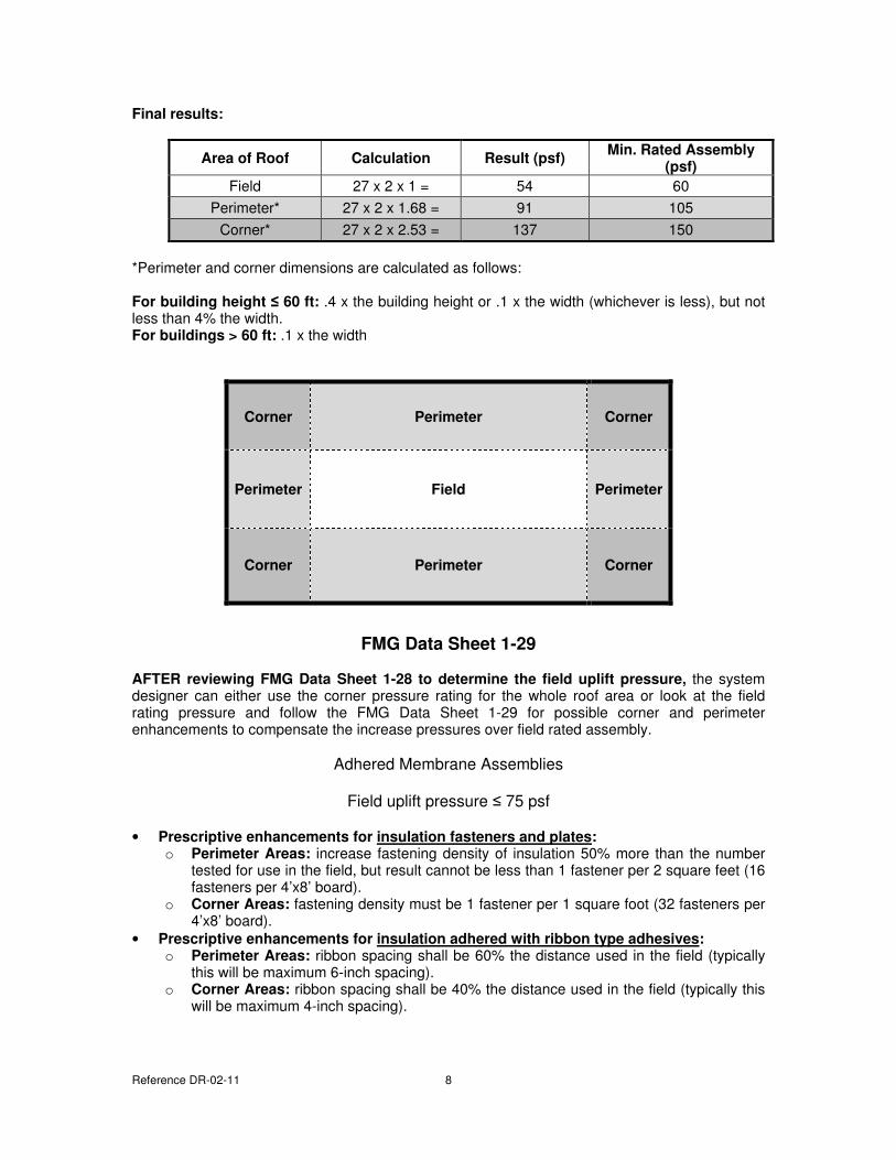
Final results:
Area of Roof Calculation Result (psf) Min. Rated Assembly
(psf)
Field 27 x 2 x 1 = 54 60
Perimeter* 27 x 2 x 1.68 = 91 105
Corner* 27 x 2 x 2.53 = 137 150
*Perimeter and corner dimensions are calculated as follows:
For building height ≤ 60 ft: .4 x the building height or .1 x the width (whichever is less), but not less than 4% the width. For buildings > 60 ft: .1 x the width
FMG Data Sheet 1-29
AFTER reviewing FMG Data Sheet 1-28 to determine the field uplift pressure, the system designer can either use the corner pressure rating for the whole roof area or look at the field rating pressure and follow the FMG Data Sheet 1-29 for possible corner and perimeter enhancements to compensate the increase pressures over field rated assembly.
Adhered Membrane Assemblies
Field uplift pressure ≤ 75 psf
• Prescriptive enhancements for insulation fasteners and plates:
o Perimeter Areas: increase fastening density of insulation 50% more than the number tested for use in the field, but result cannot be less than 1 fastener per 2 square feet (16 fasteners per 4’x8’ board).
o Corner Areas: fastening density must be 1 fastener per 1 square foot (32 fasteners per 4’x8’ board).
• Prescriptive enhancements for insulation adhered with ribbon type adhesives:
o Perimeter Areas: ribbon spacing shall be 60% the distance used in the field (typically this will be maximum 6-inch spacing).
o Corner Areas: ribbon spacing shall be 40% the distance used in the field (typically this will be maximum 4-inch spacing).
Corner Perimeter Corner
Perimeter Field Perimeter
Corner Perimeter Corner
Reference DR-02-11 9
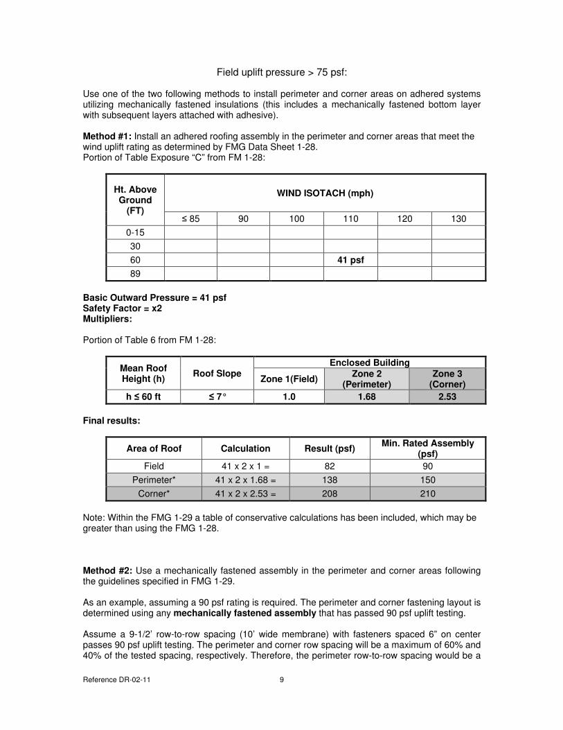
Field uplift pressure > 75 psf: Use one of the two following methods to install perimeter and corner areas on adhered systems utilizing mechanically fastened insulations (this includes a mechanically fastened bottom layer with subsequent layers attached with adhesive).
Method #1: Install an adhered roofing assembly in the perimeter and corner areas that meet the wind uplift rating as determined by FMG Data Sheet 1-28. Portion of Table Exposure “C” from FM 1-28:
Ht. Above
Ground
(FT)
WIND ISOTACH (mph)
≤ 85 90 100 110 120 130
0-15
30
60 41 psf
89
Basic Outward Pressure = 41 psf
Safety Factor = x2
Multipliers:
Portion of Table 6 from FM 1-28:
Mean Roof
Height (h) Roof Slope
Enclosed Building
Zone 1(Field) Zone 2
(Perimeter)
Zone 3
(Corner)
h ≤ 60 ft ≤ 7° 1.0 1.68 2.53
Final results:
Area of Roof Calculation Result (psf) Min. Rated Assembly
(psf)
Field 41 x 2 x 1 = 82 90
Perimeter* 41 x 2 x 1.68 = 138 150
Corner* 41 x 2 x 2.53 = 208 210
Note: Within the FMG 1-29 a table of conservative calculations has been included, which may be greater than using the FMG 1-28.
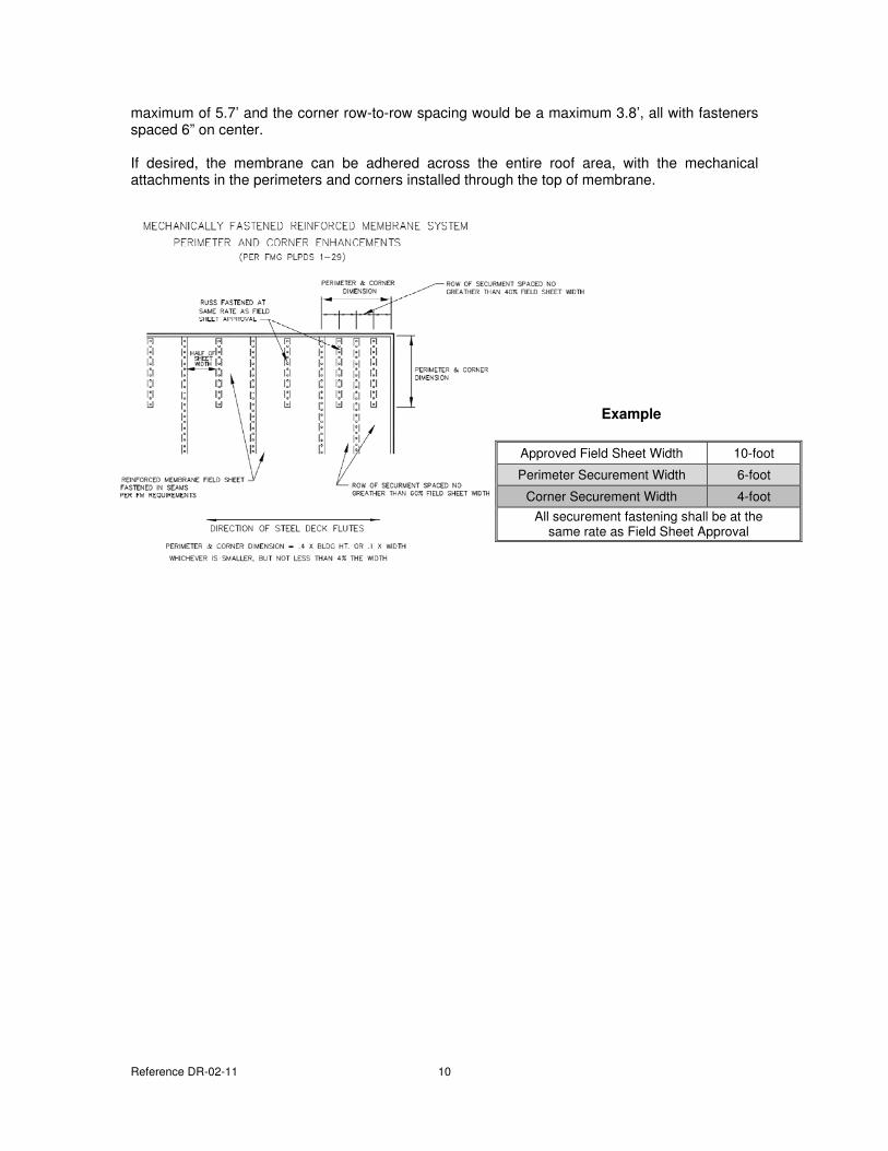
Method #2: Use a mechanically fastened assembly in the perimeter and corner areas following the guidelines specified in FMG 1-29. As an example, assuming a 90 psf rating is required. The perimeter and corner fastening layout is determined using any mechanically fastened assembly that has passed 90 psf uplift testing. Assume a 9-1/2’ row-to-row spacing (10’ wide membrane) with fasteners spaced 6” on center passes 90 psf uplift testing. The perimeter and corner row spacing will be a maximum of 60% and 40% of the tested spacing, respectively. Therefore, the perimeter row-to-row spacing would be a
Reference DR-02-11 10
maximum of 5.7’ and the corner row-to-row spacing would be a maximum 3.8’, all with fasteners spaced 6” on center. If desired, the membrane can be adhered across the entire roof area, with the mechanical attachments in the perimeters and corners installed through the top of membrane.
Example
Approved Field Sheet Width 10-foot
Perimeter Securement Width 6-foot
Corner Securement Width 4-foot
All securement fastening shall be at the same rate as Field Sheet Approval
Reference DR-02-11 11
ASCE 7 Compliance
ANSI/SPRI WD-1: Wind Design Standard Practice for Roofing Assemblies
FM Global (FMG) is an insurance standard and is required to be followed if the building is FMG insured, however it is not a building code standard. The International Building Code requires that each roofing assembly must be certified to meet or exceed the calculated pressures following the ASCE 7.
The ANSI/SPRI WD-1provides a two-part methodology for determining the wind uplift pressures at roof deck for non-ballasted single-ply roofing system assemblies. (Refer to the ANSI/SPRI RP-4 Standard for wind design requirements of ballasted single-ply roofing systems).
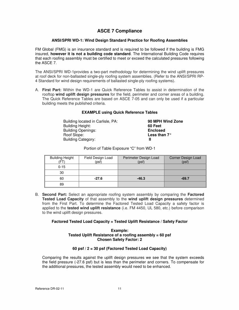
A. First Part: Within the WD-1 are Quick Reference Tables to assist in determination of the rooftop wind uplift design pressures for the field, perimeter and corner areas of a building. The Quick Reference Tables are based on ASCE 7-05 and can only be used if a particular building meets the published criteria.
EXAMPLE using Quick Reference Tables
Building located in Carlisle, PA: 90 MPH Wind Zone
Building Height: 60 Feet
Building Openings: Enclosed
Roof Slope: Less than 7°
Building Category: II
Portion of Table Exposure “C” from WD-1
Building Height (FT)
Field Design Load (psf)
Perimeter Design Load (psf)
Corner Design Load (psf)
0-15
30
60 -27.6 -46.3 -69.7
89
B. Second Part: Select an appropriate roofing system assembly by comparing the Factored
Tested Load Capacity of that assembly to the wind uplift design pressures determined from the First Part. To determine the Factored Tested Load Capacity a safety factor is applied to the tested wind uplift resistance (i.e. FM 4450, UL 580, etc.) before comparison to the wind uplift design pressures.
Factored Tested Load Capacity = Tested Uplift Resistance / Safety Factor
Example:
Tested Uplift Resistance of a roofing assembly = 60 psf
Chosen Safety Factor: 2
60 psf / 2 = 30 psf (Factored Tested Load Capacity)
Comparing the results against the uplift design pressures we see that the system exceeds the field pressure (-27.6 psf) but is less than the perimeter and corners. To compensate for the additional pressures, the tested assembly would need to be enhanced.
Reference DR-02-11 12
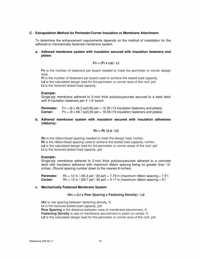
C. Extrapolation Method for Perimeter/Corner Insulation or Membrane Attachment
To determine the enhancement requirements depends on the method of installation for the adhered or mechanically fastened membrane system.
a. Adhered membrane system with insulation secured with insulation fasteners and
plates:
Fn = (Ft x Ld) / Lt
Fn is the number of fasteners per board needed to meet the perimeter or corner design load. Ft is the number of fasteners per board used to achieve the tested load capacity. Ld is the calculated design load for the perimeter or corner area of the roof, psf. Lt is the factored tested load capacity.
Example:
Single-ply membrane adhered to 2-inch thick polyisocyanurate secured to a steel deck with 8 insulation fasteners per 4’ x 8’ board. Perimeter: Fn = (8 x 46.3 psf)/30 psf = 12.35 (13 insulation fasteners and plates) Corner: Fn = (8 x 69.7 psf)/30 psf = 18.59 (19 insulation fasteners and plates)
b. Adhered membrane system with insulation secured with insulation adhesives
(ribbons):
Rn = Rt /(Ld / Lt)
Rn is the ribbon/bead spacing needed to meet the design load, inches. Rt is the ribbon/bead spacing used to achieve the tested load capacity, inches. Ld is the calculated design load for the perimeter or corner areas of the roof, psf. Lt is the factored tested load capacity, psf.
Example:
Single-ply membrane adhered to 2-inch thick polyisocyanurate adhered to a concrete deck with insulation adhesive with maximum ribbon spacing being no greater than 12-inches. (Round spacing number down to the nearest 6 inches) Perimeter: Rn = 12 in / (46.3 psf / 30 psf) = 7.79 in (maximum ribbon spacing = 7.5”) Corner: Rn = 12 in / (69.7 psf / 30 psf) = 5.17 in (maximum ribbon spacing = 5”)
c. Mechanically Fastened Membrane System
IAn = (Lt x Row Spacing x Fastening Density) / Ld
IAn is row spacing between fastening density, ft. Lt is the factored tested load capacity, psf. Row Spacing is the distance between rows of membrane securement, ft. Fastening Density is rate of membrane securement in seam on center, ft. Ld is the calculated design load for the perimeter or corner area of the roof, psf.
Reference DR-02-11 13
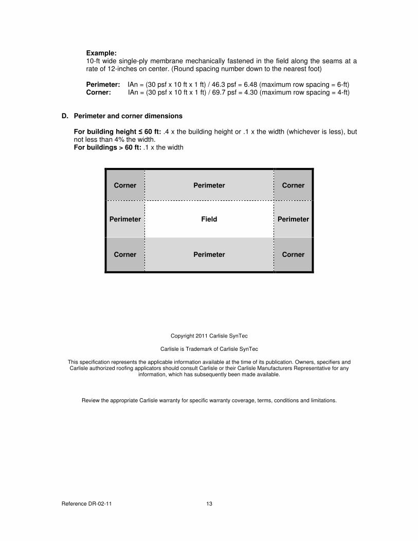
Example:
10-ft wide single-ply membrane mechanically fastened in the field along the seams at a rate of 12-inches on center. (Round spacing number down to the nearest foot) Perimeter: IAn = (30 psf x 10 ft x 1 ft) / 46.3 psf = 6.48 (maximum row spacing = 6-ft) Corner: IAn = (30 psf x 10 ft x 1 ft) / 69.7 psf = 4.30 (maximum row spacing = 4-ft)
D. Perimeter and corner dimensions
For building height ≤ 60 ft: .4 x the building height or .1 x the width (whichever is less), but not less than 4% the width. For buildings > 60 ft: .1 x the width
Copyright 2011 Carlisle SynTec
Carlisle is Trademark of Carlisle SynTec
This specification represents the applicable information available at the time of its publication. Owners, specifiers and Carlisle authorized roofing applicators should consult Carlisle or their Carlisle Manufacturers Representative for any
information, which has subsequently been made available.
Review the appropriate Carlisle warranty for specific warranty coverage, terms, conditions and limitations.
Corner Perimeter Corner
Perimeter Field Perimeter
Corner Perimeter Corner
DR-05-11
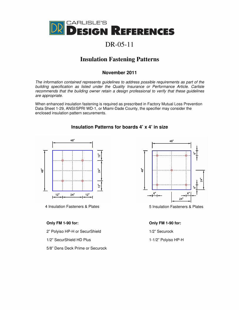
Insulation Fastening Patterns
November 2011
The information contained represents guidelines to address possible requirements as part of the building specification as listed under the Quality Insurance or Performance Article. Carlisle recommends that the building owner retain a design professional to verify that these guidelines are appropriate.
When enhanced insulation fastening is required as prescribed in Factory Mutual Loss Prevention Data Sheet 1-29, ANSI/SPRI WD-1, or Miami-Dade County, the specifier may consider the enclosed insulation pattern securements.
Insulation Patterns for boards 4’ x 4’ in size
4 Insulation Fasteners & Plates 5 Insulation Fasteners & Plates
Only FM 1-90 for:
2” Polyiso HP-H or SecurShield
1/2” SecurShield HD Plus
5/8” Dens Deck Prime or Securock
Only FM 1-90 for:
1/2” Securock
1-1/2” Polyiso HP-H
References DR-05-11 2
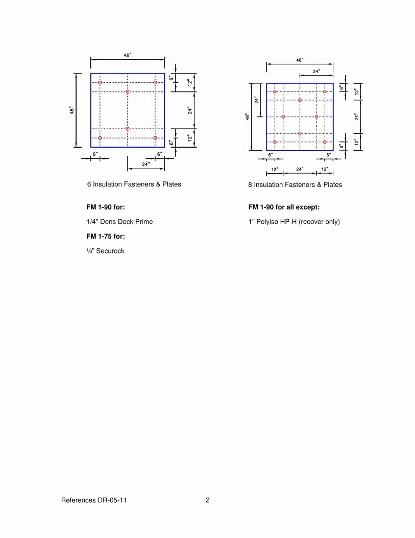
8 Insulation Fasteners & Plates 6 Insulation Fasteners & Plates
FM 1-90 for:
1/4" Dens Deck Prime
FM 1-75 for:
¼” Securock
FM 1-90 for all except:
1” Polyiso HP-H (recover only)
References DR-05-11 3
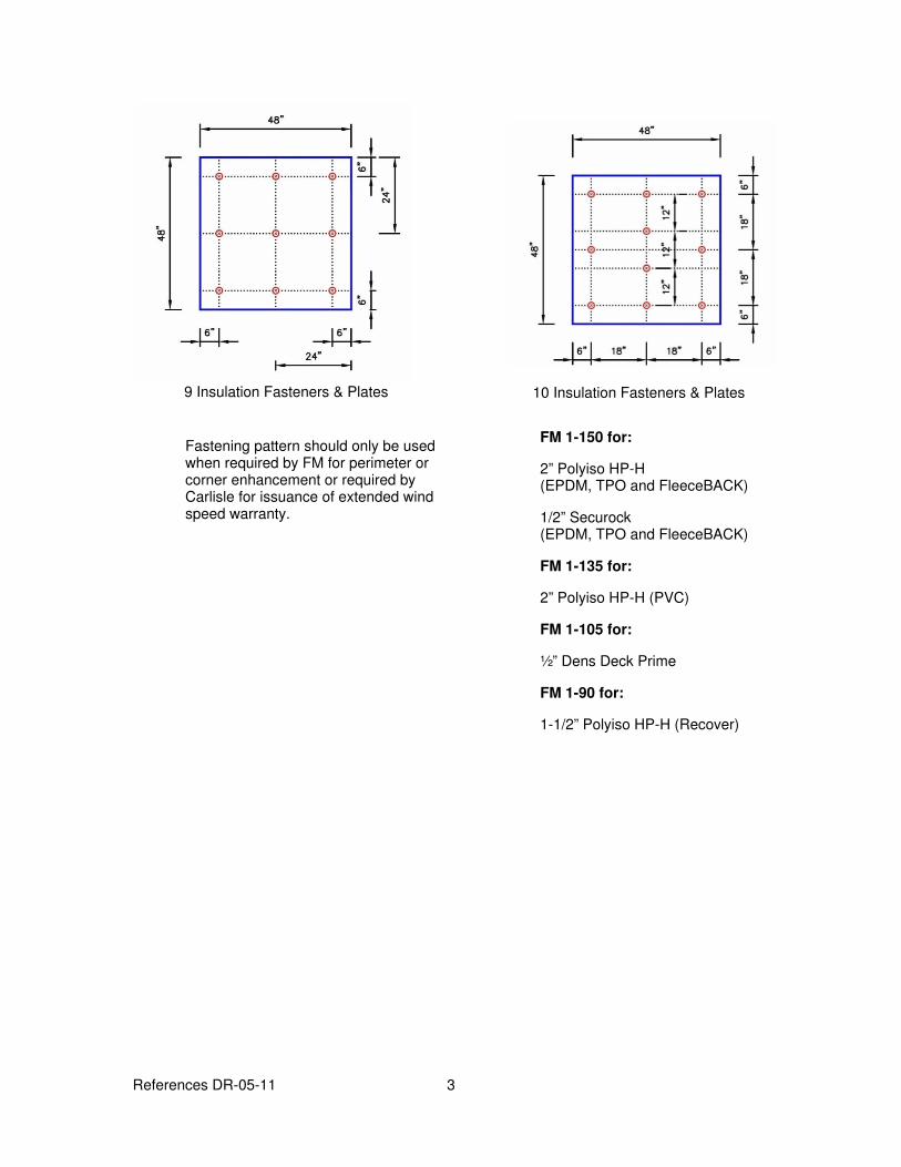
10 Insulation Fasteners & Plates 9 Insulation Fasteners & Plates
Fastening pattern should only be used when required by FM for perimeter or corner enhancement or required by Carlisle for issuance of extended wind speed warranty.
FM 1-150 for:
2” Polyiso HP-H (EPDM, TPO and FleeceBACK)
1/2” Securock (EPDM, TPO and FleeceBACK)
FM 1-135 for:
2” Polyiso HP-H (PVC)
FM 1-105 for:
½” Dens Deck Prime
FM 1-90 for:
1-1/2” Polyiso HP-H (Recover)
References DR-05-11 4
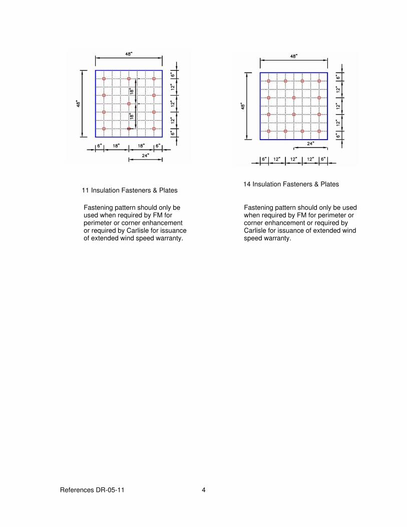
11 Insulation Fasteners & Plates 14 Insulation Fasteners & Plates
Fastening pattern should only be used when required by FM for perimeter or corner enhancement or required by Carlisle for issuance of extended wind speed warranty.
Fastening pattern should only be used when required by FM for perimeter or corner enhancement or required by Carlisle for issuance of extended wind speed warranty.
References DR-05-11 5
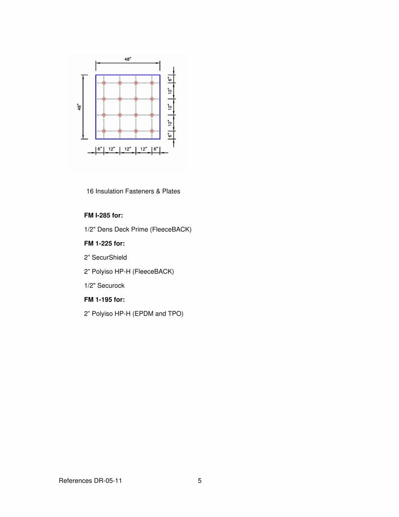
16 Insulation Fasteners & Plates
FM I-285 for:
1/2" Dens Deck Prime (FleeceBACK)
FM 1-225 for:
2” SecurShield
2” Polyiso HP-H (FleeceBACK)
1/2" Securock
FM 1-195 for:
2” Polyiso HP-H (EPDM and TPO)
References DR-05-11 6
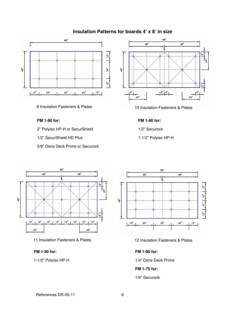
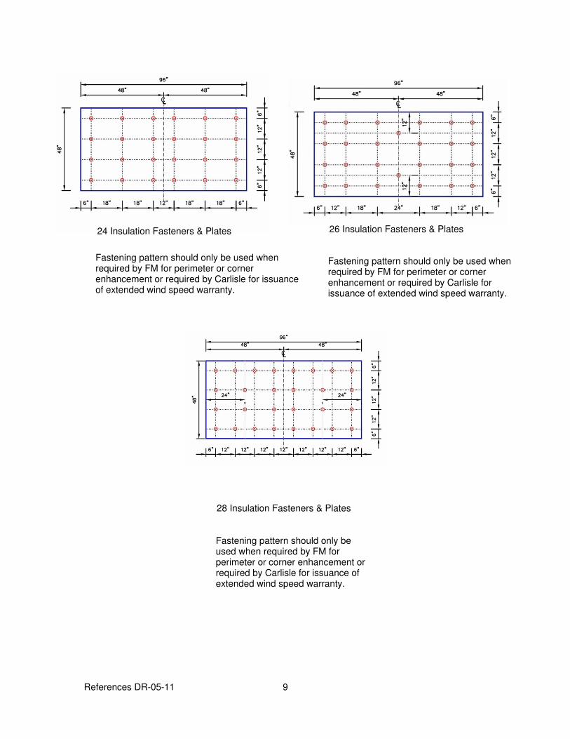
Insulation Patterns for boards 4’ x 8’ in size
8 Insulation Fasteners & Plates 10 Insulation Fasteners & Plates
11 Insulation Fasteners & Plates 12 Insulation Fasteners & Plates
FM 1-90 for:
2” Polyiso HP-H or SecurShield
1/2” SecurShield HD Plus
5/8” Dens Deck Prime or Securock
FM 1-90 for:
1/2" Securock
1-1/2” Polyiso HP-H
FM 1-90 for:
1-1/2” Polyiso HP-H
FM 1-90 for:
1/4” Dens Deck Prime
FM 1-75 for:
1/4” Securock
References DR-05-11 7
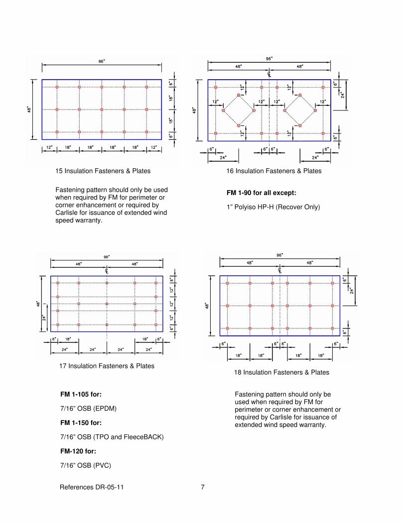
16 Insulation Fasteners & Plates 15 Insulation Fasteners & Plates
17 Insulation Fasteners & Plates 18 Insulation Fasteners & Plates
Fastening pattern should only be used when required by FM for perimeter or corner enhancement or required by Carlisle for issuance of extended wind speed warranty.
FM 1-90 for all except:
1” Polyiso HP-H (Recover Only)
Fastening pattern should only be used when required by FM for perimeter or corner enhancement or required by Carlisle for issuance of extended wind speed warranty.
FM 1-105 for:
7/16” OSB (EPDM)
FM 1-150 for:
7/16” OSB (TPO and FleeceBACK)
FM-120 for:
7/16” OSB (PVC)
References DR-05-11 8
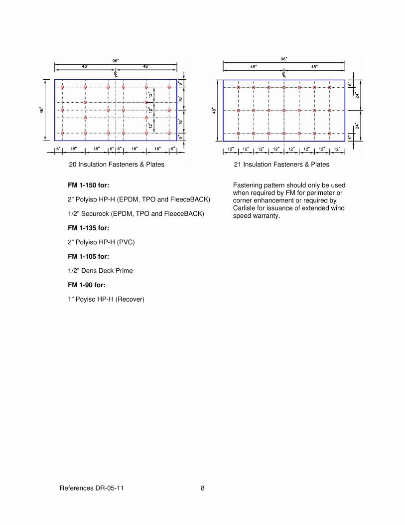
20 Insulation Fasteners & Plates 21 Insulation Fasteners & Plates
FM 1-150 for:
2” Polyiso HP-H (EPDM, TPO and FleeceBACK)
1/2" Securock (EPDM, TPO and FleeceBACK)
FM 1-135 for:
2” Polyiso HP-H (PVC)
FM 1-105 for:
1/2" Dens Deck Prime
FM 1-90 for:
1” Poyiso HP-H (Recover)
Fastening pattern should only be used when required by FM for perimeter or corner enhancement or required by Carlisle for issuance of extended wind speed warranty.
References DR-05-11 9
24 Insulation Fasteners & Plates 26 Insulation Fasteners & Plates
28 Insulation Fasteners & Plates
Fastening pattern should only be used when required by FM for perimeter or corner enhancement or required by Carlisle for issuance of extended wind speed warranty.
Fastening pattern should only be used when required by FM for perimeter or corner enhancement or required by Carlisle for issuance of extended wind speed warranty.
Fastening pattern should only be used when required by FM for perimeter or corner enhancement or required by Carlisle for issuance of extended wind speed warranty.
References DR-05-11 10
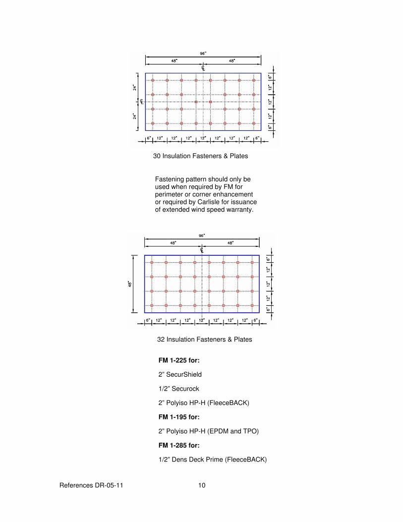
30 Insulation Fasteners & Plates
32 Insulation Fasteners & Plates
Fastening pattern should only be used when required by FM for perimeter or corner enhancement or required by Carlisle for issuance of extended wind speed warranty.
FM 1-225 for:
2” SecurShield
1/2” Securock
2” Polyiso HP-H (FleeceBACK)
FM 1-195 for:
2” Polyiso HP-H (EPDM and TPO)
FM 1-285 for:
1/2” Dens Deck Prime (FleeceBACK)
References DR-05-11 11
Copyright 2011 Carlisle SynTec
Carlisle, FIeeceBACK, and SecurShield are Trademarks of Carlisle SynTec
Securock is a Trademark of USG Corporation
Dens Deck and Dens Deck Prime is a Trademark of Georgia-Pacific Gypsum LLC
This specification represents the applicable information available at the time of its publication. Owners, specifiers and Carlisle authorized roofing applicators should consult Carlisle or their Carlisle Manufacturers Representative for any
information, which has subsequently been made available.
Review the appropriate Carlisle warranty for specific warranty coverage, terms, conditions and limitations.
DR-06-11
Withdrawal Resistance Criteria
November 2011
The information contained represents guidelines to address possible requirements as part of the building specification as listed under the Quality Assurance or Performance Article. Carlisle recommends that the building owner retain a design professional to verify that these guidelines are appropriate.
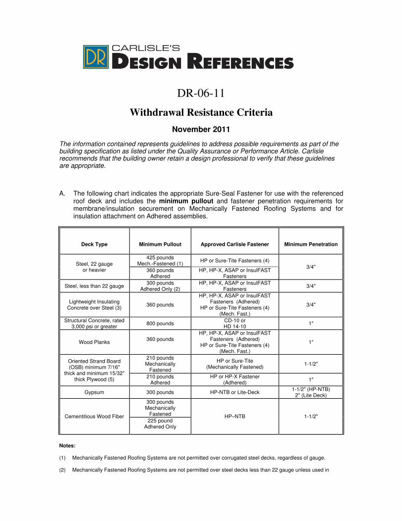
A. The following chart indicates the appropriate Sure-Seal Fastener for use with the referenced roof deck and includes the minimum pullout and fastener penetration requirements for membrane/insulation securement on Mechanically Fastened Roofing Systems and for insulation attachment on Adhered assemblies.
Deck Type
Minimum Pullout
Approved Carlisle Fastener
Minimum Penetration
Steel, 22 gauge or heavier
425 pounds Mech.-Fastened (1)
HP or Sure-Tite Fasteners (4)
3/4" 360 pounds
Adhered HP, HP-X, ASAP or InsulFAST
Fasteners
Steel, less than 22 gauge 300 pounds
Adhered Only (2) HP, HP-X, ASAP or InsulFAST
Fasteners 3/4"
Lightweight Insulating Concrete over Steel (3)
360 pounds
HP, HP-X, ASAP or InsulFAST Fasteners (Adhered)
HP or Sure-Tite Fasteners (4) (Mech. Fast.)
3/4"
Structural Concrete, rated 3,000 psi or greater
800 pounds CD-10 or HD 14-10
1"
Wood Planks 360 pounds
HP, HP-X, ASAP or InsulFAST Fasteners (Adhered)
HP or Sure-Tite Fasteners (4) (Mech. Fast.)
1"
Oriented Strand Board (OSB) minimum 7/16"
thick and minimum 15/32" thick Plywood (5)
210 pounds Mechanically
Fastened
HP or Sure-Tite (Mechanically Fastened)
1-1/2"
210 pounds Adhered
HP or HP-X Fastener (Adhered)
1"
Gypsum 300 pounds HP-NTB or Lite-Deck 1-1/2" (HP-NTB)
2" (Lite Deck)
Cementitious Wood Fiber
300 pounds Mechanically
Fastened HP–NTB 1-1/2" 225 pound
Adhered Only
Notes:
(1) Mechanically Fastened Roofing Systems are not permitted over corrugated steel decks, regardless of gauge. (2) Mechanically Fastened Roofing Systems are not permitted over steel decks less than 22 gauge unless used in
Reference DR-06-11 2
conjunction with lightweight insulating concrete and acceptable pullouts are obtained using HP or Sure-Tite Fasteners.
(3) Fasteners are installed through the lightweight insulating concrete into the steel deck below. (4) Sure-Tite Fasteners can be used on Mechanically Fastened Roofing Systems in conjunction with ST Metal
Fastening Bars. (5) 7/16” OSB or 5/8” OSB and 15/32” 3-Ply Plywood 3-Ply or 15/32” 5-Ply Plywood.
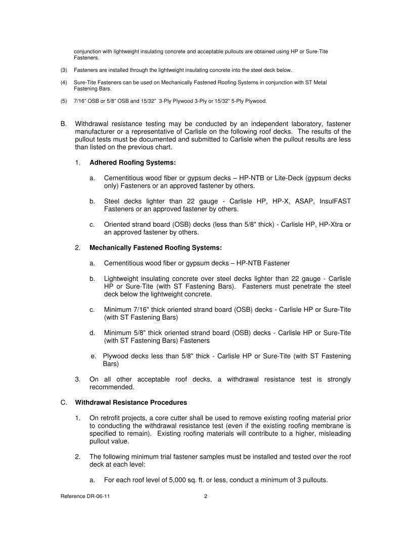
B. Withdrawal resistance testing may be conducted by an independent laboratory, fastener manufacturer or a representative of Carlisle on the following roof decks. The results of the pullout tests must be documented and submitted to Carlisle when the pullout results are less than listed on the previous chart.
1. Adhered Roofing Systems:
a. Cementitious wood fiber or gypsum decks – HP-NTB or Lite-Deck (gypsum decks
only) Fasteners or an approved fastener by others.
b. Steel decks lighter than 22 gauge - Carlisle HP, HP-X, ASAP, InsulFAST Fasteners or an approved fastener by others.
c. Oriented strand board (OSB) decks (less than 5/8" thick) - Carlisle HP, HP-Xtra or
an approved fastener by others.
2. Mechanically Fastened Roofing Systems:
a. Cementitious wood fiber or gypsum decks – HP-NTB Fastener
b. Lightweight insulating concrete over steel decks lighter than 22 gauge - Carlisle
HP or Sure-Tite (with ST Fastening Bars). Fasteners must penetrate the steel deck below the lightweight concrete.
c. Minimum 7/16" thick oriented strand board (OSB) decks - Carlisle HP or Sure-Tite
(with ST Fastening Bars)
d. Minimum 5/8" thick oriented strand board (OSB) decks - Carlisle HP or Sure-Tite (with ST Fastening Bars) Fasteners
e. Plywood decks less than 5/8" thick - Carlisle HP or Sure-Tite (with ST Fastening
Bars)
3. On all other acceptable roof decks, a withdrawal resistance test is strongly recommended.
C. Withdrawal Resistance Procedures
1. On retrofit projects, a core cutter shall be used to remove existing roofing material prior
to conducting the withdrawal resistance test (even if the existing roofing membrane is specified to remain). Existing roofing materials will contribute to a higher, misleading pullout value.
2. The following minimum trial fastener samples must be installed and tested over the roof
deck at each level:
a. For each roof level of 5,000 sq. ft. or less, conduct a minimum of 3 pullouts.
Reference DR-06-11 3
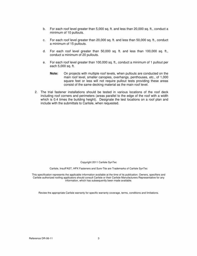
b. For each roof level greater than 5,000 sq. ft. and less than 20,000 sq. ft., conduct a
minimum of 10 pullouts.
c. For each roof level greater than 20,000 sq. ft. and less than 50,000 sq. ft., conduct a minimum of 15 pullouts.
d. For each roof level greater than 50,000 sq. ft. and less than 100,000 sq. ft.,
conduct a minimum of 20 pullouts.
e. For each roof level greater than 100,000 sq. ft., conduct a minimum of 1 pullout per each 5,000 sq. ft.
Note: On projects with multiple roof levels, when pullouts are conducted on the
main roof level, smaller canopies, overhangs, penthouses, etc., of 1,000 square feet or less will not require pullout tests providing these areas consist of the same decking material as the main roof level.
2. The trial fastener installations should be tested in various locations of the roof deck
including roof corners and perimeters (areas parallel to the edge of the roof with a width which is 0.4 times the building height). Designate the test locations on a roof plan and include with the submittals to Carlisle, when requested.
Copyright 2011 Carlisle SynTec
Carlisle, InsulFAST, HPX Fasteners and Sure-Tite are Trademarks of Carlisle SynTec
This specification represents the applicable information available at the time of its publication. Owners, specifiers and Carlisle authorized roofing applicators should consult Carlisle or their Carlisle Manufacturers Representative for any
information, which has subsequently been made available.
Review the appropriate Carlisle warranty for specific warranty coverage, terms, conditions and limitations.
DR-07-11
CRRC / LEED Information
November 2011
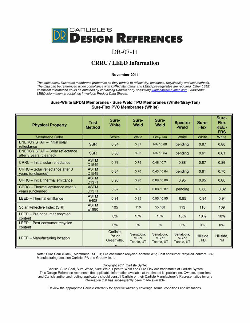
The table below illustrates membrane properties as they pertain to reflectivity, emittance, recyclability and test methods. The data can be referenced when compliance with CRRC standards and LEED pre-requisites are required. Other LEED compliant information could be obtained by contacting Carlisle or by consulting www.carlisle-syntec.com . Additional LEED information is contained in various Product Data Sheets.
Sure-White EPDM Membranes - Sure Weld TPO Membranes (White/Gray/Tan)
Sure-Flex PVC Membranes (White)
Physical Property Test
Method
Sure-
White
Sure-
Weld
Sure-
Weld
Spectro
-Weld
Sure-
Flex
Sure-
Flex
KEE /
FRS
Membrane Color White White Gray/Tan White White White
ENERGY STAR – Initial solar reflectance
SSR 0.84 0.87 NA / 0.68 pending 0.87 0.86
ENERGY STAR – Solar reflectance after 3 years (cleaned)
SSR 0.80 0.83 NA / 0.64 pending 0.61 0.61
CRRC – Initial solar reflectance ASTM C1549
0.76 0.79 0.46 / 0.71 0.88 0.87 0.86
CRRC – Solar reflectance after 3 years (uncleaned)
ASTM C1549
0.64 0.70 0.43 / 0.64 pending 0.61 0.70
CRRC – Initial thermal emittance ASTM C1371
0.90 0.90 0.89 / 0.86 0.95 0.95 0.86
CRRC – Thermal emittance after 3 years (uncleaned)
ASTM C1371
0.87 0.86 0.88 / 0.87 pending 0.86 0.82
LEED – Thermal emittance ASTM E408
0.91 0.95 0.95 / 0.95 0.95 0.94 0.94
Solar Reflective Index (SRI) ASTM E1980
105 110 55 / 88 113 110 109
LEED – Pre-consumer recycled content
0% 10% 10% 10% 10% 10%
LEED – Post-consumer recycled content
0% 0% 0% 0% 0% 0%
LEED – Manufacturing location
Carlisle, PA or
Greenville, IL
Senatobia, MS or
Tooele, UT
Senatobia, MS or
Tooele, UT
Senatobia, MS or
Tooele, UT
Hillside, NJ
Hillside, NJ
Note: Sure-Seal (Black) Membrane: SRI 9; Pre-consumer recycled content o%; Post-consumer recycled content 3%; Manufacturing Location Carlisle, PA and Greenville, IL.
Copyright 2011 Carlisle Syntec Carlisle, Sure-Seal, Sure-White, Sure-Weld, Spectro-Weld and Sure-Flex are trademarks of Carlisle Syntec
This Design Reference represents the applicable information available at the time of its publication. Owners, specifiers and Carlisle authorized roofing applicators should consult Carlisle or their Carlisle Manufacturer’s Representative for any
information that has subsequently been made available.
Review the appropriate Carlisle Warranty for specific warranty coverage, terms, conditions and limitations.
DR-08-11
Wood Nailers and Securement Criteria (Factory Mutual Loss Prevention Data Sheet 1-49)
November 2011
The information contained represents guidelines to address possible requirements as part of the building specification as listed under the Quality Assurance or Performance Article. Carlisle recommends that the building owner retain a design professional to verify that these guidelines are appropriate.
One of the most often overlooked details on a roofing system is the attachment method for wood nailers at the perimeter of the roof. Factory Mutual Global (FMG) publishes design recommendations for the attachment of wood nailers to various substrates and for the attachment of perimeter flashing details to wood nailers. This information is contained in Factory Mutual's Property Loss Prevention Data Sheet 1-49. In accordance with that Data Sheet, the information listed below should be referenced when selecting an appropriate perimeter attachment method.
General Criteria
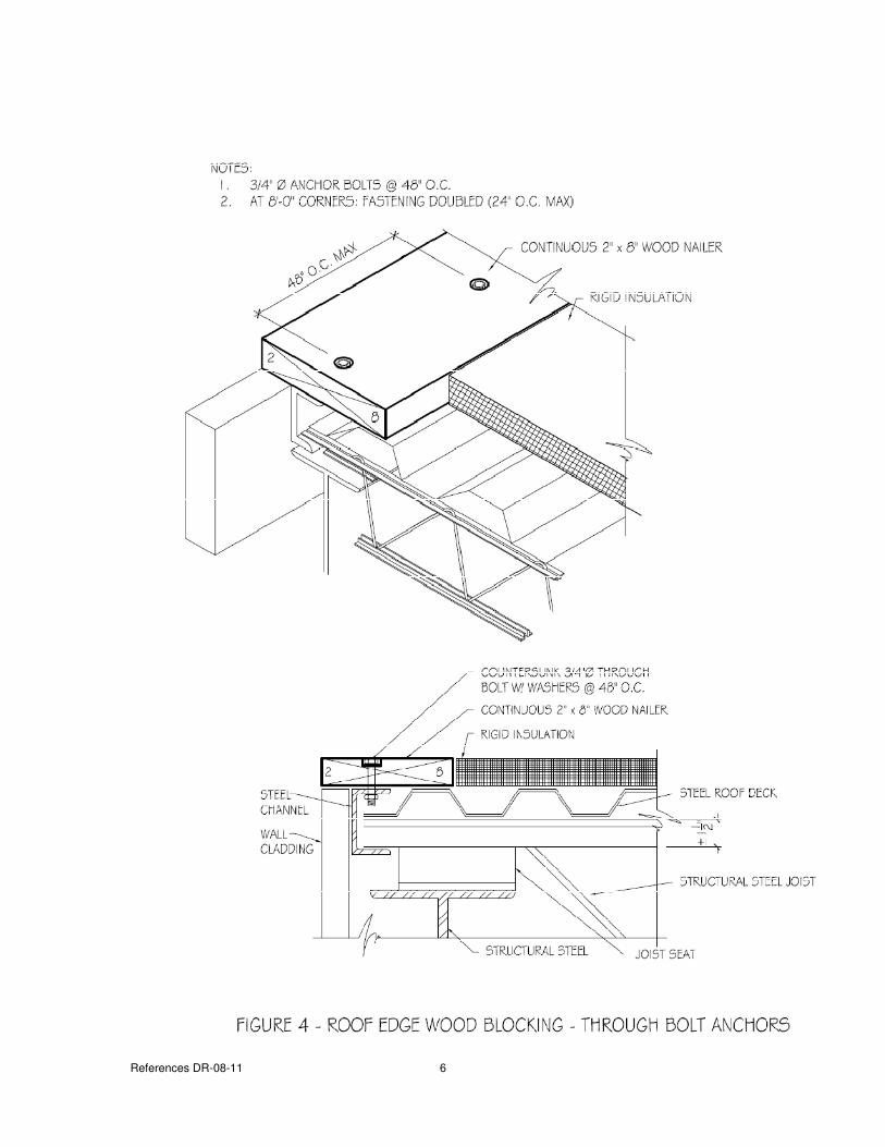
A horizontal wood nailer is used to provide an effective substrate for some installation details and for other roof accessories. In addition, it is used to provide solid protection for the edge of the membrane underlayment. Minimum thickness of the nailer must be thick enough that the top of the nailer is flush with the top of the membrane underlayment.
1. The width of the nailers must exceed the width of the metal flange of edgings, scuppers,
etc. 2. When treated lumber is specified, it is recommended that only lumber that has been
pressure treated with salt preservatives be specified. Lumber treated with any of the wood preservatives such as, Creosote, Pentachlorophenol, Copper Naphthenate and Copper 8-quinolinolate will adversely affect the membrane when in direct contact and are, therefore, unacceptable.
If non-treated lumber is to be specified, it must be stored to protect from moisture sources. A seal should be provided between the non-treated lumber and a concrete or gypsum substrate (similar to a sill sealer).
3. Methods used to fasten the nailer vary with building conditions; however, it is essential
that secure attachment of durable stock be accomplished. Factory Mutual Loss Prevention Data Bulletin 1-49 (Perimeter Flashing) contains options for the spacing and sizing of fasteners based on the project wind zone.
4. Wood nailers are not covered by the Carlisle warranty.
References DR-08-11 2
• Wood nailers that are anchored to steel, wood or masonry decking should not be less than 2"
X 6" nominal (minimum1-1/2" X 5-1/2"). • Wood nailers should be Douglas Fir, Southern Yellow Pine or of wood having similar decay
resistant properties.
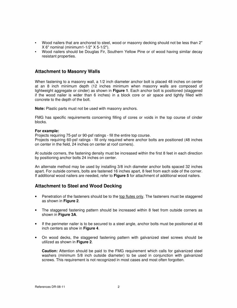
Attachment to Masonry Walls
When fastening to a masonry wall, a 1/2 inch diameter anchor bolt is placed 48 inches on center at an 8 inch minimum depth (12 inches minimum when masonry walls are composed of lightweight aggregate or cinder) as shown in Figure 1. Each anchor bolt is positioned (staggered if the wood nailer is wider than 6 inches) in a block core or air space and tightly filled with concrete to the depth of the bolt.
Note: Plastic parts must not be used with masonry anchors. FMG has specific requirements concerning filling of cores or voids in the top course of cinder blocks.
For example:
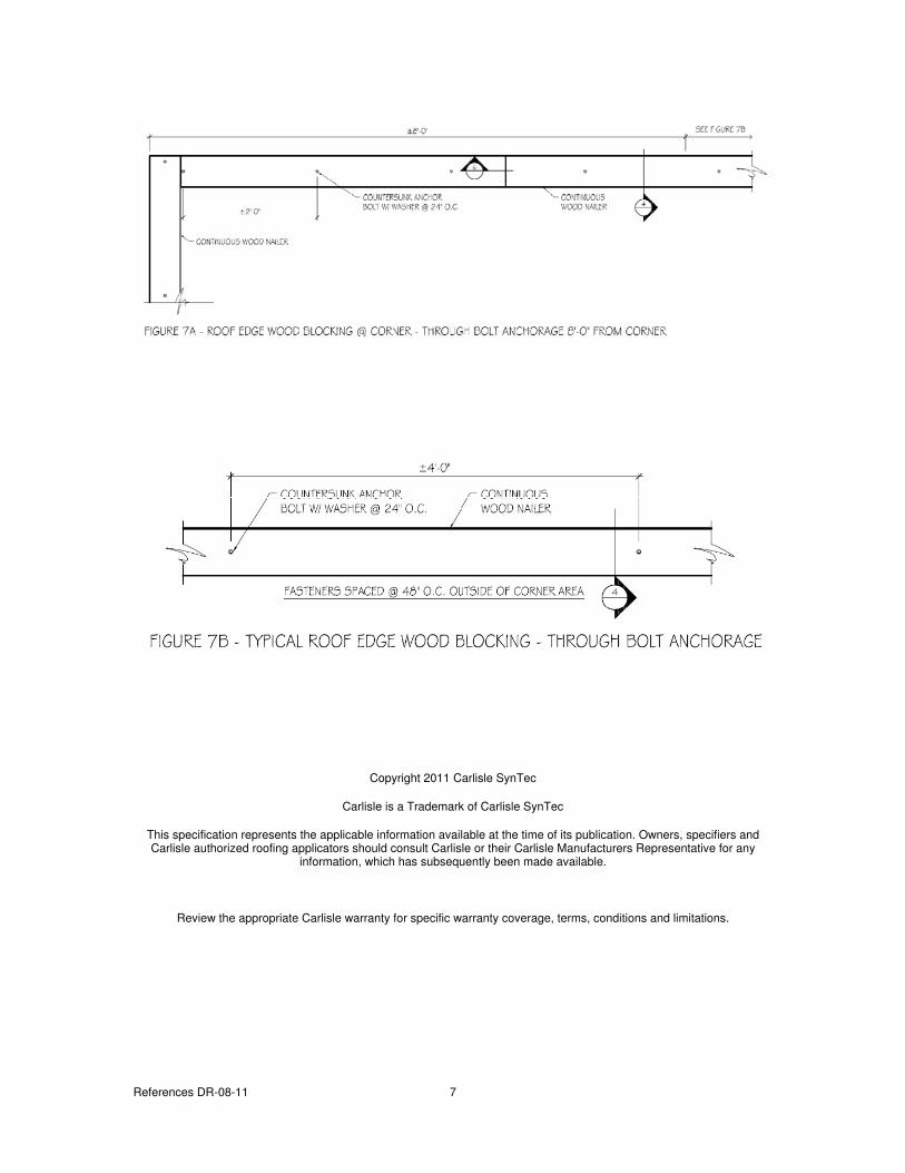
Projects requiring 75-psf or 90-psf ratings - fill the entire top course. Projects requiring 60-psf ratings - fill only required where anchor bolts are positioned (48 inches on center in the field, 24 inches on center at roof corners). At outside corners, the fastening density must be increased within the first 8 feet in each direction by positioning anchor bolts 24 inches on center. An alternate method may be used by installing 3/8 inch diameter anchor bolts spaced 32 inches apart. For outside corners, bolts are fastened 16 inches apart, 8 feet from each side of the corner. If additional wood nailers are needed, refer to Figure 5 for attachment of additional wood nailers.
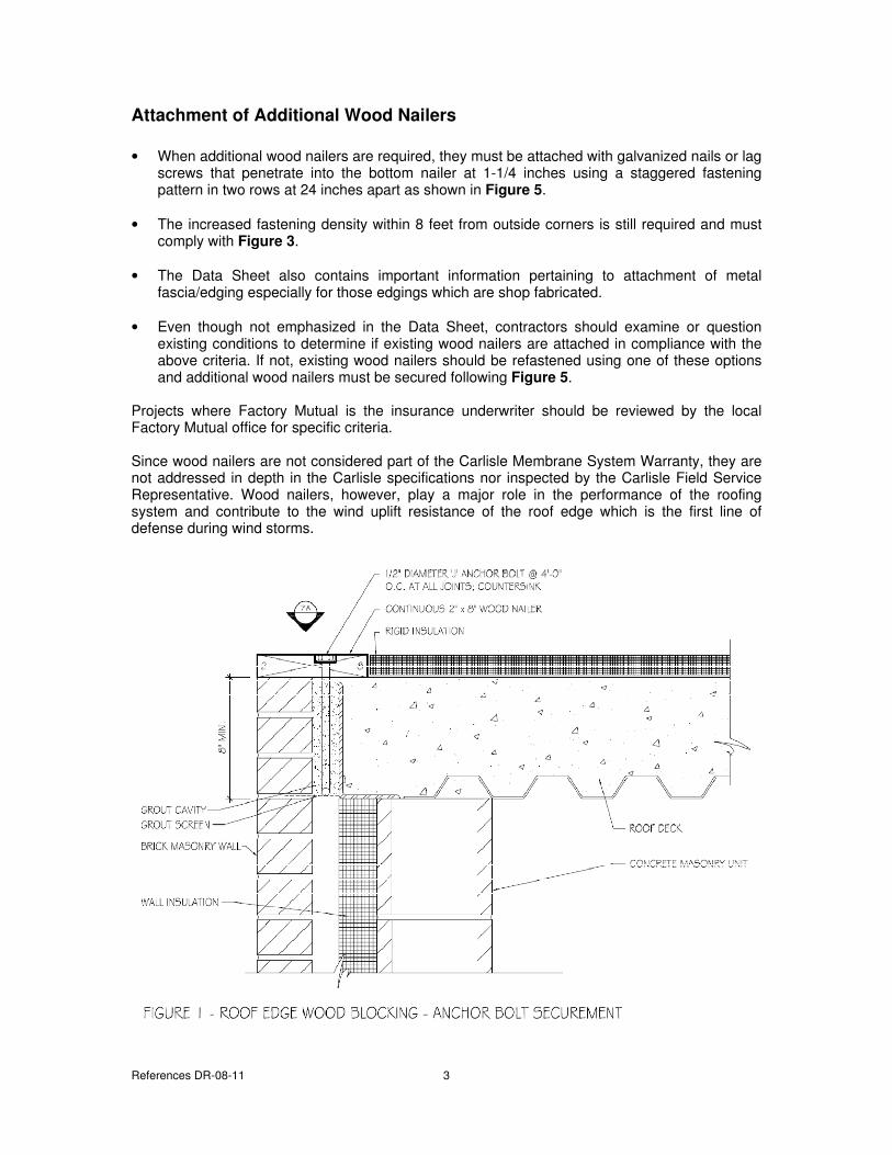
Attachment to Steel and Wood Decking
• Penetration of the fasteners should be to the top flutes only. The fasteners must be staggered as shown in Figure 2.
• The staggered fastening pattern should be increased within 8 feet from outside corners as shown in Figure 3A.
• If the perimeter nailer is to be secured to a steel angle, anchor bolts must be positioned at 48 inch centers as show in Figure 4.
• On wood decks, the staggered fastening pattern with galvanized steel screws should be utilized as shown in Figure 2.
Caution: Attention should be paid to the FMG requirement which calls for galvanized steel washers (minimum 5/8 inch outside diameter) to be used in conjunction with galvanized screws. This requirement is not recognized in most cases and most often forgotten.
References DR-08-11 3
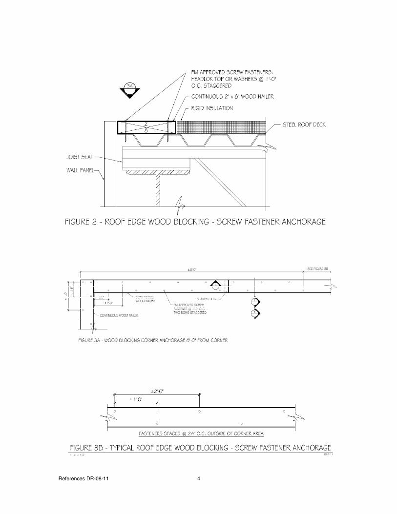
Attachment of Additional Wood Nailers
• When additional wood nailers are required, they must be attached with galvanized nails or lag screws that penetrate into the bottom nailer at 1-1/4 inches using a staggered fastening pattern in two rows at 24 inches apart as shown in Figure 5.
• The increased fastening density within 8 feet from outside corners is still required and must comply with Figure 3.
• The Data Sheet also contains important information pertaining to attachment of metal fascia/edging especially for those edgings which are shop fabricated.
• Even though not emphasized in the Data Sheet, contractors should examine or question existing conditions to determine if existing wood nailers are attached in compliance with the above criteria. If not, existing wood nailers should be refastened using one of these options and additional wood nailers must be secured following Figure 5.
Projects where Factory Mutual is the insurance underwriter should be reviewed by the local Factory Mutual office for specific criteria. Since wood nailers are not considered part of the Carlisle Membrane System Warranty, they are not addressed in depth in the Carlisle specifications nor inspected by the Carlisle Field Service Representative. Wood nailers, however, play a major role in the performance of the roofing system and contribute to the wind uplift resistance of the roof edge which is the first line of defense during wind storms.
References DR-08-11 4
References DR-08-11 5
References DR-08-11 6
References DR-08-11 7
Copyright 2011 Carlisle SynTec
Carlisle is a Trademark of Carlisle SynTec
This specification represents the applicable information available at the time of its publication. Owners, specifiers and Carlisle authorized roofing applicators should consult Carlisle or their Carlisle Manufacturers Representative for any
information, which has subsequently been made available.
Review the appropriate Carlisle warranty for specific warranty coverage, terms, conditions and limitations.
DR-09-11
Considerations for Hail Design
November 2011
The information contained represents guidelines to address possible requirements as part of the building specification as listed under the Quality Assurance or Performance Article. Carlisle recommends that the building owner retain a design professional to verify that these guidelines are appropriate.
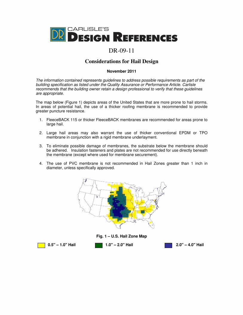
The map below (Figure 1) depicts areas of the United States that are more prone to hail storms. In areas of potential hail, the use of a thicker roofing membrane is recommended to provide greater puncture resistance.
1. FleeceBACK 115 or thicker FleeceBACK membranes are recommended for areas prone to
large hail.
2. Large hail areas may also warrant the use of thicker conventional EPDM or TPO membrane in conjunction with a rigid membrane underlayment.
3. To eliminate possible damage of membranes, the substrate below the membrane should
be adhered. Insulation fasteners and plates are not recommended for use directly beneath the membrane (except where used for membrane securement).
4. The use of PVC membrane is not recommended in Hail Zones greater than 1 inch in
diameter, unless specifically approved.
Fig. 1 – U.S. Hail Zone Map
0.5" – 1.0" Hail 1.0" – 2.0" Hail 2.0" – 4.0" Hail
Reference DR-09-11 2
Warranty
A. A warranty covering leaks caused by hail, maximum 1" diameter with FleeceBACK 100 or
105-mil membrane and maximum 2" diameter with FleeceBACK 115-mil (EPDM or TPO) or 135-mil (PVC) and maximum 3” diameter 135-mil (TPO) or 145-mil (EPDM) membrane, can be issued. Contact Carlisle for specific information. An additional 1” of hail coverage is available when Flexible FAST adhesive in full coverage or extrusions at 4” on center is utilized with EPDM or TPO FleeceBACK.
B. On projects utilizing FleeceBACK 115 membrane, a 5, 10, 15, or 20-year warranty with limited coverage for accidental punctures (up to 16 man-hours per year) is available. An additional 4 man-hours per year can be obtained when using Flexible FAST Adhesive in full coverage spray or extrusions at 4” on center.
C. On projects utilizing FleeceBACK 135 or 145 membrane, a 5, 10, 15, 20, 25 or 30-year warranty with limited coverage for accidental punctures (up to 32 man-hours per year) is available for an additional charge. An additional 4 man-hours per year can be obtained when using Flexible FAST Adhesive in full coverage spray or extrusions at 4” on center.
Copyright 2011 Carlisle SynTec Carlisle and FIeeceBACK are Trademarks of Carlisle SynTec
This specification represents the applicable information available at the time of its publication. Owners, specifiers and Carlisle authorized roofing applicators should consult Carlisle or their Carlisle Manufacturers Representative for any
information, which has subsequently been made available.
Review the appropriate Carlisle warranty for specific warranty coverage, terms, conditions and limitations.
DR-12-11
Metal Edging
November 2011
The information contained represents guidelines to address possible requirements as part of the building specification as listed under the Quality Assurance or Performance Article. Carlisle recommends that the building owner retain a design professional to verify that these guidelines are appropriate.
Pre-Manufactured vs. Shop Fabricated Metal
Introduction
The devastation caused by major hurricanes in Florida as well as the destruction of New Orleans and a portion of the Gulf Coast from Hurricanes Katrina and Rita serve as important reminders of the importance of a strong, impermeable roofing system.
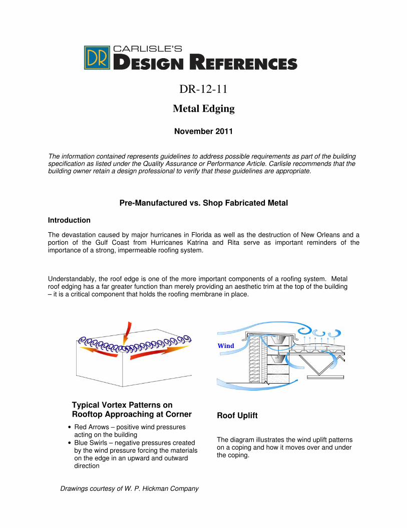
Understandably, the roof edge is one of the more important components of a roofing system. Metal roof edging has a far greater function than merely providing an aesthetic trim at the top of the building – it is a critical component that holds the roofing membrane in place.
Typical Vortex Patterns on
Rooftop Approaching at Corner
• Red Arrows – positive wind pressures acting on the building
• Blue Swirls – negative pressures created by the wind pressure forcing the materials on the edge in an upward and outward direction
Drawings courtesy of W. P. Hickman Company
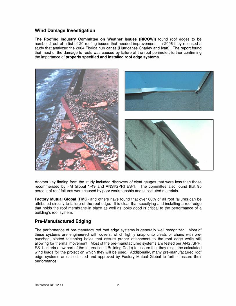
Roof Uplift
The diagram illustrates the wind uplift patterns on a coping and how it moves over and under the coping.
Wind
Reference DR-12-11 2
Wind Damage Investigation
The Roofing Industry Committee on Weather Issues (RICOWI) found roof edges to be number 2 out of a list of 20 roofing issues that needed improvement. In 2006 they released a study that analyzed the 2004 Florida hurricanes (Hurricanes Charley and Ivan). The report found that most of the damage to roofs was caused by failure at the roof perimeter, further confirming the importance of properly specified and installed roof edge systems.
Another key finding from the study included discovery of cleat gauges that were less than those recommended by FM Global 1-49 and ANSI/SPRI ES-1. The committee also found that 95 percent of roof failures were caused by poor workmanship and substituted materials.
Factory Mutual Global (FMG) and others have found that over 80% of all roof failures can be attributed directly to failure of the roof edge. It is clear that specifying and installing a roof edge that holds the roof membrane in place as well as looks good is critical to the performance of a building’s roof system.
Pre-Manufactured Edging
The performance of pre-manufactured roof edge systems is generally well recognized. Most of these systems are engineered with covers, which tightly snap onto cleats or chairs with pre-punched, slotted fastening holes that assure proper attachment to the roof edge while still allowing for thermal movement. Most of the pre-manufactured systems are tested per ANSI/SPRI ES-1 criteria (now part of the International Building Code) to assure that they resist the calculated wind loads for the project on which they will be used. Additionally, many pre-manufactured roof edge systems are also tested and approved by Factory Mutual Global to further assure their performance.
Reference DR-12-11 3
ES-1 Wind Design Standard for Edge Systems Used with Low Slope Roofing
Systems
In 1998 SPRI (Single Ply Roofing Industry, a roofing industry trade association) developed a series of three tests for judging the quality and durability of fascia and coping systems under the ES-1, an edge standard for low-slope roofs. The ES-1 was developed to aid architects, specifiers, and other roofing professionals in ensuring that a quality roof edge is specified and installed.
ES-1 was accepted by the American National Standard Institute (ANSI) as a standard and in 2002 the IBC (International Building Code) included the ES-1 guidelines into their code. With its inclusion with in the 2003 IBC, ES-1 has now become building code and a majority of the United States has adopted some version of the IBC. Delaware, Missouri and Nebraska have adopted versions of IBC but may on a Local Government level, refer to the Authority Having Jurisdiction (AHJ) in those states.
So designing a roof edge system that meets ANSI/SPRI ES-1 Wind Design Standard is not just a good idea; it is the law in many states.
The main reason for the development of ES-1 was to improve the longevity and safety of low-slope commercial roofs, to protect the building owner’s investment by reducing the risk of edge failure, and consequentially roof failure. Basically, ES-1 provides formulas for calculating the wind load on edges of low-slope roofs and prescribes methodology for testing and evaluating the ability of edge systems to withstand those loads; as a result this ensures wind resistance and long-term performance.
The ANSI/SPRI ES-1 standard is comprised of three pull-off tests (two tests for fascia and one test for coping) and they are based on the American Society of Civil Engineers’ document ASCE-7/02 – Minimum Design Loads for Buildings and Other Structures.
• Test Method RE-1 measures how well the edge secures the perimeter on ballasted and mechanically attached membranes.
• Test Method ES-2 is a pull-off test for the metal edge flashing. It tests for wind load on the face dimension of the flashing system.
• Test Method ES-3 tests the strength of the metal coping cap to assure it meets of exceeds calculated design wind pressure. It tests wind load on both the top and back leg dimensions.
How the test is performed – The tests use a pull/release and pull/release method rather than one continuous pull. This allows for a realistic simulation of wind, which acts on a building in periodic gusts rather than one long, continuous gust.
Reference DR-12-11 4
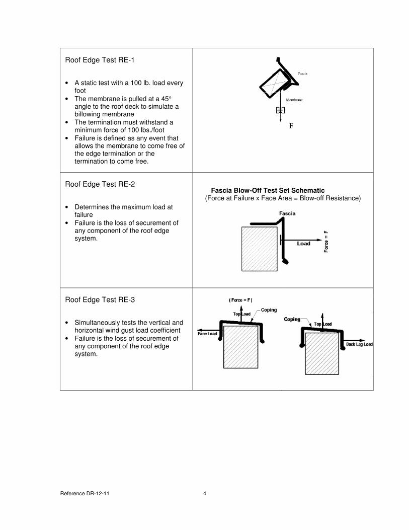
Roof Edge Test RE-1
• A static test with a 100 lb. load every foot
• The membrane is pulled at a 45° angle to the roof deck to simulate a billowing membrane
• The termination must withstand a minimum force of 100 lbs./foot
• Failure is defined as any event that allows the membrane to come free of the edge termination or the termination to come free.
Roof Edge Test RE-2
• Determines the maximum load at failure
• Failure is the loss of securement of any component of the roof edge system.
Fascia Blow-Off Test Set Schematic
(Force at Failure x Face Area = Blow-off Resistance)
Roof Edge Test RE-3
• Simultaneously tests the vertical and horizontal wind gust load coefficient
• Failure is the loss of securement of any component of the roof edge system.
Reference DR-12-11 5
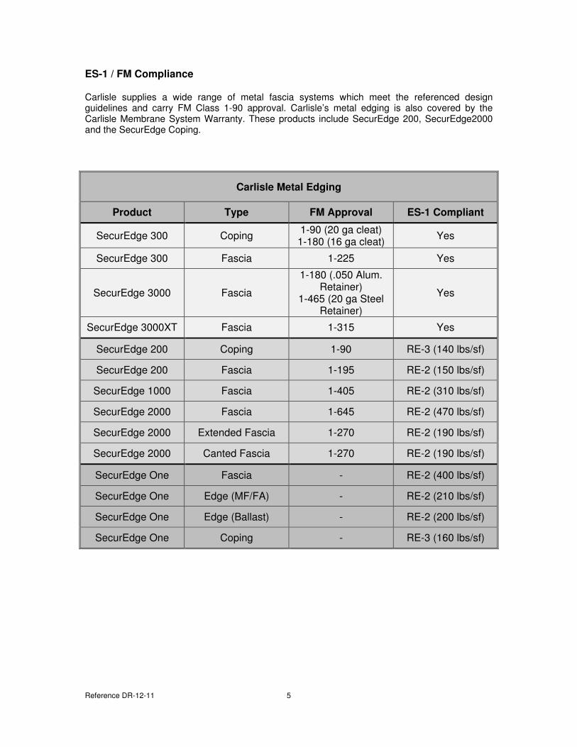
ES-1 / FM Compliance
Carlisle supplies a wide range of metal fascia systems which meet the referenced design guidelines and carry FM Class 1-90 approval. Carlisle’s metal edging is also covered by the Carlisle Membrane System Warranty. These products include SecurEdge 200, SecurEdge2000 and the SecurEdge Coping.
Carlisle Metal Edging
Product Type FM Approval ES-1 Compliant
SecurEdge 300 Coping 1-90 (20 ga cleat)
1-180 (16 ga cleat) Yes
SecurEdge 300 Fascia 1-225 Yes
SecurEdge 3000 Fascia
1-180 (.050 Alum. Retainer)
1-465 (20 ga Steel Retainer)
Yes
SecurEdge 3000XT Fascia 1-315 Yes
SecurEdge 200 Coping 1-90 RE-3 (140 lbs/sf)
SecurEdge 200 Fascia 1-195 RE-2 (150 lbs/sf)
SecurEdge 1000 Fascia 1-405 RE-2 (310 lbs/sf)
SecurEdge 2000 Fascia 1-645 RE-2 (470 lbs/sf)
SecurEdge 2000 Extended Fascia 1-270 RE-2 (190 lbs/sf)
SecurEdge 2000 Canted Fascia 1-270 RE-2 (190 lbs/sf)
SecurEdge One Fascia - RE-2 (400 lbs/sf)
SecurEdge One Edge (MF/FA) - RE-2 (210 lbs/sf)
SecurEdge One Edge (Ballast) - RE-2 (200 lbs/sf)
SecurEdge One Coping - RE-3 (160 lbs/sf)
Reference DR-12-11 6
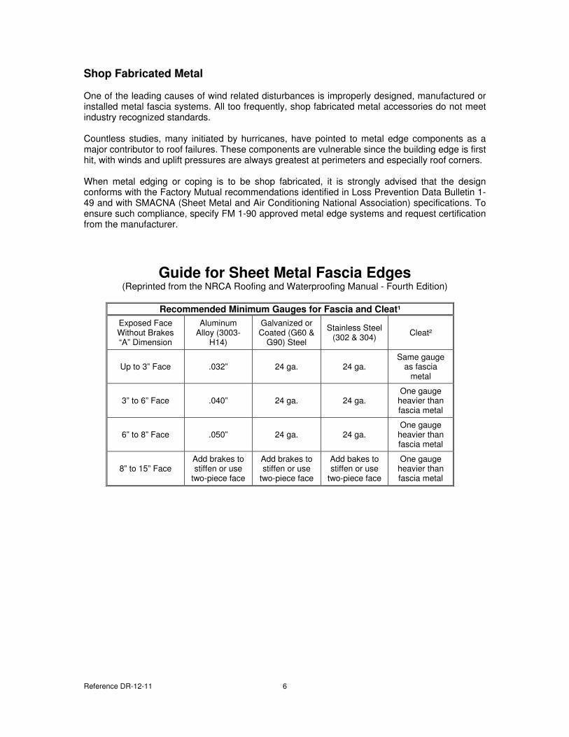
Shop Fabricated Metal
One of the leading causes of wind related disturbances is improperly designed, manufactured or installed metal fascia systems. All too frequently, shop fabricated metal accessories do not meet industry recognized standards. Countless studies, many initiated by hurricanes, have pointed to metal edge components as a major contributor to roof failures. These components are vulnerable since the building edge is first hit, with winds and uplift pressures are always greatest at perimeters and especially roof corners. When metal edging or coping is to be shop fabricated, it is strongly advised that the design conforms with the Factory Mutual recommendations identified in Loss Prevention Data Bulletin 1-49 and with SMACNA (Sheet Metal and Air Conditioning National Association) specifications. To ensure such compliance, specify FM 1-90 approved metal edge systems and request certification from the manufacturer.
Guide for Sheet Metal Fascia Edges (Reprinted from the NRCA Roofing and Waterproofing Manual - Fourth Edition)
Recommended Minimum Gauges for Fascia and Cleat¹
Exposed Face Without Brakes “A” Dimension
Aluminum Alloy (3003-
H14)
Galvanized or Coated (G60 &
G90) Steel
Stainless Steel (302 & 304)
Cleat²
Up to 3” Face .032” 24 ga. 24 ga. Same gauge
as fascia metal
3” to 6” Face .040” 24 ga. 24 ga. One gauge
heavier than fascia metal
6” to 8” Face .050” 24 ga. 24 ga. One gauge
heavier than fascia metal
8” to 15” Face Add brakes to stiffen or use
two-piece face
Add brakes to stiffen or use
two-piece face
Add bakes to stiffen or use
two-piece face
One gauge heavier than fascia metal
Reference DR-12-11 7
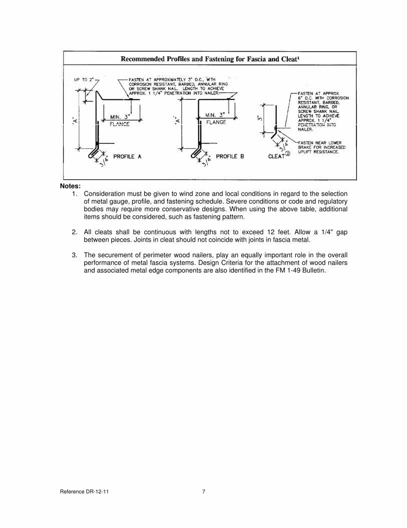
Notes:
1. Consideration must be given to wind zone and local conditions in regard to the selection of metal gauge, profile, and fastening schedule. Severe conditions or code and regulatory bodies may require more conservative designs. When using the above table, additional items should be considered, such as fastening pattern.
2. All cleats shall be continuous with lengths not to exceed 12 feet. Allow a 1/4" gap
between pieces. Joints in cleat should not coincide with joints in fascia metal.
3. The securement of perimeter wood nailers, play an equally important role in the overall performance of metal fascia systems. Design Criteria for the attachment of wood nailers and associated metal edge components are also identified in the FM 1-49 Bulletin.
Reference DR-12-11 8
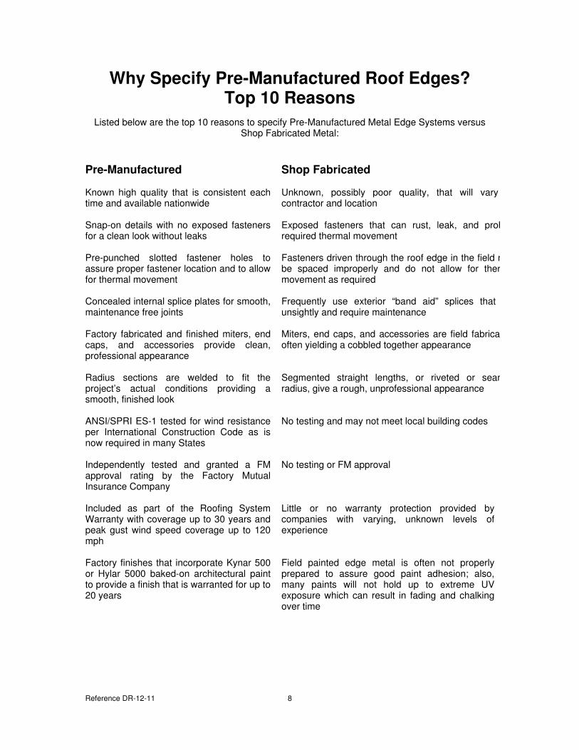
Why Specify Pre-Manufactured Roof Edges?
Top 10 Reasons
Listed below are the top 10 reasons to specify Pre-Manufactured Metal Edge Systems versus Shop Fabricated Metal:
Pre-Manufactured Shop Fabricated
Known high quality that is consistent each time and available nationwide
Unknown, possibly poor quality, that will vary by contractor and location
Snap-on details with no exposed fasteners for a clean look without leaks
Exposed fasteners that can rust, leak, and prohibit required thermal movement
Pre-punched slotted fastener holes to assure proper fastener location and to allow for thermal movement
Fasteners driven through the roof edge in the field may be spaced improperly and do not allow for thermal movement as required
Concealed internal splice plates for smooth, maintenance free joints
Frequently use exterior “band aid” splices that are unsightly and require maintenance
Factory fabricated and finished miters, end caps, and accessories provide clean, professional appearance
Miters, end caps, and accessories are field fabricated; often yielding a cobbled together appearance
Radius sections are welded to fit the project’s actual conditions providing a smooth, finished look
Segmented straight lengths, or riveted or seamed radius, give a rough, unprofessional appearance
ANSI/SPRI ES-1 tested for wind resistance per International Construction Code as is now required in many States
No testing and may not meet local building codes
Independently tested and granted a FM approval rating by the Factory Mutual Insurance Company
No testing or FM approval
Included as part of the Roofing System Warranty with coverage up to 30 years and peak gust wind speed coverage up to 120 mph
Little or no warranty protection provided by companies with varying, unknown levels of experience
Factory finishes that incorporate Kynar 500 or Hylar 5000 baked-on architectural paint to provide a finish that is warranted for up to 20 years
Field painted edge metal is often not properly prepared to assure good paint adhesion; also, many paints will not hold up to extreme UV exposure which can result in fading and chalking over time
Reference DR-12-11 9
Copyright 2011 Carlisle SynTec
Carlisle and SecurEdge are Trademarks of Carlisle SynTec
Kynar is a Trademark of Arkema Inc.
This specification represents the applicable information available at the time of its publication. Owners, specifiers and Carlisle authorized roofing applicators should consult Carlisle or their Carlisle Manufacturers Representative for any
information, which has subsequently been made available.
Review the appropriate Carlisle warranty for specific warranty coverage, terms, conditions and limitations.