Embed Size (px)
Citation preview

ABKE – Driver Version 2.25
Doc. Revision X – April 17, 2006
Page 1/27
Communication Driver ABKE
Driver for Serial Communication with AB Devices Using DF1 Protocol
Table of Contents
INTRODUCTION ................................................................................................................................................................2
GENERAL CHARACTERISTICS.......................................................................................................................................3
DEVICE CHARACTERISTICS.............................................................................................................................................. 3
LINK CHARACTERISTICS .................................................................................................................................................. 3
DRIVER CHARACTERISTICS.............................................................................................................................................. 4
CONFORMANCE TESTING ................................................................................................................................................ 5
INSTALLING THE DRIVER ...............................................................................................................................................6
CONFIGURING THE DEVICE ...........................................................................................................................................7
CONFIGURING THE DRIVER ...........................................................................................................................................7
SETTING THE COMMUNICATION PARAMETERS .................................................................................................................. 7
CONFIGURING THE STANDARD DRIVER WORKSHEET ...................................................................................................... 10
Configuring the Station and Header Fields .............................................................................................................. 11
Configuring the Address Field.................................................................................................................................. 12
CONFIGURING THE MAIN DRIVER SHEET (MDS) ....................................................................................................... 15
EXECUTING THE DRIVER..............................................................................................................................................17
TROUBLESHOOTING .....................................................................................................................................................18
USING THE APPLICATION SAMPLE ............................................................................................................................20
REVISION HISTORY .......................................................................................................................................................21
APPENDIX: SETTING UP PLC COMMUNICATION USING ROCKWELL RSLOGIX SOFTWARE .............................22

ABKE – Driver Version 2.25
Doc. Revision X – April 17, 2006
Page 2/27
Introduction
The ABKE driver enables communication between the Studio system and some of the Allen Bradley devices using the DF1 protocol, if these components comply with the characteristics described in this document. You can use the ABKE driver to exchange data with PLCs through a DH+ network using the appropriate DF1�DH+ gateway. This document was designed to help you install, configure, and execute the ABKE driver to enable serial communication with Allen Bradley devices. The information is organized, as follows:
� Chapter 1 Introduction: Provides an overview of the ABKE driver documentation.
� Chapter 2 General Characteristics: Describes all of the required hardware and software components you need to implement serial communication between the driver and the Allen Bradley devices. This chapter also discusses global characteristics about the communication.
� Chapter 3 Installing the Driver: Explains how to install the hardware and software components required for the ABKE driver.
� Chapter 4 Configuring the Device: Explains how to configure AB devices using the DF1 protocol.
� Chapter 5 Configuring the Driver: Explains how to configure the communication driver, including the different permutations for configuration and the driver’s default values.
� Chapter 6 Executing the Driver: Explains how to execute the driver to verify that you installed and configured the driver correctly.
� Chapter 7 Troubleshooting: Lists the most common error codes for this protocol and explains how to fix the errors.
� Chapter 8 Using the Application Sample: Provides a sample application, which you can use to test the driver configuration.
� Chapter 9 Revision History: Provides a log of all modifications made to the driver.
� Appendix: Setting Up the PLC Communication with the Manufacturer Programming Software: Explains how to use Rockwell RSLogix software to ensure that the PLC, connections, and cables are functioning properly before using Studio.
� Note: This document assumes that you have read the “Driver Configuration” chapter of the Studio Technical Reference Manual.
This document also assumes that you are familiar with the Windows NT/2000 environment. If you are unfamiliar with Windows NT/2000, we suggest using the Help feature (available from the Windows desktop Start menu) as you work through this guide.

ABKE – Driver Version 2.25
Doc. Revision X – April 17, 2006
Page 3/27
General Characteristics
This chapter discusses the characteristics of the hardware and software components used to implement communication between Allen Bradley devices and the ABKE driver. In addition, this chapter provides information about the equipment used for conformance testing. The chapter is organized as follows: � Device Characteristics � Link Characteristics � Driver Characteristics � Conformance Testing
Device Characteristics
To establish serial communication with the ABKE driver, you must use devices with the following specifications: � Manufacturer: Allen Bradley � Compatible Equipment:
- PLC5 series - PLC2 series - SLC500 - MicroLogix 1000/1200/1500 (compatible with SLC500 series)
� Rockwell PLC Programmer Software:
- RSLogix - ASP - RS6200
�Tip: Refer to the “Conformance Testing” section to review the equipment used in the standard conformance tests for this driver.
Link Characteristics
To establish serial communication between Allen Bradley devices and the ABKE driver, you must follow these specifications: � Device Communication Port: Serial DF1 port � Physical Protocol: Serial RS232 � Logic Protocol: DF1 � Device Runtime Software: None � Specific PC Board: None � Cable: Allen Bradley 1756CP3A/A01 S760 KSM

ABKE – Driver Version 2.25
Doc. Revision X – April 17, 2006
Page 4/27
Driver Characteristics
The ABKE driver is composed of the following files: � ABKE.INI: Internal file of the driver. You must not modify this file. � ABKE.MSG: Error messages for each error code. You must not modify this file. � ABKE.PDF: Document providing detailed information about the ABKE driver. � ABKE.DLL: Compiled driver.
� Notes: All of the preceding files have been installed in the /DRV subdirectory of the Studio installation directory.
You must use Adobe Acrobat Reader (provided with the Studio installation package) to view the ABKE.PDF document.
You can use the ABKE driver on the following operating systems:
- Windows 2000/XP - Windows NT - Windows CE ( x86 / SH3 / SH4 / MIPs / ARM / PPC )
�Tip: Refer to the “Conformance Testing” section to review the operating systems used in the standard conformance tests for this driver.
This driver supports the following Register types:
Register Type Length Write Read Bit Integer Float String
O (Output) 1 Byte • • • • − −
I (Input) 1 Byte − • • • − −
S (Status) 2 Bytes − • • • − −
B (Binary) 1 Byte − • • • − −
T (Timer) 6 Bytes • • − − − −
C (Counter) 6 Bytes • • − − − −
R (Control) 6 Bytes • • − − − −
F (Float) 4 Bytes • • − − • −
N (Integer File) 2 Bytes • • • • − −
A (ASCII File) 2 Bytes • • − • − •
ST (String File) N Bytes • • − − − •

ABKE – Driver Version 2.25
Doc. Revision X – April 17, 2006
Page 5/27
Conformance Testing
The following equipment was used for the conformance testing: � Equipment: PLC5/40 and SLC500/03 � Configuration:
- Baud Rate: 19200 - Protocol: DF1 - Data Bits: 8 - Stop Bits: 1 - COM port: COM1
� Cable: According to specifications described in the “Link Characteristics” section � Operating System (development): Windows XP � Operating System (target):
- Windows XP/2000 - Windows CE v4.2
� Studio Version: 6.1 � Driver Version: 2.25

ABKE – Driver Version 2.25
Doc. Revision X – April 17, 2006
Page 6/27
Installing the Driver
When you install Studio v3.0 and higher, all of the communication drivers are installed automatically. You must select the driver that is appropriate for the applications you are using. Perform the following steps to select the driver from within an application: 1. Execute Studio using one of the following methods:
� Double-click the Studio shortcut icon from the desktop. � Click on the Start menu, select Programs, and when the Studio Tools submenu displays, select Studio.
2. When the Studio window opens, open the appropriate application from the Workspace pane. 3. From the main menubar, select Driver… from the Insert menu to open the Communication drivers dialog box as
shown in the following figure.
4. Select the ABKE driver from the Available Drivers list and click the Select>> button. 5. When the ABKE driver displays in the Selected Drivers list, click the OK button to close the dialog. You are not required to install any other software on your computer to enable communication between Studio and the Allen Bradley device. However, you must install one of the Rockwell programmer software packages (such as RSLogix) to download the custom program to this device. Consult the Rockwell RSLogix documentation for a description of the procedure you must use to install their software.
�Caution: You must use special precautions when installing the physical hardware. Refer to the hardware manufacturer’s documentation for detailed instructions.

ABKE – Driver Version 2.25
Doc. Revision X – April 17, 2006
Page 7/27
Configuring the Device
You can use one of several methods for configuring the CPU serial channel. However, the default configuration for a PLC is as follows: � Baud Rate: 19200 � Data Bits: 8 � Stop Bits: 1 � Parity: None � Error Check: BCC
Configuring the Driver
After you install the ABKE driver and open Studio (as described in Chapter 3), you can configure the driver. You configure the driver in two stages: � You set the communication parameters (only one configuration for the whole driver). � You define the communication tags by completing the Driver Worksheets. There are two types of Driver
Worksheets:
- Standard Driver Worksheet - MAIN DRIVER SHEET (MDS)
The following sections provide instructions for setting the parameters and completing the worksheets.
Setting the Communication Parameters
When you set the communication parameters, they are valid for all Driver Worksheets configured in the system. Use the following steps to configure the communication parameters for the driver:
1. From the Studio application window, click the Comm tab located below the Workspace pane. 2. From the Workspace pane, expand the Drivers folder. 3. Right-click on the ABKE subfolder and when the pop-up menu displays, (as shown in the following figure)
select the Settings option.

ABKE – Driver Version 2.25
Doc. Revision X – April 17, 2006
Page 8/27
The Communication Parameters dialog displays as follows:
4. You must configure the following parameters:
Parameter Default Value
Valid Values Description
Station 0 0 Not required for this driver
Family PLC5
� 2 � 5 or 5:0 � 5:1 � 5x or � 500
AB PLC family (communicate with Studio’s driver) 2 - Driver ABTCP uses “unprotected read/write” DF1 command to communicate with PLC2 family. 5 or 5:0 - Driver ABTCP uses “typed read/write” DF1 command to communicate with PLC5 family. The address for any data type is decimal. 5:1 - Driver ABTCP uses “typed read/write” DF1 command to communicate with PLC5 family. The address for I and O data types is octal. The address for the remaining data types is decimal. 5x - Driver ABTCP uses “typed read/write” DF1 command to communicate with SoftPLC working like PLC5 family. 500 - Driver ABTCP uses “protected typed logical read/write” DF1 command to communicate with SLC500 family.
Error Check BCC BCC or CRC Defines the error check method that the driver will use
�Caution: It is strongly recommended that you configure value 5x in the Family field (instead of 5) when
using PLC5. This option uses commands that will increase the communication performance.
� Note: You must configure the Allen Bradley device with the same values defined for the ABKE driver in the
Communication Parameters dialog.

ABKE – Driver Version 2.25
Doc. Revision X – April 17, 2006
Page 9/27
5. Click on the Advanced… button in the Communication Parameters dialog. The Advanced settings dialog will display.
6. Use the following table to set the Control RTS (Request to Send) parameter.
Parameter Default Value
Valid Values Description
Control RTS No � no � yes � yes + echo
Define if the RTS handshake signal is set before communication and if there is an echo in the communication. � If you are using Windows 95 or CE with the correct
RS 232 – RS 485 Converter (without RTS Control), specify the no option.
� If you are using Windows NT with the Cutler Hammer RS 232 – RS 485 Adapter, you must specify the yes option.
Important: Setting this parameter incorrectly will prevent the driver from working and will generate a Timeout waiting to
start a message error message.
� Note: Although you can configure other serial communication parameters from this dialog, you should not change any of the default parameters at this time except Control RTS. The parameters on the Advanced settings dialog are explained in detail in the Studio Technical Reference Manual.
�Tip: Usually, you must change these parameters if you are using a DCE (Data Communication Equipment) converter (232/485, for example), modem, and so forth between the PC, driver, and the host. You must know the characteristics of the DCE before adjusting these parameters.

ABKE – Driver Version 2.25
Doc. Revision X – April 17, 2006
Page 10/27
Configuring the Standard Driver Worksheet
This section explains how to configure a Standard Driver Worksheet to define communication tags. You can configure multiple Driver Worksheets, each of which is divided into a Header and a Body. Use the following steps to create a new Standard Driver Worksheet:
1. From the Studio application window, select the Comm tab, located below the Workspace pane. 2. In the Workspace pane, expand the Drivers folder and right-click the ABKE subfolder. 3. When the pop-up menu displays (as shown in the following figure), select the Insert option.
�Tip: To optimize communication and ensure better performance for the system, it is important to group the tags in different driver sheets according to the events that trigger communication for each group of tags and to the periodicity for which each group of tags must be written or read. In addition, we recommend configuring the communication addresses into sequential blocks.
The ABKE001.drv worksheet displays (similar to the following figure).

ABKE – Driver Version 2.25
Doc. Revision X – April 17, 2006
Page 11/27
All fields on the Standard Driver Worksheet are standard for all communication drivers; except for the Station, Header, and Address fields. This document explains only the Station, Header, and Address fields because they are specific to each communication driver. For detailed information about the configuring of the standard fields refer to the Studio Technical Reference Manual. Proceed to the next section for an explanation about configuring the Station and Header fields. Configuring the Station and Header Fields This section explains the procedure for configuring the Station and Header fields. The following table describes the default and valid values for these two fields:
Parameter Default Value Valid Values Description
Station - 1 to 31 PLC’s Address
Header N7:0 See next table Defines the type of variable to be read or written from, or to, the device and references the initial address
When specifying the Header parameter, you must comply with the following syntax: � For Input and Output: <Type>:<SlotNumber>.0 (for example: O:1.0)
� For Status, Binary, Integer, Timer, Counter, and Control:
<Type><TypeGroup>:<AddressReference> (for example: N7:0)
� For Unsolicited Message: U:<TypeGroup> (for example: U:3)
Where:
- Type (Register Type): Type one of the following O=Output, I=Input, S=Status, B=Binary, N=File, T=Timer,
C=Counter, R=Control, F=Float, A=ASCII, ST=String. - SlotNumber: Type the I/O Card Slot Number. - TypeGroup: Type the Group Number of the register type you configured. - AddressReference: Type the Initial Address (reference) of the group you configured.
After you edit the Header field, the system checks that the syntax is valid. If the syntax is incorrect, the system automatically inserts the default value (N7:0) into the Header field.

ABKE – Driver Version 2.25
Doc. Revision X – April 17, 2006
Page 12/27
If you type a Tag string between curly brackets {Tag} into this field, you must ensure that the Tag value and syntax
are both correct or an Invalid Header error will result. The following table describes the proper syntax for both the
field type and the Tag value.
Information about the Header Parameter
Field Type Syntax Sample
Valid Range for Initial Address
Comments
Output O:0.0 Varies according to
the equipment
Physical outputs: Where “O” means output. The first digit after the colon defines the word number if there is more than one digit in the same slot and the first digit following the dot is the output address.
Input I:0.0 Varies according to
the equipment
Physical inputs: Where “I” means input. The first digit after the colon defines the word’s number if there’s more than one digit in the same slot and the digit following the dot is the output address.
Status S:0 Varies according to
the equipment Reads the status words.
Binary B3:0 0 to 255 Reads the binary operator.
Integer N7:0 0 to 255 Reads and Writes the Integer addresses.
Timer T4:0 0 to 255 Reads and Writes the Timer addresses.
Counter C5:0 0 to 255 Reads and Writes the Counter addresses.
Control R6:0 0 to 255 Reads and Writes the Control addresses.
Float F8:0 0 to 255 Reads and Writes the Float addresses.
ASCII A14:0 0 to 255 Reads and Writes the ASCII addresses. SLC500: The “Address Reference” is defined in words. PLC5: The “Address Reference” is defined in bytes.
String ST15:0 0 to 255 Reads and Writes the String addresses.
Unsolicited Messages
U:0 0 to 999
If you program the PLC to send unsolicited messages to Studio, type U: in the Header field, followed by the name of the file that
you are sending. Important: The Unsolicited Messages field type has been tested with PLC2 only. See the following Note.
� Note: If you are using unsolicited messages, you must create a Driver Worksheet after programming the correct
files on the PLC. On the Driver Worksheet, you must specify the U: Header, followed by the file number. The file type
is not important, only the file number. Also, you must type the PLC address into the worksheet body instead of the offset value.
After specifying the Station and Header field parameters, proceed to the next section for instructions about configuring the Address field. Configuring the Address Field The body of the Driver Worksheet allows you to associate each tag to its respective address in the device. In the Tag Name column, you must type the tag from your application database. This tag receives or sends values from, or to, an address on the device. The address field must comply with the following syntax: � For Input and Outputs: <Format><OctetNumber>/<Bit> (for example: W0/3)
� For Status, Binary, and Integer: <Format><AddressOffset>/<Bit> (for example: W10/12)
� For Timer, Counter, and Control: <Format><AddressOffset>.<Element> (for example: W2.PRE) � For ASCII:
- <Format = ´S´><AddressOffset>.<Number of Bytes> (for example: S1.2)
- <Format><AddressOffset> (for example: W0)

ABKE – Driver Version 2.25
Doc. Revision X – April 17, 2006
Page 13/27
� For Unsolicited Message: <Format><Address> (for example: W2)
Where: � Format: Type
- W to treat the values as words
- B to treat the values as BCDs
- F to treat the values as Floats (double words)
- S to treat the values as Strings
� OctetNumber: Type the Octet Number of the I/O card you configured in the Header field. � AddressOffset: Add this parameter to the AddressReference (configured in the Header field) to compose the
address of the Group you configured in the Header field. � Number of Bytes: Specify the Maximum Size of an ASCII/STRING data type. � Address: Type the address of the Group you configured in the Header field. � Bit: Type the Bit Number (from 0 to 15) from the word address. (optional parameter) � Element: Specify the Element Type for Timers, Counters, and Controls according to the following table:
Elements Register
DN PRE ACC EN TT UA UN OV CD CU FD IN UL ER EM EU LEN POS
Timer • • • • • − − − − − − − − − − − − −
Counter • • • − − • • • • • − − − − − − − −
Control • − − • − − − − − − • • • • • • • •
�Caution: You can use the Bit Writing function only with the Write on tag change driver tag enabled, which
means that you cannot use the Write trigger tag for the Bit Writing function. This same rule applies to Timers,
Counters, and Controls registers.
�Caution: The Format B option (BCD) applies to the first 12 bits only. You can view the last 4 bits in the “Quality”
field. For example: When reading the TAG_N7[0] tag from the N7:0 address, the last 4 bits of this address are written
to the TAG_N7[0]->Quality field.
�Caution: For worksheets that handles ASCII data type (A type in the Header and S type in the Address fields) In PLC5 (assuming 5x was chosen in Family parameter) you’ll be using “Typed Read/Write” commands. With this command you may read starting from an odd address, but you cannot write to an odd address. The final address is given by the sum of the initial address in the Header field and the least address found in the Address column of the worksheet. When writing ASCII data type, be sure to write to even addresses.
Sample of Address Configuration Address on the Device Header Field Address Field
I:0/7 I:0.0 W0/7
I:0/10 I:0.0 W0/8
I:0/17 I:0.0 W0/15
I:0/25 I:1.0 W0/5
I:3/4 I:0.0 W3/4
I:3/4 I:0.3 W0/4
O:0/7 O:0.0 W0/7
O:0/10 O:0.0 W0/8
O:0/17 O:0.0 W0/15
O:0/25 O:1.0 W0/5
O:3/4 O:0.0 W3/4

ABKE – Driver Version 2.25
Doc. Revision X – April 17, 2006
Page 14/27
O:3/4 O:0.3 W0/4
S:0/5 S:0 W0/5
S:10/7 S:0 W10/7
S:10/7 S:10 W0/7
B3:0/5 B3:0 W0/5
B3:167 B3:0 W10/7
B3:10/7 B3:10 W0/7
N7:0 N7:0 W0
N7:0/10 N7:0 W0/10
N7:50 N7:20 W30
T4:0/ACC T4:0 W0/ACC
T4:0/PRE T4:0 W0/ACC
T15:0/EN T15:0 W0/EN
T15:0/ACC T14:0 W1/ACC
T15:1/ACC T14:0 W2/ACC
C5:0/ACC C5:0 W0/ACC
C5:1/PRE C5:0 W1/PRE
C20:15/UA C20:10 W5/UA
R6:0/LEN R6:0 W0/LEN
R6:0/POS R6:0 W0/POS
R6:1/POS R6:0 W1/POS
F8:0 F8:0 F0
F8:5 F8:5 F0
F8:5 F8:0 F5
A14:0 (default size: 2 bytes) A14:0 S0.2
A14:1 (default size: 2 bytes) A14:1 S0.2
A14:1 (default size: 2 bytes) A14:0 S1.2
A14:0 to A14:2 A14:0 S0.6
ST15:0 (String: maximum 20 bytes) ST15:0 S0.20
ST15:1 (String: maximum 50 bytes) ST15:0 S1.50
ST15:2 (String: maximum 10 bytes) ST15:1 S1.10
Unsolicited message N3:10 U:3 W10
Unsolicited message N3:20 U:3 W20
�Caution: You are not permitted to configure a range of addresses greater than the maximum block size (data buffer length) supported by each PLC (as follows) in the same worksheet:
� For PLC 2 and PLC 5 devices, the maximum data buffer length is 244 bytes. � For the SLC device family in the Read commands, the maximum data buffer length is 236 bytes (SLC/03 and
SLC/04) and 82 bytes (SLC5/01 and SLC5/02). � For the SLC device family in the Write commands, the maximum data buffer length is 234 bytes (SLC/03 and
SLC/04) and 82 bytes (SLC5/01 and SLC5/02).

ABKE – Driver Version 2.25
Doc. Revision X – April 17, 2006
Page 15/27
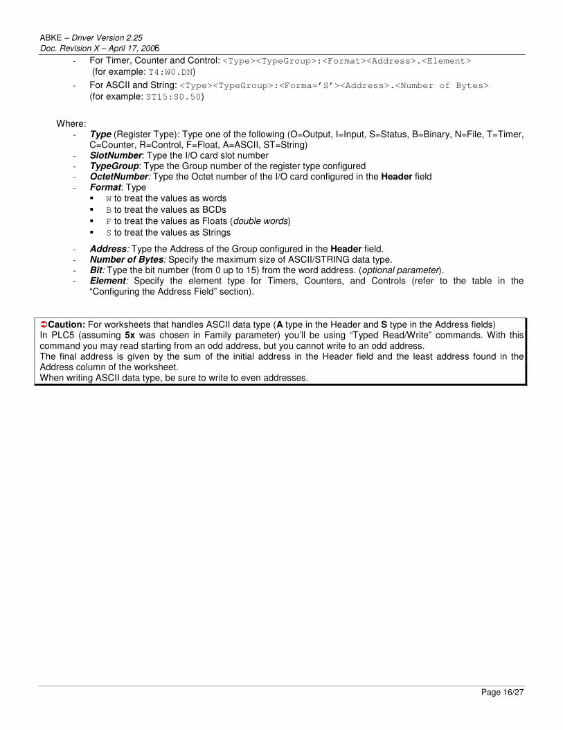
Configuring the MAIN DRIVER SHEET (MDS)
When you add the ABKE driver to your application, the program automatically adds the MAIN DRIVER SHEET (MDS) to the ABKE driver folder (refer to the following figure).
The MDS provides a simple way for you to associate Studio tags to addresses in the PLC. Most MDS entries are standard for any driver. For detailed information about configuring these standard entries, refer to the Studio Technical Reference Manual. 1. Double-click on the MAIN DRIVER SHEET icon to open the following worksheet:
2. Complete the fields on this dialog, being sure to comply with the following syntax:
� Station: PLC Address (ID number) � I/O Address: Address of each register from the PLC.
- For Input and Outputs: <Type>:<SlotNumber>.<Format><OctetNumber>/<Bit>
(for example: O:1.W2/4)
- For Status, Binary and Integer: <Type><TypeGroup>:<Format><Address>/<Bit>
(for example: N7:W150/2)
ABKE – Driver Version 2.25
Doc. Revision X – April 17, 2006
Page 16/27
- For Timer, Counter and Control: <Type><TypeGroup>:<Format><Address>.<Element>
(for example: T4:W0.DN)
- For ASCII and String: <Type><TypeGroup>:<Forma=’S’><Address>.<Number of Bytes>
(for example: ST15:S0.50)
Where:
- Type (Register Type): Type one of the following (O=Output, I=Input, S=Status, B=Binary, N=File, T=Timer, C=Counter, R=Control, F=Float, A=ASCII, ST=String)
- SlotNumber: Type the I/O card slot number - TypeGroup: Type the Group number of the register type configured - OctetNumber: Type the Octet number of the I/O card configured in the Header field - Format: Type
� W to treat the values as words
� B to treat the values as BCDs
� F to treat the values as Floats (double words)
� S to treat the values as Strings
- Address: Type the Address of the Group configured in the Header field. - Number of Bytes: Specify the maximum size of ASCII/STRING data type. - Bit: Type the bit number (from 0 up to 15) from the word address. (optional parameter). - Element: Specify the element type for Timers, Counters, and Controls (refer to the table in the
“Configuring the Address Field” section).
�Caution: For worksheets that handles ASCII data type (A type in the Header and S type in the Address fields) In PLC5 (assuming 5x was chosen in Family parameter) you’ll be using “Typed Read/Write” commands. With this command you may read starting from an odd address, but you cannot write to an odd address. The final address is given by the sum of the initial address in the Header field and the least address found in the Address column of the worksheet. When writing ASCII data type, be sure to write to even addresses.

ABKE – Driver Version 2.25
Doc. Revision X – April 17, 2006
Page 17/27
Executing the Driver
When you add the driver to a project, the system sets it automatically so the driver is ready to execute when you start-up the Runtime Environment. To verify that the driver is enabled and will start correctly, 1. Select Project from the main menubar, and then select the Status… option from the menu to verify the Driver
Runtime task.
The Project Status dialog box displays. .
If you click on (highlight) the Driver Runtime line (as shown in the preceding figure), the Startup… button becomes active. You can click on the Startup… button to switch between Automatic and Manual Startup mode.
ABKE – Driver Version 2.25
Doc. Revision X – April 17, 2006
Page 18/27
Troubleshooting
If the ABKE driver fails to communicate with the Allen Bradley device, the tag you configured for the Read Status or Write Status fields receives an error message. The error message contains an error code, which you can use to identify what type of failure occurred. The following table describes all of the error codes:
Error Code
Description Possible Causes Procedure to Solve
0 OK Communication without problems None required
1 Protocol error
� Wrong Family type specified for the Family field on the Communication Parameters dialog.
� Wrong cable or CPU in fault mode.
� Check PLC family specified in the Family field.
� Check cable. � Check CPU mode.
2 Block size error Offset specified for the Driver Configuration worksheet is too big and the message cannot be framed.
Change offsets or create a new worksheet.
3 Invalid family Wrong Family specified for the Family field.
Type correct PLC family.
10 Message sequence error
Error is another protocol error. Check CPU status (high probability of a CPU error).
16 Illegal command or format
Some element of the address specified for the Driver Configuration worksheet does not exist at the PLC.
Check PLC address and compare it with the Driver Worksheets.
20 Invalid address
� Timers, Counters, and Controls files were not specified in their correct fields in the Addresses column.
� Wrong address syntax specified for the other files.
Check Header field. � If you use a TAG, check whether the TAG
value is valid for the specified addresses. � If you did not use a TAG, you might have
changed the Header after configuring the Addresses and the addresses are invalid for the new Header.
30 Invalid header Wrong Header typed on the Driver Configuration worksheet.
Refer to the “Configuring the Station and Header Parameters” section for samples of valid Headers.
32 Host has a problem and cannot communicate
Verification errors within the host PLC processor.
Check entire driver and PLC configuration.
40
Remote node host is missing, disconnected, or shutdown
PLC is not connected, the node configuration is invalid, or in a shutdown process.
� Check the PLC state to ensure the processor is not at fault.
� Check to see if the cables are connected correctly.
50 Writing bit is not allowed via Write Trigger
Tag specified for the Write trigger field on a Driver Configuration worksheet was used for Writing Bit.
Check Write Target tag. Bit writing is allowed only if you use “Write on tag change.”
64
Host could not complete function due to hardware fault
Local PLC backplane error (either memory parity or timeout/disconnected) and PLC aborted the message execution.
� Check parity configuration for both PLC and Communication Parameters dialog.
� Verify that cables are connected properly.
80 Address problem or memory protect rungs
Attempt to access an illegal address in the PLC processor aborted message execution.
� Check that you configured the Family on Communication Parameters dialog.
� Check PLC address.

ABKE – Driver Version 2.25
Doc. Revision X – April 17, 2006
Page 19/27
96
Function not allowed due to command protection selection
Execution of a command at the PLC processor disabled by a switch option.
Check PLC to see if a command protection is specified. If so, disable it.
112 Processor is in Program mode
PLC is in Program or Remote program mode, or 1771-KA is in download mode.
Switch PLC mode to RUN.
128
Compatibility mode file missing or communication zone problem
Execution of protected commands at the PLC processor inhibited because PROG light is ON.
� See if PLC is on PROG mode. If so, change to RUN mode.
� Compare existing files to the configured files.
144 Remote node cannot buffer command
Driver error: invalid command. Contact Technical Support Staff.
150 Send File number error
� Studio system is sending a message and the PLC does not respond.
� The PLC responds that there is no file specified.
� Incorrectly specified station.
� Verify that required file exists. � Check Station field and PLC address.
176 Remote node problem due to download
PLC is under downloading action or last download generated a problem.
Try downloading PLC program again.
-15 Timeout waiting to start a message
� Disconnected cables � PLC turned off, or in Stop or Error
mode � Wrong station number � Wrong RTS/CTS configuration
settings
� Check cable wiring. � Ensure that the PLC state is RUN. � Check station number. � Verify that you are using the correct
configuration. Consult the “Link Characteristics” section for the valid RTS/CTS configuration settings.
-17 Timeout between rx char.
� PLC in stop or error mode � Wrong station number � Wrong parity � Wrong RTS/CTS configuration
settings
� Check cable wiring. � Ensure that PLC state is RUN. � Check station number. � Verify that you are using the correct
configuration. Consult the “Link Characteristics” section for valid RTS/CTS configuration settings.
�Tip: You can verify the communication status using the Studio environment Output window or the LogWin module. To establish an event log for Field Read Commands, Field Write Commands, and Serial Communication right-click on the Output window. When the pop-up menu displays, select the option to set the log events. If you are testing
under a Windows CE target, you can enable the log at the unit (Tools/Logwin) and verify the celog.txt file created
at the target unit.
If you are unable to establish communication with the PLC, you must first try to establish communication between the PLC Programming Tool and the PLC. Quite frequently, communication is not possible because you have a hardware or cable problem, or a PLC configuration error. After you successfully establish communication between the PLC Programming Software and the PLC, you can retest the supervisory driver. When testing communication with Studio, you should first try using the application sample in the next chapter (if the sample is available for the driver), instead of using the new application that you are creating. If you are unable to establish communication between the ABKE driver and the Allen Bradley devices, you can contact the Technical Support staff as described in the Studio Technical Reference Manual.

ABKE – Driver Version 2.25
Doc. Revision X – April 17, 2006
Page 20/27
Using the Application Sample
Studio provides a configured project that you can use to test the driver. We strongly recommend that you perform some tests with this application sample before configuring a customized project, for the following reasons: � To better understand the information discussed in this document. � To verify that your configuration is working. � To certify that the hardware used in the test (device + adapter + cable + PC) is in working condition before you
start configuring the application.
� Note: The Application Sample is not available for all drivers.
You will find the Studio application sample on the installation CD-ROM in the following directory:
\COMMUNICATION EXAMPLES\ABKE
To perform the test, you must follow these steps: 1. Configure the device communication parameters using the manufacturer programmer software. 2. Open the \COMMUNICATION EXAMPLES\ABKE application.
3. Execute the application. 4. Display the application screen (which includes some information about the communication) by executing the
Viewer module in Studio.
�Tip: You can use the application sample as a maintenance screen for the custom application.

ABKE – Driver Version 2.25
Doc. Revision X – April 17, 2006
Page 21/27
Revision History
Doc. Revision
Driver Version
Author Date Description of Changes
A 2.04 Roberto V. Junior Sep/30/1999 � First driver version � Driver available for Windows CE
B 2.05 Roberto V. Junior Jan/10/2000 Implemented SLC500 Bit Writing
C 2.06 Roberto V. Junior Apr/7/2000 Fixed “Timeout Between Rx char” error caused by bit write before first Read command.
D 2.07 Roberto V. Junior Jul/7/2000 � Write error when first address position is not zero. � Write error when addresses are out of sequence.
E 2.08 Roberto V. Junior Aug/2/2000 � Added CRC Check Error � Fixed bug in the Byte counter (timeout error)
F 2.09 Roberto V. Junior Aug/22/2000 Show Rx message in the LogWin.
G 2.10 Roberto V. Junior Oct/9/2000 Added MAIN DRIVER SHEET feature.
H 2.11 Roberto V. Junior Jan/1/2001 Added Timer, Counter, and Control operands.
I 2.12 Roberto V. Junior Mar/20/2001 Fixed configuration of I and O operand in the MAIN DRIVER SHEET.
J 2.13 Roberto V. Junior Mar/23/2001 Fixed problem caused by reading Timers with offsets greater than 0.
K 2.14 Roberto V. Junior Jun/26/2001 � Added Float-Pointer operand. � Fixed bug to wait device response.
L 2.15 Roberto V. Junior Jul/20/2001 Added ASCII operand.
M 2.16 Roberto V. Junior Jul/24/2001 Added String operand.
N 2.16 Fabíola Fantinato Nov/20/2001 Added Appendix A to the documentation.
O 2.17 Roberto V. Junior Feb/21/2002 � Documentation format and text revision. � Included “Typed Read/Write” commands to PLC5
family
P 2.18 Eric Vigiani Jun/5/2002 Modified internal algorithm to accept initial address higher than 255.
Q 2.20 Eric Vigiani Sep/30/2002 Modified header parse to accept any Type Group of the PLC 5 family
R 2.21 Lourenço Teodoro Aug/11/2003 Fixed GPF when the address configured in the Main Driver Sheet is invalid.
S 2.22 Fabio H. Y. Komura Feb/20/2004 Fixed error when configure several Float-Point data registers in the Main Driver Sheet.
T 2.23 Fabio H. Y. Komura Jul/15/2004
� Fixed problem with I/Os in family 5. � Included the option to choose the address for data
type as Octal or Decimal to PLC5. � Fixed problem when “Write with Header” offset is
different from 0 (zero).
U 2.23 Lourenço Teodoro Nov/23/2004 Updated the communication parameters window.
V 2.24 Eric Vigiani Apr/13/2005 Fixed problem in the read to PLC2 family
X 2.25 Diego Barros Apr/17/2005
� Fixed problem while reading Float operands. MDS and Standard sheets.
� Fixed problem on MDS - Timer and Counter Block Size.
� Fixed problem while writing strings to both MDS and SDS.

ABKE – Driver Version 2.25
Doc. Revision X – April 17, 2006
Page 22/27
Appendix: Setting Up PLC Communication Using Rockwell RSLogix Software
Rockwell RSLogix software is a workbench tool that you must use with RSLinx software to enable communication with the PLC.
� Note: Before attempting to establish communication with Studio, we recommend using the RSLogix software to set
up communication with a serial line to ensure that the PLC, connections, and cable are all working properly.
Use the following step-by-step procedure to set up communication with RSLogix using a serial line.
� Note: These instructions use PLC to refer to a SLC500 or a KE module. You must configure the device in the
appropriate field.
1. Connect your computer and the PLC through a serial cable. 2. Start the RSLinx software. 3. Select Communications from the Rockwell Software RSLinx Lite menubar, and then select Configure Drivers from the
menu (as shown in the following figure).

ABKE – Driver Version 2.25
Doc. Revision X – April 17, 2006
Page 23/27
4. When the Configure Drivers dialog displays, select RS-232 DF1 Devices from the Available Drivers list, and click the Add New… button.
5. The RS-232 DF1 Devices driver moves to the Configured Drivers list. Click the Close button to save your changes and
close the dialog box. 6. When the Configure Allen-Bradley DF1 Communications Device dialog displays, specify an appropriate Comm Port
and Device Type. 7. You can configure the remaining parameters on this dialog automatically by clicking the
Auto-Configure button. After a few moments, you should see the following message: Auto Configuration Successful!
If this message does not display, verify that the Comm Port and Device Type parameters are correct and then check that the cable is working properly.

ABKE – Driver Version 2.25
Doc. Revision X – April 17, 2006
Page 24/27
8. Click Ok to confirm your settings and close the dialog box. 9. Return to the main menubar. Select Communications and then select the SuperWho… option.
You should see the following window, which represents the PC Station 0 and the PLC Station 1 communicating.
10. Start the RSLogix software. 11. From the RSLogix main menubar, select the Comms option and then select System Comms….

ABKE – Driver Version 2.25
Doc. Revision X – April 17, 2006
Page 25/27
12. When the System Options dialog displays, click the System Communications tab. 13. In the Current settings section, select the AB_DF1-1 driver from the Driver drop-down list. 14. In the Processor Node text box, type the PLC station number: 1.
15. Click OK to close this dialog.
You should see the following screen in the RSLogix 500 window and the Revision Note dialog box:

ABKE – Driver Version 2.25
Doc. Revision X – April 17, 2006
Page 26/27
16. Select Comms from the main menubar, and then select Go Online.
If the RSLogix software is communicating successfully with the field device, you should see the following screen:

ABKE – Driver Version 2.25
Doc. Revision X – April 17, 2006
Page 27/27
At this point, you can start testing communication with the Studio software.