Embed Size (px)
Citation preview

TABLE OF CONTENTS LIST OF FIGURES..........................................................................................................2 LIST OF TABLES............................................................................................................2
1. MOTION CONTROL SOFTWARE OVERVIEW ................................................... 3
2. THE MOTION CONSOLE PROGRAM ................................................................... 5 2.1 BASE ADDRESS ................................................................................................................. 5 2.2 CONFIGURATION/TUNING ................................................................................................... 5 2.3 DEFAULT FILTER PARAMETERS .......................................................................................... 6 2.4 DC OFFSET PARAMETER ................................................................................................... 6
3. CONTROL PROGRAMS ........................................................................................... 8 3.1 HEADER FILE SUMMARY ................................................................................................... 8 3.1.1 Btech.h .............................................. 8 3.1.1.1 Important Constants ............................................................................................... 8 3.1.1.2 Structure Definitions .............................................................................................. 9 3.1.2 Syscfg.h ............................................ 10 3.1.3 Vars.h .............................................. 10 3.1.4 Ripple.h ............................................ 10 3.1.5 Globals.h ........................................... 11 3.2 BTECH.LIB SUMMARY ..................................................................................................... 11 3.2.1 General Utility Functions ........................... 11 3.2.2 Position Functions .................................. 11 3.2.3 Torque Functions .................................... 12 3.2.4 Torque Ripple Functions ............................. 13 3.2.5 General Robot Functions ............................. 14 3.2.6 Movement Functions .................................. 16 3.2.7 Point_List Functions ................................ 17 3.2.8 File Functions ...................................... 17 3.2.9 Awaken/Sleep Routines ............................... 18 3.3 ADDITIONAL PROGRAM SUMMARY ................................................................................... 18 3.3.1 Wamdemo.c Program ................................... 18 3.3.2 Trdaq.c Program ..................................... 24 3.3.3 Trtest.c Program .................................... 24
4. TORQUE RIPPLE COMPENSATION ................................................................... 26 4.1 ALGORITHM .................................................................................................................... 26 4.2 COMPENSATION ............................................................................................................... 27 4.3 TORQUE SCALING ........................................................................................................... 27 4.4 CONSIDERATIONS ............................................................................................................ 28
5. GRAVITY COMPENSATION ................................................................................. 29 5.1 THEORY ......................................................................................................................... 29 5.2 EXPERIMENTALLY DETERMINED MASS PARAMETERS ......................................................... 33
Barrett Technology, Inc.BA4-310 Software Manual Version 1.1
1

LIST OF FIGURES
FIGURE 1-MULTI-LAYER MOTION CONTROL STRUCTURE SCHEMATIC FOR THE BARRETTARM AND BARRETTWRIST PRODUCTS. .......................... 3
FIGURE 2: TYPICAL SMOOTH TORQUE RIPPLE DATA ................................... 26
FIGURE 3: BARRETTARM IN “HOME” POSITION WITH THE DENAVIT-HARTENBERG FRAMES AND PARAMETERS SHOWN. ..................................... 31
FIGURE 4: CONFIGURATIONS USED TO EXPERIMENTALLY DETERMINE THE MASS PARAMETERS FOR GRAVITY COMPENSATION. ......................... 35
LIST OF TABLES
TABLE 1 - PID MOTOR PARAMETERS .................................................................... 6
TABLE 2 - TORQUE CONVERSION PARAMETERS ............................................ 27
Barrett Technology, Inc.BA4-310 Software Manual Version 1.1
2

1. Motion Control Software Overview
A multi-layer control structure coordinates motion of the Barrett Technology, Inc. 4-DOF arm and 3-DOF wrist products. As indicated in Figure 1, motion control code residing on the host PC performs gravity compensation calculations, feeds torque ripple compensation data, and coordinates calls to the motion control board. A Motion Engineering, Inc. 8-Axis1 PC/DSP control board servos the axes using position feedback, position commands, and direct torque feedforward commands. The -10V to +10V torque command output of the motion control board is applied to current controllers individually tuned to the motors used on each axis. Kollmorgen manufactures the motors and current controllers. For current controller details, refer to the Kollmorgen Servostar Installation and Setup Manual.
PC control code
θd
PC-DSP board
feedforwards ripple/gravity compensation
Vffs τ θr f= ( )
Affs2 τ θr TJ M g= −1 ( )
Σ K K sK
sP DI+ + Σ KT System
θ
- PID i controller dynamics
Figure 1-Multi-layer motion control structure schematic for the BarrettArm and BarrettWrist products.
Motion Engineering, Inc. supplies a complete C library for accessing the PC/DSP motion control board. This library is compiled for real-time DOS mode and large memory model and can be found in:
<drive>:\mei\2509\libs\medcl80l.lib
Similarly, control programs must be configured to compile for real-time DOS and large memory model. For reference, the corresponding library laxcfrd.lib
1 Seven of the available axes (0-6) are dedicated. Axis 7 is unassigned.
Barrett Technology, Inc.BA4-310 Software Manual Version 1.1
3

and medcl80l.lib must be linked to any programs utilizing the PC-DSP board. The header file pcdsp.h must be linked to programs calling the MEI library commands. Barrett has created a library, btech.lib, which condenses the MEI commands into useful functions. Btech.lib must be linked to any program that uses the condensed functions.
Barrett Technology, Inc.BA4-310 Software Manual Version 1.1
4

2. The Motion Console Program
Motion Engineering, Inc. provides a program for directly interfacing with the PC/DSP board. This program is called Motion Console and can be found in:
<drive>:\mei\2509\MotionConsole\MC_DSP_95.exe
The Motion Console program is used to configure boot settings for individual axes, that is, the default settings assigned on boot-up. These settings include software limits, axis type, error events, and tuning parameters. It can also be used to experimentally determine the best filter parameters for each axis. This can be done using point to point motion on a single axis, changing the parameters for that axis during motion and observing the commanded versus actual position. For further information on how to use the Motion Console program refer to MEI’s DSP-Series Motion Controller Installation Manual.
2.1 Base Address
The PC/DSP board is nominally configured with a hexadecimal base address of 0x300 via DIP switches on the board. The drivers for the board must be configured with a hexadecimal base address that matches the hardware configuration. If the hardware address configuration needs to be changed in order to avoid conflicts with other devices such as network cards, then the software base address configuration can be changed. Adjusting the Base Address parameter in the Motion Console program can change the software base address. Alternatively, custom code can fix the base address by changing the PCDSP_BASE global variable using the dsp_init() command. Barrett recommends that if a device is conflicting with the PC DSP board, the address of the conflicting device be changed first. For more information on setting the base address refer to MEI’s DSP-Series Motion Controller Installation Manual.
2.2 Configuration/Tuning
The seven axes of the BA4-310 and BW3-210 are configured as closed loop servos with no software limits. Tuning parameters for each axis consist of an array of control filter parameters. In order, these filter parameters are:
1. proportional gain (Kp)2. integral gain (Ki)3. derivative gain (Kd)4. acceleration feedforward (Aff)5. velocity feedforward (Vff)6. integration limit (Imax)7. DC offset (Offset)

8. output limit (Limit)9. overall scale factor, 2x, where x is the binary shift exponent. (Shift)10. friction feedforward (Fff)
Barrett Technology determined the appropriate tuning parameters before the system was shipped. If tuning parameters need to be altered read Chapter 8 in DSP-Series Motion Controller Installation Manual.
2.3 Default Filter Parameters
For reference, the default filter parameters for the BA4-310 and BW3-210 are:
Table 1 - PID Motor Parameters
Axis 0 Axis 1 Axis 2 Axis 3 Axis 4 Axis 5 Axis 6Kp 6000 6000 6000 6000 500 500 900Ki 20 20 20 20 2 2 0Kd 19000 19000 19000 19000 4000 4000 7000Aff 0 0 0 0 0 0 0Vff 0 0 0 0 0 0 0Imax 32767 32767 32767 32767 32767 32767 32767Offset 0 0 0 0 0 0 0Limit 32767 32767 32767 32767 32767 32767 32767Shift -5 -5 -5 -5 -5 -5 -5Fff 0 0 0 0 0 0 0
Filter parameters can be configured in the Motion Console program, but it is often more convenient to specify them at the beginning of one’s motion control program as part of, or subsequent to, the initialization procedure. The following code fragment defines one set of filter parameters for axis 0, then downloads them to the PC-DSP board:
int fp0[10]={6000,20,19000,0,0,32767,0,32767,-5,0};set_filter(0,fp0);
2.4 DC Offset Parameter
The DC offset parameter in the filter parameter array was designed by Motion Engineering, Inc. to null any drift or static offset at the current controller output and to null any offset at the DAC output of the PC-DSP. For the former purpose, Barrett Technology utilizes the nulling feature in the Kollmorgen current controllers. The PC/DSP DC offset parameter is then left available as a convenient means of supplying a direct torque command to each axis. In short, if all of the gains in the filter parameter array are set to zero, then modulation of the DC offset parameter is analogous to sending a pure torque command to the motors. If the gains are nonzero, then this added torque merely supplements the torque calculated for PID motion control. The BarrettArm utilizes the DC offset parameter to supply torque ripple and gravity compensation torques.

Note that if the MEI command set_dac_output() is used, a pure torque command can be sent to the motors directly. However, this method of commanding torques overrides the torque calculated for PID motion control. Please see Section 4.2 for a discussion of the various methods of specifying torques with the MEI PC/DSP board.
3. Control Programs
As a service, Barrett Technology, Inc. supplies a library that contains functions for specific applications. These functions are created using functions contained in the MEI library. The library, btech.lib can be found in the directory:
<drive>:\btech\lib
We have also supplied additional control programs to introduce the user to some of the functionality of the BA4-310 and BW3-210. This code can be found in the directory:
<drive>:\btech\source
All control programs are supplied with a source code program (.c), an executable (.exe), all necessary header files (.h), and the associated project files (.mak, etc), all of which were created in and are compatible with the Microsoft Visual C/C++ v1.54 editing/programming environment.
3.1 Header File Summary
3.1.1 Btech.h
Btech.h is the primary header file for btech.lib and contains all of the #includes for the following header files. This file defines several structures and constants, which are necessary to understand how to control the robot.
3.1.1.1 Important Constants
POSITION: Defines position control modeTORQUE: Defines torque control modeHOME<axis>: Defines sleep position for <axis>A,B,C,D: Values experimentally determined for use in simulation of zero gravitySW_DATECODE: Software date code COORDSYS_ARY[]: Defines Coordinate system based on number of axesSLEEP_POINT_ARY[]: Defines array of sleep position SLEEP_ANGLE_ARY[]: Defines array of sleep angles N_AXIS_ZERO_ARY[]: Defines an array with zero valuesN_AXIS_AWAKEN_ARY[]: Defines first position to move to during awakenrobot routineSAFETY_BIT: Defines bit on I/O for software killTR_ARY_LENGTH: Number of motor positionsTR_FILENAME: Defines root name of torque ripple filesTR_PATH: Defines location of torque ripple files

INDEX_WINDOW: Defines the error for which the “in position” variable will not be activeCTS2RAD: Conversion from motor position to radians RAD2CTS: Conversion from radians to motor position L3,L4,D3,D4,Z_OFFSET: Defines link offset parameters J<axis>_RANGE_POS: Defines Joint <axis> positive rangeJ<axis>_RANGE_NEG: Defines Joint <axis> negative rangeN_AXES_GCOMP 4: Defines number of axis for gravity compensationN_AXIS_GCOMP_ZERO_ARY: Defines a zero array for gravity compensationTORQUE_SAMPLES: Defines number of sample to take when getting values for zero_g constantsHOMEANG<axis>: Defines sleep position in joint space (radians)SLEEP_SCALE_FACTOR: Fraction of full g-comp used during sleep routinesJOINT_LIMIT_POSITION_ERROR: Defines limits for error during awaken program
3.1.1.2 Structure Definitions
To keep track of all the parameters associated with each axis for the entire robot, we have created a new data type called robottype. Robottype is defined as a pointer to the following structure Axis. This allows one to pass the information about the position, torque, angle and torque ripple for all axes in one variable.
struct Axis{int mpos; /*current motor position*/float ma; /*corresponding motor angle*/float ja; /*and joint angle*/float s; /*sine of the joint angle*/float c; /*cosine of the joint angle*/float jt; /*joint torque*/float mt; /*motor torque*/int mo; /*marker pulse offset from mpos=0*/int* tr; /*pointer to torque ripple array*/}Robot[N_AXES];
When teaching the robot during teach and play, the number of recorded points can vary between trajectories. To make controlling the robot efficient and to account for all possible lengths, we use a linked list. The linked list allows for efficient use of memory and ease of inserting points into a predefined trajectory. The template for structure of type Element, which is used in the linked-list fashion, holds data for an N-axis array of positions and a pointer to the next such list. Listtype is defined as a pointer to the first element in the linked list.
struct Element{double data[N_AXES]; /*motor position data array*/struct Element* next; /* pointer to next Element*/};

3.1.2 Syscfg.h
This header file contains the following system configuration information:N_AXES: Defines number of axesHAND: True if Hand is connectedHW_DATECODE: Defines Hardware DatecodeN<axis>: Defines transmission ratio for axis #DIF<stage>: Transmission ratio of the <stage>th stage of the arm/wrist differential
3.1.3 Vars.h
This file contains variables that are compiled into the control software of the BA4-310 system (with or without the BW3-210):
WINDOW: Accuracy windowSLOW_VEL: Velocity for slow motion SLOW_ACCEL: Acceleration for slow motion USUAL_VEL: Velocity for usual motionUSUAL_ACCEL: Acceleration for usual motionHIGH_LIM: Large number that software limits won't reachLOW_LIM: Large negative number that software limits won’t reachSTEP: Time step for recording a trajectorySLEEP_TIMEOUT: Seconds till timeout during sleep routinesSLEEP_VEL: Velocity for sleep routinesSLEEP_ACCEL: Acceleration for sleep routinesPI: Defines piHALFPI: Defines pi/2DEG_TO_RAD: Conversion factor for degrees to radiansRAD_TO_DEG: Conversion factor for radians to degreesTWOPI: Defines 2 times piCLAMP(v,l,h): Sets v to l or h if outside range.
Note: Most motion is done using SLOW_VEL and SLOW_ACCEL.
3.1.4 Ripple.h
This file contains all of the variables and function declarations that are specific to torque ripple data acquisition.
<color>: Maps numbers to colorsTRUE: Defines true as 1FALSE: Defines false as 0END: Last encoder positionSTART: First encoder positionCONVERT: Encoder positions per radiansSAMPLES: Number of torque samples taken at each motor position when
acquiring torque ripple data

SCALE: Scale factor for graphicsTR_VEL: Velocity for torque ripple data acquisition routineTR_ACCEL: Acceleration for torque ripple data acquisition routine
3.1.5 Globals.h
This file contains all external variables:COMPENSATE_TR: Defines torque ripple compensation to be either true or falseLIST_LENGTH: Length of linked list in teach and play
3.2 Btech.Lib Summary
The following is a summary of the functions contained in btech.c.
3.2.1 General Utility Functionsvoid _error(char*)
Argument: pointer to error messageFunction: Prints error message
Deinitializes robotExits program
Returns: N/Adouble getTime(void)
Argument: N/AFunction: Prints DSP timeReturns: DSP time
double getLoopTime(void)
Argument: N/AFunction: calculates time difference between
consecutive calls to functionReturns: time difference
void promptPlayback(double* , double* )
Argument: pointer to velocity and accelerationFunction: prompts user to change velocity and
accelerationSets velocity and acceleration to value selected
Returns: N/A
3.2.2 Position Functionsint getAutoRangedPosition(int)
Argument: axis (0-6)Function: Gets motor position
Determines motor position between 4096 and 0
Returns: absolute position (0–4096)Void commandMove(double )
Argument: array of motor positionsFunction: Starts motion of motors to
positions specified in arrayReturns: N/A
void commandMoveJoint(double )
Argument: array of joint anglesFunction: Starts motion of motors to joint
positions Returns: N/A
Void setupMove(double
Argument: velocity and accelerationFunction: Defines coordinate axes
, double ) sets velocity and acceleration to specified values
Returns: N/Avoid convertJointAngle2MotorPosition(double* )
Argument: pointer to joint angle arrayFunction: converts all joint angles to motor
positionsReplaces joint angles with transformed motor positions
Returns: N/Achar isJointLimitReached(int)
Argument: axisFunction: Determines if joint limit is reached
by checking commanded position and comparing it to the actual positionThe difference of actual and command is compared to JOINT_LIMIT_POSITION_ERROR
Returns: TRUE if abs(current - actual) > JOINT_LIMIT_POSITION_ERROR, otherwise FALSE
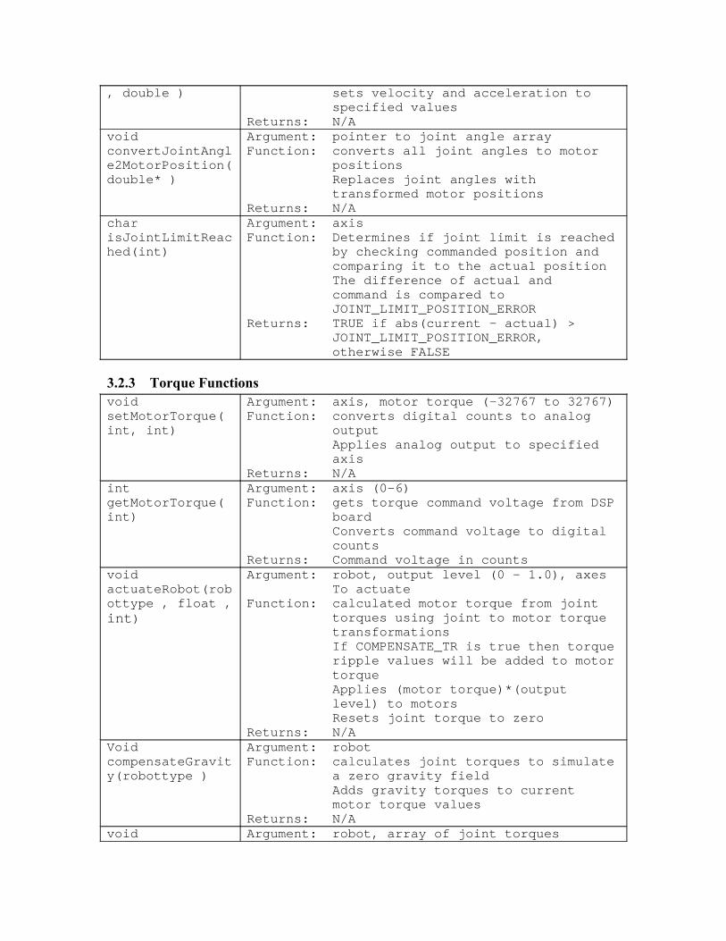
3.2.3 Torque Functionsvoid setMotorTorque( int, int)
Argument: axis, motor torque (-32767 to 32767)Function: converts digital counts to analog
outputApplies analog output to specified axis
Returns: N/Aint getMotorTorque( int)
Argument: axis (0–6)Function: gets torque command voltage from DSP
boardConverts command voltage to digital counts
Returns: Command voltage in countsvoid actuateRobot(robottype , float , int)
Argument: robot, output level (0 – 1.0), axes To actuate
Function: calculated motor torque from joint torques using joint to motor torque transformationsIf COMPENSATE_TR is true then torque ripple values will be added to motor torqueApplies (motor torque)*(output level) to motorsResets joint torque to zero
Returns: N/AVoid compensateGravity(robottype )
Argument: robotFunction: calculates joint torques to simulate
a zero gravity fieldAdds gravity torques to current motor torque values
Returns: N/Avoid Argument: robot, array of joint torques
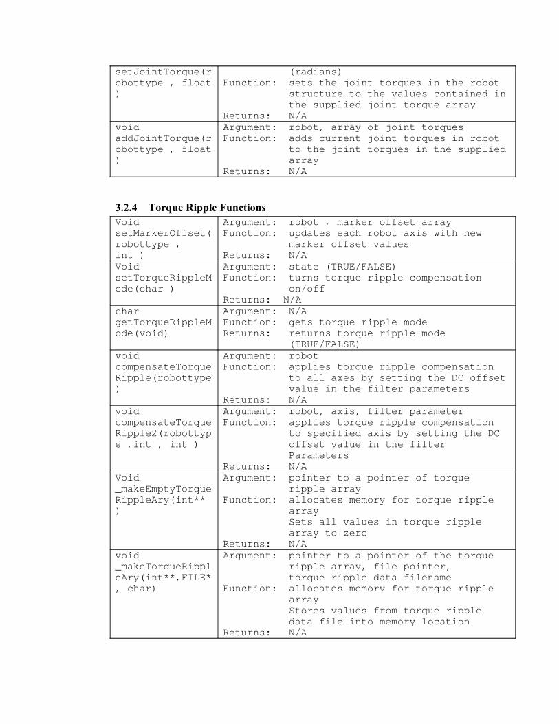
setJointTorque(robottype , float )
(radians)Function: sets the joint torques in the robot
structure to the values contained in the supplied joint torque array
Returns: N/Avoid addJointTorque(robottype , float )
Argument: robot, array of joint torquesFunction: adds current joint torques in robot
to the joint torques in the supplied array
Returns: N/A
3.2.4 Torque Ripple FunctionsVoid setMarkerOffset( robottype , int )
Argument: robot , marker offset arrayFunction: updates each robot axis with new
marker offset valuesReturns: N/A
Void setTorqueRippleMode(char )
Argument: state (TRUE/FALSE)Function: turns torque ripple compensation
on/offReturns: N/A
char getTorqueRippleMode(void)
Argument: N/AFunction: gets torque ripple modeReturns: returns torque ripple mode
(TRUE/FALSE)void compensateTorqueRipple(robottype )
Argument: robotFunction: applies torque ripple compensation
to all axes by setting the DC offset value in the filter parameters
Returns: N/Avoid compensateTorqueRipple2(robottype ,int , int )
Argument: robot, axis, filter parameterFunction: applies torque ripple compensation
to specified axis by setting the DC offset value in the filter Parameters
Returns: N/AVoid _makeEmptyTorqueRippleAry(int** )
Argument: pointer to a pointer of torque ripple array
Function: allocates memory for torque ripple arraySets all values in torque ripple array to zero
Returns: N/Avoid _makeTorqueRippleAry(int**,FILE*, char)
Argument: pointer to a pointer of the torque ripple array, file pointer, torque ripple data filename
Function: allocates memory for torque ripple arrayStores values from torque ripple data file into memory location
Returns: N/A

char MarkerFound(int )
Argument: axisFunction: moves the specified motor
continuously until the marker pulse is foundSets marker position to zero position
Returns: TRUE if successful, FALSE if failed to find marker pulse
char manMarkerFound(int)
Argument: axisFunction: asks user to move the specified
motor continuously until the marker pulse is foundSets marker position to zero position
Returns: TRUE if successful, FALSE if failed to find marker pulse
int MarkerFoundOffset(int)
Argument: axisFunction: moves the specified motor
continuously until the marker pulse is found
Returns: Marker offset valueint manMarkerFound(int)
Argument: axisFunction: asks user to move the specified
motor continuously until the marker pulse is found
Returns: Marker offset value
3.2.5 General Robot Functionsvoid displayRobot(robottype )
Argument: robotFunction: displays all elements for each axisReturns: N/A
void initRobot(void)
Argument: N/AFunction: initializes DSP
sets filter parametersChecks software against hardware codeSet software limitsIdles controllersSets dac output to zeroSets in position windowInitializes safety bit
NOTE: This function must be called before any other functions that use the DSPReturns: N/A
void deinitRobot(void)
Argument: N/AFunction: sets DAC output to zero
Idles motorsSets the KillBit low and shuts the cabinet down
Returns: N/Avoid killRobot(void)
Argument: N/AFunction: cuts power to robot using the

software emergency kill bitReturns: N/A
void enableRobot(int )
Argument: mode (Position or Torque)Function (position): runs controllers and
enables ampsFunction (torque): idles controllers and
enables amps NOTE: in torque mode controllers are idled to disable the PID control and then the amplifiers are enabledReturns: N/A
void disableRobot(void)
Argument: N/AFunction: idles controllers
disables amplifiersReturns: N/A
void makeRobot(robottype )
Argument: robotFunction: creates robot initialization
parameters for all axesRobot.mpos = 0Robot.ma = 0 (motor angle)robot.ja = 0 (joint angle)robot.s = 0 (sin of joint angle)robot.c = 0 (cos of joint angle)robot.jt = 0 (joint torque)robot.mt = 0 (motor torque)robot.mo = 0 (motor offset)creates torque ripple array from files if COMPENSATE_TR is TRUE
Returns: N/Achar isEmptyRobot(robottype )
Argument: robotFunction: determines if robot has been createdReturns: TRUE if it has been created, FALSE
It has notvoid destroyRobot(robottype )
Argument: robotFunction: frees up the memory that was used
for the torque ripple dataReturns: N/A
void updateRobot(robottype )
Argument: robotFunction: updates all parameters in the robot
structure:Motor angleJoint angleSin of joint angleCos of joint angleAbsolute motor position
Returns: N/A
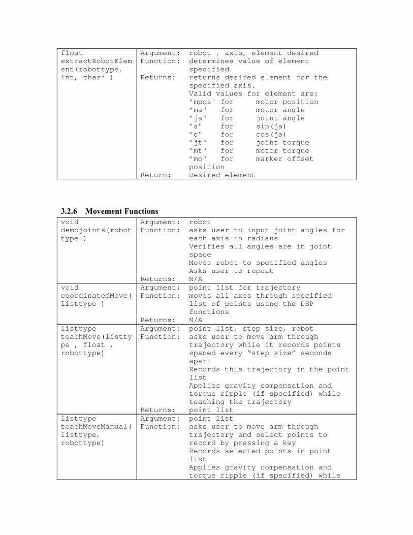
float extractRobotElement(robottype, int, char* )
Argument: robot , axis, element desiredFunction: determines value of element
specifiedReturns: returns desired element for the
specified axis.Valid values for element are:"mpos" for motor position"ma" for motor angle"ja" for joint angle"s" for sin(ja)"c" for cos(ja)"jt" for joint torque"mt" for motor torque"mo" for marker offset position
Return: Desired element
3.2.6 Movement Functionsvoid demojoints(robottype )
Argument: robotFunction: asks user to input joint angles for
each axis in radiansVerifies all angles are in joint spaceMoves robot to specified anglesAsks user to repeat
Returns: N/Avoid coordinatedMove(listtype )
Argument: point list for trajectoryFunction: moves all axes through specified
list of points using the DSP functions
Returns: N/Alisttype teachMove(listtype , float , robottype)
Argument: point list, step size, robotFunction: asks user to move arm through
trajectory while it records points spaced every “step size” seconds apartRecords this trajectory in the point listApplies gravity compensation and torque ripple (if specified) while teaching the trajectory
Returns: point listlisttype teachMoveManual(listtype, robottype)
Argument: point listFunction: asks user to move arm through
trajectory and select points to record by pressing a keyRecords selected points in point listApplies gravity compensation and torque ripple (if specified) while

teaching the trajectoryReturns: point list
3.2.7 Point_List Functionslisttype makePointListElement(double* )
Argument: array of motor positionsFunction: creates element for the point list
Assigns element value to motor position valueSets next element address to NULL
Returns: Element with next address set to NULL
char isEmptyPointList(listtype )
Argument: point listFunction: determines if point list is emptyReturns: TRUE if point list empty, FALSE if
contains valuesvoid destroyPointList(listtype )
Argument: point listFunction: frees memory previously allocated
for the point listReturns: N/A
listtype addPointListElement(listtype , double* )
Argument: point list, array of motor positionsFunction: calls makePointList to create next
element in the point listPoints previous element to address of current point
Returns: point listvoid printPointList(listtype )
Argument: point listFunction: prints point listReturns: N/A
double* extractPointListData(listtype , int )
Argument: point list, element to extractFunction: points list to element desiredReturns: pointer to element desired
3.2.8 File Functionschar loadTrajectoryFile(char* )
Argument: pointer to filenameFunction: loads trajectories from files
created with saveTrajectoryFile() or with a .trj extension
Returns: N/Achar saveTrajectoryFile(char* )
Argument: pointer to filenameFunction: saves trajectories to text file with
a .trj extensiondate header is added
NOTE: it is possible to edit the trajectory by editing this fileReturns: N/A

3.2.9 Awaken/Sleep Routines
void Sleep1(void)
Argument: N/AFunction: moves robot to predefined sleep
positionThis position is experimentally determined and can be changed by the user
Returns: N/Avoid Sleep2(void)
Argument: robotFunction: Applies gravity compensation at the
SLEEP_SCALE_FACTOR so arm will fall to least energy state slowly
Returns: N/AVoid Sleep4(void)
Argument: N/AFunction: cuts power to robot by calling
KillRobot()This program relies solely on dynamic braking as it’s damping factor
Returns: N/Avoid Awaken1(void)
Argument: N/AFunction: Asks user to move robot to zero
position Sets position to be zero locationAsks user to move to a safe rest positionSets rest position as current position
Returns: N/Avoid awakenRobot(robottype)
Argument: robotFunction: Automatically moves robot through
joint space to find zero positionStarts at the outermost joint and works backwards to the base axisMoves robot to zero position
NOTE: Robot must have outerlink resting against innerlink and J2 on its negative joint stopReturns: N/A
char StillMoving(float)
Argument: array of motor velocitiesFunction: determines if robot is still movingReturns: returns TRUE if robot is moving,
FALSE if stopped
3.3 Additional Program Summary
Barrett Technology, Inc. has supplied several programs that demonstrate uses of the functions in btech.lib.
3.3.1 Wamdemo.c Program
A demonstration program, wamdemo.c, was developed to show some of the BarrettArm, BarrettWrist and BarrettHand functionality. Wamdemo.c is

comprised of 15 different tests, which give the user examples of how to program the entire system properly. This program can be used to become familiar with the robot workspace, kinematics and joint transforms.
Test 1: Demonstrates how to move robot to an arbitrary position.• This test calls a manual awaken program to find the zero position. The manual
awaken program instructs the user to move the robot to it’s zero position and press a key. When the key is pressed the robot is zeroed.
• The user manually enables the current controllers. • The program enables the robot for position control.• CommandMoveJoint(n_axis_point) moves the robot to the joint positions
specified in n_axis_point• When the robot has moved to the desired position it then moves to the sleep
position by calling sleep1(). The sleep position has the outer link resting against the inner link, joint 2 resting on its negative joint stop and the rest of the joints in their zero position.
• Concludes by deinitializing robot and flushing robot parameters from memory.
Test 2: Demonstrates sleep routine that applies partial gravity compensation.• Calls an automatic awaken routine, awakenRobot(Robot), which finds the
zero position of the robot. The zero position is determined by using the locations of the joint stops. When the zero position is found it zeros the motors. NOTE: To use the awakenRobot() function the robot needs to have the outer link resting against the inner link and joint 2 needs to be resting on the negative joint stop. The other axes do not have constraints about their start position.
• Sleep2(Robot) is called which actuates the robot at a percentage of gravity compensation. The percent compensation is determined by the value of SLEEP_SCALE_FACTOR. The robot will fall to its least energy state slowly.
• Concludes by deinitializing robot and flushing robot parameters from memory.
Test 3: Demonstrates automatic awaken routine.• Calls an automatic awaken routine, awakenRobot(Robot), which finds the
zero position of the robot. The zero position is determined by using the locations of the joint stops. When the zero position is found it zeros the motors. NOTE: To use the awakenRobot() function the robot needs to have the outer link resting against the inner link and joint 2 needs to be resting on the negative joint stop. The other axes do not have constraints about their start position.
• Moves robot to sleep position by calling sleep1().• Concludes by deinitializing robot and flushing robot parameters from
memory.
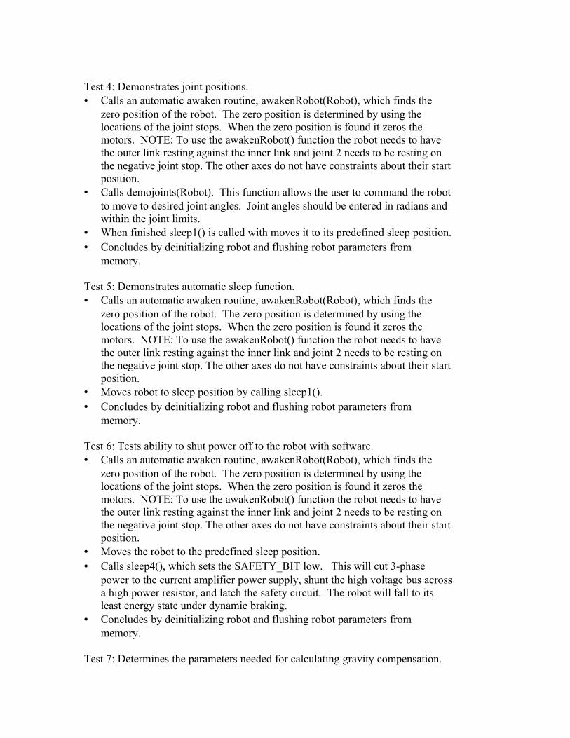
Test 4: Demonstrates joint positions.• Calls an automatic awaken routine, awakenRobot(Robot), which finds the
zero position of the robot. The zero position is determined by using the locations of the joint stops. When the zero position is found it zeros the motors. NOTE: To use the awakenRobot() function the robot needs to have the outer link resting against the inner link and joint 2 needs to be resting on the negative joint stop. The other axes do not have constraints about their start position.
• Calls demojoints(Robot). This function allows the user to command the robot to move to desired joint angles. Joint angles should be entered in radians and within the joint limits.
• When finished sleep1() is called with moves it to its predefined sleep position.• Concludes by deinitializing robot and flushing robot parameters from
memory.
Test 5: Demonstrates automatic sleep function.• Calls an automatic awaken routine, awakenRobot(Robot), which finds the
zero position of the robot. The zero position is determined by using the locations of the joint stops. When the zero position is found it zeros the motors. NOTE: To use the awakenRobot() function the robot needs to have the outer link resting against the inner link and joint 2 needs to be resting on the negative joint stop. The other axes do not have constraints about their start position.
• Moves robot to sleep position by calling sleep1().• Concludes by deinitializing robot and flushing robot parameters from
memory.
Test 6: Tests ability to shut power off to the robot with software.• Calls an automatic awaken routine, awakenRobot(Robot), which finds the
zero position of the robot. The zero position is determined by using the locations of the joint stops. When the zero position is found it zeros the motors. NOTE: To use the awakenRobot() function the robot needs to have the outer link resting against the inner link and joint 2 needs to be resting on the negative joint stop. The other axes do not have constraints about their start position.
• Moves the robot to the predefined sleep position.• Calls sleep4(), which sets the SAFETY_BIT low. This will cut 3-phase
power to the current amplifier power supply, shunt the high voltage bus across a high power resistor, and latch the safety circuit. The robot will fall to its least energy state under dynamic braking.
• Concludes by deinitializing robot and flushing robot parameters from memory.
Test 7: Determines the parameters needed for calculating gravity compensation.
• Calls an automatic awaken routine, awakenRobot(Robot), which finds the zero position of the robot. The zero position is determined by using the locations of the joint stops. When the zero position is found it zeros the motors. NOTE: To use the awakenRobot() function the robot needs to have the outer link resting against the inner link and joint 2 needs to be resting on the negative joint stop. The other axes do not have constraints about their start position.
• Moves robot to calibration positions and determines gravity compensation vector. See section 5 for information on how gravity compensation works.
• Concludes by deinitializing robot and flushing robot parameters from memory.
Test 8: Applies torque ripple compensation to all axes.• Sets COMPENSATE_TR to TRUE by calling setTorqueRippleMode().
When this parameter is set, torque ripple will be compensated for when actuateRobot() is called.
• MakeRobot() is called after setting COMPENSATE_TR to TRUE. If COMPENSATE_TR is set then the torque ripple data files are loaded into memory for future use.
• ManMarkerFoundOffset(axis) is called to find the encoder marker pulse on each of the axes. The user will be required to move the joints to find the marker pulses.
• SetMarkerOffset() will take the array of marker offsets for the motors and set the value in the robot structure. The robot is now ready for torque ripple compensation.
• The robot is enabled for torque commands by calling enableRobot(TORQUE). This will enable the amplifiers and idle the PID control for each axis.
• The user is given the option to feel the difference between moving the robot with and without torque ripple compensation. Changing the value of COMPENSATE_TR does this.
• Concludes by deinitializing robot and flushing robot parameters from memory.
Test 9: Tests the repeatability of the awakenRobot() function.• This program calls zeroAxisRepeatability(). This function finds the zero
position of each of the axes SAMPLES times. The average encoder position and the maximum deviation are found and displayed.
• Moves robot to sleep position by calling sleep1().• Concludes by deinitializing robot and flushing robot parameters from
memory.
Test 10: Test gravity compensation with and without torque ripple compensation• Calls an automatic awaken routine, awakenRobot(Robot), which finds the
zero position of the robot. The zero position is determined by using the locations of the joint stops. When the zero position is found it zeros the

motors. NOTE: To use the awakenRobot() function the robot needs to have the outer link resting against the inner link and joint 2 needs to be resting on the negative joint stop. The other axes do not have constraints about their start position.
• If COMPENSATE_TR is set then the torque ripple data is loaded and each marker pulse is found for the arm.
• Moves robot to sleep position by calling sleep1().• If the wrist is on the robot, it will call controller_run(axis) for each of the wrist
motors so they will hold position while the arm is being compensated for gravity.
• When ‘c’ is pressed the arm will have torque ripple compensation• When ‘n’ is pressed the arm will have no torque ripple compensation.• Concludes by deinitializing robot and flushing robot parameters from
memory.
Test 11: Teach and Play• SetTorqueRippleMode() turns torque ripple on or off depending on the
variable• MakePointList() is called and creates a pointer to point_list.• Calls an automatic awaken routine, awakenRobot(Robot), which finds the
zero position of the robot. The zero position is determined by using the locations of the joint stops. When the zero position is found it zeros the motors. NOTE: To use the awakenRobot() function the robot needs to have the outer link resting against the inner link and joint 2 needs to be resting on the negative joint stop. The other axes do not have constraints about their start position.
• If COMPENSATE_TR is set then the marker pulses are found.• Move robot to sleep position by calling sleep1().• Allows user to load prerecorded trajectory if desired. • Allows user to record points manually (1) or automatically (2).
1) Puts arm into gravity compensation mode. Asks user to move robot around and press any key to record a trajectory point. When last point is taken, the user is asked to press the space bar, which will command the robot to hold position.
2) Puts arm into gravity compensation mode. Asks user to press ‘r’ to start recording points. Every STEP seconds a point will be recorded for that trajectory. The user is instructed to press the space bar to stop recording points. After the last point is recorded the robot is commanded to hold position.
• The program will prompt the user for number of playback cycles to run.• The program will playback the number of trajectory cycles specified by the
user.

• The program will ask the user if they want to cycle the same trajectory again. If the user presses the space bar (selects “yes”) then it will ask for number of cycles and the replay the trajectory.
• If the user selects “no”, the robot moves to the sleep position by calling sleep1().
• The user is now given the option to save the trajectory. If desired, saveTrajectoryFile() is called which will save the trajectory to a file.
• The user is given the option to record a new trajectory. If desired the program jumps back to the point where it asks for a prerecorded trajectory.
• Otherwise the robot is deinitialized and the point_list is flushed from memory.
• Concludes by deinitializing robot and flushing robot parameters from memory.
Test 12: Demonstrates use of BarrettArm, Wrist and Hand from within the same program.• Before calling this function, run the BarrettHand communication program
Async.com.• Calls an automatic awaken routine, awakenRobot(Robot), which finds the
zero position of the robot. The zero position is determined by using the locations of the joint stops. When the zero position is found it zeros the motors. NOTE: To use the awakenRobot() function the robot needs to have the outer link resting against the inner link and joint 2 needs to be resting on the negative joint stop. The other axes do not have constraints about their start position.
• Moves robot to predefined position.• Issues several basic BarrettHand commands.• Moves robot to sleep position by calling sleep1().• Concludes by deinitializing robot and flushing robot parameters from
memory.
Test 13: Tests gravity compensation with ability hold to position.• Calls an automatic awaken routine, awakenRobot(Robot), which finds the
zero position of the robot. The zero position is determined by using the locations of the joint stops. When the zero position is found it zeros the motors. NOTE: To use the awakenRobot() function the robot needs to have the outer link resting against the inner link and joint 2 needs to be resting on the negative joint stop. The other axes do not have constraints about their start position.
• If COMPENSATE_TR is set then the marker pulses are found.• Moves robot to sleep position by calling sleep1().• Enables robot for torque control• If ‘c’ is pressed then the robot will be in gravity compensation mode.• If ‘h’ is pressed then the robot will hold position.

• Moves robot to sleep position by calling sleep1().• Concludes by deinitializing robot and flushing robot parameters from
memory.
Test 14: Idles motors.• Deinitializes robot and flushes robot parameters from memory.
Test 15: Converts binary torque ripple files to readable text files.• Prompts for motor axis.• Prompts for smooth or raw data.• Creates and prints source and destination files.• Converts specified motor axis torque ripple from binary to text format.• Closes all files
3.3.2 Trdaq.c Program
This program determines the torque ripple fingerprint of each motor and needs to be called with the target motor axis as an argument.
Example: trdaq 0 (to gather torque ripple data for axis 0)
The torque ripple data is determined by first finding the marker pulse, calling the function markerFound(). Now the index position is considered position zero. The motor is commanded to move through one full revolution in the positive direction. As the motor moves through one revolution, the computer reads and stores positions and command values. When the motor is finished one revolution in the positive direction it reverses for one full revolution. Again, the computer reads and stores positions and command values. While taking the raw data the values are displayed on a discrete value versus encoder position graph.
Once all of the values have been taken, all of the zero values in the arrays are filled with the nearest nonzero value. This data is saved into raw_tr.d<axis>. The average of the forward and reverse data is saved in avrg_tr.d<axis>. Smooth data is derived from applying a non-weighted 11-point averaging filter to the Average Data and stored into smth_tr.d<axis>. When all of the data has been taken and files have been created, the user is given the opportunity to test the smooth or raw data.
For more information on torque ripple compensation see section 4.
3.3.3 Trtest.c Program
This program allows the user to test a specific type of torque ripple data on each motor and needs to be called with the target motor axis as an argument.
Example: trtest 0 (to apply torque ripple compensation to motor axis 0)

The user is asked to specify what kind of torque ripple data to apply: smooth, raw or average. The respective files are smth_tr.d<axis>, raw_tr.d<axis> and avrg_tr.d<axis>. Because torque ripple is based on the position of the rotor with respect to the stator the marker pulse needs to be found. Calling markerFound() does this. When the robot is enabled the axis specified will have torque ripple compensation.
For more information on torque ripple compensation see section 4.
4. Torque Ripple Compensation
All electric motors possess some amount of torque ripple. Torque ripple is the resulting varying force on the rotor from the interaction of the motor magnets with the coils and iron cores in the stator. In many applications involving low-bandwidth and/or high friction mechanical systems, ripple is unnoticeable at the output. However, the high-bandwidth of the BA4-310 and BW3-210 transmits such ripple. Thus, some form of torque ripple compensation is desirable.
4.1 Algorithm
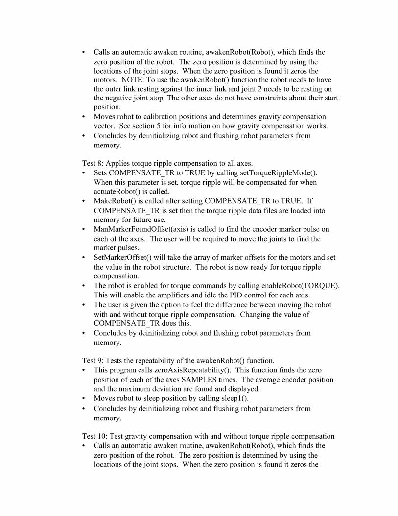
By measuring and recording the steady state torque required to hold the unloaded and uncabled motor spindle at each of its 4096 discretely measurable positions, one creates a basis for torque ripple compensation. The executable
<drive>:\btech\source\tr\trdaq.exe
locates the zero position of the motors by monitoring the index/marker pulse, which is wired into the digital input channel. The program then collects torque ripple data in both the positive and negative motor directions. The ripple data for each direction of travel is averaged and then filtered using an unweighted, 11-point averaging filter. Trdaq.c records the raw ripple data in binary format to the file raw_rip.d<axis number>. The smoothed data is recorded in binary format to smth_rip.d<axis number>. A typical example of smooth data can be found in Figure 2.
Smth Torque Ripple
-1
-0.5
0
0.5
1
1.5
2
2.5
1
303
605
907
1209
1511
1813
2115
2417
2719
3021
3323
3625
3927
Position
% o
f M
ax T
orq
ue
Smth TR
Figure 2: Typical smooth torque ripple data

4.2 Compensation
Torque ripple can be compensated using two different methods. First, using a combination of the get_filter() and set_filter() commands, the recorded torque ripple data can be superimposed on top of any motion control torque calculations performed by the DSP. By setting the DF_OFFSET variable equal to the torque ripple data for the present motor position, torque ripple can be effectively cancelled. The following code fragment performs this task
get_filter(axis,&fp);fp[DF_OFFSET]=ripple_torque;set_filter(axis,fp);
It is also possible to directly specify torques to be applied to individual axes. The most explicit manner in which to perform this action is to specify a torque to be applied to the DAC for a particular axis:
set_dac_output(axis, ripple_torque);
Note that if this method is used in conjunction with PID motion control, the commanded torque overrides the torque calculated for PID motion control.
4.3 Torque Scaling
The current controllers are configured in torque control mode. In this sense, torque control mode is analogous to current control:
iKT *=τ Equation 1
A full-scale integer count output of 32767 corresponds to a full-scale voltage output on the PC-DSP board of 10 V. Full-scale current output on the current controllers is 6 Arms. Thus, a constant of proportionality can be obtained relating static output torque to integer counts, c:
cK
cV
Arms
counts
VK
TC
T
*
*10
6*
32767
10*
=
=
τ
τEquation 2
The following is a table of the motor torque constants, KT, for each motor, full scale current, ifs, and their associated KTC:
Table 2 - Torque Conversion Parameters
KT [Nm/A] i_fs [A] KTC [Nm/count]Axes 0-3 0.456 6 8.35E-5Axes 4-5 0.106 6 1.94E-5
Axis 6 0.0458 6 8.39E-6
Barrett Technology sets a maximum torque limit on the Kollmorgen Controllers of 2.52 A.

4.4 Considerations
Note that although the effectiveness of this compensation is dependent on the quality of torque ripple data, when many axes are being compensated, the compensation is strongly dependent on control program cycle frequency and motor speed. A busy control program executing fast robot motions may potentially have difficulty achieving adequate torque ripple compensation.
The torque ripple map used for compensation is derived from a motor moving at a steady slow velocity. The torque ripple has not been mapped with high velocity or torque and therefore Barrett cannot guarantee our method of torque ripple compensation under those conditions.

5. Gravity Compensation
5.1 Theory
As one of the transparent behaviors of Computer-assisted Teach and Play, gravity compensation makes the robot feel weightless. This makes programming an effortless act of simply guiding the robot through a desired trajectory. Gravity compensation involves calculating the necessary joint torques required to balance the arm statically against gravitational loading and overlaying those torques through precise force control. For the purpose of verifying the technique, the four axes of the Barrett BA4-310 manipulator’s regional structure were gravity-compensated. The necessary equations were derived by applying Lagrange’s equation to an articulated robot manipulator found in Asada-86. Lagrange’s equation has the form
QLL
dt
d
=−
θ∂
∂θ∂
∂ Equation 3
where
L = T − U Equation 4
T and U are the kinetic and potential energy, respectively, of the entire system, θ is a 4 ×1 vector consisting of the joint velocities of the Barrett arm,
v θ is a
4 ×1 vector consisting of the joint positions, and v Q is a vector of generalized
forces acting on the robot.
Expanding Lagrange’s equation yields
QUTU
dt
dT
dt
d
=+−
−
θ∂
∂θ∂
∂θ∂
∂θ∂
∂ Equation 5
For static conditions, 0=θ and T=0, the only generalized forces acting on the
arm are the joint torques. Applying this to Lagrange’s equation results in the equation describing the equilibrium state of the manipulator:
j
U τθ∂
∂ =
Equation 6

where v τ j is the joint torque. Therefore, in order to solve for the torque needed to
support the manipulator in static equilibrium, the potential energy of the system must be found.
The potential energy of the manipulator is derived by modeling the manipulator and end tip mass as three point masses connected by rigid, massless rods. Two of these point masses are located at the center of mass of each link, and the third is the object mass located at the end tip.
To find the potential energy, the center of masses must first be described in their respective frames and then written relative to the fixed frame {0} by using forward kinematic transformations. Figure 3 shows the arm in its “home” configuration with Cartesian coordinate frames attached according to the Denavit-Hartenberg notation described in Craig-89. This notation differs slightly from the classical Denavit-Hartenberg notation described by other authors such as Asada-86 and Paul-81. The location of the X and Z axes of the coordinate frames {0}, {1}, {2}, {3}, {4}, and {w} are shown. The Y axis of each coordinate frame can be found by using the right hand rule. Frame {0} is located in the base of the robot and is stationary, while frame {w} is located at the end tip.

Z w
Xw
L3
L4
d3
d3
Z 0 Z 1,
X0 , X1 , X 2
Z 2
θ 2
θ 1
θ 4
θ 3
X4
Z 4
Z 3
X3
pc4
4m
pc 3
3m
lm
Figure 3: BarrettArm in “home” position with the Denavit-Hartenberg frames and parameters shown.

Referring to , the position of link 3’s center mass written with respect to frame {3} is:
3pc 3 =p3x
0
p3z
Equation 7
The position of the center of mass of link 4 written with respect to frame {4} is:
4 pc4 =p4x
p4y
0
Equation 8
The position of the end tip mass written with respect to the wrist frame {w} is
w pl =0
0
0
Equation 9
The potential energy of the manipulator is determined by adding the potential energy of each link. Applying the general equation for potential energy from Asada-86 to the BA4-310 arm yields:
{ } { } +
+
=1
)(0001
)(000 44
34
23
12
014
33
23
12
013
cc pTTTTgm
pTTTgmU
{ }
1)(000 43
42
31
20
1l
w
wl
pTTTTTgm
Equation 10
Where g is the acceleration of gravity and Tii −1
is the 4 × 4 homogeneous kinematic transformation, which defines frame {i} relative to frame {i-1}. Note that the multiplication of each link center of mass by the kinematic transformations describes the center of masses in the fixed frame {0}. The position vectors of each center of mass include a “1” since the equations use 4 × 4 homogeneous transformations.
The potential energy terms are multiplied and the partial derivatives with respect to each joint angle are taken according to Lagrange’s equation. The resulting equations for each joint torque are given below in matrix form where jiτ signifies the torque required at joint i and “c” and “s” are abbreviations for the cosine and sine functions respectively.

+++++
−−
+−−
−−+−=
)(
)(
)(
)(
00
0
0000
3333433
33433
444
344
2434242423
32432324
2324322443242
4
3
2
1
LmpmLmLmg
dmdmpmg
Lmpmg
dmpmg
sccscccssc
sssssssc
sccsccsccccss
lz
lx
ly
lx
j
j
j
j
ττττ
Equation 11
These equations describe the joint torques necessary to suspend the BA4-310 link structure and end tip mass against gravitational loading. Note that since the gravity vector is parallel with the first joint axis, the torque on the first joint remains zero for all configurations
v θ . Note also that all of the elements of the
right-hand-side mass-parameter vector are constants. In practice, these mass parameters are acquired through calculation from center-of-mass measurements or, more simply, by direct experimental measurement as described in the following section.
By pre-multiplying the joint torques given above by the joint-to-motor-torque transformation, these equations derived above give a complete solution of the motor torques necessary to support the links and end-tip object against gravity loading. Similar equations can be derived for the full seven-degree-of-freedom BarrettArm and Wrist. This requires three more kinematic transformations, resulting in equations of higher order but the same form.
5.2 Experimentally Determined Mass Parameters
The individual terms in the mass parameter vector are determined experimentally by carefully selecting certain configurations of the kinematic chain such that matrix in Equation 11 simplifies algebraically. Thus, by measuring the joint torques necessary to counter the effect of gravitational loading in such configurations, it is possible to generate a more simplified system of equations whose solution generates the desired mass parameters. A set of such configurations can be shown to exist for any serial manipulator with joint angles that are parallel or perpendicular to each other along the kinematic chain [Mayeda-84]. The method proposed herein is similar to that presented in Mayeda-84.
Figure 4 demonstrates the set of configurations used, where angles were chosen to be 0, 90, or -90 degrees according to the assignment of positive joint angles presented in Figure 3. Note that since axis 1 is parallel to the gravity vector, its position is arbitrary. For the notation of joint torques in Figure 4, the first of the two numbers corresponds to the joint number as in Figure 1, and the second number indicates the configuration number. Thus, τ j 41, is the measured joint torque at axis 4 in configuration number 1.

Let the elements of the mass parameter vector be labeled [ ]DCBA ,,, . Then, multiplying out the fourth row of matrix in Equation 11 yields:
BscccsAccscsj )()( 424324243241 ++−=τ Equation 12
In configuration 1, this simplifies to:
Bj −=41τ Equation 13

-9 0 2 3 4A x is
A n g le 0 0
C o n f ig u r a t io n 1
-9 0 9 02 3 4A x is
A n g le 0
C o n f ig u r a t io n 2
- 9 0-9 0 9 02 3 4A x is
A n g le
C o n f ig u ra t io n 3
- 9 0 °
τ j4 1τ j2 1
9 0 °- 9 0 °
τj4 2 τj2 2
τ j33 -90°
Figure 4: Configurations used to experimentally determine the mass parameters for gravity compensation.

Similarly, the other rows of matrix in Equation 11 are multiplied out. From configuration 1,
DBj +−=21τ Equation 14
From configuration 2,
Aj −=42τ Equation 15
From configuration 3,
CBj +−=33τ Equation 16
Rearranging and solving for unknowns:
41jB τ−= Equation 17
4121 jjD ττ −= Equation 18
42jA τ−= Equation 19
4133 jjC ττ −= Equation 20
Note that these are not the only configurations that can be used to determine the mass parameters.
The significance of using this method to determine mass parameters is that it can be done quickly and in an automated fashion with most robot kinematic structures. As such, if the robot is required to carry a different payload, the mass parameters of the robot system can be quickly recalibrated.


![Table of Contents List of Figures2 Chapter 2jklinger/thesis.pdfmodern nonlinear optics: the photorefractive effect [2]. For the work 4 presented in this thesis, a photorefractive crystal](https://img.pdfslide.us/doc/110x75/5f085f3a7e708231d421aed3/table-of-contents-list-of-figures2-chapter-2-jklingerthesispdf-modern-nonlinear.jpg)