Embed Size (px)
Citation preview

Table of Contents
Linear Actuator Base Arm/Elbow Joint Future Plan
Previous Issues:
• Rack and gear meshing slop
• Uniform linear movement through bearings
• Drive motor needs replacement
Improvement Ideas:
• Mount second gear to face of primary gear
• Replace linear roller bearings with sleeve bushings
• Replace motor with higher torque version
Linear Actuator
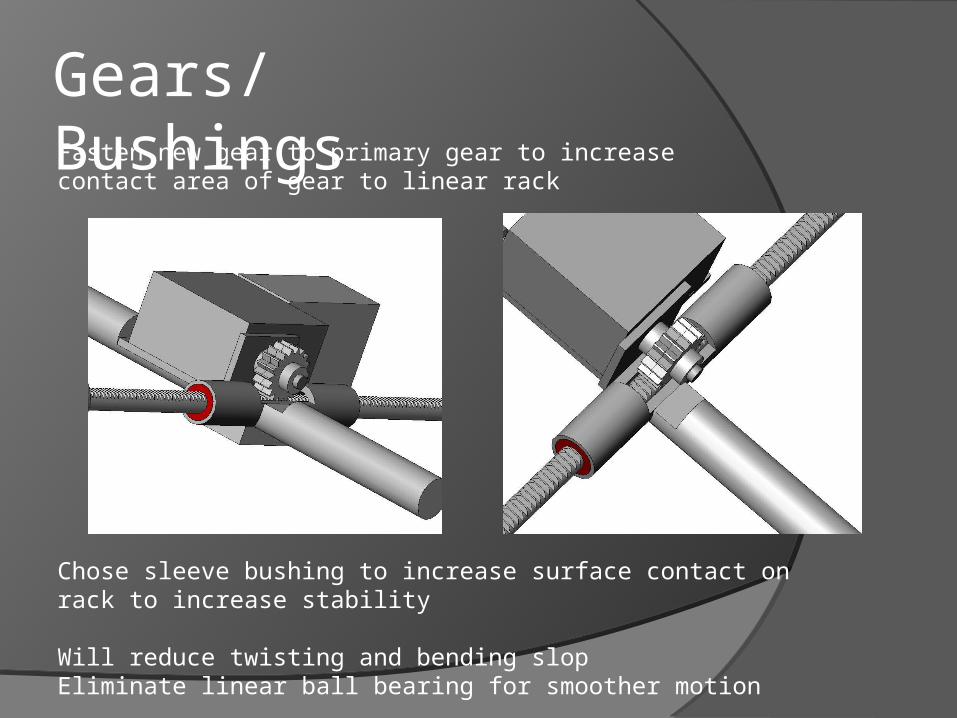
Gears/ BushingsFasten new gear to primary gear to increase contact area of gear to linear rack
Chose sleeve bushing to increase surface contact on rack to increase stability
Will reduce twisting and bending slopEliminate linear ball bearing for smoother motion
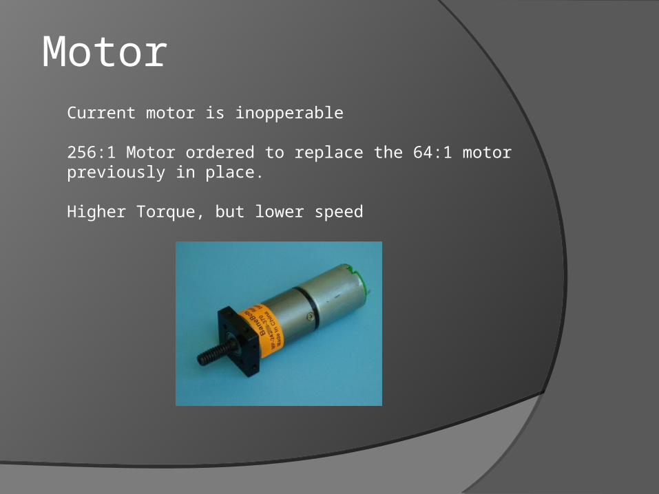
MotorCurrent motor is inopperable
256:1 Motor ordered to replace the 64:1 motor previously in place.
Higher Torque, but lower speed
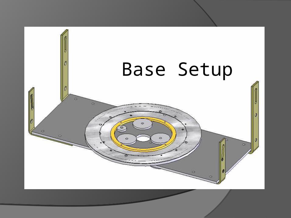
Base Setup
POT
Drive Gear
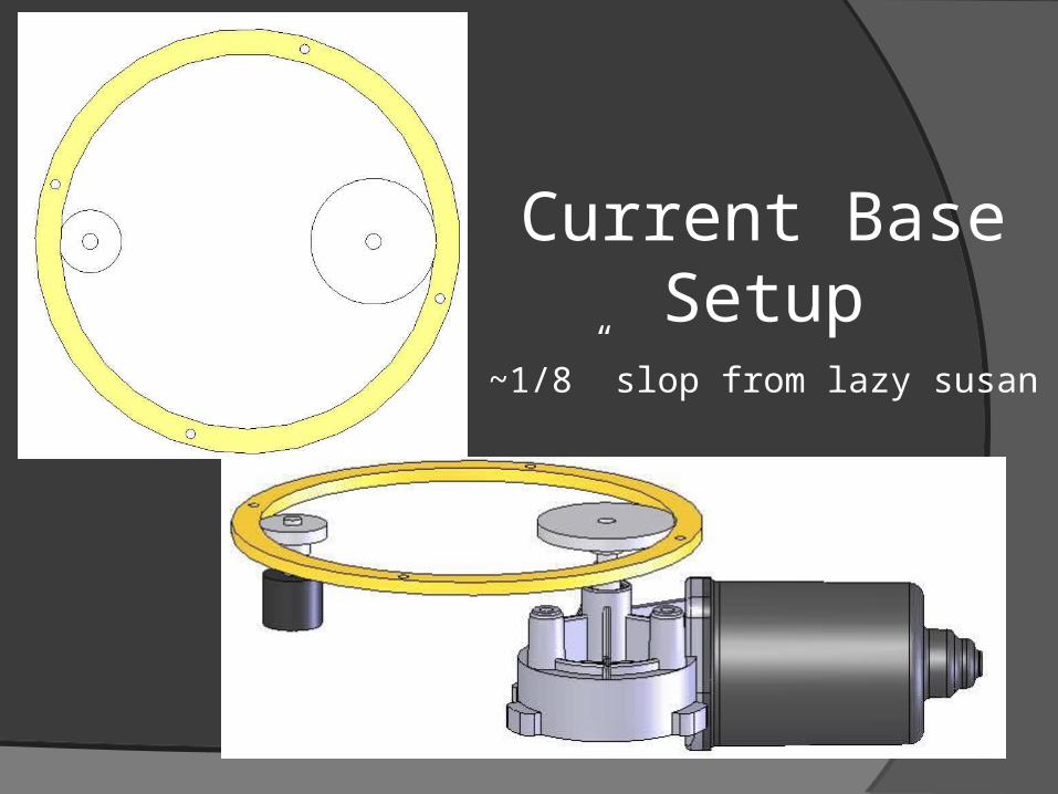
Current Base Setup
~1/8” slop from lazy susan
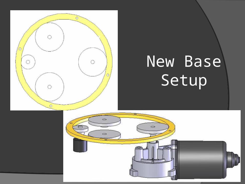
Drive Gear
New Base Setup
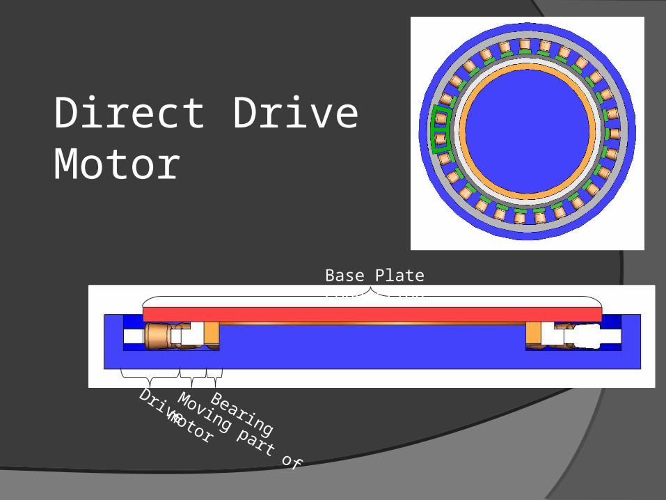
Direct Drive Motor
Base Plate Connection
DriveBearing
Moving part of
motor
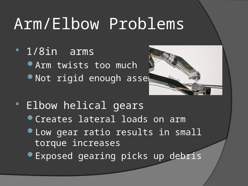
Arm/Elbow Problems
1/8in armsArm twists too muchNot rigid enough assembly
Elbow helical gearsCreates lateral loads on armLow gear ratio results in small torque
increasesExposed gearing picks up debris
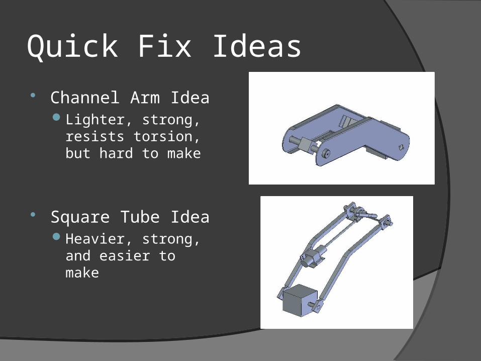
Quick Fix Ideas Channel Arm Idea
Lighter, strong, resists torsion, but hard to make
Square Tube IdeaHeavier, strong, and
easier to make
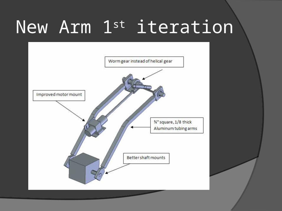
New Arm 1st iteration
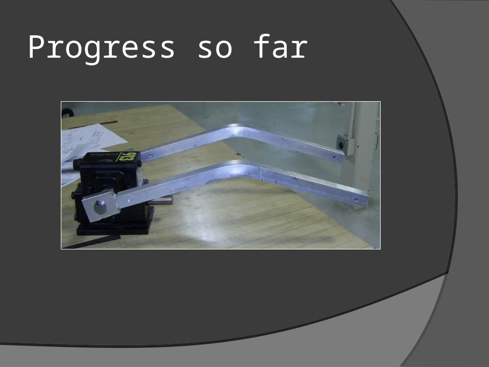
Progress so far
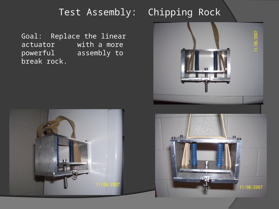
Test Assembly: Chipping Rock
Goal: Replace the linear actuator with a more powerful assembly to break rock.

Future Milestones
1st Iteration redesign – Nov. 28thth
Interim Report Fall Semester – Dec. 9th
Final Design Decision – Dec. 2008
Senior Design Expo – May 2008