Embed Size (px)
Citation preview

1
TABLE OF CONTENTS
SECTION: PAGE # 1. IRONMAN and JUNIOR Machine Specifications…………………………………….. Pg. 1
2. Machine Safety and General Maintenance.…………………….……………………… Pg. 2
3. Machine Mounting…….……………………………………………………………….. Pg. 2
4. 5” Gutter Machine Orientation………………………………………………………… Pg. 3
4D. IRONMAN 5” Gutter Machine Drawing……………………………………………… Pg. 4
4A. 6” Gutter Machine Orientation………………………………………………………… Pg. 5
4AD. IRONMAN 6” Gutter Machine Drawing……………………………………………… Pg. 6
5. Machine Electrical Controls, Operator Panels, and Basic Feeding Operation. ………. Pg. 7
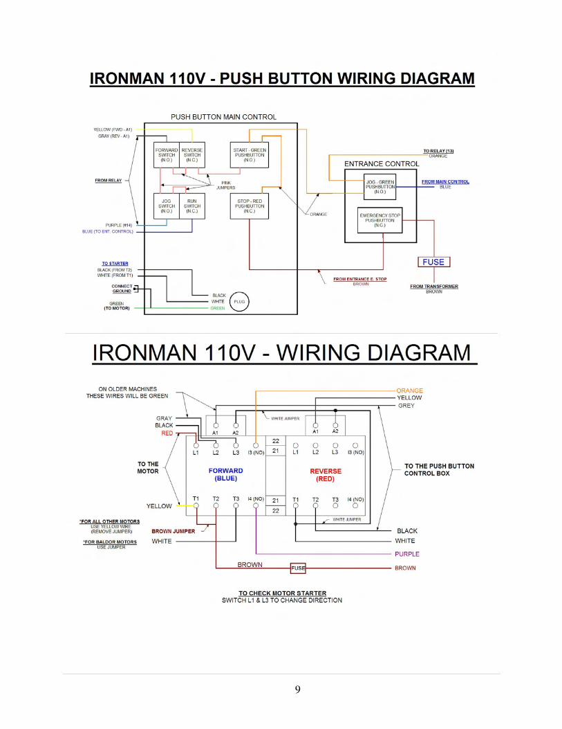
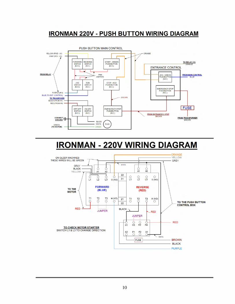
5D. Machine Wiring Diagrams..…………………………………………………………… Pg. 7-9
6. Machine Electrical Cord Requirements………….…….………………………………. Pg. 7
7. Upright Turnstile Assembly.……………..……………………………………………. Pg. 10
8. Spool Assembly and Loading Coil…………………………………………………….. Pg. 10
8D. Spool and Upright Drawing…….……………………………………………………... Pg. 11
9. Machine Entrance Guide System……….……………………………………………... Pg. 12
9D. Machine Entrance Guide Assembly Drawing……………………………………..…… Pg. 13
10. Machine Polyurethane Drive System….………………………………………………. Pg. 14
10D. Machine Polyurethane Drive System Drawing………………………………………… Pg. 14
11. Machine Forming Components and Assemblies………………………………………. Pg. 15
12. Machine Lip Forming Box……………..………………………………………………. Pg. 16-19
12D. Machine Lip Forming Box Drawings………………………………………………….. Pg. 16-19
13. Machine Exit End Forming and Drive Assembly……………………………………… Pg. 19-21
13D. Machine Top Exit Drive Adjustment and Assembly Drawings ……………………… Pg. 19-21
14. Machine Bead Roller Assembly………………………………………………………. Pg. 22
14D. Machine Bead Roller Drawing………………………………………………………... Pg. 22
15. Guillotine and Face Plate Assembly…………………………………………………... Pg. 23
15D. Guillotine and Face Plate Drawing……………………………………………………. Pg. 24
16. Basic Machine Setup Dimensions……………………………………………………… Pg. 25
16D. Basic Machine Setup Drawing………………………………………………………… Pg. 26
17. Gutter Talk…………………………………………………………………………….. Pg. 27
18. Machine Operation Recap and Summary……………………………………………… Pg. 28
19. Analyzing Gutter……………………………………………….……………………… Pg. 28
20. Trouble Shooting……………………………………………….……………………… Pg. 29-31
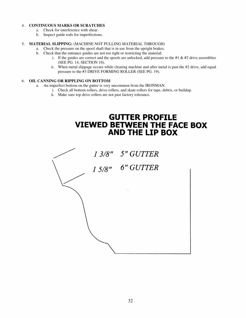
21. Drawing of Gutter Profile……………………………………………………………... Pg. 31
22.
22A.
22B.
Combo Machine Conversion 5” to 6”…………………………….. ……………………
Combo Machine Drawing. …………………………………………………………….
Combo Machine Conversion Drawings………………..……………………………….
Pg. 32-33
Pg. 34-35
Pg. 36-37
22. Combo Machine Conversion 6” to 5”……………………….….. ……………………. Pg. 38-39
23. Conversion Check List 5” to 6”……………………………………………………….. Pg. 40
24. Conversion Check List 6” to 5”……………………………………………………….. Pg. 41
25.
26.
Drawing of Gutter Profile……………………………………………………………...
Warranty Information……………………………………………………………………
Pg. 42
Pg. 43
2
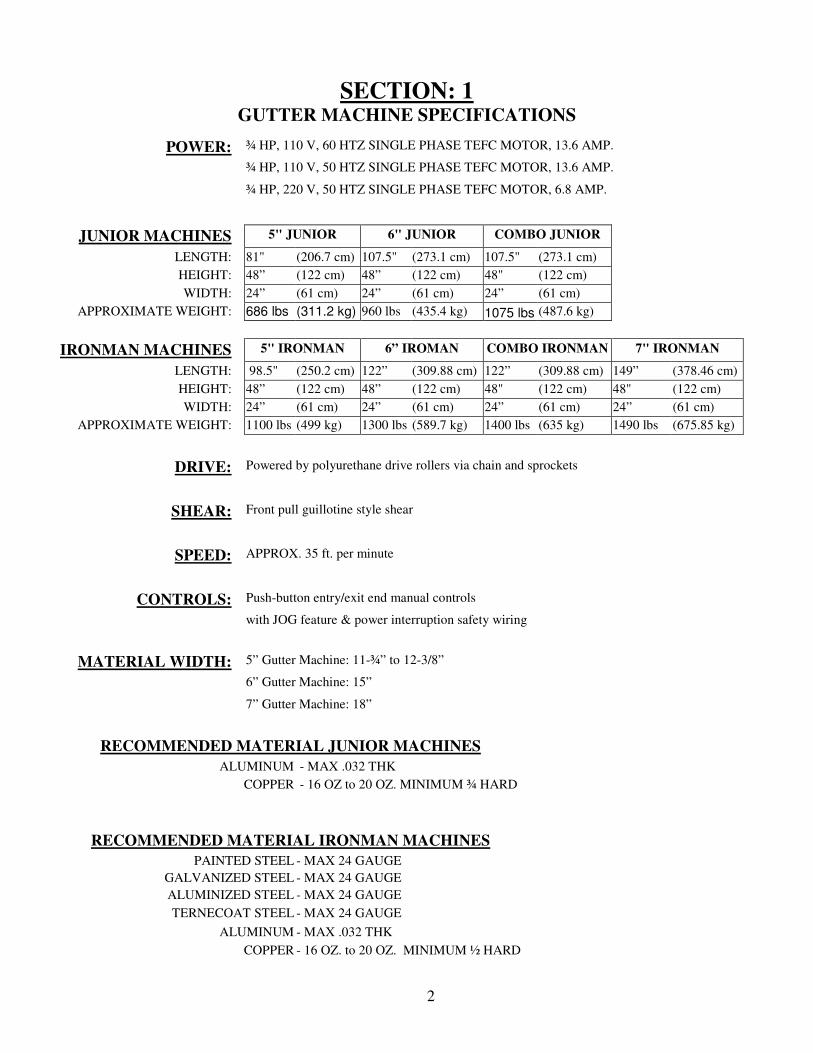
SECTION: 1 GUTTER MACHINE SPECIFICATIONS
POWER: ¾ HP, 110 V, 60 HTZ SINGLE PHASE TEFC MOTOR, 13.6 AMP.
¾ HP, 110 V, 50 HTZ SINGLE PHASE TEFC MOTOR, 13.6 AMP.
¾ HP, 220 V, 50 HTZ SINGLE PHASE TEFC MOTOR, 6.8 AMP.
JUNIOR MACHINES 5" JUNIOR 6" JUNIOR COMBO JUNIOR
LENGTH: 81" (206.7 cm) 107.5" (273.1 cm) 107.5" (273.1 cm)
HEIGHT: 48” (122 cm) 48” (122 cm) 48" (122 cm)
WIDTH: 24” (61 cm) 24” (61 cm) 24” (61 cm)
APPROXIMATE WEIGHT: 686 lbs (311.2 kg) 960 lbs (435.4 kg) 1075 lbs (487.6 kg)
IRONMAN MACHINES 5" IRONMAN 6” IROMAN COMBO IRONMAN 7" IRONMAN
LENGTH: 98.5" (250.2 cm) 122” (309.88 cm) 122” (309.88 cm) 149” (378.46 cm)
HEIGHT: 48” (122 cm) 48” (122 cm) 48" (122 cm) 48" (122 cm)
WIDTH: 24” (61 cm) 24” (61 cm) 24” (61 cm) 24” (61 cm)
APPROXIMATE WEIGHT: 1100 lbs (499 kg) 1300 lbs (589.7 kg) 1400 lbs (635 kg) 1490 lbs (675.85 kg)
DRIVE: Powered by polyurethane drive rollers via chain and sprockets
SHEAR: Front pull guillotine style shear
SPEED: APPROX. 35 ft. per minute
CONTROLS: Push-button entry/exit end manual controls
with JOG feature & power interruption safety wiring
MATERIAL WIDTH: 5” Gutter Machine: 11-¾” to 12-3/8”
6” Gutter Machine: 15”
7” Gutter Machine: 18”
RECOMMENDED MATERIAL JUNIOR MACHINES
ALUMINUM - MAX .032 THK
COPPER - 16 OZ to 20 OZ. MINIMUM ¾ HARD
RECOMMENDED MATERIAL IRONMAN MACHINES
PAINTED STEEL - MAX 24 GAUGE
GALVANIZED STEEL - MAX 24 GAUGE
ALUMINIZED STEEL - MAX 24 GAUGE
TERNECOAT STEEL - MAX 24 GAUGE
ALUMINUM - MAX .032 THK
COPPER - 16 OZ. to 20 OZ. MINIMUM ½ HARD
3
SECTION: 2 SAFETY AND GENERAL MAINTENANCE
• Read the entire manual prior to operation of this machine.
• Always keep covers and lids on machine during transportation, operation and storage. The covers are for the
operator’s safety. Not only will the covers protect the operator against injury, but they will also protect the
machine from outside elements.
• Do not transport or store machine with gutter coil in it. The forming rollers have adequate spacing, which will
not allow them to come in contact with one another. The polyurethane drive rollers do not need to be protected
from each other.
• Read all warning labels on machine.
• Disconnect the machine from power source prior to cleaning or performing any maintenance.
• Perform a daily inspection for debris, loose nuts, and/or bolts. With a clean machine, you can expect longer
machine life along with a better-finished product.
• Lubricate guillotine and chains weekly using waterproof synthetic grease.
• OUTSIDE STORAGE: If machine must be stored outside, tarp machine loosely in order to provide sufficient
ventilation to prevent condensation.
• Gear-Box oil level should be inspected annually. The gear oil level should be even with the bottom of the
inspection hole.
• Be sure that the operator is trained in the operation procedures of this equipment and all local and national
safety codes concerning the operation and lifting of coils.
SECTION: 3 MOUNTING MACHINE
MOUNTING MACHINE IN TRUCK OR TRAILER:
• When choosing a vehicle or trailer for your machine, consider the gross machine weight including coil.
• Check mounting surface for its integrity and make any repairs necessary prior to installation.
• Bolt machine (in 4 places) to the bed of the vehicle using 3/8” dia. bolts grade 5.
Do not draw machine down to an un-flat surface; shim as needed to insure four place mounting.
NOTES: _________________________________________________________________________________________________
_________________________________________________________________________________________________
_________________________________________________________________________________________________
_________________________________________________________________________________________________
_________________________________________________________________________________________________
___________________________________________________________________
_________________________________________________________________________________________________
_________________________________________________________________________________________________
_________________________________________________________________________________________________
_________________________________________________________________________________________________
_________________________________________________________________________________________________
___________________________________________________________________
4
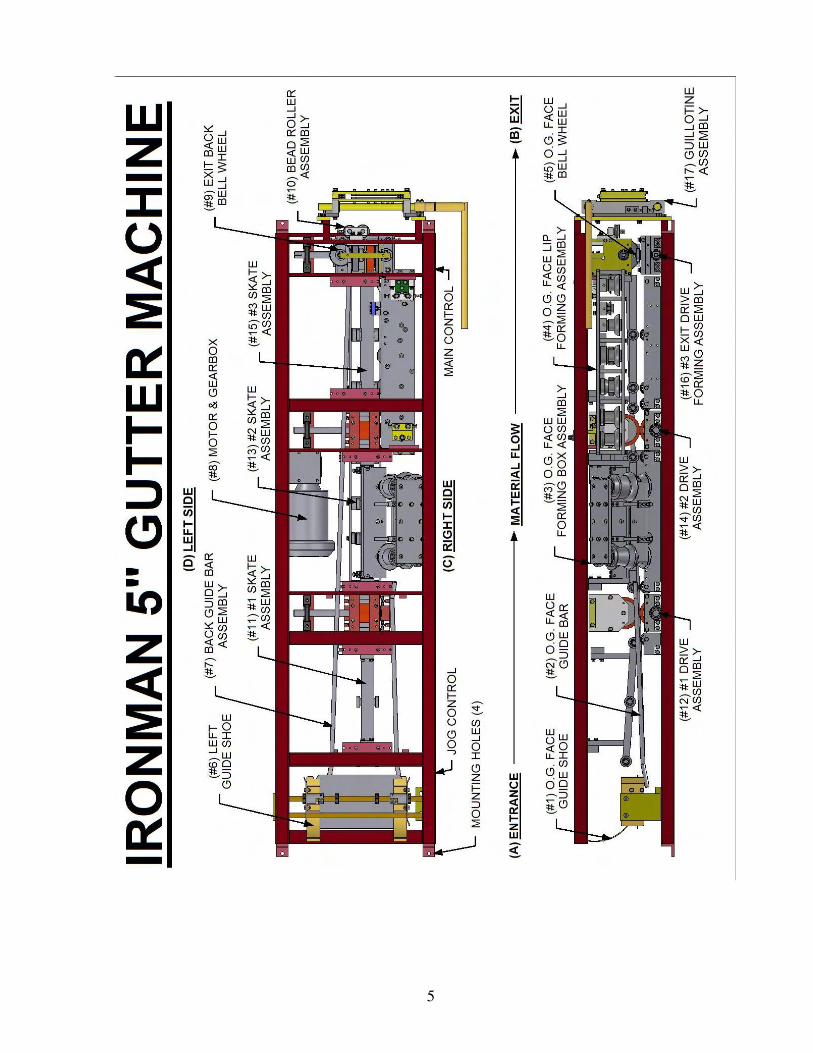
SECTION: 4 5” GUTTER MACHINE ORIENTATION
For communication purposes in the manual, the machine orientation is as follows: (SEE PG. 4)
A. ENTRANCE
The ENTRANCE of the machine is where the forming process begins and where the material is fed.
B. EXIT The EXIT of the machine is where the forming process is complete and where the finished gutter exits the machine.
C. RIGHT SIDE
The RIGHT SIDE is determined by facing the entrance end of the machine.
The RIGHT SIDE of the machine is where the O.G or face side gutter is formed.
COMPONENTS ON RIGHT SIDE:
1. O.G. FACE GUIDE SHOE (RIGHT SHOE)
2. O.G. FACE GUIDE BAR ASSEMBLY
3. O.G. FACE FORMING BOX ASSEMBLY
4. O.G. FACE LIP FORMING BOX ASSEMBLY
5. O.G. FACE BELL ROLLER
D. LEFT SIDE The LEFT SIDE is determined by facing the entrance end of the machine.
The LEFT SIDE of the machine is where the back of the gutter is formed.
COMPONENTS ON LEFT SIDE: 6. BACK GUIDE SHOE (LEFT SHOE)
7. BACK GUIDE BAR ASSEMBLY
8. MOTOR AND GEAR BOX
9. BACK BELL EXIT ROLLER
10. BEAD ROLLER ASSEMBLY
E. CENTER of MACHINE The CENTER of the machine forms the bottom section of gutter- drive assembly.
COMPONENTS IN CENTER OF MACHINE 11. #1 SKATE ASSEMBLY
12. #1 DRIVE ASSEMBLY
13. #2 SKATE ASSEMBLY
14. #2 DRIVE ASSEMBLY
15. #3 SKATE ASSEMBLY
16. #3 TOP & BOTTOM DRIVE FORMING STATION
17. GUILLOTINE ASSEMBLY
5
6
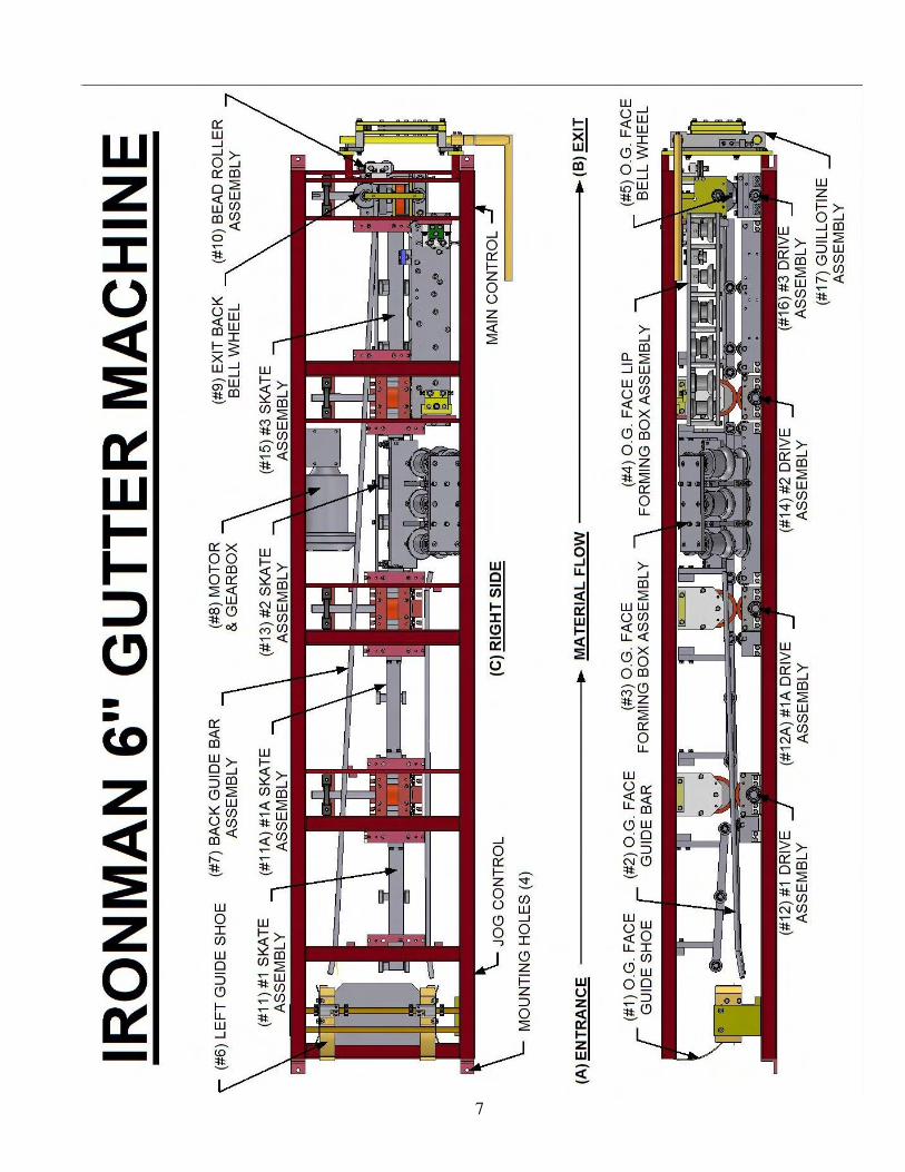
SECTION: 4A 6” GUTTER MACHINE ORIENTATION
For communication purposes in the manual, the machine orientation is as follows: (SEE PG. 6)
A. ENTRANCE
The ENTRANCE is where the forming process begins and where the material is fed.
B. EXIT
The EXIT is where the forming process is complete and where the finished gutter exits the machine.
C. RIGHT SIDE
The RIGHT SIDE of the machine is determined by facing the entrance end of machine.
The RIGHT SIDE of the machine is where the O.G or face side of gutter is formed.
COMPONENTS ON RIGHT SIDE: 1. O.G. FACE GUIDE SHOE (RIGHT SHOE)
2. O.G. FACE GUIDE BAR ASSEMBLY
3. O.G. FACE FORMING BOX ASSEMBLY
4. O.G. FACE LIP FORMING BOX ASSEMBLY
5. O.G. FACE BELL ROLLER
D. LEFT SIDE The LEFT SIDE of the machine is determined by facing the entrance end of machine.
The LEFT SIDE of the machine is where the back of the gutter is formed.
COMPONENTS ON LEFT SIDE: 6. BACK GUIDE SHOE (LEFT SHOE)
7. BACK GUIDE BAR ASSEMBLY
8. MOTOR AND GEAR BOX
9. EXIT BACK BELL ROLLER
10. BEAD ROLLER ASSEMBLY
E. CENTER of MACHINE The CENTER of the machine forms bottom section of gutter- drive assembly.
COMPONENTS IN CENTER OF MACHINE: 11. #1 SKATE ASSEMBLY
12. #1 DRIVE ASSEMBLY
11A. #1A SKATE ASSEMBLY
12A. #1A DRIVE ASSEMBLY
13. #2 SKATE ASSEMBLY
14. #2 DRIVE ASSEMBLY
15. #3 SKATE ASSEMBLY
16. #3 TOP & BOTTOM DRIVE FORMING STATION
17. GUILLOTINE ASSEMBLY
NOTES: _______________________________________________________________________________________
_______________________________________________________________________________________
_______________________________________________________________________________________
_______________________________________________________________________________________
_______________________________________________________________________________________
_______________________________________________________________________________________
7
8
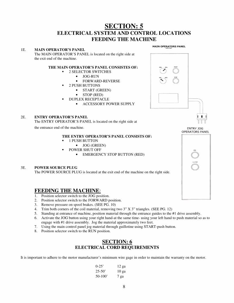
SECTION: 5 ELECTRICAL SYSTEM AND CONTROL LOCATIONS
FEEDING THE MACHINE
1E. MAIN OPERATOR’S PANEL
The MAIN OPERATOR’S PANEL is located on the right side at
the exit end of the machine.
THE MAIN OPERATOR’S PANEL CONSISTES OF:
� 2 SELECTOR SWITCHES
• JOG-RUN
• FORWARD-REVERSE
� 2 PUSH BUTTONS
• START (GREEN)
• STOP (RED)
� DUPLEX RECEPTACLE
• ACCESSORY POWER SUPPLY
2E. ENTRY OPERATOR’S PANEL
The ENTRY OPERATOR’S PANEL is located on the right side at
the entrance end of the machine.
THE ENTRY OPERATOR’S PANEL CONSISTS OF: � 1 PUSH BUTTON
• JOG (GREEN)
� POWER SHUT OFF
• EMERGENCY STOP BUTTON (RED)
3E. POWER SOURCE PLUG
The POWER SOURCE PLUG is located at the exit end of the machine on the right side.
FEEDING THE MACHINE: 1. Position selector switch to the JOG position.
2. Position selector switch to the FORWARD position.
3. Remove pressure on spool brakes. (SEE PG. 10)
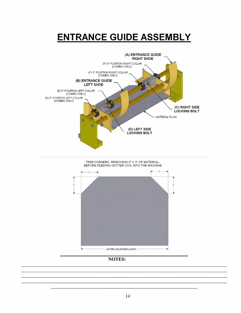
4. Trim both corners of the coil material, removing two 3” X 3” triangles. (SEE PG. 12)
5. Standing at entrance of machine, position material through the entrance guides to the #1 drive assembly.
6. Activate the JOG button using your right hand-at the same time- using your left hand to push material so as to
engage with #1 drive assembly. Jog the material approximately two feet.
7. Using the main control panel jog material through guillotine using START-push button.
8. Position selector switch to the RUN position.
SECTION: 6 ELECTRICAL CORD REQUIREMENTS
It is important to adhere to the motor manufacturer’s minimum wire gage in order to maintain the warranty on the motor.
0-25’ 12 ga
25-50’ 10 ga
50-100’ 7 ga
9
10

11
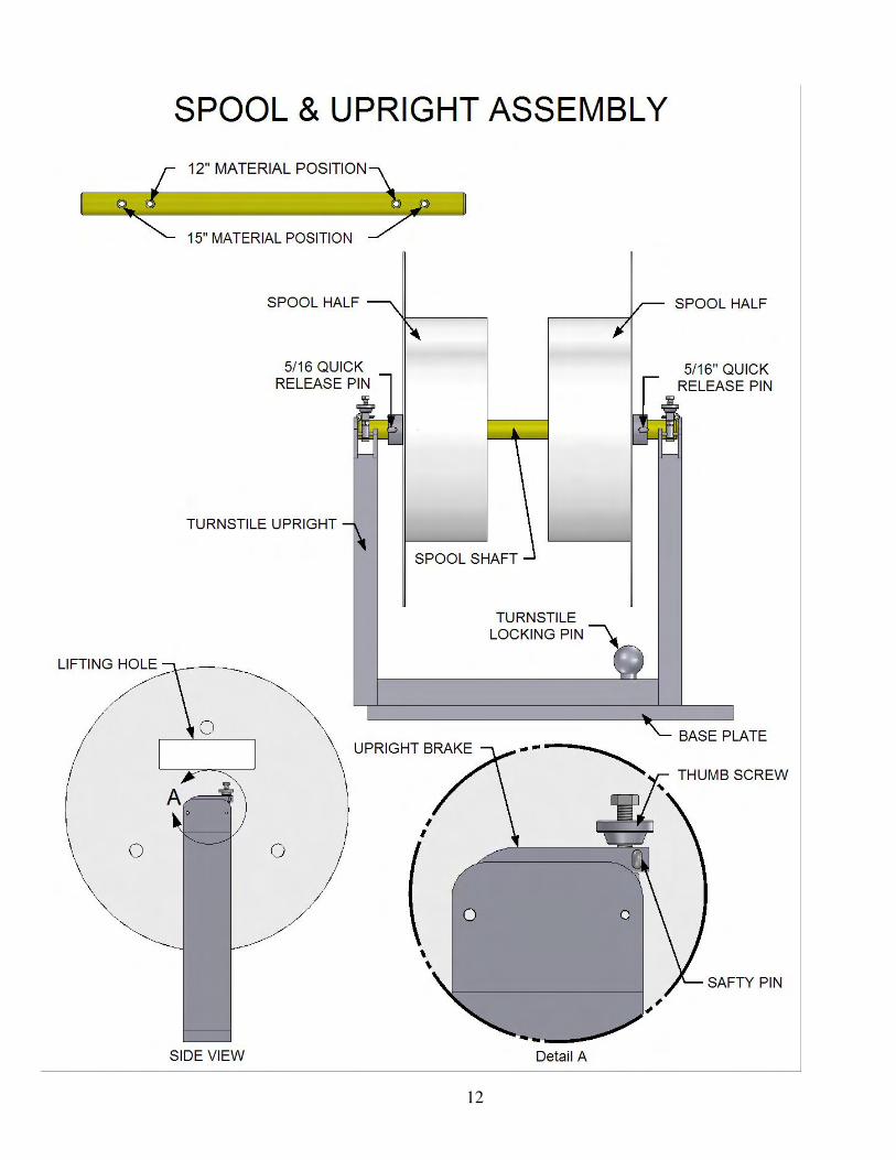
SECTION: 7 SPOOL UPRIGHT SUPPORTS
The IRONMAN TURNSTILE UPRIGHT is a modular turnstile support used to hold coil.
Your machine may have up to three uprights.
ONE TURNSTILE UPRIGHT ASSEMBLY CONSISTS OF: (SEE PG. 11)
TO ROTATE TURNSTILE FOR TWO-SIDED COIL:
1. Disengage the TURNSTILE LOCKING PIN.
2. Rotate TURNSTILE 180 degrees.
3. Re-engage the TURNSTILE LOCKING PIN.
SECTION: 8 SPOOL ASSEMBLY AND LOADING COIL
ONE SPOOL ASSEMBLY CONSISTS OF: (SEE PG. 11)
SPOOL SHAFT (1) SPOOL HALF (1) 5/16” QUICK RELEASE PIN (2)
TO LOAD COIL ONTO SPOOL ASSEMBLY: 1. Place the empty spool assembly on the ground or on a flat surface.
2. Remove one of the 5/16” quick release pins.
3. Slide the spool half off of the ¼” spool shaft.
4. Insert the spool shaft through the center of the coil.
5. Replace spool half on the spool shaft, and reinstall the 5/16” quick release pin.
6. The spool assembly and coil are now ready to load onto the upright.
NOTE: The spool assembly is adjustable to accept both 5” gutter material (11 ¾” – 12”) and 6” gutter material (15”).
PLACING SPOOL & COIL IN THE UPRIGHT: Use an approved lifting device in the designated spool lifting area to position the spool assembly into the turnstile upright.
(IMPORTANT! – Please read PRECAUTIONS)
PRECAUTIONS:
� Make sure loading area is clean and clear of debris.
� Make sure Turnstile Locking Pin is securely installed.
� Always wear protective footwear when handling coil.
� Never load coil with the brake in closed position.
� Never operate machine without first checking brake & pin positions.
� Never transport machine without locking brake in closed position.
TURNSTILE UPRIGHT (1) TENSION BRAKE (2)
BASE PLATE (1) THUMB SCREW (2)
TURNSTILE LOCKING PIN (1) SAFETY PIN (2)
12
13
SECTION: 9 ENTRANCE GUIDE SYSTEM
PURPOSE AND PRECAUTIONS OF THE ENTRANCE GUIDE SYSTEM: The ENTRANCE GUIDE system is a very important part of this machine. Not only is it used to position material
being fed into the machine, but it also controls the lateral relationship of the material to the forming stations.
ENTRANCE GUIDE CONSISTS OF: (SEE PG. 13)
A. RIGHT ENTRANCE GUIDE SHOE
B. LEFT ENTRANCE GUIDE SHOE
C. RIGHT LOCKING BOLT
D. LEFT LOCKING BOLT
E. LEFT LOCKING COLLARS (5” & 6” POSITIONING STOPS)
F. RIGHT LOCKING COLLARS (5” & 6” POSITIONING STOPS)
ENTRANCE GUIDE ASSESSMENT:
� The RIGHT ENTRY GUIDE (A) controls the amount of material that is fed into the face box and lip box roller
assemblies. It should be moved ONLY to increase or decrease the amount of lip turned under.
� If an adjustment is made on the RIGHT ENTRY GUIDE (A), an adjustment must be made on the LEFT ENTRY
GUIDE (B) using coil as a guide. There should be no visible play between the entry guides and the coil. The guide
should not be so tight that it would cause the gutter to bind in the entry guide assembly.
� Before moving the RIGHT ENTRY GUIDE (A), always take a measurement from the inside edge of the entry guide
(where the coil will ride) to the inside edge of the frame. This will give a reference point to measure and move
from. You can easily return to your original location if you move the guide in the wrong direction.
TO MOVE THE GUIDES: 1. Loosen the bolt on the locking collars (C or D).
2. Move guide
A. To INCREASE the amount of lip turned under, Move the guides toward the RIGHT side (FACE side) of the machine.
B. To DECREASE the amount of lip turned under, Move the guides toward the LEFT side (BACK side) of the machine.
3. Retighten the cap screw.
ENTRANCE GUIDE OPERATION:
When feeding material from the spools on the top of the machine or from a remote station, feed the material straight
into the entry guides. DO NOT FORCE. Continue pushing material into the machine until it stops. The material
can now be jogged through the machine. If the first drive roller does not pull the material into the machine, give the
material a little push from the entrance end while continuing to jog the material into the machine.
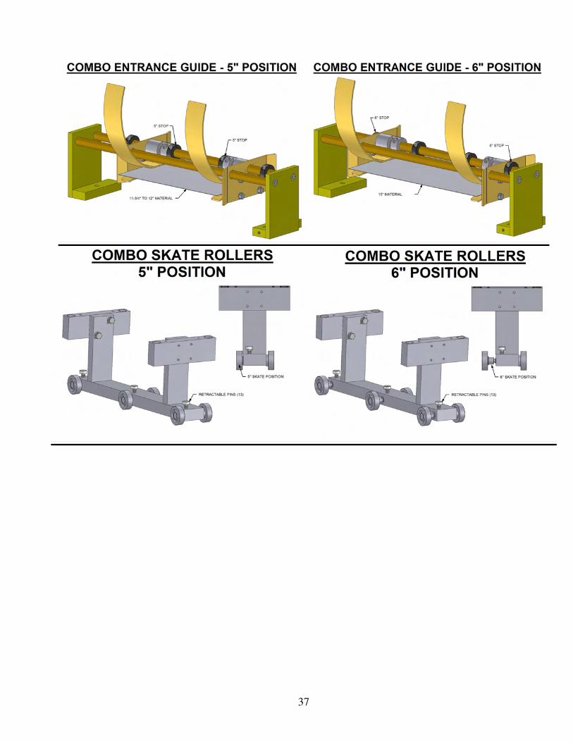
ADJUSTMENT FOR COMBO MACHINE ENTRANCE GUIDES:
a. CHANGING ENTRANCE GUIDES FROM 5” TO 6”:
i. TO MOVE RIGHT GUIDE, loosen LOCKING BOLT C, move guide to the right.
Stop at 6” collar, and tighten BOLT C.
ii. TO MOVE LEFT GUIDE, loosen LOCKING BOLT D, move guide to the left
Stop at 6” collar, and tighten BOLT D.
b. CHANGING ENTRANCE GUIDES FROM 6” TO 5”: i. TO MOVE RIGHT GUIDE, loosen LOCKING BOLT C, move guide to the left.
Stop at 5” collar, and tighten BOLT C.
ii. TO MOVE LEFT GUIDE, loosen LOCKING BOLT D, move guide to the right
Stop at 5” collar, and tighten BOLT D.
14
NOTES:
_______________________________________________________________________________________
_______________________________________________________________________________________
_______________________________________________________________________________________
_______________________________________________________________________________________
______________________________________________________________
15
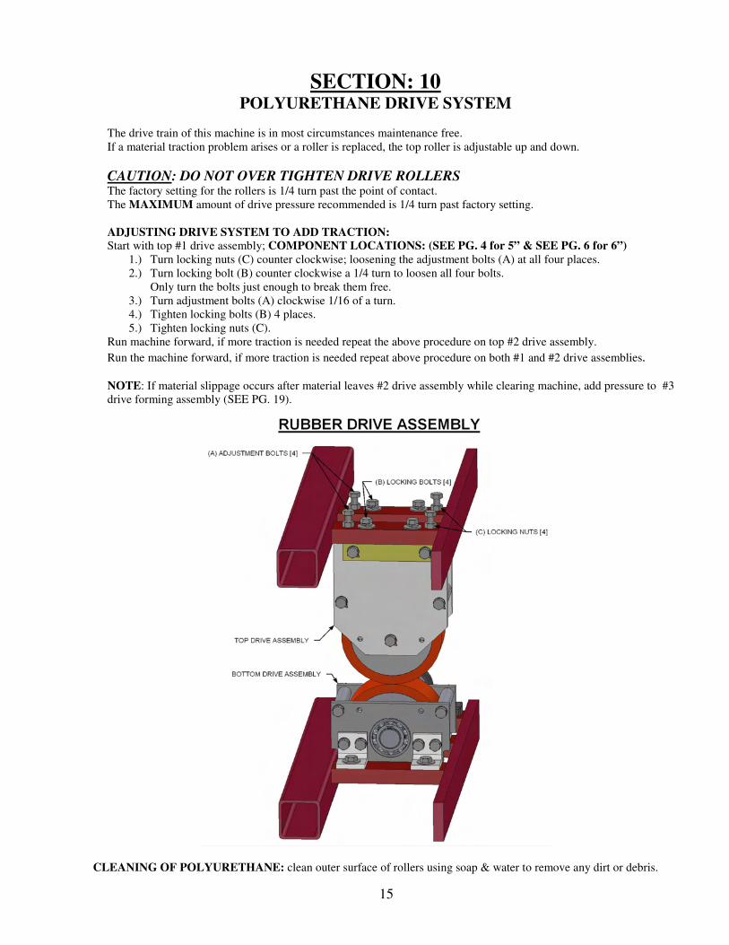
SECTION: 10 POLYURETHANE DRIVE SYSTEM
The drive train of this machine is in most circumstances maintenance free.
If a material traction problem arises or a roller is replaced, the top roller is adjustable up and down.
CAUTION: DO NOT OVER TIGHTEN DRIVE ROLLERS
The factory setting for the rollers is 1/4 turn past the point of contact.
The MAXIMUM amount of drive pressure recommended is 1/4 turn past factory setting.
ADJUSTING DRIVE SYSTEM TO ADD TRACTION:
Start with top #1 drive assembly; COMPONENT LOCATIONS: (SEE PG. 4 for 5” & SEE PG. 6 for 6”)
1.) Turn locking nuts (C) counter clockwise; loosening the adjustment bolts (A) at all four places.
2.) Turn locking bolt (B) counter clockwise a 1/4 turn to loosen all four bolts.
Only turn the bolts just enough to break them free.
3.) Turn adjustment bolts (A) clockwise 1/16 of a turn.
4.) Tighten locking bolts (B) 4 places.
5.) Tighten locking nuts (C).
Run machine forward, if more traction is needed repeat the above procedure on top #2 drive assembly.
Run the machine forward, if more traction is needed repeat above procedure on both #1 and #2 drive assemblies.
NOTE: If material slippage occurs after material leaves #2 drive assembly while clearing machine, add pressure to #3
drive forming assembly (SEE PG. 19).
CLEANING OF POLYURETHANE: clean outer surface of rollers using soap & water to remove any dirt or debris.
16
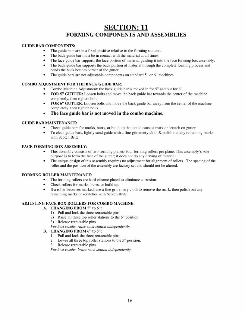
SECTION: 11 FORMING COMPONENTS AND ASSEMBLIES
GUIDE BAR COMPONENTS:
• The guide bars are in a fixed positive relative to the forming stations.
• The back guide bar must be in contact with the material at all times.
• The face guide bar supports the face portion of material guiding it into the face forming box assembly.
• The back guide bar supports the back portion of material through the complete forming process and
bends the back bottom corner of the gutter.
• The guide bars are not adjustable components on standard 5” or 6” machines.
COMBO ADJUSTMENT FOR THE BACK GUIDE BAR:
• Combo Machine Adjustment: the back guide bar is moved in for 5” and out for 6”.
• FOR 5” GUTTER: Loosen bolts and move the back guide bar towards the center of the machine
completely, then tighten bolts
• FOR 6” GUTTER: Loosen bolts and move the back guide bar away from the center of the machine
completely, then tighten bolts.
• The face guide bar is not moved in the combo machine.
GUIDE BAR MAINTENANCE:
• Check guide bars for marks, burrs, or build up that could cause a mark or scratch on gutter.
• To clean guide bars, lightly sand guide with a fine grit emery cloth & polish out any remaining marks
with Scotch Brite.
FACE FORMING BOX ASSEMBLY:
• This assembly consists of two forming planes- four forming rollers per plane. This assembly’s sole
purpose is to form the face of the gutter; it does not do any driving of material.
• The unique design of this assembly requires no adjustment for alignment of rollers. The spacing of the
roller and the position of the assembly are factory set and should not be altered.
FORMING ROLLER MAINTENANCE:
• The forming rollers are hard chrome plated to eliminate corrosion.
• Check rollers for marks, burrs, or build up.
• If a roller becomes marked, use a fine grit emery cloth to remove the mark, then polish out any
remaining marks or scratches with Scotch Brite.
ADJUSTING FACE BOX ROLLERS FOR COMBO MACHINE:
A. CHANGING FROM 5” to 6”: 1) Pull and lock the three retractable pins.
2) Raise all three top roller stations to the 6” position
3) Release retractable pins.
For best results, raise each station independently.
B. CHANGING FROM 6” to 5”:
1. Pull and lock the three retractable pins.
2. Lower all three top roller stations to the 5” position.
3. Release retractable pins.
For best results, lower each station independently.
17
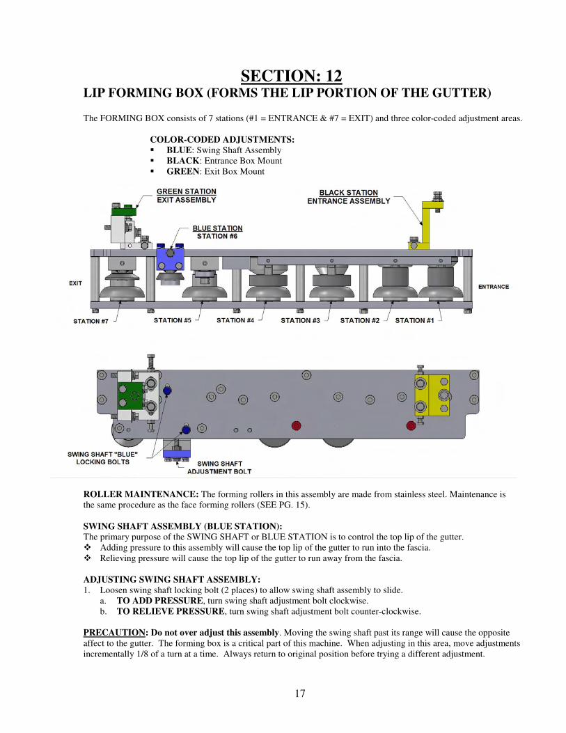
SECTION: 12 LIP FORMING BOX (FORMS THE LIP PORTION OF THE GUTTER)
The FORMING BOX consists of 7 stations (#1 = ENTRANCE & #7 = EXIT) and three color-coded adjustment areas.
COLOR-CODED ADJUSTMENTS:
� BLUE: Swing Shaft Assembly
� BLACK: Entrance Box Mount
� GREEN: Exit Box Mount
ROLLER MAINTENANCE: The forming rollers in this assembly are made from stainless steel. Maintenance is
the same procedure as the face forming rollers (SEE PG. 15).
SWING SHAFT ASSEMBLY (BLUE STATION): The primary purpose of the SWING SHAFT or BLUE STATION is to control the top lip of the gutter.
� Adding pressure to this assembly will cause the top lip of the gutter to run into the fascia.
� Relieving pressure will cause the top lip of the gutter to run away from the fascia.
ADJUSTING SWING SHAFT ASSEMBLY:
1. Loosen swing shaft locking bolt (2 places) to allow swing shaft assembly to slide.
a. TO ADD PRESSURE, turn swing shaft adjustment bolt clockwise.
b. TO RELIEVE PRESSURE, turn swing shaft adjustment bolt counter-clockwise.
PRECAUTION: Do not over adjust this assembly. Moving the swing shaft past its range will cause the opposite
affect to the gutter. The forming box is a critical part of this machine. When adjusting in this area, move adjustments
incrementally 1/8 of a turn at a time. Always return to original position before trying a different adjustment.
18
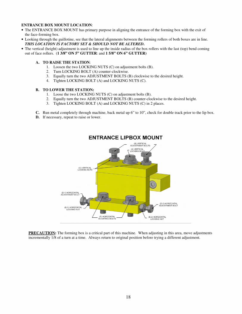
ENTRANCE BOX MOUNT LOCATION:
• The ENTRANCE BOX MOUNT has primary purpose in aligning the entrance of the forming box with the exit of
the face-forming box.
• Looking through the guillotine, see that the lateral alignments between the forming rollers of both boxes are in line.
THIS LOCATION IS FACTORY SET & SHOULD NOT BE ALTERED.
• The vertical (height) adjustment is used to line up the inside radius of the box rollers with the last (top) bend coming
out of face rollers. (1 3/8” ON 5” GUTTER: and 1 5/8” ON 6” GUTTER)
A. TO RAISE THE STATION:
1. Loosen the two LOCKING NUTS (C) on adjustment bolts (B).
2. Turn LOCKING BOLT (A) counter-clockwise.
3. Equally turn the two ADJUSTMENT BOLTS (B) clockwise to the desired height.
4. Tighten LOCKING BOLT (A) and LOCKING NUTS (C).
B. TO LOWER THE STATION:
1. Loose the two LOCKING NUTS (C) on adjustment bolts (B).
2. Equally turn the two ADJUSTMENT BOLTS (B) counter-clockwise to the desired height.
3. Tighten LOCKING BOLT (A) and LOCKING NUTS (C) in 2 places.
C. Run metal completely through machine, back metal up 6” to 10”, check for double track prior to the lip box.
D. If necessary, repeat to raise or lower.
PRECAUTION: The forming box is a critical part of this machine. When adjusting in this area, move adjustments
incrementally 1/8 of a turn at a time. Always return to original position before trying a different adjustment.
19
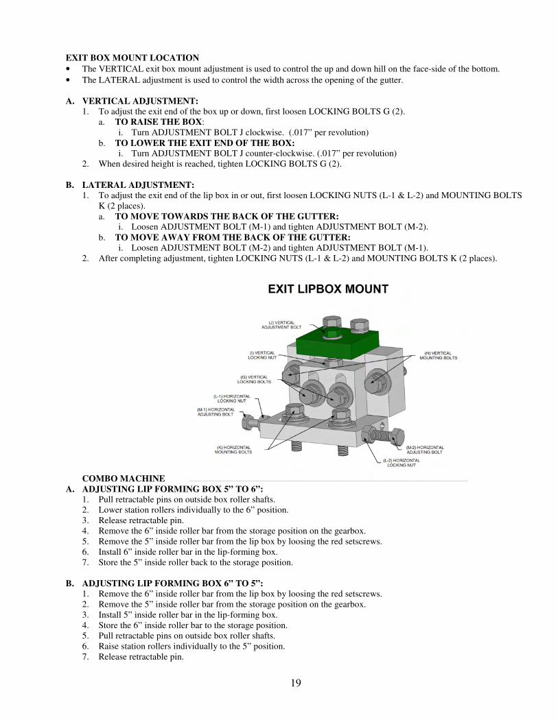
EXIT BOX MOUNT LOCATION
• The VERTICAL exit box mount adjustment is used to control the up and down hill on the face-side of the bottom.
• The LATERAL adjustment is used to control the width across the opening of the gutter.
A. VERTICAL ADJUSTMENT:
1. To adjust the exit end of the box up or down, first loosen LOCKING BOLTS G (2).
a. TO RAISE THE BOX:
i. Turn ADJUSTMENT BOLT J clockwise. (.017” per revolution)
b. TO LOWER THE EXIT END OF THE BOX: i. Turn ADJUSTMENT BOLT J counter-clockwise. (.017” per revolution)
2. When desired height is reached, tighten LOCKING BOLTS G (2).
B. LATERAL ADJUSTMENT:
1. To adjust the exit end of the lip box in or out, first loosen LOCKING NUTS (L-1 & L-2) and MOUNTING BOLTS
K (2 places).
a. TO MOVE TOWARDS THE BACK OF THE GUTTER:
i. Loosen ADJUSTMENT BOLT (M-1) and tighten ADJUSTMENT BOLT (M-2).
b. TO MOVE AWAY FROM THE BACK OF THE GUTTER:
i. Loosen ADJUSTMENT BOLT (M-2) and tighten ADJUSTMENT BOLT (M-1).
2. After completing adjustment, tighten LOCKING NUTS (L-1 & L-2) and MOUNTING BOLTS K (2 places).
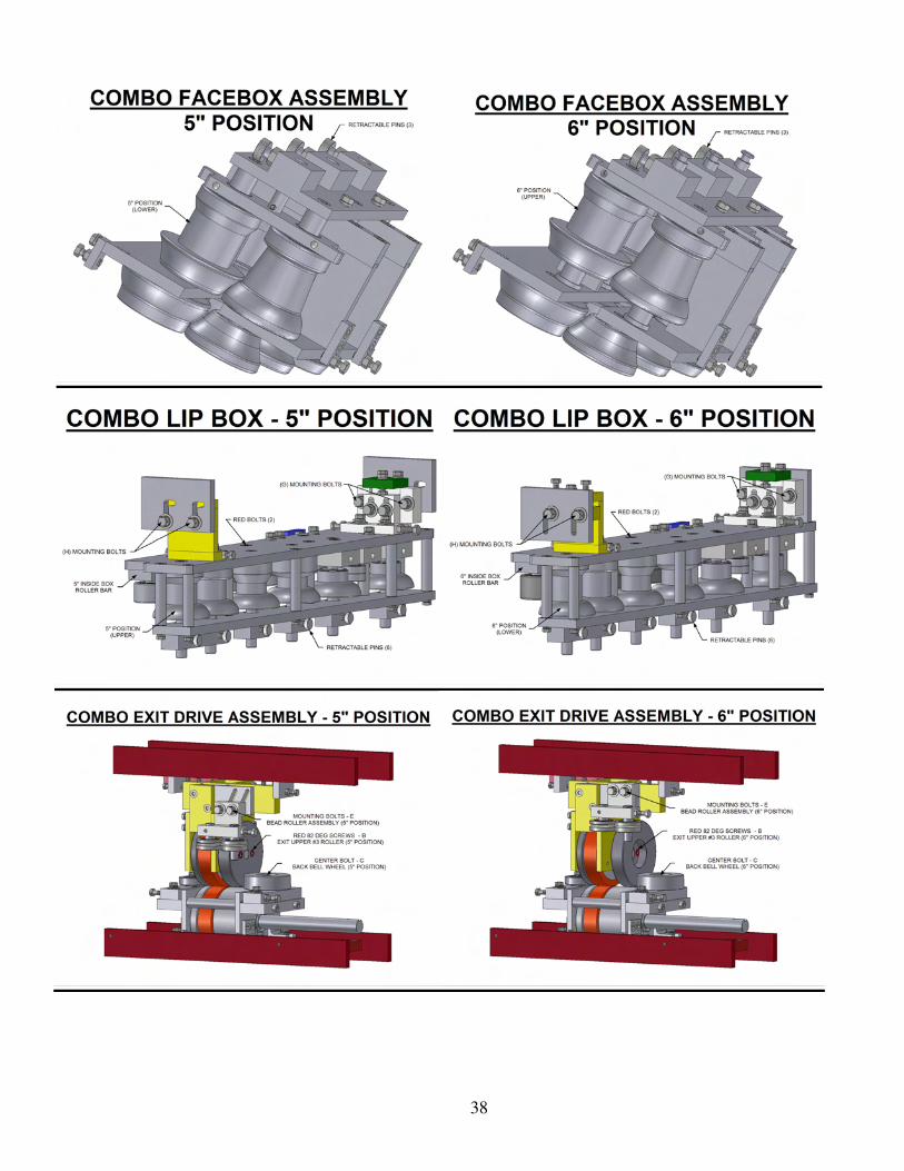
COMBO MACHINE
A. ADJUSTING LIP FORMING BOX 5” TO 6”:
1. Pull retractable pins on outside box roller shafts.
2. Lower station rollers individually to the 6” position.
3. Release retractable pin.
4. Remove the 6” inside roller bar from the storage position on the gearbox.
5. Remove the 5” inside roller bar from the lip box by loosing the red setscrews.
6. Install 6” inside roller bar in the lip-forming box.
7. Store the 5” inside roller back to the storage position.
B. ADJUSTING LIP FORMING BOX 6” TO 5”:
1. Remove the 6” inside roller bar from the lip box by loosing the red setscrews.
2. Remove the 5” inside roller bar from the storage position on the gearbox.
3. Install 5” inside roller bar in the lip-forming box.
4. Store the 6” inside roller bar to the storage position.
5. Pull retractable pins on outside box roller shafts.
6. Raise station rollers individually to the 5” position.
7. Release retractable pin.
20
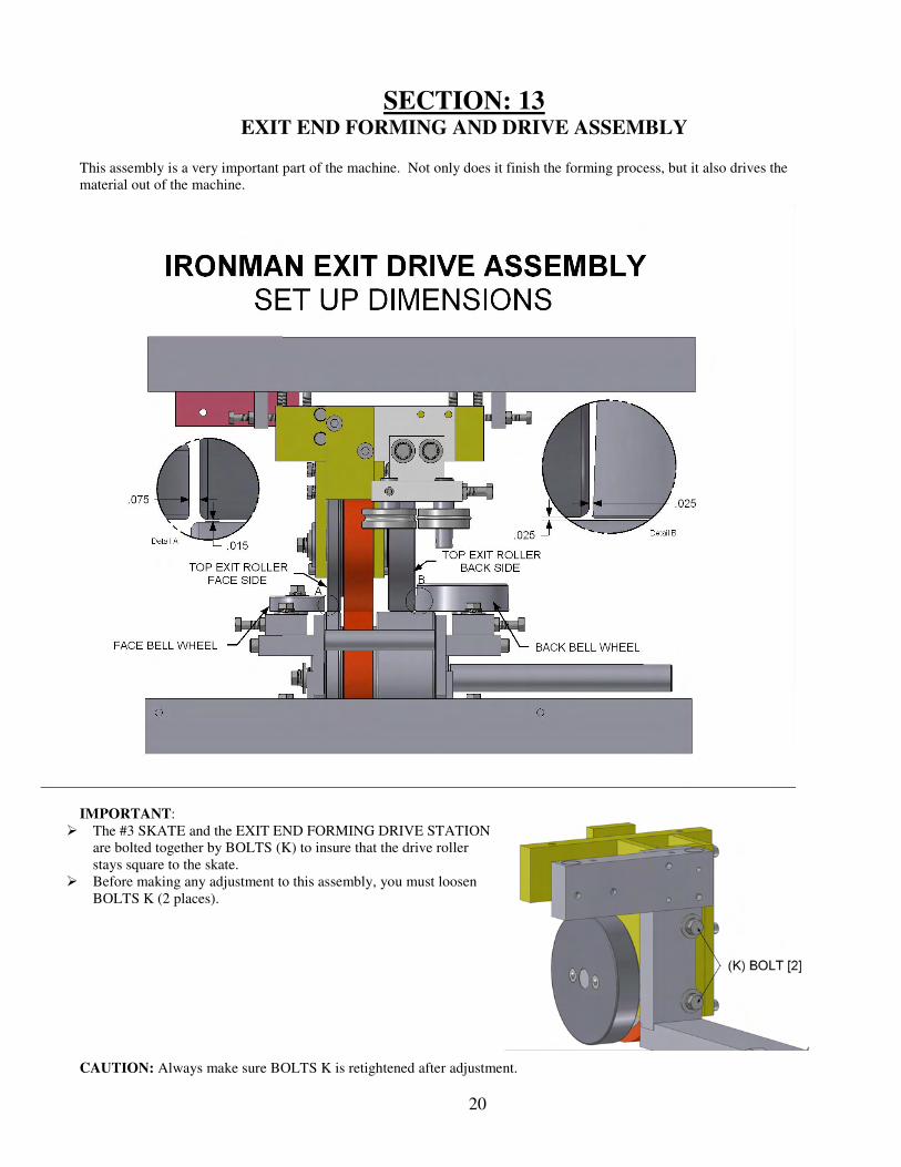
SECTION: 13 EXIT END FORMING AND DRIVE ASSEMBLY
This assembly is a very important part of the machine. Not only does it finish the forming process, but it also drives the
material out of the machine.
IMPORTANT:
� The #3 SKATE and the EXIT END FORMING DRIVE STATION
are bolted together by BOLTS (K) to insure that the drive roller
stays square to the skate.
� Before making any adjustment to this assembly, you must loosen
BOLTS K (2 places).
CAUTION: Always make sure BOLTS K is retightened after adjustment.
21
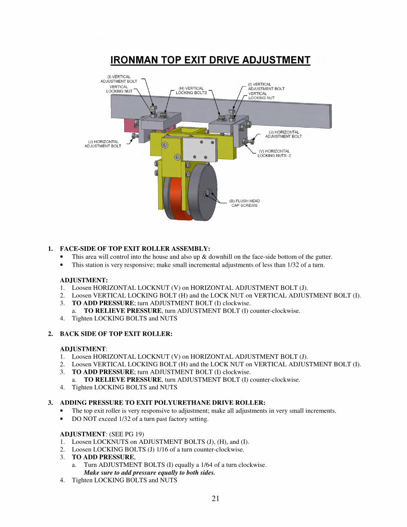
1. FACE-SIDE OF TOP EXIT ROLLER ASSEMBLY:
• This area will control into the house and also up & downhill on the face-side bottom of the gutter.
• This station is very responsive; make small incremental adjustments of less than 1/32 of a turn.
ADJUSTMENT: 1. Loosen HORIZONTAL LOCKNUT (V) on HORIZONTAL ADJUSTMENT BOLT (J).
2. Loosen VERTICAL LOCKING BOLT (H) and the LOCK NUT on VERTICAL ADJUSTMENT BOLT (I).
3. TO ADD PRESSURE; turn ADJUSTMENT BOLT (I) clockwise.
a. TO RELIEVE PRESSURE, turn ADJUSTMENT BOLT (I) counter-clockwise.
4. Tighten LOCKING BOLTS and NUTS
2. BACK SIDE OF TOP EXIT ROLLER:
ADJUSTMENT:
1. Loosen HORIZONTAL LOCKNUT (V) on HORIZONTAL ADJUSTMENT BOLT (J).
2. Loosen VERTICAL LOCKING BOLT (H) and the LOCK NUT on VERTICAL ADJUSTMENT BOLT (I).
3. TO ADD PRESSURE; turn ADJUSTMENT BOLT (I) clockwise.
a. TO RELIEVE PRESSURE, turn ADJUSTMENT BOLT (I) counter-clockwise.
4. Tighten LOCKING BOLTS and NUTS
3. ADDING PRESSURE TO EXIT POLYURETHANE DRIVE ROLLER:
• The top exit roller is very responsive to adjustment; make all adjustments in very small increments.
• DO NOT exceed 1/32 of a turn past factory setting.
ADJUSTMENT: (SEE PG 19)
1. Loosen LOCKNUTS on ADJUSTMENT BOLTS (J), (H), and (I).
2. Loosen LOCKING BOLTS (J) 1/16 of a turn counter-clockwise.
3. TO ADD PRESSURE,
a. Turn ADJUSTMENT BOLTS (I) equally a 1/64 of a turn clockwise.
Make sure to add pressure equally to both sides.
4. Tighten LOCKING BOLTS and NUTS
22
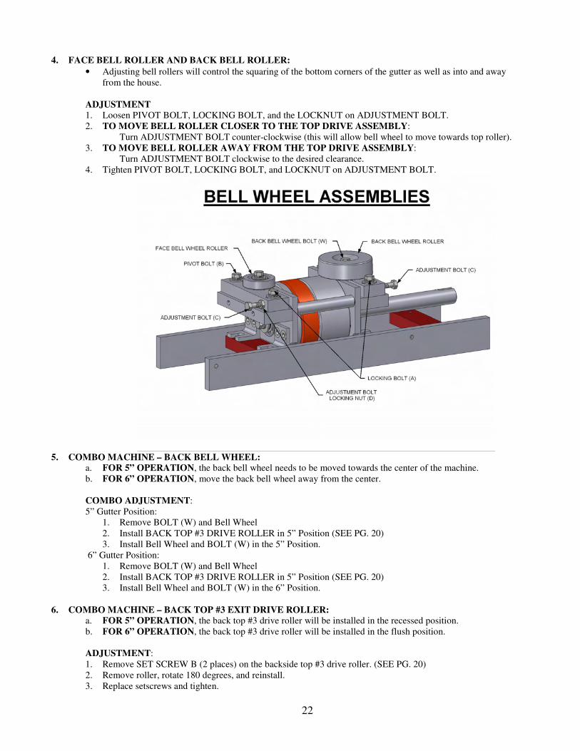
4. FACE BELL ROLLER AND BACK BELL ROLLER:
• Adjusting bell rollers will control the squaring of the bottom corners of the gutter as well as into and away
from the house.
ADJUSTMENT
1. Loosen PIVOT BOLT, LOCKING BOLT, and the LOCKNUT on ADJUSTMENT BOLT.
2. TO MOVE BELL ROLLER CLOSER TO THE TOP DRIVE ASSEMBLY:
Turn ADJUSTMENT BOLT counter-clockwise (this will allow bell wheel to move towards top roller).
3. TO MOVE BELL ROLLER AWAY FROM THE TOP DRIVE ASSEMBLY:
Turn ADJUSTMENT BOLT clockwise to the desired clearance.
4. Tighten PIVOT BOLT, LOCKING BOLT, and LOCKNUT on ADJUSTMENT BOLT.
5. COMBO MACHINE – BACK BELL WHEEL:
a. FOR 5” OPERATION, the back bell wheel needs to be moved towards the center of the machine.
b. FOR 6” OPERATION, move the back bell wheel away from the center.
COMBO ADJUSTMENT:
5” Gutter Position:
1. Remove BOLT (W) and Bell Wheel
2. Install BACK TOP #3 DRIVE ROLLER in 5” Position (SEE PG. 20)
3. Install Bell Wheel and BOLT (W) in the 5” Position.
6” Gutter Position:
1. Remove BOLT (W) and Bell Wheel
2. Install BACK TOP #3 DRIVE ROLLER in 5” Position (SEE PG. 20)
3. Install Bell Wheel and BOLT (W) in the 6” Position.
6. COMBO MACHINE – BACK TOP #3 EXIT DRIVE ROLLER:
a. FOR 5” OPERATION, the back top #3 drive roller will be installed in the recessed position.
b. FOR 6” OPERATION, the back top #3 drive roller will be installed in the flush position.
ADJUSTMENT:
1. Remove SET SCREW B (2 places) on the backside top #3 drive roller. (SEE PG. 20)
2. Remove roller, rotate 180 degrees, and reinstall.
3. Replace setscrews and tighten.
23
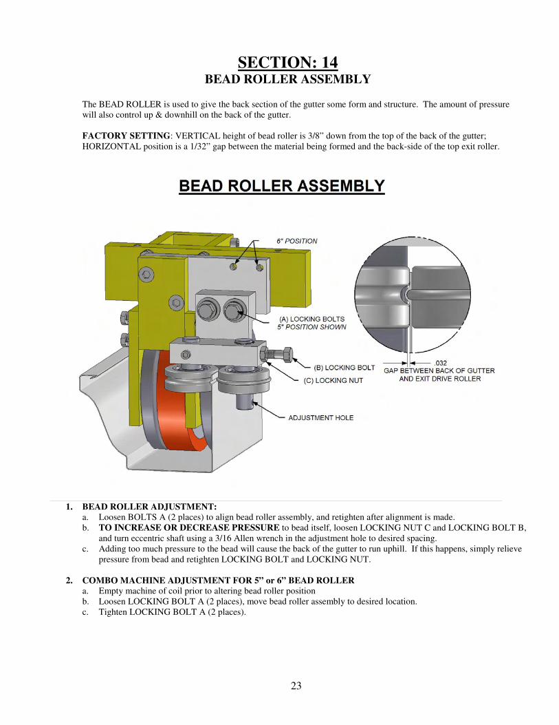
SECTION: 14 BEAD ROLLER ASSEMBLY
The BEAD ROLLER is used to give the back section of the gutter some form and structure. The amount of pressure
will also control up & downhill on the back of the gutter.
FACTORY SETTING: VERTICAL height of bead roller is 3/8” down from the top of the back of the gutter;
HORIZONTAL position is a 1/32” gap between the material being formed and the back-side of the top exit roller.
1. BEAD ROLLER ADJUSTMENT:
a. Loosen BOLTS A (2 places) to align bead roller assembly, and retighten after alignment is made.
b. TO INCREASE OR DECREASE PRESSURE to bead itself, loosen LOCKING NUT C and LOCKING BOLT B,
and turn eccentric shaft using a 3/16 Allen wrench in the adjustment hole to desired spacing.
c. Adding too much pressure to the bead will cause the back of the gutter to run uphill. If this happens, simply relieve
pressure from bead and retighten LOCKING BOLT and LOCKING NUT.
2. COMBO MACHINE ADJUSTMENT FOR 5” or 6” BEAD ROLLER a. Empty machine of coil prior to altering bead roller position
b. Loosen LOCKING BOLT A (2 places), move bead roller assembly to desired location.
c. Tighten LOCKING BOLT A (2 places).
24
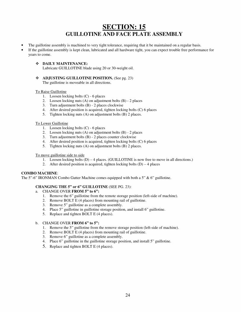
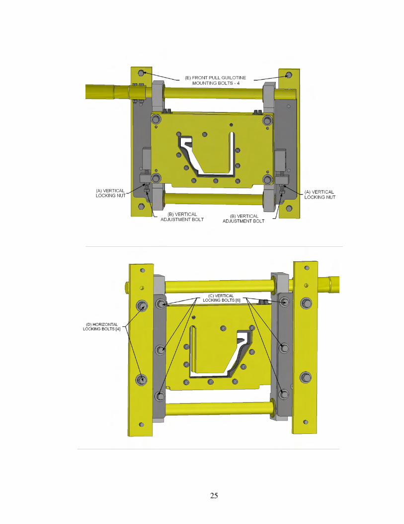
SECTION: 15 GUILLOTINE AND FACE PLATE ASSEMBLY
• The guillotine assembly is machined to very tight tolerance, requiring that it be maintained on a regular basis.
• If the guillotine assembly is kept clean, lubricated and all hardware tight, you can expect trouble free performance for
years to come.
� DAILY MAINTENANCE:
Lubricate GUILLOTINE blade using 20 or 30-weight oil.
� ADJUSTING GUILLOTINE POSITION. (See pg. 23)
The guillotine is moveable in all directions.
To Raise Guillotine
1. Loosen locking bolts (C) - 6 places
2. Loosen locking nuts (A) on adjustment bolts (B) - 2 places
3. Turn adjustment bolts (B) - 2 places clockwise
4. After desired position is acquired, tighten locking bolts (C) 6 places
5. Tighten locking nuts (A) on adjustment bolts (B) 2 places.
To Lower Guillotine
1. Loosen locking bolts (C) - 6 places
2. Loosen locking nuts (A) on adjustment bolts (B) - 2 places
3. Turn adjustment bolts (B) - 2 places counter clockwise
4. After desired position is acquired, tighten locking bolts (C) 6 places
5. Tighten locking nuts (A) on adjustment bolts (B) 2 places.
To move guillotine side to side
1. Loosen locking bolts (D) – 4 places. (GUILLOTINE is now free to move in all directions.)
2. After desired position is acquired, tighten locking bolts (D) – 4 places
.
COMBO MACHINE:
The 5”-6” IRONMAN Combo Gutter Machine comes equipped with both a 5” & 6” guillotine.
CHANGING THE 5” or 6” GUILLOTINE (SEE PG. 23):
a. CHANGE OVER FROM 5” to 6”:
1. Remove the 6” guillotine from the remote storage position (left-side of machine).
2. Remove BOLT E (4 places) from mounting rail of guillotine.
3. Remove 5” guillotine as a complete assembly.
4. Place 5” guillotine in guillotine storage position, and install 6” guillotine.
5. Replace and tighten BOLT E (4 places).
b. CHANGE OVER FROM 6” to 5”:
1. Remove the 5” guillotine from the remove storage position (left-side of machine).
2. Remove BOLT E (4 places) from mounting rail of guillotine.
3. Remove 6” guillotine as a complete assembly.
4. Place 6” guillotine in the guillotine storage position, and install 5” guillotine.
5. Replace and tighten BOLT E (4 places).
25
26
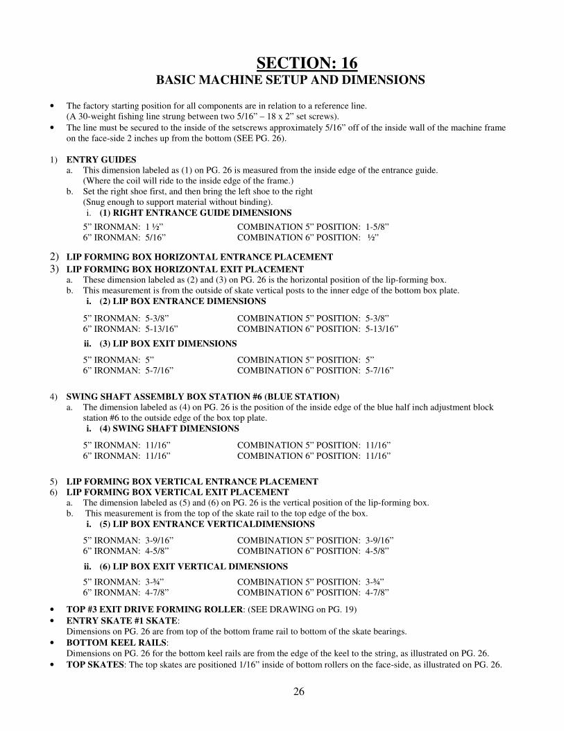
SECTION: 16 BASIC MACHINE SETUP AND DIMENSIONS
• The factory starting position for all components are in relation to a reference line.
(A 30-weight fishing line strung between two 5/16” – 18 x 2” set screws).
• The line must be secured to the inside of the setscrews approximately 5/16” off of the inside wall of the machine frame
on the face-side 2 inches up from the bottom (SEE PG. 26).
1) ENTRY GUIDES
a. This dimension labeled as (1) on PG. 26 is measured from the inside edge of the entrance guide.
(Where the coil will ride to the inside edge of the frame.)
b. Set the right shoe first, and then bring the left shoe to the right
(Snug enough to support material without binding).
i. (1) RIGHT ENTRANCE GUIDE DIMENSIONS
2) LIP FORMING BOX HORIZONTAL ENTRANCE PLACEMENT 3) LIP FORMING BOX HORIZONTAL EXIT PLACEMENT
a. These dimension labeled as (2) and (3) on PG. 26 is the horizontal position of the lip-forming box.
b. This measurement is from the outside of skate vertical posts to the inner edge of the bottom box plate.
i. (2) LIP BOX ENTRANCE DIMENSIONS
ii. (3) LIP BOX EXIT DIMENSIONS
4) SWING SHAFT ASSEMBLY BOX STATION #6 (BLUE STATION) a. The dimension labeled as (4) on PG. 26 is the position of the inside edge of the blue half inch adjustment block
station #6 to the outside edge of the box top plate.
i. (4) SWING SHAFT DIMENSIONS
5) LIP FORMING BOX VERTICAL ENTRANCE PLACEMENT
6) LIP FORMING BOX VERTICAL EXIT PLACEMENT
a. The dimension labeled as (5) and (6) on PG. 26 is the vertical position of the lip-forming box.
b. This measurement is from the top of the skate rail to the top edge of the box.
i. (5) LIP BOX ENTRANCE VERTICALDIMENSIONS
ii. (6) LIP BOX EXIT VERTICAL DIMENSIONS
• TOP #3 EXIT DRIVE FORMING ROLLER: (SEE DRAWING on PG. 19)
• ENTRY SKATE #1 SKATE:
Dimensions on PG. 26 are from top of the bottom frame rail to bottom of the skate bearings.
• BOTTOM KEEL RAILS:
Dimensions on PG. 26 for the bottom keel rails are from the edge of the keel to the string, as illustrated on PG. 26.
• TOP SKATES: The top skates are positioned 1/16” inside of bottom rollers on the face-side, as illustrated on PG. 26.
5” IRONMAN: 1 ½” COMBINATION 5” POSITION: 1-5/8”
6” IRONMAN: 5/16” COMBINATION 6” POSITION: ½”
5” IRONMAN: 5-3/8” COMBINATION 5” POSITION: 5-3/8”
6” IRONMAN: 5-13/16” COMBINATION 6” POSITION: 5-13/16”
5” IRONMAN: 5” COMBINATION 5” POSITION: 5”
6” IRONMAN: 5-7/16” COMBINATION 6” POSITION: 5-7/16”
5” IRONMAN: 11/16” COMBINATION 5” POSITION: 11/16”
6” IRONMAN: 11/16” COMBINATION 6” POSITION: 11/16”
5” IRONMAN: 3-9/16” COMBINATION 5” POSITION: 3-9/16”
6” IRONMAN: 4-5/8” COMBINATION 6” POSITION: 4-5/8”
5” IRONMAN: 3-¾” COMBINATION 5” POSITION: 3-¾”
6” IRONMAN: 4-7/8” COMBINATION 6” POSITION: 4-7/8”
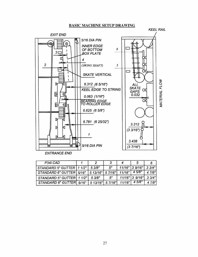
27
BASIC MACHINE SETUP DRAWING
28
SECTION: 17 GUTTER TALK
Common terms describing the condition of the gutter:
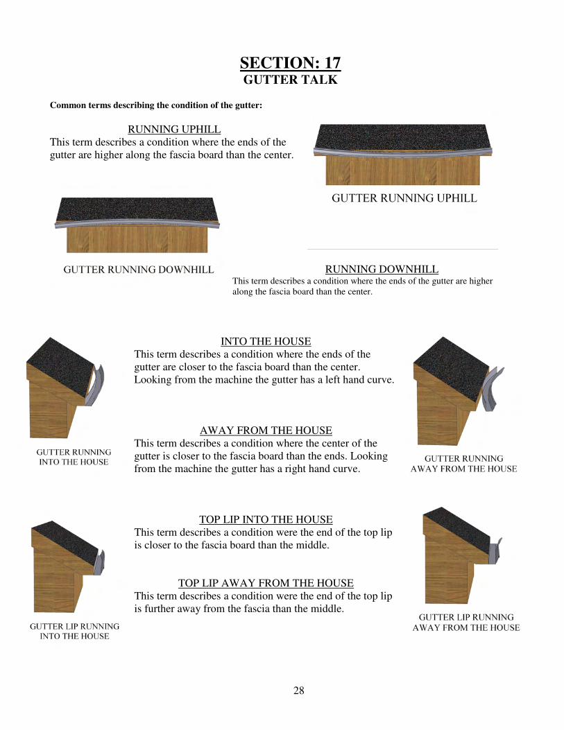
RUNNING UPHILL
This term describes a condition where the ends of the
gutter are higher along the fascia board than the center.
RUNNING DOWNHILL This term describes a condition where the ends of the gutter are higher
along the fascia board than the center.
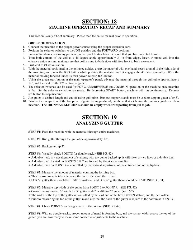
INTO THE HOUSE
This term describes a condition where the ends of the
gutter are closer to the fascia board than the center.
Looking from the machine the gutter has a left hand curve.
AWAY FROM THE HOUSE
This term describes a condition where the center of the
gutter is closer to the fascia board than the ends. Looking
from the machine the gutter has a right hand curve.
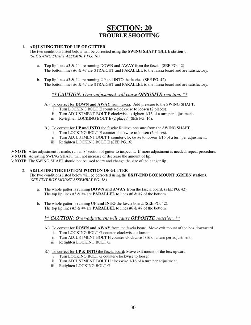
TOP LIP INTO THE HOUSE
This term describes a condition were the end of the top lip
is closer to the fascia board than the middle.
TOP LIP AWAY FROM THE HOUSE
This term describes a condition were the end of the top lip
is further away from the fascia than the middle.
29
SECTION: 18 MACHINE OPERATION RECAP AND SUMMARY
This section is only a brief summary. Please read the entire manual prior to operation.
ORDER OF OPERATION:
1. Connect the machine to the proper power source using the proper extension cord.
2. Position the selector switches to the JOG position and the FORWARD position.
3. Loosen thumbnuts, removing pressure on the spool brakes from the spool that you have selected to run.
4. Trim both corners of the coil at a 45-degree angle approximately 3” in from edges. Insert trimmed coil into the
entrance guide system, making sure that coil is snug to both sides with free front to back movement.
5. Push coil to #1 drive station.
6. With the material positioned in the entrance guides, grasp the material with one hand, reach around to the right side of
the machine, and press the JOG button while pushing the material until it engages the #1 drive assembly. With the
material moving forward under its own power, release JOG button.
7. Using the green start button at the main operator’s panel, advance the material through the guillotine approximately
12”, and then cut off the 12” section of gutter.
8. The selector switches can be used for FORWARD/REVERSE and JOG/RUN operation of the machine once machine
is fed. Set the selector switch to run mode. By depressing START button, machine will run continuously. Depress
red button to stop machine.
9. Jog gutter to desired length and cut off using guillotine. Run out support stands must be used to support gutter after 8’.
10. Prior to the completion of the last piece of gutter being produced, cut the coil stock before the entrance guides to clear
machine. The IRONMAN MACHINE should be empty when transporting from job to job.
SECTION: 19 ANALYZING GUTTER
STEP #1: Feed the machine with the material (through entire machine).
STEP #2: Run gutter through the guillotine approximately 12”.
STEP #3: Back gutter up 3”.
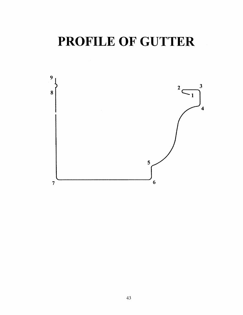
STEP #4: Visually check POINTS for double track. (SEE PG. 42)
• A double track is a misalignment of stations; with the gutter backed up, it will show as two lines or a double line.
• A double track located on POINTS 6 & 7 are formed by the skate assemblies.
• A double track on POINT 4 is controlled by the vertical adjustment of the entrance end of the lip box.
STEP #5: Measure the amount of material entering the forming box.
• This measurement is taken between the face rollers and the lip box.
• FOR 5” gutter there should be 1 3/8” of material, and FOR 6” gutter there should be 1 5/8” (SEE PG. 31).
STEP #6: Measure top width of the gutter from POINT 3 to POINT 9. (SEE PG. 42)
• Correct measurement: 5” width for 5” gutter and 6” width for 6” gutter (+/- 1/8”).
• The width of the top of the gutter is controlled by the exit end of the box, GREEN station, and the bell rollers
• Prior to measuring the top of the gutter, make sure that the back of the gutter is square to the bottom at POINT 7.
STEP #7: Check POINT 5 for being square to the bottom. (SEE PG. 42)
STEP #8: With no double tracks, proper amount of metal in forming box, and the correct width across the top of the
gutter, you are now ready to make some corrective adjustments to the machine.
30
SECTION: 20 TROUBLE SHOOTING
1. ADJUSTING THE TOP LIP OF GUTTER
The two conditions listed below will be corrected using the SWING SHAFT (BLUE station).
(SEE SWING SHAFT ASSEMBLY PG. 16)
a. Top lip lines #3 & #4 are running DOWN and AWAY from the fascia. (SEE PG. 42)
The bottom lines #6 & #7 are STRAIGHT and PARALLEL to the fascia board and are satisfactory.
b. Top lip lines #3 & #4 are running UP and INTO the fascia. (SEE PG. 42)
The bottom lines #6 & #7 are STRAIGHT and PARALLEL to the fascia board and are satisfactory.
** CAUTION: Over-adjustment will cause OPPOSITE reaction. **
A.) To correct for DOWN and AWAY from fascia: Add pressure to the SWING SHAFT.
i. Turn LOCKING BOLT E counter-clockwise to loosen (2 places).
ii. Turn ADJUSTMENT BOLT F clockwise to tighten 1/16 of a turn per adjustment.
iii. Re-tighten LOCKING BOLT E (2 places) (SEE PG. 16).
B.) To correct for UP and INTO the fascia: Relieve pressure from the SWING SHAFT.
i. Turn LOCKING BOLT E counter-clockwise to loosen (2 places).
ii. Turn ADJUSTMENT BOLT F counter-clockwise to loosen 1/16 of a turn per adjustment.
iii. Retighten LOCKING BOLT E (SEE PG.16).
� NOTE: After adjustment is made, run an 8’ section of gutter to inspect it. If more adjustment is needed, repeat procedure.
� NOTE: Adjusting SWING SHAFT will not increase or decrease the amount of lip.
� NOTE: The SWING SHAFT should not be used to try and change the size of the hanger lip.
2. ADJUSTING THE BOTTOM PORTION OF GUTTER The two conditions listed below will be corrected using the EXIT-END BOX MOUNT (GREEN station).
(SEE EXIT BOX MOUNT ASSEMBLY PG. 18)
a. The whole gutter is running DOWN and AWAY from the fascia board. (SEE PG. 42)
The top lip lines #3 & #4 are PARALLEL to lines #6 & #7 of the bottom.
b. The whole gutter is running UP and INTO the fascia board. (SEE PG. 42).
The top lip lines #3 & #4 are PARALLEL to lines #6 & #7 of the bottom.
** CAUTION: Over-adjustment will cause OPPOSITE reaction. **
A.) To correct for DOWN and AWAY from the fascia board: Move exit mount of the box downward.
i. Turn LOCKING BOLT G counter-clockwise to loosen.
ii. Turn ADJUSTMENT BOLT H counter-clockwise 1/16 of a turn per adjustment.
iii. Retighten LOCKING BOLT G.
B.) To correct for UP & INTO the fascia board: Move exit mount of the box upward.
i. Turn LOCKING BOLT G counter-clockwise to loosen.
ii. Turn ADJUSTMENT BOLT H clockwise 1/16 of a turn per adjustment.
iii. Retighten LOCKING BOLT G.
31
� Use #3 DRIVE FORMING ROLLER and SWING SHAFT ASSEMBLY as a
secondary option to acquire the same results. (SEE PG. 20)
� NOTE: Loosen LOCKING BOLT K prior to adjusting the top #3 DRIVE FORMING ASSEMBLY.
** CAUTION: Over-adjustment will cause OPPOSITE reaction. **
A.) To correct for DOWN and AWAY from the fascia board:
Add pressure to the face side of the top #3 DRIVE FORMING ROLLER.
i. Turn locknut on ADJUSTMENT BOLT I counter-clockwise to loosen.
ii. Turn ADJUSTMENT BOLT I clockwise 1/64 of a turn.
iii. Add pressure to the SWING SHAFT (BLUE station).
iv. Turn LOCKING BOLT E (2 places) counter-clockwise to loosen.
v. Turn ADJUSTMENT BOLT F clockwise 1/64 of a turn.
vi. Retighten all locking bolts/nuts.
B.) To correct for UP and INTO the fascia board:
Relieve pressure from the face side of the top #3 DRIVE FORMING ROLLER.
i. Turn locknut on ADJUSTMENT BOLT I counter-clockwise to loosen.
ii. Turn ADJUSTMENT BOLT I counter-clockwise 1/64 of a turn.
iii. Relieve pressure to the SWING SHAFT (BLUE station).
iv. Turn LOCKING BOLTS E clockwise to loosen.
v. Turn ADJUSTMENT BOLT F counter-clockwise 1/64 of a turn.
vi. Retighten all locking bolts/nuts.
� NOTE: After adjustment is made, run an 8’ section of gutter to inspect.
If more adjustment is needed, repeat procedure.
3. ADJUSTING THE WIDTH OF THE GUTTER If gutter is too wide or narrow between lines #3 and #9: (SEE PG. 42)
1. Check lines #6 & #7 for being at a 90-degree angle to the bottom. (SEE PG. 21)
A.) If less than a 90-degree angle is present: Add pressure to bell wheel.
i. Turn LOCKING BOLT A and PIVOT BOLT B counter-clockwise to loosen.
ii. Turn ADJUSTMENT BOLT B clockwise a 1/16 of a turn.
B.) If more than a 90-degree angle is present: Relieve pressure to bell wheel.
i. Turn LOCKING BOLT A and PIVOT BOLT B counter-clockwise to loosen.
ii. Turning ADJUSTMENT BOLT B counter-clockwise a 1/16 of a turn.
2. If #6 and #7 are square to the bottom and the gutter is too wide or narrow. (SEE PG. 18)
A.) If gutter is too wide: Move EXIT BOX MOUNT towards the back of gutter.
i. Loosen MOUNTING BOLTS (K)
ii. Loosen LOCKING NUT (L-2)
iii. Turn ADJUSTMENT BOLT (M-2) clockwise 1/16 of a turn.
iv. Tighten MOUNTING BOLTS (K) and LOCKING NUT (L-2)
B.) If gutter is too narrow: Move EXIT BOX MOUNT away from the back of gutter.
i. Loosen MOUNTING BOLTS (K)
ii. Loosen LOCKING NUT (L-1)
iii. Turn ADJUSTMENT BOLT (M-1) clockwise 1/16 of a turn.
iv. Tighten MOUNTING BOLTS (K) and LOCKING NUT (L-1)
� NOTE: After adjustment is made, run an 8’ section of gutter to inspect.
If more adjustment is needed, repeat procedure.
32
4. CONTINUOUS MARKS OR SCRATCHES
a. Check for interference with shear.
b. Inspect guide rods for imperfections.
5. MATERIAL SLIPPING: (MACHINE NOT PULLING MATERIAL THROUGH)
a. Check the pressure on the spool shaft that is in use from the upright brakes.
b. Check that the entrance guides are not too tight or restricting the material.
i. If the guides are correct and the spools are unlocked, add pressure to the #1 & #2 drive assemblies
(SEE PG. 14, SECTION 10).
ii. When metal slippage occurs while clearing machine and after metal is past the #2 drive, add equal
pressure to the #3 DRIVE FORMING ROLLER (SEE PG. 19).
6. OIL CANNING OR RIPPLING ON BOTTOM
a. An imperfect bottom on the gutter is very uncommon from the IRONMAN.
i. Check all bottom rollers, drive rollers, and skate rollers for tape, debris, or buildup.
ii. Make sure top drive rollers are not past factory tolerance.
33
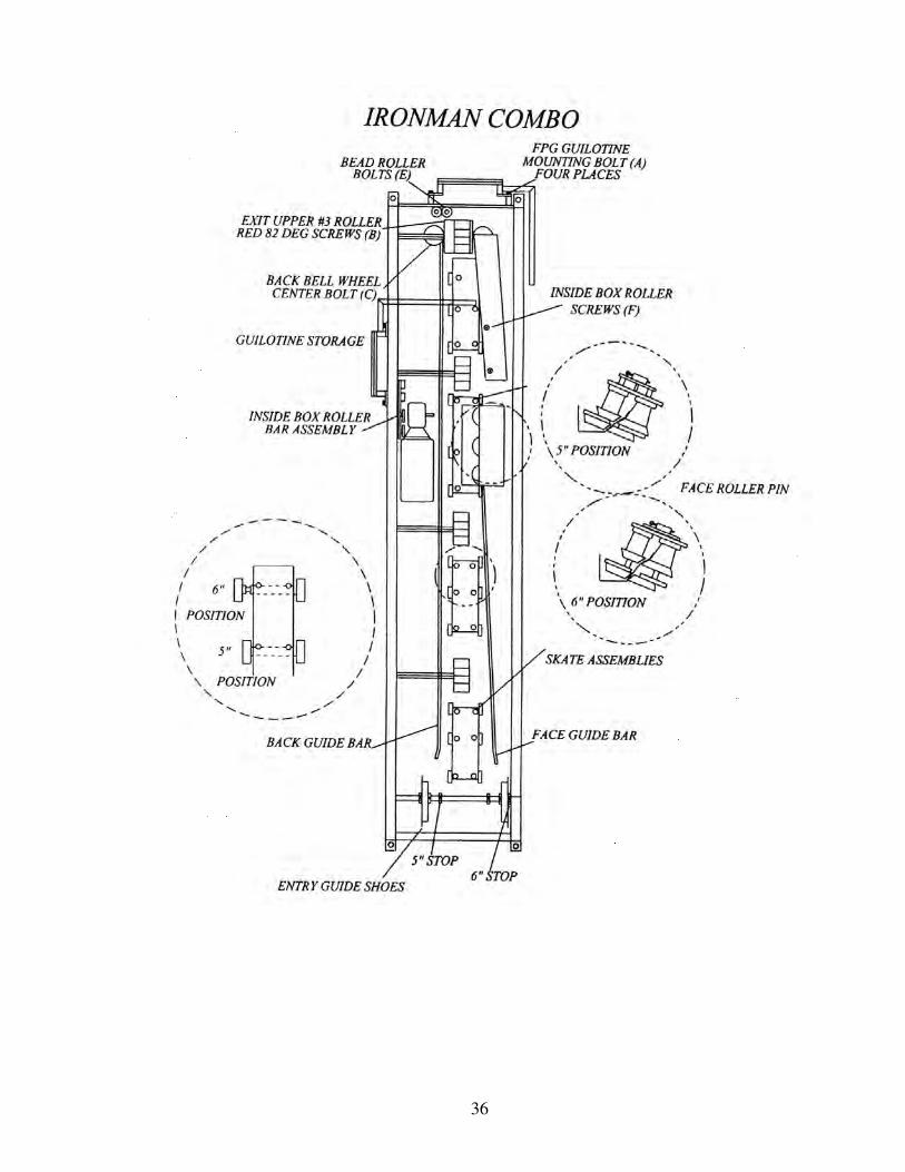
SECTION: 22 COMBO CONVERSION INSTRUCTIONS
• The process to change from the 5” gutter profile to the 6” gutter profile and then back again is considerably simplified by
using retractable pins with two secured positions that provide an easy change.
• A tool kit is provided with every combo machine and is located inside the left-side cover at the exit end of the machine.
• When converting from one profile to the other, it is important to follow the instructions in the correct order for efficiency.
• The order to convert 5” to 6” is NOT the same as for 6” to 5”, so follow the instructions carefully.
5” to 6” CONVERSION � CAUTION: Make sure that the machine has been disconnected from the power source before starting conversion.
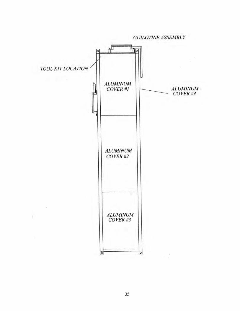
STEP 1: REMOVE ALUMINUM COVERS #1-4. (SEE PG. 34 for lid details and for tool kit location).
• To remove aluminum lids #1-4, use flat-head screwdriver to turn screws counter-clockwise ¼ turn.
STEP 2: REMOVE 5” GUILLOTINE AND SET ASIDE. (SEE PG. 35 for guillotine location).
• To remove guillotine, unscrew the four mounting bolts (E). (SEE SECTION 15, PG. 22-23).
STEP 3: MOVE BEAD ASSEMBLY TO 6” POSITION. (SEE PG. 37)
• Loosen the two locking bolts.
• Slide the bead assembly up for the 6” position. (positions are marked)
• Tighten the locking bolts.
STEP 4: REMOVE BACK BELL ROLLER AND SET ASIDE. (SEE 37)
• To remove back bell roller, unscrew the back bell wheel bolt (W) that holds the center shaft in place.
STEP 5: MOVE BACK GUIDE BAR TO 6” POSITION. (SEE PG. 35)
• Loosen the five bolts on the back guide bar.
• Move it as far away from the skate as possible.
• Tighten the five bolts.
STEP 6: FLIP TOP #3 DRIVE BACKSIDE ROLLER. (SEE PG. 37)
• To flip the top #3 drive backside roller, remove the RED station (B) ¼ -20 x ½” flush head cap screws located in
the center of the roller.
• Turn the roller end-for-end and replace it back onto the shaft by aligning the threaded holes in the shaft with the
clearance holes on the exit upper #3 top roller backside.
• Failure to align the roller properly will cause damage.
STEP 7: INSTALL THE BACK BELL ROLLER. (SEE PG. 37)
• Install the back bell roller in the 6” position labeled. (positions are marked)
STEP 8: INSTALL 6” GUILLOTINE. (SEE PG. 23-24)
• Remove the 6” guillotine from the side of the machine. (SEE PG. 35)
• Install it onto the frame, using the mounting bolts removed in step 1.
• The guillotine is factory preset and should not need adjustment.
STEP 9: STORE 5” GUILLOTINE. (SEE PG. 35)
• Store the 5” guillotine on the side of the machine.
STEP 10: MOVE THE 13 SKATE ROLLERS ON THE FOUR CENTER SKATES. (SEE PG. 36)
• To change, pull the retractable pin up at each skate until the pin disengages from the adjustable skate shaft.
• Slide the forming roller to the 6” position and release pin.
• Repeat this process for all thirteen rear skate-forming rollers.
34
STEP 11: MOVE ENTRY GUIDE SHOES. (SEE PG. 36)
• There are two split collars used as stops on the entrance guide shaft to locate each entrance guide shoe for the
5” and 6” gutter position.
• To position the entrance guide shoes from the 5” to the 6” position, loosen cap screws and slide the entrance
guide shoes against the outer most collars on the shaft.
STEP 12: MOVE THE THREE FACE BOX ASSEMBLY STATIONS. (SEE PG. 37)
• Pull the retractable pin that is located at the top of each station assembly.
• Raise the face roller assembly up to the 6” gutter position and release pin.
• Repeat this step for each of the face box assemblies.
STEP 13: MOVE LIP BOX ASSEMBLY. (SEE PG. 37)
• Loosen the two MOUNTING BOLTS on the ENTRANCE MOUNT ASSEMBLY. (BLACK)
• Loosen the two MOUNTING BOLTS on the EXIT MOUNTING ASSEMBLY. (GREEN)
• Move the lip box up and out on the box frame mounts.
• Tighten mounting bolts.
STEP 14: REMOVE THE 5” INSIDE BOX ROLLER BAR ASSEMBLY. (SEE PG. 35)
• To remove the 5” inside box roller bar assembly, remove the two RED station F-screws on the top of the box.
• Place this assembly to the side.
STEP 15: MOVE THE SIX OUTSIDE BOX BOTTOM ROLLERS. (SEE PG. 37)
• Pull the retractable pin and lower the bottom portion of the outside roller down to the 6” position.
• Release the retractable pin.
• Repeat this step for each of the lip box stations.
STEP 16: INSTALL THE 6” INSIDE BOX ROLLER BAR ASSEMBLY. (SEE PG. 37)
• Remove the 6” inside box roller bar assembly from the storage location; this assembly is labeled as (6).
• Install the 6” inside box roller bar assembly in the lip box, replace the two RED station F-SCREWS and tighten.
• The tall rollers located in the #1 station and the #2 station.
The short rollers located in the #3 station and the #4 station.
STEP 17: STORE 5” INSIDE BOX ROLLER BAR ASSEMBLY. (SEE PG. 35)
• Install the 5” inside box roller bar assembly from the storage location
STEP 18: REPLACE #1-4 COVERS. (SEE PG. 34)
• Turn the cover screws ¼ turn clockwise to fasten.
STEP 19: MOVE UPRIGHT BASE-PLATE. (SEE PG. 10)
• Remove Coil Spool from Upright Assembly
• Rotate the upright to access the two bolts on the face side.
• Loosen the four L-SCREWS as shown.
• Slide the upright base-plate to the 6” position.
• Tighten the screws.
STEP 20: REPLACE THE 5” SPOOL ASSEMBLY WITH 6” SPOOL ASSEMBLY. (SEE PG. 10)
• Remove the 5” spool assembly
• Load the 6” gutter material on Spool Assembly. (SEE SECTION 8, PG. 9)
• Place loaded spool onto upright assembly using an approved lifting device.
• NOTE: Pins must be reinstalled in holes stamped for the 6” position.
� CAUTION: Spool must line up with the entrance guides.
35
36
37
38
39
6” to 5” CONVERSION � CAUTION: Make sure that the machine has been disconnected from the power source before starting conversion.
• The order to convert 6” to 5” is NOT the same as for 5” to 6”, so follow the instructions carefully.
STEP 1: REMOVE ALUMINUM COVERS #1-4. (SEE PG. 34 for lid details and for tool kit location).
• To remove aluminum lids #1-4, use flat-head screwdriver to turn screws counter-clockwise ¼ turn.
STEP 2: REMOVE 6” GUILLOTINE AND SET ASIDE. (SEE PG. 35 for guillotine location).
• To remove guillotine, unscrew the four mounting bolts (E). (SEE SECTION 15, PG. 23-24).
STEP 3: REMOVE BACK BELL ROLLER AND SET ASIDE. (SEE PG. 35)
• To remove back bell roller, unscrew the back bell wheel bolt (W) that holds the center shaft in place.
STEP 4: FLIP TOP #3 DRIVE BACKSIDE ROLLER. (SEE PG, 37)
• To flip the top #3 drive backside roller, remove the RED station (B) ¼ -20 x ½” flush head cap screws located in
the center of the roller.
• Turn the roller end-for-end and replace it back onto the shaft by aligning the threaded holes in the shaft with the
clearance holes on the exit upper #3 top roller backside.
• Failure to align the roller properly will cause damage.
STEP 5: INSTALL THE BACK BELL ROLLER. (SEE PG. 37)
• Install the back bell roller in the 5” position labeled. (Positions are marked)
STEP 6: MOVE BEAD ASSEMBLY TO 5” POSITION. (SEE PG. 37)
• Loosen the two locking bolts.
• Slide the bead assembly up for the 5” position. (Positions are marked)
• Tighten the locking bolts.
STEP 7: INSTALL 5” GUILLOTINE. (SEE PG. 23-24)
• Remove the 5” guillotine from the side of the machine. (SEE PG. 35)
• Install it onto the frame, using the mounting bolts removed in step 1.
• The guillotine is factory preset and should not need adjustment.
STEP 8: STORE 6” GUILLOTINE. (SEE PG. 35)
• Store the 6” guillotine on the side of the machine.
STEP 9: MOVE THE 13 SKATE ROLLERS ON THE FOUR CENTER SKATES. (SEE PG. 36)
• To change, pull the retractable pin up at each skate until the pin disengages from the adjustable skate shaft.
• Slide the forming roller to the 5” position and release pin.
• Repeat this process for all thirteen rear skate-forming rollers.
STEP 10: MOVE BACK GUIDE BAR TO 5” POSITION. (SEE PG. 35)
• Loosen the five bolts on the back guide bar.
• Move it as close to the skate as possible.
• Tighten the five bolts.
STEP 11: MOVE ENTRY GUIDE SHOES. (SEE PG. 36)
• There are two split collars used as stops on the entrance guide shaft to locate each entrance guide shoe for the 5”
and 6” gutter position.
• To move the entrance guide shoes from the 6” to the 5” position, loosen the cap screws and slide the entrance
guide shoes against the inner most collars on the shaft.
40
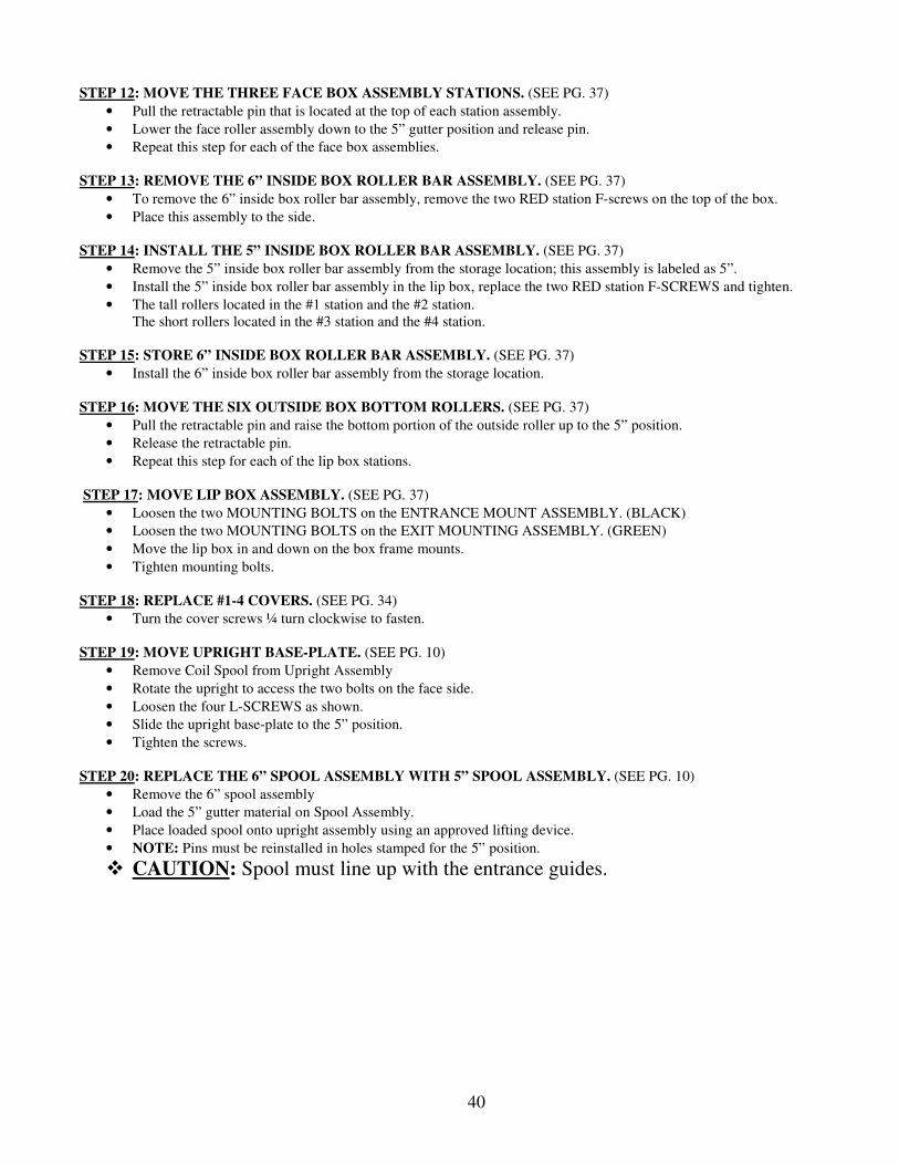
STEP 12: MOVE THE THREE FACE BOX ASSEMBLY STATIONS. (SEE PG. 37)
• Pull the retractable pin that is located at the top of each station assembly.
• Lower the face roller assembly down to the 5” gutter position and release pin.
• Repeat this step for each of the face box assemblies.
STEP 13: REMOVE THE 6” INSIDE BOX ROLLER BAR ASSEMBLY. (SEE PG. 37)
• To remove the 6” inside box roller bar assembly, remove the two RED station F-screws on the top of the box.
• Place this assembly to the side.
STEP 14: INSTALL THE 5” INSIDE BOX ROLLER BAR ASSEMBLY. (SEE PG. 37)
• Remove the 5” inside box roller bar assembly from the storage location; this assembly is labeled as 5”.
• Install the 5” inside box roller bar assembly in the lip box, replace the two RED station F-SCREWS and tighten.
• The tall rollers located in the #1 station and the #2 station.
The short rollers located in the #3 station and the #4 station.
STEP 15: STORE 6” INSIDE BOX ROLLER BAR ASSEMBLY. (SEE PG. 37)
• Install the 6” inside box roller bar assembly from the storage location.
STEP 16: MOVE THE SIX OUTSIDE BOX BOTTOM ROLLERS. (SEE PG. 37)
• Pull the retractable pin and raise the bottom portion of the outside roller up to the 5” position.
• Release the retractable pin.
• Repeat this step for each of the lip box stations.
STEP 17: MOVE LIP BOX ASSEMBLY. (SEE PG. 37)
• Loosen the two MOUNTING BOLTS on the ENTRANCE MOUNT ASSEMBLY. (BLACK)
• Loosen the two MOUNTING BOLTS on the EXIT MOUNTING ASSEMBLY. (GREEN)
• Move the lip box in and down on the box frame mounts.
• Tighten mounting bolts.
STEP 18: REPLACE #1-4 COVERS. (SEE PG. 34)
• Turn the cover screws ¼ turn clockwise to fasten.
STEP 19: MOVE UPRIGHT BASE-PLATE. (SEE PG. 10)
• Remove Coil Spool from Upright Assembly
• Rotate the upright to access the two bolts on the face side.
• Loosen the four L-SCREWS as shown.
• Slide the upright base-plate to the 5” position.
• Tighten the screws.
STEP 20: REPLACE THE 6” SPOOL ASSEMBLY WITH 5” SPOOL ASSEMBLY. (SEE PG. 10)
• Remove the 6” spool assembly
• Load the 5” gutter material on Spool Assembly.
• Place loaded spool onto upright assembly using an approved lifting device.
• NOTE: Pins must be reinstalled in holes stamped for the 5” position.
� CAUTION: Spool must line up with the entrance guides.

41
SECTION: 23 5” to 6” COMBO CHANGE OVER CHECK LIST
1. ___ UNPLUG MACHINE:
Eliminate electrical power source.
2. ___ REMOVE COVERS:
Remove covers containing quick-release fasteners.
3. ___ REMOVE GUILLOTINE:
Remove 5” guillotine from machine.
4. ___ MOVE BEAD ROLLER ASSEMBLY: Loosen and slide bead roller assembly into 6” position
5. ___ REMOVE BACK BELL ROLLER:
Remove from 5” position, and set it to the side.
6. ___ MOVE BACK GUIDE ROD:
Loosen guide rod bolts, and slide guide rod away from skate.
7. ___ FLIP TOP #3 EXIT DRIVE ROLLER: Remove & reinstall top #3 back drive roller in 6” position.
Turn roller end-for-end and reinstall using same 82-degree cap screws.
8. ___ INSTALL BACK BELL WHEEL: Install back bell wheel in the 6” position.
9. ___ INSTALL 6” GUILLOTINE: Install 6” guillotine on machine.
10. ___ SECURE 5” GUILLOTINE: Place the 5” guillotine back into storage position.
11. ___ MOVE SKATE ROLLERS: Pull retractable pins on skate rollers and move outward to 6” position.
12. ___ MOVE ENTRANCE GUIDES: Loosen cap screw on both entrance guides, and move outward to stop at 6” position.
13. ___ MOVE FACE BOX ROLLERS: Pull retractable pins and raise face box rollers to 6” position.
14. ___ MOVE COMPLETE LIP BOX: Loosen mounting bolts and move lip box to 6” position.
15. ___ REMOVE 5” INSIDE ROLLER BAR FROM LIP BOX: Remove red colored screws, remove roller bar and set to the side.
16. ___ MOVE LIP BOX BOTTOM ROLLERS: Pull retractable pins and lower bottom half of the outside lip box roller to 6” position.
17. ___ INSTALL 6” INSIDE ROLLER BAR ASSEMBLY. Remove 6” roller bar from storage position and install in lip box.
18. ___ STORE 5” INSIDE ROLLER BAR: Secure 5” inside roller bar in storage position.
19. ___ REINSTALL COVERS:
Refasten covers and lids to machine.
20. ___ MOVE COIL SPOOL HALVES: Position spool halves for 15” coil.
21. ___ MOVE UPRIGHT ASSEMBLY: Move upright assembly to the 6” Position.
42
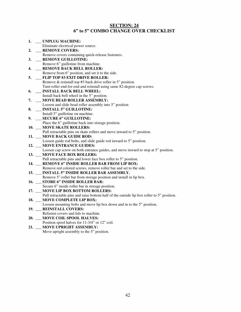
SECTION: 24
6” to 5” COMBO CHANGE OVER CHECKLIST
1. ___ UNPLUG MACHINE:
Eliminate electrical power source.
2. ___ REMOVE COVERS: Remove covers containing quick-release fasteners.
3. ___ REMOVE GUILLOTINE:
Remove 6” guillotine from machine.
4. ___ REMOVE BACK BELL ROLLER:
Remove from 6” position, and set it to the side.
5. ___ FLIP TOP #3 EXIT DRIVE ROLLER: Remove & reinstall top #3 back drive roller in 5” position.
Turn roller end-for-end and reinstall using same 82-degree cap screws.
6. ___ INSTALL BACK BELL WHEEL:
Install back bell wheel in the 5” position.
7. ___ MOVE BEAD ROLLER ASSEMBLY:
Loosen and slide bead roller assembly into 5” position
8. ___ INSTALL 5” GUILLOTINE: Install 5” guillotine on machine.
9. ___ SECURE 6” GUILLOTINE: Place the 6” guillotine back into storage position.
10. ___ MOVE SKATE ROLLERS: Pull retractable pins on skate rollers and move inward to 5” position.
11. ___ MOVE BACK GUIDE ROD: Loosen guide rod bolts, and slide guide rod inward to 5” position.
12. ___ MOVE ENTRANCE GUIDES: Loosen cap screw on both entrance guides, and move inward to stop at 5” position.
13. ___ MOVE FACE BOX ROLLERS: Pull retractable pins and lower face box roller to 5” position.
14. ___ REMOVE 6” INSIDE ROLLER BAR FROM LIP BOX: Remove red colored screws, remove roller bar and set to the side.
15. ___ INSTALL 5” INSIDE ROLLER BAR ASSEMBLY. Remove 5” roller bar from storage position and install in lip box.
16. ___ STORE 6” INSIDE ROLLER BAR: Secure 6” inside roller bar in storage position.
17. ___ MOVE LIP BOX BOTTOM ROLLERS: Pull retractable pins and raise bottom half of the outside lip box roller to 5” position.
18. ___ MOVE COMPLETE LIP BOX:
Loosen mounting bolts and move lip box down and in to the 5” position.
19. ___ REINSTALL COVERS: Refasten covers and lids to machine.
20. ___ MOVE COIL SPOOL HALVES: Position spool halves for 11-3/4” or 12” coil.
21. ___ MOVE UPRIGHT ASSEMBLY:
Move upright assembly to the 5” position.
43
44
WARRANTY INFORMATION
KWM GUTTERMAN, INC. warrants the machine described in your invoice. KWM GUTTERMAN, INC.
will replace or repair any part(s) of the machine that are defective in workmanship or material for a period of
24 months from the date of purchase. Claims under this warranty are the sole option of the manufacturer.
The obligation under this warranty is limited to the replacement or repair of such parts defective in material or
workmanship. This warranty does not cover failures found to have been caused by wear, damage, abuse,
misuse, accident or any procedures contrary to instructions set forth in the instruction manual. This warranty
does not obligate KWM GUTTERMAN, INC. to bear the cost of the materials used for adjustment or
transportation charges in connection with the replacement or repair of defective parts nor shall it apply to a
machine upon which repairs or alterations have been made unless authorized by KWM GUTTERMAN, INC.
KWM GUTTERMAN, INC. shall, in no event, be liable for consequential damage or contingent liabilities
arising out of the failure of any machine or parts to operate properly.
KWM GUTTERMAN, INC. shall, in no event, be liable to bear costs of lost work, material, travel, or freight,
caused by any part(s) of the machine that are defective in workmanship or material. All warranty work must
be returned to 795 S. Larkin Avenue, Rockdale, Illinois. Prior authorization must be obtained from KWM
GUTTERMAN, INC. before any warranty work will be performed.
THE WARRANTIES SET FORTH HEREIN ARE IN LIEU OF ALL OTHER WARRANTIES
EXPRESSED OR IMPLIED. THE BUYER ACKNOWLEDGES THAT NO OTHER REPRESENTATIONS
WERE MADE TO HIM OR RELIED UPON BY HIM WITH RESPECT TO THE QUALITY AND
FUNCTIONS OF THE MACHINE.

45