Embed Size (px)
Citation preview
2
Table of Contents
Command SeriesGeneral
.............................................................................................................................5Command Twin
............................................................................................................................5 .............................................................................................................................6
..............................................................................................................................................6 ....................................................................................................................
.............................................................................................................. ....................................................................................................
...........................................................................................................EFI
.....................................................................................................................Command Single
.................................................................................................................................................
Aegis Series ............................................................................................................................................
..................................................................................................................................................
Courage SeriesGeneral
...............................................................................................................Courage Twin
.......................................................................................................................................... ............................................................................................................................................
Courage Single ..............................................................................................................................
.......................................................................................................................................... ................................................................................................................................................
................................................................................................................... ........................................................................................
Courage XT ...........................................................................................................................................
.....................................................................................................................................
Kohler DieselGeneral
..................................................................................................................... .......................................................................................................................................
All Air-Cooled Series ..............................................................................................................................................20
15LD 400/KD400...................................................................................................20
15LD 315-440/KD315-440 ...............................................................................................................................
.................................................................................................................All Liquid-Cooled Series
..............................................................................................................................22 ..........................................................................................................................22
LDW 702-1404/KDW702-1404 .......................................................................................................23
..........................................23 .................................................................................................................................................
............................................................
3
Command Series
LDW 702-1404/KDW702-1404 (cont.) Control Panel Indicator Lights.............................................................................................................................25 Key/Key Switch Change .....................................................................................................................................26
New ProductKohler Introduces New Command PRO Horizontal Engine Line........................................................................ 27-29Kohler Enters Consumer Horizontal Market ....................................................................................................... 30-31New Commercial EFI................................................................................................................................................32Courage XT-6 ...........................................................................................................................................................33
MiscellaneousReplace Mating Gears..............................................................................................................................................35Erratic Running & Vapor Lock ..................................................................................................................................35Bearing Concern.......................................................................................................................................................35Makes You Think... ...................................................................................................................................................36Ditch Witch Dipstick..................................................................................................................................................36Who Left the Oil Lights On .......................................................................................................................................37New/Reinstated Service Tools..................................................................................................................................37Bearing Failures .......................................................................................................................................................38Anti-Icing Components .............................................................................................................................................39Replacement Engine Reminder................................................................................................................................40Troubleshooting Electric Starters ....................................................................................................................... 41-43Kohler PLUS News............................................................................................................................................. 44-46Factory School Invite .......................................................................................................................................... 47-48
Warranty NewsWarranty System NOW AVAILABLE................................................................................................................... 49-51Helpful System Tips..................................................................................................................................................52EWR Review (Engine Warranty Return) ............................................................................................................ 53-54
Bulletins, Etc.Parts Bulletins New EFI Long Block for Walker CH26 (PB-251) ................................................................................................56 Correct Fuel Filter Selection (PB-253)................................................................................................................57 Short Blocks for Courage Single Cylinder Engines (PB-254) .............................................................................58Service Bulletins Loose/Cracked Flywheel Ring Gears (SB-285)..................................................................................................59
...........................................................................................60 Flywheel and Mounting Stud Replacement (SB-288)................................................................................... 61-64 Flywheel Timing Change (SB-289) ............................................................................................................... 65-66 Oil Pressure Switch 25 099 27-S (SB-290) ........................................................................................................67 DSAI Interface Wire Harnesses with Diodes (SB-291).......................................................................................68Technical Flashes Ground Relocation on Dixon ZTR Mowers .........................................................................................................69 Engines Stalling with Fuel in Tank ......................................................................................................................70 XT-7 Fuel Tank Outlet Flash Removal ................................................................................................................71 Courage XT-7 Flywheel Brake Ignition Grounding Issue....................................................................................72TechTips Electronic Governor - Overview, Diagnosing, and Troubleshooting (2008-02)............................................. 73-80 Electronic Governor - Overview, Diagnosing, and Troubleshooting (2008-01)............................................. 81-88 Kohler Engines Truck-Mounted Applications Grounding Instructions (2007-01) ................................................89
4
Command Series
Technician’s Service TestGasoline ............................................................................................................................................................. 92-95Diesel........................................................................................................................................................................96Tear-Out Answer Sheet ............................................................................................................................................97
5
Command Series
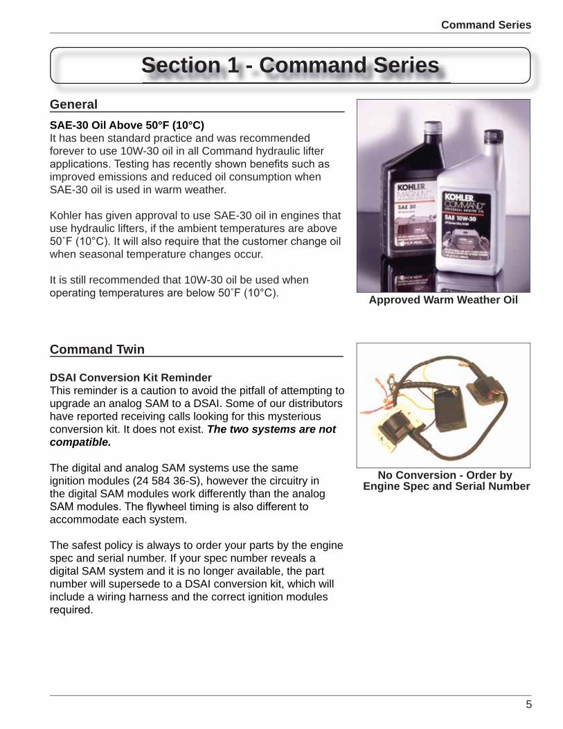
Section 1 - Command SeriesGeneralSAE-30 Oil Above 50°F (10°C)It has been standard practice and was recommendedforever to use 10W-30 oil in all Command hydraulic lifter
improved emissions and reduced oil consumption whenSAE-30 oil is used in warm weather.
Kohler has given approval to use SAE-30 oil in engines thatuse hydraulic lifters, if the ambient temperatures are above
when seasonal temperature changes occur.
It is still recommended that 10W-30 oil be used when
Approved Warm Weather Oil
Command Twin
DSAI Conversion Kit ReminderThis reminder is a caution to avoid the pitfall of attempting toupgrade an analog SAM to a DSAI. Some of our distributorshave reported receiving calls looking for this mysteriousconversion kit. It does not exist. The two systems are not compatible.
The digital and analog SAM systems use the sameignition modules (24 584 36-S), however the circuitry inthe digital SAM modules work differently than the analog
accommodate each system.
The safest policy is always to order your parts by the enginespec and serial number. If your spec number reveals adigital SAM system and it is no longer available, the partnumber will supersede to a DSAI conversion kit, which willinclude a wiring harness and the correct ignition modules
No Conversion - Order by Engine Spec and Serial Number
6
Command Series
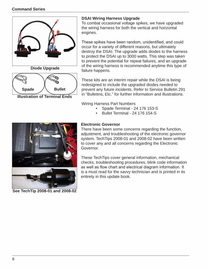
DSAI Wiring Harness UpgradeTo combat occasional voltage spikes, we have upgradedthe wiring harness for both the vertical and horizontalengines.
occur for a variety of different reasons, but ultimatelydestroy the DSAI. The upgrade adds diodes to the harnessto protect the DSAI up to 3000 watts. This step was takento prevent the potential for repeat failures, and an upgradeof the wiring harness is recommended anytime this type offailure happens.
These kits are an interim repair while the DSAI is beingredesigned to include the upgraded diodes needed toprevent any future incidents. Refer to Service Bulletin 291in “Bulletins, Etc.” for further information and illustrations.
Wiring Harness Part NumbersSpade Terminal - 24 176 153-SBullet Terminal - 24 176 154-S
••
Diode Upgrade
Electronic GovernorThere have been some concerns regarding the function,adjustment, and troubleshooting of the electronic governorsystem. TechTips 2008-01 and 2008-02 have been writtento cover any and all concerns regarding the ElectronicGovernor.
These TechTips cover general information, mechanicalchecks, troubleshooting procedures, blink code information
is a must read for the savvy technician and is printed in itsentirety in this update book.
See TechTip 2008-01 and 2008-02
Spade Bullet
Illustration of Terminal Ends
7
Command Series
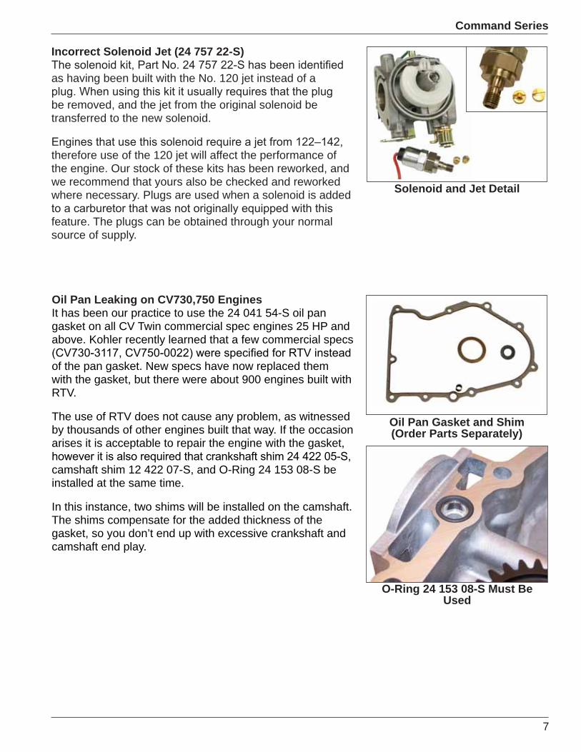
Incorrect Solenoid Jet (24 757 22-S)
as having been built with the No. 120 jet instead of a
be removed, and the jet from the original solenoid betransferred to the new solenoid.
therefore use of the 120 jet will affect the performance ofthe engine. Our stock of these kits has been reworked, andwe recommend that yours also be checked and reworkedwhere necessary. Plugs are used when a solenoid is added
feature. The plugs can be obtained through your normalsource of supply.
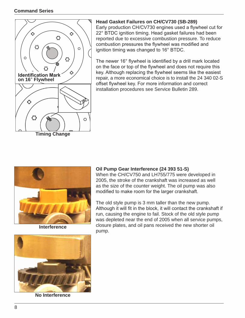
Oil Pan Gasket and Shim (Order Parts Separately)
Solenoid and Jet Detail
O-Ring 24 153 08-S Must Be Used
Oil Pan Leaking on CV730,750 EnginesIt has been our practice to use the 24 041 54-S oil pangasket on all CV Twin commercial spec engines 25 HP andabove. Kohler recently learned that a few commercial specs
of the pan gasket. New specs have now replaced themwith the gasket, but there were about 900 engines built withRTV.
The use of RTV does not cause any problem, as witnessedby thousands of other engines built that way. If the occasionarises it is acceptable to repair the engine with the gasket,
camshaft shim 12 422 07-S, and O-Ring 24 153 08-S beinstalled at the same time.
In this instance, two shims will be installed on the camshaft.The shims compensate for the added thickness of thegasket, so you don’t end up with excessive crankshaft andcamshaft end play.
8
Command Series
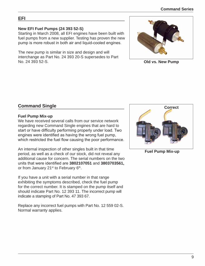
Oil Pump Gear Interference (24 393 51-S)When the CH/CV750 and LH755/775 were developed in2005, the stroke of the crankshaft was increased as wellas the size of the counter weight. The oil pump was also
The old style pump is 3 mm taller than the new pump.
run, causing the engine to fail. Stock of the old style pumpwas depleted near the end of 2005 when all service pumps,closure plates, and oil pans received the new shorter oilpump.
Interference
No Interference
Head Gasket Failures on CH/CV730 (SB-289)
reported due to excessive combustion pressure. To reduce
repair, a more economical choice is to install the 24 340 02-S
installation procedures see Service Bulletin 289.
Timing Change
on 16 Flywheel
9
Command Series
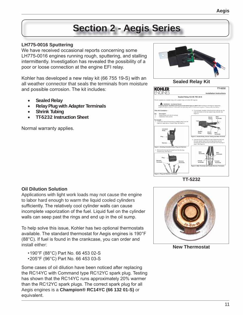
Old vs. New Pump
EFI
New EFI Fuel Pumps (24 393 52-S)Starting in March 2008, all EFI engines have been built withfuel pumps from a new supplier. Testing has proven the new
The new pump is similar in size and design and willinterchange as Part No. 24 393 20-S supersedes to PartNo. 24 393 52-S.
Command Single
Fuel Pump Mix-upWe have received several calls from our service networkregarding new Command Single engines that are hard to
An internal inspection of other singles built in that timeperiod, as well as a check of our stock, did not reveal anyadditional cause for concern. The serial numbers on the two
3802107051 and 3803703561,or from January 21st to February 6th.
If you have a unit with a serial number in that rangeexhibiting the symptoms described, check the fuel pumpfor the correct number. It is stamped on the pump itself andshould indicate Part No. 12 393 11. The incorrect pump willindicate a stamping of Part No. 47 393 67.
Replace any incorrect fuel pumps with Part No. 12 559 02-S.Normal warranty applies.
Fuel Pump Mix-up
Correct

10
Command Series
11
Aegis
Sealed Relay Kit
New Thermostat
Installation Instructions
TT-5232
Sealed Relay Kit 66 755 19-SThis kit replaces an unsealed relay with a sealed relay on Kohler EFI engines.
WARNING: Accidental Starts!Disabling engine. Accidental starting can cause severe injury or death. Before working on the engine or equipment,
This Kit Contains –
Qty. Description1 Sealed Relay (with shrink tubing)1 Installation Instructions
To Install –1. Locate and remove the existing unsealed relay from the
engine or application. Discard relay. See Figure 1.
Figure 1. Existing Unsealed Relay, Plug and Harness.
UnsealedRelay
Plug
Harness
2. Remove the harness terminals from the old plug. Discard plug. See Figure 2.
Figure 2. Plug and Harness Terminals.
Plug
HarnessTerminals
3. If not already installed, slide the shrink tubing over the male terminals on the new sealed relay harness. See Figure 3.
Figure 3. Sealed Relay, Shrink Tubing and Male Terminal.
SealedRelay
MaleTerminals
ShrinkTubing
ShrinkTubing
4. Connect the color-coded wire and male terminal from the new sealed relay to the corresponding colored harness and female terminal removed from the plug in step 2. See Figure 4.
Figure 4. Male Terminal and Female Harness Terminals.
FemaleTerminals
HarnessTerminals
FemaleTerminals
MaleTerminals
MaleTerminals
MaleTerminals
TT-5232
Section 2 - Aegis Series
Oil Dilution SolutionApplications with light work loads may not cause the engine to labor hard enough to warm the liquid cooled cylinders
install either:
Aegis engines is a Champion® RC14YC (66 132 01-S) or
LH775-0016 Sputtering
all weather connector that seals the terminals from moisture
Sealed RelayRelay Plug with Adapter TerminalsShrink TubingTT-5232 Instruction Sheet

Aegis
Cub Cadet Harness Protection and Vapor Lock
Models Affected:Volunteer™ 4X4 EFI (37AM46ED710)Volunteer™ 4X4 EFI (37AM465D710)Volunteer™ 4X4 EFI (37AM467D710)
Cub Serial Numbers Affected:
Cub Cadet Service Advisory
Volunteer 4X4 EFI Vehicle
13
Courage Series
Section 3 - Courage Series
Machined Cam
Courage Twin
Assembled Camshaft The new automotive style, “assembled camshaft” consists of a machined metal shaft, powdered metal lobes, and a nylon gear.
This design is not new technology, and is used by some of the most successful and well known automotive engine manufacturers in the world. It reduces the noise, weight, and cost of the cam without compromising the durability that Kohler Engines are known for.
helical cut crankshaft gears.
The cam will be introduced on the 2009 product line.
Assembled Cam
General
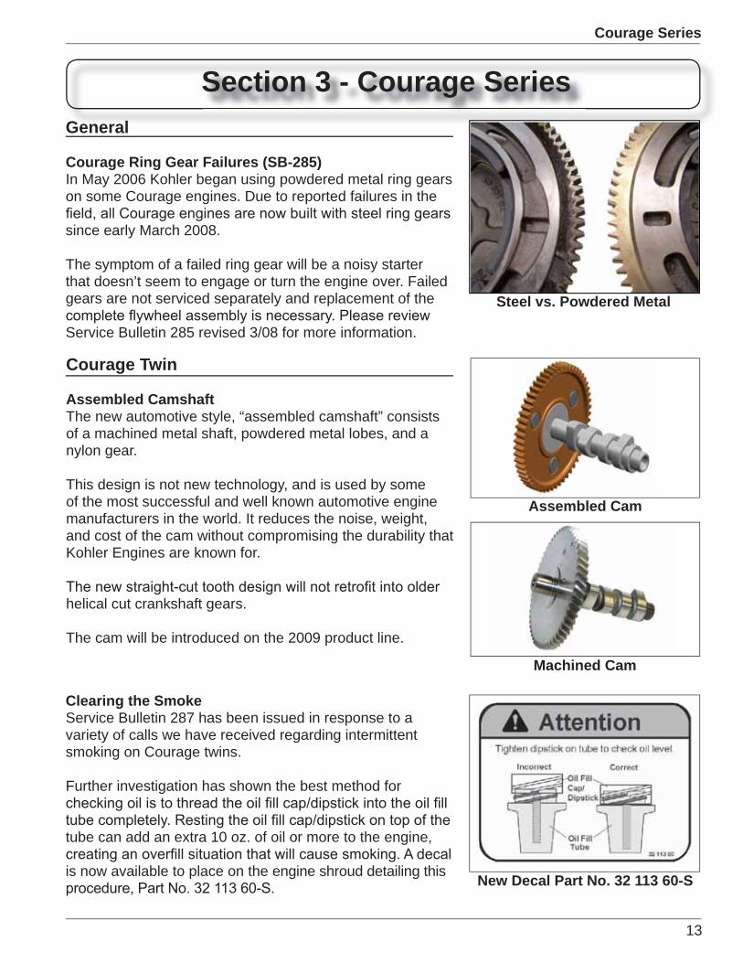
Courage Ring Gear Failures (SB-285)In May 2006 Kohler began using powdered metal ring gears on some Courage engines. Due to reported failures in the
since early March 2008.
The symptom of a failed ring gear will be a noisy starter that doesn’t seem to engage or turn the engine over. Failed gears are not serviced separately and replacement of the
Service Bulletin 285 revised 3/08 for more information.
Steel vs. Powdered Metal
Clearing the SmokeService Bulletin 287 has been issued in response to a variety of calls we have received regarding intermittent smoking on Courage twins.
Further investigation has shown the best method for
tube can add an extra 10 oz. of oil or more to the engine,
is now available to place on the engine shroud detailing this New Decal Part No. 32 113 60-S
14
Courage Series
Emissions StatementWe are updating the Owner’s Manual regarding emissions compliance. We are adding a statement that will recommend the combustion chamber be cleaned between 200 and 400 hours to retain emission compliance status.
This is recommended but not required and will be left to the discretion of the consumer.
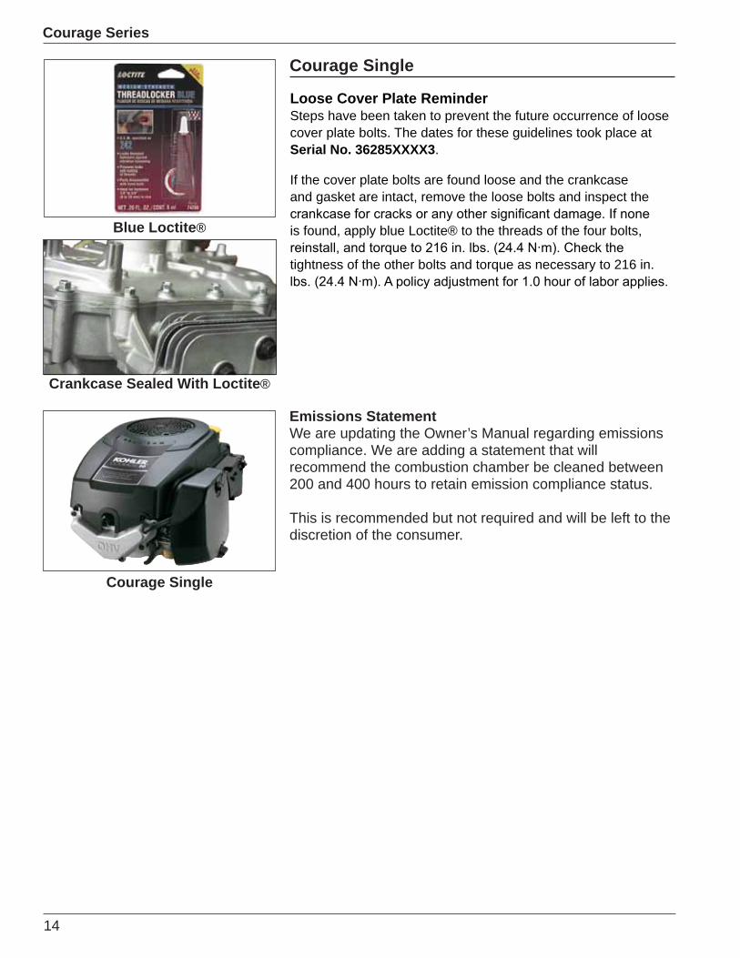
Loose Cover Plate ReminderSteps have been taken to prevent the future occurrence of loose cover plate bolts. The dates for these guidelines took place at Serial No. 36285XXXX3.
If the cover plate bolts are found loose and the crankcase and gasket are intact, remove the loose bolts and inspect the
is found, apply blue Loctite® to the threads of the four bolts,
tightness of the other bolts and torque as necessary to 216 in.
Blue Loctite®
Courage Single
Crankcase Sealed With Loctite®
Courage Single
15
Courage Series
New Cam DesignThe new design cam reduces the number of parts in the engine as the gear, lobe, and shaft will be assembled as one part.
The assembled cam will provide quality control and consistency in production on the Courage engine equal to the Command Series engines. The design will implement powdered metal lobes that are precision controlled with an
the cam on the Courage Twin.Assembled Cam
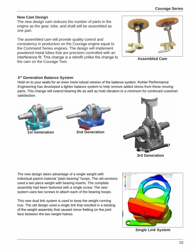
3rd Generation Balance System
Engineering has developed a lighter balance system to help remove added stress from these moving parts. This change will extend bearing life as well as hold vibration to a minimum for continued customer satisfaction.
1st Generation 2nd Generation
3rd Generation
Single Link System
The new design takes advantage of a single weight with individual parent material “plain bearing” hoops. The old versions used a two piece weight with bearing inserts. The complete assembly had been fastened with a single screw. The new system uses two screws to attach each of the bearing hoops.
This new dual link system is used to keep the weight running true. The old design used a single link that resulted in a twisting
face between the two weight halves.
16
Courage Series
Less reciprocating mass means less force to balance within the system. That means lower bearing loads and longer engine life. To accomplish this, the piston was completely redesigned to
Wider skirt for better heat transfer from the crown
Skirt is 2 mm longer for a better guide in the boreReduced pin diameter from 22 mm to 20 mm
••••
Old vs. New Piston
Old Style
New Style
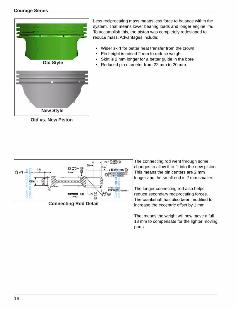
The connecting rod went through some
This means the pin centers are 2 mm longer and the small end is 2 mm smaller.
The longer connecting rod also helps reduce secondary reciprocating forces.
increase the eccentric offset by 1 mm.
That means the weight will now move a full 18 mm to compensate for the lighter moving parts.
Connecting Rod Detail

17
Courage Series
Crankshaft Detail
“2” Indicates New Balance
System
“3” IndicatesCARB Tier III
Decal ReminderWhen placing the decal for the short
next to the original engine decal, not over it.
The original engine information will be required when servicing any external
components.
offset by 1 mm. That means the weight will now move a full 18 mm to compensate for the lighter moving parts.
system resulted in many changes on the inside. Engine specs will change to make servicing the engine as easy as possible.
SV540-3216
New Balance System Incorporated into Short BlocksBeginning September 16, 2008 a new balance system with a common bore size was implemented
being assembled to service engines built before and after that date.
In order to keep the older engines emission compliant, the new short blocks for the SV470-540 will include a matching carburetor which must be installed as part of the repair.
chart has been created to identify the correct part number to be ordered. Use the chart listed
Engine Model Fuel System Type Short Block to Order
SV470/480 Pressure Flow 20 522 08SV470/480 Gravity Flow 20 522 09SV530/540 Pressure Flow 20 522 10SV530/540 Gravity Flow 20 522 11SV590/600 All 20 522 05SV610/620 All 20 522 07
18
Courage Series
Courage XT
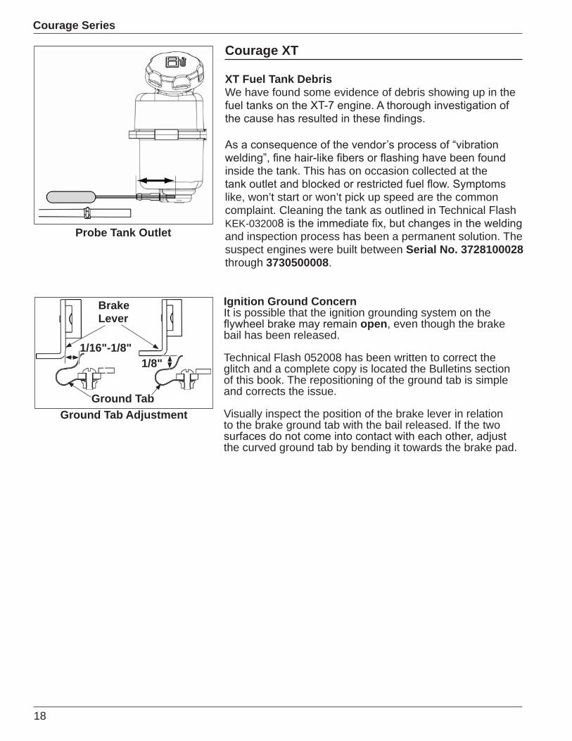
XT Fuel Tank DebrisWe have found some evidence of debris showing up in the
inside the tank. This has on occasion collected at the
like, won’t start or won’t pick up speed are the common complaint. Cleaning the tank as outlined in Technical Flash KEK-03200and inspection process has been a permanent solution. The suspect engines were built between Serial No. 3728100028 through 3730500008.
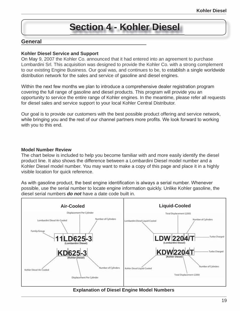
Ignition Ground ConcernIt is possible that the ignition grounding system on the
open, even though the brake bail has been released.
Technical Flash 052008 has been written to correct the glitch and a complete copy is located the Bulletins section of this book. The repositioning of the ground tab is simple and corrects the issue.
Visually inspect the position of the brake lever in relation to the brake ground tab with the bail released. If the two
the curved ground tab by bending it towards the brake pad.
Probe Tank Outlet
Ground Tab Adjustment
BrakeLever
Ground Tab
1/16"-1/8"1/8"
19
Kohler Diesel
Section 4 - Kohler Diesel
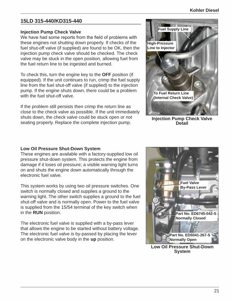
Model Number ReviewThe chart below is included to help you become familiar with and more easily identify the diesel product line. It also shows the difference between a Lombardini Diesel model number and a Kohler Diesel model number. You may want to make a copy of this page and place it in a highly visible location for quick reference.
possible, use the serial number to locate engine information quickly. Unlike Kohler gasoline, the diesel serial numbers do not have a date code built in.
Air-Cooled Liquid-Cooled
Explanation of Diesel Engine Model Numbers
General
Kohler Diesel Service and SupportOn May 9, 2007 the Kohler Co. announced that it had entered into an agreement to purchase Lombardini Srl. This acquisition was designed to provide the Kohler Co. with a strong complement to our existing Engine Business. Our goal was, and continues to be, to establish a single worldwide distribution network for the sales and service of gasoline and diesel engines.
covering the full range of gasoline and diesel products. This program will provide you an opportunity to service the entire range of Kohler engines. In the meantime, please refer all requests for diesel sales and service support to your local Kohler Central Distributor.
Our goal is to provide our customers with the best possible product offering and service network,
with you to this end.

20
Kohler Diesel
15LD 400/KD400
Hydraulic Lifter Rocker Arm Torque Procedure
the hydraulic lifter rocker arm torque procedure on these engines. The engine uses hydraulic lifters so no valve settings are required. To properly install the rocker arms on this engine follow the instructions below.
1. Make sure the piston is at bottom dead center. 2. Install spacer making sure that the tab on the spacer is
aligned with the slot in the cylinder head.3. Install rocker arm, washer, and nut making sure the
push rod is correctly installed in the lifter.4. Carefully torque the hold down nut to 10 N·m (7.38 ft. lbs.).5. Allow the engine to sit for approximately four hours to
allow the lifters to bleed down.
using the recoil starter (do not engage starter motor), or by hand to ensure there is no contact between the valves and the piston.
7. Retorque the hold down nut to 10 N·m (7.38 ft. lbs.).
Rocker Arm Spacer Installed
Rocker Arm Assembly Installed
All Air-Cooled Series
Quick Stop Device (QSD)The quick stop device system, or QSD, is available on all multi-cylinder air-cooled series engines. The system uses an electric solenoid in conjunction with the fuel lift pump and check valves to quickly shut down the engine.
Use of an auxiliary fuel pump before the QSD is not recommended. It is possible that the auxiliary pump can push fuel past the plunger of the QSD and allow the engine to continue running after power is removed from the solenoid.
before the QSD to protect the plunger from being damaged by possible contaminates in the fuel system. The in-line
QSD Fuel Line Routing
Outlet to Fuel Lift Pump Inlet
Inlet From Fuel Lift Pump Outlet
Outlet to Injection Pump Inlet
Inlet From Fuel Tank
Air Bleed Screw
21
Kohler Diesel
15LD 315-440/KD315-440
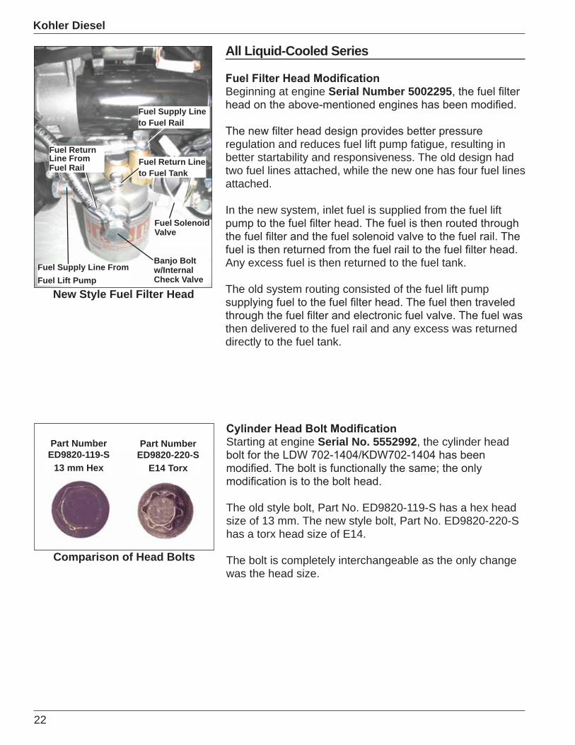
Injection Pump Check Valve
these engines not shutting down properly. If checks of the fuel shut-off valve (if supplied) are found to be OK, then the injection pump check valve should be checked. The check valve may be stuck in the open position, allowing fuel from the fuel return line to be ingested and burned.
To check this, turn the engine key to the OFF position (if equipped). If the unit continues to run, crimp the fuel supply line from the fuel shut-off valve (if supplied) to the injection pump. If the engine shuts down, there could be a problem with the fuel shut-off valve.
If the problem still persists then crimp the return line as close to the check valve as possible. If the unit immediately shuts down, the check valve could be stuck open or not seating properly. Replace the complete injection pump.
Low Oil Pressure Shut-Down SystemThese engines are available with a factory-supplied low oil pressure shut-down system. This protects the engine from damage if it loses oil pressure; a visible warning light turns on and shuts the engine down automatically through the electronic fuel valve.
This system works by using two oil pressure switches. One switch is normally closed and supplies a ground to the warning light. The other switch supplies a ground to the fuel shut-off valve and is normally open. Power to the fuel valve is supplied from the 15/54 terminal of the key switch when in the RUN position.
The electronic fuel valve is supplied with a by-pass lever that allows the engine to be started without battery voltage. The electronic fuel valve is by-passed by placing the lever on the electronic valve body in the up position.
Low Oil Pressure Shut-Down System
Part No. ED6745-042-SNormally Closed
Part No. ED5041-267-SNormally Open
Fuel ValveBy-Pass Lever
Injection Pump Check Valve Detail
To Fuel Return Line(Internal Check Valve)
High-PressureLine to Injector
Fuel Supply Line
22
Kohler Diesel
All Liquid-Cooled Series
Beginning at engine Serial Number 5002295
regulation and reduces fuel lift pump fatigue, resulting in better startability and responsiveness. The old design had two fuel lines attached, while the new one has four fuel lines attached.
In the new system, inlet fuel is supplied from the fuel lift
Any excess fuel is then returned to the fuel tank.
The old system routing consisted of the fuel lift pump
then delivered to the fuel rail and any excess was returned directly to the fuel tank.
Fuel Solenoid Valve
Fuel Return Line From Fuel Rail
Banjo Bolt w/InternalCheck Valve
New Style Fuel Filter Head
Fuel Supply Line From Fuel Lift Pump
Fuel Supply Line to Fuel Rail
Fuel Return Line to Fuel Tank
Starting at engine Serial No. 5552992, the cylinder head
The old style bolt, Part No. ED9820-119-S has a hex head size of 13 mm. The new style bolt, Part No. ED9820-220-S has a torx head size of E14.
The bolt is completely interchangeable as the only change was the head size.
Part Number ED9820-119-S
13 mm Hex
Comparison of Head Bolts
Part Number ED9820-220-S
E14 Torx
23
Kohler Diesel
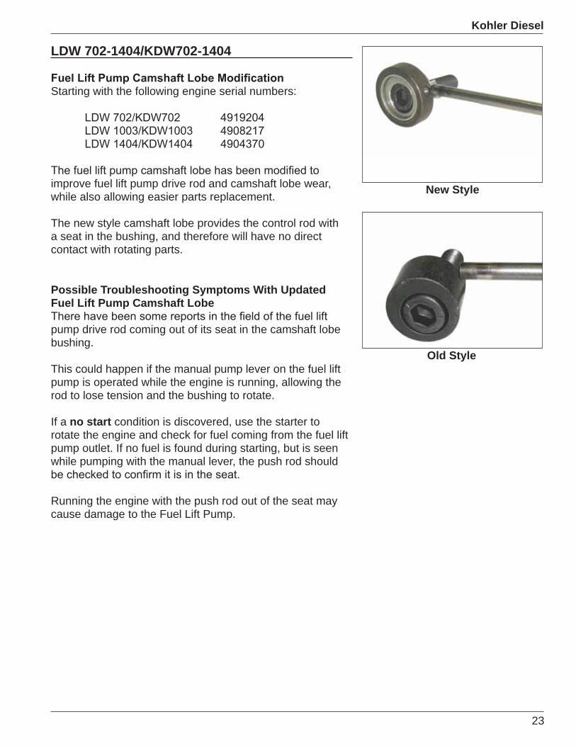
LDW 702-1404/KDW702-1404
Starting with the following engine serial numbers:
improve fuel lift pump drive rod and camshaft lobe wear, while also allowing easier parts replacement.
The new style camshaft lobe provides the control rod with a seat in the bushing, and therefore will have no direct contact with rotating parts.
Possible Troubleshooting Symptoms With Updated Fuel Lift Pump Camshaft Lobe
pump drive rod coming out of its seat in the camshaft lobe bushing.
This could happen if the manual pump lever on the fuel lift pump is operated while the engine is running, allowing the rod to lose tension and the bushing to rotate.
If a no start condition is discovered, use the starter to rotate the engine and check for fuel coming from the fuel lift pump outlet. If no fuel is found during starting, but is seen while pumping with the manual lever, the push rod should
Running the engine with the push rod out of the seat may cause damage to the Fuel Lift Pump.
New Style
Old Style
24
Kohler Diesel
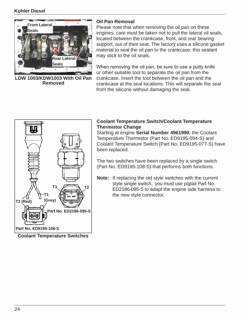
Oil Pan RemovalPlease note that when removing the oil pan on these engines, care must be taken not to pull the lateral oil seals, located between the crankcase, front, and rear bearing support, out of their seat. The factory uses a silicone gasket material to seal the oil pan to the crankcase; this sealant may stick to the oil seals.
or other suitable tool to separate the oil pan from the crankcase. Insert the tool between the oil pan and the crankcase at the seal locations. This will separate the seal from the silicone without damaging the seal.
Front Lateral Seals
Rear Lateral Seals
LDW 1003/KDW1003 With Oil Pan Removed
Coolant Temperature SwitchesPart No. ED9195-108-S
Part No. ED2186-095-S
T1 T2
T1(Grey)T2 (Red)
Coolant Temperature Switch/Coolant Temperature Thermistor ChangeStarting at engine Serial Number 4961990, the Coolant Temperature Thermistor (Part No. ED9195-094-S) and Coolant Temperature Switch (Part No. ED9195-077-S) have been replaced.
The two switches have been replaced by a single switch (Part No. ED9195-108-S) that performs both functions.
Note: If replacing the old style switches with the current style single switch, you must use pigtail Part No. ED2186-095-S to adapt the engine side harness to the new style connector.
25
Kohler Diesel
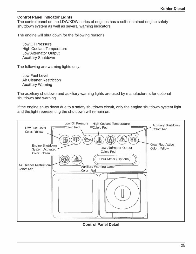
Control Panel Indicator Lights
shutdown system as well as several warning indicators.
The engine will shut down for the following reasons:
Low Oil PressureHigh Coolant TemperatureLow Alternator OutputAuxiliary Shutdown
The following are warning lights only:
Low Fuel LevelAir Cleaner Restriction
The auxiliary shutdown and auxiliary warning lights are used by manufacturers for optional shutdown and warning.
If the engine shuts down due to a safety shutdown circuit, only the engine shutdown system light and the light representing the shutdown will remain on.
Low Fuel LevelColor: Yellow
Auxiliary Warning Lamp Color: Red
Air Cleaner Restriction Color: Red
Engine Shutdown System ActivatedColor: Green
Low Oil PressureColor: Red
Low Alternator OutputColor: Red
High Coolant TemperatureColor: Red
Auxiliary ShutdownColor: Red
Glow Plug ActiveColor: Yellow
Hour Meter (Optional)
Control Panel Detail
26
Kohler Diesel
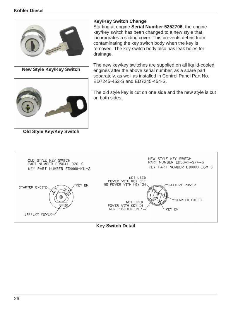
Key/Key Switch ChangeStarting at engine Serial Number 5252706, the engine key/key switch has been changed to a new style that incorporates a sliding cover. This prevents debris from contaminating the key switch body when the key is removed. The key switch body also has leak holes for drainage.
The new key/key switches are supplied on all liquid-cooled engines after the above serial number, as a spare part separately, as well as installed in Control Panel Part No. ED7245-453-S and ED7245-454-S.
The old style key is cut on one side and the new style is cut on both sides.
Old Style Key/Key Switch
New Style Key/Key Switch
Key Switch Detail
27
New Product
Section 5 - New Product
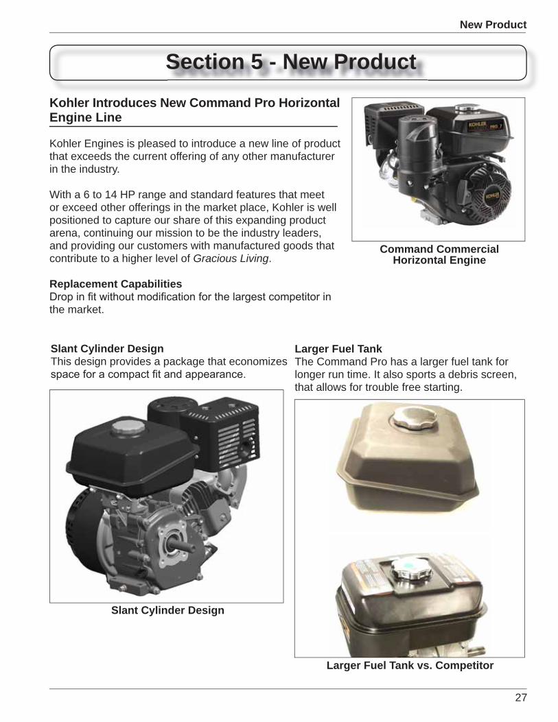
Kohler Introduces New Command Pro Horizontal Engine Line
Kohler Engines is pleased to introduce a new line of product that exceeds the current offering of any other manufacturer in the industry.
With a 6 to 14 HP range and standard features that meet or exceed other offerings in the market place, Kohler is well positioned to capture our share of this expanding product arena, continuing our mission to be the industry leaders, and providing our customers with manufactured goods that contribute to a higher level of Gracious Living.
Replacement Capabilities
the market.
Command Commercial Horizontal Engine
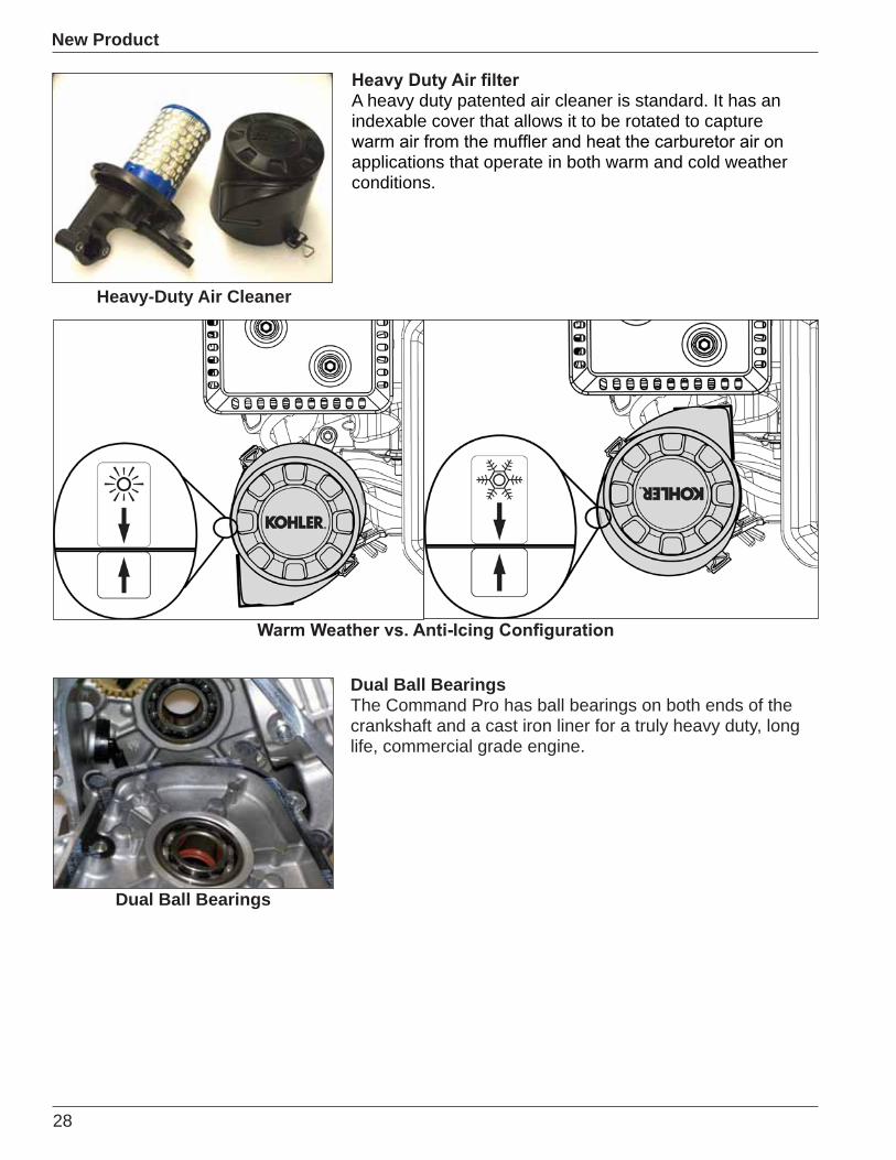
Slant Cylinder DesignThis design provides a package that economizes
Slant Cylinder Design
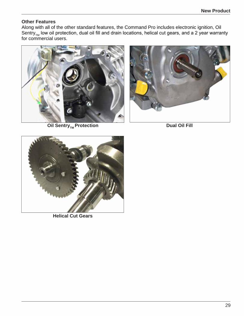
Larger Fuel TankThe Command Pro has a larger fuel tank for longer run time. It also sports a debris screen, that allows for trouble free starting.
Larger Fuel Tank vs. Competitor
28
New Product
A heavy duty patented air cleaner is standard. It has an indexable cover that allows it to be rotated to capture
applications that operate in both warm and cold weather conditions.
Dual Ball BearingsThe Command Pro has ball bearings on both ends of the crankshaft and a cast iron liner for a truly heavy duty, long life, commercial grade engine.
Dual Ball Bearings
Heavy-Duty Air Cleaner
29
New Product
Other FeaturesAlong with all of the other standard features, the Command Pro includes electronic ignition, Oil SentryTMfor commercial users.
Helical Cut Gears
Dual Oil FillOil SentryTM Protection

30
New Product
Kohler Enters Consumer Horizontal Market
The leader in commercial engine products is now manufacturing a line of horizontal consumer engines that has some of the same features as it commercial line.
The Slant cylinder overhead valve design engine line has a cast iron liner, dual ball bearings, water trap carburetor, and larger fuel tank (than competitive engines) which includes a serviceable debris screen, and it is all covered by a two year warranty.
Cast-Iron LinerThis feature is standard on the entire Kohler consumer line of engines. With proper care this feature will extend the life of the engine.
Dual Ball BearingsThis is a standard feature that does not appear on any of the competitive consumer engines. This feature sets the bar for the competition with a feature that is not always used on commercial engines.
Courage Horizontal Utility
Cast-Iron Liner
Dual Ball Bearings
31
New Product
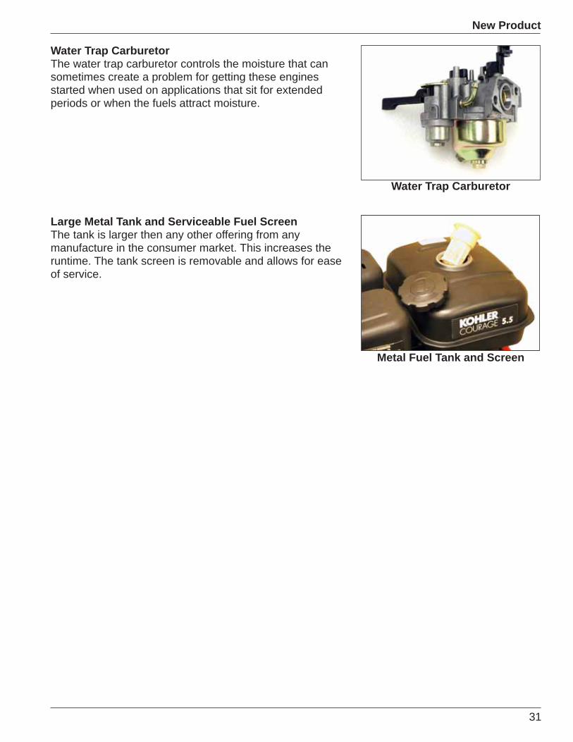
Water Trap CarburetorThe water trap carburetor controls the moisture that can sometimes create a problem for getting these engines started when used on applications that sit for extended periods or when the fuels attract moisture.
Large Metal Tank and Serviceable Fuel ScreenThe tank is larger then any other offering from any manufacture in the consumer market. This increases the runtime. The tank screen is removable and allows for ease of service.
Water Trap Carburetor
Metal Fuel Tank and Screen

32
New Product
New Commercial EFI
Introducing the all new self-contained EFI system from Kohler Engines. This “Closed Loop” “Sequential Fuel Injection” system has all the advantages of the current system and more.
The self contained system means that all the previously added components are now mounted to the engine and include:
• Fuel Pump• Fuel Pressure Regulator• Electronic Control Unit
This makes mounting the engine as simple as any carburetor system without the need for a fuel return line.
Currently designed for Command Twins in both horizontal
the range covers from 19 to 41 HP engines.
engine scheduled in April of 2009 with additional models available monthly through 2010.
“Green” world wide emissions compliance means these engines are designed to meet the stringent requirements of EPA, California, and European regulatory agencies, and will be done without the use of expensive catalytic or air induction systems.
A “Flex Fuel” option of up to E85 will be available in 6 to 9 months after the start of production.
Current EFI sensors include:• Speed Sensor• Engine Oil/Coolant Temperature• Throttle Position Sensor• Oxygen Sensor (Single Wire)
New Commercial EFI additional sensors include:• Manifold Absolute Pressure (MAP) Sensor• Air Inlet Temperature Sensor• Oxygen Sensor (Heated 4 Wire)
Lower fuel consumption, depending on application load conditions, fuel savings are expected to be in the 15–30% range.
Consumer EFI with Heavy-Duty Air Cleaner System
33
New Product
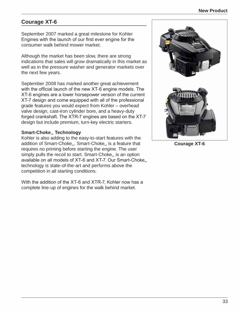
Courage XT-6
September 2007 marked a great milestone for Kohler
consumer walk behind mower market.
Although the market has been slow, there are strong indications that sales will grow dramatically in this market as well as in the pressure washer and generator markets over the next few years.
September 2008 has marked another great achievement
grade features you would expect from Kohler – overhead valve design, cast-iron cylinder bore, and a heavy-duty
design but include premium, turn-key electric starters.
Smart-Choke™ TechnologyKohler is also adding to the easy-to-start features with the addition of Smart-Choke™. Smart-Choke™ is a feature that requires no priming before starting the engine. The user simply pulls the recoil to start. Smart-Choke™ is an option
™technology is state-of-the-art and performs above the competition in all starting conditions.
complete line-up of engines for the walk behind market.
Courage XT-6

34
New Product
35
Miscellaneous
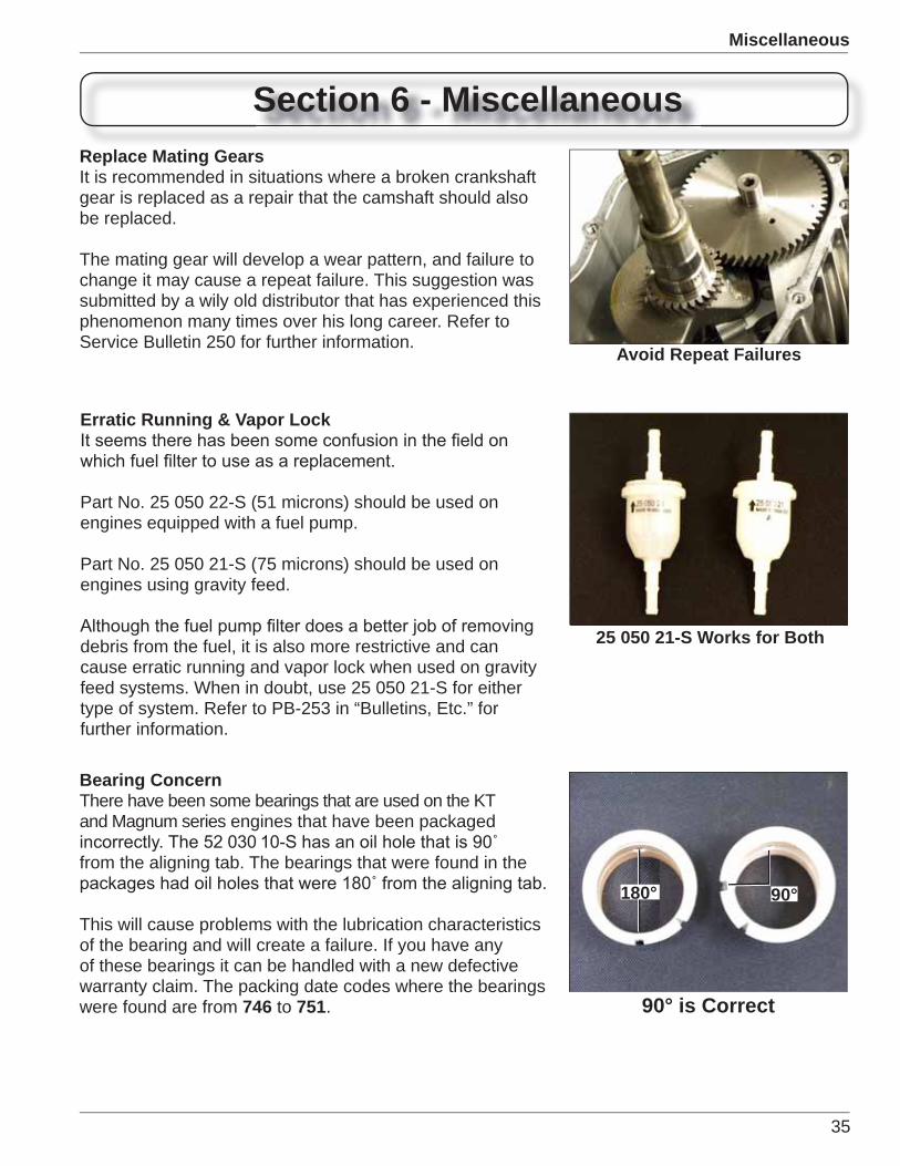
Section 6 - MiscellaneousReplace Mating GearsIt is recommended in situations where a broken crankshaft gear is replaced as a repair that the camshaft should also be replaced.
The mating gear will develop a wear pattern, and failure to change it may cause a repeat failure. This suggestion was submitted by a wily old distributor that has experienced this phenomenon many times over his long career. Refer to Service Bulletin 250 for further information.
Avoid Repeat Failures
Erratic Running & Vapor Lock
Part No. 25 050 22-S (51 microns) should be used on engines equipped with a fuel pump.
Part No. 25 050 21-S (75 microns) should be used on engines using gravity feed.
debris from the fuel, it is also more restrictive and can cause erratic running and vapor lock when used on gravity feed systems. When in doubt, use 25 050 21-S for either type of system. Refer to PB-253 in “Bulletins, Etc.” for further information.
25 050 21-S Works for Both
Bearing ConcernThere have been some bearings that are used on the KT and Magnum series engines that have been packaged
from the aligning tab. The bearings that were found in the
This will cause problems with the lubrication characteristics of the bearing and will create a failure. If you have any of these bearings it can be handled with a new defective warranty claim. The packing date codes where the bearings were found are from 746 to 751. 90° is Correct
180° 90°

36
Miscellaneous
1800 36001 40 808 320 640
100 4,000 8,000200 8,000 16,000500 20,000 40,000
2,000 80,000 160,0003,000 120,000 240,000
Makes You Think...This information came from a service bulletin written by an OEM in the mid ‘70’s. Although there are many factors that play into the life expectancy of an engine, such as maintenance and care, the time factors and comparisons made in the bulletin make you think.
An engine that runs at 1800 RPM for one hour is equivalent to a car run at 40 miles per hour for one hour.
An engine that runs at 3600 RPM for 1 hour at twice the RPM is the equivalent to a car run at 80 miles per hour for 1 hour.
Most generator engine speeds vary in operation over
precision it needs, but the numbers may open the eyes of a customer who does not give the equipment the required care it deserves.
A generator that operates under load for 100 hours is equivalent to 8,000 miles on a car. This equates to only running the engine for 2 hours per week over one year’s
per week for 52 weeks (depending on the load) would be the same as putting between 62,400 to 124,000 miles a year on a car.
What would the maintenance requirements be, versus what they actually receive? Makes you think.
Miles Traveled vs. RPM
Ditch Witch® DipstickThrough a recent agreement between Ditch Witch® and
is being used. The two specs being used are 76640 and CH750-0032.
Because of the position of the engine and the unusual
not available in our system. Due to the small volume of
These parts will not appear on the parts drawing and the parts list will indicate “OEM supplied.”
OEM Parts
Miles vs. RPMHours
37
Miscellaneous
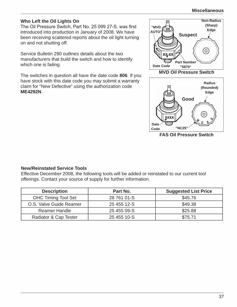
Who Left the Oil Lights On
introduced into production in January of 2008. We have been receiving scattered reports about the oil light turning on and not shutting off.
Service Bulletin 290 outlines details about the two manufacturers that build the switch and how to identify which one is failing.
The switches in question all have the date code 806. If you have stock with this date code you may submit a warranty claim for “New Defective” using the authorization code ME4292N.
MVD Oil Pressure Switch
FAS Oil Pressure Switch
Suspect
Date CodePart Number
"5870"
"MVDAUTO"
Non-Radius(Sharp)Edge
DateCode "NC25"
Radius(Rounded)
Edge
Good
New/Reinstated Service ToolsEffective December 2008, the following tools will be added or reinstated to our current tool offerings. Contact your source of supply for further information.
Description Part No. Suggested List PriceOHC Timing Tool Set 28 761 01-S $45.76
O.S. Valve Guide Reamer 25 455 12-S $49.38Reamer Handle 25 455 09-S $25.88
Radiator & Cap Tester 25 455 10-S $75.71
38
Miscellaneous
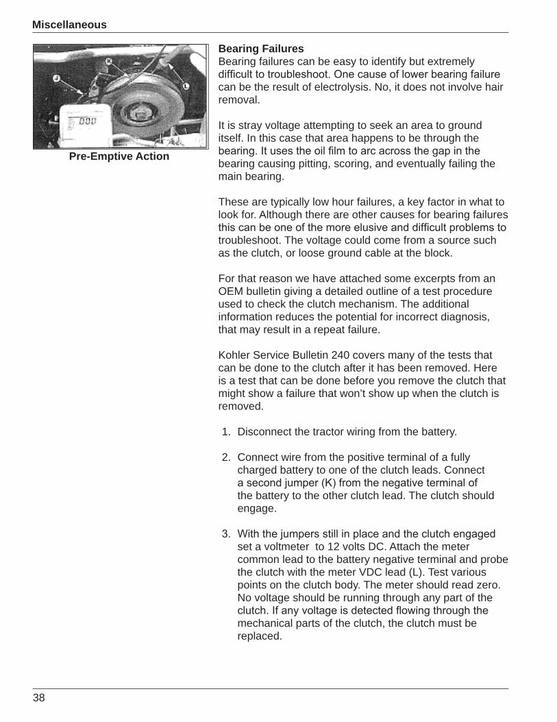
Bearing FailuresBearing failures can be easy to identify but extremely
can be the result of electrolysis. No, it does not involve hair removal.
It is stray voltage attempting to seek an area to ground itself. In this case that area happens to be through the
bearing causing pitting, scoring, and eventually failing the main bearing.
These are typically low hour failures, a key factor in what to look for. Although there are other causes for bearing failures
troubleshoot. The voltage could come from a source such as the clutch, or loose ground cable at the block.
For that reason we have attached some excerpts from an OEM bulletin giving a detailed outline of a test procedure used to check the clutch mechanism. The additional information reduces the potential for incorrect diagnosis, that may result in a repeat failure.
Kohler Service Bulletin 240 covers many of the tests that can be done to the clutch after it has been removed. Here is a test that can be done before you remove the clutch that might show a failure that won’t show up when the clutch is removed.
1. Disconnect the tractor wiring from the battery.
2. Connect wire from the positive terminal of a fully charged battery to one of the clutch leads. Connect
the battery to the other clutch lead. The clutch should engage.
set a voltmeter to 12 volts DC. Attach the meter common lead to the battery negative terminal and probe the clutch with the meter VDC lead (L). Test various points on the clutch body. The meter should read zero. No voltage should be running through any part of the
mechanical parts of the clutch, the clutch must be replaced.
Pre-Emptive Action
39
Miscellaneous
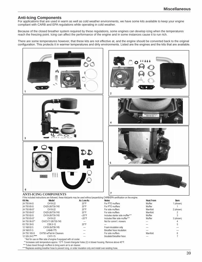
Anti-Icing ComponentsFor applications that are used in warm as well as cold weather environments, we have some kits available to keep your engine compliant with CARB and EPA regulations while operating in cold weather.
Because of the closed breather system required by these regulations, some engines can develop icing when the temperatures reach the freezing point. Icing can affect the performance of the engine and in some instances cause it to run rich.
There are some temperatures however, that these kits are not effective at, and the engine should be converted back to the original
ANTI-ICING COMPONENTS
Kit No. Model As Low As Notes Heat From Item
12 168 02-S CH18-26/730-745 — Foam insulation only — —24 168 01-S LH640-775 — Breather hose insulation — —
12 326 24-S**** CH11-15 — Insulated breather hose — 7
12
3
4
7
5
6
40
Miscellaneous
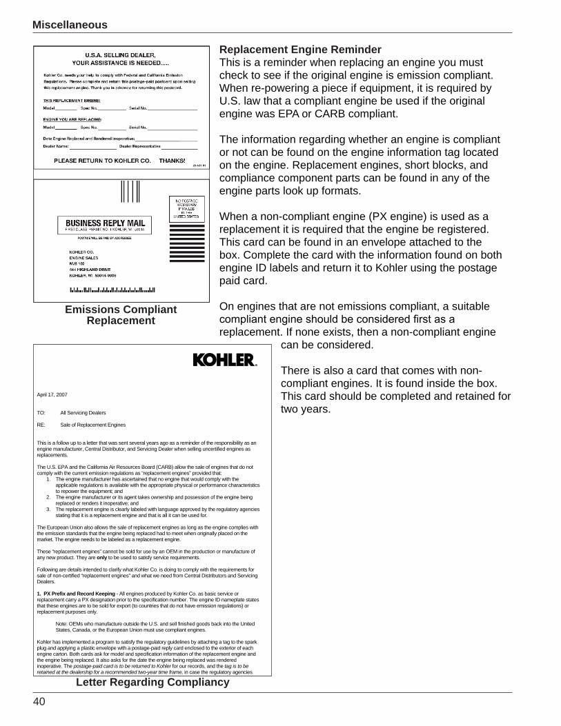
Replacement Engine ReminderThis is a reminder when replacing an engine you must check to see if the original engine is emission compliant. When re-powering a piece if equipment, it is required by U.S. law that a compliant engine be used if the original engine was EPA or CARB compliant.
The information regarding whether an engine is compliant or not can be found on the engine information tag located on the engine. Replacement engines, short blocks, and compliance component parts can be found in any of the engine parts look up formats.
When a non-compliant engine (PX engine) is used as a replacement it is required that the engine be registered. This card can be found in an envelope attached to the box. Complete the card with the information found on both engine ID labels and return it to Kohler using the postage paid card.
On engines that are not emissions compliant, a suitable
replacement. If none exists, then a non-compliant engine can be considered.
There is also a card that comes with non-compliant engines. It is found inside the box.This card should be completed and retained for two years.
Emissions CompliantReplacement
April 17, 2007
TO: All Servicing Dealers
RE: Sale of Replacement Engines
This is a follow up to a letter that was sent several years ago as a reminder of the responsibility as an engine manufacturer, Central Distributor, and Servicing Dealer when selling uncertified engines as replacements.
The U.S. EPA and the California Air Resources Board (CARB) allow the sale of engines that do not comply with the current emission regulations as “replacement engines” provided that:
1. The engine manufacturer has ascertained that no engine that would comply with the applicable regulations is available with the appropriate physical or performance characteristics to repower the equipment; and
2. The engine manufacturer or its agent takes ownership and possession of the engine being replaced or renders it inoperative; and
3. The replacement engine is clearly labeled with language approved by the regulatory agencies stating that it is a replacement engine and that is all it can be used for.
The European Union also allows the sale of replacement engines as long as the engine complies with the emission standards that the engine being replaced had to meet when originally placed on the market. The engine needs to be labeled as a replacement engine.
These “replacement engines” cannot be sold for use by an OEM in the production or manufacture of any new product. They are only to be used to satisfy service requirements.
Following are details intended to clarify what Kohler Co. is doing to comply with the requirements for sale of non-certified “replacement engines” and what we need from Central Distributors and Servicing Dealers.
1. PX Prefix and Record Keeping - All engines produced by Kohler Co. as basic service or replacement carry a PX designation prior to the specification number. The engine ID nameplate states that these engines are to be sold for export (to countries that do not have emission regulations) or replacement purposes only.
Note: OEMs who manufacture outside the U.S. and sell finished goods back into the United States, Canada, or the European Union must use compliant engines.
Kohler has implemented a program to satisfy the regulatory guidelines by attaching a tag to the spark plug and applying a plastic envelope with a postage-paid reply card enclosed to the exterior of each engine carton. Both cards ask for model and specification information of the replacement engine and the engine being replaced. It also asks for the date the engine being replaced was rendered inoperative. The postage-paid card is to be returned to Kohler for our records, and the tag is to be retained at the dealership for a recommended two-year time frame, in case the regulatory agencies
Letter Regarding Compliancy
41
Miscellaneous
Step 1 Step 1Step 2 Step 2Step 2 Step 2Step 4 Step 4Step 4 Step 4Step 5 Step 5Step 6 Step 6
(list none if corrective actions were not needed)
Kohler Starting Circuit Test Procedure
Ambient Air Temperature:
Operating Hours:
Use attached sheet(s) for test procedures and insert results on this form.
Second test should be completed to either confirm first test results or after completing corrective actions.
Engine Model:
Engine Serial Number:Engine Specification:
Initial Testing Second Testing
Date of Purchase:Date of Test:
Battery Date: Battery CA:Battery CCA:
Description of what Corrective Actions were performed between Test 1 and 2
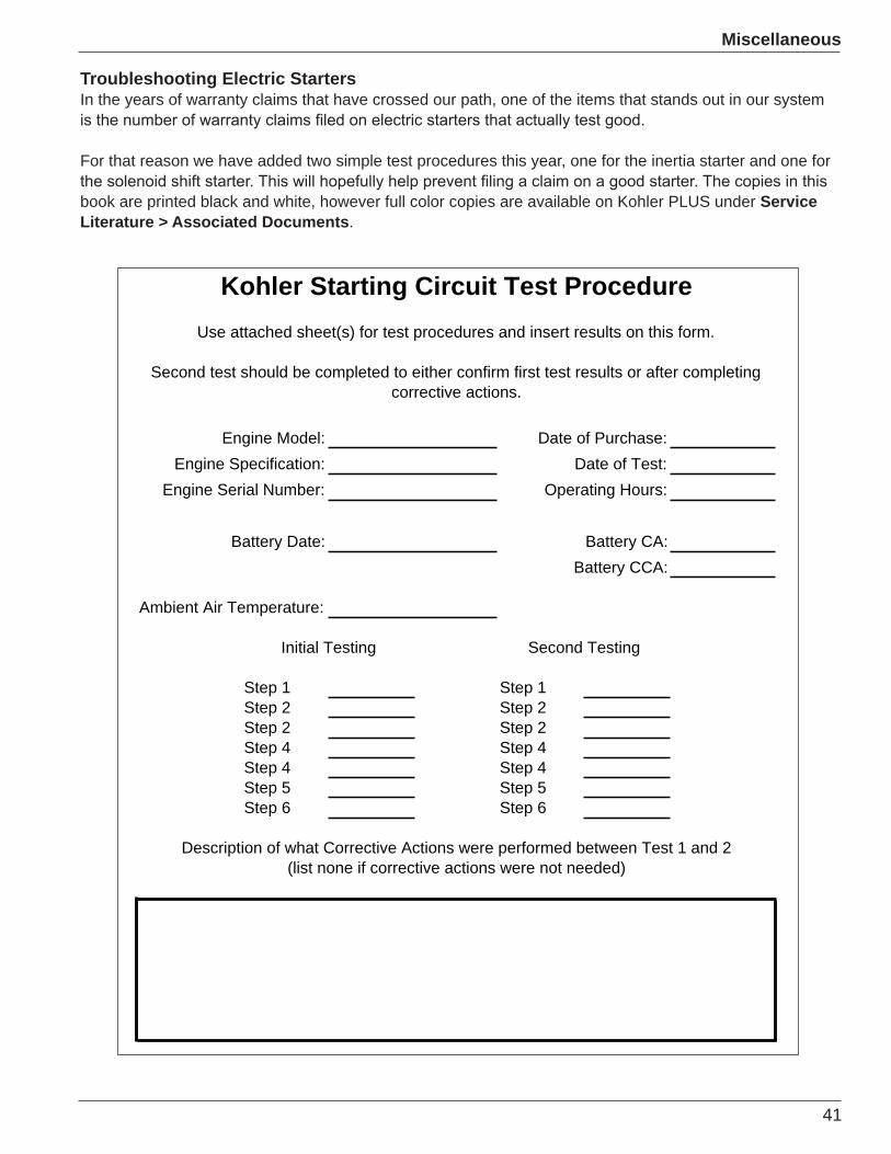
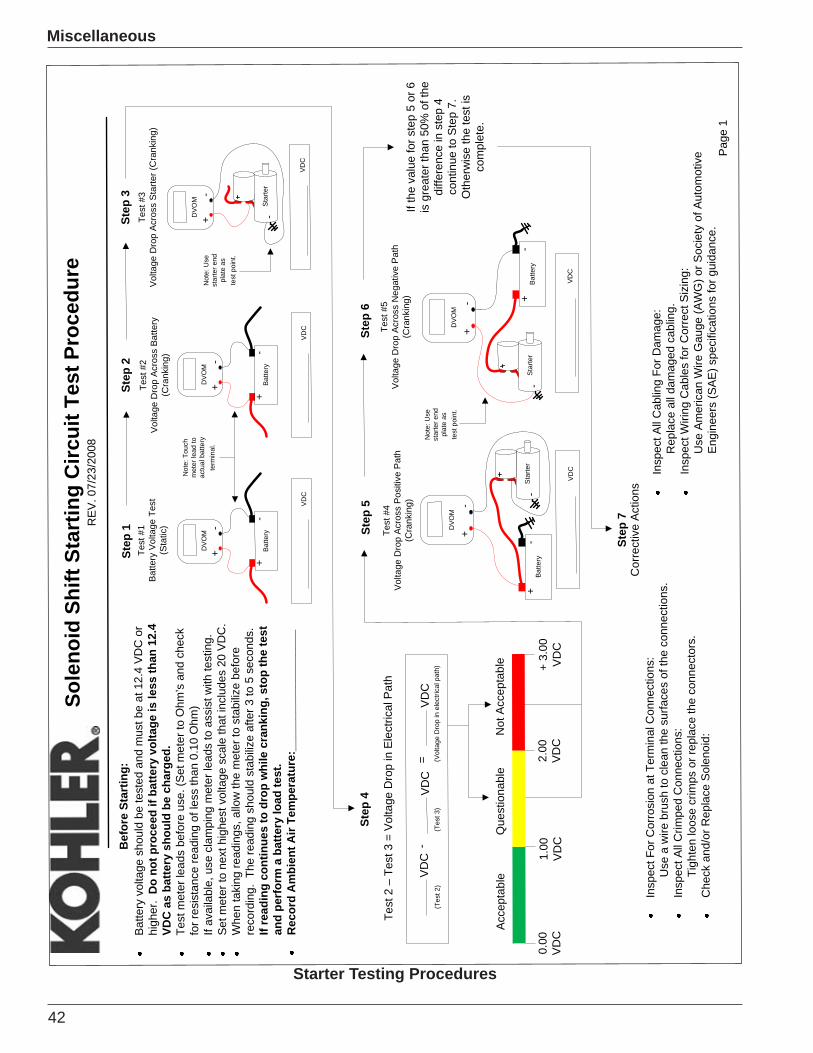
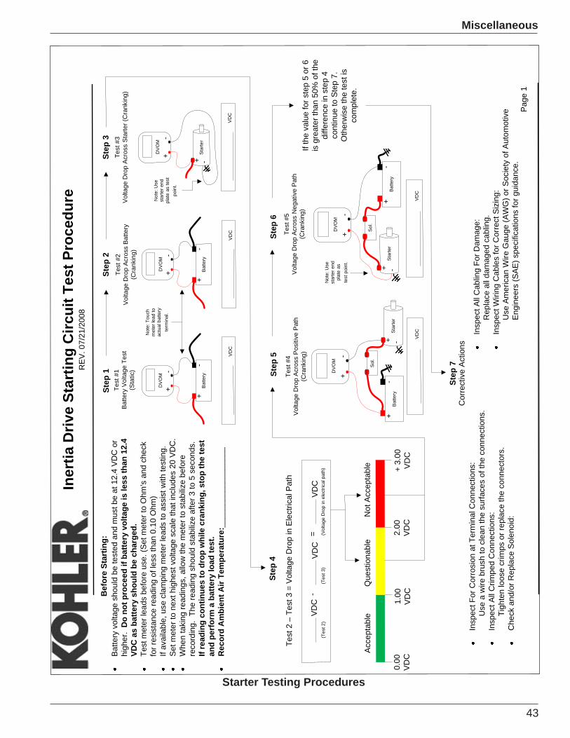
Troubleshooting Electric StartersIn the years of warranty claims that have crossed our path, one of the items that stands out in our system
For that reason we have added two simple test procedures this year, one for the inertia starter and one for
book are printed black and white, however full color copies are available on Kohler PLUS under ServiceLiterature > Associated Documents.
42
Miscellaneous
Page
1
Sole
noid
Shi
ft St
artin
g C
ircui
t Tes
t Pro
cedu
reR
EV. 0
7/23
/200
8
Bef
ore
Star
ting:
Batte
ry v
olta
ge s
houl
dbe
test
ed a
ndm
ust b
e at
12.
4VD
C o
r hi
gher
.D
o no
t pro
ceed
ifba
ttery
volta
geis
less
than
12.
4VD
C a
s ba
ttery
sho
uld
be c
harg
ed.
Test
met
er le
ads
befo
re u
se. (
Set m
eter
to O
hm’s
and
chec
kfo
r res
ista
nce
read
ing
ofle
ssth
an 0
.10
Ohm
)If
avai
labl
e, u
se c
lam
ping
met
erle
ads
to a
ssis
t with
test
ing.
Set m
eter
tone
xt h
ighe
st v
olta
ge s
cale
that
incl
udes
20VD
C.
Whe
n ta
king
read
ings
, allo
w th
e m
eter
to s
tabi
lize
befo
re
reco
rdin
g.Th
e re
adin
gsh
ould
stab
ilize
afte
r 3 to
5 s
econ
ds.
Ifre
adin
g co
ntin
ues
to d
rop
whi
le c
rank
ing,
sto
pth
e te
stan
d pe
rfor
m a
bat
tery
load
test
.R
ecor
dA
mbi
ent A
ir Te
mpe
ratu
re:_
____
____
____
____
__
Test
#2
Vol
tage
Dro
p Ac
ross
Bat
tery
(Cra
nkin
g)
Step
2
VD
C
Bat
tery
+-
+-
DV
OM
Test
#1
Batte
ry V
olta
ge T
est
(Sta
tic)
Step
1
VD
C
Bat
tery
+-
+-
DV
OM
Test
#3
Vol
tage
Dro
p A
cros
s S
tarte
r (C
rank
ing)
VD
C
+-
DV
OM
Step
3
Step
7C
orre
ctiv
e A
ctio
ns
Ifth
e va
lue
for s
tep
5 or
6
isgr
eate
rtha
n 50
% o
f the
diffe
renc
ein
ste
p 4
cont
inue
to S
tep
7.O
ther
wis
e th
ete
stis
com
plet
e.
Test
#4
Volta
geD
rop
Acr
oss
Pos
itive
Pat
h(C
rank
ing)
VD
C
+-
DVO
M
Bat
tery
+-
Step
5Te
st #
5V
olta
ge D
rop
Acro
ss N
egat
ive
Pat
h(C
rank
ing)
Step
6
VDC
+-
DVO
M
Bat
tery
+-
Insp
ect F
or C
orro
sion
at T
erm
inal
Con
nect
ions
:U
se a
wire
bru
sh to
clea
nth
e su
rface
s of
the
conn
ectio
ns.
Insp
ect A
ll C
rimpe
d C
onne
ctio
ns:
Tigh
ten
loos
ecr
imps
or r
epla
ceth
e co
nnec
tors
.C
heck
and
/or R
epla
ceSo
leno
id:
Test
2–
Test
3 =
Volta
ge D
rop
in E
lect
rical
Pat
h
VD
CVD
C-
=V
DC
Step
4
+ 3.
00V
DC
0.00
VD
C1.
00V
DC
2.00
VDC
Acc
epta
ble
Que
stio
nabl
eN
ot A
ccep
tabl
e
Insp
ect A
ll C
ablin
g Fo
rDam
age:
Rep
lace
all
dam
aged
cab
ling.
Insp
ect W
iring
Cab
les
forC
orre
ctS
izin
g:U
seAm
eric
an W
ireG
auge
(AW
G) o
r Soc
iety
of A
utom
otiv
eE
ngin
eers
(SA
E) s
peci
ficat
ions
for g
uida
nce.
(Tes
t 2)
(Tes
t 3)
(
Volta
geD
rop
in e
lect
rical
pat
h)
Sta
rter
-
+
Star
ter
-
+
Star
ter
-
+
Not
e: U
se
star
ter e
ndpl
ate
aste
st p
oint
.
Not
e: U
sest
arte
r end
plat
e as
te
st p
oint
.
Not
e: T
ouch
met
er le
ad to
ac
tual
bat
tery
term
inal
.
Starter Testing Procedures
43
Miscellaneous
Page
1
Iner
tia D
rive
Star
ting
Circ
uit T
est P
roce
dure
REV
. 07/
21/2
008
Bef
ore
Star
ting:
Batte
ry v
olta
ge s
houl
dbe
test
ed a
ndm
ust b
e at
12.
4VD
C o
r hi
gher
.D
o no
t pro
ceed
ifba
ttery
volta
geis
less
than
12.
4VD
C a
s ba
ttery
sho
uld
be c
harg
ed.
Test
met
er le
ads
befo
re u
se. (
Set m
eter
to O
hm’s
and
chec
kfo
r res
ista
nce
read
ing
ofle
ssth
an 0
.10
Ohm
)If
avai
labl
e, u
se c
lam
ping
met
erle
ads
to a
ssis
t with
test
ing.
Set m
eter
tone
xt h
ighe
st v
olta
ge s
cale
that
incl
udes
20VD
C.
Whe
n ta
king
read
ings
, allo
w th
e m
eter
to s
tabi
lize
befo
re
reco
rdin
g.Th
e re
adin
gsh
ould
stab
ilize
afte
r 3 to
5 s
econ
ds.
Ifre
adin
g co
ntin
ues
to d
rop
whi
le c
rank
ing,
sto
pth
e te
stan
d pe
rfor
m a
bat
tery
load
test
.R
ecor
dA
mbi
ent A
ir Te
mpe
ratu
re:_
____
____
____
____
_
Test
#2
Vol
tage
Dro
p Ac
ross
Bat
tery
(Cra
nkin
g)
Step
2
VD
C
Bat
tery
+-
+-
DV
OM
Test
#1
Batte
ry V
olta
ge T
est
(Sta
tic)
Step
1
VD
C
Bat
tery
+-
+-
DV
OM
Test
#3
Vol
tage
Dro
p A
cros
s S
tarte
r (C
rank
ing)
VD
C
Sta
rter
+ -
+-
DV
OM
Step
3
Not
e: U
sest
arte
r end
pl
ate
as te
stpo
int.
Step
7C
orre
ctiv
e A
ctio
ns
Ifth
e va
lue
for s
tep
5 or
6
isgr
eate
rtha
n 50
% o
f the
diffe
renc
ein
ste
p 4
cont
inue
to S
tep
7.O
ther
wis
e th
ete
stis
com
plet
e.
Test
#4
Volta
geD
rop
Acr
oss
Pos
itive
Pat
h(C
rank
ing)
VD
CStar
ter
+ -
+-
DVO
M
Bat
tery
+-
Step
5
Sol
.
Test
#5
Vol
tage
Dro
p Ac
ross
Neg
ativ
e P
ath
(Cra
nkin
g)
Step
6
VDC
+-
DVO
M
Sol
.
Insp
ect F
or C
orro
sion
at T
erm
inal
Con
nect
ions
:U
se a
wire
bru
sh to
clea
nth
e su
rface
s of
the
conn
ectio
ns.
Insp
ect A
ll C
rimpe
d C
onne
ctio
ns:
Tigh
ten
loos
ecr
imps
or r
epla
ceth
e co
nnec
tors
.C
heck
and
/or R
epla
ceSo
leno
id:
Test
2–
Test
3 =
Volta
ge D
rop
in E
lect
rical
Pat
h
VD
CVD
C-
=V
DC
Step
4
+ 3.
00V
DC
0.00
VD
C1.
00V
DC
2.00
VDC
Acc
epta
ble
Que
stio
nabl
eN
ot A
ccep
tabl
e
Insp
ect A
ll C
ablin
g Fo
rDam
age:
Rep
lace
all
dam
aged
cab
ling.
Insp
ect W
iring
Cab
les
forC
orre
ctS
izin
g:U
seAm
eric
an W
ireG
auge
(AW
G) o
r Soc
iety
of A
utom
otiv
eE
ngin
eers
(SA
E) s
peci
ficat
ions
for g
uida
nce.
(Tes
t 2)
(Tes
t 3)
(
Volta
geD
rop
in e
lect
rical
pat
h)
Not
e: T
ouch
met
er le
ad to
ac
tual
bat
tery
term
inal
.
Not
e: U
se
star
ter e
ndpl
ate
as
test
poi
nt.
Bat
tery
+-
Sta
rter
+ -
Starter Testing Procedures
44
Miscellaneous
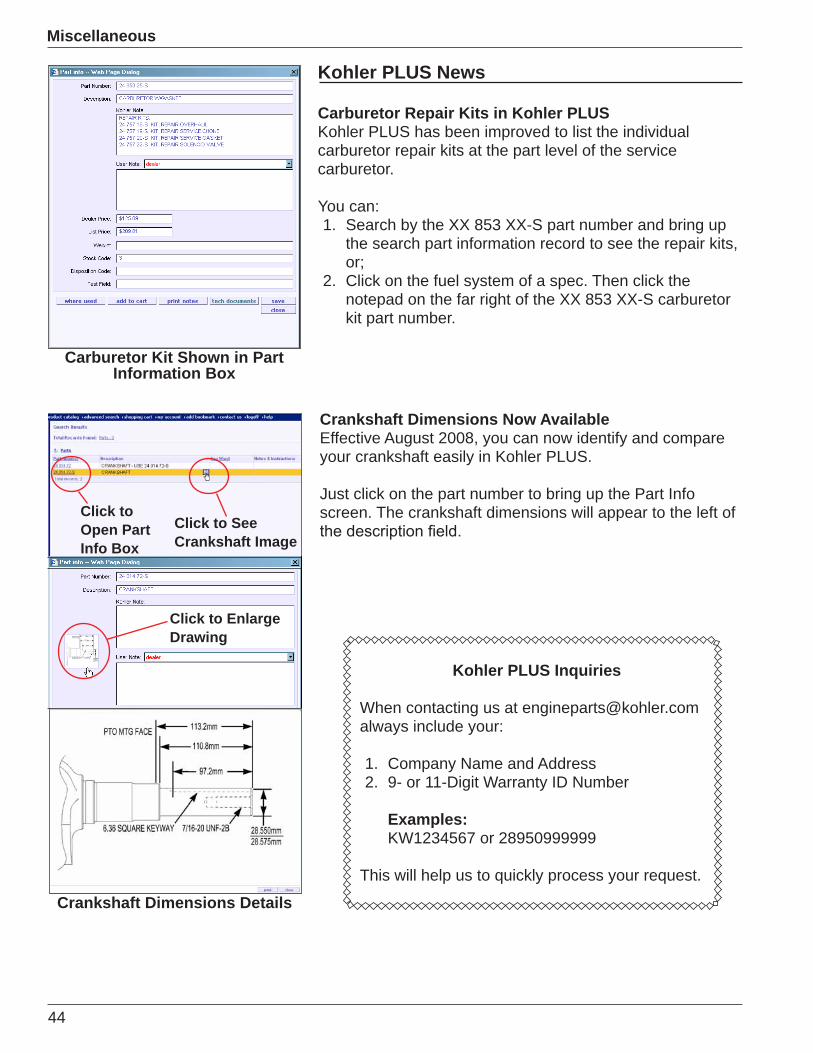
Kohler PLUS News
Carburetor Repair Kits in Kohler PLUSKohler PLUS has been improved to list the individual carburetor repair kits at the part level of the service carburetor.
You can:1. Search by the XX 853 XX-S part number and bring up
the search part information record to see the repair kits, or;
2. Click on the fuel system of a spec. Then click the notepad on the far right of the XX 853 XX-S carburetor kit part number.
Kohler PLUS Inquiries
When contacting us at [email protected] include your:
1. Company Name and Address2. 9- or 11-Digit Warranty ID Number
Examples: KW1234567 or 28950999999
This will help us to quickly process your request.
Crankshaft Dimensions Now AvailableEffective August 2008, you can now identify and compare your crankshaft easily in Kohler PLUS.
Just click on the part number to bring up the Part Info screen. The crankshaft dimensions will appear to the left of
Crankshaft Dimensions Details
Carburetor Kit Shown in Part Information Box
Click to Enlarge Drawing
Click toOpen Part Info Box
Click to See Crankshaft Image
45
Miscellaneous
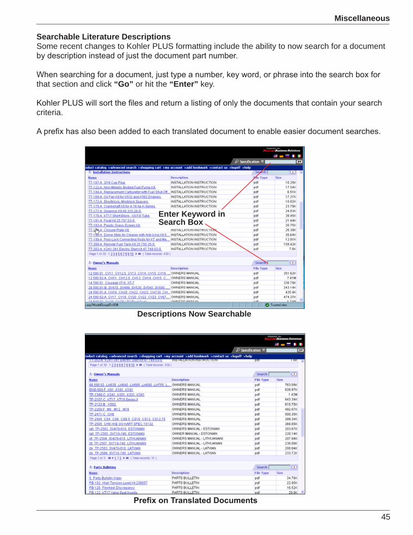
Descriptions Now Searchable
Searchable Literature Descriptions Some recent changes to Kohler PLUS formatting include the ability to now search for a document
that section and click “Go” or hit the “Enter” key.
criteria.
Enter Keyword in Search Box

46
Miscellaneous
Other Enhancements Now Available
RPM Idle and High Speed Settings -
Fast Moving Parts - found immediately below the engine group listings.
Click Here to View Image
News Flash on Kohler PLUSWe are now posting all new released literature into one location initially on
symbol, as shown to the left.
This section includes all NEW Service Bulletins, Parts Bulletins, Installation Instructions, Technical Flashes, Tech Tips, etc. The literature will be posted here for one month. We will also continue to post information under their
information.
Click Here to View Literature Relating to the Spec No.
47
Miscellaneous
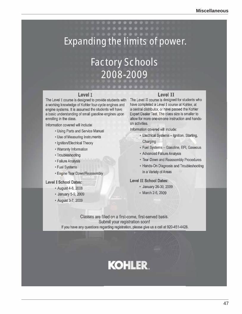
Factory Schools 2008-2009
Expanding the limits of power.
48
Miscellaneous
Telephone No.( ) -
Business Telephone Number ( )
Expert Dealer
Specialized Dealer
A check, money order, or credit card must be received with the application to reserve a place in the class. Class fees include the following:
• Lodging (if needed) Sunday evening through Friday morning. Long distance calls, and any in-room services are additional and will be payable to the hotel/motel upon checkout.
• Lunch and Breakfast, Monday through Thursday.• Transportation to and from classroom.• Instructional materials.• Thursday evening Awards banquet.• Framed diploma and uniform patches.• Factory tour (Friday morning).
You will be contacted with the school date choice(s) you have been accepted into once payment and registration are complete.
Make checks payable to “Kohler Co.” Make sure to reference “Factory School” and the month chosen in the memo section.
information:
Check One:
Name: (Please print as it appears on credit card):
Account Number:
Expiration Date:
Telephone Number: ( ) -
Fax the completed application to us at 920-459-1743.
If paying by check or money order, please mail the completed application and payment to address below:
Kohler Co. Engine Division School Reservations, MS 095 Kohler, WI 53044
Master Card Visa DiscoverAmericanExpress
- ) -
Choice of Dates:
1st Choice: 2nd Choice:
Company Name
Zip
Other
Kohler I.D. No. Date of Application
Company Address City State
Home Address Name of Applicant
State Zip
Authorized DealerYears of Industry Experience (Minimum 1 Year)
Fax Number (
City
4-Day Training Only (No Room Needed) - $250.00per personSingle Accommodations - $600.00 per personDouble Accommodations - $450.00 per person(When two students attend from the same company)
Please Check Room Preference:

49
Warranty News
Section 7 - Warranty NewsWarranty System NOW AVAILABLE
The Kohler Engine Division is pleased to announce the start of a new era. Our new Web-Based Warranty Processing System is now available.
This Web-Based Warranty System will provide users the capability to submit their own warranty claims, track progress of a warranty claim, and view their own dealership claim history.
Coupled with faster reimbursement, our new system will even provide the opportunity for a dealership to submit engine registration for the customer and print reports, such as the warranty claim reimbursement detail.
• To gain access to the system will require a USER Account be set up for you. Please contact your local CD representative, or call 866-255-9220. An individual user account will then be set up based on information provided by you. Each user will be requested to provide a special users name, password, position title, e-mail address and the First, Middle and Last name of the user.
• To access the new system via the Internet use the following address:
www.enginewarranty.kohlernet.com
• Training Manual is available ON-LINE
• Advantages o Easy to Use o Faster Payment o Increased Accuracy o Review Engine History by Serial Number o Review Dealership Information o Engine Registration
Login Screen
50
Warranty News
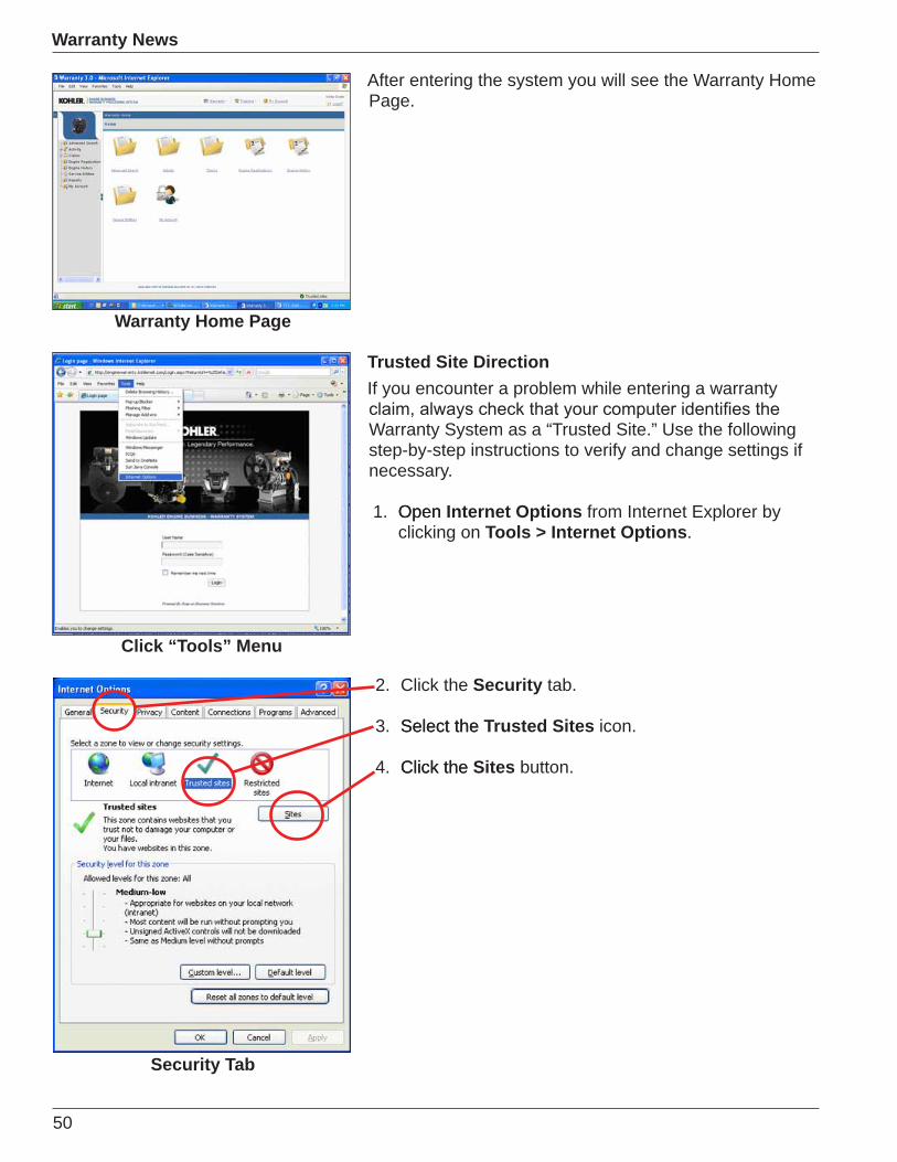
After entering the system you will see the Warranty Home Page.
Trusted Site DirectionIf you encounter a problem while entering a warranty
Warranty System as a “Trusted Site.” Use the following step-by-step instructions to verify and change settings if necessary.
1. OpenOpen Internet Options from Internet Explorer by clicking on Tools > Internet Options.
Security Tab
Click “Tools” Menu
Warranty Home Page
2. Click the Security tab.
3. Select theSelect the Trusted Sites icon.
4. Click theClick the Sites button.
51
Warranty News
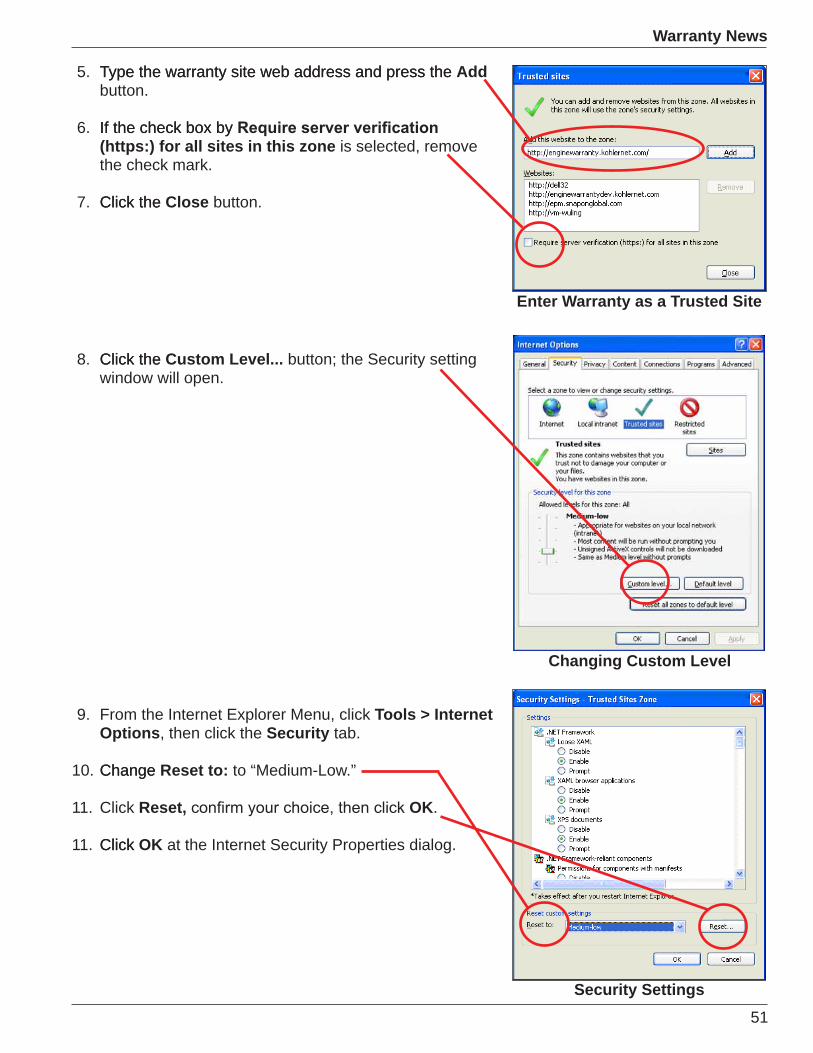
Enter Warranty as a Trusted Site
Security Settings
5. Type the warranty site web address and press theType the warranty site web address and press the Addbutton.
6. If the check box byIf the check box by(https:) for all sites in this zone is selected, remove the check mark.
7. Click theClick the Close button.
8. Click theClick the Custom Level... button; the Security setting window will open.
Changing Custom Level
9. From the Internet Explorer Menu, click Tools > Internet Options, then click the Security tab.
10. ChangeChange Reset to: to “Medium-Low.”
11. Click Reset, OK.
11. ClickClick OK at the Internet Security Properties dialog.
52
Warranty News
Helpful System Tips• To use the system, all users must obtain a User
Account to gain access. Contact your local CD or call the User Account Hot Line at 1-866-255-9220.
• Before using our new warranty system, please verify
address as a trusted site.
• The user name and password for Kohler PLUS and the new warranty system are typically not the same or shared.
• When entering a warranty claim always provide the engine serial number whenever possible.
• When entering the part number for the defect or replacement part, you must always use spaces and (-S) as required. Example 24 584 10-S.
• To enter labor in the labor operation section click the (+ Add Labor) button.
• After entering labor hours you must select the Enter/Exit
You must enter your labor amount in the (Requested Labor) section.
• To enter replacement parts always select (+ Add Parts) button.
• Always close sections by selecting the Enter/Exit
arrows.
• We prefer that you attach freight bills to the electronic warranty claim, but they can be faxed to 920-459-1743 if needed (please include the claim number on each one).
• When submitting a warranty claim always use the Action button. Use Submit for all normal warranty repair claims. Use Request Pre-Authorization for warranty claims requiring Central Distributor pre-approval, and Request Engine/Short Block Reviewfor claims requiring Central Distributor representative approval of a short/block or engine approval.
53
Warranty News
EWR Review (Engine Warranty Return)
may occasionally have asked yourself how you resolve the problem and who you should go to for help. The following steps outline the procedure required to speed up the painful process.
The EWR (Engine Warranty Return) program is designed to determine the root cause of a failure or concerns that occur
and short blocks still begins with your Kohler representative or Central Distributor, but features in the new warranty program enhance the process.
The new warranty program features an auto-generated system which creates a number incorporating the warranty claim number and the EWR number for tracking purposes and quick resolution. This process automatically assigns an
predetermined by the warranty department. This may include serial numbers, part numbers, or other factors that
the Kohler service specialists the ability to assign a 4-digit number to a dealer for engine or component returns. The 4-digit number is a means of tracking progress on an engine or component returned for examination.
Sending in an Engine or component without authorization to the warranty department will cause delays in processing. Become familiar with the following guidelines to help with this process.
EWR Why?1. Issued by factory for the return of engines or
components with the purpose of determining root cause of failures or concerns.
2. Insures improved quality and early warning for potential
3. Assures returned engines or components are properly routed internally to Warranty, Engineering, Quality, or Vendors for timely analysis.
4. Disputed Warranties - Allows customers to request
54
Warranty News
EWR When?EWR is issued after a Dealer or Kohler Representative have examined engine or component and:• are unable to determine the root cause of failure in
relationship to defects in workmanship or material.
Factory.• the component may have a defect, and require
additional examination by the factory.
purposes.
EWR How?1. After examining and analyzing a failed engine or
component, Dealer or Kohler Representative must contact Kohler Factory Field Service with details of the failure and supporting information.
2. Field service will establish a call record, and supply an EWR number for return of engine or components.
3. The requester of the EWR (Dealer or Kohler Representative) will package engine or component and display the assigned EWR number prominently on two outside locations of packaging.
4. The requester of EWR will contact Shipping Company for pickup of failed Engine or Component and arrange for shipping to Kohler.
certain cases.
6. Engine or components are to be shipped to:
KOHLER ENGINES 444 Highland Drive Building 607 Kohler, Wisconsin, USA 53044
EWR Required Information• Customer Information• Date of Purchase (DOP)• Dealer Information
• Engine Serial Number• Engine Hours• OEM Application• Supporting Information• Call Reference Number
EWR CautionEngines or components returned to Kohler without prior authorization and a visible EWR number have an extremely high risk of being lost or destroyed.
It is the Dealer and Kohler Representative’s responsibility
determine the cause of failure before requesting an EWR and analysis by Kohler Engines.
Engines or components returned without requested information may result in time delays as well as non-payment.
55
Bulletins, Etc.
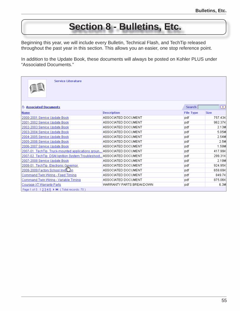
Section 8 - Bulletins, Etc.Beginning this year, we will include every Bulletin, Technical Flash, and TechTip released throughout the past year in this section. This allows you an easier, one stop reference point.
In addition to the Update Book, these documents will always be posted on Kohler PLUS under “Associated Documents.”
56
Bulletins, Etc.
251
Walker CH26
7/07DATE REVISEDDATE ISSUED
MODEL
NO.
PartsBulletin
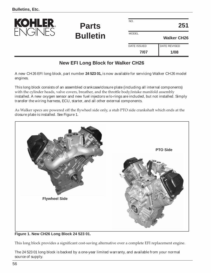
New EFI Long Block for Walker CH26
A new CH26 EFI long block, part number 24 523 01, is now available for servicing Walker CH26 model engines.
This long block consists of an assembled crankcase/closure plate (including all internal components)
installed. A new oxygen sensor and new fuel injectors w/o-rings are included, but not installed. Simply transfer the wiring harness, ECU, starter, and all other external components.
closure plate is installed. See Figure 1.
Figure 1. New CH26 Long Block 24 523 01.
The 24 523 01 long block is backed by a one-year limited warranty, and available from your normal source of supply.
Flywheel Side
PTO Side
1/08
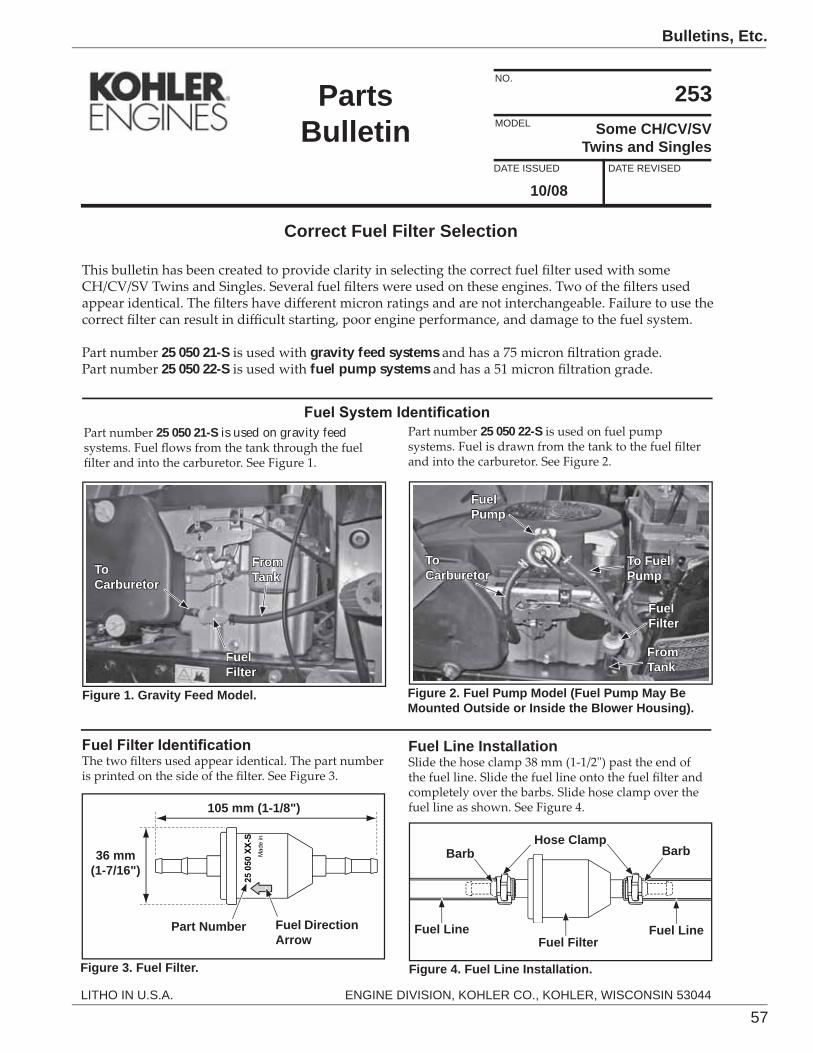
57
Bulletins, Etc.
253Some CH/CV/SV
Twins and Singles
10/08
Correct Fuel Filter Selection
25 050 21-S gravity feed systems25 050 22-S fuel pump systems
DATE REVISEDDATE ISSUED
MODEL
NO.
LITHO IN U.S.A. ENGINE DIVISION, KOHLER CO., KOHLER, WISCONSIN 53044
PartsBulletin
Figure 1. Gravity Feed Model.
25 050 21-S is used on gravity feed
FuelFilter
FuelPump
To Carburetor
FromTank
To Fuel Pump
Figure 2. Fuel Pump Model (Fuel Pump May Be Mounted Outside or Inside the Blower Housing).
FuelFilter
To Carburetor
FromTank
25 050 22-S
Mad
e in
25 0
50 X
X-S
Figure 3. Fuel Filter.
Fuel Direction Arrow
Part Number
36 mm (1-7/16")
105 mm (1-1/8")
Hose ClampBarbBarb
Fuel Line Fuel Line
Fuel Line Installation
Fuel Filter
Figure 4. Fuel Line Installation.
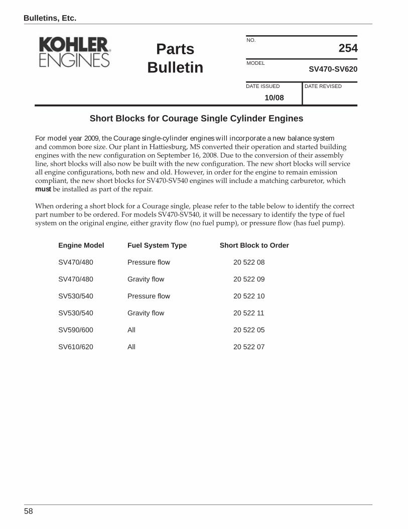
58
Bulletins, Etc.
254SV470-SV620
10/08
Short Blocks for Courage Single Cylinder Engines
For model year 2009, the Courage single-cylinder engines will incorporate a new balance system
must
DATE REVISEDDATE ISSUED
MODEL
NO.
PartsBulletin
Engine Model Fuel System Type Short Block to Order
SV470/480 Pressure 20 522 08
SV470/480 Gravity 20 522 09
SV530/540 Pressure 20 522 10
SV530/540 Gravity 20 522 11
SV590/600 All 20 522 05
SV610/620 All 20 522 07
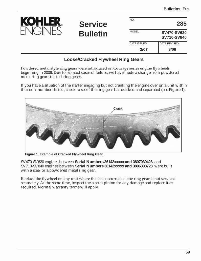
59
Bulletins, Etc.
Figure 1. Example of Cracked Flywheel Ring Gear.
3/08
SV470-SV620SV710-SV840
Loose/Cracked Flywheel Ring Gears
beginning in 2006. Due to isolated cases of failure, we have made a change from powdered metal ring gears to steel ring gears.
If you have a situation of the starter engaging but not cranking the engine over on a unit within the serial numbers listed, check to see if the ring gear has cracked and separated (see Figure 1).
285
3/07DATE REVISEDDATE ISSUED
MODEL
NO.
ServiceBulletin
SV470-SV620 engines between Serial Numbers 36142xxxxx and 3807030423, andSV710-SV840 engines between Serial Numbers 36142xxxxx and 3806308723, were built with a steel or a powdered metal ring gear.
separately. At the same time, inspect the starter pinion for any damage and replace it as required. Normal warranty terms will apply.
Crack
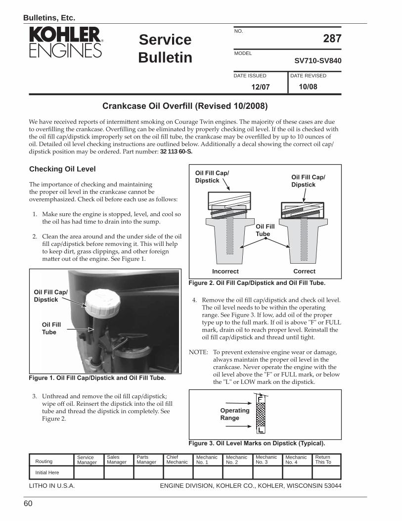
60
Bulletins, Etc.
ServiceManager
Initial Here
SalesManager
PartsManager
ChiefMechanic
MechanicNo. 1
MechanicNo. 2
MechanicNo. 3
MechanicNo. 4
ReturnThis ToRouting
SV710-SV840
32 113 60-S.
DATE REVISEDDATE ISSUED
MODEL
NO.
LITHO IN U.S.A. ENGINE DIVISION, KOHLER CO., KOHLER, WISCONSIN 53044
ServiceBulletin
Checking Oil Level
Oil Fill
Incorrect Correct
Operating
Oil Fill
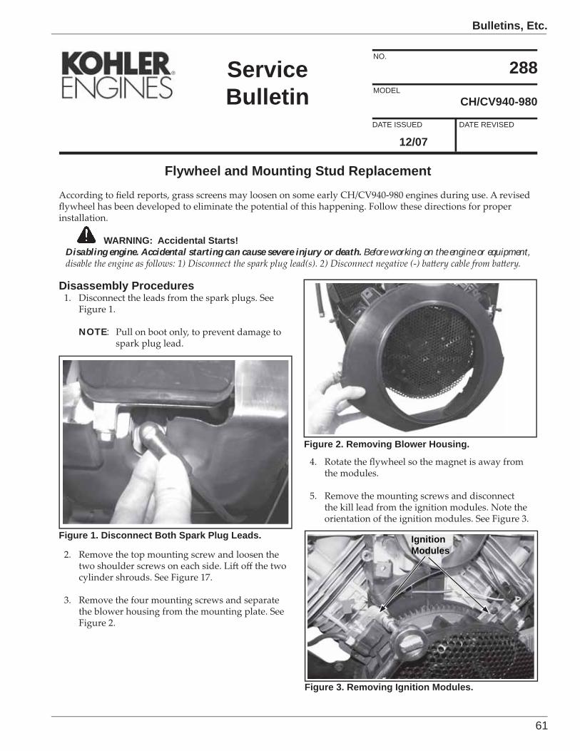
61
Bulletins, Etc.
6/94
CH/CV940-980
Flywheel and Mounting Stud Replacement
288
12/07DATE REVISEDDATE ISSUED
MODEL
NO.
ServiceBulletin
WARNING: Accidental Starts!Disabling engine. Accidental starting can cause severe injury or death. Before working on the engine or equipment,
Disassembly Procedures
NOTE:
Figure 1. Disconnect Both Spark Plug Leads.
Figure 2. Removing Blower Housing.
IgnitionModules
Figure 3. Removing Ignition Modules.
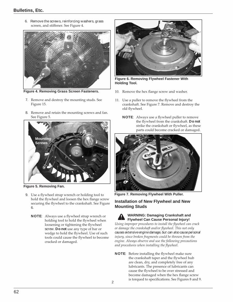
62
Bulletins, Etc.
2
6. Remove the screws, reinforcing washers, grass
Figure 4. Removing Grass Screen Fasteners.
7.
8.
MountingScrews
MountingScrews
Figure 5. Removing Fan.
9.
6.
NOTE:
screw. Do not
Figure 6. Removing Flywheel Fastener With Holding Tool.
NOTE:Do not
Figure 7. Removing Flywheel With Puller.
Installation of New Flywheel and New Mounting Studs
WARNING: Damaging Crankshaft and Flywheel Can Cause Personal Injury!
causes extensive engine damage, but can also cause personal
NOTE:
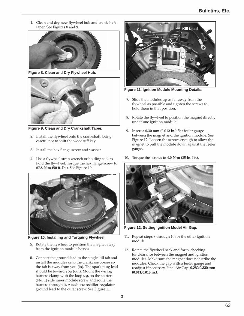
63
Bulletins, Etc.
3
Figure 9. Clean and Dry Crankshaft Taper.
Figure 8. Clean and Dry Flywheel Hub.
2.
3.
4.
Figure 10. Installing and Torquing Flywheel.
5.
6.
up
Clamp Kill Lead
Figure 11. Ignition Module Mounting Details.
7.
.
Feeler Gauge
Figure 12. Setting Ignition Model Air Gap.
0.280/0.330 mm .
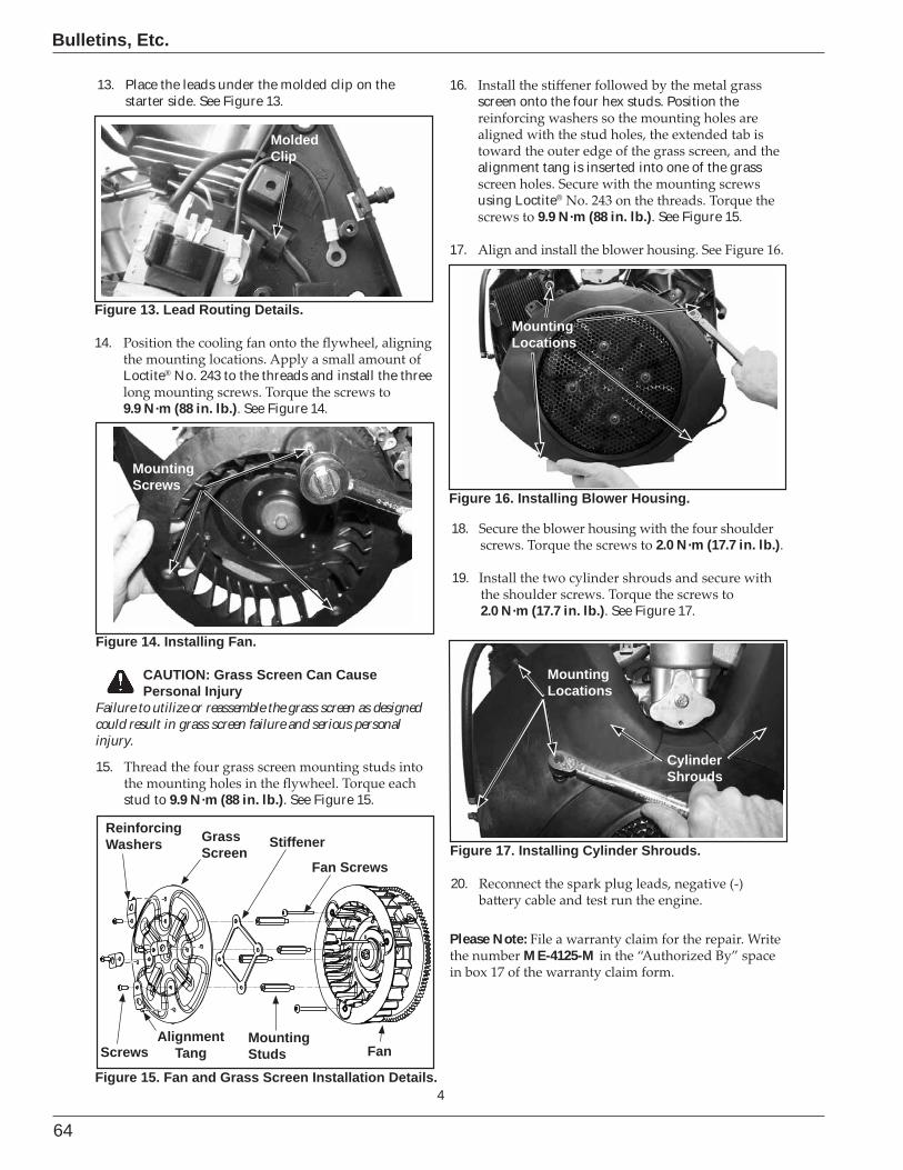
64
Bulletins, Etc.
4
Figure 13. Lead Routing Details.
14.
Loctite® No. 243 to the threads and install the three
9.9 N·m (88 in. lb.). See Figure 14.
MoldedClip
Figure 15. Fan and Grass Screen Installation Details.
Screws
Fan Screws
MountingStuds
StiffenerGrassScreen
ReinforcingWashers
Fan
MountingScrews
MountingScrews
Figure 14. Installing Fan.
15.
stud to 9.9 N·m (88 in. lb.). See Figure 15.
16.screen onto the four hex studs. Position the
alignment tang is inserted into one of the grass
using Loctite®
9.9 N·m (88 in. lb.). See Figure 15.
17.
AlignmentTang
MountingLocations
Figure 16. Installing Blower Housing.
18.2.0 N·m (17.7 in. lb.).
19.
2.0 N·m (17.7 in. lb.). See Figure 17.
MountingLocations
CylinderShrouds
Figure 17. Installing Cylinder Shrouds.
20.
CAUTION: Grass Screen Can Cause Personal Injury
Failure to utilize or reassemble the grass screen as designed could result in grass screen failure and serious personal injury.
13. Place the leads under the molded clip on the starter side. See Figure 13.
Please Note:ME-4125-M
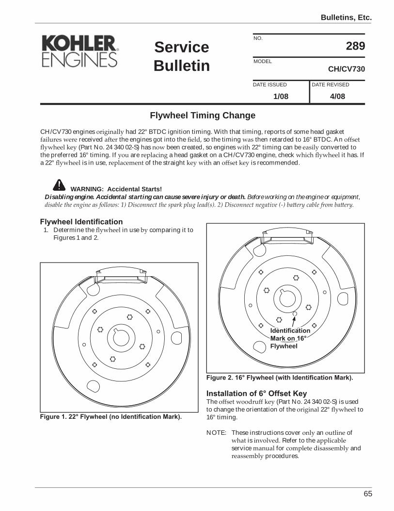
65
Bulletins, Etc.
CH/CV730
289
1/08DATE REVISEDDATE ISSUED
MODEL
NO.
ServiceBulletin
WARNING: Accidental Starts!Disabling engine. Accidental starting can cause severe injury or death. Before working on the engine or equipment,
1. Determine the in use comparing it toFigures 1 and 2.
Flywheel
Flywheel Timing ChangeCH/CV730 engines had 22° BTDC ignition timing. With that timing, reports of some head gasket
received the engines got into the so the timing then retarded to 16° BTDC. An(Part No. 24 340 02-S) has been created, so engines 22° timing can be converted to
the preferred 16° timing. If are a head gasket on a CH/CV730 engine, check it has. Ifa 22° is in use, of the straight an is recommended.
The (Part No. 24 340 02-S) is usedto change the orientation of the 22° to16° timing.
NOTE: These instructions cover an ofis Refer to the
service for andprocedures.
4/08
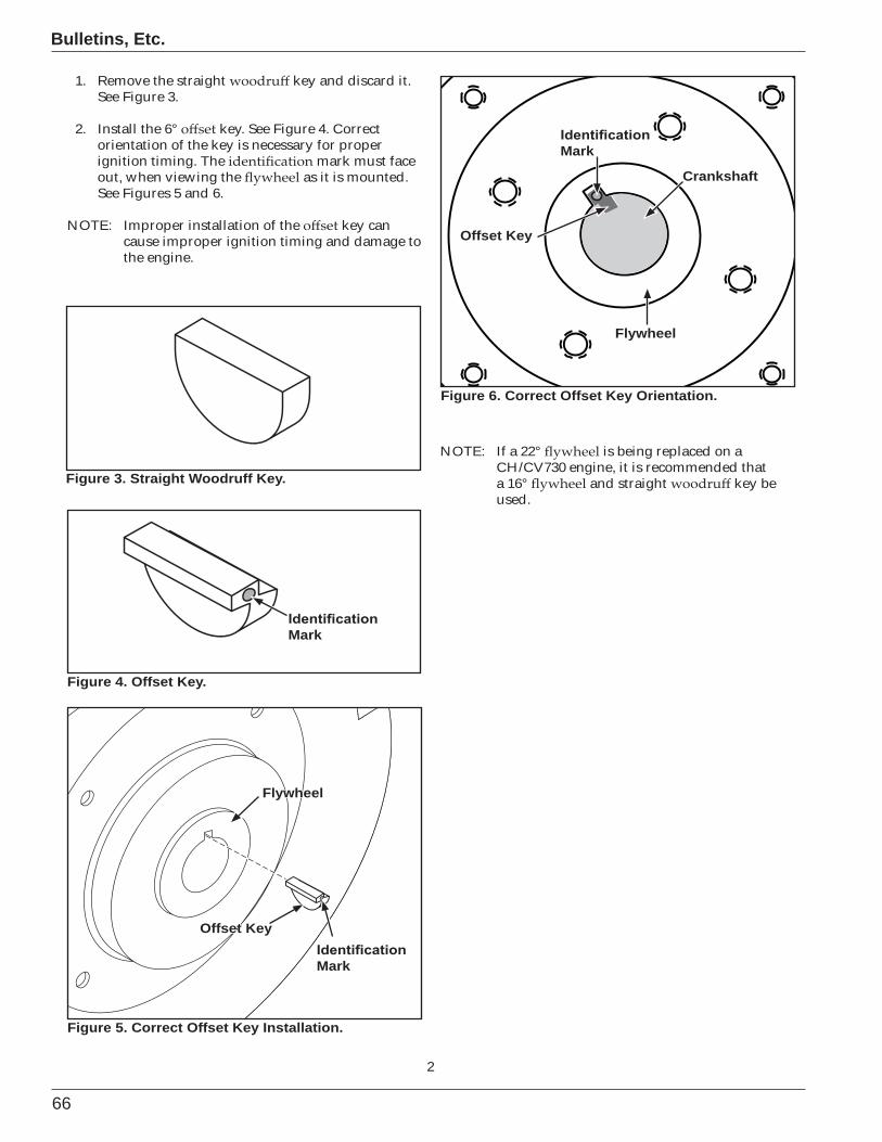
66
Bulletins, Etc.
2
Figure 6. Correct Offset Key Orientation.
Figure 5. Correct Offset Key Installation.
Figure 4. Offset Key.
Offset Key
Crankshaft
Flywheel
Offset Key
Flywheel
Figure 3. Straight Woodruff Key.
1. Remove the straight key and discard it.See Figure 3.
2. Install the 6° key. See Figure 4. Correctorientation of the key is necessary for properignition timing. The mark must faceout, when viewing the as it is mounted.See Figures 5 and 6.
NOTE: Improper installation of the key cancause improper ignition timing and damage tothe engine.
NOTE: If a 22° is being replaced on aCH/CV730 engine, it is recommended thata 16° and straight key beused.
Mark
Mark
Mark
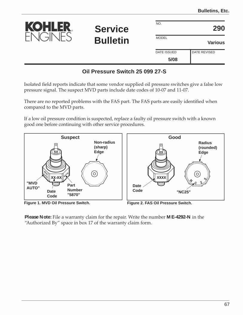
67
Bulletins, Etc.
6/94
Various
290
5/08DATE REVISEDDATE ISSUED
MODEL
NO.
ServiceBulletin
Oil Pressure Switch 25 099 27-S
XX-XX
MVDAUTO 5870
XXXX NC 2
5
DateCodeDate
Code
PartNumber"5870"
"MVDAUTO"
"NC25"
Radius(rounded)Edge
Non-radius(sharp)Edge
Figure 1. MVD Oil Pressure Switch. Figure 2. FAS Oil Pressure Switch.
Please Note: ME-4292-N
Suspect Good
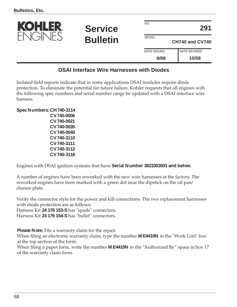
68
Bulletins, Etc.
10/08
CH740 and CV740
291
9/08DATE REVISEDDATE ISSUED
MODEL
NO.
ServiceBulletin
DSAI Interface Wire Harnesses with Diodes
Spec Numbers: CH740-3114CV740-0006CV740-0021CV740-0035CV740-0040CV740-3110CV740-3111CV740-3112CV740-3118
Serial Number 3823303501 and below
24 176 153-S24 176 154-S
Please Note:ME4410N
ME4410N
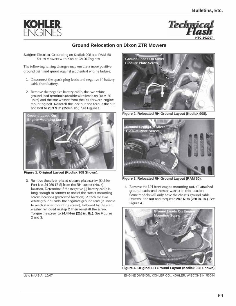
69
Bulletins, Etc.
1 ENGINE DIVISION, KOHLER CO., KOHLER, WISCONSIN 53044
Ground Relocation on Dixon ZTR Mowers
Figure 1. Original Layout (Kodiak 908 Shown).
3. Remove the silver-plated closure plate screw (KohlerPart No. 24 086 17-S) from the RH corner (No. 4)
long enough to connect to one of the starter mounting
white ground leads, the negative ground lead (if unable
washer removed in step 2, then reinstall the screw.Torque the screw to 24.4 N·m (216 in. lb.). See Figures2 and 3.
Figure 3. Relocated RH Ground Layout (RAM 50).
4.ground leads, and the star washer in this location.
Reinstall the nut and torque to 28.3 N·m (250 in. lb.). SeeFigure 4.
Ground Leads On Engine Mounting Screw
Litho In U.S.A. 10/07
Figure 2. Relocated RH Ground Layout (Kodiak 908).
Ground Leads On SilverClosure Plate Screw
Ground Leads On SilverClosure Plate Screw
Subject: Electrical Grounding on Kodiak 908 and RAM 50Series Mowers with Kohler CV20 Engines
ground path and guard against a potential engine failure.
1.
2.ground lead terminals (double wire leads on RAM 50units) and the star washer from the RH forward enginemounting bolt. Reinstall the lock nut and torque the nutand bolt to 28.3 N·m (250 in. lb.). See Figure 1.
Figure 4. Original LH Ground Layout (Kodiak 908 Shown).
Ground Leads On Engine Mounting Screw
HTC-102007
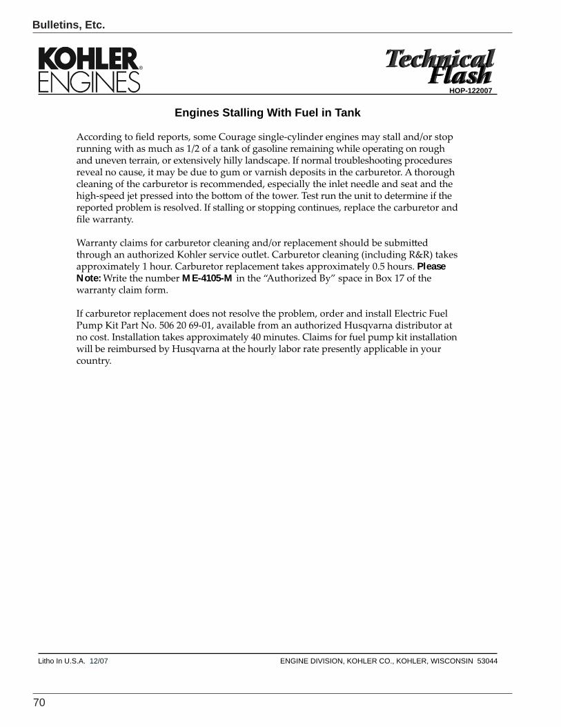
70
Bulletins, Etc.
1Litho In U.S.A. 12/07 ENGINE DIVISION, KOHLER CO., KOHLER, WISCONSIN 53044
Engines Stalling With Fuel in Tank
PleaseNote: ME-4105-M
HOP-122007
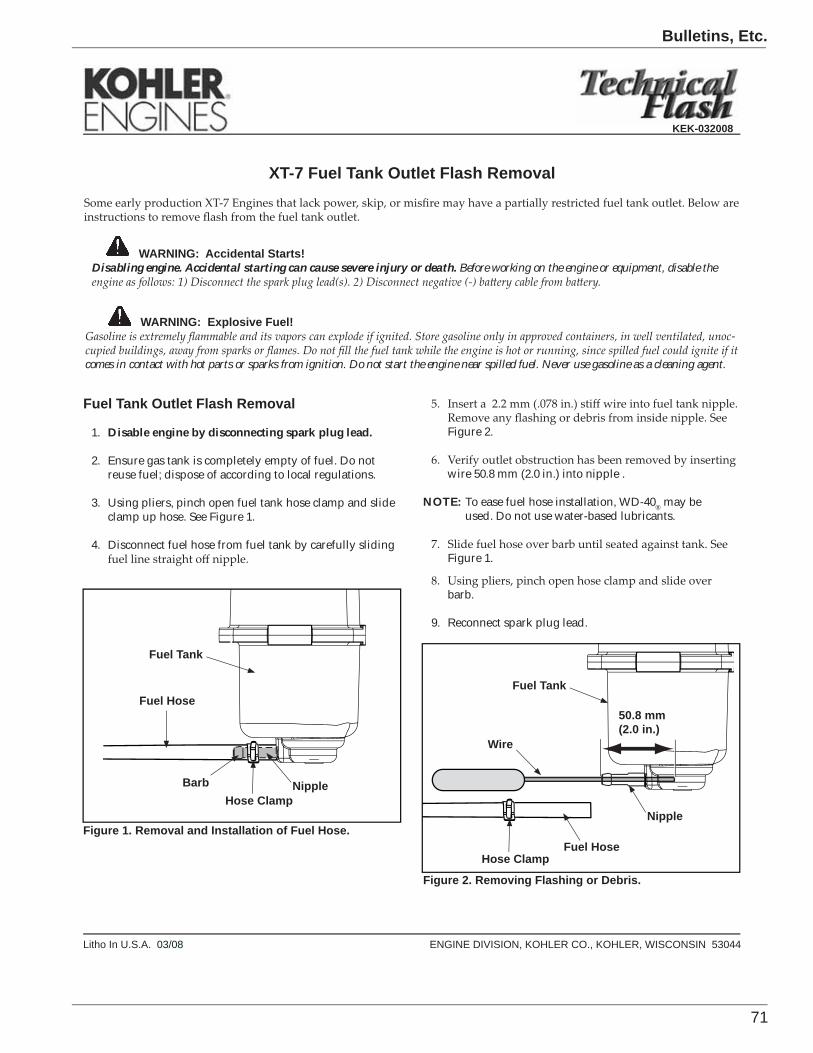
71
Bulletins, Etc.
1Litho In U.S.A. 03/08 ENGINE DIVISION, KOHLER CO., KOHLER, WISCONSIN 53044
KEK-032008
WARNING: Accidental Starts!Disabling engine. Accidental starting can cause severe injury or death. Before working on the engine or equipment, disable the
Fuel Tank Outlet Flash Removal
1. Disable engine by disconnecting spark plug lead.
2. Ensure gas tank is completely empty of fuel. Do notreuse fuel; dispose of according to local regulations.
3. Using pliers, pinch open fuel tank hose clamp and slideclamp up hose. See Figure 1.
4. Disconnect fuel hose from fuel tank by carefully sliding
XT-7 Fuel Tank Outlet Flash Removal
WARNING: Explosive Fuel!-
comes in contact with hot parts or sparks from ignition. Do not start the engine near spilled fuel. Never use gasoline as a cleaning agent.
Hose Clamp
Figure 1. Removal and Installation of Fuel Hose.
Fuel Tank
Fuel Hose
Barb
Figure 2. Removing Flashing or Debris.
Fuel Tank
Wire
Figure 2.
wire 50.8 mm (2.0 in.) into nipple .
NOTE: To ease fuel hose installation, WD-40® may be used. Do not use water-based lubricants.
Figure 1.
barb.
9. Reconnect spark plug lead.
Nipple
Nipple
50.8 mm(2.0 in.)
Hose ClampFuel Hose
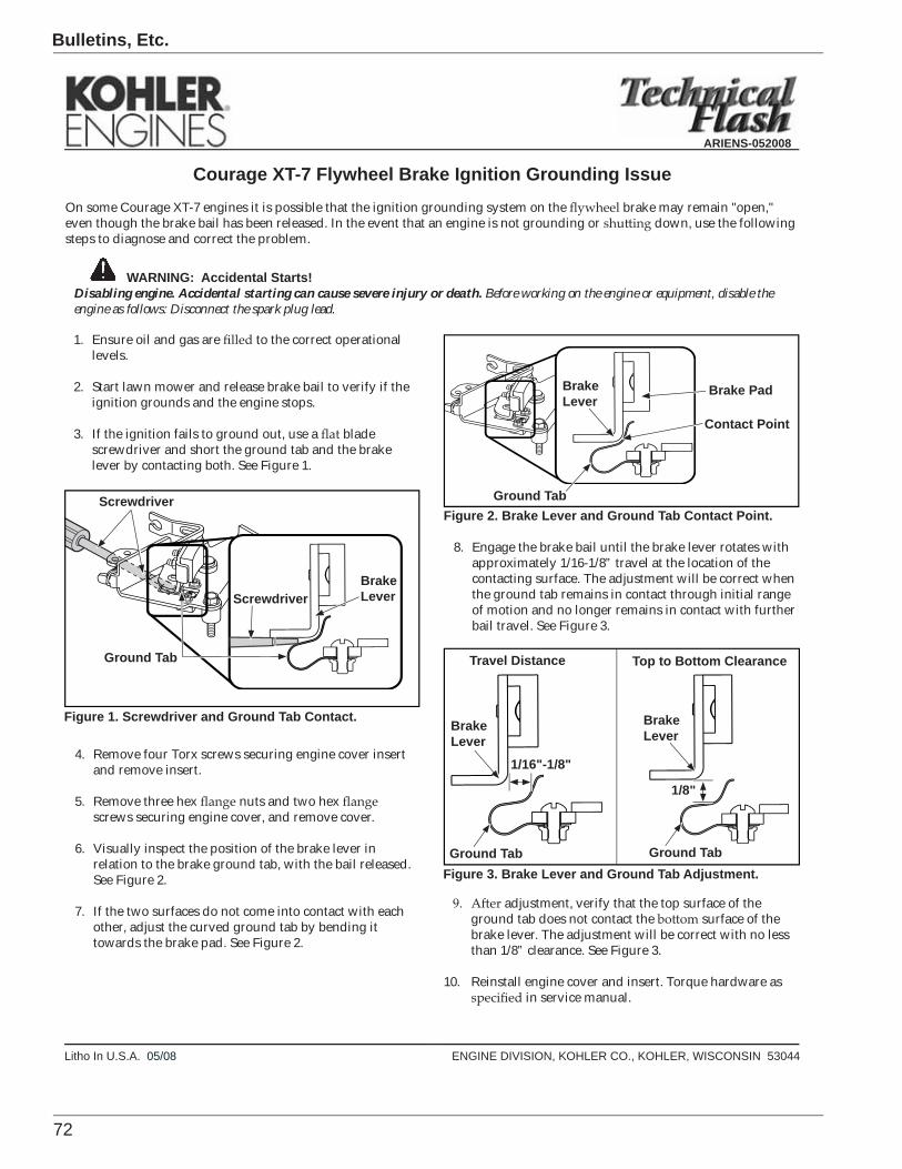
72
Bulletins, Etc.
1Litho In U.S.A. 05/08 ENGINE DIVISION, KOHLER CO., KOHLER, WISCONSIN 53044
ARIENS-052008
WARNING: Accidental Starts!Disabling engine. Accidental starting can cause severe injury or death. Before working on the engine or equipment, disable the engine as follows: Disconnect the spark plug lead.
1. Ensure oil and gas are to the correct operationallevels.
2. Start lawn mower and release brake bail to verify if theignition grounds and the engine stops.
3. If the ignition fails to ground out, use a bladescrewdriver and short the ground tab and the brakelever by contacting both. See Figure 1.
Courage XT-7 Flywheel Brake Ignition Grounding IssueOn some Courage XT-7 engines it is possible that the ignition grounding system on the brake may remain "open,"even though the brake bail has been released. In the event that an engine is not grounding or down, use the followingsteps to diagnose and correct the problem.
Figure 1. Screwdriver and Ground Tab Contact.
BrakeLever
Screwdriver
Ground Tab
4. Remove four Torx screws securing engine cover insertand remove insert.
5. Remove three hex nuts and two hexscrews securing engine cover, and remove cover.
6. Visually inspect the position of the brake lever inrelation to the brake ground tab, with the bail released.See Figure 2.
7. If the two surfaces do not come into contact with eachother, adjust the curved ground tab by bending ittowards the brake pad. See Figure 2.
8. Engage the brake bail until the brake lever rotates withapproximately 1/16-1/8” travel at the location of thecontacting surface. The adjustment will be correct whenthe ground tab remains in contact through initial rangeof motion and no longer remains in contact with furtherbail travel. See Figure 3.
Figure 2. Brake Lever and Ground Tab Contact Point.
BrakeLever
Contact Point
Ground Tab
Figure 3. Brake Lever and Ground Tab Adjustment.Ground Tab
Brake Pad
adjustment, verify that the top surface of theground tab does not contact the surface of thebrake lever. The adjustment will be correct with no lessthan 1/8” clearance. See Figure 3.
10. Reinstall engine cover and insert. Torque hardware asin service manual.
Screwdriver
BrakeLever
1/16"-1/8"
BrakeLever
1/8"
Ground Tab
Travel Distance Top to Bottom Clearance
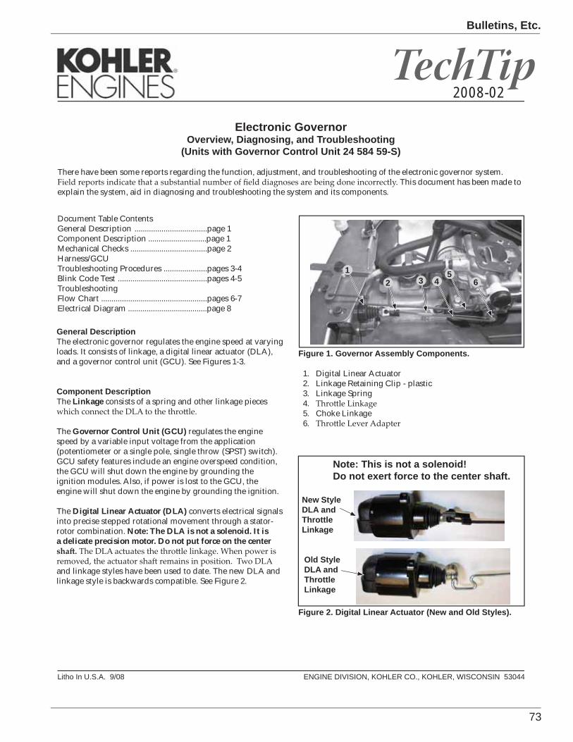
73
Bulletins, Etc.
TechTip
Litho In U.S.A. 9/08 ENGINE DIVISION, KOHLER CO., KOHLER, WISCONSIN 53044
Electronic GovernorOverview, Diagnosing, and Troubleshooting
(Units with Governor Control Unit 24 584 59-S)
There have been some reports regarding the function, adjustment, and troubleshooting of the electronic governor system. . This document has been made to
explain the system, aid in diagnosing and troubleshooting the system and its components.
2008-02
General DescriptionThe electronic governor regulates the engine speed at varying loads. It consists of linkage, a digital linear actuator (DLA), and a governor control unit (GCU). See Figures 1-3.
Component DescriptionThe Linkage consists of a spring and other linkage pieces
The Governor Control Unit (GCU) regulates the engine speed by a variable input voltage from the application (potentiometer or a single pole, single throw (SPST) switch). GCU safety features include an engine overspeed condition, the GCU will shut down the engine by grounding the ignition modules. Also, if power is lost to the GCU, the engine will shut down the engine by grounding the ignition.
The Digital Linear Actuator (DLA) converts electrical signals into precise stepped rotational movement through a stator-rotor combination. Note: The DLA is not a solenoid. It is a delicate precision motor. Do not put force on the center
and linkage styles have been used to date. The new DLA and linkage style is backwards compatible. See Figure 2.
Figure 1. Governor Assembly Components.
1. Digital Linear Actuator2. Linkage Retaining Clip - plastic3. Linkage Spring4.5. Choke Linkage6.
New Style DLA and ThrottleLinkage
Old Style DLA and ThrottleLinkage
Figure 2. Digital Linear Actuator (New and Old Styles).
12 3
56
Note: This is not a solenoid!Do not exert force to the center shaft.
4
Document Table ContentsGeneral Description ...................................page 1Component Description ............................page 1Mechanical Checks .....................................page 2Harness/GCUTroubleshooting Procedures .....................pages 3-4Blink Code Test ...........................................pages 4-5Troubleshooting Flow Chart ...................................................pages 6-7Electrical Diagram ......................................page 8

74
Bulletins, Etc.
2
Figure 3. Governor Control Unit Locations.
Governor Control Unit
Governor Control Unit
Actuator
Clevis Shaft
Rubber Boot
Figure 5. Exploded View of Clevis Shaft.
Keyway
Keys
Clevis
Mounting Holes
Mechanical Checks The DLA must be in the fully retracted position during
not be achieved if the DLA is partially extended when assembled. Loosen the two DLA mounting plate screws
linkage centered in the U-Clip or secured with a retaining
the mounting plate screws to 2.5 N·m (22 in. lb.).
MountingPlateScrews
Figure 4. Throttle Plate Mounting Screws.
the actuator reinstall as follows:
1. Disconnect linkage and remove the Digital Linear Actuator (DLA) from the control assembly. See Figure 1.
2.
3.
4.
mounting holes.
NOTE:contact with the keyway will damage the keyway or the actuator.
repeat the previous step.
6. Install DLA into the control assembly and connect linkage. See Figure 1.
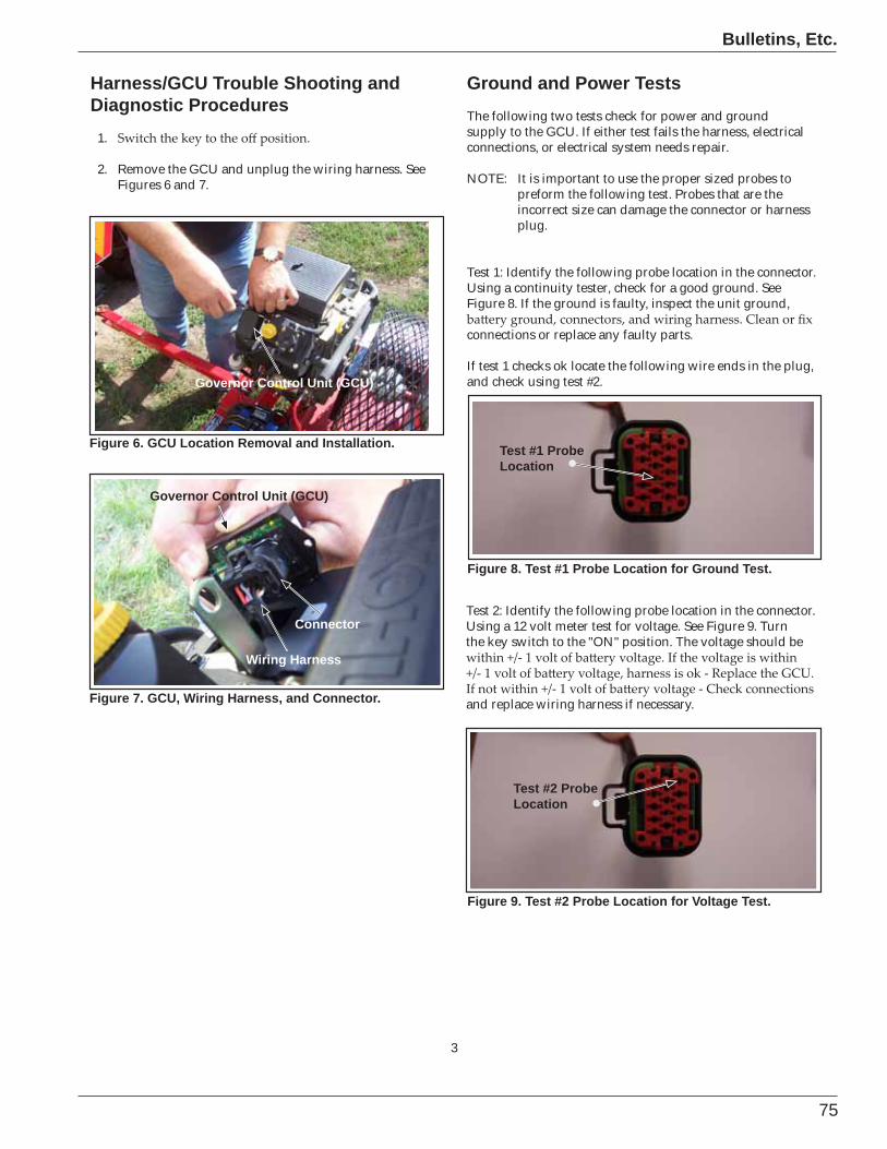
75
Bulletins, Etc.
3
Harness/GCU Trouble Shooting and Diagnostic Procedures
1.
2. Remove the GCU and unplug the wiring harness. See Figures 6 and 7.
Figure 7. GCU, Wiring Harness, and Connector.
Governor Control Unit (GCU)
Connector
Figure 6. GCU Location Removal and Installation.
Governor Control Unit (GCU)
Wiring Harness
Test #1 Probe Location
Figure 8. Test #1 Probe Location for Ground Test.
Figure 9. Test #2 Probe Location for Voltage Test.
Test #2 Probe Location
Ground and Power TestsThe following two tests check for power and ground supply to the GCU. If either test fails the harness, electrical connections, or electrical system needs repair.
NOTE: It is important to use the proper sized probes to preform the following test. Probes that are the incorrect size can damage the connector or harness plug.
Test 1: Identify the following probe location in the connector.Using a continuity tester, check for a good ground. See Figure 8. If the ground is faulty, inspect the unit ground,
connections or replace any faulty parts.
If test 1 checks ok locate the following wire ends in the plug, and check using test #2.
Test 2: Identify the following probe location in the connector.Using a 12 volt meter test for voltage. See Figure 9. Turn the key switch to the "ON" position. The voltage should be
and replace wiring harness if necessary.
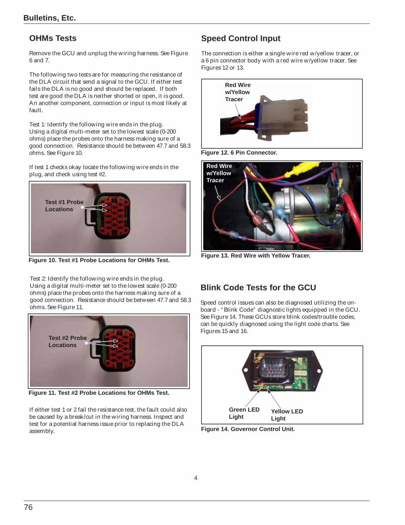
76
Bulletins, Etc.
4
OHMs TestsRemove the GCU and unplug the wiring harness. See Figure 6 and 7.
The following two tests are for measuring the resistance of the DLA circuit that send a signal to the GCU. If either test fails the DLA is no good and should be replaced. If both test are good the DLA is neither shorted or open, it is good. An another component, connection or input is most likely at fault.
Test 1: Identify the following wire ends in the plug.Using a digital multi-meter set to the lowest scale (0-200 ohms) place the probes onto the harness making sure of a good connection. Resistance should be between 47.7 and 58.3 ohms. See Figure 10.
If test 1 checks okay locate the following wire ends in the plug, and check using test #2.
Test #1 Probe Locations
Test #2 Probe Locations
Figure 10. Test #1 Probe Locations for OHMs Test.
Figure 11. Test #2 Probe Locations for OHMs Test.
Green LEDLight
Yellow LEDLight
Figure 14. Governor Control Unit.
Blink Code Tests for the GCUSpeed control issues can also be diagnosed utilizing the on-board - “Blink Code” diagnostic lights equipped in the GCU. See Figure 14. These GCUs store blink codes/trouble codes, can be quickly diagnosed using the light code charts. See Figures 15 and 16.
Figure 12. 6 Pin Connector.
Figure 13. Red Wire with Yellow Tracer.
Red Wire w/Yellow Tracer
Test 2: Identify the following wire ends in the plug.Using a digital multi-meter set to the lowest scale (0-200 ohms) place the probes onto the harness making sure of a good connection. Resistance should be between 47.7 and 58.3 ohms. See Figure 11.
If either test 1 or 2 fail the resistance test, the fault could also be caused by a break/cut in the wiring harness. Inspect and test for a potential harness issue prior to replacing the DLA assembly.
Red Wire w/Yellow Tracer
Speed Control InputThe connection is either a single wire red w/yellow tracer, or a 6 pin connector body with a red wire w/yellow tracer. See Figures 12 or 13.
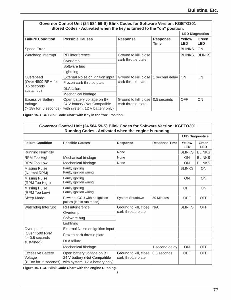
77
Bulletins, Etc.
5Figure 16. GCU Blink Code Chart with the engine Running.
Governor Control Unit (24 584 59-S) Blink Codes for Software Version: KGETO301Stored Codes - Activated when the key is turned to the "on" position.
LED DiagnosticsFailure Condition Possible Causes Response Response
TimeYellow LED
GreenLED
Speed Error BLINKS ONWatchdog Interrupt RFI interference Ground to kill, close
carb throttle plateBLINKS BLINKS
OvertempSoftware bugLightning
Overspeed(Over 4500 RPM for 0.5 seconds sustained)
External Noise on ignition input Ground to kill, close carb throttle plate
1 second delay ON ONFrozen carb throttle plateDLA failureMechanical bindage
Excessive Battery Voltage(> 18v for .5 seconds)
Open battery voltage on B+ 24 V battery (Not Compatible with system, 12 V battery only)
Ground to kill, close carb throttle plate
0.5 seconds OFF ON
Governor Control Unit (24 584 59-S) Blink Codes for Software Version: KGETO301Running Codes - Activated when the engine is running.
LED Diagnostics
Failure Condition Possible Causes Response Response Time Yellow LED
GreenLED
Running Normally None BLINKS BLINKSRPM Too High Mechanical bindage None ON BLINKSRPM Too Low Mechanical bindage None ON BLINKSMissing Pulse(Normal RPM)
Faulty ignitingFaulty ignition wiring
BLINKS ON
Missing Pulse(RPM Too High)
Faulty ignitingFaulty ignition wiring
ON ON
Missing Pulse(RPM Too Low)
Faulty ignitingFaulty ignition wiring
OFF ON
Sleep Mode Power at GCU with no ignition pulses (left in run mode)
System Shutdown 30 Minutes OFF OFF
Watchdog Interrupt RFI interference Ground to kill, close carb throttle plate
N/A BLINKS OFFOvertempSoftware bugLightning
Overspeed(Over 4500 RPM for 0.5 seconds sustained)
External Noise on ignition inputFrozen carb throttle plateDLA failureMechanical bindage 1 second delay ON OFF
Excessive Battery Voltage(> 18v for .5 seconds)
Open battery voltage on B+ 24 V battery (Not Compatible with system, 12 V battery only)
Ground to kill, close carb throttle plate
0.5 seconds OFF OFF
Figure 15. GCU Blink Code Chart with Key in the "on" Position.
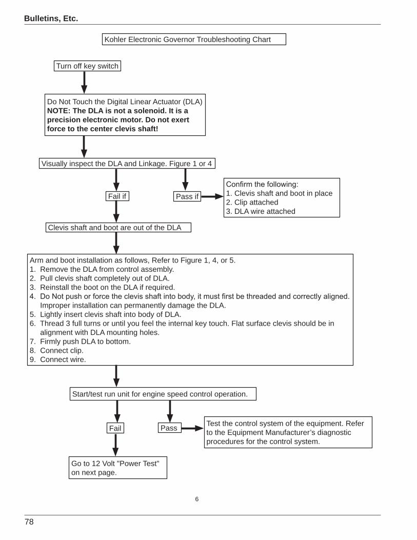
78
Bulletins, Etc.
6
Kohler Electronic Governor Troubleshooting Chart
Turn off key switch
Do Not Touch the Digital Linear Actuator (DLA) NOTE: The DLA is not a solenoid. It is a precision electronic motor. Do not exert force to the center clevis shaft!
Visually inspect the DLA and Linkage. Figure 1 or 4
Arm and boot installation as follows, Refer to Figure 1, 4, or 5.1. Remove the DLA from control assembly.2. Pull clevis shaft completely out of DLA.3. Reinstall the boot on the DLA if required.
Improper installation can permanently damage the DLA.5. Lightly insert clevis shaft into body of DLA.6. Thread 3 full turns or until you feel the internal key touch. Flat surface clevis should be in alignment with DLA mounting holes.7. Firmly push DLA to bottom.8. Connect clip.9. Connect wire.
1. Clevis shaft and boot in place2. Clip attached 3. DLA wire attached
Fail if Pass if
Fail Pass
Clevis shaft and boot are out of the DLA
Test the control system of the equipment. Refer to the Equipment Manufacturer’s diagnostic procedures for the control system.
Go to 12 Volt "Power Test" on next page.
Start/test run unit for engine speed control operation.
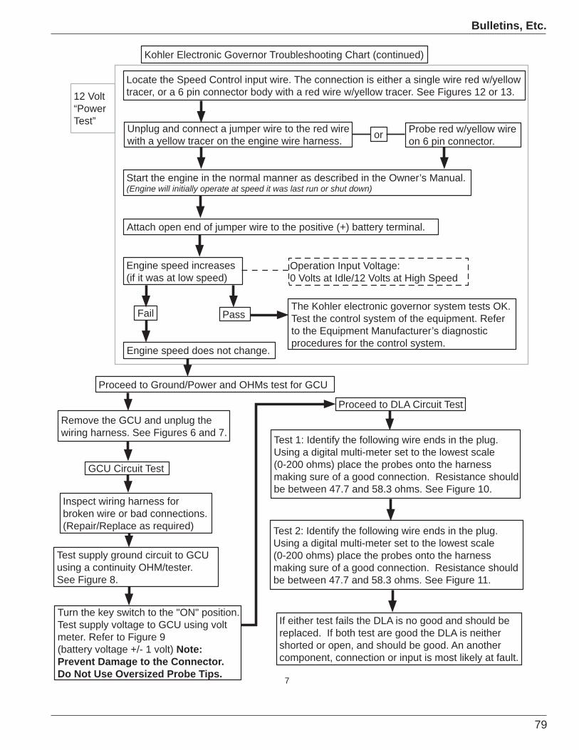
79
Bulletins, Etc.
7
Test 1: Identify the following wire ends in the plug. Using a digital multi-meter set to the lowest scale (0-200 ohms) place the probes onto the harness making sure of a good connection. Resistance should be between 47.7 and 58.3 ohms. See Figure 10.
If either test fails the DLA is no good and should be replaced. If both test are good the DLA is neither shorted or open, and should be good. An another component, connection or input is most likely at fault.
GCU Circuit Test
Remove the GCU and unplug the wiring harness. See Figures 6 and 7.
Test 2: Identify the following wire ends in the plug. Using a digital multi-meter set to the lowest scale(0-200 ohms) place the probes onto the harness making sure of a good connection. Resistance should be between 47.7 and 58.3 ohms. See Figure 11.
Inspect wiring harness for broken wire or bad connections. (Repair/Replace as required)
Test supply ground circuit to GCU using a continuity OHM/tester. See Figure 8.
Locate the Speed Control input wire. The connection is either a single wire red w/yellow tracer, or a 6 pin connector body with a red wire w/yellow tracer. See Figures 12 or 13.
Unplug and connect a jumper wire to the red wire with a yellow tracer on the engine wire harness.
Start the engine in the normal manner as described in the Owner’s Manual.(Engine will initially operate at speed it was last run or shut down)
Attach open end of jumper wire to the positive (+) battery terminal.
Engine speed increases (if it was at low speed)
Engine speed does not change.
The Kohler electronic governor system tests OK. Test the control system of the equipment. Refer to the Equipment Manufacturer’s diagnostic procedures for the control system.
Proceed to Ground/Power and OHMs test for GCU
12 Volt “PowerTest”
Probe red w/yellow wire on 6 pin connector.or
Fail Pass
Proceed to DLA Circuit Test
Operation Input Voltage:0 Volts at Idle/12 Volts at High Speed
Kohler Electronic Governor Troubleshooting Chart (continued)
Turn the key switch to the "ON" position. Test supply voltage to GCU using volt meter. Refer to Figure 9 (battery voltage +/- 1 volt) Note:Prevent Damage to the Connector. Do Not Use Oversized Probe Tips.
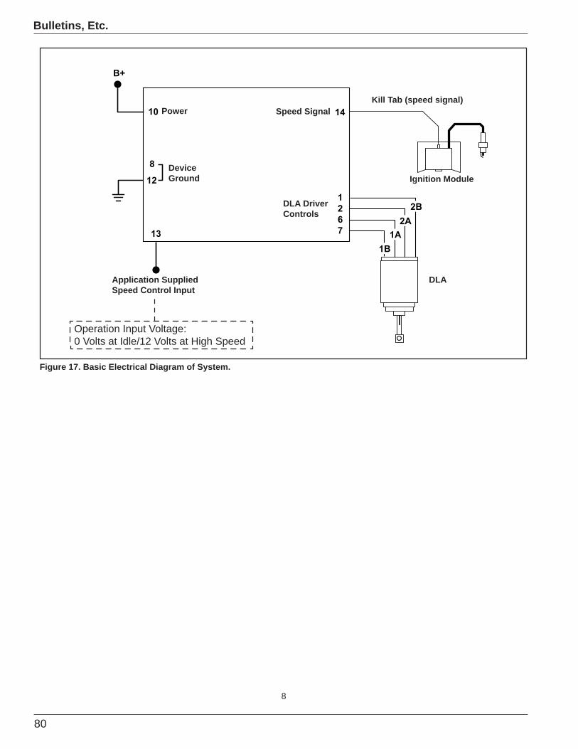
80
Bulletins, Etc.
8
B+
10
8
12
13
14
1267
1B1A
2A2B
Application Supplied Speed Control Input
Figure 17. Basic Electrical Diagram of System.
Operation Input Voltage: 0 Volts at Idle/12 Volts at High Speed
DeviceGround
Power Speed SignalKill Tab (speed signal)
DLA DriverControls
DLA
Ignition Module
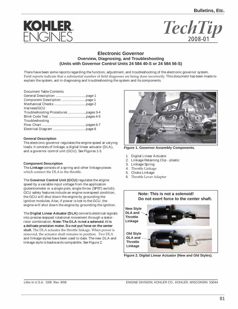
81
Bulletins, Etc.
TechTip
Litho In U.S.A. 2/08 Rev. 9/08 ENGINE DIVISION, KOHLER CO., KOHLER, WISCONSIN 53044
Electronic GovernorOverview, Diagnosing, and Troubleshooting
(Units with Governor Control Units 24 584 40-S or 24 584 56-S)
There have been some reports regarding the function, adjustment, and troubleshooting of the electronic governor system. . This document has been made to
explain the system, aid in diagnosing and troubleshooting the system and its components.
2008-01
General DescriptionThe electronic governor regulates the engine speed at varying loads. It consists of linkage, a digital linear actuator (DLA), and a governor control unit (GCU). See Figures 1-3.
Component DescriptionThe Linkage consists of a spring and other linkage pieces
The Governor Control Unit (GCU) regulates the engine speed by a variable input voltage from the application (potentiometer or a single pole, single throw (SPST) switch). GCU safety features include an engine overspeed condition, the GCU will shut down the engine by grounding the ignition modules. Also, if power is lost to the GCU, the engine will shut down the engine by grounding the ignition.
The Digital Linear Actuator (DLA) converts electrical signals into precise stepped rotational movement through a stator-rotor combination. Note: The DLA is not a solenoid. It is a delicate precision motor. Do not put force on the center
and linkage styles have been used to date. The new DLA and linkage style is backwards compatible. See Figure 2.
Figure 1. Governor Assembly Components.
1. Digital Linear Actuator2. Linkage Retaining Clip - plastic3. Linkage Spring4.5. Choke Linkage6.
New Style DLA and ThrottleLinkage
Old Style DLA and ThrottleLinkage
Figure 2. Digital Linear Actuator (New and Old Styles).
12 3
56
Note: This is not a solenoid!Do not exert force to the center shaft.
4
Document Table ContentsGeneral Description ...................................page 1 Component Description ............................page 1Mechanical Checks .....................................page 2Harness/GCUTroubleshooting Procedures .....................pages 3-4Blink Code Test ...........................................pages 4-5Troubleshooting Flow Chart ...................................................pages 6-7Electrical Diagram ......................................page 8
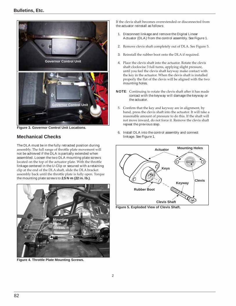
82
Bulletins, Etc.
2
Figure 3. Governor Control Unit Locations.
Governor Control Unit
Governor Control Unit
Actuator
Clevis Shaft
Rubber Boot
Figure 5. Exploded View of Clevis Shaft.
Keyway
Keys
Clevis
Mounting Holes
Mechanical Checks The DLA must be in the fully retracted position during
not be achieved if the DLA is partially extended when assembled. Loosen the two DLA mounting plate screws
linkage centered in the U-Clip or secured with a retaining
the mounting plate screws to 2.5 N·m (22 in. lb.).
MountingPlateScrews
Figure 4. Throttle Plate Mounting Screws.
the actuator reinstall as follows:
1. Disconnect linkage and remove the Digital Linear Actuator (DLA) from the control assembly. See Figure 1.
2.
3.
4.
mounting holes.
NOTE:contact with the keyway will damage the keyway or the actuator.
repeat the previous step.
6. Install DLA into the control assembly and connect linkage. See Figure 1.

83
Bulletins, Etc.
3
Harness/GCU Trouble Shooting and Diagnostic Procedures
1.
2. Remove the GCU and unplug the wiring harness. See Figures 6 and 7.
Figure 7. GCU, Wiring Harness, and Connector.
Governor Control Unit (GCU)
Connector
Figure 6. GCU Location Removal and Installation.
Governor Control Unit (GCU)
Wiring Harness
Test #1 Probe Location
Figure 8. Test #1 Probe Location for Ground Test.
Figure 9. Test #2 Probe Location for Voltage Test.
Test #2 Probe Location
Ground and Power TestsThe following two tests check for power and ground supply to the GCU. If either test fails the harness, electrical connections, or electrical system needs repair.
NOTE: It is important to use the proper sized probes to preform the following test. Probes that are the incorrect size can damage the connector or harness plug.
Test 1: Identify the following probe location in the connector.Using a continuity tester, check for a good ground. See Figure 8. If the ground is faulty, inspect the unit ground,
connections or replace any faulty parts.
If test 1 checks ok locate the following wire ends in the plug, and check using test #2.
Test 2: Identify the following probe location in the connector.Using a 12 volt meter test for voltage. See Figure 9. The
- Check connections and replace wiring harness if necessary.
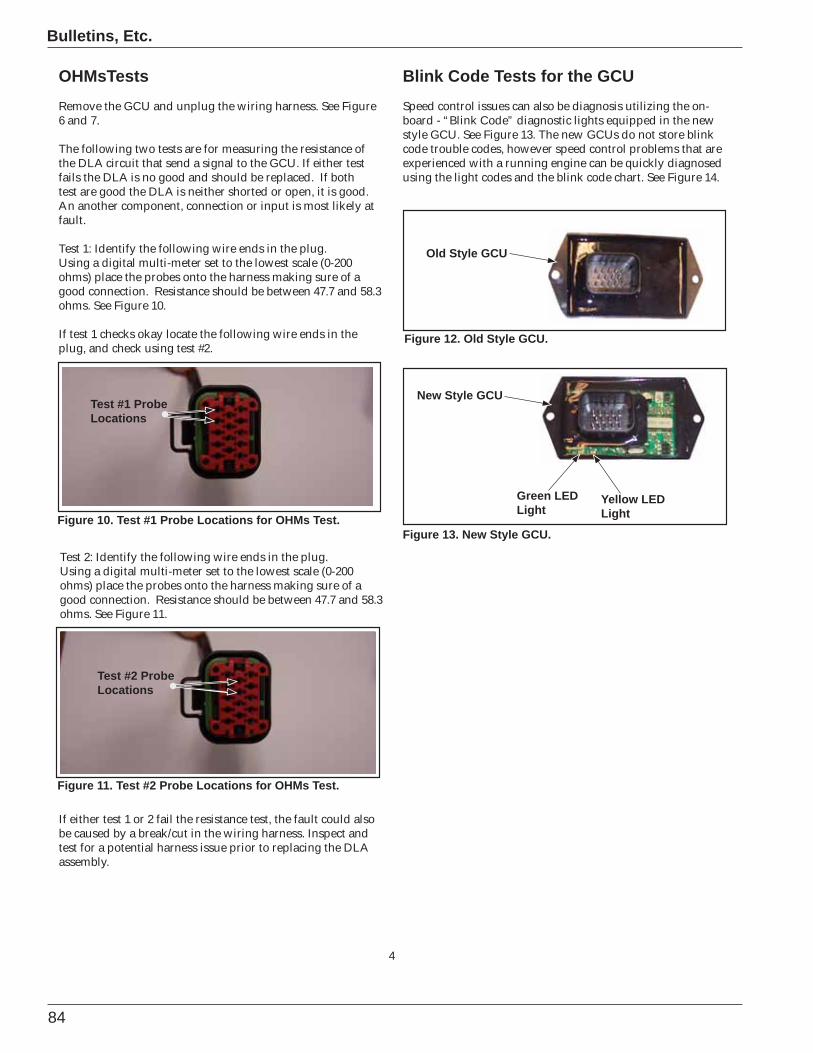
84
Bulletins, Etc.
4
OHMsTestsRemove the GCU and unplug the wiring harness. See Figure 6 and 7.
The following two tests are for measuring the resistance of the DLA circuit that send a signal to the GCU. If either test fails the DLA is no good and should be replaced. If both test are good the DLA is neither shorted or open, it is good. An another component, connection or input is most likely at fault.
Test 1: Identify the following wire ends in the plug.Using a digital multi-meter set to the lowest scale (0-200 ohms) place the probes onto the harness making sure of a good connection. Resistance should be between 47.7 and 58.3 ohms. See Figure 10.
If test 1 checks okay locate the following wire ends in the plug, and check using test #2.
Test #1 Probe Locations
Test #2 Probe Locations
Figure 10. Test #1 Probe Locations for OHMs Test.
Figure 11. Test #2 Probe Locations for OHMs Test.
Old Style GCU
New Style GCU
Green LEDLight
Yellow LEDLight
Figure 12. Old Style GCU.
Figure 13. New Style GCU.
Blink Code Tests for the GCUSpeed control issues can also be diagnosis utilizing the on-board - “Blink Code” diagnostic lights equipped in the new style GCU. See Figure 13. The new GCUs do not store blink code trouble codes, however speed control problems that are experienced with a running engine can be quickly diagnosed using the light codes and the blink code chart. See Figure 14.
Test 2: Identify the following wire ends in the plug.Using a digital multi-meter set to the lowest scale (0-200 ohms) place the probes onto the harness making sure of a good connection. Resistance should be between 47.7 and 58.3 ohms. See Figure 11.
If either test 1 or 2 fail the resistance test, the fault could also be caused by a break/cut in the wiring harness. Inspect and test for a potential harness issue prior to replacing the DLA assembly.
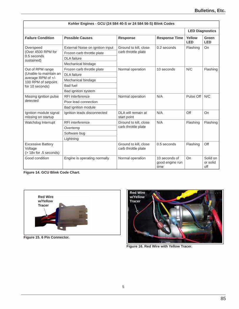
85
Bulletins, Etc.
5
Kohler Engines - GCU (24 584 40-S or 24 584 56-S) Blink Codes
LED Diagnostics
Failure Condition Possible Causes Response Response Time Yellow LED
GreenLED
Overspeed(Over 4500 RPM for 0.5 seconds sustained)
External Noise on ignition input Ground to kill, close carb throttle plate
0.2 seconds Flashing OnFrozen carb throttle plateDLA failureMechanical bindage
Out of RPM range(Unable to maintain an average RPM of +/- 100 RPM of setpoint for 10 seconds)
Frozen carb throttle plate Normal operation 10 seconds N/C FlashingDLA failureMechanical bindageBad fuelBad ignition system
Missing ignition pulse detected
RFI interference Normal operation N/A Pulse Off N/CPoor lead connectionBad ignition module
Ignition module signal missing on startup
Ignition leads disconnected DLA will remain at start point
N/A Off On
Watchdog Interrupt RFI interference Ground to kill, close carb throttle plate
N/A Flashing FlashingOvertempSoftware bugLightning
Excessive Battery Voltage(> 18v for .5 seconds)
Ground to kill, close carb throttle plate
0.5 seconds Flashing Off
Good condition Engine is operating normally Normal operation 10 seconds of good engine run time
On Solid on or solid off
Figure 14. GCU Blink Code Chart.
Figure 15. 6 Pin Connector.
Figure 16. Red Wire with Yellow Tracer.
Red Wire w/Yellow Tracer
Red Wire w/Yellow Tracer

86
Bulletins, Etc.
6
Kohler Electronic Governor Troubleshooting Chart
Turn off key switch
Do Not Touch the Digital Linear Actuator (DLA) NOTE: The DLA is not a solenoid. It is a precision electronic motor. Do not exert force to the center clevis shaft!
Visually inspect the DLA and Linkage. Figure 1 or 4
Arm and boot installation as follows, Refer to Figure 1, 4, or 5.1. Remove the DLA from control assembly.2. Pull clevis shaft completely out of DLA.3. Reinstall the boot on the DLA if required.
Improper installation can permanently damage the DLA.5. Lightly insert clevis shaft into body of DLA.6. Thread 3 full turns or until you feel the internal key touch. Flat surface clevis should be in alignment with DLA mounting holes.7. Firmly push DLA to bottom.8. Connect clip.9. Connect wire.
1. Clevis shaft and boot in place2. Clip attached 3. DLA wire attached
Fail if Pass if
Fail Pass
Clevis shaft and boot are out of the DLA
Test the control system of the equipment. Refer to the Equipment Manufacturer’s diagnostic procedures for the control system.
Go to 12 Volt "Power Test" on next page.
Start/test run unit for engine speed control operation.
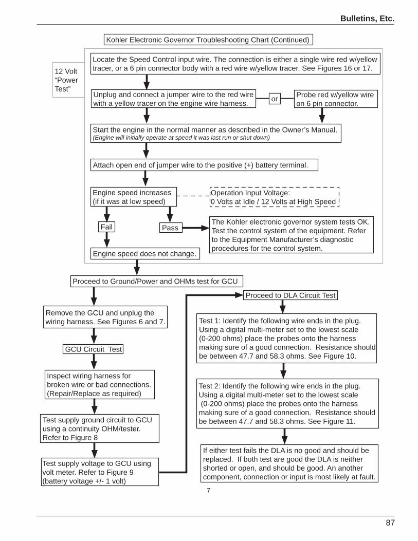
87
Bulletins, Etc.
7
Test 1: Identify the following wire ends in the plug. Using a digital multi-meter set to the lowest scale (0-200 ohms) place the probes onto the harness making sure of a good connection. Resistance should be between 47.7 and 58.3 ohms. See Figure 10.
If either test fails the DLA is no good and should be replaced. If both test are good the DLA is neither shorted or open, and should be good. An another component, connection or input is most likely at fault.
GCU Circuit Test
Remove the GCU and unplug the wiring harness. See Figures 6 and 7.
Test 2: Identify the following wire ends in the plug. Using a digital multi-meter set to the lowest scale (0-200 ohms) place the probes onto the harness making sure of a good connection. Resistance should be between 47.7 and 58.3 ohms. See Figure 11.
Test supply voltage to GCU using volt meter. Refer to Figure 9 (battery voltage +/- 1 volt)
Inspect wiring harness for broken wire or bad connections. (Repair/Replace as required)
Test supply ground circuit to GCU using a continuity OHM/tester. Refer to Figure 8
Locate the Speed Control input wire. The connection is either a single wire red w/yellow tracer, or a 6 pin connector body with a red wire w/yellow tracer. See Figures 16 or 17.
Unplug and connect a jumper wire to the red wire with a yellow tracer on the engine wire harness.
Start the engine in the normal manner as described in the Owner’s Manual.(Engine will initially operate at speed it was last run or shut down)
Attach open end of jumper wire to the positive (+) battery terminal.
Engine speed increases (if it was at low speed)
Engine speed does not change.
The Kohler electronic governor system tests OK. Test the control system of the equipment. Refer to the Equipment Manufacturer’s diagnostic procedures for the control system.
Proceed to Ground/Power and OHMs test for GCU
12 Volt “PowerTest”
Probe red w/yellow wire on 6 pin connector.or
Fail Pass
Proceed to DLA Circuit Test
Operation Input Voltage:0 Volts at Idle / 12 Volts at High Speed
Kohler Electronic Governor Troubleshooting Chart (Continued)
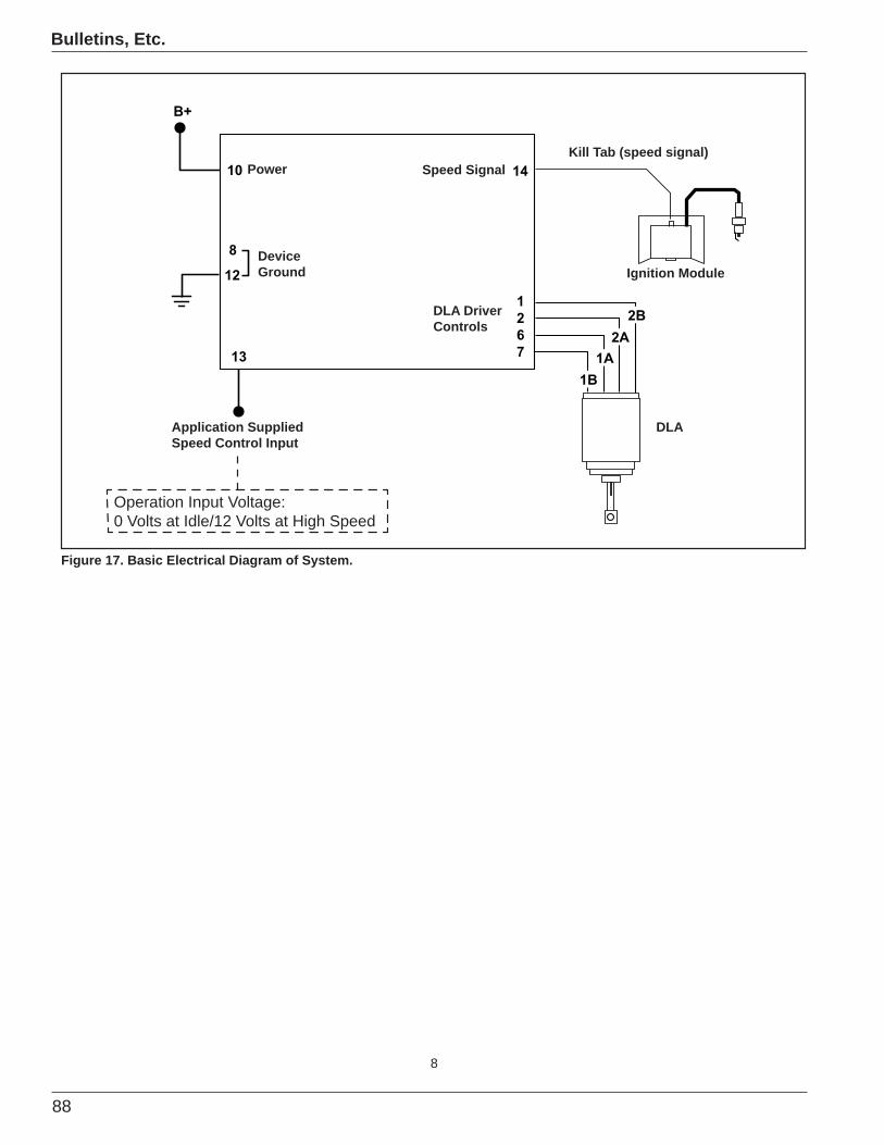
88
Bulletins, Etc.
8
B+
10
8
12
13
14
1267
1B1A
2A2B
Application Supplied Speed Control Input
Figure 17. Basic Electrical Diagram of System.
Operation Input Voltage: 0 Volts at Idle/12 Volts at High Speed
DeviceGround
Power Speed SignalKill Tab (speed signal)
DLA DriverControls
DLA
Ignition Module

89
Bulletins, Etc.
Litho In U.S.A. 7/07 ENGINE DIVISION, KOHLER CO., KOHLER, WISCONSIN 53044
Kohler Engines Truck-Mounted Applications Grounding InstructionsThere have been some reports regarding poor cranking performance on Kohler Engine-powered truck-mounted air compressors.
improperly grounded. Some installations are found to utilize the vcompressor.
The following items are suggested. NOTE:
for cranking most single cylinder engine models.
terminal to ground. Make sure that the remainder of the circuit from the negative terminal to the engine block is electrically
the chart below for SAE size and length recommendations. Always use the shortest length of wire possible without stressing the wire.
SAE Cable Size Max. Length6 Gauge 60.0 in. (152.4 cm)4 Gauge 86.0 in. (218.4 cm)2 Gauge 144.0 in. (365.7 cm)
Optional ground cable attachment points (application dependant).
Positive Battery Cable attachment (Solenoid post).t (Sole oound caable att
2007-01

90
Bulletins, Etc.
91
Technician’s Service Test
Section 9Technician’s Service Test
This section contains two tests. The Gasoline test is 40 multiple-choice questions; the Diesel test is 10 multiple-choice questions. All questions have at least four possible answers, letters a, b, c, and d. Select the ONE best answer and mark your answer sheet by placing a dark “X” over the letter that
Example:
25. The Kohler Engine plant is located in:a. Chicago, IL.b. Kohler, WI.c. Phoenix, AZ.d. none of the above.
In this example the best answer is b, so you would place an “X” over the letter on your answer sheet like shown here:
a b c d
Use a soft pencil to mark your answers. If you accidentally mark the wrong answer, erase it completely and mark the correct answer. Do not mark more than one answer for any one question. If two answers are marked, the question will be marked wrong. Any questions regarding the scoring of this test should be addressed with your Central Distributor.
the test, remove the answer sheet and return it to your Central Distributor.
A score of 75% or better will satisfy your requirement of attending the annual technicians’ service program.
If you are a dealer for gasoline only, you will not need to take the diesel test.
If you are a dealer for diesel only, you will not need to take the gasoline test.
If you are gasoline and diesel, you will need to take both tests.
Please remember that the answers to all of these questions can be found within the book. It is
X
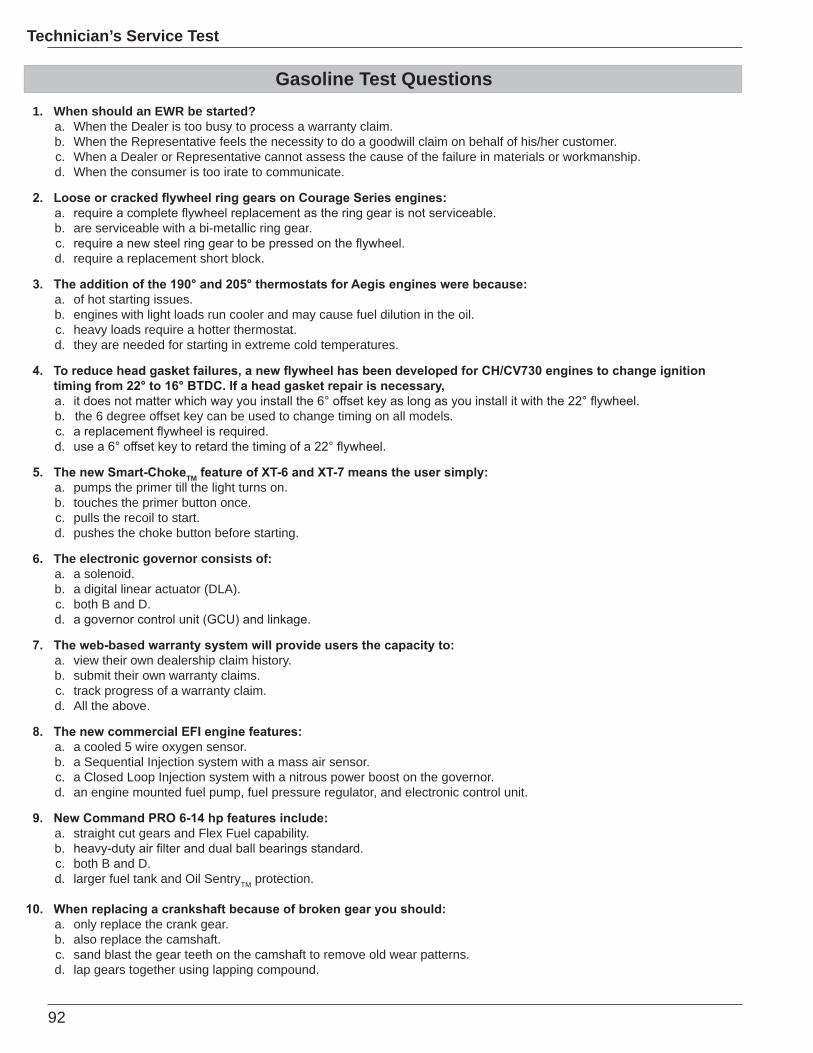
92
Technician’s Service Test
Gasoline Test Questions1. When should an EWR be started?
a. When the Dealer is too busy to process a warranty claim.b. When the Representative feels the necessity to do a goodwill claim on behalf of his/her customer.c. When a Dealer or Representative cannot assess the cause of the failure in materials or workmanship.d. When the consumer is too irate to communicate.
b. are serviceable with a bi-metallic ring gear.
d. require a replacement short block.
a. of hot starting issues.b. engines with light loads run cooler and may cause fuel dilution in the oil.c. heavy loads require a hotter thermostat.d. they are needed for starting in extreme cold temperatures.
b. the 6 degree offset key can be used to change timing on all models.
TMa. pumps the primer till the light turns on.b. touches the primer button once.c. pulls the recoil to start.d. pushes the choke button before starting.
6. The electronic governor consists of:a. a solenoid.b. a digital linear actuator (DLA).c. both B and D.
a. view their own dealership claim history.b. submit their own warranty claims.c. track progress of a warranty claim.d. All the above.
a. a cooled 5 wire oxygen sensor.b. a Sequential Injection system with a mass air sensor.c. a Closed Loop Injection system with a nitrous power boost on the governor.d. an engine mounted fuel pump, fuel pressure regulator, and electronic control unit.
a. straight cut gears and Flex Fuel capability.
c. both B and D.d. larger fuel tank and Oil SentryTM protection.
a. only replace the crank gear.b. also replace the camshaft. c. sand blast the gear teeth on the camshaft to remove old wear patterns.d. lap gears together using lapping compound.
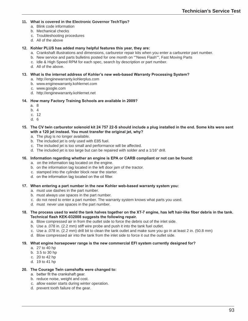
93
Technician’s Service Test
11. What is covered in the Electronic Governor TechTips?a. Blink code informationb. Mechanical checksc. Troubleshooting proceduresd. All of the above
a. Crankshaft illustrations and dimensions, carburetor repair kits when you enter a carburetor part number.b. New service and parts bulletins posted for one month on “”News Flash””, Fast Moving Partsc. Idle & High Speed RPM for each spec, search by description or part number.d. All of the above.
a. http://enginewarranty.kohlerplus.comb. www.enginewarranty.kohlernet.comc. www.google.comd. http://enginewarranty.kohlernet.net
a. 8b. 4c. 12d. 6
a. The plug is no longer available.b. The included jet is only used with E85 fuel.c. The included jet is too small and performance will be affected.d. The included jet is too large but can be repaired with solder and a 1/16” drill.
a. on the information tag located on the engine.b. on the information tag located in the left door jam of the tractor.c. stamped into the cylinder block near the starter.
a. must use dashes in the part number.b. must always use spaces in the part number.c. do not need to enter a part number. The warranty system knows what parts you used.d. must never use spaces in the part number.
a. Blow compressed air in from the outlet side to force the debris out of the inlet side.b. Use a .078 in. (2.2 mm) stiff wire probe and push it into the tank fuel outlet.c. Use a .078 in. (2.2 mm) drill bit to clean the tank outlet and make sure you go in at least 2 in. (50.8 mm) d. Blow compressed air into the tank from the inlet side to force it out the outlet side.
a. 27 to 40 hpb. 3.5 to 30 hpc. 20 to 42 hpd. 19 to 41 hp
b. reduce noise, weight and cost.c. allow easier starts during winter operation.d. prevent tooth failure of the gear.
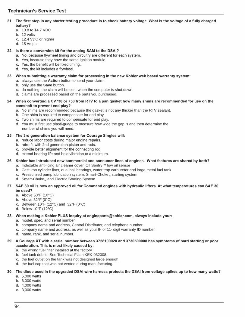
94
Technician’s Service Test
a. 13.8 to 14.7 VDCb. 12 voltsc. 12.4 VDC or higherd. 15 Amps
b. Yes, because they have the same ignition module.
a. always use the Action button to send your claim.b. only use the Save button.c. do nothing, the claim will be sent when the computer is shut down.d. claims are processed based on the parts you purchased.
a. No shims are recommended because the gasket is not any thicker than the RTV sealant.b. One shim is required to compensate for end play.c. Two shims are required to compensate for end play.
number of shims you will need.
a. reduce labor costs during major engine repairs.
c. provide better alignment for the connecting rod.d. extend bearing life and hold vibration to a minimum.
a. Indexable anti-icing air cleaner cover, Oil Sentry™ low oil sensorb. Cast iron cylinder liner, dual ball bearings, water trap carburetor and large metal fuel tankc. Pressurized pump lubrication system, Smart-Choke™ starting systemd. Smart-Choke™ and Electric Starting System
be used?a. Above 50°F (10°C)b. Above 32°F (0°C)c. Between 10°F (12°C) and 32°F (0°C) d. Below 10°F (12°C)
a. model, spec, and serial number.b. company name and address, Central Distributor, and telephone number.c. company name and address, as well as your 9- or 11- digit warranty ID number.d. name, rank, and serial number.
b. fuel tank debris. See Technical Flash KEK-032008.c. the fuel outlet on the tank was not designed large enough.d. the fuel cap that was not vented during manufacturing.
a. 5,000 wattsb. 6,000 wattsd. 4,000 wattsc. 3,000 watts
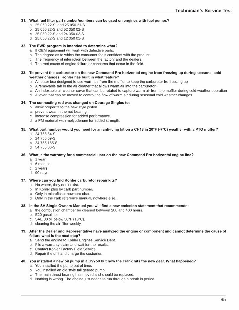
95
Technician’s Service Test
a. 25 050 22-S and 25 050 21-Sb. 25 050 22-S and 52 050 02-Sc. 25 050 22-S and 24 050 03-Sd. 25 050 22-S and 12 050 01-S
a. If OEM equipment will work with defective parts.
c. The frequency of interaction between the factory and the dealers.
b. A removable tab in the air cleaner that allows warm air into the carburetor
a. prevent wear in the rod bearing.c. increase compression for added performance.d. a PM material with molybdenum for added strength.
a. 24 755 64-Sb. 24 755 69-Sc. 24 755 165-Sd. 54 755 06-S
a. 1 yearb. 6 monthsc. 2 yearsd. 90 days
a. No where, they don’t exist.b. In Kohler plus by carb part number.
d. Only in the carb reference manual, nowhere else.
a. the combustion chamber be cleaned between 200 and 400 hours.b. E20 gasoline.c. SAE 30 oil below 50°F (10°C).
a. Send the engine to Kohler Engines Service Dept.b. File a warranty claim and wait for the results.c. Contact Kohler Factory Field Service.d. Repair the unit and charge the customer.
a. You installed the pump out of time.b. You installed an old style tall geared pump.c. The main thrust bearing has moved and should be replaced.d. Nothing is wrong. The engine just needs to run through a break in period.
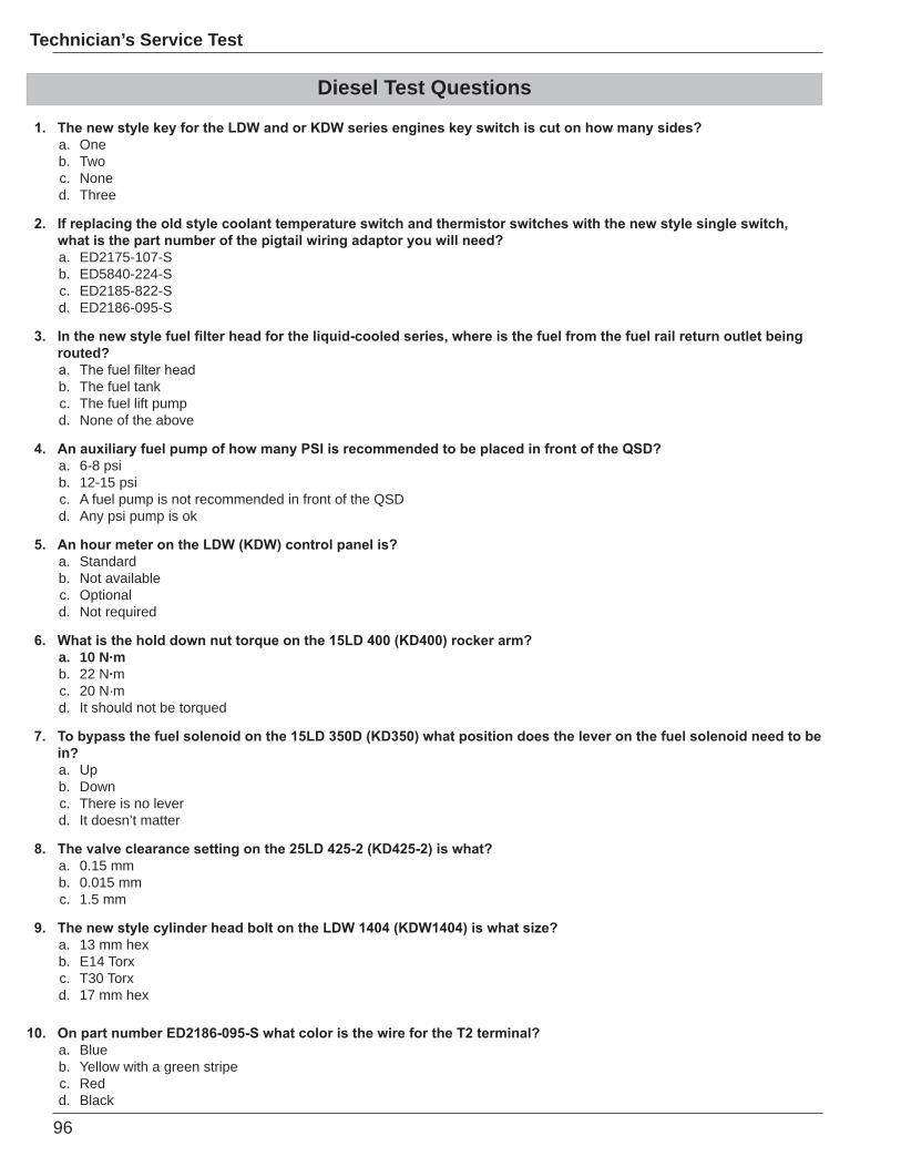
96
Technician’s Service Test
Diesel Test Questions
a. Oneb. Twoc. Noned. Three
a. ED2175-107-Sb. ED5840-224-Sc. ED2185-822-Sd. ED2186-095-S
routed?
b. The fuel tankc. The fuel lift pumpd. None of the above
a. 6-8 psib. 12-15 psic. A fuel pump is not recommended in front of the QSDd. Any psi pump is ok
a. Standardb. Not availablec. Optionald. Not required
a. 10 N·mb. 22 N·mc. 20 N·md. It should not be torqued
in?a. Upb. Downc. There is no leverd. It doesn’t matter
a. 0.15 mmb. 0.015 mmc. 1.5 mm
a. 13 mm hexb. E14 Torxc. T30 Torxd. 17 mm hex
a. Blueb. Yellow with a green stripec. Redd. Black
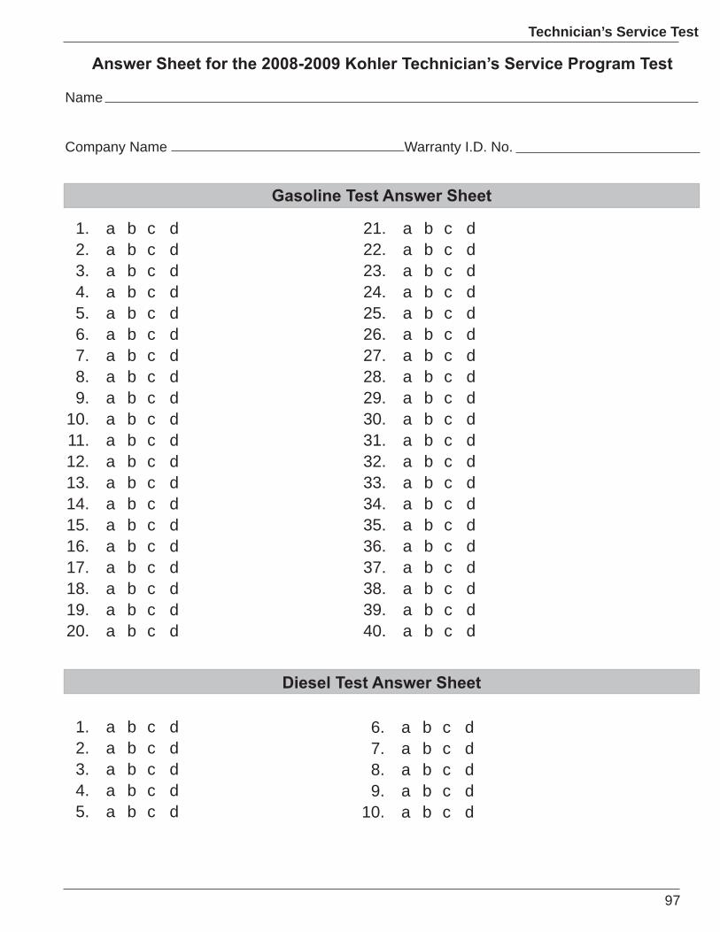
97
Technician’s Service Test
1. a b c d2. a b c d3. a b c d4. a b c d5. a b c d
1. a b c d2. a b c d3. a b c d4. a b c d5. a b c d6. a b c d7. a b c d8. a b c d9. a b c d
10. a b c d11. a b c d12. a b c d13. a b c d14. a b c d15. a b c d16. a b c d17. a b c d18. a b c d19. a b c d20. a b c d
21. a b c d22. a b c d23. a b c d24. a b c d25. a b c d26. a b c d27. a b c d28. a b c d29. a b c d30. a b c d31. a b c d32. a b c d33. a b c d34. a b c d35. a b c d36. a b c d37. a b c d38. a b c d39. a b c d40. a b c d
6. a b c d7. a b c d8. a b c d9. a b c d
10. a b c d
Name
Company Name Warranty I.D. No.

98
Technician’s Service Test


ENGINE DIVISION, KOHLER CO., KOHLER, WISCONSIN 53044 LITHO IN U.S.A.