Embed Size (px)
Citation preview
UNBRICK YOUR ROUTER … (e.g. NETGEAR R6400 v2)
Most mistakes happen when you rush into things or when you do not read the instructions. The first necessity (especially if you are a novice) is to read and understand. Next, ensure that you have the right tools necessary. Only after that attempt to touch the router!! The first thing we do will be to understand this device called router – primarily with respect to how it boots up, what role the firmware has and how and when the firmware can be force loaded into the router. I will attempt to limit technical jargon here.
TABLE OF CONTENTS This guide is paced as follows… • Section I … A brief idea of how a router boots up
• Section II … Trying to de-brick the R6400 without using a serial cable (TFTP & NMRPFLASH)
• Section III … A: Tools required for serial cable debrick B: Inside the router C: De-Bricking using the serial cable
Bricked router?? No problem. Let’s enjoy unbricking it. There is no fear as long as we understand what we are doing. After all, this is just a Router and not a Rocket!!
DISCLAIMER: This guide is for those who are confident enough to use it at their own risk. No guarantee of any kind is provided or implied – and no support offered. This is specifically for the Netgear R6400v2 with board U12H332T20 (or 30). It can be tweaked to work for other boards and other routers
Neither the author nor this forum is liable to take any damages or culpability for anything that you do with this guide. There is no sale or financial transaction involved here.
Please feel free to read this and use the instructions as you deem fit
Please feel free to close this and delete if you do not agree to this disclaimer
Version 1.33
One of the prime causes of bricking your router is making a mistake while trying to revert back to OEM firmware. Know that there is a process to do this … simple selection of the stock firmware from dd-wrt Administration tab may not work. In his guide to install dd-wrt to
Netgear R6400v2, member egc has
listed the procedure and also attached
the files necessary to revert back to
stock firmware. You may not need this
guide if you adhere to that.
First know how to avoid bricking your router.
SECTION I: UNDERSTANDING THE BASICS
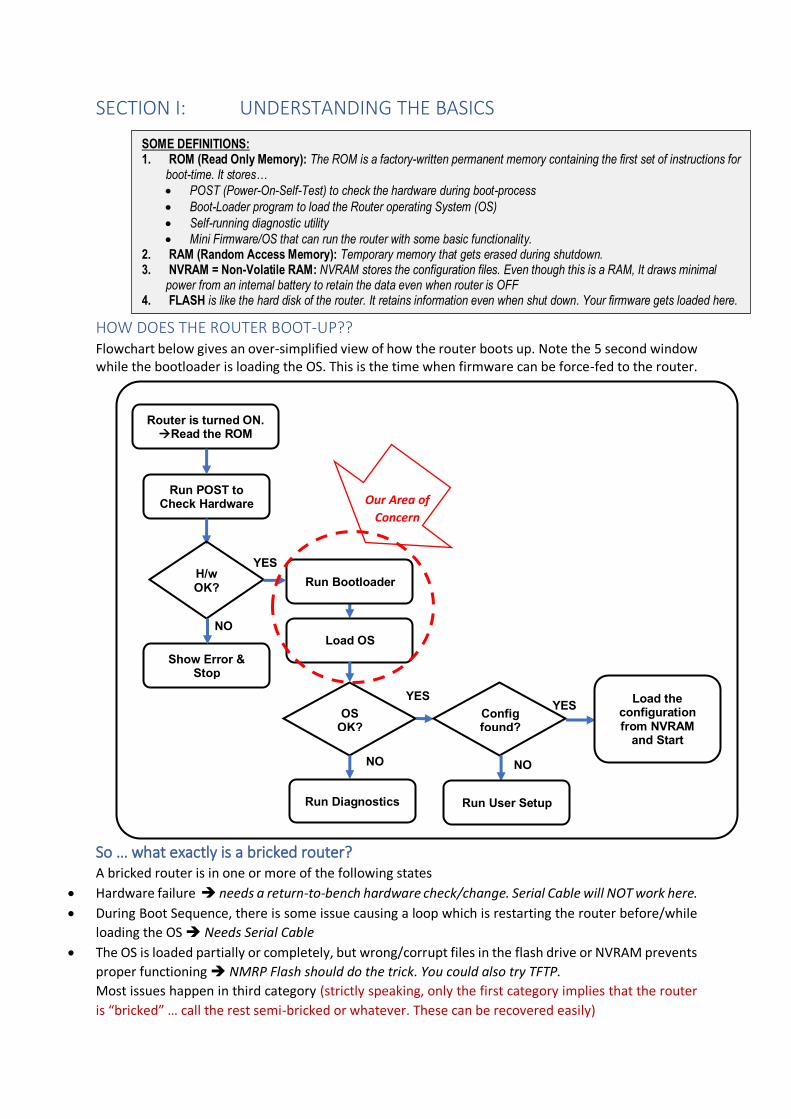
HOW DOES THE ROUTER BOOT-UP?? Flowchart below gives an over-simplified view of how the router boots up. Note the 5 second window while the bootloader is loading the OS. This is the time when firmware can be force-fed to the router.
So … what exactly is a bricked router? A bricked router is in one or more of the following states
• Hardware failure ➔ needs a return-to-bench hardware check/change. Serial Cable will NOT work here.
• During Boot Sequence, there is some issue causing a loop which is restarting the router before/while
loading the OS ➔ Needs Serial Cable
• The OS is loaded partially or completely, but wrong/corrupt files in the flash drive or NVRAM prevents
proper functioning ➔ NMRP Flash should do the trick. You could also try TFTP.
Most issues happen in third category (strictly speaking, only the first category implies that the router
is “bricked” … call the rest semi-bricked or whatever. These can be recovered easily)
SOME DEFINITIONS: 1. ROM (Read Only Memory): The ROM is a factory-written permanent memory containing the first set of instructions for
boot-time. It stores…
• POST (Power-On-Self-Test) to check the hardware during boot-process
• Boot-Loader program to load the Router operating System (OS)
• Self-running diagnostic utility
• Mini Firmware/OS that can run the router with some basic functionality. 2. RAM (Random Access Memory): Temporary memory that gets erased during shutdown. 3. NVRAM = Non-Volatile RAM: NVRAM stores the configuration files. Even though this is a RAM, It draws minimal
power from an internal battery to retain the data even when router is OFF 4. FLASH is like the hard disk of the router. It retains information even when shut down. Your firmware gets loaded here.
Router is turned ON. →Read the ROM
Run POST to Check Hardware
Show Error & Stop
Run Bootloader H/w OK?
NO
YES
Load OS
OS OK?
NO
YES
Run Diagnostics
Config found?
NO
YES
Run User Setup
Load the configuration from NVRAM
and Start
Our Area of
Concern

ROUTER RESET: Before trying anything else, let’s try to reset the router. This may resolve the
problem.
How to reset the R6400v2: The textbook method press the reset button for 7-10 seconds till the power LED starts to
blink. Release the pin. Router will reboot in a few seconds.
However, I had my router bricked and blinking once per second. The above method did not
work. So I tried the other method (as below)
• Switch off the router and disconnect all cables. Wait 10 seconds.
• Press a pin into the reset slot and connect the power cable (press the ON switch if
router is off)
• The LEDS wil blink in multi-colour and display a dancing lights show of sorts … after
that only power LED will glow … and then the lights dance for the second time. While
the lights are still dancing, release the reset pin. The power LED will glow steady orange
once again.
▪ If you are just resetting. Wait for router to start and give it a full 5 minutes to
stabilize before you try any changes
▪ If you plan to force some firmware into the router via TFTP or NMRPFLASH,
the time to start the operation is while the Power LED is steady and other LEDs
(except LAN) are off.
HAS THIS RESOLVED YOUR ISSUE??
YES ➔ Ignore the rest of this guide
NO ➔ Let’s find out what type of bricked status this router is in…
This is very simple to do.
a) Set the LAN’s IP address to 192.168.1.2 [Show me how to do it]
b) Ping the router which should be at 192.168.1.1 [Show me how to ping]
Successful ping implies the Router’s OS is getting partially or fully loaded. (OS allocates the
IP address to the router). We should be able to revive without a serial cable.
We will first try to use NMRPFLASH to revive the router. If this fails, we will try the serial cable
option.
Some may want to try out using tftp before going on to the NMRPFlash. This is explained below –
but you may skip this as NMRPFLASH is a more sure-shot way of doing this for Netgear Routers.
OPTIONAL ATTEMPT (using windows tftp client to revive the router) 1. Enable Windows TFTP Client (which is usually disabled by default) [Show me how]
2. Change Laptop’s LAN IP to same network as the router [Show me how]
3. Open command Prompt and browse to the directory/folder where the firmware is stored
4. Type tftp -i 192.168.1.1 PUT firmware.chk [DO NOT PRESS ENTER]
5. Reset the router (but without disconnecting the LAN cable) [show me how]
6. While the Router is booting (as soon as power LED glows) – execute the tftp command that
we had typed and kept ready in the command window
TFTP seldom works with semi-bricked Netgear Routers. I have never succeeded at this. It seems
this is because Netgear Routers look for an initial file called vmlinuz, and rejects all others.
To know more on this, please visit https://forum.dd-wrt.com/phpBB2/viewtopic.php?p=1049230
Section II: Using NMRPFLASH Use the NMRP Flash to revert to stock – or to load dd-wrt first flash file (factory-to-ddwrt.chk).
You could use this as a tool to revert back to Kong’s build from a BS build.
This utility is relatively safe as there are no reports of this bricking the router – but it is strongly
advised to read, understand and perform … of course at your own risk
Resources • Download the NMRPFLASH file from https://github.com/jclehner/nmrpflash/releases
You can read more about NMRPFLASH at https://github.com/jclehner/nmrpflash.
• Download & Install WinPCap from https://www.winpcap.org/install/default.htm
• Download the firmware that you want to load. This could be stock firmware from netgear
website – or the correct dd-wrt first flash version from dd-wrt website. OEM firmware for
the R6400v2 is found at https://www.netgear.com/support/product/R6400v2.aspx#download
Preparing to do the flashing 1. Copy <firmware.chk> & the <nmrpflash.exe> files to same directory/folder (Say D:\NETGEAR)
2. Connect a LAN cable from your laptop/PC to one of the LAN ports on the router
3. Change Laptop’s LAN IP to same network as the router [explained here]
4. Reset your router [explained here]
Flashing the Router Step 1: Find out the name of the ethernet connection
• Open Command Prompt in administrator mode. Navigate to same folder as nmrpflash.exe.
• Type nmrpflash -L
This will show you the various connections available. The output will be something like net0 192.168.1.2 xx:xx:xx:xx:xx:xx
In this setup, the LAN (192.168.1.2) is named net0.
xx:xx:xx:xx:xx:xx is the MAC address of the LAN card.
There will be other entries (such as your WiFi) under different connection names
Step 2: Ready the command prompt • Type nmrpflash -i net0 -f <Firmware.chk> [DO NOT PRESS ENTER]
(net0 is the name of the LAN and Firmware.chk is the name of the firmware)
Syntax for use of nmrpflash is : nmrplash -i <LAN connection Name> -f <Firmware with path>
Step 3: Perform the task • Switch the router off. Wait 10 seconds and then switch it on again. While the lights are
still dancing, execute the NMRPFLASH command that you typed and kept ready in step 3.
You should now be seeing a message like
“Advertising NMRP server on eth0 … / ”
▪ The first run of NMRP, will give an error “Timeout while waiting for TFTP_UL_REQ”, →
immediately run nmrp again (do this quickly press UP arrow key and then press enter)
▪ If your transfer started successfully you will see a message confirming that the firmware
is getting uploaded. Now the most important thing is patience … you may need to wait for
even 10-15 minutes for the file to get correctly transferred. (If you are the impatient type,
use the -v option with the NMRPFLASH command. This will constantly give a verbose
output showing that something is getting transferred.)
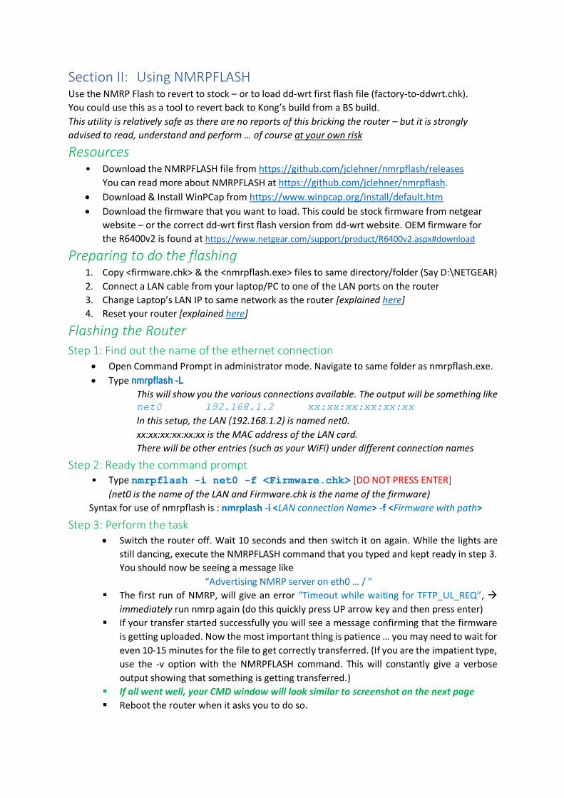
▪ If all went well, your CMD window will look similar to screenshot on the next page
▪ Reboot the router when it asks you to do so.
Didn’t work? … here are the most common reasons for this ▪ The timing is important… you need to start when the router’s power LED light has just
started a steady glow. It is better to keep nmrp broadcasting before this time (i.e. start
nmrp when the router lights are still dancing).
▪ NMRPFLASH was started too late (It needs to start when the ping returns TTL=100. If you
started this when the value TTL=64, you will most probably fail. You may want to have a
second cmd window constantly pinging the router).
▪ Windows Defender or your antivirus may be blocking nmrpflash.
See the screenshot below. If all went well, your router should be displaying similar scenario and your
router must be working
SECTION III (A): TOOLS FOR SERIAL CABLE SUPPORT
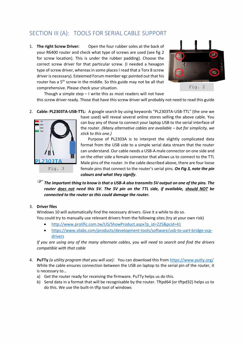
1. The right Screw Driver: Open the four rubber soles at the back of
your R6400 router and check what type of screws are used (see fig 2
for screw location). This is under the rubber padding). Choose the
correct screw driver for that particular screw. (I needed a hexagon
type of screw driver, whereas in some places I read that a Torx 8 screw
driver is necessary). Esteemed Forum member egc pointed out that his
router has a 5th screw in the middle. So this guide may not be all that
comprehensive. Please check your situation.
Though a simple step – I write this as most readers will not have
this screw driver ready. Those that have this screw driver will probably not need to read this guide
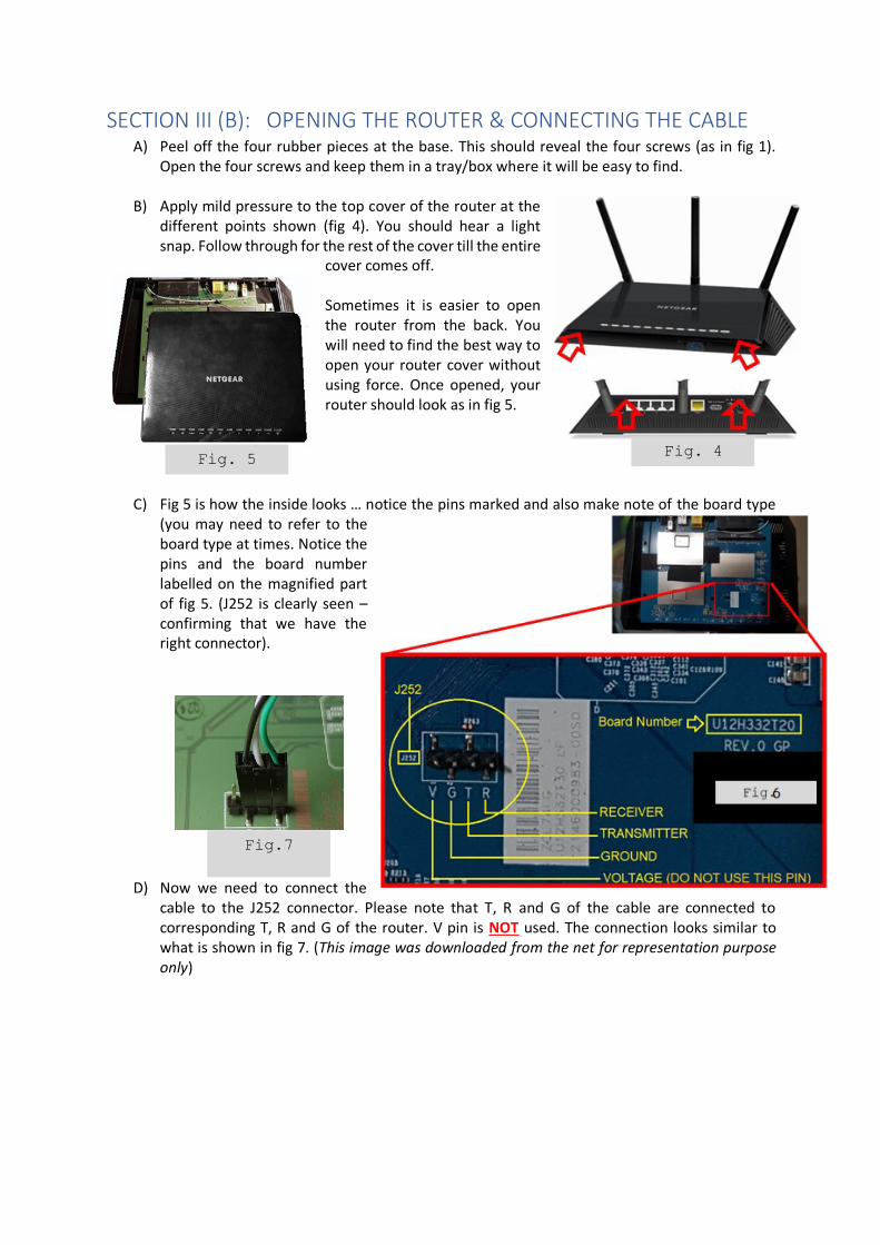
2. Cable: PL2303TA-USB-TTL: A google search by using keywords “PL2303TA-USB-TTL” (the one we have used) will reveal several online stores selling the above cable. You can buy any of those to connect your laptop USB to the serial interface of the router. (Many alternative cables are available – but for simplicity, we stick to this one.)
Purpose of PL2303A is to interpret the slightly complicated data
format from the USB side to a simple serial data stream that the router
can understand. Our cable needs a USB-A male connector on one side and
on the other side a female connector that allows us to connect to the TTL
Male pins of the router. In the cable described above, there are four loose
female pins that connect to the router’s serial pins. On Fig 3, note the pin
colours and what they signify.
The important thing to know is that a USB-A also transmits 5V output on one of the pins. The
router does not need this 5V. The 5V pin on the TTL side, if available, should NOT be
connected to the router as this could damage the router.
3. Driver files Windows 10 will automatically find the necessary drivers. Give it a while to do so.
You could try to manually use relevant drivers from the following sites (try at your own risk)
• http://www.prolific.com.tw/US/ShowProduct.aspx?p_id=225&pcid=41
• https://www.silabs.com/products/development-tools/software/usb-to-uart-bridge-vcp-
drivers
If you are using any of the many alternate cables, you will need to search and find the drivers
compatible with that cable
4. PuTTy (a utility program that you will use): You can download this from https://www.putty.org/ While the cable ensures connection between the USB on laptop to the serial pin of the router, it is necessary to… a) Get the router ready for receiving the firmware. PuTTy helps us do this. b) Send data in a format that will be recognisable by the router. Tftpd64 (or tftpd32) helps us to
do this. We use the built-in tftp tool of windows
Fig. 3
Fig. 2
SECTION III (B): OPENING THE ROUTER & CONNECTING THE CABLE A) Peel off the four rubber pieces at the base. This should reveal the four screws (as in fig 1).
Open the four screws and keep them in a tray/box where it will be easy to find.
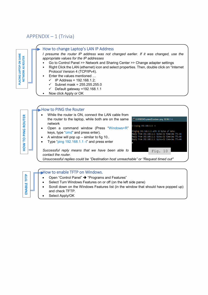
B) Apply mild pressure to the top cover of the router at the different points shown (fig 4). You should hear a light snap. Follow through for the rest of the cover till the entire
cover comes off. Sometimes it is easier to open the router from the back. You will need to find the best way to open your router cover without using force. Once opened, your router should look as in fig 5.
C) Fig 5 is how the inside looks … notice the pins marked and also make note of the board type (you may need to refer to the board type at times. Notice the pins and the board number labelled on the magnified part of fig 5. (J252 is clearly seen – confirming that we have the right connector).
D) Now we need to connect the cable to the J252 connector. Please note that T, R and G of the cable are connected to corresponding T, R and G of the router. V pin is NOT used. The connection looks similar to what is shown in fig 7. (This image was downloaded from the net for representation purpose only)
Fig.7
Fig. 4 Fig. 5

E) We need to verify if the interface is correctly connected correctly … Windows-10 laads the driver automatically. For the rest, the driver will need to be installed.
(Unzip. Find the .inf file and right-click and choose install)
On your laptop, open Control Panel ➔
Device Manager. Then click on View Menu and
choose “Devices by Type”. Now, scroll down to
look at the entry “Ports (COM & LPT)”.
Under this entry (like in fig 8), you
should see “Prolific USB-to-Serial Comm Port
(COM5) or something like that. This is the
connection we just made. Note that this is in
COM5.
This confirms connection is correctly made!
SECTION III (C): DE-BRICKING USING THE SERIAL CABLE INTERFACE One of the purposes of the serial cable is to “hold” the OS Loading period and give us more
time to load the firmware. Older routers used to allow only 1 second, and things were much
more difficult, requiring more of the serial cable route to resolve.
A) Install PuTTy. Right click icon and open in administrator mode. Click on the entry names
“Serial” at the bottom of the left pane (as in fig 9)
B) Check conditions before starting the process
• Router needs to be OFF and ready to be powered ON
• Serial cable is connected (we will use PuTTy to
communicate with the router via this interface)
C) Power ON the router. Press the “Open” button and a
console window will open up. This window will display
information received from the serial interface of the
router as it boots up
D) Keep pressing Ctrl+C till the signals stop at a CFE>
command prompt. The router Power LED should be a
steady glow now
Most texts suggest doing a TFTP after this (explained HERE),
but my suggestion is to use the NMRPFLASH utility
(explained HERE) because this tool uses Netgear’s NMRP protocol to transfer the factory
image. Since this router is netgear, NMRPFLASH should be the easier and safer choice.
You will find other third-party tools like TFTPD32 or TFTPD64 which allows running the TFTP
process through graphic interfaces.
Your router should be unbricked now. If not … you can try the serial cable thing once again. You could
try one of the other serial cable methods or you may need to take this to the OEM test-bench for
hardware repairs.
Fig.8
Fig 9
APPENDIX – 1 (Trivia)
How to change Laptop’s LAN IP Address I presume the router IP address was not changed earlier. If it was changed, use the
appropriate values for the IP addresses
• Go to Control Panel >> Network and Sharing Center >> Change adapter settings
• Right Click the LAN (ethernet) icon and select properties. Then, double click on “Internet
Protocol Version 4 (TCP/IPv4).
• Enter the values mentioned …
✓ IP Address = 192.168.1.2;
✓ Subnet mask = 255.255.255.0
✓ Default gateway =192.168.1.1
• Now click Apply or OK
How to PING the Router • While the router is ON, connect the LAN cable from
the router to the laptop, while both are on the same
network
• Open a command window (Press “Windows+R”
keys, type “cmd” and press enter).
• A window will pop up – similar to fig 10..
• Type “ping 192.168.1.1 -t” and press enter
Successful reply means that we have been able to
contact the router.
Unsuccessful replies could be “Destination host unreachable” or “Request timed out"
How to enable TFTP on Windows. • Open “Control Panel” ➔ “Programs and Features”
• Select Turn Windows Features on or off (on the left side pane)
• Scroll down on the Windows Features list (in the window that should have popped up)
and check TFTP.
• Select Apply/OK
Fig. 10


![Captive Considerations What to know, What to avoid #[insert hashtag here]](https://img.pdfslide.us/doc/110x75/56649e2f5503460f94b1f468/captive-considerations-what-to-know-what-to-avoid-insert-hashtag-here.jpg)