Embed Size (px)
Citation preview
Table of Contents
ENGINE MANAGEMENT SYSTEMS
Subject Page
SIEMENS MS 42.0 ENGINE CONTROL SYSTEM. . . . . . . . . . . . . . . . . . . . . . 3
Overview/On Board Diagnostics . . . . . . . . . . . . . . . . . . . . . . . . . . . . . . . . . . . 4Emission Compliance . . . . . . . . . . . . . . . . . . . . . . . . . . . . . . . . . . . . . . . .6Driving Cycle . . . . . . . . . . . . . . . . . . . . . . . . . . . . . . . . . . . . . . . . . . . . . 7Federal Test Procedure (FTP) . . . . . . . . . . . . . . . . . . . . . . . . . . . . . . . . . . 8“Check Engine” (MIL) Light . . . . . . . . . . . . . . . . . . . . . . . . . . . . . . . . . . .10Diagnostic Trouble Codes (DTC) . . . . . . . . . . . . . . . . . . . . . . . . . . . . . . 1220 Pin Diagnostic Socket Deletion. . . . . . . . . . . . . . . . . . . . . . . . . . . . . . 14BMW Fault Codes . . . . . . . . . . . . . . . . . . . . . . . . . . . . . . . . . . . . . . . . . 16
Engine Management . . . . . . . . . . . . . . . . . . . . . . . . . . . . . . . . . . . . . . . . . . 17I-P-O . . . . . . . . . . . . . . . . . . . . . . . . . . . . . . . . . . . . . . . . . . . . . . . . . . .18
Scope of Input FunctionsBOSCH Oxygen Sensor. . . . . . . . . . . . . . . . . . . . . . . . . . . . . . . . . . . . . 19Camshaft Sensor . . . . . . . . . . . . . . . . . . . . . . . . . . . . . . . . . . . . . . . . . .21Crankshaft Sensor . . . . . . . . . . . . . . . . . . . . . . . . . . . . . . . . . . . . . . . . .22Misfire Detection . . . . . . . . . . . . . . . . . . . . . . . . . . . . . . . . . . . . . . . . . .23Mass Air Flow (HFM) . . . . . . . . . . . . . . . . . . . . . . . . . . . . . . . . . . . . . . . 26
Scope of Output FunctionsVANOS control . . . . . . . . . . . . . . . . . . . . . . . . . . . . . . . . . . . . . . . . . . . 27Electric Fan . . . . . . . . . . . . . . . . . . . . . . . . . . . . . . . . . . . . . . . . . . . . . . 31Running Losses. . . . . . . . . . . . . . . . . . . . . . . . . . . . . . . . . . . . . . . . . . . 32Secondary Air Injection . . . . . . . . . . . . . . . . . . . . . . . . . . . . . . . . . . . . . .33Fuel Injection Valves. . . . . . . . . . . . . . . . . . . . . . . . . . . . . . . . . . . . . . . .35Engine/Vehicle Speed Limitation . . . . . . . . . . . . . . . . . . . . . . . . . . . . . . .35RZV Ignition System . . . . . . . . . . . . . . . . . . . . . . . . . . . . . . . . . . . . . . . .36Resonance/Turbulence Intake System. . . . . . . . . . . . . . . . . . . . . . . . . . . 37Idle Speed Control . . . . . . . . . . . . . . . . . . . . . . . . . . . . . . . . . . . . . . . . .41Cruise Control . . . . . . . . . . . . . . . . . . . . . . . . . . . . . . . . . . . . . . . . . . . . 42Intake Jet Pump . . . . . . . . . . . . . . . . . . . . . . . . . . . . . . . . . . . . . . . . . . 43Purge Valve . . . . . . . . . . . . . . . . . . . . . . . . . . . . . . . . . . . . . . . . . . . . . . 44Torque Interfaces . . . . . . . . . . . . . . . . . . . . . . . . . . . . . . . . . . . . . . . . . . 45

Leakage Diagnosis Pump (LDP) . . . . . . . . . . . . . . . . . . . . . . . . . . . . . . . . . 46 Motor Driven Throttle Valve . . . . . . . . . . . . . . . . . . . . . . . . . . . . . . . . . . . . 51Intake Air Flow Control. . . . . . . . . . . . . . . . . . . . . . . . . . . . . . . . . . . . . . . . 55
SIEMENS MS 43.0 ENGINE CONTROL SYSTEM. . . . . . . . . . . . . . . . . . . . . .57
Introduction. . . . . . . . . . . . . . . . . . . . . . . . . . . . . . . . . . . . . . . . . . . . . . . . 58
I.P.O. . . . . . . . . . . . . . . . . . . . . . . . . . . . . . . . . . . . . . . . . . . . . . . . . . . . . .59
MS 43.0 New FunctionsElectronic Throttle Control (EML). . . . . . . . . . . . . . . . . . . . . . . . . . . . . . .60Accelerator Pedal Sensor (PWG). . . . . . . . . . . . . . . . . . . . . . . . . . . . . . . 61Electronic Throttle Valve (EDK). . . . . . . . . . . . . . . . . . . . . . . . . . . . . . . . 63Main Relay Monitor. . . . . . . . . . . . . . . . . . . . . . . . . . . . . . . . . . . . . . . . .65Engine Optimized ignition Key Off. . . . . . . . . . . . . . . . . . . . . . . . . . . . . . 66Diagnosis Module Tank Leakage (DM-TL). . . . . . . . . . . . . . . . . . . . . . . . 67DM-TL Function. . . . . . . . . . . . . . . . . . . . . . . . . . . . . . . . . . . . . . . . . . .69DM-TL Test Procedure. . . . . . . . . . . . . . . . . . . . . . . . . . . . . . . . . . . . . .70
Review Questions. . . . . . . . . . . . . . . . . . . . . . . . . . . . . . . . . . . . . . . . . . . . .74
Subject Page

SIEMENS MS 42.0 ENGINE CONTROL SYSTEM
Model: E46 equipped with M52TU Engine
Production Dates: M52TU B28: 6/98 to 6/00, M52TU B25: 6/98 to 9/00
Objectives
After completing this module you should be able to:
• Describe the engine management system monitoring required by OBD II regulation.
• Explain what is required in-order for the ECM to illuminate the MIL.
• Understand how the ECM monitors for misfires.
• Explain the relationship between the MDK and idle control valve.
• Describe the operation of the resonance charging manifold.
• List the procedure the ECM uses to carry out the tank leakage test.
• Recognize the fail-safe running characteristics of the MDK safety concept.

OBD II FUNCTION: Overview (On Board Diagnosis)
Since the 1996 model year all vehicles must meet OBD II requirements. OBD II requires themonitoring of virtually every component that can affect the emission performance of a vehi-cle plus store the associated fault code and condition in memory. If a problem is detected,the OBD II system must also illuminated a warning lamp (Malfunction Indicator Light - MIL/“Check Engine Light”” located on the vehicle instrument panel to alert the driver that a mal-function has occurred. In order to accomplish this task, BMW utilizes the Engine ControlModule (ECM/DME) as well as the Automatic Transmission Control Module (EGS/AGS) andthe Electronic Throttle Control Module (EML) to monitor and store faults associated with allcomponents/systems that can influence exhaust and evaporative emissions.
4Engine Management Systems
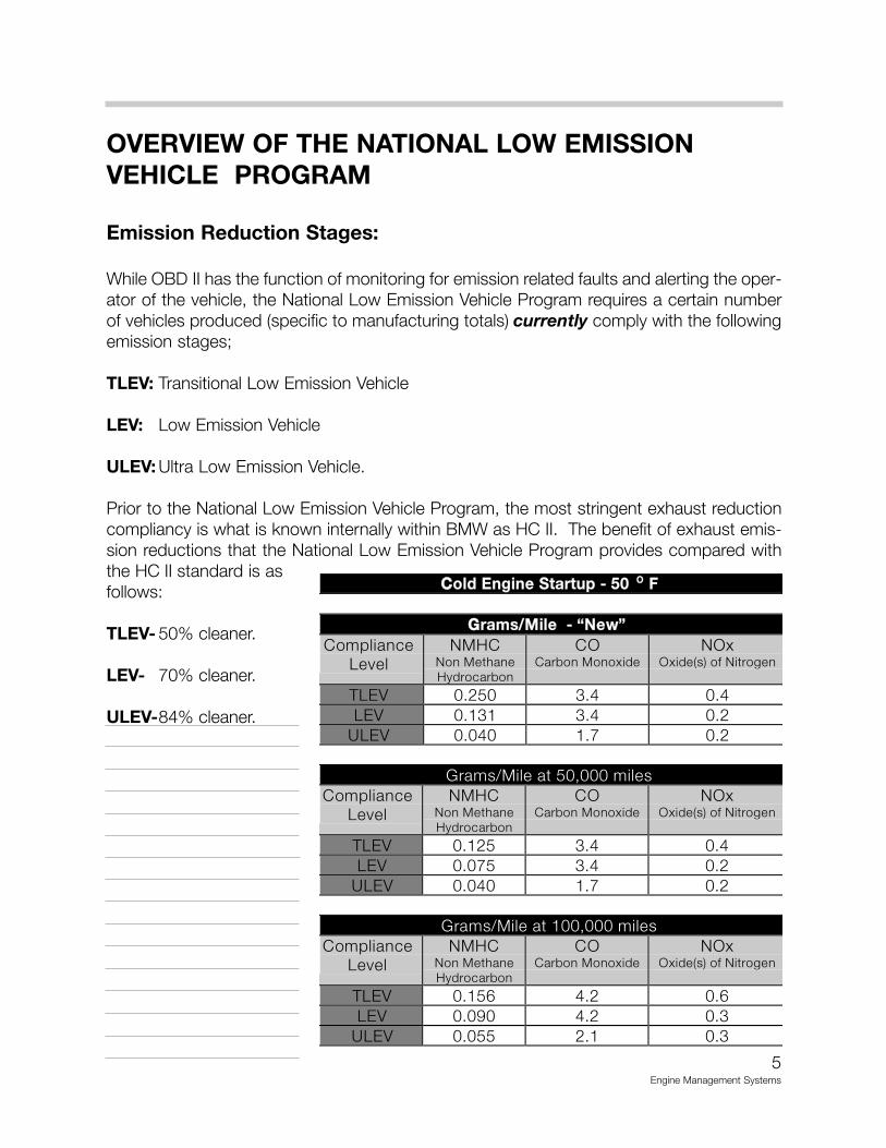
OVERVIEW OF THE NATIONAL LOW EMISSION VEHICLE PROGRAM
Emission Reduction Stages:
While OBD II has the function of monitoring for emission related faults and alerting the oper-ator of the vehicle, the National Low Emission Vehicle Program requires a certain numberof vehicles produced (specific to manufacturing totals) currently comply with the followingemission stages;
TLEV: Transitional Low Emission Vehicle
LEV: Low Emission Vehicle
ULEV: Ultra Low Emission Vehicle.
Prior to the National Low Emission Vehicle Program, the most stringent exhaust reductioncompliancy is what is known internally within BMW as HC II. The benefit of exhaust emis-sion reductions that the National Low Emission Vehicle Program provides compared withthe HC II standard is as follows:
TLEV- 50% cleaner.
LEV- 70% cleaner.
ULEV-84% cleaner.
5Engine Management Systems
������������� ��������� ����
��� ���������������������
��� ���
������������������
����������������
������������� ������
��� !"#$! %"& !"&�� !"'%' %"& !"#(�� !"!&! '") !"#
*����+�������$!,!!!�������������
��� ���
������������������
����������������
������������� ������
����� !"'#$ %"& !"&���� !"!)$ %"& !"#��(�� !"!&! '") !"#
*����+�������'!!,!!!�������������
��� ���
������������������
����������������
������������� ������
����� !"'$- &"# !"-���� !"!.! &"# !"%��(�� !"!$$ #"' !"%

6Engine Management Systems
�����
�����
�����
�����
�������
�� �!!��"#$�%#&!"����!��!������$'!#���
())� ())* ())+ ()),
�--��.* /��!! &'�" è
�&#%&�(�)* �$�(�)+�--�0. /��!! &'�" è
�&#%&�(��)* �$�(�)+��1��.* &'�" è
�&#%&�(��)���1�
�-*
'�" è�&#%&�*�),
��1�
�.)
&'�" '�" è�&#%&�.�)* �$�)�),
��1�
0.
&'�" '�" è�&#%&�(�)+ �$�)�),
�*1�
�.,�.)
/��!! '�" è�&#%&�(�)* �$�*�),
�+.�
�.,
/��!! '�" è�&#%&�(�)� �$�)�),
�� �!!��"#$�%#&!"����!��!������$'!#���
())� ())* ())+ ()),
�--��.*
$2%����'�3���!&�%!��
$2%����'�3����!&�%!����#''�'�#4� �&��&!���5(��6�.�1�"#'"� è
�&#%&�(�)* �$�(�)+�--�0.
$2%����'�3���!&�%!�� è è.�1�"#'"�
$2%����'�3����!&�%!����#''�'�#4� �&��&!���5(��6�.�1�"#'"� è
�&#%&�(��)* �$�(�)+��1��.*
$2%����'�3����!&�%!����#''�'�#4� �&��&!���5(��6�.�1�"#'"� è
�&#%&�(��)���1��-*
' $��7����%"%�.�1 è
�&#%&�*�),��1��.)
$2%����'�3����!&�%!���.�1�"#'"�
' $�$2�$�(��'�#4��%"%�.�1
"#'"�
' $��7����%"%�.�1 è
�&#%&�.�)* �$�)�)+ �$�)�),��1�0.
$2%����'�3����!&�%!�����#''�'�#4� �&��&!���5(��6�.�1
"#'"�
' $��7����%"%�.�1 è
�&#%&�(�)+ �$�)�),�*1��.,�.)
$2%����'�3����!&�%!��.�1�"#'"�
' $�$2�$�(���'�#4�%"%�.�1�"#'"�
' $��7����%"%�.�1 è
�&#%&�(�)* �$���)+ �$�*�),�+.��.,
$2%����'�3����!&�%!���.�1�"#'"�
' $�$2�$�(���'�#4��%"%.�1�"#'"�
' $��7����%"%�.�1 è
7Engine Management Systems
OBD II FUNCTION: DRIVING CYCLE
As defined within CARB mail-out 1968.1:
"Driving cycle" consists of engine startup and engine shutoff.
"Trip" is defined as vehicle operation (following an engine-off period) of duration and dri-ving style so that all components and systems are monitored at least once by the diagnosticsystem except catalyst efficiency or evaporative system monitoring. This definition is sub-ject to the limitations that the manufacturer-defined trip monitoring conditions are all moni-tored at least once during the first engine start portion of the Federal Test Procedure (FTP).
Within this text the term "customer driving cycle" will be used and is defined as enginestart-up, operation of vehicle (dependent upon customer drive style) and engine shut-off.
FEDERAL TEST PROCEDURE (FTP)
The Federal Test Procedure (FTP) is a specific driving cycle that is utilized by the EPA totest light duty vehicles and light duty truck emissions. As part of the procedure for a vehi-cle manufacturer to obtain emission certification for a particular model/engine family themanufacturer must demonstrate that the vehicle(s) can pass the FTP defined driving cycletwo consecutive times while monitoring various components/systems. Some of thecomponents/systems must be monitored either once per driving cycle or continuously.
1. Components/systems required to be monitored once within one driving cycle:
• Oxygen Sensors
• Secondary Air Injection System
• Catalyst Efficiency
• Evaporative Vapor Recovery System
NOTE: Due to the complexity involved in meeting the test criteria within the FTP defineddriving cycle, all tests may not be completed within one "customer driving cycle". Thetest can be successfully completed within the FTP defined criteria, however customerdriving styles may differ and therefore may not always monitor all involved compo-nents/systems in one "trip".
Components/systems required to be monitored continuously:
• Misfire Detection
• Fuel system
• Oxygen Sensors
• All emissions related components/systems providing or getting electrical connections to the DME, EGS, or EML.
8Engine Management Systems
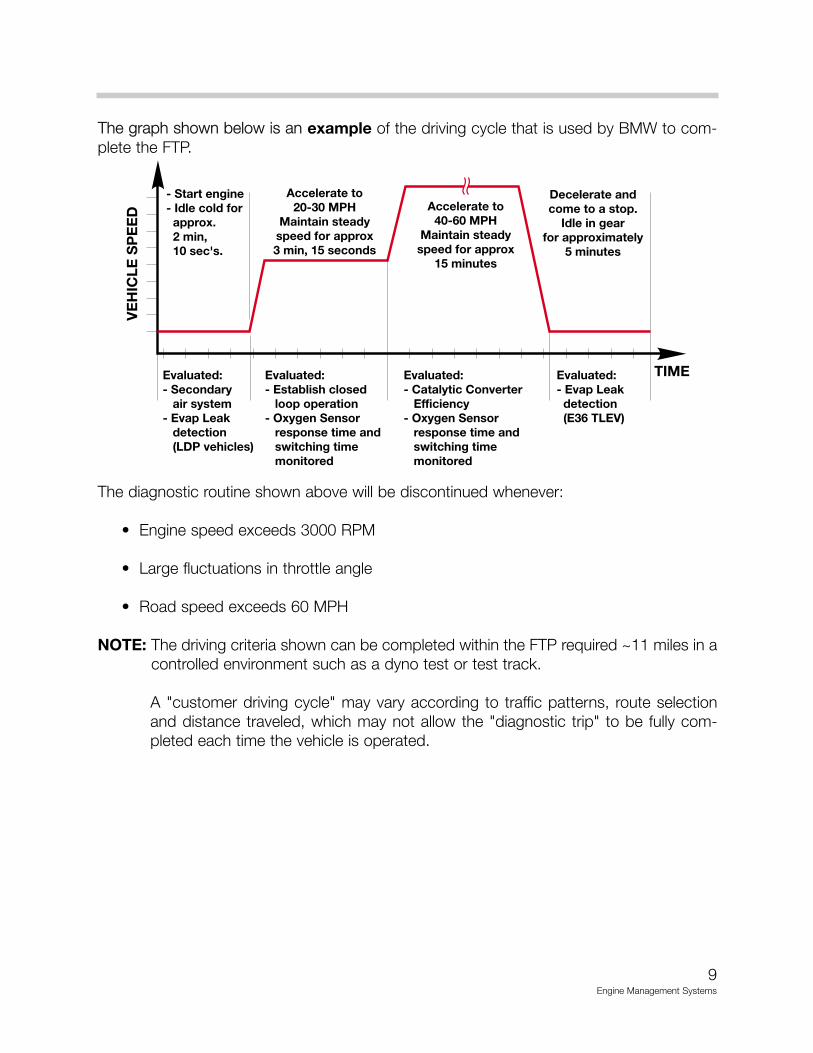
The graph shown below is an example of the driving cycle that is used by BMW to com-plete the FTP.
The diagnostic routine shown above will be discontinued whenever:
• Engine speed exceeds 3000 RPM
• Large fluctuations in throttle angle
• Road speed exceeds 60 MPH
NOTE: The driving criteria shown can be completed within the FTP required ~11 miles in acontrolled environment such as a dyno test or test track.
A "customer driving cycle" may vary according to traffic patterns, route selectionand distance traveled, which may not allow the "diagnostic trip" to be fully com-pleted each time the vehicle is operated.
9Engine Management Systems
OBD II FUNCTION: "CHECK ENGINE" (MIL) LIGHT
In conjunction with the CARB/OBD II regulations the "CHECK ENGINE" light (also referred toas the Malfunction Indicator Light - MIL) is to be illuminated:
• Upon the completion of the second consecutive driving cycle where the previously fault-ed system is monitored again and the emissions relevant fault is again present.
• Immediately if a catalyst damaging fault occurs (see Misfire Detection).
The illumination of the check engine light is performed in accordance with the Federal TestProcedure (FTP) which requires the lamp to be illuminated when:
• A malfunction of a component that can affect the emission performance of the vehicleoccurs and causes emissions to exceed 1.5 times the standards required by the (FTP).
• Manufacturer-defined specifications are exceeded.
• An implausible input signal is generated.
• Catalyst deterioration causes HC-emissions to exceed a limit equivalent to 1.5 times thestandard (FTP).
• Misfire faults occur.
• A leak is detected in the evaporative system
• The oxygen sensors observe no purge flow from the purge valve/evaporative system.
• Engine control module fails to enter closed-loop operation within a specified time interval.
• Engine control or automatic transmission control enters a "limp home" operating mode.
• Key is in the "ignition" on position before cranking (Bulb Check Function).
Within the BMW system the illumination of the check engine light is performed in accor-dance with the regulations set forth in CARB mail-out 1968.1 and as demonstrated via theFederal Test Procedure (FTP). The following information provides several examples of whenand how the "Check Engine" Light is illuminated based on the "customer drive cycle" (DC):
10Engine Management Systems
11Engine Management Systems
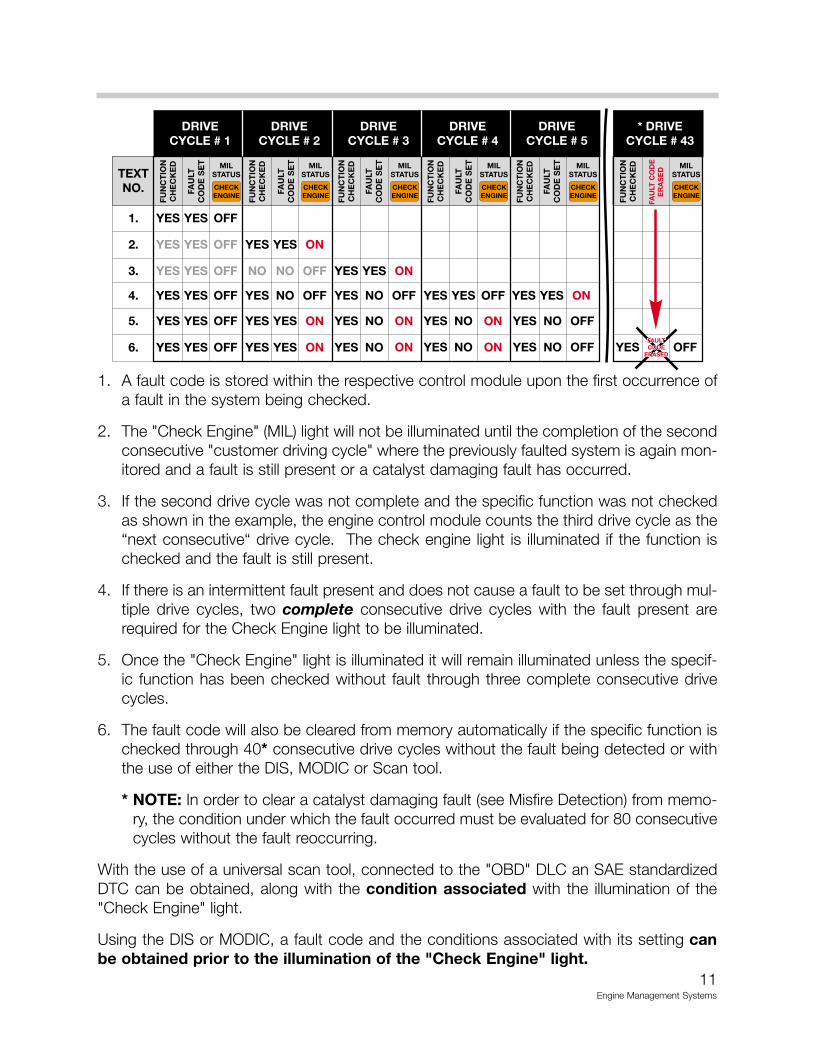
1. A fault code is stored within the respective control module upon the first occurrence ofa fault in the system being checked.
2. The "Check Engine" (MIL) light will not be illuminated until the completion of the secondconsecutive "customer driving cycle" where the previously faulted system is again mon-itored and a fault is still present or a catalyst damaging fault has occurred.
3. If the second drive cycle was not complete and the specific function was not checkedas shown in the example, the engine control module counts the third drive cycle as the“next consecutive“ drive cycle. The check engine light is illuminated if the function ischecked and the fault is still present.
4. If there is an intermittent fault present and does not cause a fault to be set through mul-tiple drive cycles, two complete consecutive drive cycles with the fault present arerequired for the Check Engine light to be illuminated.
5. Once the "Check Engine" light is illuminated it will remain illuminated unless the specif-ic function has been checked without fault through three complete consecutive drivecycles.
6. The fault code will also be cleared from memory automatically if the specific function ischecked through 40* consecutive drive cycles without the fault being detected or withthe use of either the DIS, MODIC or Scan tool.
* NOTE: In order to clear a catalyst damaging fault (see Misfire Detection) from memo-ry, the condition under which the fault occurred must be evaluated for 80 consecutivecycles without the fault reoccurring.
With the use of a universal scan tool, connected to the "OBD" DLC an SAE standardizedDTC can be obtained, along with the condition associated with the illumination of the"Check Engine" light.
Using the DIS or MODIC, a fault code and the conditions associated with its setting canbe obtained prior to the illumination of the "Check Engine" light.
OBD II DIAGNOSTIC TROUBLE CODES (DTC)
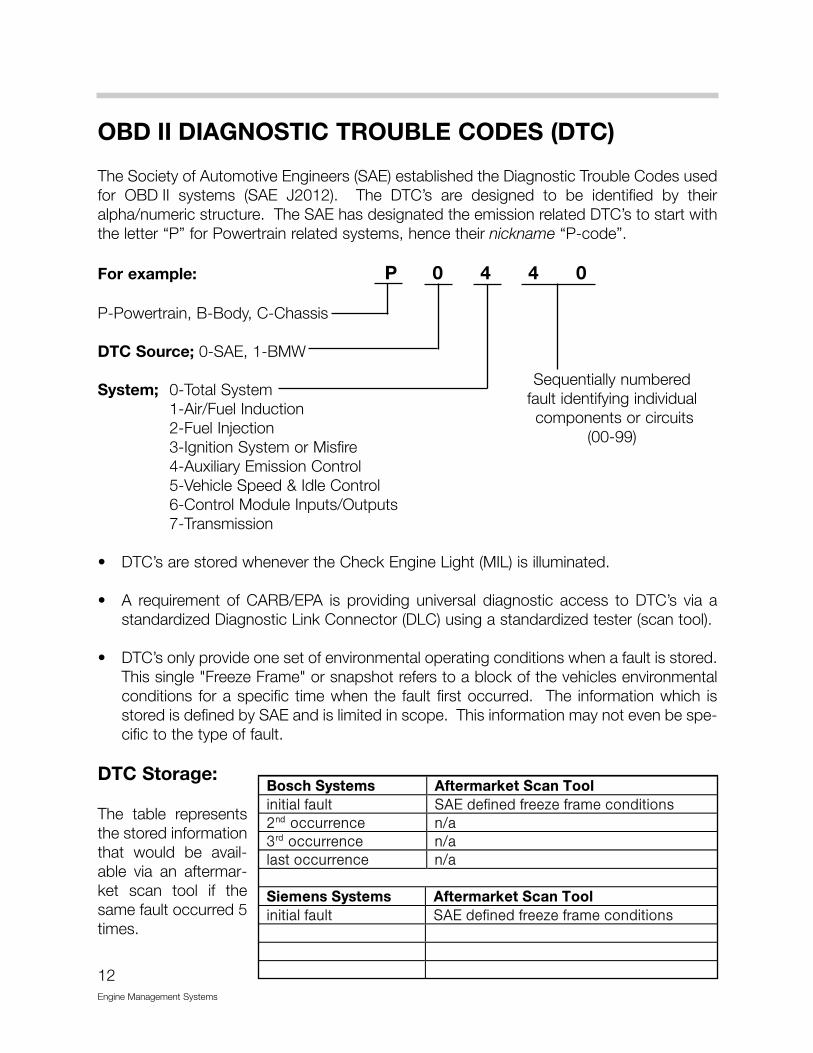
The Society of Automotive Engineers (SAE) established the Diagnostic Trouble Codes usedfor OBD II systems (SAE J2012). The DTC’s are designed to be identified by theiralpha/numeric structure. The SAE has designated the emission related DTC’s to start withthe letter “P” for Powertrain related systems, hence their nickname “P-code”.
For example: P 0 4 4 0
P-Powertrain, B-Body, C-Chassis
DTC Source; 0-SAE, 1-BMW
System; 0-Total System1-Air/Fuel Induction2-Fuel Injection3-Ignition System or Misfire4-Auxiliary Emission Control5-Vehicle Speed & Idle Control6-Control Module Inputs/Outputs7-Transmission
• DTC’s are stored whenever the Check Engine Light (MIL) is illuminated.
• A requirement of CARB/EPA is providing universal diagnostic access to DTC’s via astandardized Diagnostic Link Connector (DLC) using a standardized tester (scan tool).
• DTC’s only provide one set of environmental operating conditions when a fault is stored.This single "Freeze Frame" or snapshot refers to a block of the vehicles environmentalconditions for a specific time when the fault first occurred. The information which isstored is defined by SAE and is limited in scope. This information may not even be spe-cific to the type of fault.
DTC Storage:
The table representsthe stored informationthat would be avail-able via an aftermar-ket scan tool if thesame fault occurred 5times.
12Engine Management Systems
����89��:���� �#;��� �<���8 ��&���������������/�� �01����������2�����������������#����/��� ��+���%����/��� ��+���������/��� ��+�
��������:���� �#;��� �<���8 ��&���������������/�� �01����������2����������������� ��� ��� �
Sequentially numbered fault identifying individualcomponents or circuits
(00-99)

13Engine Management Systems
Scan Tool Connection (to 6/00)
Starting with the 1995 750iL, and soonafter on all 1996 model year BMW vehi-cles, a separate OBD II Diagnostic LinkConnector (DLC) was added.
The DLC provides access for an aftermar-ket scan tool to all emission related controlsystems (DME, AGS/EGS and EML). Thisdiagnostic communication link uses theexisting TXD II circuit in the vehicle througha separate circuit on the DLC when the 20pin cap is installed.
Scan Tool Display
Example: A fault was induced into a 1998750iL by removing the wire connector from AirMass Meter. Using an aftermarket scan toolthe following information can be displayed:
341*"��5�(6����3�0���(7 8'#�������� /�������3���7 '99:!'!! ���/���/��
����������/���������������
�� ��5�; <5��=��<51��
3�� :!'!!�� *4 ��0:3 .!$�5:����� '-!�< ��4����0:3 !��:��� *4 ����13 %".><<(���0�1��' ��<<(���0�1��# ��00��<��' !"!>����<��' '"->00��<��# !"!>����<��# %"'>

20 PIN DIAGNOSTIC SOCKET DELETION
Model: E39,E46,E52,E53
Production Date: E46 from 6/00E39,E52,E53 from 9/00
For model year 2001 the E39, E46 and E53 will eliminate the 20 pin diagnostic connectorfrom the engine compartment. The 16 pin OBD II connector located inside the vehicle willbe the only diagnosis port.
The E38 and Z3 will continue to use the 20 pin connector.
The 16 pin OBD II connector has been in allBMWs since 1996 to comply with OBD IIregulations requiring a standardized diagnosticport.
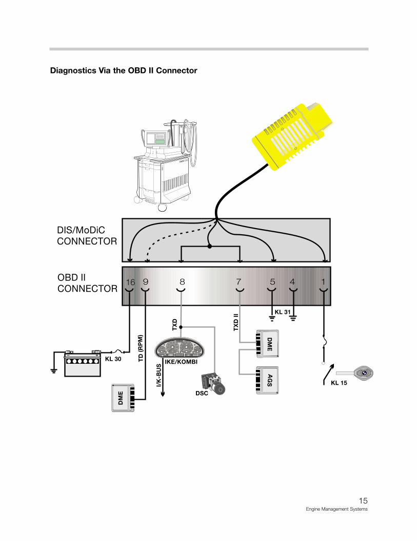
Previously before 2001, only emissions relevantdata could be extracted from the OBD IIconnector because it did not provide access toTXD (D-bus). The TXD line is connected to pin8 of the OBD II connector on vehicles withoutthe 20 pin diagnostic connector.
The cap to the OBD II connector contains abridge that links KL 30 to TXD and TXD II. Thisis to protect the diagnostic circuit integrity andprevent erroneous faults.
The OBD II connector is located in the driversfootwell to the left of the steering column ofE39, E46 and E53 vehicles.
14Engine Management Systems
15Engine Management Systems
- +
UNLEADED GASOLINE ONLY
0
12
20
km/h
MPH
1/minx1000
40
60
80
100120 140
160
180
200
220
240
1
0
2
3 4
5
6
7503020 1512
20
40
60
80100
120
14011
miles BRAKE ABS
16 9 8 7 5 4 1
DME
DME
AGS
I/K-BUS
IKE/KOMBI
DSC
KL 15
KL 30 TD(RPM)
TXD
TXDII
OBD II
CONNECTOR
DIS/MoDiC
CONNECTOR
KL 31
BMWDIS
BMW DIS
BM
WD
IS
BM
WD
IS
DSC III
kjhsdfkhsdflkhsdlkfjhlkjghkg
lkdkfljdflkjdsfljdslfjldskjflkjdflk
ldsflsdfklhdsfhsdfhsdkhfkhsdf
kldjfkljdfkjdskfkjdskfjkljdfkldsfk
kjsdfkljsdfkdsfkjdsfkljsdfkjds
ldjsfklkjsdfkldsjfkdsjfkdsfkdfklk
Diagnostics Via the OBD II Connector
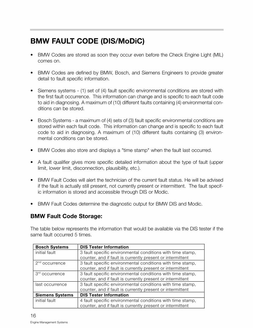
BMW FAULT CODE (DIS/MoDiC)
• BMW Codes are stored as soon they occur even before the Check Engine Light (MIL)comes on.
• BMW Codes are defined by BMW, Bosch, and Siemens Engineers to provide greaterdetail to fault specific information.
• Siemens systems - (1) set of (4) fault specific environmental conditions are stored withthe first fault occurrence. This information can change and is specific to each fault codeto aid in diagnosing. A maximum of (10) different faults containing (4) environmental con-ditions can be stored.
• Bosch Systems - a maximum of (4) sets of (3) fault specific environmental conditions arestored within each fault code. This information can change and is specific to each faultcode to aid in diagnosing. A maximum of (10) different faults containing (3) environ-mental conditions can be stored.
• BMW Codes also store and displays a "time stamp" when the fault last occurred.
• A fault qualifier gives more specific detailed information about the type of fault (upperlimit, lower limit, disconnection, plausibility, etc.).
• BMW Fault Codes will alert the technician of the current fault status. He will be advisedif the fault is actually still present, not currently present or intermittent. The fault specif-ic information is stored and accessible through DIS or Modic.
• BMW Fault Codes determine the diagnostic output for BMW DIS and Modic.
BMW Fault Code Storage:
The table below represents the information that would be available via the DIS tester if thesame fault occurred 5 times. ����89��:����� !��&����!�;��� ��������������/��� %���/�������������������������������?�������������,�
�/���,����������/������/���������������������������#����/���� %���/�������������������������������?�������������,�
�/���,����������/������/���������������������������%����/���� %���/�������������������������������?�������������,�
�/���,����������/������/���������������������������������/���� %���/�������������������������������?�������������,�
�/���,����������/������/���������������������������������:����� !��&����!�;��� ��������������/��� &���/�������������������������������?�������������,�
�/���,����������/������/���������������������������
16Engine Management Systems

SIEMENS ENGINE MANAGEMENT SYSTEM
This Siemens system is designated as MS42.0.
Siemens MS42.0 was developed tomeet the needs of Low EmissionVehicle (LEV) compliancy and OBDII. This system also includes controlof the Motor-driven Throttle Valve(MDK).
The ECM uses a pc-board single-processor control unit in the newSKE housing. Mounted in the E-Box(next to brake master cylinder). TheMS 42.0 ECM is flash programma-ble as seen with previous systems.
ECM hardware includes:
Modular plug connectors featuring 5 connectors in the SKE housing with 134 pins.
• Connector 1 = Supply voltages and grounds• Connector 2 = Peripheral signals (oxygen sensors, CAN, etc.)• Connector 3 = Engine signals• Connector 4 = Vehicle signals• Connector 5 = Ignition signals
Special features:
• Flash EPROM which is adaptable to severalM52 LEV engines and has the capability tobe programmed up to 13 times
• Once a control unit is installed and coded to a vehicle it cannot be swapped with anoth-er vehicle for diagnosing or replacement (because of EWS 3.3). A new ECM must beinstalled if necessary.
17Engine Management Systems

MS 42.0 I-P-O
18Engine Management Systems
KL 15
MEMORY POWER
AUX KL 31
MAIN KL 31ECMRELAY
CRANKSHAFTPOSITION SENSOR
OPERATING POWER
IGNITION MONITOR
E46IHKA K-BUS
ROLLING CODE
ECM RELAYCONTROL
FUEL PUMP RELAY CONTROL
AC COMPRESSORRELAY CONTROL
SECONDARY AIR INJECTIONAIR PUMP RELAY CONTROL
AIRINJ.SOL.
RUNLOSSSOL.
EXHAUST VANOS SOLENOID
INTAKE VANOS SOLENOID
IDLE CONTROL VALVE
PRE-CAT(2X)
POST-CAT(2X)
02 SENSOR HEATING
IGNITION COILS CONTROL (6X)
OBD II
DIAGNOSIS
DIS
CANTCM
P
M
E46M52 TU
MS42.0
CAMSHAFT POSITION SENSOR (2)
KNOCKSENSORS
ENGINE TEMPERATURE
2X 2XPRE & POSTCAT CONV.O2 SENSOR
MONITORING
THROTTLEPOSITION
AIRMASS SIGNAL
INTAKEAIRTEMP
OUTPUT STAGE
PURGE VALVE CONTROL
INTAKE JET PUMP SOLENOID VALVE
SEQUENTIAL FUEL INJECTOR CONTROL (6X)
OIL TEMPSENSOR
MDKMOTOR DRIVEN THROTTLE VALVE
MDK
RESONANCE-TURBULENCE INTAKE SYSTEM
COMPRESSOR CLUTCH
MAP-CONTROLLED
HEATED THERMOSTAT
THROTTLEPOSITION
(DK)
ABS/ASC
VEHICLE SPEED INPUTABS/ASC
ELECTRIC FAN
LEAKAGE DIAGNOSIS
PUMP
+LEAKAGE DIAGNOSIS PUMP+
M
RADIATOR OUTLETTEMPERATURE SENSOR
I/O
MFL BUTTON PAD
CLUTCH SWITCHBRAKE LIGHT SWITCH
BRAKE LIGHT TEST SWITCH
CAN
CHECKCHECKENGINEENGINE UNLEADED GASOLINE ONLY
0
1 2
20
km/h
MPH
1/minx1000
40
60
80
100120 140
160180
200
220
240
1
0
23 4
5
6
7503020 1512
20
40
6080
100
120
1401 1
UNLEADED GASOLINE ONLY
0
1 2
20
km/h
MPH
1/minx1000
40
60
80
100120 140
160180
200
220
240
1
0
23 4
5
6
7503020 1512
20
40
6080
100
120
1401 1
19Engine Management Systems
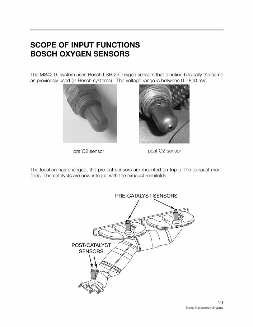
SCOPE OF INPUT FUNCTIONSBOSCH OXYGEN SENSORS
The MS42.0 system uses Bosch LSH 25 oxygen sensors that function basically the sameas previously used (in Bosch systems). The voltage range is between 0 - 800 mV.
The location has changed, the pre-cat sensors are mounted on top of the exhaust mani-folds. The catalysts are now integral with the exhaust manifolds.
PRE-CATALYST SENSORS
POST-CATALYSTSENSORS
pre O2 sensor post O2 sensor
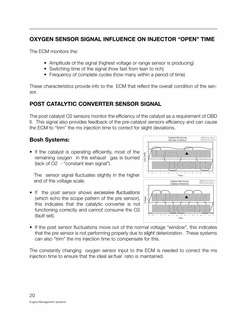
OXYGEN SENSOR SIGNAL INFLUENCE ON INJECTOR “OPEN” TIME
The ECM monitors the:
• Amplitude of the signal (highest voltage or range sensor is producing)• Switching time of the signal (how fast from lean to rich)• Frequency of complete cycles (how many within a period of time)
These characteristics provide info to the ECM that reflect the overall condition of the sen-sor.
POST CATALYTIC CONVERTER SENSOR SIGNAL
The post catalyst O2 sensors monitor the efficiency of the catalyst as a requirement of OBDII. This signal also provides feedback of the pre-catalyst sensors efficiency and can causethe ECM to “trim” the ms injection time to correct for slight deviations.
Bosh Systems:
• If the catalyst is operating efficiently, most of theremaining oxygen in the exhaust gas is burned(lack of O2 - “constant lean signal”).
The sensor signal fluctuates slightly in the higherend of the voltage scale.
• If the post sensor shows excessive fluctuations(which echo the scope pattern of the pre sensor),this indicates that the catalytic converter is notfunctioning correctly and cannot consume the O2(fault set).
• If the post sensor fluctuations move out of the normal voltage “window”, this indicatesthat the pre sensor is not performing properly due to slight deterioration. These systemscan also “trim” the ms injection time to compensate for this.
The constantly changing oxygen sensor input to the ECM is needed to correct the msinjection time to ensure that the ideal air/fuel ratio is maintained.
20Engine Management Systems
�������������������� ����������������
!
'
#
%
&
$
-
! !"$ ' '"$ # #"$ % %"$ & &"$ $ $"$ - -"$ ) )"$ @
���
���
1*�
:�����"�0����:�������"�0����
�����������������������������3�����
!
'
#
%
&
$
-
! !"$ ' '"$ # #"$ % %"$ & &"$ $ $"$ - -"$ ) )"$ @
���
�����
:�������"�0����:�����"�0����
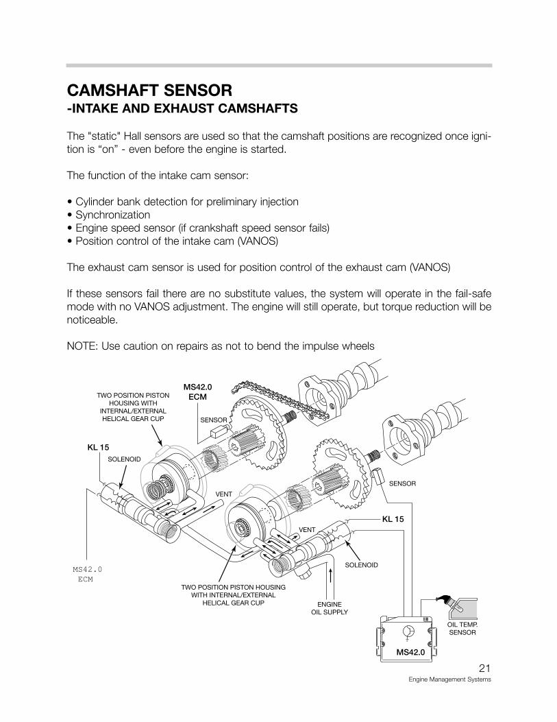
CAMSHAFT SENSOR-INTAKE AND EXHAUST CAMSHAFTS
The "static" Hall sensors are used so that the camshaft positions are recognized once igni-tion is “on” - even before the engine is started.
The function of the intake cam sensor:
• Cylinder bank detection for preliminary injection• Synchronization• Engine speed sensor (if crankshaft speed sensor fails)• Position control of the intake cam (VANOS)
The exhaust cam sensor is used for position control of the exhaust cam (VANOS)
If these sensors fail there are no substitute values, the system will operate in the fail-safemode with no VANOS adjustment. The engine will still operate, but torque reduction will benoticeable.
NOTE: Use caution on repairs as not to bend the impulse wheels
21Engine Management Systems
KL 15
KL 15
MS42.0
SOLENOID
OIL TEMP.SENSOR
TWO POSITION PISTON HOUSINGWITH INTERNAL/EXTERNAL
HELICAL GEAR CUP
TWO POSITION PISTONHOUSING WITH
INTERNAL/EXTERNALHELICAL GEAR CUP
ENGINEOIL SUPPLY
VENT
VENT
SOLENOID
SENSOR
SENSOR
MS42.0ECM
MS42.0ECM
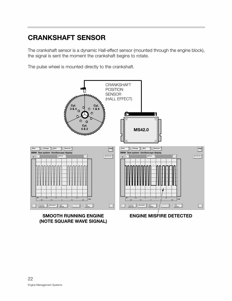
CRANKSHAFT SENSOR
The crankshaft sensor is a dynamic Hall-effect sensor (mounted through the engine block),the signal is sent the moment the crankshaft begins to rotate.
The pulse wheel is mounted directly to the crankshaft.
22Engine Management Systems

MISFIRE DETECTION
As part of the CARB/OBD regulations the engine control module must determine if misfireis occurring and also identify the specific cylinder(s) and the severity of the misfire event,and whether it is emissions relevant or catalyst damaging. In order to accomplish thesetasks the control module monitors the crankshaft for acceleration losses during firing seg-ments of each cylinder based on firing order.
Misfire Detection Example: M52 (6 Cyl.) with Siemens System
The misfire/engine roughness calculation is derived from the differences in the period dura-tion (T) of individual increment gear segments. Each segment period consist of an angularrange of 120° crank angle that starts 78° before Top Dead Center (TDC).
Increment gear wheel segment period measurement:
• If the combustion process in all cylinders is functioning correctly, the period duration ofeach segment will be identical (i.e. T0 = T1 = T2 = T3 = T4 = T5).
• If a misfire is encountered in a cylinder, the period duration (T) of that cylinder will beextended by a fraction of a millisecond (i.e. T3 > T0, T1, T2, T4, T5).
• All measured values of T are evaluated within the DME, corrected based on sensor adap-tation and compared to a set of predetermined values that are dependent on enginespeed, load and engine temperature.
If the expected period duration is greater than the permissible value a misfire fault for theparticular cylinder is stored in the fault memory of the DME. Depending on the level of mis-fire rate measured the control unit will illuminate the "Check Engine" light, may cut-off fuelto the particular cylinder and may switch lambda operation to open-loop. All misfire faultsare weighted to determine if the misfire is emissions relevant or catalyst damaging.
23Engine Management Systems
'#!��1
�3�! �3�' �3�# �3�% �3�& �3�$ �3�!
)@������3�
��A% ��A# ��A' �� ��B' ��B# ��B%
��������������������
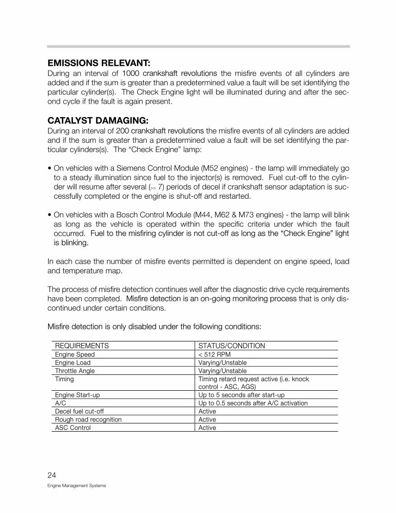
EMISSIONS RELEVANT:During an interval of 1000 crankshaft revolutions the misfire events of all cylinders areadded and if the sum is greater than a predetermined value a fault will be set identifying theparticular cylinder(s). The Check Engine light will be illuminated during and after the sec-ond cycle if the fault is again present.
CATALYST DAMAGING:During an interval of 200 crankshaft revolutions the misfire events of all cylinders are addedand if the sum is greater than a predetermined value a fault will be set identifying the par-ticular cylinders(s). The “Check Engine” lamp:
• On vehicles with a Siemens Control Module (M52 engines) - the lamp will immediately goto a steady illumination since fuel to the injector(s) is removed. Fuel cut-off to the cylin-der will resume after several (>> 7) periods of decel if crankshaft sensor adaptation is suc-cessfully completed or the engine is shut-off and restarted.
• On vehicles with a Bosch Control Module (M44, M62 & M73 engines) - the lamp will blinkas long as the vehicle is operated within the specific criteria under which the faultoccurred. Fuel to the misfiring cylinder is not cut-off as long as the “Check Engine” lightis blinking.
In each case the number of misfire events permitted is dependent on engine speed, loadand temperature map.
The process of misfire detection continues well after the diagnostic drive cycle requirementshave been completed. Misfire detection is an on-going monitoring process that is only dis-continued under certain conditions.
Misfire detection is only disabled under the following conditions:
24Engine Management Systems
REQUIREMENTS STATUS/CONDITIONEngine Speed < 512 RPMEngine Load Varying/UnstableThrottle Angle Varying/UnstableTiming Timing retard request active (i.e. knock
control - ASC, AGS)Engine Start-up Up to 5 seconds after start-upA/C Up to 0.5 seconds after A/C activationDecel fuel cut-off ActiveRough road recognition ActiveASC Control Active
25E
ngine Managem
ent System
s
OBD II - Misfire Faults<14��3���:� � �
:�0046���<1(�� ��40<45��<<���+���1�4�
�������� ���C� �������C��������������������������
:����� ����������������?�+��������2��������
�������������������
�����/����������D/������ 1�
�����7��""���������������+���C�
�������������������
�������������/���/����/��������?
</������/� �/���/��,�����/��������? �������C�����"�'A%���������������
�/���������������+����C� �������C�����"�'A%���������������
�/���/��,�����/���/����/��������?�����������
�������C�����"�'A%���������������
��C�����/��������� �������C�����"�'A%���������������
����/����/������������������������
�������C�����"�'A%���������������
�/��������������������� �������C�����"�'A%���������������
�/�����C����� �������C�����"�'A%���������������
�������D���/��������/����C�����
�������C�����"�'A%���������������
?��������/�����C �������C��������������������������
</� ������������������� ���������������������������������������� �����������������
����������� ����������/���������� �����������������C:/������� ��������������/���/
���������������������/��������������C�
���C���/�����C��������� ���������������C������+������?��
����������/�������������������������
�����������
�������?������� ������������������?��������� �����������������?������������������?��
�����������
����?������������������������ ���/�����C�����/����
������������C������������������C
3�� ������������������+��D���� ����������
<14��3���:� � �
:�0046���<1(�� ��40<45��<<���+���1�4�
0���C���/� ������������������� ��������������������������� �����������������������+�/�����C� �������������
����������+�/�����C���/������C���/����������C� ����������������������������� �������C�����������
���������������
���������������������������,����+�/����/���������������������C�������������������� �������C�����������
���������������0���C���/�������� ?�,�?������������/� �������C�����������
������������������C� �������������
4������������ �����������,������ ������������������������������ �������� �����������������
������C���/� �������������������/������ ����������������������?�������������� �����������������
4�D����� ��� ����������� ������������������
��C��� ������������������
��������/�� ����������������������+���������� �����������������
4�D����������� �������� �����������������������C���/� �������������������/������ ����������������������?�������������� �����������������
4���C������������C� ����C����/�,�/����������C����""���D���������
4���C+����/������� �������/����/�������C� �������C��������������������������
�/������������� ������������������
�����7����C�������/����������C���������
�������C��������������������������

26Engine Management Systems
MASS AIR FLOW SENSOR HFM
The Siemens mass air flow sensor is functionally the same as on previous systems. Thenew designation - 2 Type B simply indicates that it is smaller in design.
SCOPE OF OUTPUT FUNCTIONS
VANOS CONTROL
With the introduction of double VANOS, the valve timing is changed on both the intake andthe exhaust camshafts.
Double VANOS provides the following benefits:
• Torque increase in the low to mid (1500 - 2000 RPM) range without power loss in theupper RPM range.
• Less incomplete combustion when idling due to less camshaft overlap (also improvesidle speed characteristics).
• Internal exhaust gas recirculation (EGR) in the part load range (reduces NOx and post-combustion of residual gasses in the exhaust)
• Rapid catalyst warm up and lower “raw” emissions after cold start.
• Reduction in fuel consumption
Double VANOS consists of the following parts:
• Intake and exhaust camshafts with helical gear insert
• Sprockets with adjustable gears
• VANOS actuators for each camshaft
• 2 three-way solenoid switching valves
• 2 impulse wheels for detecting camshaft position
• 2 camshaft position sensors (Hall effect)
The “initial” timing is set by gear positioning (refer to the Repair Instructions for details) andthe chain tensioner. As with the previous VANOS, the hydraulically controlled actuatorsmove the helical geared cups to regulate camshaft timing. The angled teeth of the helicalgears cause the pushing movement of the helical cup to be converted into a rotationalmovement. This rotational movement is added to the turning of the camshafts and causethe camshafts to “advance” or “retard”. The adjustment rate is dependent oil temperature,oil pressure, and engine RPM.
27Engine Management Systems
28Engine Management Systems
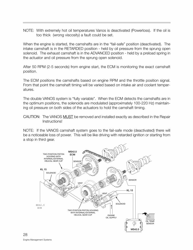
NOTE: With extremely hot oil temperatures Vanos is deactivated (Powerloss). If the oil istoo thick (wrong viscosity) a fault could be set.
When the engine is started, the camshafts are in the “fail-safe” position (deactivated). Theintake camshaft is in the RETARDED position - held by oil pressure from the sprung opensolenoid. The exhaust camshaft is in the ADVANCED position - held by a preload spring inthe actuator and oil pressure from the sprung open solenoid.
After 50 RPM (2-5 seconds) from engine start, the ECM is monitoring the exact camshaftposition.
The ECM positions the camshafts based on engine RPM and the throttle position signal.From that point the camshaft timing will be varied based on intake air and coolant temper-atures.
The double VANOS system is “fully variable”. When the ECM detects the camshafts are inthe optimum positions, the solenoids are modulated (approximately 100-220 Hz) maintain-ing oil pressure on both sides of the actuators to hold the camshaft timing.
CAUTION: The VANOS MUST be removed and installed exactly as described in the RepairInstructions!
NOTE: If the VANOS camshaft system goes to the fail-safe mode (deactivated) there willbe a noticeable loss of power. This will be like driving with retarded ignition or starting froma stop in third gear.
KL 15
KL 15
MS42.0
SOLENOID
OIL TEMP.SENSOR
TWO POSITION PISTON HOUSINGWITH INTERNAL/EXTERNAL
HELICAL GEAR CUP
TWO POSITION PISTONHOUSING WITH
INTERNAL/EXTERNALHELICAL GEAR CUP
ENGINEOIL SUPPLY
VENT
VENT
SOLENOID
SENSOR
SENSOR
MS42.0ECM
MS42.0ECM
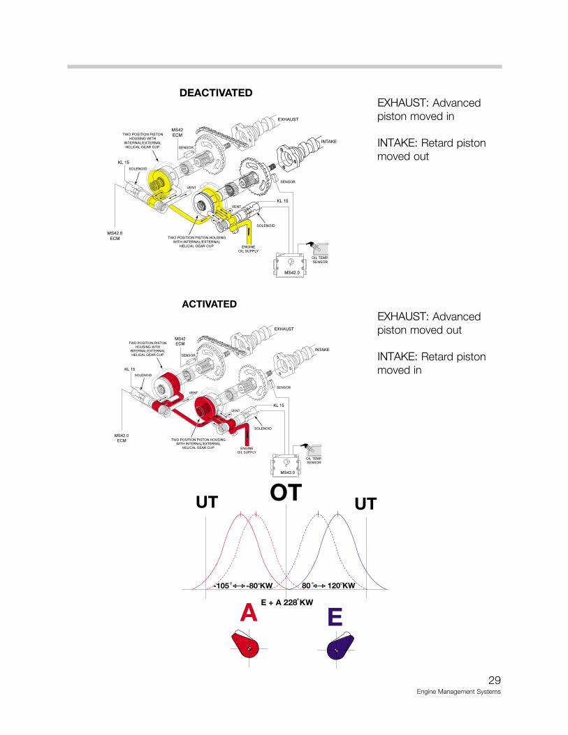
EXHAUST: Advancedpiston moved in
INTAKE: Retard pistonmoved out
EXHAUST: Advancedpiston moved out
INTAKE: Retard pistonmoved in
29Engine Management Systems
DEACTIVATED
�����
�����
����
��� ����
����� ���� ����
������������������������������������ ����� �� �����
� ������� ������
���������������������������������
��� ����� �� ������ ������� ������
���� �����������
� ��
� ��
��� ����
� ����
� ����
���� ��
������
�����
����� ��
ACTIVATED
�����
�����
����
��� ����
����� ���� ����
������������������������������������ ����� �� �����
� ������� ������
���������������������������������
��� ����� �� ������ ������� ������
���� �����������
� ��
� ��
��� ����
� ����
� ����
���� ��
������
�����
����� ��

The dual VANOS in conjunction with the variable intake manifold provides an additionalemission control feature.
Because of the improved combustion, the camshaft timing is adjusted for more overlap.The increased overlap supports internal exhaust gas recirculation (EGR) which reducestailpipe emissions and lowers fuel consumption.
During the part load engine range, the intake camshaft overlap opens the intake valve. Thisallows limited exhaust gas reflow the intake manifold.
The “internal” EGR reduces the cylinder temperature thus lowering NOx. This feature pro-vides EGR without the external hardware as seen on previous systems.
30Engine Management Systems
INLETTURBULENCE
IDLE AIR CONTROL VALVE
MDK
INT. EGR
CATALYSTCLOSE TO
ENGINE
SECONDARYAIR
INJECTION(AIR FILTER)
OUTLET-VANOS(228/80-105)
INLET-VANOS(228/80-120)

ELECTRIC FAN
The electric cooling fan is controlled by the ECM. The ECM uses a remote power outputfinal stage (mounted on the fan housing)
The power output stage receives power from a 50 amp fuse (located in glove box abovethe fuse bracket). The electric fan is controlled by a pulse width modulated signal from theECM.
The fan is activated based on the ECM calculation (sensing ratio) of:
• Coolant outlet temperature• Calculated (by the ECM) catalyst temperature• Vehicle speed• Battery voltage• Air Conditioning pressure (calculated by IHKA
and sent via the K-Bus to the ECM)
Activation of the electric fan:
When the vehicle is first started the fan is activated briefly (20% of maximum speed), thenit is switched off. This procedure is performed for diagnostic purposes.
The voltage generated by the fan when it slows down (it becomes a generator at this time)must meet the power output stages programmed criteria. This will confirm the RPM of thefan, if this is not met the signal wire from the output stage is switched to ground and a faultis set in memory.
NOTE: If the ECM indicates a fault check the fan for freedom of movement
After the initial test has been performed, the fan is brought up to the specified operatingspeed. At 10% (sensing ratio) the fan runs at 1/3 speed. At a sensing ratio of between 90-95% the fan is running at maximum speed. Below 10% or above 95% the fan is stationary.
The sensing ratio is suppressed by a hysteresis function, this prevents speed fluctuation.When the A/C is switched on, the electric fan is not immediately activated.
After the engine is switched off, the fan may continue to operate at varying speeds (basedon the ECM calculated catalyst temperature). This will cool the radiator down form a heatsurge (up to 10 minutes).
31Engine Management Systems
OUTPUT STAGE
MS42.0
POWER
RUNNING LOSSES
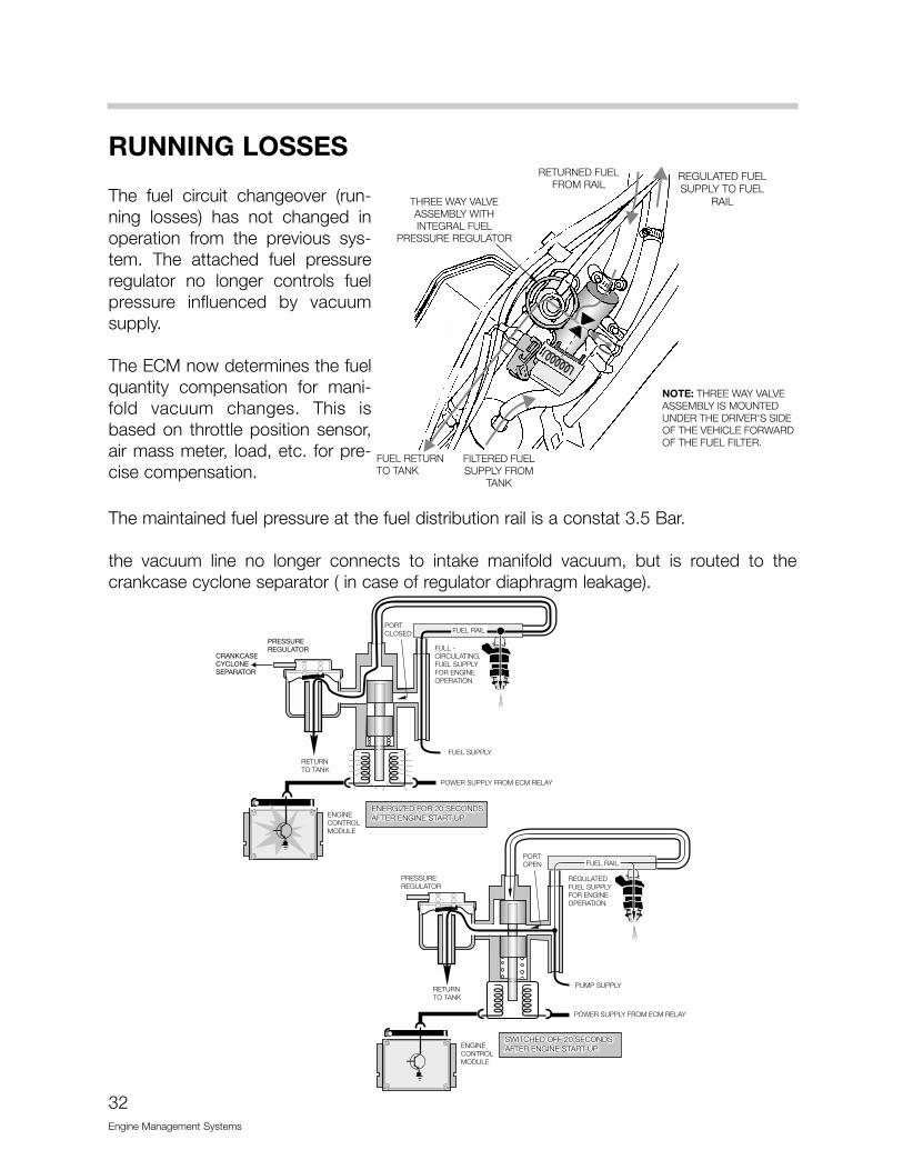
The fuel circuit changeover (run-ning losses) has not changed inoperation from the previous sys-tem. The attached fuel pressureregulator no longer controls fuelpressure influenced by vacuumsupply.
The ECM now determines the fuelquantity compensation for mani-fold vacuum changes. This isbased on throttle position sensor,air mass meter, load, etc. for pre-cise compensation.
The maintained fuel pressure at the fuel distribution rail is a constat 3.5 Bar.
the vacuum line no longer connects to intake manifold vacuum, but is routed to thecrankcase cyclone separator ( in case of regulator diaphragm leakage).
32Engine Management Systems
SECONDARY AIR INJECTION
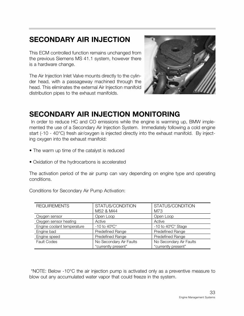
This ECM controlled function remains unchanged fromthe previous Siemens MS 41.1 system, however thereis a hardware change.
The Air Injection Inlet Valve mounts directly to the cylin-der head, with a passageway machined through thehead. This eliminates the external Air Injection manifolddistribution pipes to the exhaust manifolds.
SECONDARY AIR INJECTION MONITORINGIn order to reduce HC and CO emissions while the engine is warming up, BMW imple-
mented the use of a Secondary Air Injection System. Immediately following a cold enginestart (-10 - 40°C) fresh air/oxygen is injected directly into the exhaust manifold. By inject-ing oxygen into the exhaust manifold:
• The warm up time of the catalyst is reduced
• Oxidation of the hydrocarbons is accelerated
The activation period of the air pump can vary depending on engine type and operatingconditions.
Conditions for Secondary Air Pump Activation:
*NOTE: Below -10°C the air injection pump is activated only as a preventive measure toblow out any accumulated water vapor that could freeze in the system.
33Engine Management Systems
REQUIREMENTS STATUS/CONDITIONM52 & M44
STATUS/CONDITIONM73
Oxygen sensor Open Loop Open LoopOxygen sensor heating Active ActiveEngine coolant temperature -10 to 40ºC* -10 to 40ºC* StageEngine bad Predefined Range Predefined RangeEngine speed Predefined Range Predefined RangeFault Codes No Secondary Air Faults
“currently present”No Secondary Air Faults“currently present”
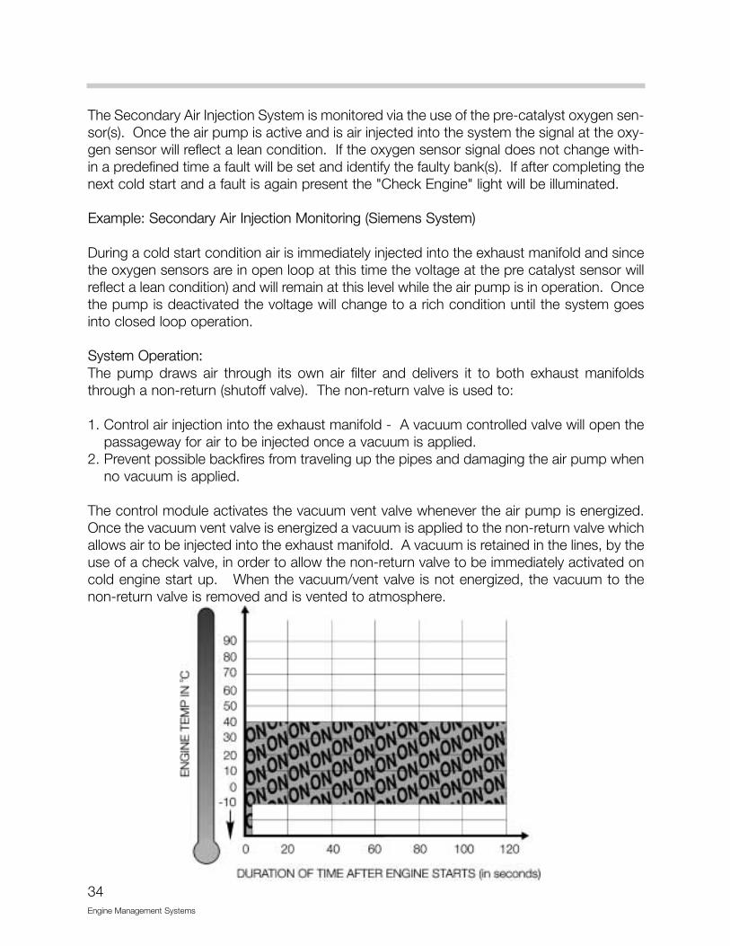
The Secondary Air Injection System is monitored via the use of the pre-catalyst oxygen sen-sor(s). Once the air pump is active and is air injected into the system the signal at the oxy-gen sensor will reflect a lean condition. If the oxygen sensor signal does not change with-in a predefined time a fault will be set and identify the faulty bank(s). If after completing thenext cold start and a fault is again present the "Check Engine" light will be illuminated.
Example: Secondary Air Injection Monitoring (Siemens System)
During a cold start condition air is immediately injected into the exhaust manifold and sincethe oxygen sensors are in open loop at this time the voltage at the pre catalyst sensor willreflect a lean condition) and will remain at this level while the air pump is in operation. Oncethe pump is deactivated the voltage will change to a rich condition until the system goesinto closed loop operation.
System Operation:The pump draws air through its own air filter and delivers it to both exhaust manifoldsthrough a non-return (shutoff valve). The non-return valve is used to:
1. Control air injection into the exhaust manifold - A vacuum controlled valve will open thepassageway for air to be injected once a vacuum is applied.
2. Prevent possible backfires from traveling up the pipes and damaging the air pump whenno vacuum is applied.
The control module activates the vacuum vent valve whenever the air pump is energized.Once the vacuum vent valve is energized a vacuum is applied to the non-return valve whichallows air to be injected into the exhaust manifold. A vacuum is retained in the lines, by theuse of a check valve, in order to allow the non-return valve to be immediately activated oncold engine start up. When the vacuum/vent valve is not energized, the vacuum to thenon-return valve is removed and is vented to atmosphere.
34Engine Management Systems

FUEL INJECTOR VALVES
The fuel injectors which are supplied by SiemensInject at an angle (dual cone spray pattern). The tipof the injector is fitted with a directional angle "plate"with dual outlets. The lower portion of the injectorbody is now jacketed in metal. The ECM control ofthe injectors remains unchanged from the previousSiemens MS41.1 system.
ENGINE/VEHICLE SPEED LIMITATION
For engine/vehicle speed limitation, the ECM willdeactivate injection for individual cylinders, allowinga smoother limitation transition. This prevents over-rev when the engine reaches maximum RPM (underacceleration), and limits top vehicle speed (approx.128 mph).
35Engine Management Systems
MS42.0CONTROLMODULE
36Engine Management Systems
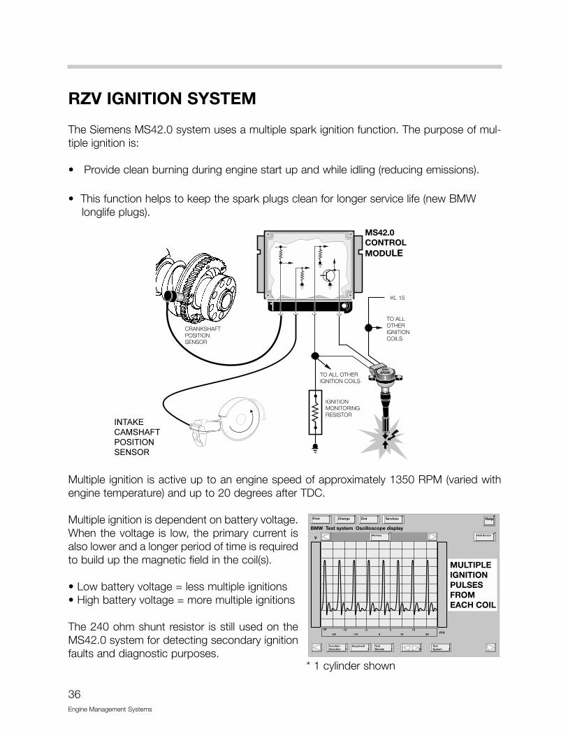
RZV IGNITION SYSTEM
The Siemens MS42.0 system uses a multiple spark ignition function. The purpose of mul-tiple ignition is:
• Provide clean burning during engine start up and while idling (reducing emissions).
• This function helps to keep the spark plugs clean for longer service life (new BMW longlife plugs).
Multiple ignition is active up to an engine speed of approximately 1350 RPM (varied withengine temperature) and up to 20 degrees after TDC.
Multiple ignition is dependent on battery voltage.When the voltage is low, the primary current isalso lower and a longer period of time is requiredto build up the magnetic field in the coil(s).
• Low battery voltage = less multiple ignitions• High battery voltage = more multiple ignitions
The 240 ohm shunt resistor is still used on theMS42.0 system for detecting secondary ignitionfaults and diagnostic purposes.
MS42.0CONTROLMODULE
����� ������������������ ����
* 1 cylinder shown
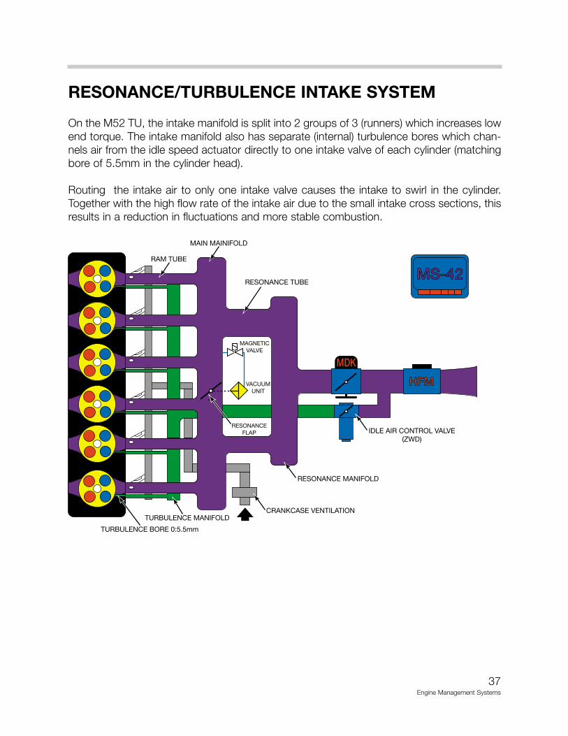
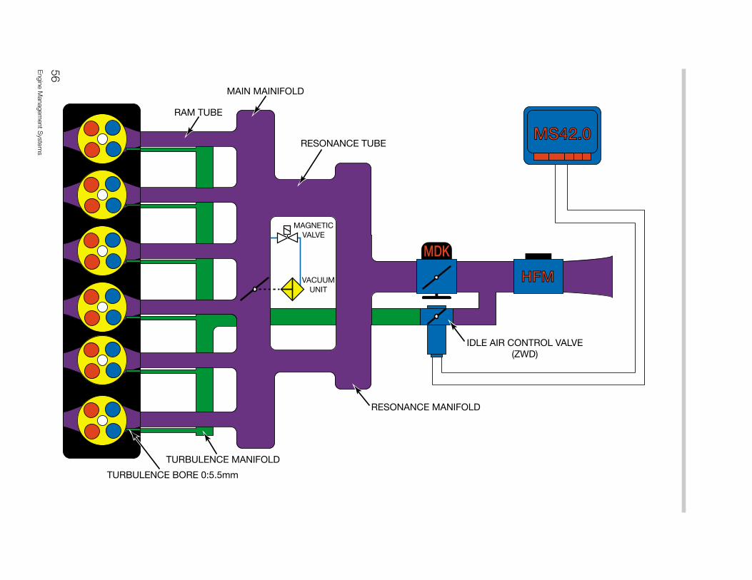
RESONANCE/TURBULENCE INTAKE SYSTEM
On the M52 TU, the intake manifold is split into 2 groups of 3 (runners) which increases lowend torque. The intake manifold also has separate (internal) turbulence bores which chan-nels air from the idle speed actuator directly to one intake valve of each cylinder (matchingbore of 5.5mm in the cylinder head).
Routing the intake air to only one intake valve causes the intake to swirl in the cylinder.Together with the high flow rate of the intake air due to the small intake cross sections, thisresults in a reduction in fluctuations and more stable combustion.
37Engine Management Systems
MDK
HFMHFM
MAGNETICVALVE
VACUUMUNIT
MS-42MS-42
RESONANCEFLAP
RAM TUBE
MAIN MAINIFOLD
RESONANCE TUBE
IDLE AIR CONTROL VALVE(ZWD)
RESONANCE MANIFOLD
CRANKCASE VENTILATIONTURBULENCE MANIFOLD
TURBULENCE BORE 0:5.5mm

RESONANCE SYSTEM
The resonance system provides increased engine torque at low RPM, as well as addition-al power at high RPM. Both of these features are obtained by using a resonance flap (inthe intake manifold) controlled by the ECM.
During the low to mid range rpm, the resonance flap is closed. This produces a long/sin-gle intake tube for velocity, which increases engine torque.
During mid range to high rpm, the resonance flap is open. This allows the intake air to pullthrough both resonance tubes, providing the air volume necessary for additional power atthe upper RPM range.
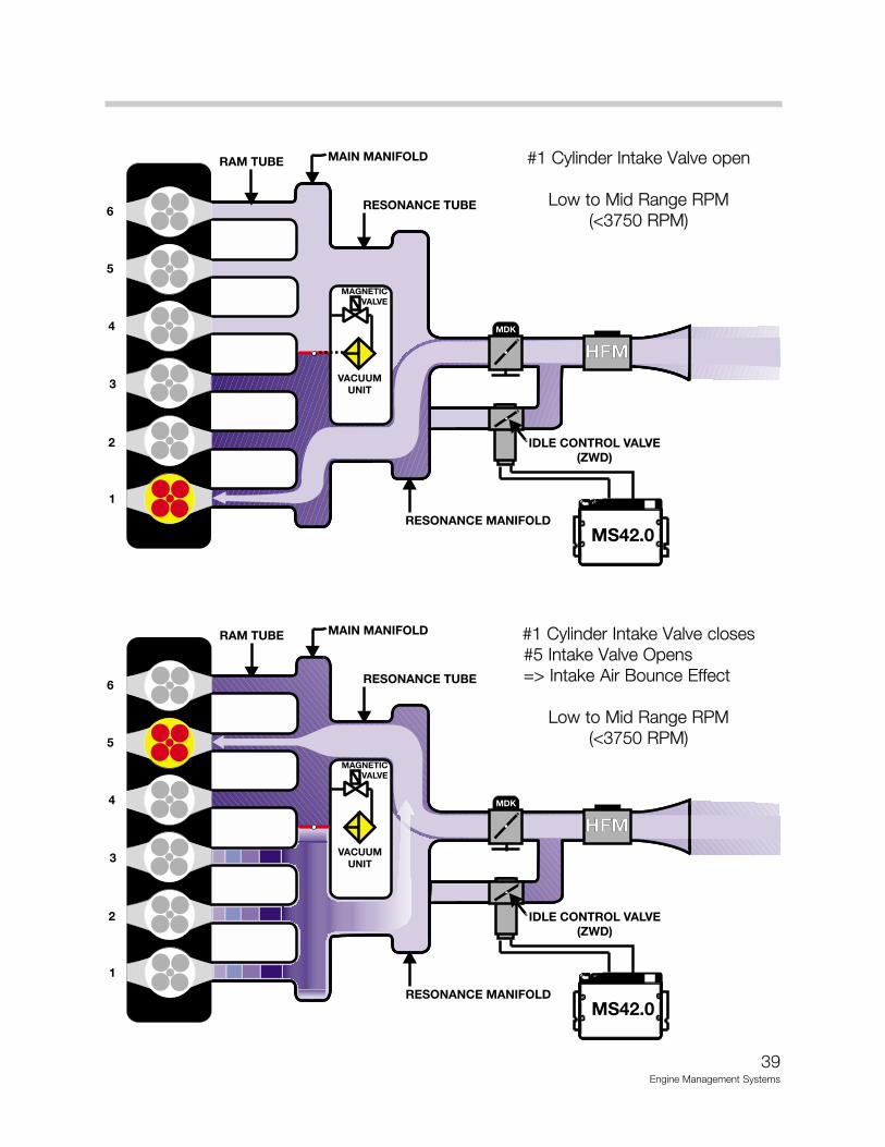
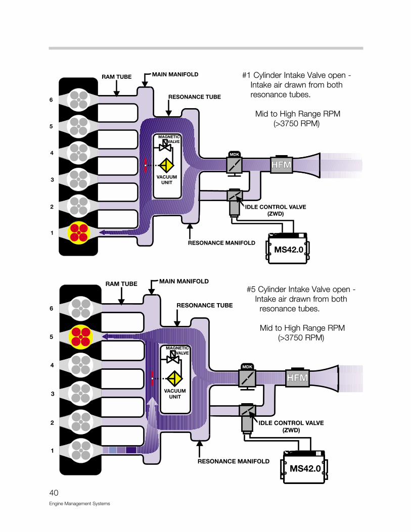
When the flap is closed , this creates another “dynamic” effect. For example, as the intakeair is flowing into cylinder #1, the intake valves will close. This creates a “roadblock” for thein rushing air. The air flow will stop and expand back (resonance wave back pulse) with thein rushing air to cylinder #5. The resonance “wave”, along with the intake velocity,enhances cylinder filling.
The ECM controls a solenoid valve for resonance flap activation. At speeds below 3750RPM, the solenoid valve is energized and vacuum supplied from an accumulator closesthe resonance flap. This channels the intake air through one resonance tube, but increas-es the intake velocity.
When the engine speed is greater than 4100 RPM (which varies slightly - temperature influ-enced), the solenoid is de-energized. The resonance flap is sprung open, allowing flowthrough both resonance tubes, increasing volume.
38Engine Management Systems
39Engine Management Systems
#1 Cylinder Intake Valve open
Low to Mid Range RPM (<3750 RPM)
#1 Cylinder Intake Valve closes#5 Intake Valve Opens => Intake Air Bounce Effect
Low to Mid Range RPM (<3750 RPM)
40Engine Management Systems
#1 Cylinder Intake Valve open -Intake air drawn from bothresonance tubes.
Mid to High Range RPM (>3750 RPM)
#5 Cylinder Intake Valve open -Intake air drawn from both
resonance tubes.
Mid to High Range RPM (>3750 RPM)
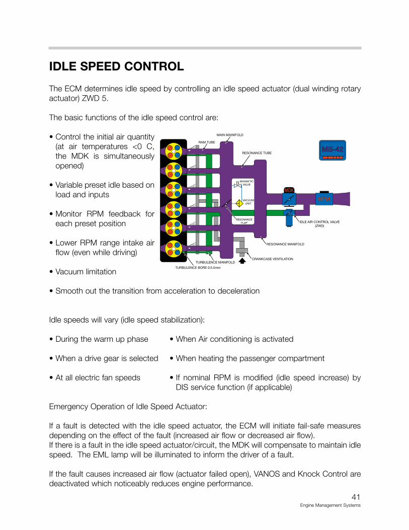
IDLE SPEED CONTROL
The ECM determines idle speed by controlling an idle speed actuator (dual winding rotaryactuator) ZWD 5.
The basic functions of the idle speed control are:
• Control the initial air quantity(at air temperatures <0 C,the MDK is simultaneouslyopened)
• Variable preset idle based onload and inputs
• Monitor RPM feedback foreach preset position
• Lower RPM range intake airflow (even while driving)
• Vacuum limitation
• Smooth out the transition from acceleration to deceleration
Idle speeds will vary (idle speed stabilization):
• During the warm up phase • When Air conditioning is activated
• When a drive gear is selected • When heating the passenger compartment
• At all electric fan speeds • If nominal RPM is modified (idle speed increase) byDIS service function (if applicable)
Emergency Operation of Idle Speed Actuator:
If a fault is detected with the idle speed actuator, the ECM will initiate fail-safe measuresdepending on the effect of the fault (increased air flow or decreased air flow).If there is a fault in the idle speed actuator/circuit, the MDK will compensate to maintain idlespeed. The EML lamp will be illuminated to inform the driver of a fault.
If the fault causes increased air flow (actuator failed open), VANOS and Knock Control aredeactivated which noticeably reduces engine performance.
41Engine Management Systems
MDK
HFM
MAGNETICVALVE
VACUUMUNIT
MS-42MS-42
RESONANCEFLAP
RAM TUBE
MAIN MAINIFOLD
RESONANCE TUBE
IDLE AIR CONTROL VALVE(ZWD)
RESONANCE MANIFOLD
CRANKCASE VENTILATIONTURBULENCE MANIFOLD
TURBULENCE BORE 0:5.5mm
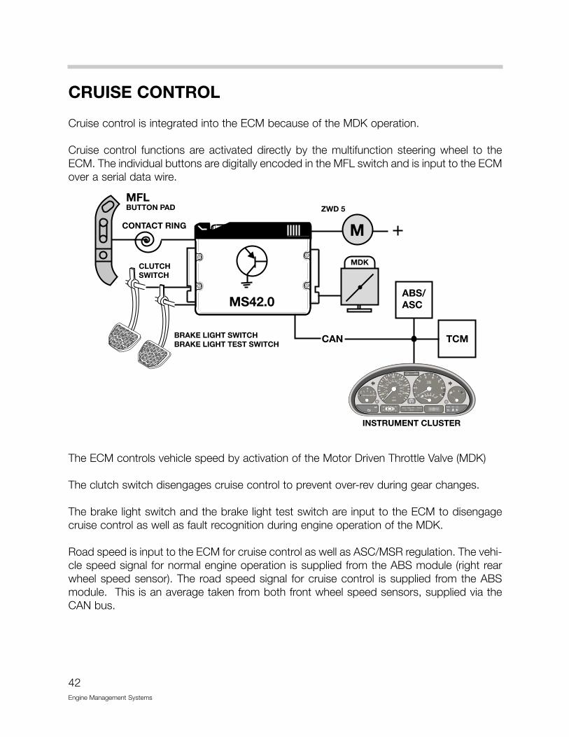
CRUISE CONTROL
Cruise control is integrated into the ECM because of the MDK operation.
Cruise control functions are activated directly by the multifunction steering wheel to theECM. The individual buttons are digitally encoded in the MFL switch and is input to the ECMover a serial data wire.
The ECM controls vehicle speed by activation of the Motor Driven Throttle Valve (MDK)
The clutch switch disengages cruise control to prevent over-rev during gear changes.
The brake light switch and the brake light test switch are input to the ECM to disengagecruise control as well as fault recognition during engine operation of the MDK.
Road speed is input to the ECM for cruise control as well as ASC/MSR regulation. The vehi-cle speed signal for normal engine operation is supplied from the ABS module (right rearwheel speed sensor). The road speed signal for cruise control is supplied from the ABSmodule. This is an average taken from both front wheel speed sensors, supplied via theCAN bus.
42Engine Management Systems
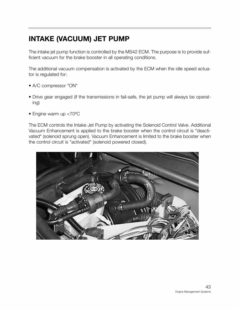
INTAKE (VACUUM) JET PUMP
The intake jet pump function is controlled by the MS42 ECM. The purpose is to provide suf-ficient vacuum for the brake booster in all operating conditions.
The additional vacuum compensation is activated by the ECM when the idle speed actua-tor is regulated for:
• A/C compressor "ON"
• Drive gear engaged (if the transmissions in fail-safe, the jet pump will always be operat-ing)
• Engine warm up <70ºC
The ECM controls the Intake Jet Pump by activating the Solenoid Control Valve. AdditionalVacuum Enhancement is applied to the brake booster when the control circuit is "deacti-vated" (solenoid sprung open). Vacuum Enhancement is limited to the brake booster whenthe control circuit is "activated" (solenoid powered closed).
43Engine Management Systems
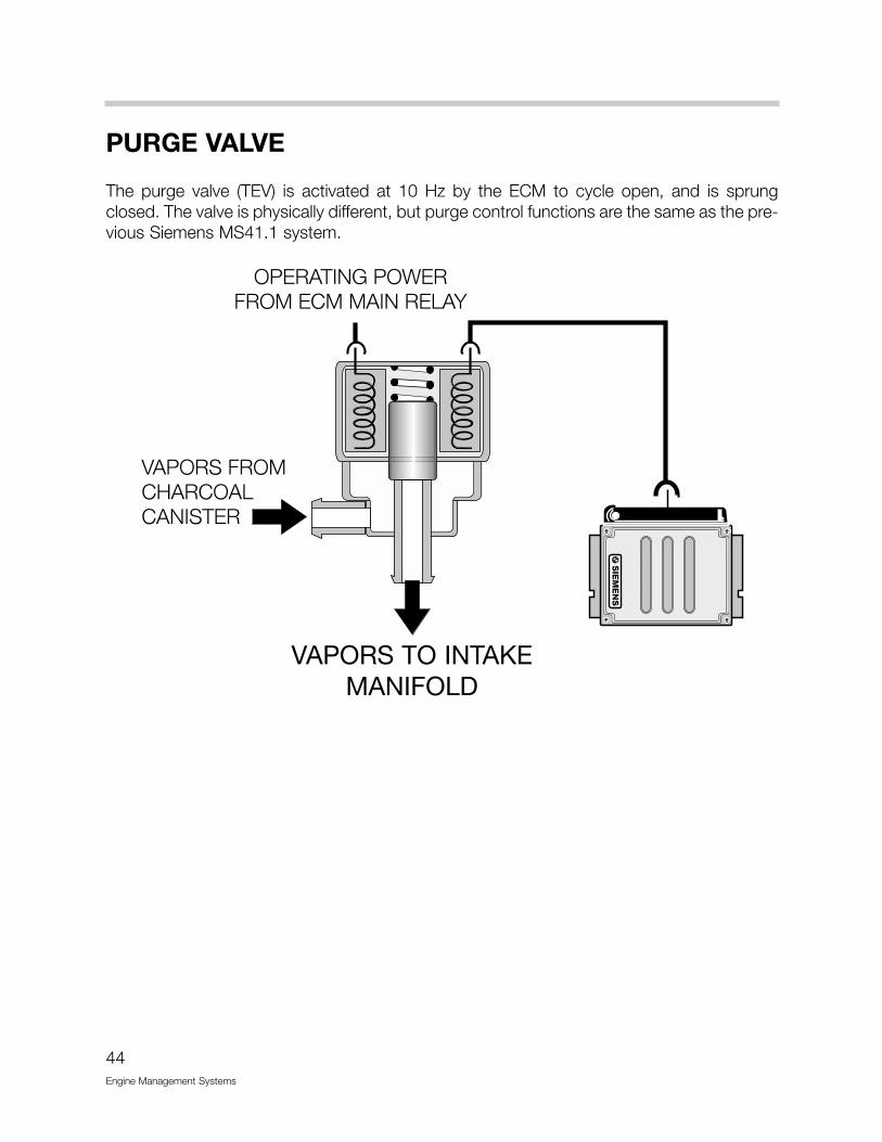
PURGE VALVE
The purge valve (TEV) is activated at 10 Hz by the ECM to cycle open, and is sprungclosed. The valve is physically different, but purge control functions are the same as the pre-vious Siemens MS41.1 system.
44Engine Management Systems
VAPORS TO INTAKEMANIFOLD
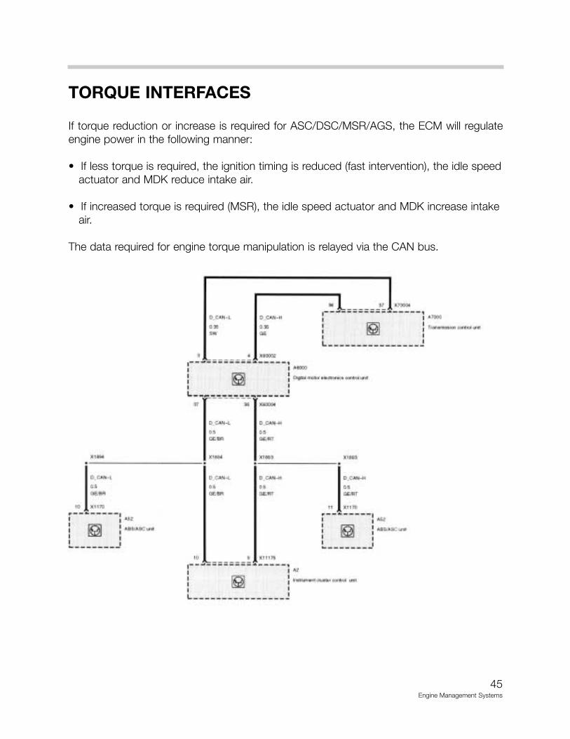
TORQUE INTERFACES
If torque reduction or increase is required for ASC/DSC/MSR/AGS, the ECM will regulateengine power in the following manner:
• If less torque is required, the ignition timing is reduced (fast intervention), the idle speedactuator and MDK reduce intake air.
• If increased torque is required (MSR), the idle speed actuator and MDK increase intake air.
The data required for engine torque manipulation is relayed via the CAN bus.
45Engine Management Systems

LEAKAGE DIAGNOSIS PUMP (LDP)
The location of the LDP and charcoal canister have changed. This combination assemblyis located under the right rear trunk floor.
EVAPORATIVE FUEL SYSTEM PRESSURE LEAK DIAGNOSIS MS42.0
The LDP is capable of detecting a leak as small as 0.5 mm.
The LDP is a unitized component that contains the following:
• Vacuum chamber• Pneumatic pump chamber• DME activated vacuum solenoid• Reed switch providing a switched voltage feedback signal to the DME
The LDP assembly is only replaceable as a complete unitized component, however, it isseparate from the charcoal canister.
* Location - under right rear trunk floor
46Engine Management Systems
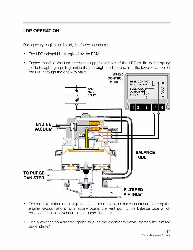
LDP OPERATION
During every engine cold start, the following occurs:
• The LDP solenoid is energized by the ECM
• Engine manifold vacuum enters the upper chamber of the LDP to lift up the springloaded diaphragm pulling ambient air through the filter and into the lower chamber ofthe LDP through the one way valve.
• The solenoid is then de-energized, spring pressure closes the vacuum port blocking theengine vacuum and simultaneously opens the vent port to the balance tube whichreleases the captive vacuum in the upper chamber.
• This allows the compressed spring to push the diaphragm down, starting the “limiteddown stroke”.
47Engine Management Systems
MS42.0CONTROL
MODULE
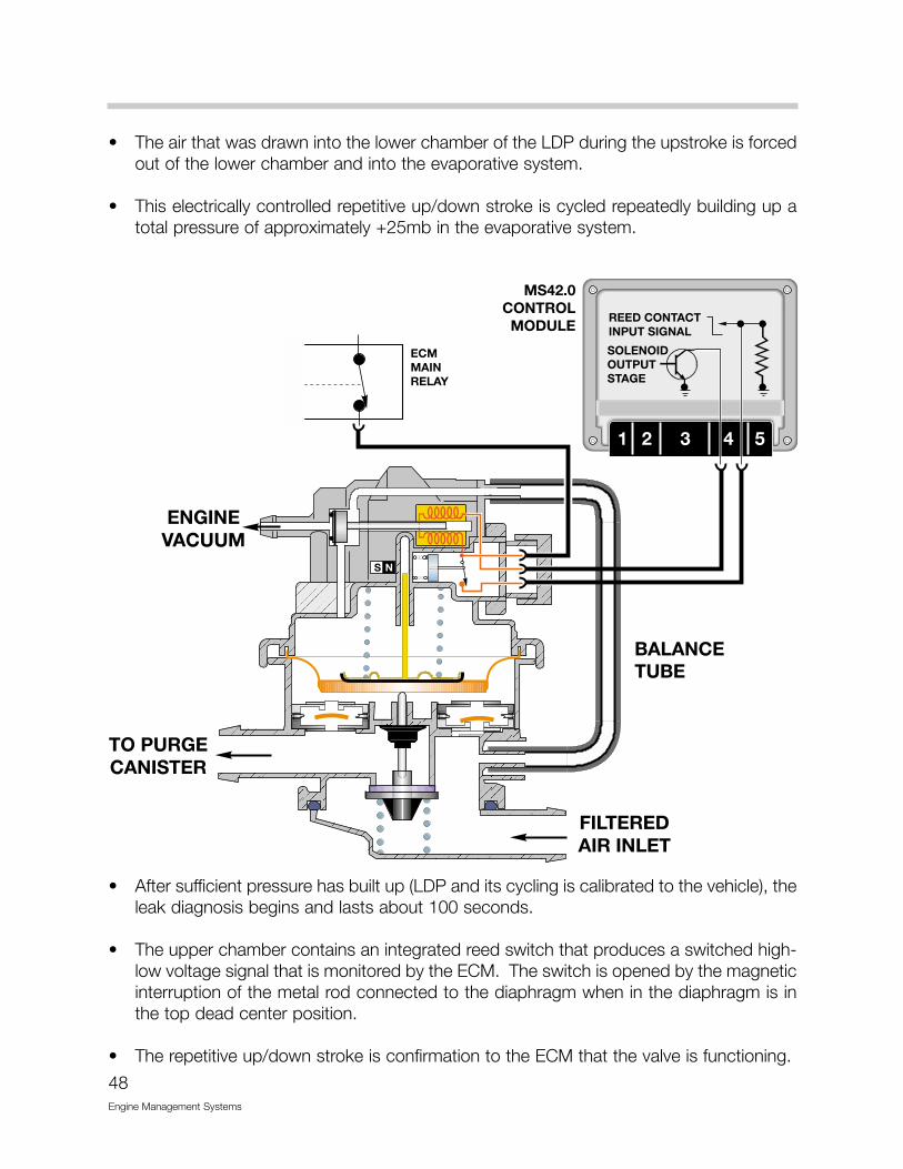
• The air that was drawn into the lower chamber of the LDP during the upstroke is forcedout of the lower chamber and into the evaporative system.
• This electrically controlled repetitive up/down stroke is cycled repeatedly building up atotal pressure of approximately +25mb in the evaporative system.
• After sufficient pressure has built up (LDP and its cycling is calibrated to the vehicle), theleak diagnosis begins and lasts about 100 seconds.
• The upper chamber contains an integrated reed switch that produces a switched high-low voltage signal that is monitored by the ECM. The switch is opened by the magneticinterruption of the metal rod connected to the diaphragm when in the diaphragm is inthe top dead center position.
• The repetitive up/down stroke is confirmation to the ECM that the valve is functioning.
48Engine Management Systems
MS42.0CONTROL
MODULE

The ECM also monitors the length of time it takes for the reed switch to open, which isopposed by pressure under the diaphragm in the lower chamber. The LDP is still cycled,but at a frequency that depends upon the rate of pressure loss in the lower chamber.
• If the pumping frequency is below parameters, there is no leak present.
• If the pumping frequency is above parameters, this indicates sufficient pressure can notbuild up in the lower chamber and evaporative system, indicating a leak.
A fault code can be recorded by each ECM indicating an evaporative system leak. Upontest completion, the ECM releases the ground path to the LDP and the internal spring push-es the diaphragm for the “full down stroke”.
At bottom dead center, the diaphragm rod opens the canister vent valve. This allows forfresh air intake from the filter for normal purge system operation.
The LDP is diagnosable with the DIS including a service function activation test.
49Engine Management Systems
MS42.0CONTROL
MODULE
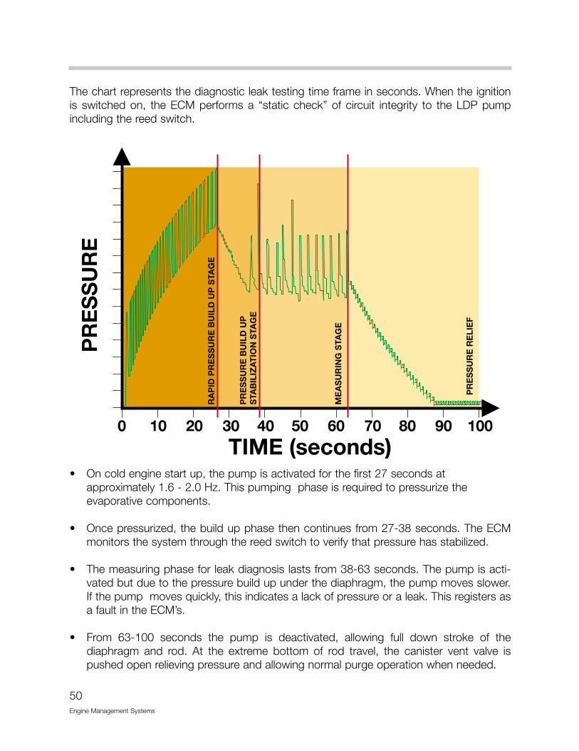
The chart represents the diagnostic leak testing time frame in seconds. When the ignitionis switched on, the ECM performs a “static check” of circuit integrity to the LDP pumpincluding the reed switch.
• On cold engine start up, the pump is activated for the first 27 seconds at approximately 1.6 - 2.0 Hz. This pumping phase is required to pressurize the evaporative components.
• Once pressurized, the build up phase then continues from 27-38 seconds. The ECMmonitors the system through the reed switch to verify that pressure has stabilized.
• The measuring phase for leak diagnosis lasts from 38-63 seconds. The pump is acti-vated but due to the pressure build up under the diaphragm, the pump moves slower.If the pump moves quickly, this indicates a lack of pressure or a leak. This registers asa fault in the ECM’s.
• From 63-100 seconds the pump is deactivated, allowing full down stroke of thediaphragm and rod. At the extreme bottom of rod travel, the canister vent valve ispushed open relieving pressure and allowing normal purge operation when needed.
50Engine Management Systems
51Engine Management Systems
MOTOR DRIVEN THROTTLE VALVE
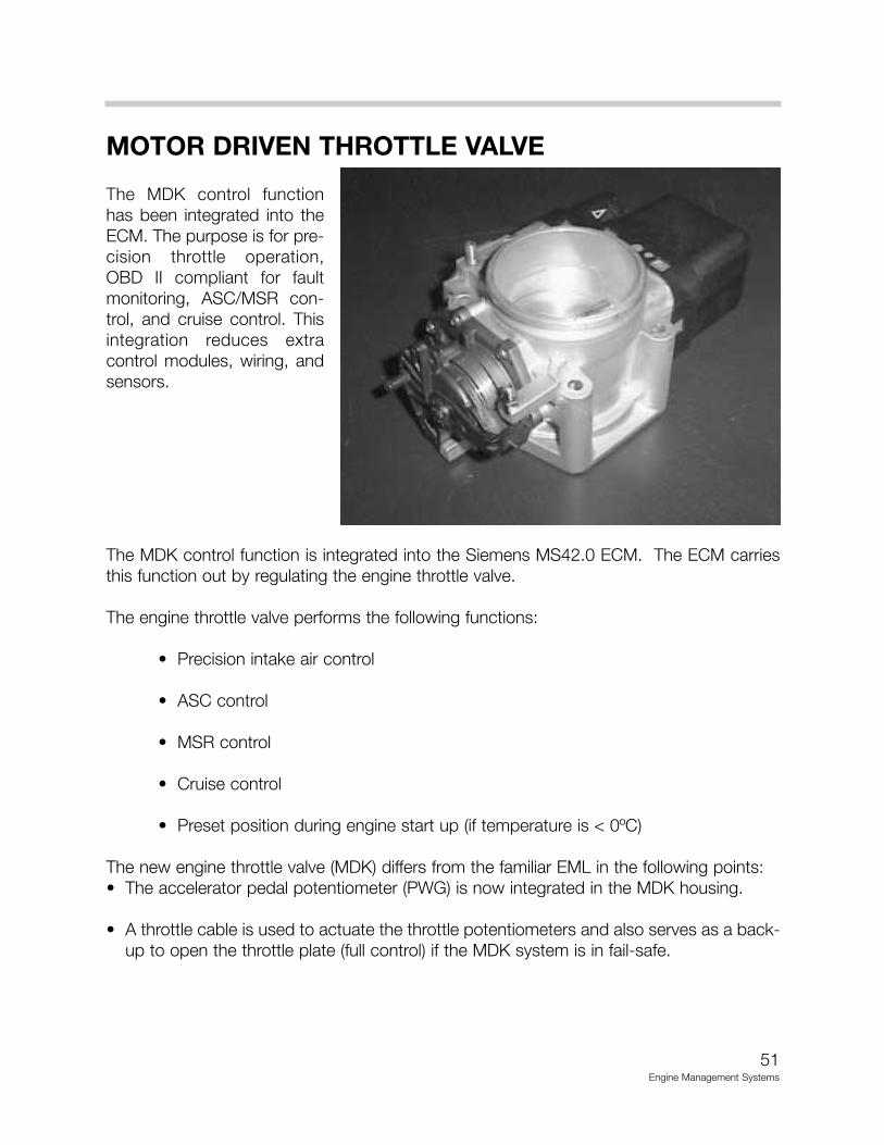
The MDK control functionhas been integrated into theECM. The purpose is for pre-cision throttle operation,OBD II compliant for faultmonitoring, ASC/MSR con-trol, and cruise control. Thisintegration reduces extracontrol modules, wiring, andsensors.
The MDK control function is integrated into the Siemens MS42.0 ECM. The ECM carriesthis function out by regulating the engine throttle valve.
The engine throttle valve performs the following functions:
• Precision intake air control
• ASC control
• MSR control
• Cruise control
• Preset position during engine start up (if temperature is < 0ºC)
The new engine throttle valve (MDK) differs from the familiar EML in the following points:• The accelerator pedal potentiometer (PWG) is now integrated in the MDK housing.
• A throttle cable is used to actuate the throttle potentiometers and also serves as a back-up to open the throttle plate (full control) if the MDK system is in fail-safe.
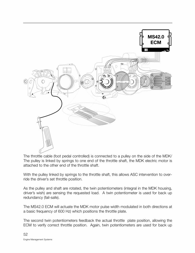
The throttle cable (foot pedal controlled) is connected to a pulley on the side of the MDK/The pulley is linked by springs to one end of the throttle shaft, the MDK electric motor isattached to the other end of the throttle shaft.
With the pulley linked by springs to the throttle shaft, this allows ASC intervention to over-ride the driver’s set throttle position.
As the pulley and shaft are rotated, the twin potentiometers (integral in the MDK housing,driver’s wish) are sensing the requested load. A twin potentiometer is used for back upredundancy (fail-safe).
The MS42.0 ECM will actuate the MDK motor pulse width modulated in both directions ata basic frequency of 600 Hz) which positions the throttle plate.
The second twin potentiometers feedback the actual throttle plate position, allowing theECM to verify correct throttle position. Again, twin potentiometers are used for back up
52Engine Management Systems
MDK EMERGENCY OPERATION
If a fault is detected in the system, the following modes of operation are:
• Emergency operation 1 - Faults which do not impair safety, but which adversely affectthe functioning of the MDK.
• Emergency operation 2 - Applies when faults are encountered which might impair safe driving operation.
• Emergency operation of idle speed actuator.
EMERGENCY OPERATION 1
• Activation of the EML warning lamp.
• MDK is deactivated, the throttle valve is opened mechanically by the springs and throt-tle cable.
• To maintain vehicle control, the MDK opening is compensated for by closing the idlespeed actuator and retarding the ignition (engine power reduction).
• Engine power is further limited by fuel injector cutout.
Emergency operation 1 limits the dynamic operation if one or more of the potentiometersfail. The engine can slowly reach maximum speed with limited power. The EML light willbe illuminated to alert the driver of a fault.
EMERGENCY OPERATION 2
If another fault is encountered in addition to emergency operation 1 or if the plausibility isaffected, emergency operation 2 is activated by the ECM.
An example of plausibility fault would be that the pulley position does not match the MDKposition and the associated airflow.
Emergency operation 2 can also be initiated by simultaneously pressing both the acceler-ator pedal and the brake pedal, or if a fault is encountered in the brake light switch diag-nosis.
53Engine Management Systems

When in emergency 2 operation mode, there is an engine speed limitation (slightly aboveidle speed) in addition to the measures for emergency operation 1.
In emergency operation 2, the engine speed is always limited to 1300 RPM if the brake isnot applied, and approximately 1000 RPM if the brake is applied.
The vehicle speed is limited to approximately 20-25 mph. The reason for limiting the vehi-cle speed is if the MDK is wide open, the vacuum assist is insufficient for the brakes.
The emergency operation functions are inactive when:
• Ignition is switched off, main relay is deactivated, and engine is started again
• A fault is not detected
• Brake pedal is not depressed
• The throttle valve is in the idle speed setting
FURTHER SAFETY CONCEPTS
The MDK safety concept can detect a jammed or binding throttle valve as well as a bro-ken link spring. This fault is detected by the ECM monitoring the feedback potentiometersfrom the MDK in relation to the pulse width modulation to activate the MDK motor.
Emergency operation functions if the throttle valve is jammed:
• Engine speed limitation depending on driver’s wish potentiometers and the MDK posi-tion.
• Limited vehicle speed if MDK is wide open.
• The ECM will alternate between 0 - 100% sensing ratio to “shake” the MDK loose.
In the event of a fault, the DIS or MODIC must be used to interrogate the fault memory, andclear the fault once the proper repair has been performed.
54Engine Management Systems
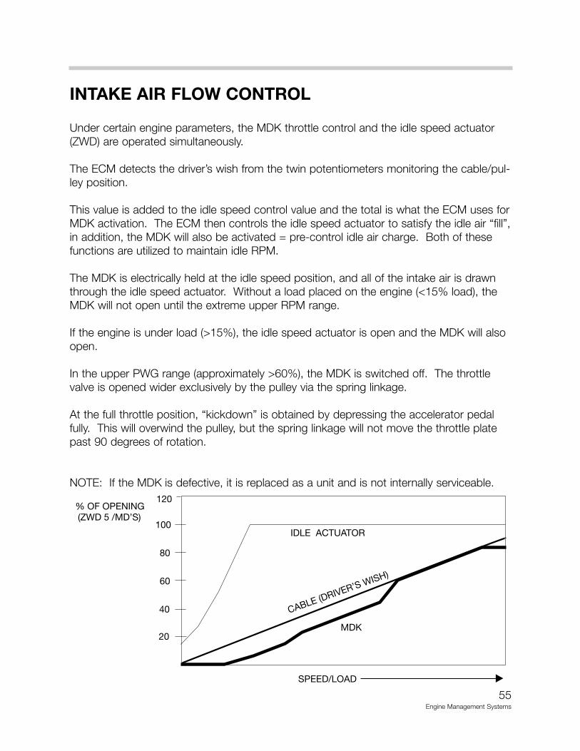
INTAKE AIR FLOW CONTROL
Under certain engine parameters, the MDK throttle control and the idle speed actuator(ZWD) are operated simultaneously.
The ECM detects the driver’s wish from the twin potentiometers monitoring the cable/pul-ley position.
This value is added to the idle speed control value and the total is what the ECM uses forMDK activation. The ECM then controls the idle speed actuator to satisfy the idle air “fill”,in addition, the MDK will also be activated = pre-control idle air charge. Both of thesefunctions are utilized to maintain idle RPM.
The MDK is electrically held at the idle speed position, and all of the intake air is drawnthrough the idle speed actuator. Without a load placed on the engine (<15% load), theMDK will not open until the extreme upper RPM range.
If the engine is under load (>15%), the idle speed actuator is open and the MDK will alsoopen.
In the upper PWG range (approximately >60%), the MDK is switched off. The throttlevalve is opened wider exclusively by the pulley via the spring linkage.
At the full throttle position, “kickdown” is obtained by depressing the accelerator pedalfully. This will overwind the pulley, but the spring linkage will not move the throttle platepast 90 degrees of rotation.
NOTE: If the MDK is defective, it is replaced as a unit and is not internally serviceable.
55Engine Management Systems
56Engine M
anagement S
ystems
MDK
HFMHFM
MAGNETICVALVE
VACUUMUNIT
MS42.0MS42.0RAM TUBE
MAIN MAINIFOLD
RESONANCE TUBE
IDLE AIR CONTROL VALVE(ZWD)
RESONANCE MANIFOLD
TURBULENCE MANIFOLD
TURBULENCE BORE 0:5.5mm