Embed Size (px)
Citation preview
Initial Print Date:08/02 Revision Date:09/02
Subject Page
Information/Communication . . . . . . . . . . . . . . . . . . . . . . . . . . . . . . . . . .5Introduction . . . . . . . . . . . . . . . . . . . . . . . . . . . . . . . . . . . . . . . . . . . . .5Radio Systems . . . . . . . . . . . . . . . . . . . . . . . . . . . . . . . . . . . . . . . . . . .5Audio Systems . . . . . . . . . . . . . . . . . . . . . . . . . . . . . . . . . . . . . . . . . . .5Telephone Systems . . . . . . . . . . . . . . . . . . . . . . . . . . . . . . . . . . . . . . . .5Navigation Systems . . . . . . . . . . . . . . . . . . . . . . . . . . . . . . . . . . . . . . .5
Radio and CD changer . . . . . . . . . . . . . . . . . . . . . . . . . . . . . . . . . . . . . .6New Features of the System . . . . . . . . . . . . . . . . . . . . . . . . . . . . . . . . .6
Components . . . . . . . . . . . . . . . . . . . . . . . . . . . . . . . . . . . . . . . . . . . . . .7BMW Business radio-CD . . . . . . . . . . . . . . . . . . . . . . . . . . . . . . . . . . .7BMW central information display radio (CID radio) . . . . . . . . . . . . . . . .7Design of the central information display . . . . . . . . . . . . . . . . . . . . . . . .8CD changer . . . . . . . . . . . . . . . . . . . . . . . . . . . . . . . . . . . . . . . . . . . .10BMW aerial systems . . . . . . . . . . . . . . . . . . . . . . . . . . . . . . . . . . . . . .10Rod aerial . . . . . . . . . . . . . . . . . . . . . . . . . . . . . . . . . . . . . . . . . . . . . .10Aerial diversity . . . . . . . . . . . . . . . . . . . . . . . . . . . . . . . . . . . . . . . . . . .11Components . . . . . . . . . . . . . . . . . . . . . . . . . . . . . . . . . . . . . . . . . . .11Rod aerial . . . . . . . . . . . . . . . . . . . . . . . . . . . . . . . . . . . . . . . . . . . . . .11FM aerial in bumper . . . . . . . . . . . . . . . . . . . . . . . . . . . . . . . . . . . . . .11Aerial diversity . . . . . . . . . . . . . . . . . . . . . . . . . . . . . . . . . . . . . . . . . . .11Aerial amplifier . . . . . . . . . . . . . . . . . . . . . . . . . . . . . . . . . . . . . . . . . .12Service mode for Radios . . . . . . . . . . . . . . . . . . . . . . . . . . . . . . . . . .12Service Mode for Business-CD . . . . . . . . . . . . . . . . . . . . . . . . . . . . . .12Service Mode for Radios CID . . . . . . . . . . . . . . . . . . . . . . . . . . . . . . .13Notes for Service . . . . . . . . . . . . . . . . . . . . . . . . . . . . . . . . . . . . . . . .13Diagnosis . . . . . . . . . . . . . . . . . . . . . . . . . . . . . . . . . . . . . . . . . . . . . .14Coding . . . . . . . . . . . . . . . . . . . . . . . . . . . . . . . . . . . . . . . . . . . . . . . .14Car & key memory . . . . . . . . . . . . . . . . . . . . . . . . . . . . . . . . . . . . . . .14
Audio systems . . . . . . . . . . . . . . . . . . . . . . . . . . . . . . . . . . . . . . . . . . . .15New features . . . . . . . . . . . . . . . . . . . . . . . . . . . . . . . . . . . . . . . . . . .15System comparison - sound pressure . . . . . . . . . . . . . . . . . . . . . . . .15System comparison - linearity . . . . . . . . . . . . . . . . . . . . . . . . . . . . . . .16
Table of Contents
Communications
Subject Page
Advantages of the systems . . . . . . . . . . . . . . . . . . . . . . . . . . . . . . . . .16HiFi System . . . . . . . . . . . . . . . . . . . . . . . . . . . . . . . . . . . . . . . . . . . .16HiFi amplifier . . . . . . . . . . . . . . . . . . . . . . . . . . . . . . . . . . . . . . . . . . . .16Low-range speakers (woofers) . . . . . . . . . . . . . . . . . . . . . . . . . . . . . .17High-range speakers (tweeters) . . . . . . . . . . . . . . . . . . . . . . . . . . . . .18Mid-range speakers . . . . . . . . . . . . . . . . . . . . . . . . . . . . . . . . . . . . . .18Top-HiFi System . . . . . . . . . . . . . . . . . . . . . . . . . . . . . . . . . . . . . . . . .20Top-HiFi Amplifier . . . . . . . . . . . . . . . . . . . . . . . . . . . . . . . . . . . . . . . .20Front low-range speaker (woofer) . . . . . . . . . . . . . . . . . . . . . . . . . . . .20High-range speakers (tweeters) . . . . . . . . . . . . . . . . . . . . . . . . . . . . .20Mid-range speaker . . . . . . . . . . . . . . . . . . . . . . . . . . . . . . . . . . . . . . .21Carver woofers (low-range speakers), rear . . . . . . . . . . . . . . . . . . . . .21Carver Woofer Operating principle . . . . . . . . . . . . . . . . . . . . . . . . . . .21System Operation Top-HiFi . . . . . . . . . . . . . . . . . . . . . . . . . . . . . . . . .23Top-HiFi with radio Business-CD, or CID radio . . . . . . . . . . . . . . . . . .23
Principle of Operation . . . . . . . . . . . . . . . . . . . . . . . . . . . . . . . . . . . . . .23HiFi amplifier . . . . . . . . . . . . . . . . . . . . . . . . . . . . . . . . . . . . . . . . . . . .23Top-HiFi amplifier . . . . . . . . . . . . . . . . . . . . . . . . . . . . . . . . . . . . . . . .24Improved overall acoustic impression . . . . . . . . . . . . . . . . . . . . . . . . .24Loudness . . . . . . . . . . . . . . . . . . . . . . . . . . . . . . . . . . . . . . . . . . . . . .24Speed-dependent volume control . . . . . . . . . . . . . . . . . . . . . . . . . . . .24Vehicle-specific equalizing . . . . . . . . . . . . . . . . . . . . . . . . . . . . . . . . . .25Dynamic equalizing . . . . . . . . . . . . . . . . . . . . . . . . . . . . . . . . . . . . . . .25Dynamic compression . . . . . . . . . . . . . . . . . . . . . . . . . . . . . . . . . . . .25Internal Temperature Monitoring . . . . . . . . . . . . . . . . . . . . . . . . . . . . .25Deactivation of the Top-HiFi amplifier during a telephone call . . . . . . .25Notes for Service . . . . . . . . . . . . . . . . . . . . . . . . . . . . . . . . . . . . . . . .25Diagnosis . . . . . . . . . . . . . . . . . . . . . . . . . . . . . . . . . . . . . . . . . . . . . .25Coding . . . . . . . . . . . . . . . . . . . . . . . . . . . . . . . . . . . . . . . . . . . . . . . .25
Navigation . . . . . . . . . . . . . . . . . . . . . . . . . . . . . . . . . . . . . . . . . . . . . . .26New features . . . . . . . . . . . . . . . . . . . . . . . . . . . . . . . . . . . . . . . . . . .26Components of System . . . . . . . . . . . . . . . . . . . . . . . . . . . . . . . . . . .26Central information display . . . . . . . . . . . . . . . . . . . . . . . . . . . . . . . . .27CID control panel . . . . . . . . . . . . . . . . . . . . . . . . . . . . . . . . . . . . . . . .28Navigation computer DVD . . . . . . . . . . . . . . . . . . . . . . . . . . . . . . . . .28GPS Aerial . . . . . . . . . . . . . . . . . . . . . . . . . . . . . . . . . . . . . . . . . . . . .28Wheel speed sensor . . . . . . . . . . . . . . . . . . . . . . . . . . . . . . . . . . . . . .28Reverse light switch . . . . . . . . . . . . . . . . . . . . . . . . . . . . . . . . . . . . . .29
Table of Contents
Subject Page
Principle of Operation . . . . . . . . . . . . . . . . . . . . . . . . . . . . . . . . . . . . . .29More accurate calculation of arrival time . . . . . . . . . . . . . . . . . . . . . . .29Improved direction . . . . . . . . . . . . . . . . . . . . . . . . . . . . . . . . . . . . . . .30Improved map presentation on the CID . . . . . . . . . . . . . . . . . . . . . . .30New map presentations . . . . . . . . . . . . . . . . . . . . . . . . . . . . . . . . . . .30Digitized maps on DVD . . . . . . . . . . . . . . . . . . . . . . . . . . . . . . . . . . . .30Operation . . . . . . . . . . . . . . . . . . . . . . . . . . . . . . . . . . . . . . . . . . . . . .30Service Information . . . . . . . . . . . . . . . . . . . . . . . . . . . . . . . . . . . . . . .31Diagnosis . . . . . . . . . . . . . . . . . . . . . . . . . . . . . . . . . . . . . . . . . . . . . .32Coding . . . . . . . . . . . . . . . . . . . . . . . . . . . . . . . . . . . . . . . . . . . . . . . .32Car & key memory . . . . . . . . . . . . . . . . . . . . . . . . . . . . . . . . . . . . . . .32
Service Mode Menus . . . . . . . . . . . . . . . . . . . . . . . . . . . . . . . . . . . . . . .33
Explanations . . . . . . . . . . . . . . . . . . . . . . . . . . . . . . . . . . . . . . . . . . . . . .34
Review Questions . . . . . . . . . . . . . . . . . . . . . . . . . . . . . . . . . . . . . . . . .35
Table of Contents
4Communications
Model: E85
Production: Start of Production MY 2003
Objectives:
After completion of this module you should be able to:
• Relate the Radio Options available.
• Know the component locations and removal procedures.
• Understand the CID operation.
5Communications
Information/Communication
Introduction
The E85 has soared to be the new dynamic leader in the market segment of premium road-sters. Its breathtaking design and even sportier handling place it distinctly higher than theE36/7.
In keeping with its top-of-the-range status, the Z4 offers new features in the field of infor-mation and communication systems.
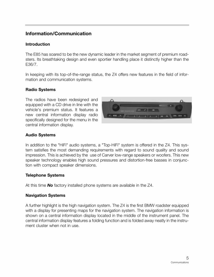
Radio Systems
The radios have been redesigned andequipped with a CD drive in line with thevehicle's premium status. It features anew central information display radiospecifically designed for the menu in thecentral information display.
Audio Systems
In addition to the "HiFi" audio systems, a "Top-HiFi" system is offered in the Z4. This sys-tem satisfies the most demanding requirements with regard to sound quality and soundimpression. This is achieved by the use of Carver low-range speakers or woofers. This newspeaker technology enables high sound pressures and distortion-free basses in conjunc-tion with compact speaker dimensions.
Telephone Systems
At this time No factory installed phone systems are available in the Z4.
Navigation Systems
A further highlight is the high navigation system. The Z4 is the first BMW roadster equippedwith a display for presenting maps for the navigation system. The navigation information isshown on a central information display located in the middle of the instrument panel. Thecentral information display features a folding function and is folded away neatly in the instru-ment cluster when not in use.
6Communications
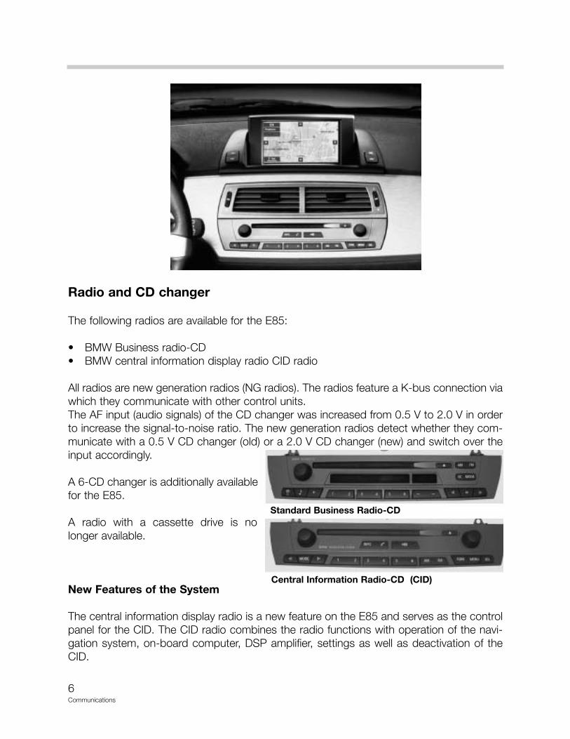
Radio and CD changer
The following radios are available for the E85:
• BMW Business radio-CD • BMW central information display radio CID radio
All radios are new generation radios (NG radios). The radios feature a K-bus connection viawhich they communicate with other control units.The AF input (audio signals) of the CD changer was increased from 0.5 V to 2.0 V in orderto increase the signal-to-noise ratio. The new generation radios detect whether they com-municate with a 0.5 V CD changer (old) or a 2.0 V CD changer (new) and switch over theinput accordingly.
A 6-CD changer is additionally availablefor the E85.
A radio with a cassette drive is nolonger available.
New Features of the System
The central information display radio is a new feature on the E85 and serves as the controlpanel for the CID. The CID radio combines the radio functions with operation of the navi-gation system, on-board computer, DSP amplifier, settings as well as deactivation of theCID.
Standard Business Radio-CD
Central Information Radio-CD (CID)
7Communications
Components
The radios can be optionally fitted at the factory in the following combinations:
• BMW Business Radio-CD• BMW Central Information Display Radio (CID Radio)
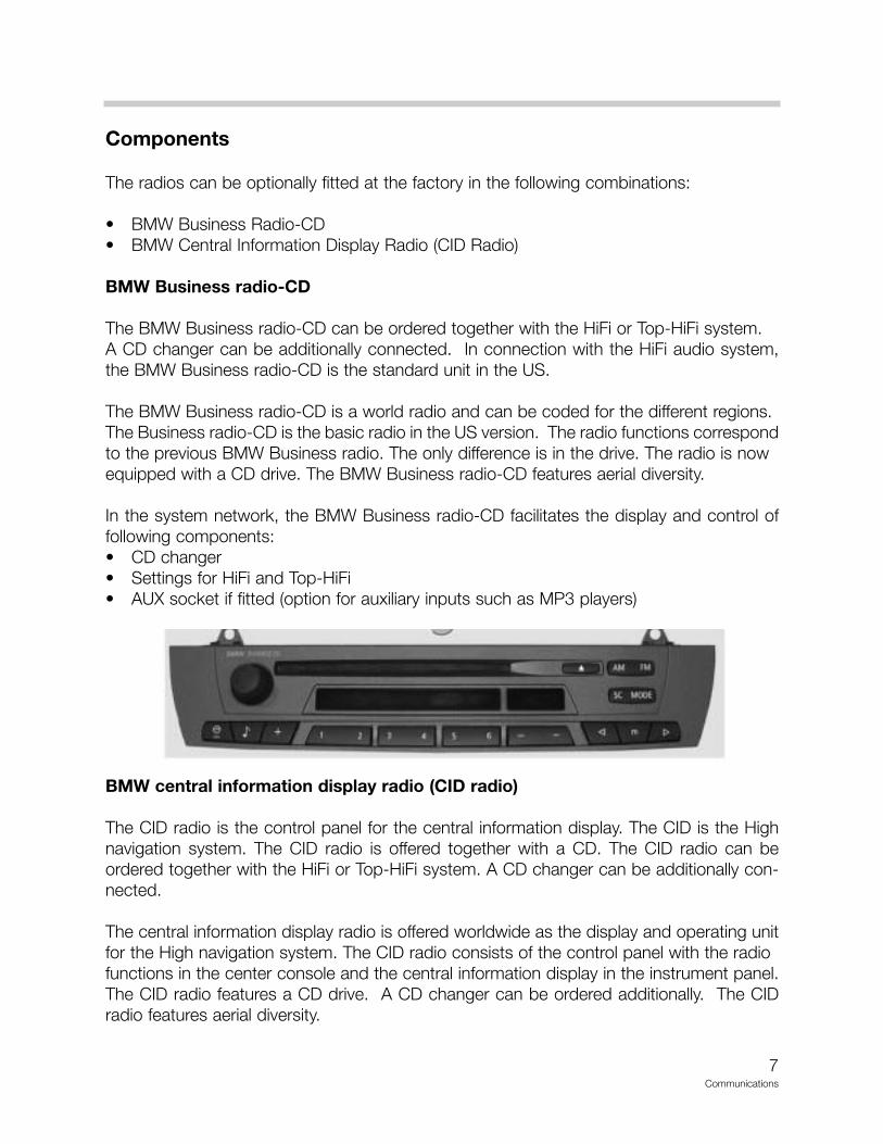
BMW Business radio-CD
The BMW Business radio-CD can be ordered together with the HiFi or Top-HiFi system. A CD changer can be additionally connected. In connection with the HiFi audio system,the BMW Business radio-CD is the standard unit in the US.
The BMW Business radio-CD is a world radio and can be coded for the different regions.The Business radio-CD is the basic radio in the US version. The radio functions correspondto the previous BMW Business radio. The only difference is in the drive. The radio is nowequipped with a CD drive. The BMW Business radio-CD features aerial diversity.
In the system network, the BMW Business radio-CD facilitates the display and control offollowing components:• CD changer• Settings for HiFi and Top-HiFi• AUX socket if fitted (option for auxiliary inputs such as MP3 players)
BMW central information display radio (CID radio)
The CID radio is the control panel for the central information display. The CID is the Highnavigation system. The CID radio is offered together with a CD. The CID radio can beordered together with the HiFi or Top-HiFi system. A CD changer can be additionally con-nected.
The central information display radio is offered worldwide as the display and operating unitfor the High navigation system. The CID radio consists of the control panel with the radiofunctions in the center console and the central information display in the instrument panel.The CID radio features a CD drive. A CD changer can be ordered additionally. The CIDradio features aerial diversity.
8Communications
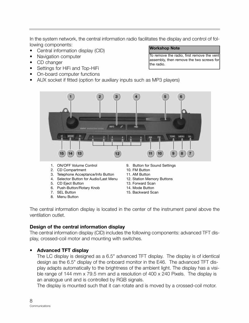
In the system network, the central information radio facilitates the display and control of fol-lowing components:• Central information display (CID)• Navigation computer• CD changer• Settings for HiFi and Top-HiFi• On-board computer functions• AUX socket if fitted (option for auxiliary inputs such as MP3 players)
The central information display is located in the center of the instrument panel above theventilation outlet.
Design of the central information displayThe central information display (CID) includes the following components: advanced TFT dis-play, crossed-coil motor and mounting with switches.
• Advanced TFT displayThe LC display is designed as a 6.5" advanced TFT display. The display is of identicaldesign as the 6.5" display of the onboard monitor in the E46. The advanced TFT dis-play adapts automatically to the brightness of the ambient light. The display has a visi-ble range of 144 mm x 79.5 mm and a resolution of 400 x 240 Pixels. The display is an analogue unit and is controlled by RGB signals.The display is mounted such that it can rotate and is moved by a crossed-coil motor.
1. ON/OFF Volume Control 9. Button for Sound Settings2. CD Compartment 10. FM Button3. Telephone Acceptance/Info Button 11. AM Button4. Selector Button for Audio/Last Menu 12. Station Memory Buttons5. CD Eject Button 13. Forward Scan6. Push-Button/Rotary Knob 14. Mode Button7. SEL Button 15. Backward Scan8. Menu Button
Workshop Note
To remove the radio, first remove the ventassembly, then remove the two screws forthe radio.
9Communications
• Crossed-coil motor with gear mechanism (Stepper Motor)The crossed-coil motor is a brushless DC motor. The positions of the display are detected by Hall sensors on the gear mechanism.
• MountingThe display and the crossed-coil motor are accommodated in a mounting. The mount-ing is located in the center of the instrument panel so that the same component can beused for left-hand drive and right-hand drive vehicles. The mounting is screwed flush with the surface of the instrument panel.
• SwitchLeft and right switches are integrated in the trough. The left switches serves the pur-pose of finely setting the display to improve the readability corresponding to the seat position and light conditions. The right switch serves to fold the display in and out.
When raised, the position is between 35-108 degrees. The position last stored (last func-tion memory position) is raised. The display can now be finely adjusted in steps (1 step =1.2 degrees) using the left-hand switch. The signal from the switch is sent directly to thestepper motor and is not transferred via the K-bus.
Manual fine adjustment of the display is also possible in a range from 35-108 degrees. Inan area below this range (< 35 degrees), the CID is closed automatically as it can no longerbe read effectively in this position. The right-hand switch can be used to close the display.
Navigation directions are not interrupted if the display is closed while the navigation systemis active. When terminal R is switched off, the CID is always closed and the last positionstored. The display can be switched off by means of a button in the main menu.
If the display is closed manually or electrically while driving, the display will remain closed atthe start of the next trip (last function memory position). The display must first be raisedagain by pressing the switch.
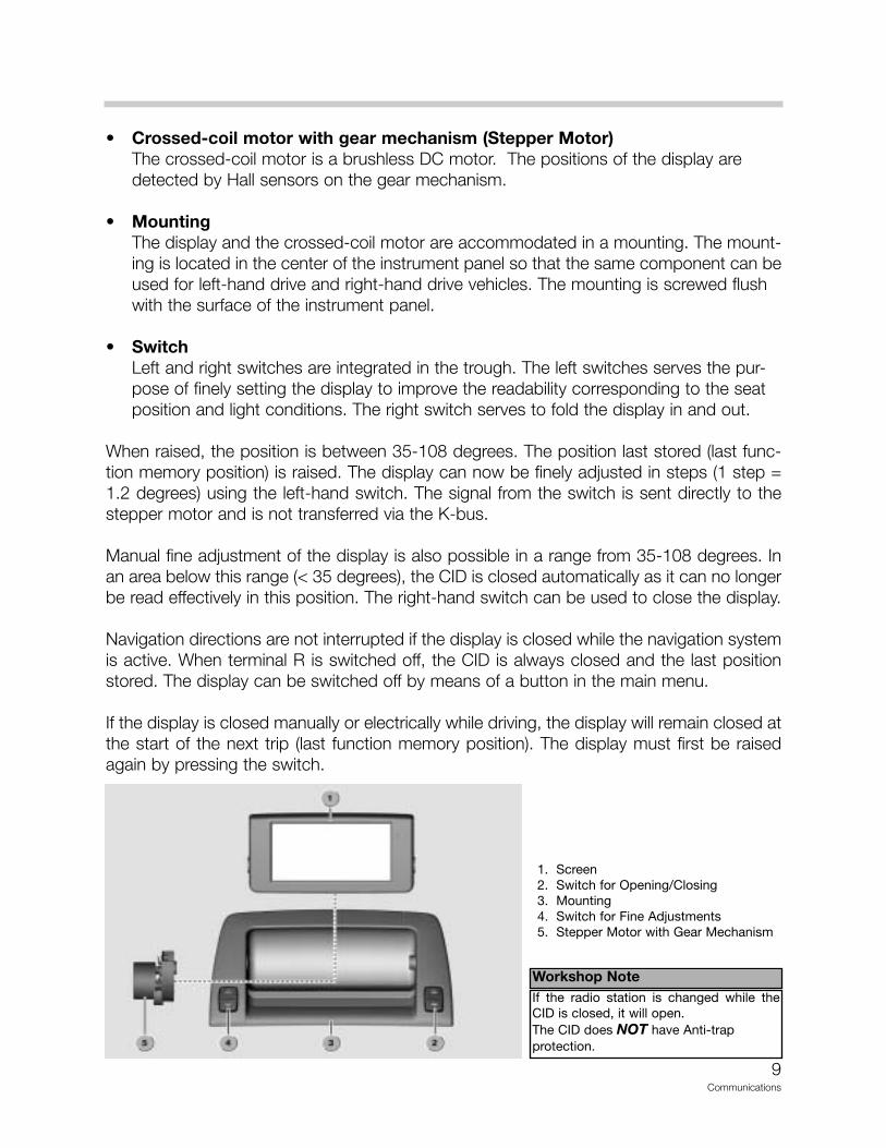
1. Screen2. Switch for Opening/Closing3. Mounting4. Switch for Fine Adjustments5. Stepper Motor with Gear Mechanism
Workshop NoteIf the radio station is changed while theCID is closed, it will open.The CID does NOT have Anti-trap protection.
10Communications
CD changer
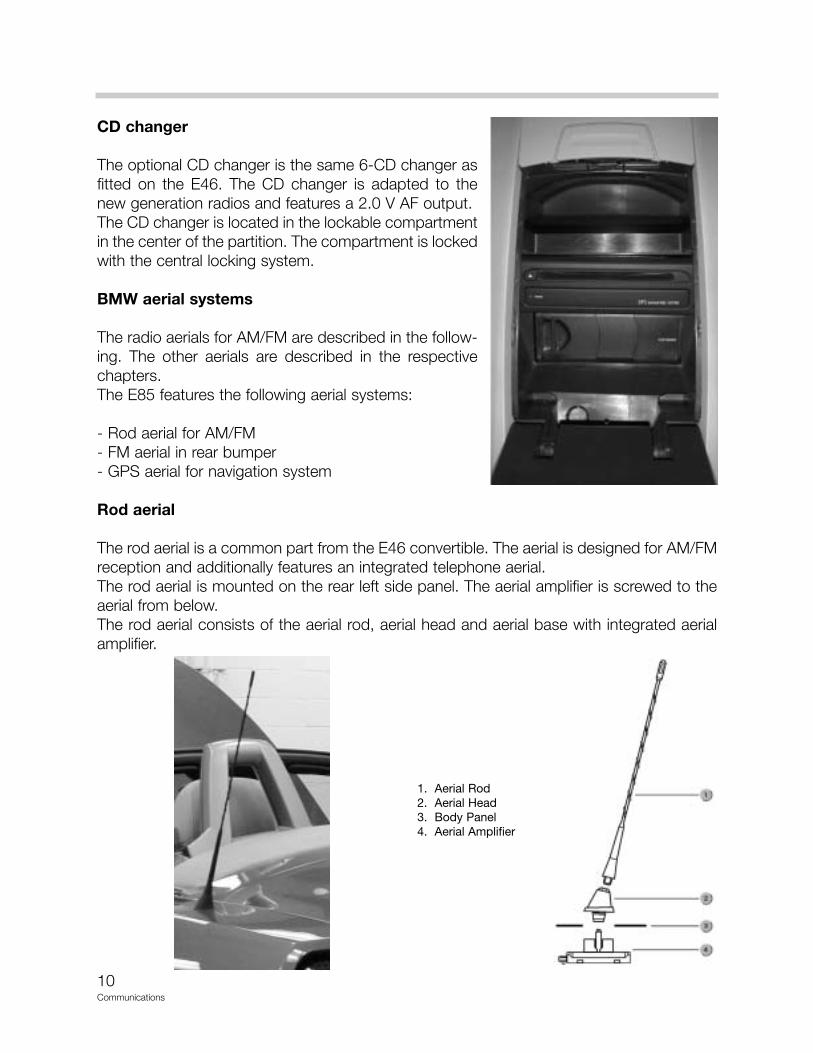
The optional CD changer is the same 6-CD changer asfitted on the E46. The CD changer is adapted to thenew generation radios and features a 2.0 V AF output.The CD changer is located in the lockable compartmentin the center of the partition. The compartment is lockedwith the central locking system.
BMW aerial systems
The radio aerials for AM/FM are described in the follow-ing. The other aerials are described in the respectivechapters.The E85 features the following aerial systems:
- Rod aerial for AM/FM- FM aerial in rear bumper- GPS aerial for navigation system
Rod aerial
The rod aerial is a common part from the E46 convertible. The aerial is designed for AM/FMreception and additionally features an integrated telephone aerial.The rod aerial is mounted on the rear left side panel. The aerial amplifier is screwed to theaerial from below.The rod aerial consists of the aerial rod, aerial head and aerial base with integrated aerialamplifier.
1. Aerial Rod2. Aerial Head3. Body Panel4. Aerial Amplifier
11Communications
Aerial diversity
The E85 features aerial diversity for the higher grade radios. Aerial diversity comprises fol-lowing components:- Rod aerial with amplifier- FM aerial in bumper- FM aerial amplifier- Aerial diversity
The aerial amplifier and aerial diversity are fitted in the rear left of the luggage compartment.The second FM aerial is located on the rear left in the bumper.
Components
The aerial diversity system includes the rod aerial with amplifier and the FM aerial in thebumper.
Rod aerialThe rod aerial is identical to that of the E46 convertible. The rod aerial is designed for thefollowing wavebands:
• AM 522 kHz - 1710 kHz• FM 87.5 MHz - 108 MHz
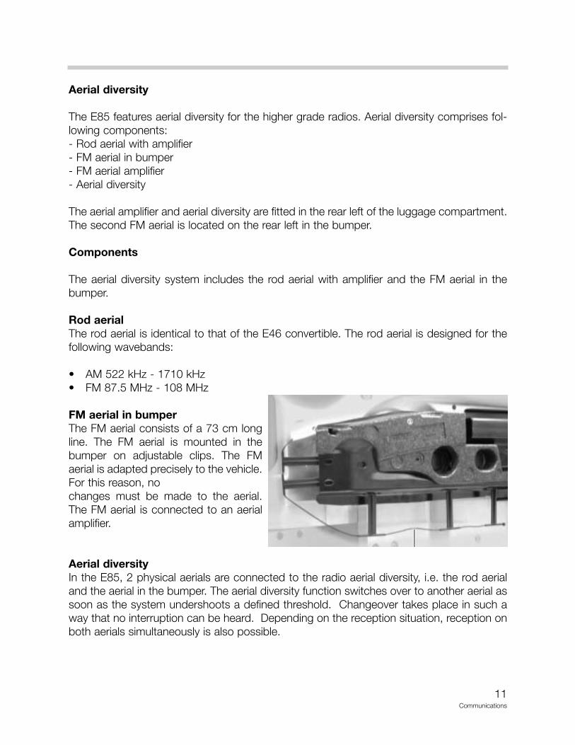
FM aerial in bumperThe FM aerial consists of a 73 cm longline. The FM aerial is mounted in thebumper on adjustable clips. The FMaerial is adapted precisely to the vehicle.For this reason, nochanges must be made to the aerial.The FM aerial is connected to an aerialamplifier.
Aerial diversityIn the E85, 2 physical aerials are connected to the radio aerial diversity, i.e. the rod aerialand the aerial in the bumper. The aerial diversity function switches over to another aerial assoon as the system undershoots a defined threshold. Changeover takes place in such away that no interruption can be heard. Depending on the reception situation, reception onboth aerials simultaneously is also possible.
12Communications
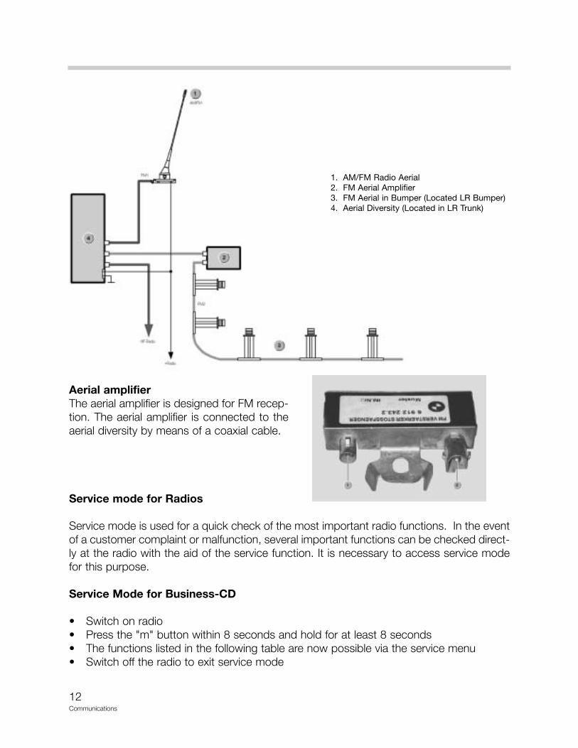
Aerial amplifierThe aerial amplifier is designed for FM recep-tion. The aerial amplifier is connected to theaerial diversity by means of a coaxial cable.
Service mode for Radios
Service mode is used for a quick check of the most important radio functions. In the eventof a customer complaint or malfunction, several important functions can be checked direct-ly at the radio with the aid of the service function. It is necessary to access service modefor this purpose.
Service Mode for Business-CD
• Switch on radio• Press the "m" button within 8 seconds and hold for at least 8 seconds• The functions listed in the following table are now possible via the service menu• Switch off the radio to exit service mode
1. AM/FM Radio Aerial2. FM Aerial Amplifier3. FM Aerial in Bumper (Located LR Bumper)4. Aerial Diversity (Located in LR Trunk)
13Communications
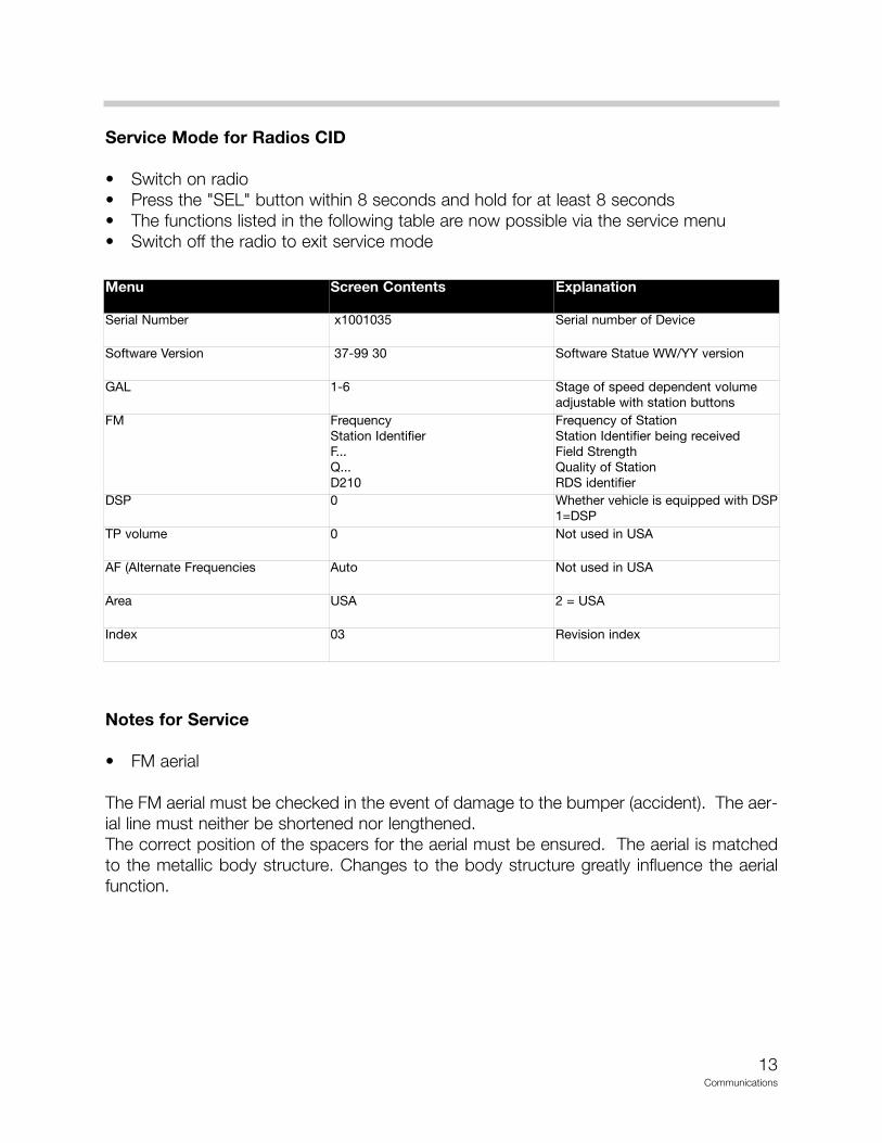
Service Mode for Radios CID
• Switch on radio• Press the "SEL" button within 8 seconds and hold for at least 8 seconds• The functions listed in the following table are now possible via the service menu• Switch off the radio to exit service mode
Notes for Service
• FM aerial
The FM aerial must be checked in the event of damage to the bumper (accident). The aer-ial line must neither be shortened nor lengthened. The correct position of the spacers for the aerial must be ensured. The aerial is matchedto the metallic body structure. Changes to the body structure greatly influence the aerialfunction.
Menu Screen Contents Explanation
Serial Number x1001035 Serial number of Device
Software Version 37-99 30 Software Statue WW/YY version
GAL 1-6 Stage of speed dependent volumeadjustable with station buttons
FM FrequencyStation IdentifierF...Q...D210
Frequency of StationStation Identifier being receivedField StrengthQuality of StationRDS identifier
DSP 0 Whether vehicle is equipped with DSP1=DSP
TP volume 0 Not used in USA
AF (Alternate Frequencies Auto Not used in USA
Area USA 2 = USA
Index 03 Revision index
14Communications
Diagnosis
Diagnosis of the radio without CID comprises the following:• Read identification• Read fault code memory• Delete fault code memory• Activate components, e.g. button functions, individual channels• Diagnosis query, e.g. field strength, setting of speed dependent volume control
Coding
Coding in the radio comprises the following functions:• New coding (country-specific functions)• Retrofitting• Conversion
Car & key memory
The following functions can be stored in the car & key memory:• Sound settings• Audio source• The last station is stored
Notes:
15Communications
Audio systems
The following audio systems are available for the E85:
• HiFi audio system• Top-HiFi audio system
New features
For the first time at BMW, binding audio standards have been defined for the E85 which willalso be adopted in successor models. In addition to the minimum requirements relating tothe systems, Carver speaker technology is used for the first time worldwide in a motor vehi-cle (Top-HiFi audio system). This system achieves substantial improvements in the low fre-quency range.
The audio standards stipulate the following requirements:• Classification in 2 audio systems: HiFi and Top-HiFi • Symmetry of sound field: All systems ensure uniform distribution of the sound field in the
vehicle and convey the overall acoustic impression that the source of the music is infront of the driver and passenger.
• Sound pressure• Linearity of stereo signal
With the aid of the Carver speaker technology, high sound pressures can be achievedalthough there is only a low resonance volume (space behind the speakers) available in theroadster.
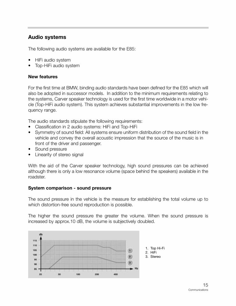
System comparison - sound pressure
The sound pressure in the vehicle is the measure for establishing the total volume up towhich distortion-free sound reproduction is possible.
The higher the sound pressure the greater the volume. When the sound pressure isincreased by approx.10 dB, the volume is subjectively doubled.
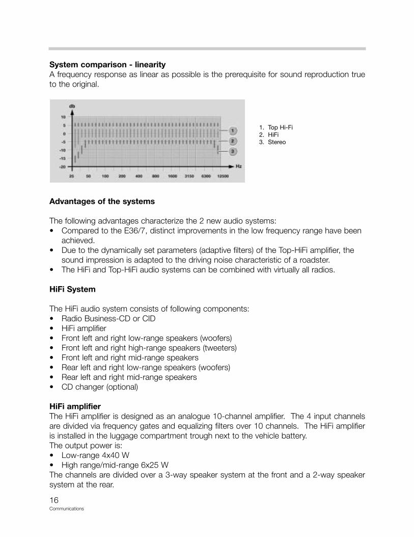
1. Top Hi-Fi2. HiFi3. Stereo
16Communications
System comparison - linearityA frequency response as linear as possible is the prerequisite for sound reproduction trueto the original.
Advantages of the systems
The following advantages characterize the 2 new audio systems:• Compared to the E36/7, distinct improvements in the low frequency range have been
achieved.• Due to the dynamically set parameters (adaptive filters) of the Top-HiFi amplifier, the
sound impression is adapted to the driving noise characteristic of a roadster.• The HiFi and Top-HiFi audio systems can be combined with virtually all radios.
HiFi System
The HiFi audio system consists of following components:• Radio Business-CD or CID• HiFi amplifier• Front left and right low-range speakers (woofers)• Front left and right high-range speakers (tweeters)• Front left and right mid-range speakers• Rear left and right low-range speakers (woofers)• Rear left and right mid-range speakers• CD changer (optional)
HiFi amplifierThe HiFi amplifier is designed as an analogue 10-channel amplifier. The 4 input channelsare divided via frequency gates and equalizing filters over 10 channels. The HiFi amplifieris installed in the luggage compartment trough next to the vehicle battery.The output power is:• Low-range 4x40 W• High range/mid-range 6x25 WThe channels are divided over a 3-way speaker system at the front and a 2-way speakersystem at the rear.
1. Top Hi-Fi2. HiFi3. Stereo
17Communications
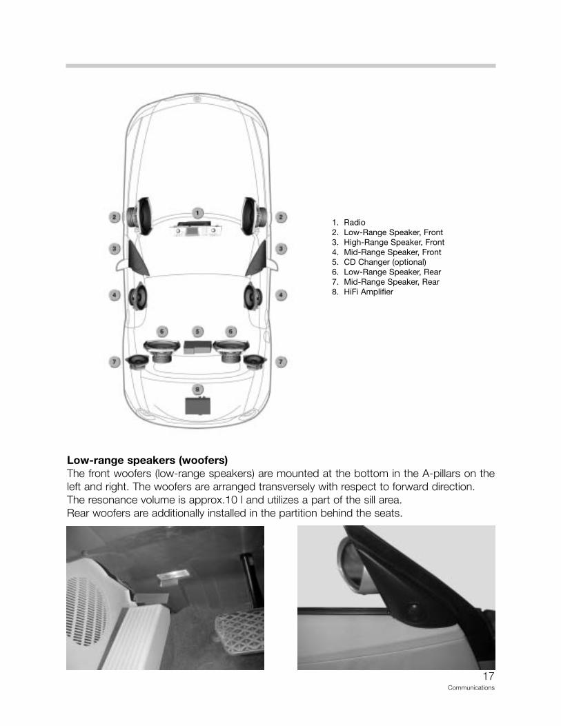
Low-range speakers (woofers)The front woofers (low-range speakers) are mounted at the bottom in the A-pillars on theleft and right. The woofers are arranged transversely with respect to forward direction.The resonance volume is approx.10 l and utilizes a part of the sill area.Rear woofers are additionally installed in the partition behind the seats.
1. Radio2. Low-Range Speaker, Front3. High-Range Speaker, Front4. Mid-Range Speaker, Front5. CD Changer (optional)6. Low-Range Speaker, Rear7. Mid-Range Speaker, Rear8. HiFi Amplifier
18Communications
High-range speakers (tweeters)The tweeter has a diameter of 26 mm and a fabric cap or calotte. The maximum loadcapacity is 25 W. The tweeter (high-range speaker) covers a frequency range from 4000 Hzto 20,000 Hz. The tweeter is connected to the woofer.The frequency range of the high-range speaker is set by means of a capacitor.
The tweeter (high-range speaker) is located in a panel mounted in the mirror triangle.The output direction of the tweeter is directed at the head area of the occupant opposite.The tweeter (high-range speaker) is based on a sealed design.
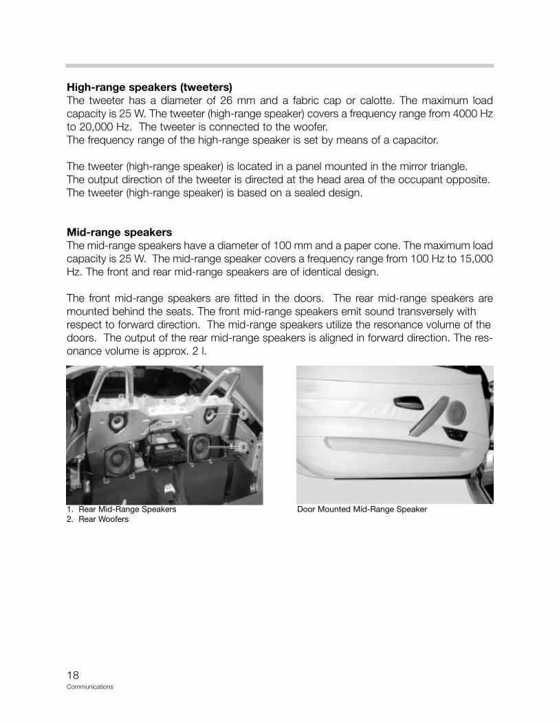
Mid-range speakersThe mid-range speakers have a diameter of 100 mm and a paper cone. The maximum loadcapacity is 25 W. The mid-range speaker covers a frequency range from 100 Hz to 15,000Hz. The front and rear mid-range speakers are of identical design.
The front mid-range speakers are fitted in the doors. The rear mid-range speakers aremounted behind the seats. The front mid-range speakers emit sound transversely withrespect to forward direction. The mid-range speakers utilize the resonance volume of thedoors. The output of the rear mid-range speakers is aligned in forward direction. The res-onance volume is approx. 2 l.
1. Rear Mid-Range Speakers2. Rear Woofers
Door Mounted Mid-Range Speaker
19Communications
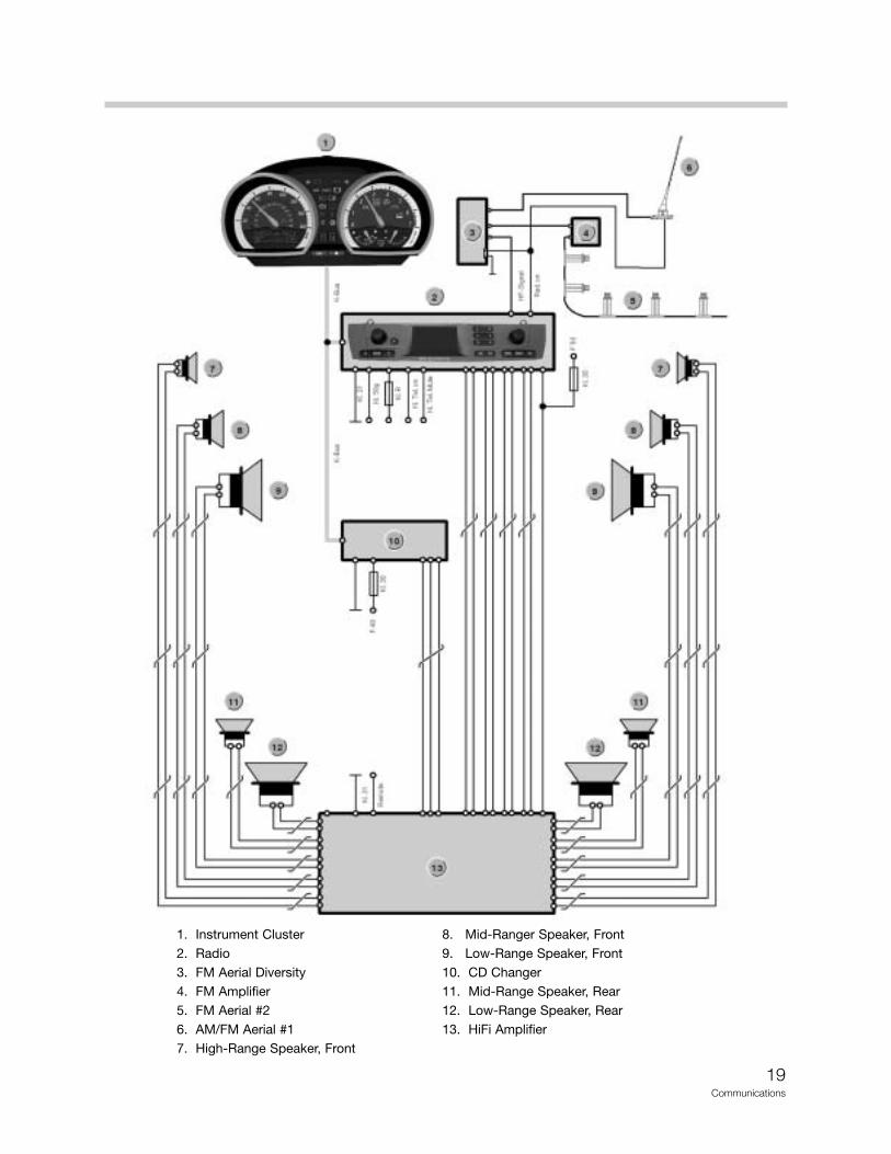
1. Instrument Cluster 8. Mid-Ranger Speaker, Front2. Radio 9. Low-Range Speaker, Front3. FM Aerial Diversity 10. CD Changer4. FM Amplifier 11. Mid-Range Speaker, Rear5. FM Aerial #2 12. Low-Range Speaker, Rear6. AM/FM Aerial #1 13. HiFi Amplifier7. High-Range Speaker, Front
20Communications
Top-HiFi System
The Top-HiFi audio system consists of following components:• Radio Business-CD or CID• Top-HiFi amplifier• Front left and right low-range speakers (woofers)• Front left and right high-range speakers (tweeters)• Front left and right mid-range speakers• Rear left and right mid-range speakers• Rear left and right low-range speakers (woofers) in Carver technology• CD changer (optional)
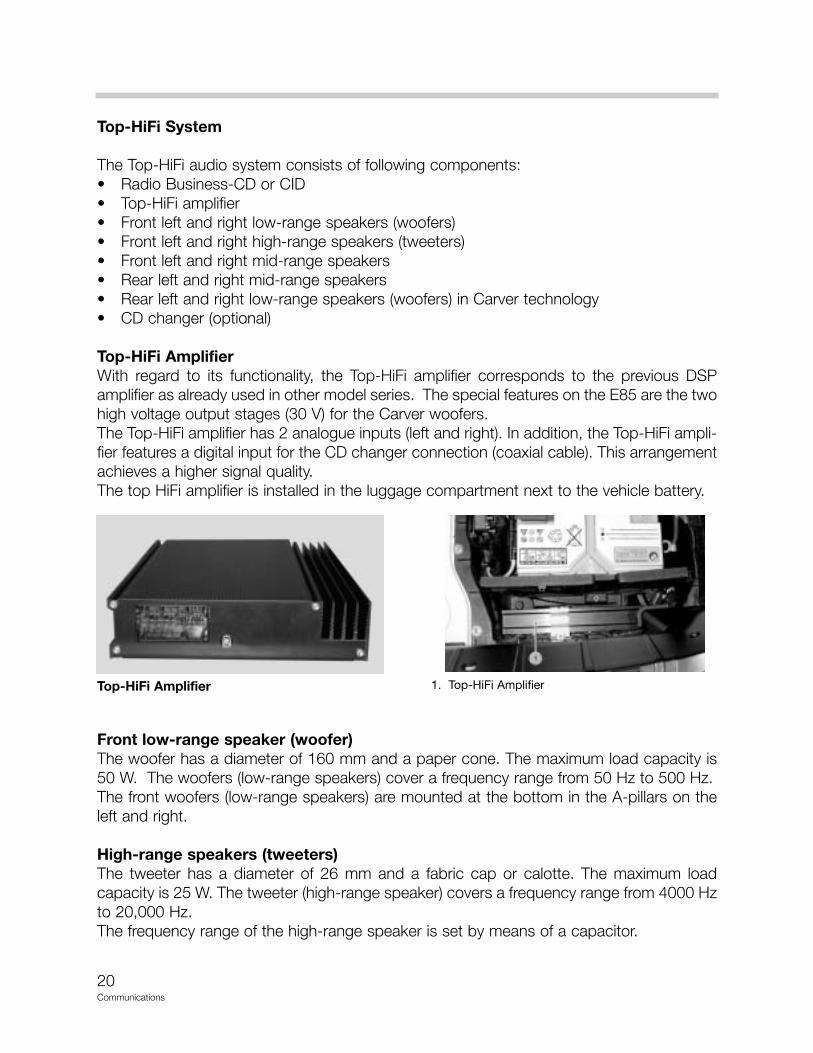
Top-HiFi AmplifierWith regard to its functionality, the Top-HiFi amplifier corresponds to the previous DSPamplifier as already used in other model series. The special features on the E85 are the twohigh voltage output stages (30 V) for the Carver woofers.The Top-HiFi amplifier has 2 analogue inputs (left and right). In addition, the Top-HiFi ampli-fier features a digital input for the CD changer connection (coaxial cable). This arrangementachieves a higher signal quality.The top HiFi amplifier is installed in the luggage compartment next to the vehicle battery.
Front low-range speaker (woofer)The woofer has a diameter of 160 mm and a paper cone. The maximum load capacity is50 W. The woofers (low-range speakers) cover a frequency range from 50 Hz to 500 Hz.The front woofers (low-range speakers) are mounted at the bottom in the A-pillars on theleft and right.
High-range speakers (tweeters)The tweeter has a diameter of 26 mm and a fabric cap or calotte. The maximum loadcapacity is 25 W. The tweeter (high-range speaker) covers a frequency range from 4000 Hzto 20,000 Hz. The frequency range of the high-range speaker is set by means of a capacitor.
Top-HiFi Amplifier 1. Top-HiFi Amplifier
21Communications
The tweeter (high-range speaker) is located in a panel mounted in the mirror triangle.The output direction of the tweeter is directed at the head area of the occupant opposite.The tweeter (high-range speaker) is based on a sealed design.
Mid-range speakerThe mid-range speaker has a diameter of 100 mm and an aluminum cone. The maximumload capacity is 50 W. The mid-range speaker covers a frequency range from 100 Hz to10,000 Hz. The front and rear mid-range speakers are identical.
The front mid-range speakers are fitted in the doors. The rear mid-range speakers areinstalled in the partition behind the seats.
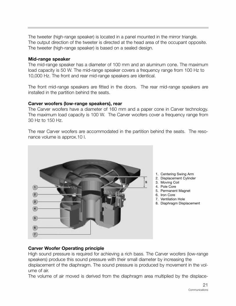
Carver woofers (low-range speakers), rearThe Carver woofers have a diameter of 160 mm and a paper cone in Carver technology.The maximum load capacity is 100 W. The Carver woofers cover a frequency range from30 Hz to 150 Hz.
The rear Carver woofers are accommodated in the partition behind the seats. The reso-nance volume is approx.10 l.
Carver Woofer Operating principleHigh sound pressure is required for achieving a rich bass. The Carver woofers (low-rangespeakers) produce this sound pressure with their small diameter by increasing thedisplacement of the diaphragm. The sound pressure is produced by movement in the vol-ume of air.The volume of air moved is derived from the diaphragm area multiplied by the displace-
1. Centering Swing Arm2. Displacement Cylinder3. Moving Coil4. Pole Core5. Permanent Magnet6. Iron Core7. Ventilation Hole8. Diaphragm Displacement
22Communications
ment. To date to achieve this, the largest possible diaphragm area (diameter of the speak-er) was used in conjunction with relatively low displacement (approx. 3-10 mm). A match-ing resonance volume is additionally required.In vehicle construction applications, this technology leads to a conflict between vehicledesign and vehicle equipment: Due to the design and comprehensive level of equipment,there is little package space available for large bass speakers.Carver technology represents a new approach in solving this problem. Thanks to Carvertechnology, a high sound pressure is produced with a small speaker diameter by increas-ing the diaphragm displacement (approx. 30 mm).
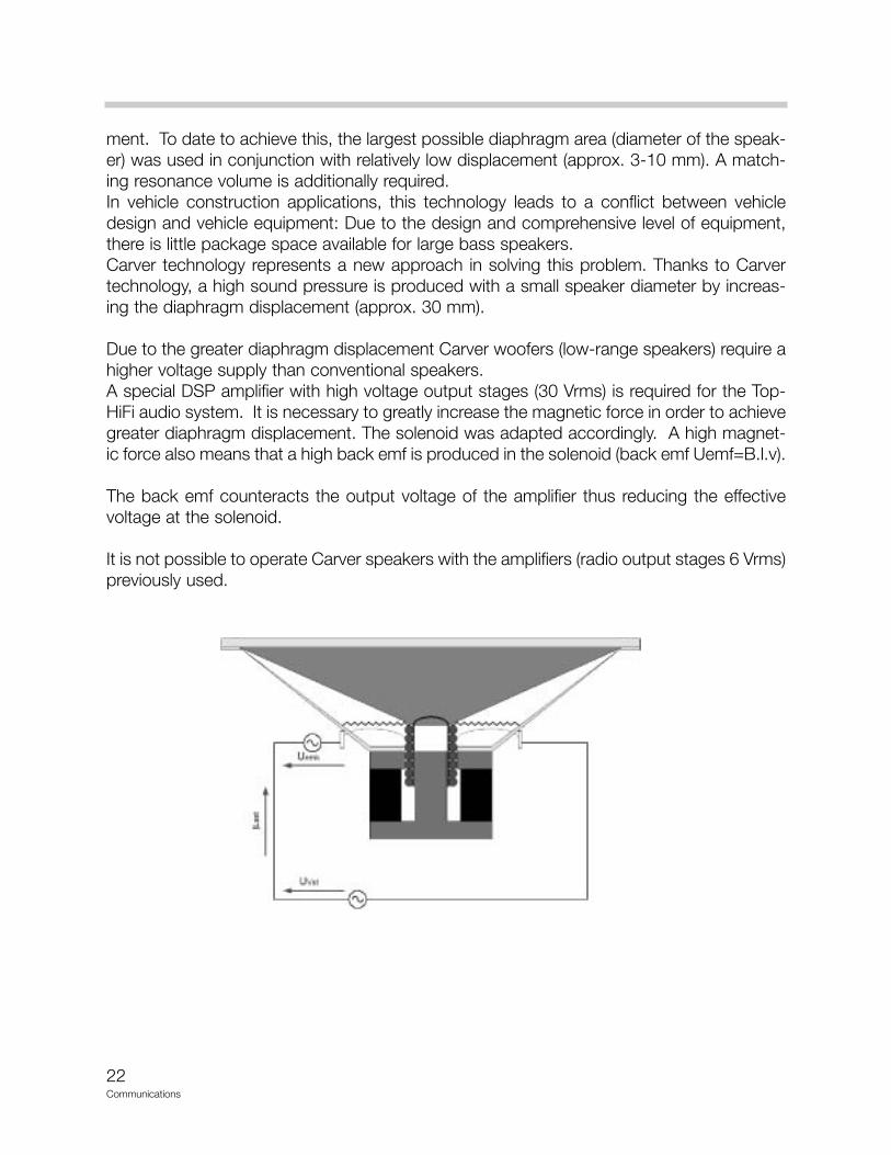
Due to the greater diaphragm displacement Carver woofers (low-range speakers) require ahigher voltage supply than conventional speakers.A special DSP amplifier with high voltage output stages (30 Vrms) is required for the Top-HiFi audio system. It is necessary to greatly increase the magnetic force in order to achievegreater diaphragm displacement. The solenoid was adapted accordingly. A high magnet-ic force also means that a high back emf is produced in the solenoid (back emf Uemf=B.l.v).
The back emf counteracts the output voltage of the amplifier thus reducing the effectivevoltage at the solenoid.
It is not possible to operate Carver speakers with the amplifiers (radio output stages 6 Vrms)previously used.
23Communications
System Operation Top-HiFi
The Top-HiFi audio system features a 10-channel analogue amplifier with DSP technologyas used in the current vehicles. The Top-HiFi amplifier is controlled with a constant audiosignal via the two analogue output channels of the radio. In addition, the Top-HiFi amplifierfeatures a digital input for the CD changer. The speakers are connected to the 10 outputchannels.
The Top-HiFi audio system has following output ratings:- Medium-range and high-range speakers: 6x20 W- Low-range speakers: 2x40 W- Carver low-range speakers: 2x100 W
Top-HiFi with radio Business-CD, or CID radioDepending on the type of radio installed, programmed sound settings can be selected orfreely programmed. In connection with the radio Business-CD, one of the following 3 pro-grammed sound settings can be selected in the "Tone"(sounds) menu:• Jazz• Hall• Cathedral
The radio CID radio with the central information display offers the following features:• 3 preset menus (see above)• 3 freely programmable menus
In the case of the CID radio, the overall acoustics can be set individually by means of a 7-band graphic equalizer.
Principle of Operation
All audio systems are controlled via the radio. The differences between the systems are inthe control of the amplifiers. The HiFi and Top-HiFi amplifiers do not feature direct controlfunctions.
HiFi amplifier
The HiFi amplifier is controlled via the radio.
The required settings are selected in the radio and output via 4 radio outputs to the ampli-fier. The amplifier amplifies the settings and distributes them over 10 channels.No variable matching takes place in the HiFi amplifier. Vehicle-specific equalizing is inte-grated in the HiFi amplifier.
24Communications
The following functions can be set in the radio:• Volume• Bass• Treble• Balance (left/right)• Fader (front/rear)• Loudness• Speed-dependent volume control
Top-HiFi amplifier
The Top-HiFi amplifier is also controlled via the radio. The Top-HiFi amplifier receives a con-stant audio signal for the left and right (via the two audio inputs) from the radio. The requiredsettings are transferred via the K-bus and formed in the amplifier.
The following functions can be set:• Volume• Bass• Treble• Balance (left/right)• Fader (front/rear)
In addition, the overall acoustics can be set individually (CID only) by means of a 7-bandgraphic equalizer.
Improved overall acoustic impressionWith the aid of software, adaptations were implemented in the Top-HiFi amplifier for the pur-pose of improving the overall acoustic impression. The following adaptations in the amplifier are conducted automatically:• Loudness• Speed-dependent volume control• Vehicle-specific equalizing• Dynamic equalizing• Dynamic compression• Internal temperature monitoring
LoudnessTo improve the listening nuance, the low frequencies are raised slightly at low volume set-tings.
Speed-dependent volume controlThe volume is raised as the driving speed increases. 6 characteristic curves are availablefor this purpose. The characteristics can be set individually in the service functions.
25Communications
Vehicle-specific equalizingThe acoustics are matched to the vehicle interior.
Dynamic equalizingThe acoustics are adapted to increasing driving noise.
Dynamic compressionThe dynamics must be compressed to avoid overloading the system. The upper level ofeffective dynamics is limited by the output power of the amplifier and the load capacity ofthe speakers. For this reason, the speed-dependent volume cannot be increased infinitely,
Internal Temperature MonitoringIn the event of excessively high temperature, the output of the output stages is reduced inorder to cool them.The temperature of the output stages is permanently monitored.
Notes for Service
DiagnosisNo diagnosis functions are provided for the audio systems.
CodingNo variant coding functions are provided for the audio systems.
Car & key memoryNo functions are available for the car & key memory.
26Communications
Navigation
New features
For the first time for a roadster, a High navigation system with map presentation on a dis-play has been developed for the E85.
The navigation system of the E85 is based on the familiar MK-3 navigation system. The nav-igation computer has been further developed and optimized for the E85 and is nowknown as navigation computer DVD.
The specific features of the new system include:• DVD drive• Faster processor• Larger memory
Advantages of New System• Map presentation for navigation in the Z4 roadster• The use of the DVD drive now facilitates presentation of all of the USA on one DVD • Extended destination entry functions• More accurate calculation of arrival time• Improved route planning• More exact traffic control management• New display presentation• Data on CD or DVD
Components of System
The High navigation system consists of following components:• Central information display CID• CID control panel• Navigation computer DVD• GPS aerial• Wheel speed sensor• Reversing light switch• Video module
27Communications
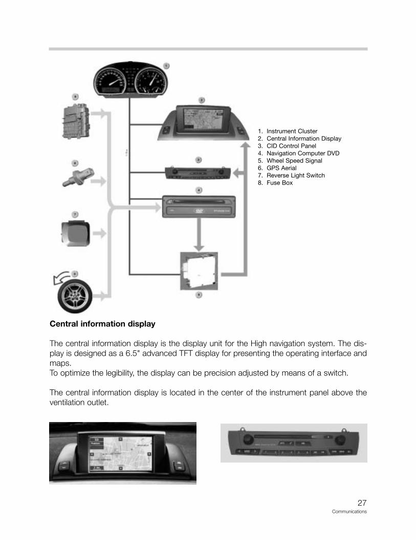
Central information display
The central information display is the display unit for the High navigation system. The dis-play is designed as a 6.5" advanced TFT display for presenting the operating interface andmaps.To optimize the legibility, the display can be precision adjusted by means of a switch.
The central information display is located in the center of the instrument panel above theventilation outlet.
1. Instrument Cluster2. Central Information Display3. CID Control Panel4. Navigation Computer DVD5. Wheel Speed Signal6. GPS Aerial7. Reverse Light Switch8. Fuse Box
28Communications
CID control panel
The central information display is located in the center of the instrument panel below theventilation outlet. The functions presented in the CID can be controlled with the rotary push-button on theright and the menu key on the CID control panel.
Navigation computer DVD
The navigation computer is located in the lockable compartment between the seats in thepartition between the vehicle interior and luggage compartment.
The navigation computer DVD incorporates the main functions for the navigation system.and contains the following components:• DVD drive for reading information of the digitized road maps on DVD or CD• GPS receiver for determining position before start of journey• Yaw rate sensor for calculating position while driving• Powerful processor for fast calculation of data• Memory modules for buffering data• Interfaces for communication with other systems and evaluating sensor data • Interfaces for outputting image data and voice information• GPS aerial
GPS Aerial
The GPS aerial receives the signals from GPS satellites and transfers the data (degrees lon-gitude, degrees latitude, Greenwich meantime (GMT)) to the GPS receiver in the navigationcomputer DVD for the purpose of calculating the position. This is of particular importanceduring initial or re-initialization of the system. These data are also read in during the restartprocedure. The GPS aerial is located in the middle of the roof frame behind the interior lamp.
Wheel speed sensor
The wheel speed sensor determines the rotary motion of the wheel. The information is rout-ed to the ABS/DSC control unit and the corresponding distance calculated. The condi-tioned signal is then made available to the navigation computer. The ABS sensor at the rearleft is used for the purpose of determining the speed signal.
29Communications
Reverse light switchWith the aid of the reverse light switch, the navigation system detects whether reverse gearis engaged. On manual transmission vehicles, the reverse light switch is located in themanual gearbox. On automatic vehicles, the reverse signal comes from the selector leverswitch.
Principle of Operation
The navigation computer DVD represents a further-development of the MK-3 computer.The computing capacity of the navigation computer DVD has been doubled (from previ-ously 54 MHz to 108 MHz). Likewise, the capacity of the memory modules has beenenlarged and a new flash module integrated to allow for considerably faster flashing (frompreviously 15.6 MIPS to 70.0 MIPS, million instructions per second).
The previous functions of the MK-3 computer have been fully adopted. Only the new ormodified functions are outlined in the following section.
The following functions are new:• Additional destination inputs• More accurate calculation of arrival time• Improved direction• Improved map presentation on the CID• New map presentations• Digitized road maps on DVD
The following new destination inputs are possible:• Direct input of border crossing points• Address book extended to 100 entries (20)• Storage of last 20 destinations (10)
More accurate calculation of arrival timeAbstract: By including traffic information (TMC), e.g. in the event of a traffic queue ahead,an alternative route is calculated and displayed.The expected time of arrival is calculated more accurately by including the average vehiclespeed corresponding to the type of road.For this purpose, the average speed of the last 7 minutes is stored corresponding to thetype of road (motorway, major trunk road, district road). Based on the selected route, thecomputer calculates the share of different types of road and the determined average speedso it can calculate the arrival time more accurately.
30Communications
Improved directionWhen changing from one motorway to another, the number ofthe new motorway is announced (voice information).
Improved map presentation on the CIDIn future, the maps will be presented in up to 256 colors. The indicator for the current posi-tion has been enlarged.
New map presentationsThe scaling of the maps has been extended to 1000 miles. The scales 200 miles, 500 milesand 1000 miles have been additionally introduced. As a result, all the USA can be shownon the display. The selected route is highlighted in white.
In addition, 3 maps can be shown in different scales.
The following scales can be presented:- The scale bar on the display corresponds to 1000 miles- The scale bar on the display corresponds to 500 miles- The scale bar on the display corresponds to 200 miles
The 200 miles, 500 miles and 1000 miles scales can only be presented in connection withDVD maps. The previous CD maps only provide scales of up to 100 miles.
The map scales are selected in the "Settings" menu under "Announcement."
Digitized maps on DVDThe navigation computer DVD is equipped with a DVD drive. The navigation computer DVDis retro-compatible and can be used in all MK-x systems. It can also read the previouslyused CDs.
OperationThe High navigation system is controlled by selecting the "GPS navigation" menu in themain menu of the central information display.
Basic settings are possible under the menu item “Settings” in the main menu to adapt thedisplay to country specific requirements. The various settings can be carried out in the win-dows. The red markings correspond to the current settings.
With the “Screen” menu item in the Settings menu it is possible to switch between full andsplit screen.
As a result, it is possible to show the map and the navigation arrow simultaneously.
Navigation is represented with arrows while in split screen or using the OBC functions.
31Communications
The mask for entering the destination is accessed after selecting the "GPS navigation"menu. A submenu is selected by pressing the rotary push-button on the CID control panel.
In the "Announcement" menu, the last voice announcement is repeated by pressing thebutton. By pressing the button for longer than 2 seconds, the announcement is deactivat-ed or activated depending on the setting.
"Route selection" menuDestination inputBy pressing the button, current directions are ended in the "Destination input" menu andthe input mask is selected in order to enter a new destination.
New routeIt is possible to switch between map presentation mode and arrow presentation mode inthe "Route map" menu.
Information on the current traffic situation can be selected in the"Traffic information" menu.
"New route" menuCorresponding to the traffic situation, e.g. accident, traffic congestion etc., it is possible tocalculate an alternative route. The distance for the route to be newly calculated can beselected between 1-10 miles.
Service Information
ConversionThe navigation computer DVD is retrocompatible for all MK-x systems. The following pointmust be observed when the navigation computer DVD is fitted in a vehicle with MK-1 sys-tem:The GPS receiver must be disconnected as the navigation computer DVD features an inte-grated GPS receiver.
Service modeService mode in the High navigation system supplies information for system diagnosis.
32Communications
Accessing service modeThe test functions can be selected via the "Settings" menu in the central information dis-play. Proceed as follows:• Terminal R active• Select main menu• Select "Settings" menu• Press and hold rotary push-button for 8 seconds• Select the required menu item from the list that now appears• Confirm selected menu item with the rotary push-button
Switch off terminal R to end the test functions.
Diagnosis
Diagnosis of the navigation systems comprises the following features:• Read identification• Diagnosis enquiry, e.g. gyro value, wheel speed, eject button
Coding
Coding of the navigation systems comprises the following functions:• Recoding a control unit• Retrofitting a control unit
Car & key memory
No functions are available for the car & key memory.
Notes:
33Communications
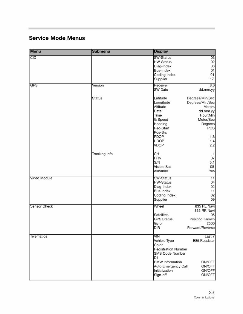
Service Mode Menus
Menu Submenu Display
CID SW-Status 03HW-Status 02Diag-Index 03Bus-Index 01Coding Index 01Supplier 17
GPS Version
Status
Tracking Info
Receiver 8.6SW Date dd.mm.yy
Latitude Degrees/Min/SecLongitude Degrees/Min/SecAltitude MetersDate dd.mm.yyTime Hour:MinG Speed Meter/SecHeading DegreesRec-Start POSPos-Src PDOP 1.8HDOP 1.4VDOP 2.2
CH 1PRN 07S/N 5.1Visible Sat 08Almanac Yes
Video Module SW-Status 11HW-Status 04Diag-Index 02Bus-Index 11Coding Index 02Supplier 09
Sensor Check Wheel 835 RL Navi835 RR Navi
Satellites 05GPS Status Position KnownGyro 2500DIR Forward/Reverse
Telematics VIN Last 7Vehicle Type E85 RoadsterColorRegistration NumberSMS Code NumberD1BMW Information ON/OFFAuto Emergency Call ON/OFFInitialization ON/OFFSign-off ON/OFF
34Communications
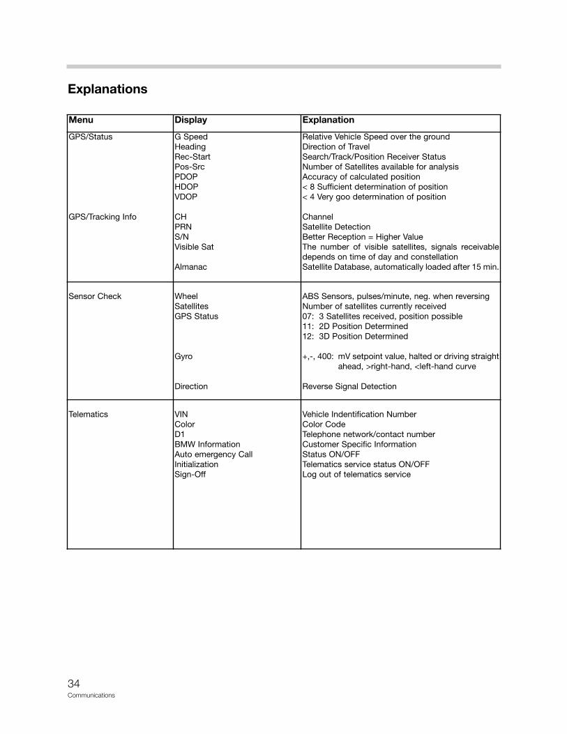
Explanations
Menu Display Explanation
GPS/Status
GPS/Tracking Info
G SpeedHeadingRec-StartPos-SrcPDOPHDOPVDOP
CHPRNS/NVisible Sat
Almanac
Relative Vehicle Speed over the groundDirection of TravelSearch/Track/Position Receiver StatusNumber of Satellites available for analysisAccuracy of calculated position< 8 Sufficient determination of position< 4 Very goo determination of position
ChannelSatellite DetectionBetter Reception = Higher ValueThe number of visible satellites, signals receivabledepends on time of day and constellationSatellite Database, automatically loaded after 15 min.
Sensor Check WheelSatellitesGPS Status
Gyro
Direction
ABS Sensors, pulses/minute, neg. when reversingNumber of satellites currently received07: 3 Satellites received, position possible11: 2D Position Determined12: 3D Position Determined
+,-, 400: mV setpoint value, halted or driving straight ahead, >right-hand, <left-hand curve
Reverse Signal Detection
Telematics VINColorD1BMW InformationAuto emergency CallInitializationSign-Off
Vehicle Indentification NumberColor CodeTelephone network/contact numberCustomer Specific InformationStatus ON/OFFTelematics service status ON/OFFLog out of telematics service
35Communications
Review Questions
1. Which radios are available as factory options in the Z4?
2. Which of the radio options are available with the Top-HiFi system?
3. What is the procedure for radio removal on vehicles equipped with the CID?
4. In case of a malfunction what portions of the CID may be replaced separately?
5. Where is the aerial diversity unit located?
6. What is the location of the Top-HiFi amplifier?
7. Why does the Navigation system now use a DVD player?
8. What is the location of the GPS aerial?


![MaxiDas BMW V8.20 Function List · 2014. 2. 26. · 3 Series E36[>9803] Body MRS/AB Airbag/ACSM 3 Series E36[>9803] Body BCO/MID On-board computer/MID 3 Series E36[>9803] Body CVM/CVM2](https://img.pdfslide.us/doc/110x75/60d6a868bb26a3223d33f458/maxidas-bmw-v820-function-list-2014-2-26-3-series-e369803-body-mrsab.jpg)

![Function List - Videntshop3 Series E36[>9803] Body IHKA Heater/automatic A/C control √ √ √ √ √ √ 3 Series E36[>9803] Body IR Radio/infrared locking system 3 Series E36[>9803]](https://img.pdfslide.us/doc/110x75/60d6a8bf00a997742a129fae/function-list-3-series-e369803-body-ihka-heaterautomatic-ac-control-a.jpg)