Embed Size (px)
Citation preview
GXG400-GXG410 3Gb/s, HD and SD up/down/cross converter and
synchronizer with optional audio shuffler
Installation and Operation manual

Hercules 28
NL-5126 RK Gilze
The Netherlands
Phone: +31 161 850 450
Fax: +31 161 850 499
E-mail: [email protected]
Web: www.axon.tv
TECHNICAL MANUAL
GXG400
GXG410

1
WARNING: TO REDUCE THE RISK OF FIRE OR
ELECTRICAL SHOCK, DO NOT EXPOSE THIS
APPLIANCE TO RAIN OR MOISTURE
● ALWAYS disconnect your entire system from the AC mains before cleaning any component. The product
frame (SFR18 or SFR04) must be terminated with three-conductor AC mains power cord that includes an
earth ground connection. To prevent shock hazard, all three connections must always be used.
● NEVER use flammable or combustible chemicals for cleaning components.
● NEVER operate this product if any cover is removed.
● NEVER wet the inside of this product with any liquid.
● NEVER pour or spill liquids directly onto this unit.
● NEVER block airflow through ventilation slots.
● NEVER bypass any fuse.
● NEVER replace any fuse with a value or type other than those specified.
● NEVER attempt to repair this product. If a problem occurs, contact your local Axon distributor.
● NEVER expose this product to extremely high or low temperatures.
● NEVER operate this product in an explosive atmosphere.
Warranty: Axon warrants their products according to the warranty policy as described in the general terms.
That means that Axon Digital Design BV can only warrant the products as long as the serial numbers are not
removed.
Copyright © 2001 – 2015 AXON Digital Design B.V.
Date created: 24-02-2015
Date last revised: 07-09-2015
Axon, the Axon logo and Synapse are trademarks of Axon Digital Design B.V.
This product complies with the requirements of the product family standards for audio, video, audio-visual
entertainment lighting control apparatus for professional use as mentioned below.
EN60950
EN55103-1: 1996
EN55103-2: 1996
Safety
Emission
Immunity
Axon Digital Design
GXG200
HXH200
Tested To Comply
With FCC Standards
FOR HOME OR OFFICE USE
This device complies with part 15 of the FCC Rules
Operation is subject to the following two conditions:
(1) This device may cause harmful interference, and
(2) This device must accept any interference received, including
interference that may cause undesired operation.
2
Index
Introduction to Synapse 6 An Introduction to Synapse 6 Local Control Panel 6 Remote Control Capabilities 6
Unpacking and Placement 7 Unpacking 7 Placing the card 7
A Quick Start 8 When powering-up 8 Changing settings and parameters 8 Front Panel Control 8 Example of changing parameters using front panel control 9 Axon Cortex Software 10 Menu Structure Example 10
The GX400/GXG410 Card 11 Introduction 11 Features 11 Conversion capabilities 12 Applications 12 Block schematic 13 Important notice about closed captions 13
Settings Menu 14 Introduction 14 HDMI1-Format ~ HDMI2-Format 14 HDMI1-DVI-Mode ~ HDMI2-DVI-Mode 14 HDMI1-GrpA-Sel ~ HDMI2-GrpA-Sel 14 HDMI1-GrpB-Sel ~ HDMI2-GrpB-Sel 14 HDMI1-Mute-All ~ HDMI2-Mute-All 14 CVBS1-In-Format ~ CVBS4-In-Format 15 CVBS1-Input-Hue ~CVBS4-Input-Hue 15 IO-Ctrl 15 IO_Prst_Act 15 IO_Prst_Edit 15 PrstEditView 15 #Inp_SelA 15 #Out-FrmtA 16 #Output_Map_A 16 #4K_Map_A 16 #Out-Mode 16 #F-delayA 16 #V-delayA 17 #H-delayA 17 #Freeze_A 17 #LowPassFilt_A 17 #VANC_TransA 19 #VANC_Trans_Ln0A ~ #VANC_Trans_Ln5A 19 Pos-Prst_Act 19 Pos-Prst_edit 19 #H-Pos-A 19 #V-Pos-A 19 Lock-Mode 19 Delay-Status 19 Dolby-E-ModeA 19 PatternSpeed 20 WST-InsertA 20 S2031-EmbA 20 OP47-SDP-Emb_A 20 SD_AR-Det 20 NoWSS/VI_prstA 20 Input_Loss_A 21 Up_CtrlA 21 Up_Prst_actA 21 UP_Prst_editA 21
3
#Up_ArcA 21 #Up_H-scaleA 22 #Up_V-scaleA 22 #Up_H-EnhA 22 #Up_V-EnhA 22 #Up_ColorConvA 22 Dn_CtrlA 22 Dn_Prst_actA 22 Dn_Prst_editA 22 #Dn_ArcA 23 # Dn_H-scaleA 23 # Dn_V-scaleA 23 # Dn_H-EnhA 23 # Dn_V-EnhA 23 # Dn_ColorConvA 24 Cr_CtrlA 24 Cr_Prst_actA 24 Cr_Prst_editA 24 #Cr_ArcA 24 #Cr_H-scaleA 25 #Cr_V-scaleA 25 #Cr_H-EnhA 25 #Cr_V-EnhA 25 Tr_CtrlA 25 Tr_Prst_ActA 25 Tr_Prst_EditA 25 #Tr_ArcA 26 #Tr_H-scaleA 26 #Tr_V-scaleA 26 #Tr_H-EnhA 26 #Tr_V-EnhA 26 Timecode_insA 26 VITC_Ln_InA 26 VITC_Ln_CtrlA 26 VITC_Ln_625A 27 VITC_Ln_525A 27 VITC_Ln_DupA 27 ATC_Dem_SelA 27 ATC_Emb_SelA 27 Ins_CtrlA 27 Ins_Prst_ActA 27 Ins_Prst_EditA 27 #VI-InsertA 27 #VI-DataA 27 #WSS-InsertA 28 #WSS-StndA 28 #WSS-ExtndA 28 #VI-DataA 28 #S2016-InsertA 28 #S2016-LineA 28 #S2016-DataA 28 #CC_Ena_A 28 GainA 28 R-GainA 28 G-GainA 29 B-GainA 29 BlackA 29 R-BlackA 29 G-BlackA 29 B-BlackA 29 Note 29 Y_Gain 29 C_Gain 29 Audio_CtrlA 29 Audio_Prst_ActA 29 Audio_Prst_EditA 30 #Silence-TimeA 30 #Silence-LevelA 30 #Emb1_GrpSel 30 #Emb1_Ch01/04 30 #Emb1_Ch13/16 30 #Emb1_Gain01 ~ #Emb1_Gain16 31 #Emb1_Delay01 ~ #Emb1_Delay16 31 #Emb1_Phase01/16 31
4
Audio-PhaseA 32 IP_Conf0 32 mIP0 32 mNM0 32 mGW0 32 NetwPrefix0 32
Status Menu 33 Introduction 33 SFP1-Vendor 33 SFP1-Type 33 SFP1-Temp-Stat 33 SFP1-Volt-Stat 33 Port1/2-Enabled 33 Port1/2-Power 33 Port1/2-Power-Stat 33 Port1/2-Bias 33 Port1/2-Bias-Stat 33 Port1/2-Wavelength 33 SFP2-Vendor 34 SFP2-Type 34 SFP2-Temp-Stat 34 SFP2-Volt-Stat 34 Port3/4-Enabled 34 Port3/4-Power 34 Port3/4-Power-Stat 34 Port3/4-Bias 34 Port3/4-Bias-Stat 34 Port3/4-Wavelength 34 HDMI1-Vid-Std ~ HDMI2-Vid-Std 34 HDMI1-GrpInUse ~ HDMI2-GrpInUse 35 HDMI1-EDH-Stat ~ HDMI2-EDH-Stat 35 sInp1 35 ~ sInp2 35 sInpA 35 sInpA_VI 35 sInpA_WSS-Stnd 36 sInpA_WSS-Extd 36 sInpA_S2016 36 sInpA_CRC_EDH 36 sInpA_Map 37 sInpA_VITC 37 sInpA_ATC 37 S2031-WST-DetA 37 WST-DetA 37 OP47-Det-A 37 CC_Det_A 37 IODelayA 38 FunctionA 38 Ref-Format 38 GPI 38 GPIA 38 GPIB 38 GPIC 38 SDIADemFrmt01/02 ~ SDIADemFrmt15/16 38 EmbStat_A 39 AddOnFrmtInA1/2 ~ AddOnFrmtInD3/D4 39 AddOnFrmtIn01/02 ~ AddOnFrmtIn31/32 39 SOF-E_A1/2A ~ SOF-E_D3/4A 39 FPGA_Core_Temp 39 IP_Addr0 39 MAC0 40 IP0 40 NM0 40 GW0 40
Events Menu 41 Introduction 41 What is the Goal of an event? 41 Events 41 Announcements 41 Input_A 41 Input_B 41 Ref-Status 41 Active_Out_A 41
5
What information is available in an event? 41 The Message String 41 The Tag 42 Defining Tags 42 The Priority 42 The Address 42
LED Indication 43 Error LED 43 Input_x LED 43 ANC Data LED 43 Reference LED 43 Data Error LED 43 Connection LED 43
Block Schematic 44
Connector Panels 45
GPI Interface 46
Reprogramming GXGxxx modules 47 Before you start 47 Functionality explanation 47 Choosing .spf files 47 Requirements 47 Using Cortex help files 47 Precautions 48 Backup your settings 48 At your own risk 48 Setting up card 49 Testing 51
GNU Public License version 2 52
6
1 Introduction to Synapse
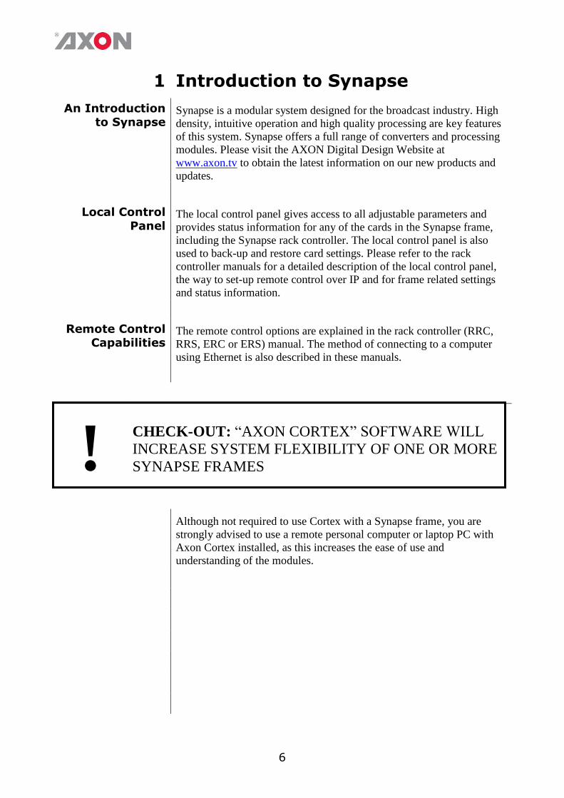
An Introduction to Synapse
Synapse is a modular system designed for the broadcast industry. High
density, intuitive operation and high quality processing are key features
of this system. Synapse offers a full range of converters and processing
modules. Please visit the AXON Digital Design Website at
www.axon.tv to obtain the latest information on our new products and
updates.
Local Control
Panel The local control panel gives access to all adjustable parameters and
provides status information for any of the cards in the Synapse frame,
including the Synapse rack controller. The local control panel is also
used to back-up and restore card settings. Please refer to the rack
controller manuals for a detailed description of the local control panel,
the way to set-up remote control over IP and for frame related settings
and status information.
Remote Control Capabilities
The remote control options are explained in the rack controller (RRC,
RRS, ERC or ERS) manual. The method of connecting to a computer
using Ethernet is also described in these manuals.
! CHECK-OUT: “AXON CORTEX” SOFTWARE WILL
INCREASE SYSTEM FLEXIBILITY OF ONE OR MORE
SYNAPSE FRAMES
Although not required to use Cortex with a Synapse frame, you are
strongly advised to use a remote personal computer or laptop PC with
Axon Cortex installed, as this increases the ease of use and
understanding of the modules.
7
2 Unpacking and Placement
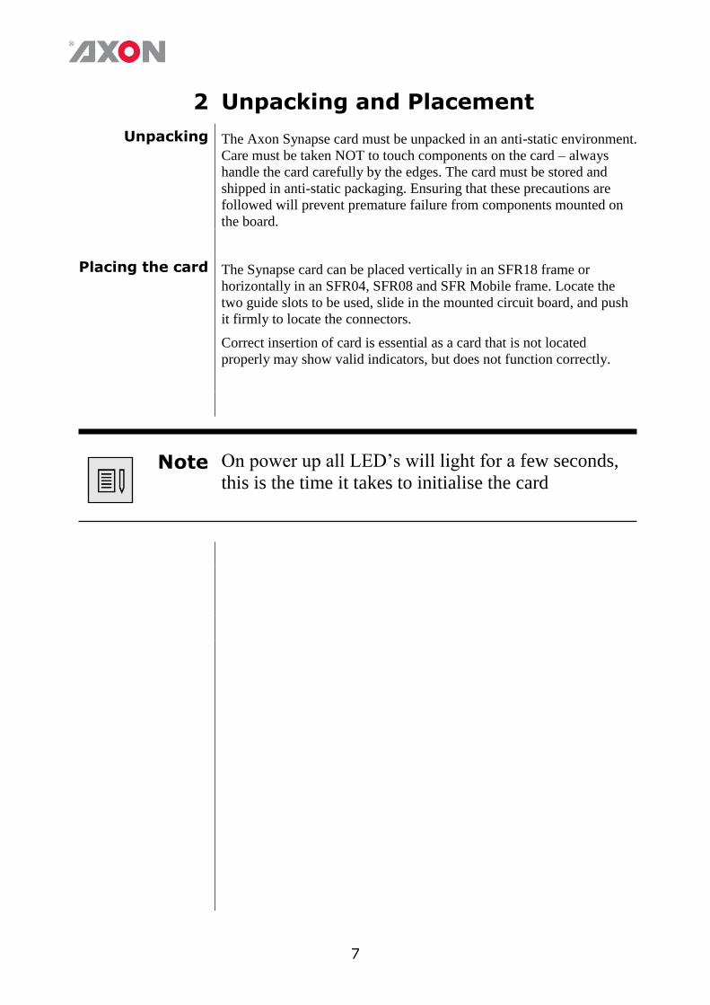
Unpacking The Axon Synapse card must be unpacked in an anti-static environment.
Care must be taken NOT to touch components on the card – always
handle the card carefully by the edges. The card must be stored and
shipped in anti-static packaging. Ensuring that these precautions are
followed will prevent premature failure from components mounted on
the board.
Placing the card The Synapse card can be placed vertically in an SFR18 frame or
horizontally in an SFR04, SFR08 and SFR Mobile frame. Locate the
two guide slots to be used, slide in the mounted circuit board, and push
it firmly to locate the connectors.
Correct insertion of card is essential as a card that is not located
properly may show valid indicators, but does not function correctly.
Note On power up all LED’s will light for a few seconds,
this is the time it takes to initialise the card
8
3 A Quick Start
When powering-up
On powering up the Synapse frame, the card set will use basic data and
default initialisation settings. All LED’s will light during this process.
After initialisation, several LED’s will remain lit – the exact number
and configuration is dependent upon the number of inputs connected
and the status of the inputs.
Changing
settings and parameters
The front panel controls or the Synapse Cortex can be used to change
settings. An overview of the settings can be found in chapter 5, 6 and 7
of this manual.
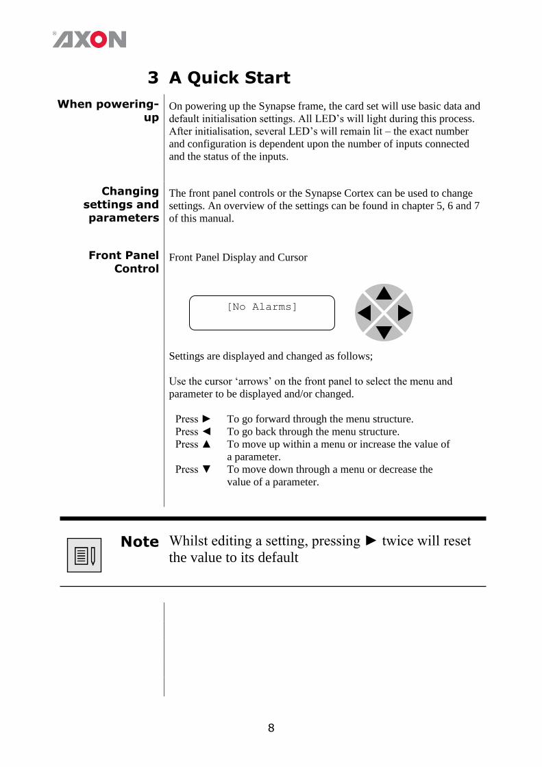
Front Panel
Control Front Panel Display and Cursor
Settings are displayed and changed as follows;
Use the cursor ‘arrows’ on the front panel to select the menu and
parameter to be displayed and/or changed.
Press ► To go forward through the menu structure.
Press ◄ To go back through the menu structure.
Press ▲ To move up within a menu or increase the value of
a parameter.
Press ▼ To move down through a menu or decrease the
value of a parameter.
Note Whilst editing a setting, pressing ► twice will reset
the value to its default
[No Alarms]
9
Example of changing
parameters using front
panel control
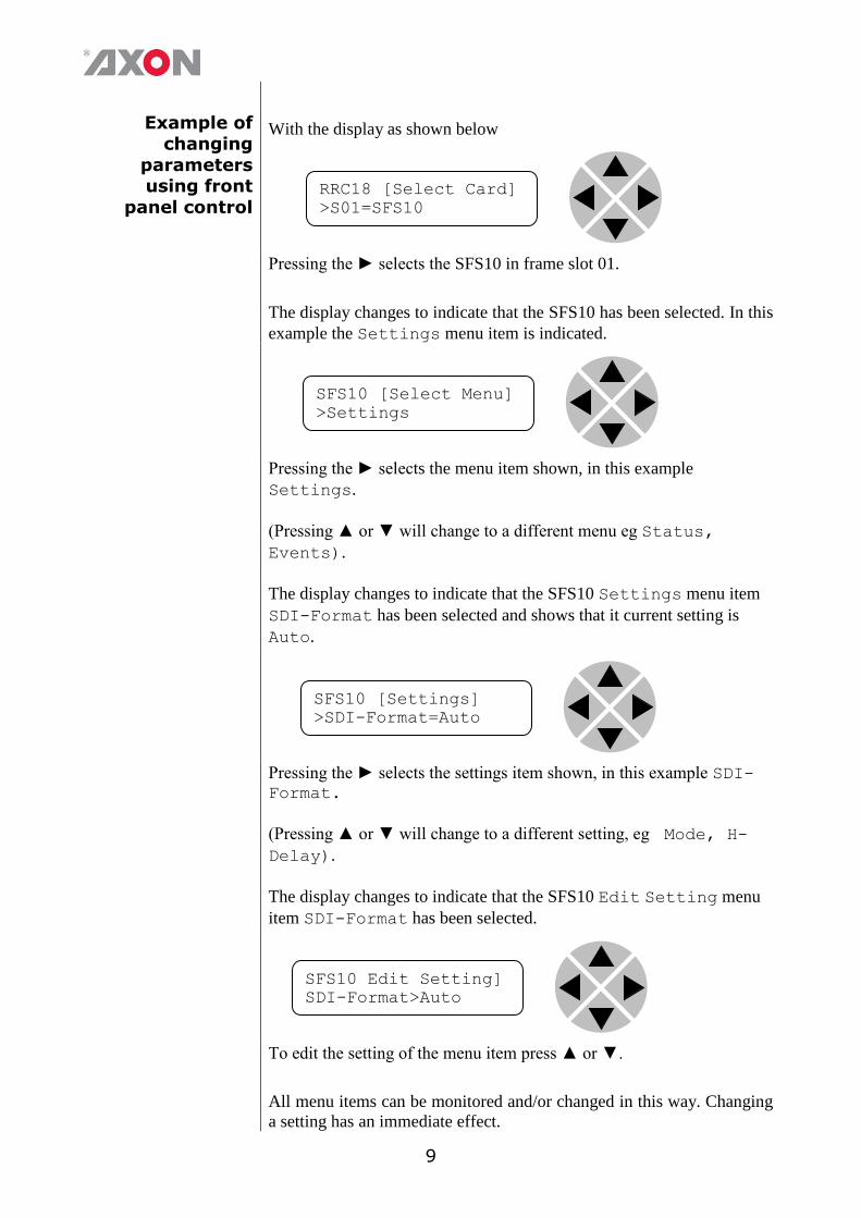
With the display as shown below
Pressing the ► selects the SFS10 in frame slot 01.
The display changes to indicate that the SFS10 has been selected. In this
example the Settings menu item is indicated.
Pressing the ► selects the menu item shown, in this example
Settings.
(Pressing ▲ or ▼ will change to a different menu eg Status,
Events).
The display changes to indicate that the SFS10 Settings menu item
SDI-Format has been selected and shows that it current setting is
Auto.
Pressing the ► selects the settings item shown, in this example SDI-Format.
(Pressing ▲ or ▼ will change to a different setting, eg Mode, H-
Delay).
The display changes to indicate that the SFS10 Edit Setting menu
item SDI-Format has been selected.
To edit the setting of the menu item press ▲ or ▼.
All menu items can be monitored and/or changed in this way. Changing
a setting has an immediate effect.
RRC18 [Select Card]
>S01=SFS10
SFS10 [Select Menu]
>Settings
SFS10 [Settings]
>SDI-Format=Auto
SFS10 Edit Setting]
SDI-Format>Auto
10
Axon Cortex Software
Synapse Cortex can be used to change the settings of Synapse modules
from a PC, either locally or remotely. The software enables
communication based on TCP/IP between the Setup PC and Synapse
frames/modules.
Each Synapse frame is addressed through its rack controller’s unique IP
address, giving access to each module, its menus and adjustment items.
Axon Cortex has access to data contained within the Synapse module
and displays it on a GUI. The software has an intuitive structure
following that of the module that it is controlling.
For operation of Axon Cortex, please refer to the Cortex help files.
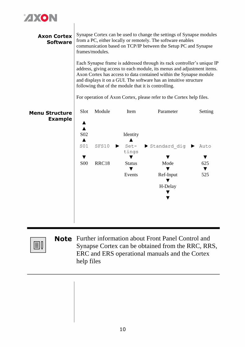
Menu Structure Example
Slot Module Item Parameter Setting
▲
▲
S02 Identity
▲ ▲
S01 SFS10 ► Set-
tings
► Standard_dig ► Auto
▼ ▼ ▼ ▼
S00 RRC18 Status Mode 625
▼ ▼ ▼
Events Ref-Input 525
▼
H-Delay
▼
▼
Note Further information about Front Panel Control and
Synapse Cortex can be obtained from the RRC, RRS,
ERC and ERS operational manuals and the Cortex
help files
11
4 The GX400/GXG410 Card
Introduction The GXG400/410 is a high end up/down/cross converter. Based on
Axon's Motion Optimized Quality De-interlacer (MOQD), and
extensively computer optimized scaling and filter algorithms the new
400 series of up/down/cross converters ensure the absolute best quality
video conversion from any standard to any standard within the same
framerate. The card allows you to simulcast any output standard in any
format from any source standard.
The embedded audio is carried over to the SD, HD or 3Gb/s domain.
The appropriate aspect ratio can be applied by control of VI, WSS and
GPI inputs by use of 16 presets per output that can store the aspect
ratio conversions.
Beside a high quality up/down/cross converter, these cards also have
very powerful audio shufflers and proc-amps (410 only). Any of the 64
audio source channels (16 from SDI 1, and 32 from the quad speed
audio bus) can be routed to any of the 48 output channels (16 to SDI
output 1 and 32 to the quad speed audio bus)
Features
Industry highest quality de-interlacing algorithm using Axon's
MOQD
3Gb/s signals level A and level B compatible
Compatible with the following formats
1080p/59.94
1080p/50
1080i/59.94
1080i/50
1080p/29.97
1080p/25
720p/59.94
720p/50
SD525
SD625
Regardless of the conversion, every conversion will have a constant
latency.
Multiple external Inputs and Outputs
4 SDI inputs and outputs
Up to 4 optional extra inputs/outputs by use of 2 SFP cages
(fiber or coaxial, CVBS and HDMI) 10Gb/s Ethernet connection for future use of Ethernet based
video like AVB
7 configurable GPI I/O contacts
Ethernet for control LTC and Metadata input
Frame synchronizer with auto-phaser and control in Frames, Lines
and pixels with respect to reference.
All ARC modes contain Anamorphic, Center Cut, V-Zoom, LBox-
16:9, LBox-14:9, PBox-4:3, PBox-14:9 and Variable H and V (50-
200%)
12
16 free individual programmable preset banks with settings for:
Down conversion, Up conversion and Cross conversion
Transparent pass through (with ARC function)
Simultaneous VI, WSS and AFD (S2016) insertion
Embedder shuffling, gain and phase (in GXG410 only)
audio delay setting (in GXG410 only)
ARC triggers by VI, WSS, WSS-ext and S2016 (AFD)
Transparent for 16 channels of embedded audio per video channel
Embedded domain 64x64 routing to and from the individual
in/outputs and Quad Speed Audio Bus (410 only)
Video proc-amp (Y and C control)
Color corrector (RGB and total gain, RGB and total black)
Medium latency conversion process (2 frames)
Quad Speed Embedding and de-embedding through synapse bus
Locks to Tri-level, Bi-level or SDI input 1 or 2
Full control and status monitoring through the front panel of the
SFR04/SFR08/SFR18 frame and the Ethernet port (ACP)
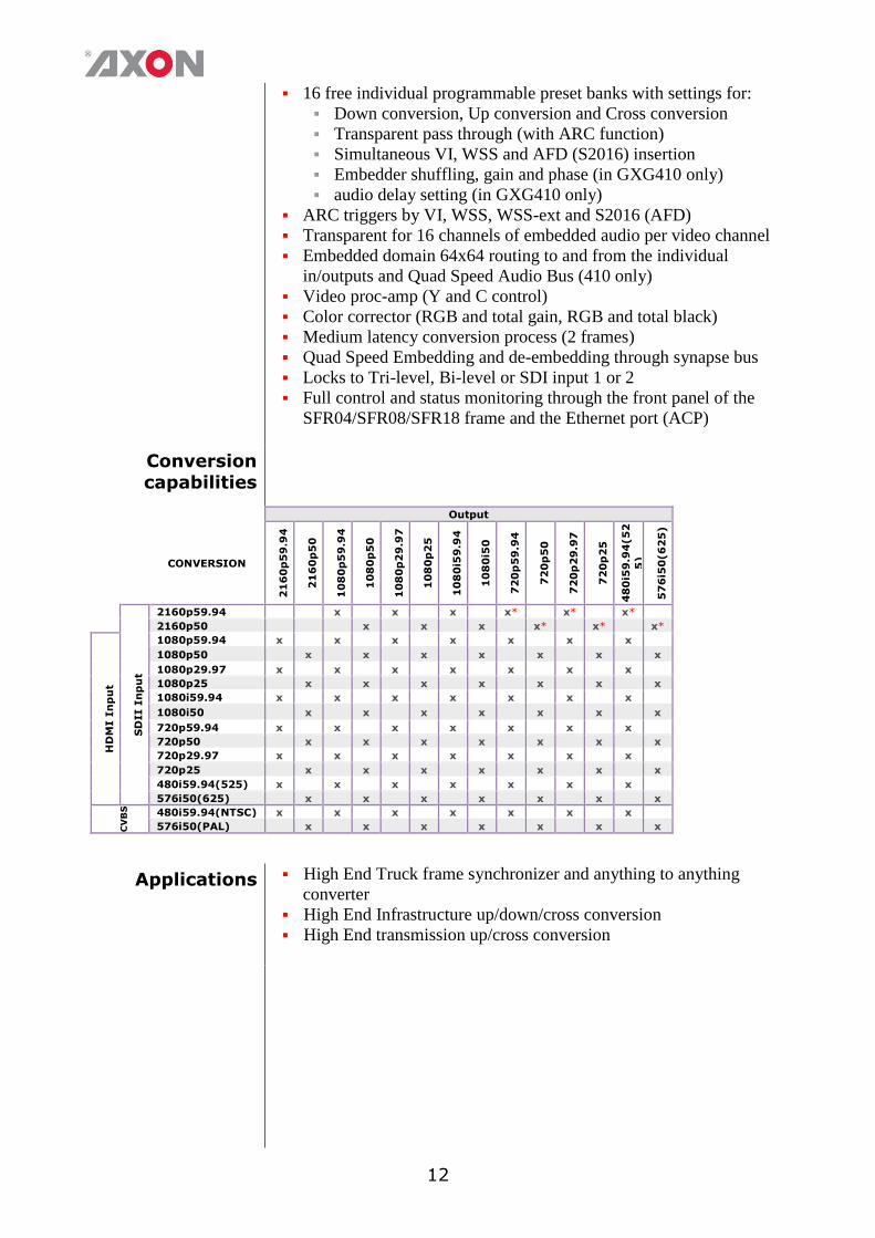
Conversion capabilities
Output
CONVERSION
21
60
p5
9.9
4
21
60
p5
0
10
80
p5
9.9
4
10
80
p5
0
10
80
p2
9.9
7
10
80
p2
5
10
80
i59
.94
10
80
i50
72
0p
59
.94
72
0p
50
72
0p
29
.97
72
0p
25
48
0i5
9.9
4(5
2
5)
57
6i5
0(6
25
)
SD
II I
np
ut
2160p59.94 x x x x* x* x*
2160p50 x x x x* x* x*
HD
MI I
np
ut
1080p59.94 x x x x x x x
1080p50 x x x x x x x
1080p29.97 x x x x x x x
1080p25 x x x x x x x
1080i59.94 x x x x x x x
1080i50 x x x x x x x
720p59.94 x x x x x x x
720p50 x x x x x x x
720p29.97 x x x x x x x
720p25 x x x x x x x
480i59.94(525) x x x x x x x
576i50(625) x x x x x x x
CV
BS
480i59.94(NTSC) x x x x x x x
576i50(PAL) x x x x x x x
Applications High End Truck frame synchronizer and anything to anything
converter
High End Infrastructure up/down/cross conversion
High End transmission up/cross conversion
13
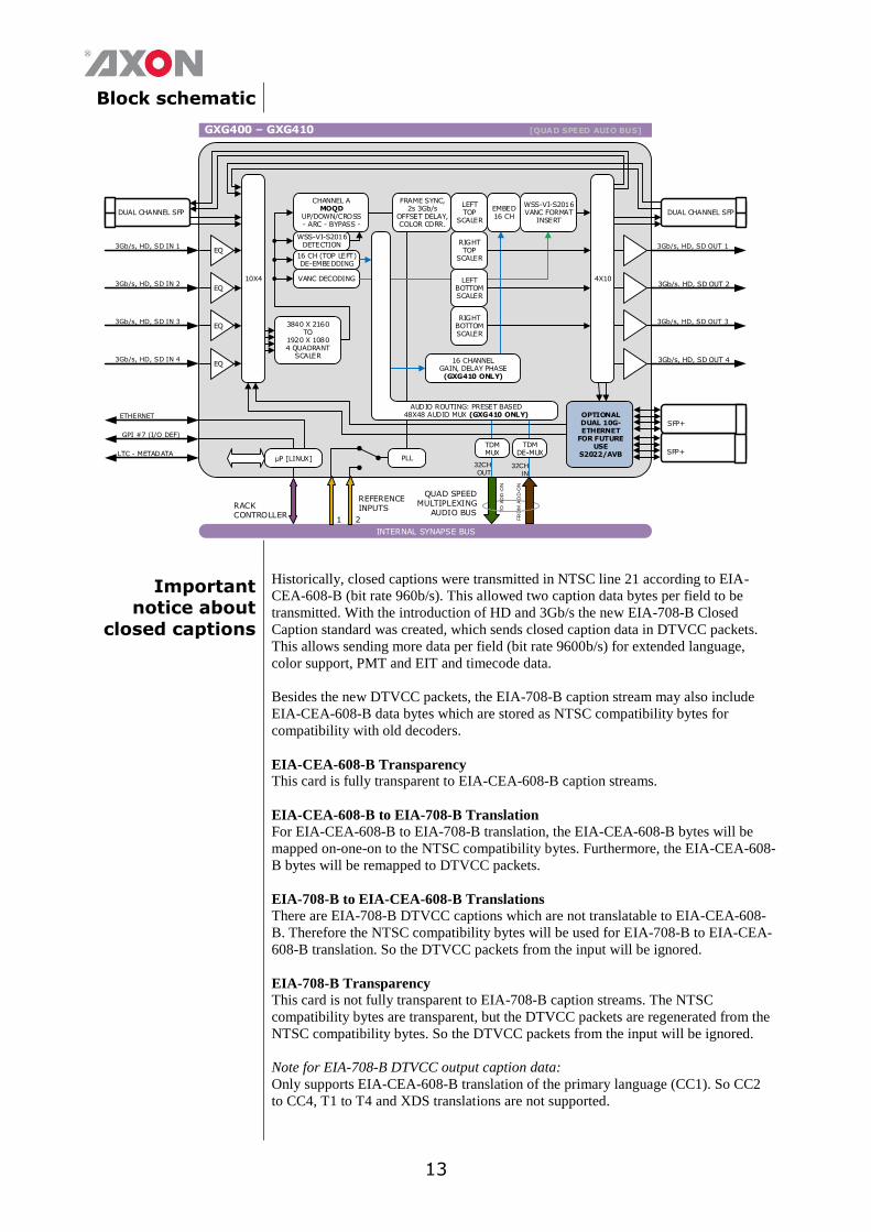
Block schematic
INTERNAL SYNAPSE BUS
GXG400 – GXG410 [QUAD SPEED AUIO BUS]
RACK CONTROLLER
REFERENCEINPUTS
1 2
µP [LINUX]
CHANNEL AMOQD
UP/DOWN/CROSS- ARC - BYPASS -
PLL
WSS-VI-S2016DETECTION
EQ
EQ
3Gb/s. HD, SD OUT 2
3Gb/s, HD, SD OUT 4
DUAL CHANNEL SFP
4X10
16 CH (TOP LEFT) DE-EMBEDDING
EMBED16 CH
WSS-VI-S2016VANC FORMAT
INSERT
16 CHANNELGAIN, DELAY PHASE(GXG410 ONLY)
QUAD SPEED MULTIPLEXING
AUDIO BUS
32CHOUT
32CHIN
TO
AD
D-O
N
FR
OM
AD
D-O
N
FRAME SYNC,2s 3Gb/s
OFFSET DELAY,COLOR CORR.
LEFT TOP
SCALER
TDMMUX
TDMDE-MUX
DUAL CHANNEL SFP
VANC DECODING
AUDIO ROUTING: PRESET BASED48X48 AUDIO MUX (GXG410 ONLY)
SFP+
EQ
EQ
OPTIONAL DUAL 10G-ETHERNET
FOR FUTURE USE
S2022/AVB
RIGHT TOP
SCALER
LEFT BOTTOM SCALER
RIGHT BOTTOM SCALER
10X4
3840 X 2160TO
1920 X 10804 QUADRANT
SCALER
SFP+
Important notice about
closed captions
Historically, closed captions were transmitted in NTSC line 21 according to EIA-
CEA-608-B (bit rate 960b/s). This allowed two caption data bytes per field to be
transmitted. With the introduction of HD and 3Gb/s the new EIA-708-B Closed
Caption standard was created, which sends closed caption data in DTVCC packets.
This allows sending more data per field (bit rate 9600b/s) for extended language,
color support, PMT and EIT and timecode data.
Besides the new DTVCC packets, the EIA-708-B caption stream may also include
EIA-CEA-608-B data bytes which are stored as NTSC compatibility bytes for
compatibility with old decoders.
EIA-CEA-608-B Transparency
This card is fully transparent to EIA-CEA-608-B caption streams.
EIA-CEA-608-B to EIA-708-B Translation
For EIA-CEA-608-B to EIA-708-B translation, the EIA-CEA-608-B bytes will be
mapped on-one-on to the NTSC compatibility bytes. Furthermore, the EIA-CEA-608-
B bytes will be remapped to DTVCC packets.
EIA-708-B to EIA-CEA-608-B Translations
There are EIA-708-B DTVCC captions which are not translatable to EIA-CEA-608-
B. Therefore the NTSC compatibility bytes will be used for EIA-708-B to EIA-CEA-
608-B translation. So the DTVCC packets from the input will be ignored.
EIA-708-B Transparency
This card is not fully transparent to EIA-708-B caption streams. The NTSC
compatibility bytes are transparent, but the DTVCC packets are regenerated from the
NTSC compatibility bytes. So the DTVCC packets from the input will be ignored.
Note for EIA-708-B DTVCC output caption data:
Only supports EIA-CEA-608-B translation of the primary language (CC1). So CC2
to CC4, T1 to T4 and XDS translations are not supported.
14
5 Settings Menu
Introduction The settings menu displays the current state of each GXG4x0 setting
and allows you to change or adjust it. Settings can be changed using
the front panel of the Synapse frame (SFR18, SFR08 or SFR04) or
with Cortex. Also the SCP08 control can be used. Please refer to
chapter 3 for information on the Synapse front panel control and
Cortex.
Note: All items preceded with a #-sign are part of the presets.
HDMI
HDMI1-Format ~
HDMI2-Format Here you select the output format of the corresponding HDMI output
module. Possible modes are
■ RGB444 (default) ■ YCrCb422
■ YCrCb444
HDMI1-DVI-Mode
~ HDMI2-DVI-
Mode
With these settings you set the corresponding HDMI output to either
DVI-Mode or HDMI-Mode. Default is DVI-Mode.
HDMI1-GrpA-Sel ~
HDMI2-GrpA-Sel The HDMI outputs can contain 2 groups of audio. Here you select
which input group should be in group A of the corresponding HDMI
output. Can be group 1, 2 3 or 4. Default is Group 1.
HDMI1-GrpB-Sel ~
HDMI2-GrpB-Sel The HDMI outputs can contain 2 groups of audio. Here you select
which input group should be in group B of the corresponding HDMI
output. Can be group 1, 2 3 or 4. Default is Group 2.
HDMI1-Mute-All ~
HDMI2-Mute-All Here you can mute all audio on the corresponding HDMI output. Off
means no audio mute. On means all audio is muted. Default is off.
15
CVBS
CVBS1-In-Format
~ CVBS4-In-
Format
With these settings you select the analog input format of the
corresponding CVBS input. Possible formats are:
■ PAL-BGHID (default)
■ PAL-N
■ NTSC-M
■ PAL-M
■ NTSC-4.43
■ NTSC-J
■ PAL-60
CVBS1-Input-Hue
~CVBS4-Input-Hue Sets the Hue of the CVBS SFP input module. Can be set between -90
and 90. Default is 0.
IO-Ctrl This function isn’t currently not accessible but will be enabled in a
software release in the future.
IO_Prst_Act With this item you can manually change the currently active IO
settings. Can be any preset between 1 and 8. By default it is set to 1.
All menu settings that are preceded with a ‘# ‘-prefix under the
‘SYSTEM SETTINGS’ header are part of the preset.
IO_Prst_Edit Here you can select which of the 8 selectable IO settings presets you
want to edit. Changing this will not change the active preset, unless the
currently active preset is the same you are going to edit. All menu
settings that are preceded with a ‘# ‘-prefix under the ‘SYSTEM
SETTINGS’ header are part of the preset.
PrstEditView With this setting set to Follow Active, the edit preset settings (like
for instance UP_Prst_editA and UP_Prst_editB) will follow
the active preset when the active preset is changed. This to avoid
confusion when changing the active. Set to Independent the edit
preset will not automatically follow active preset changes. By default
set to Follow Active.
#Inp_SelA With this item you can select which input you want to use for Channel
A. It is possible to select physical inputs; SDI-1, SDI-2, SDI-3, SDI-4, SFP1-1, SFP1-1, SFP1-2, SFP2-1, SFP2-2,
SFP-4K or SDI-4K.You can also choose a Zoneplate or
Colorbar as input. The default for this setting is SDI-1.
16
#Out-FrmtA With Out-Frmt you can set what the output should be of channel A
as well as channel B. Possible settings are:
2160p50, 2160p60
1080i60 (default), 1080i50
1080p50, 1080p60
1080p30, 1080p25
720p60, 720p50
720p30, 720p25
SD525, SD625
#Output_Map_A This sets the output mapping of channel A. Level-A and Level-B
are the possible settings. Level-A is default.
#4K_Map_A This sets the 4K mapping. Currently the options are 4Ch-
4Quadrants or 4Ch-SI. More options will be added in future
releases.
#Out-Mode Sets the output mode. Currently fixed to A Only. More options will
be added in future releases.
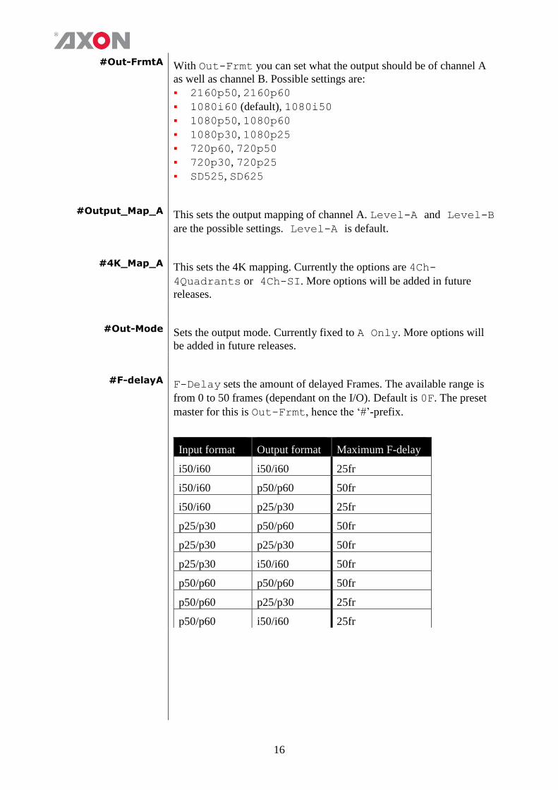
#F-delayA F-Delay sets the amount of delayed Frames. The available range is
from 0 to 50 frames (dependant on the I/O). Default is 0F. The preset
master for this is Out-Frmt, hence the ‘#’-prefix.
Input format Output format Maximum F-delay
i50/i60 i50/i60 25fr
i50/i60 p50/p60 50fr
i50/i60 p25/p30 25fr
p25/p30 p50/p60 50fr
p25/p30 p25/p30 50fr
p25/p30 i50/i60 50fr
p50/p60 p50/p60 50fr
p50/p60 p25/p30 25fr
p50/p60 i50/i60 25fr
17
#V-delayA V-Delay setting allows adjustment of the vertical phase of the output
signal with respect to the selected reference input.
The V-Delay setting gives a delay in addition to the reference timing.
For example: if the V-Delay is set to 10 TV HD lines, the output
signal will be delayed by reference timing + 10 TV HD lines. The
signal is delayed (advanced) with respect to the phase of the reference
signal. The available range is from 0 to a maximum of 1124 lines
(dependant on I/O format). The default setting is 0ln. The preset
master for this is Out-Frmt, hence the ‘#’-prefix.
#H-delayA The H-Delay setting allows adjustment of the Horizontal phase of the
output signal with respect to the selected reference input.
The H-Delay setting gives a delay in addition to the reference timing.
For example: if the H-Delay is set to 10 pixels, the output signal will be
delayed by reference timing + 10 pixels. The signal is delayed
(advanced) with respect to the phase of the reference signal. The
available range is from 0 to a maximum of 5124 pixels (dependant on
I/O format). The default setting is 0px. The preset master for this is
Out-Frmt, hence the ‘#’-prefix.
#Freeze_A Freeze enables the capture of one Video Frame. The settings of
Freeze are On or Off. The default setting is Off.
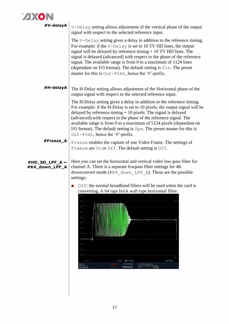
#HD_SD_LPF_A ~
#K4_down_LPF_A
Here you can set the horizontal and vertical video low-pass filter for
channel A. There is a separate lowpass filter settings for 4K
downconvert mode (#K4_down_LPF_A). These are the possible
settings:
■ Off: the normal broadband filters will be used when the card is
converting. A 64 taps brick wall type horizontal filter:
18
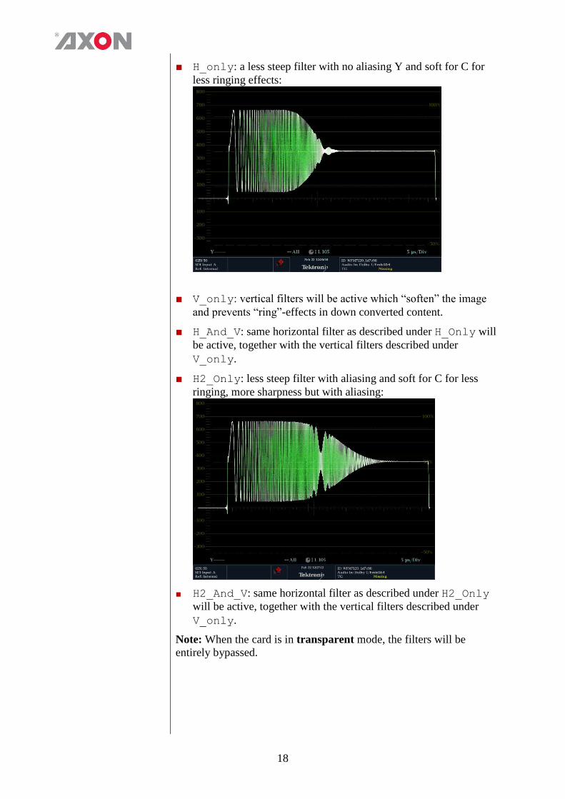
■ H_only: a less steep filter with no aliasing Y and soft for C for
less ringing effects:
■ V_only: vertical filters will be active which “soften” the image
and prevents “ring”-effects in down converted content.
■ H_And_V: same horizontal filter as described under H_Only will
be active, together with the vertical filters described under
V_only.
■ H2_Only: less steep filter with aliasing and soft for C for less
ringing, more sharpness but with aliasing:
■ H2_And_V: same horizontal filter as described under H2_Only
will be active, together with the vertical filters described under
V_only.
Note: When the card is in transparent mode, the filters will be
entirely bypassed.
19
#VANC_TransA Enables or disables the transfer from input to output of selected
Vertical Ancillary (VANC) lines. When the input format is the same as
the output format, the card is able to carry up to 6 lines containing
packets inserted in the Luminance Channel of the Vertical Ancillary
space to the output. With settings #VANC_Trans_Ln0 to
#VANC_Trans_Ln5 the user may select which lines to carry through
to the output. The possible settings of #VANC_Trans are On or Off.
The default setting is Off.
#VANC_Trans_Ln0A ~
#VANC_Trans_Ln5A
Selects a line to carry from input to output. You can choose 5 lines.
Refer to #VANC_Trans. Can be any line from line 7 through 41. If
for instance line 7 is selected, line 7 from the input is carried to line 7
at the output.
Pos-Prst_Act This function isn’t currently not accessible but will be enabled in a
software release in the future.
Pos-Prst_edit This function isn’t currently not accessible but will be enabled in a
software release in the future.
#H-Pos-A This function isn’t currently not accessible but will be enabled in a
software release in the future.
#V-Pos-A This function isn’t currently not accessible but will be enabled in a
software release in the future.
Lock-Mode Lock-Mode determines whether the card is locked to his input
(input 1), to the reference (Ref1 or Ref2)
Delay-Status It is possible to display (in the status menu IODelayA and
IODelayB) the processing time of the card in the status menu. This
setting allows you to switch this function On or Off. Default setting is Off
Dolby-E-ModeA With this setting you can turn the Dolby-E alignment on or off. If this
setting is set to Align, the card will correct any offset between -0,5
frame and +0,5 frame automatically. This correction will be added to
the audio delay which is needed to track the video delay (IO-delay). If
this setting is set to Off, the Dolby-E will be handled transparently.
The Dolby-E will be aligned according the Dolby-E recommended line
positions, which are output format dependant.
Note: Assumes all Dolby E pairs from the de-embedded SDI input are
aligned with reference to each other.
20
PatternSpeed Sets the speed of the test-pattern (see settings Inp_SelA and
Inp_SelB) animation between 0 (still) and 15 (fast). Default 1.
WST-InsertA Disables or Enables WST insertion in SD formats
S2031-OP47-DecA With this setting you select which input source of channel A will be
decoded. Can be set to Auto, S2031 or OP47. When set to Auto, the
input source which is available will be selected. Default is Auto.
Note: When both S2031 and OP47 sources are available at the input,
only S2031 will be decoded (S2031 has priority over OP47).
S2031-OP47-EncA With this setting you select if OP47 or S2031 of channel A will be
encoded for HD and 3Gb/s output formats. Can be set to Off, S2031
or OP47. When Off is selected, nothing will be inserted. Default is
Off.
S2031-EmbA With this setting you set in which line of channel A the S2031 data
should be inserted. Can be any line between line 8 (def.) and line 16.
S2031-WST-DefA This setting is only applicable for a S2031 input source containing
undefined WST lines which are translated to a WST or OP47 output.
WST lines (which are packetized in S2031) are called undefined when
having line number 0. For such lines it is free during translation to
WST to decide in which WST line numbers they will be inserted. In
our case the setting S2031-WST-defA will define the start WST line
number of channel A, which will continuously be followed by other
WST lines. Can be any line between line 7 and line 22. Default is line
7.
OP47-SDP-Emb_A With this setting you set in which line the OP47 data of channel A
should be inserted. Can be any line between line 8 and line 16. Default
is 8.
SD_AR-Det This card can switch between presets on the change of the aspect ratio.
Aspect ratio information can be taken out of the VI (video index), WSS
(widescreen signaling) or WSS-extended (extended form of
widescreen signaling). With this setting you can select which of the
above protocols should be used to detect aspect ratio changes. This
settings influences the corresponding statuses eq when set to VI only
the sInpA_VI status is updated. By default it is set to VI.
NoWSS/VI_prstA With this setting you can set to which preset the card should jump
channel A, when no WSS or VI information is found. Can be any
preset between 1 and 16 or Hold (holds current active preset). By
default it is set to Hold.
21
Input_Loss_A Here you can set what the output of channel A should be when the
input is lost. Can be Freeze, Colorbar, Zoneplate, Black,
Grey or Green.
UP-CONV
Up_CtrlA With this item you select how the presets for Channel A in up
converter mode are controlled: Manually (manual), via GPI-triggers
(GPI, GPI-A, GPI-B or GPI-C) or via changes of the SD Aspect
Ratio (SD-AR). By default it is set to Manual.
Up_Prst_actA With this item you can manually change the currently active preset of
channel A in up converter mode. Can be any preset between 1 and 16.
By default it is set to 1. All menu settings that are preceded with a
‘#Up‘-prefix are part of the preset.
UP_Prst_editA Here you can select which of the 16 selectable presets you want to edit
for Channel A in up converter mode. Changing this will not change the
active preset, unless the currently active preset is the same you are
going to edit. All menu settings that are preceded with a ‘#Up‘-prefix
are part of the preset.
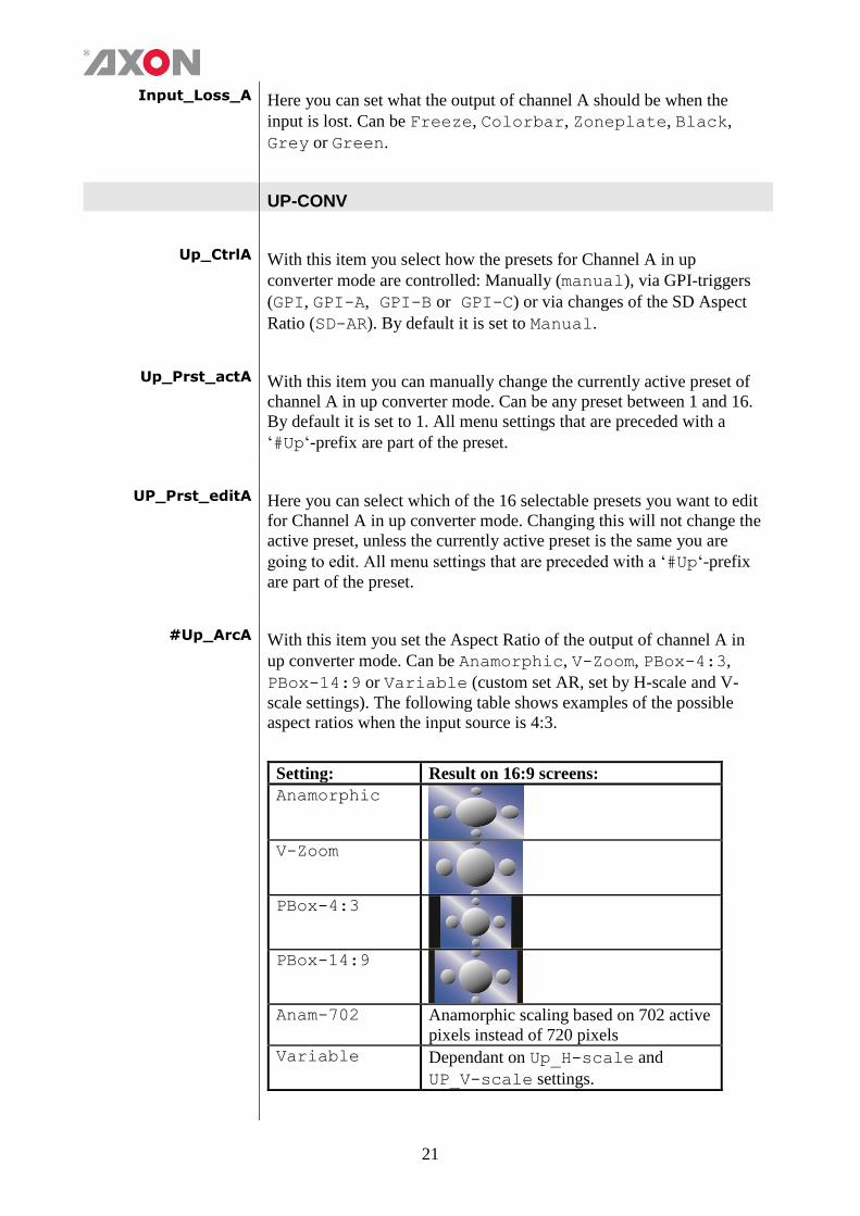
#Up_ArcA With this item you set the Aspect Ratio of the output of channel A in
up converter mode. Can be Anamorphic, V-Zoom, PBox-4:3,
PBox-14:9 or Variable (custom set AR, set by H-scale and V-
scale settings). The following table shows examples of the possible
aspect ratios when the input source is 4:3.
Setting: Result on 16:9 screens:
Anamorphic
V-Zoom
PBox-4:3
PBox-14:9
Anam-702 Anamorphic scaling based on 702 active
pixels instead of 720 pixels
Variable Dependant on Up_H-scale and
UP_V-scale settings.

22
#Up_H-scaleA The horizontal scaling of the TV picture of channel A in up converter
mode is set using #Up_H-scaleA. #Up_H-scaleA can be set
within the range of 50% to 200% of the input signal (only used when
#Up_ArcA is set to variable). Default value is 100%.
#Up_V-scaleA Sets the vertical scaling of the TV picture of channel A in up converter
mode. Can be set within the range of 50% to 200% of the input signal
(only used when #Up_ArcA is set to variable). Default value is
100%.
#Up_H-EnhA With this item you can set the horizontal picture enhancement of
channel A in up converter mode between 0 and 100%. By default set to
0%.
#Up_V-EnhA With this item you can set the vertical picture enhancement of channel
A in up converter mode between 0 and 100%. By default set to 0%.
#Up_ColorConvA ColorConvA optimizes the color conversion for Channel A in up
converter mode. As the color coding of HD (709) and
SD(601) are different, it is necessary to convert these when Channel A
is up-converting. The best result is generated when the up-converter is
active and the 601to709 setting is selected. It is also possible to
switch the filter off. The default setting is 601to709.
DOWN-CONV
Dn_CtrlA With this item you select how the presets for Channel A are controlled
in down converter mode: Manually (manual), via GPI-triggers (GPI,
GPI-A, GPI-B or GPI-C) or via changes of the HD Aspect Ratio
(S2016). By default it is set to Manual.
Dn_Prst_actA With this item you can manually change the currently active preset of
channel A in down converter mode. Can be any preset between 1 and
16. By default it is set to 1. All menu settings that are preceded with a
‘#Dn‘-prefix are part of the preset.
Dn_Prst_editA Here you can select which of the 16 selectable presets you want to edit
for Channel A in down converter mode. Changing this will not change
the active preset, unless the currently active preset is the same you are
going to edit. All menu settings that are preceded with a ‘#Dn‘-prefix
are part of the preset.
23
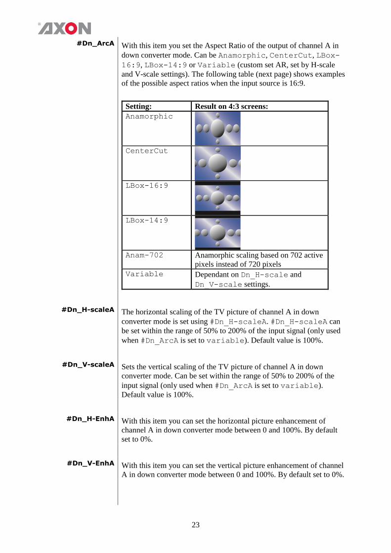
#Dn_ArcA With this item you set the Aspect Ratio of the output of channel A in
down converter mode. Can be Anamorphic, CenterCut, LBox-
16:9, LBox-14:9 or Variable (custom set AR, set by H-scale
and V-scale settings). The following table (next page) shows examples
of the possible aspect ratios when the input source is 16:9.
Setting: Result on 4:3 screens:
Anamorphic
CenterCut
LBox-16:9
LBox-14:9
Anam-702 Anamorphic scaling based on 702 active
pixels instead of 720 pixels
Variable Dependant on Dn_H-scale and
Dn_V-scale settings.
#Dn_H-scaleA The horizontal scaling of the TV picture of channel A in down
converter mode is set using #Dn_H-scaleA. #Dn_H-scaleA can
be set within the range of 50% to 200% of the input signal (only used
when #Dn_ArcA is set to variable). Default value is 100%.
#Dn_V-scaleA Sets the vertical scaling of the TV picture of channel A in down
converter mode. Can be set within the range of 50% to 200% of the
input signal (only used when #Dn_ArcA is set to variable).
Default value is 100%.
#Dn_H-EnhA With this item you can set the horizontal picture enhancement of
channel A in down converter mode between 0 and 100%. By default
set to 0%.
#Dn_V-EnhA With this item you can set the vertical picture enhancement of channel
A in down converter mode between 0 and 100%. By default set to 0%.
24
# Dn_ColorConvA ColorConvA optimizes the color conversion of channel A in down
converter mode. As the color coding of HD (709) and SD (601) are
different, it is necessary to convert these when Channel A is up-
converting. The best result is generated when the up-converter is active
and the 709to601 setting is selected. It is also possible to switch the
filter off. The default setting is Off.
CROSS-CONV
Cr_CtrlA With this item you select how the presets for Channel A are controlled
in cross converter mode: Manually (manual), via GPI-triggers (GPI,
GPI-A, GPI-B or GPI-C), the SD aspect ratio (SD-AR) or via
changes of the HD Aspect Ratio (S2016). By default it is set to
Manual.
Cr_Prst_actA With this item you can manually change the currently active preset of
channel A in cross converter mode. Can be any preset between 1 and
16. By default it is set to 1. All menu settings that are preceded with a
‘#Cr‘-prefix are part of the preset.
Cr_Prst_editA Here you can select which of the 16 selectable presets you want to edit
for Channel A in cross converter mode. Changing this will not change
the active preset, unless the currently active preset is the same you are
going to edit. All menu settings that are preceded with a ‘#Cr‘-prefix
are part of the preset.
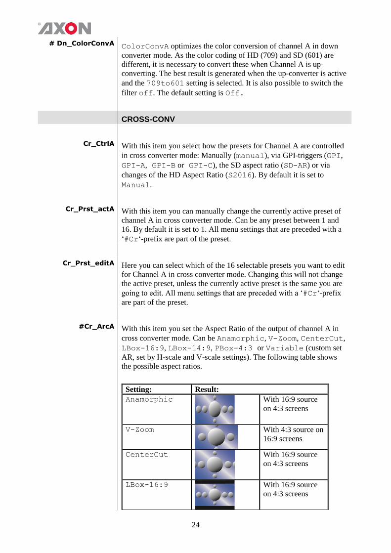
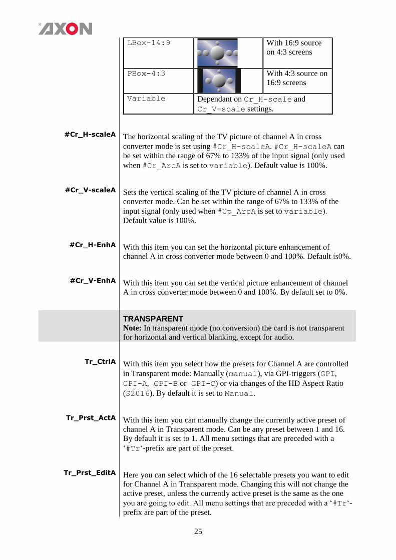
#Cr_ArcA With this item you set the Aspect Ratio of the output of channel A in
cross converter mode. Can be Anamorphic, V-Zoom, CenterCut,
LBox-16:9, LBox-14:9, PBox-4:3 or Variable (custom set
AR, set by H-scale and V-scale settings). The following table shows
the possible aspect ratios.
Setting: Result:
Anamorphic
With 16:9 source
on 4:3 screens
V-Zoom
With 4:3 source on
16:9 screens
CenterCut
With 16:9 source
on 4:3 screens
LBox-16:9
With 16:9 source
on 4:3 screens
25
LBox-14:9
With 16:9 source
on 4:3 screens
PBox-4:3
With 4:3 source on
16:9 screens
Variable Dependant on Cr_H-scale and
Cr_V-scale settings.
#Cr_H-scaleA The horizontal scaling of the TV picture of channel A in cross
converter mode is set using #Cr_H-scaleA. #Cr_H-scaleA can
be set within the range of 67% to 133% of the input signal (only used
when #Cr_ArcA is set to variable). Default value is 100%.
#Cr_V-scaleA Sets the vertical scaling of the TV picture of channel A in cross
converter mode. Can be set within the range of 67% to 133% of the
input signal (only used when #Up_ArcA is set to variable).
Default value is 100%.
#Cr_H-EnhA With this item you can set the horizontal picture enhancement of
channel A in cross converter mode between 0 and 100%. Default is0%.
#Cr_V-EnhA With this item you can set the vertical picture enhancement of channel
A in cross converter mode between 0 and 100%. By default set to 0%.
TRANSPARENT Note: In transparent mode (no conversion) the card is not transparent
for horizontal and vertical blanking, except for audio.
Tr_CtrlA With this item you select how the presets for Channel A are controlled
in Transparent mode: Manually (manual), via GPI-triggers (GPI,
GPI-A, GPI-B or GPI-C) or via changes of the HD Aspect Ratio
(S2016). By default it is set to Manual.
Tr_Prst_ActA With this item you can manually change the currently active preset of
channel A in Transparent mode. Can be any preset between 1 and 16.
By default it is set to 1. All menu settings that are preceded with a
‘#Tr‘-prefix are part of the preset.
Tr_Prst_EditA Here you can select which of the 16 selectable presets you want to edit
for Channel A in Transparent mode. Changing this will not change the
active preset, unless the currently active preset is the same as the one
you are going to edit. All menu settings that are preceded with a ‘#Tr‘-
prefix are part of the preset.
26
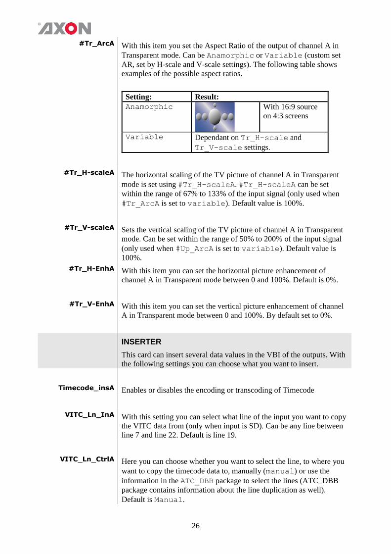
#Tr_ArcA With this item you set the Aspect Ratio of the output of channel A in
Transparent mode. Can be Anamorphic or Variable (custom set
AR, set by H-scale and V-scale settings). The following table shows
examples of the possible aspect ratios.
Setting: Result:
Anamorphic
With 16:9 source
on 4:3 screens
Variable Dependant on Tr_H-scale and
Tr_V-scale settings.
#Tr_H-scaleA The horizontal scaling of the TV picture of channel A in Transparent
mode is set using #Tr_H-scaleA. #Tr_H-scaleA can be set
within the range of 67% to 133% of the input signal (only used when
#Tr_ArcA is set to variable). Default value is 100%.
#Tr_V-scaleA Sets the vertical scaling of the TV picture of channel A in Transparent
mode. Can be set within the range of 50% to 200% of the input signal
(only used when #Up_ArcA is set to variable). Default value is
100%.
#Tr_H-EnhA With this item you can set the horizontal picture enhancement of
channel A in Transparent mode between 0 and 100%. Default is 0%.
#Tr_V-EnhA With this item you can set the vertical picture enhancement of channel
A in Transparent mode between 0 and 100%. By default set to 0%.
INSERTER
This card can insert several data values in the VBI of the outputs. With
the following settings you can choose what you want to insert.
Timecode_insA Enables or disables the encoding or transcoding of Timecode
VITC_Ln_InA With this setting you can select what line of the input you want to copy
the VITC data from (only when input is SD). Can be any line between
line 7 and line 22. Default is line 19.
VITC_Ln_CtrlA Here you can choose whether you want to select the line, to where you
want to copy the timecode data to, manually (manual) or use the
information in the ATC_DBB package to select the lines (ATC_DBB
package contains information about the line duplication as well).
Default is Manual.
27
VITC_Ln_625A When VITC_Ln_Ctrl is set to Manual, with this setting you can
select a line between 7 and 22 when the output is SD625. Default is
line 19.
VITC_Ln_525A When VITC_Ln_Ctrl is set to Manual, with this setting you can
select a line between 7 and 22 when the output is SD525. Default is
line 10.
VITC_Ln_DupA When set to On, the VITC line is duplicated to the above selected line
+ 2 lines.
ATC_Dem_SelA ATC source de-embed selection. Previously, the first ATC found in a
field would be transcoded to the output. Now, the user can select
whether to de-embed LTC, VITC or the first ATC found.
ATC_Emb_SelA ATC_Emb_Sel: ATC destination embed selection. Previously,
timecode was transcoded into VITC. Now the user can select whether
to transcode to VITC or LTC.
Ins_CtrlA With this item you select how the inserter presets for Channel A are
controlled: Manually (manual), via GPI-triggers (GPI, GPI-A, GPI-
B or GPI-C), via changes of the SD Aspect Ratio (SD_AR) or the HD
aspect ratio (S2016) (AFD)). Default is Manual.
Ins_Prst_ActA With this item you can manually change the currently active preset of
channel A when in transparent mode. Can be any preset between 1 and
16. By default it is set to 1. All menu settings that are preceded with a
‘#Ins’-prefix are part of the preset.
Ins_Prst_EditA Here you can select which of the 16 selectable presets you want to edit
for Channel A when in a transparent mode. Changing this will not
change the active preset, unless the currently active preset is the same
you are going to edit. All menu settings that are preceded with a
‘#Ins’-prefix are part of the preset.
#VI-InsertA You can turn VI insertion on or off for channel A. Default is Off.
#VI-DataA With the #VI-InsertA setting set to on, you can select VI values
with this setting, which you want to be inserted in Channel A. possible
are all VI values between 4:3_0 and 4:3_7 and the settings between
16:9_0 and 16:9_7. Default is 4:3_0.
28
#WSS-InsertA You can choose which type of WSS data you want to insert in Channel
A with this setting, or switch WSS insertion entirely off (default
value). You can set it to Standard or Extended.
#WSS-StndA With the #WSS-InsertA setting set to Standard, you can select
WSS standard values with this setting, which you want to be inserted in
Channel A. possible are all WSS values between 1_vid and 8_vid
and the settings between 1_flm and 8_flm. Default is 1_vid.
#WSS-ExtndA With the #VI-InsertA setting set to on, you can select VI values
with this setting, which you want to be inserted in Channel A. possible
are all WSS values between 4:3_0 and 4:3_7 and the settings
between 16:9_0 and 16:9_7. Default is 4:3_0.
#VI-DataA With the #WSS-InsertA setting set to extended, you can select
WSS extended values with this setting, which you want to be inserted
in Channel A. possible are all VI settings between 4:3_0 and 4:3_7
and the settings between 16:9_0 and 16:9_7. Default is 4:3_0.
#S2016-InsertA You can turn S2016 (AFD) insertion on or off for channel A. Default
is Off.
#S2016-LineA With this setting you select a line in the VBI to where the AFD
(SMPTE 2016) data should be written. Lines 0 till 31 are selectable. By
default it is set to line 17.
#S2016-DataA With thise setting you can select which AFD you want to insert.
Default is AFD0.
#CC_Ena_A This setting sets the Closed Captioning insertion for channel A On or
Off. Default is Off.
VIDEO PROC
GainA With this setting you control the overall gain of the video of channel A
between 50 and 150%. Default is 100%.
R-GainA R-GainA controls the Red gain of channel A. The control range is
between 50% and 150%. The default setting is 100%.
29
G-GainA G-GainA controls the Green gain of channel A. The control range is
between 50% and 150%. The default setting is 100%.
B-GainA B-GainA controls the Blue gain of channel A. The control range is
between 50% and 150%. The default setting is 100%.
BlackA BlackA controls the total R-G-B Black gain of channel A. The control
range is between –128bit and 127bit. The default setting is 0bit.
R-BlackA R-BlackA controls the Red-Black of channel A. The control range is
between –128bits and 127 bits in steps of 1 bit The
default setting is 0 bit.
G-BlackA G-BlackA controls the Green-Black of channel A. The control range
is between –128bits and 127 bits in steps of 1 bit The
default setting is 0 bit.
B-BlackA B-BlackA controls the Blue-Black of channel A. The control range is
between –128bits and 127 bits in steps of 1 bit The
default setting is 0 bit.
Note This function isn’t currently not accessible but will be enabled in a
software release in the future.
Y_Gain This function isn’t currently not accessible but will be enabled in a
software release in the future.
C_Gain This function isn’t currently not accessible but will be enabled in a
software release in the future.
EMBEDDER
Audio_CtrlA With this item you select how audio proc amp presets for Channel A
are controlled: Manually (Manual) or via GPI-triggers (GPI, GPI-A,
GPI-B or GPI-C). Default is Manual
Audio_Prst_ActA With this item you can manually change the currently active preset of
channel. Can be any preset between 1 and 16. By default it is set to 1.
All menu settings that are preceded with a ‘#Ins’-prefix are part of
the preset.
30
Audio_Prst_EditA Here you can select which of the 16 selectable presets you want to edit
for Channel A. Changing this will not change the active preset, unless
the currently active preset is the same you are going to edit. All menu
settings that are preceded with a ‘#Ins’-prefix are part of the preset.
#Silence-TimeA If the embedded audio contains silence, this can be reported by the
card. This setting allows you to determine how many seconds it takes
before the card reports the silence. This setting can be set in a range
from 1 sec to 255 sec. The default setting is 10sec.
#Silence-LevelA With this setting you set a loudness threshold for the silence detection.
Can be set between -100 and -20 dBFS. When the audio goes below
this value, a silence alert is triggered. Default is
-60dBFS.
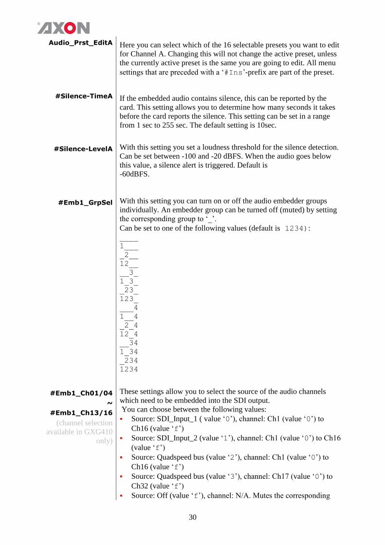
#Emb1_GrpSel With this setting you can turn on or off the audio embedder groups
individually. An embedder group can be turned off (muted) by setting
the corresponding group to ‘_’.
Can be set to one of the following values (default is 1234): ____
1___
_2__
12__
__3_
1_3_
_23_
123_
___4
1__4
_2_4
12_4
__34
1_34
_234
1234
#Emb1_Ch01/04
~
#Emb1_Ch13/16
(channel selection
available in GXG410
only)
These settings allow you to select the source of the audio channels
which need to be embedded into the SDI output.
You can choose between the following values:
Source: SDI_Input_1 ( value ‘0’), channel: Ch1 (value ‘0’) to
Ch16 (value ‘f’)
Source: SDI_Input_2 (value ‘1’), channel: Ch1 (value ‘0’) to Ch16
(value ‘f’)
Source: Quadspeed bus (value ‘2’), channel: Ch1 (value ‘0’) to
Ch16 (value ‘f’)
Source: Quadspeed bus (value ‘3’), channel: Ch17 (value ‘0’) to
Ch32 (value ‘f’)
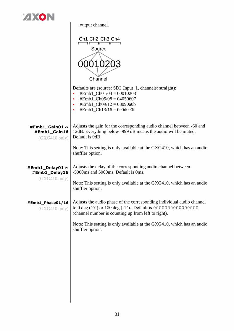
Source: Off (value ‘f’), channel: N/A. Mutes the corresponding
31
output channel.
00010203
Ch1
Source
Channel
Ch2 Ch3 Ch4
Defaults are (source: SDI_Input_1, channels: straight):
#Emb1_Ch01/04 = 00010203
#Emb1_Ch05/08 = 04050607
#Emb1_Ch09/12 = 08090a0b
#Emb1_Ch13/16 = 0c0d0e0f
#Emb1_Gain01 ~
#Emb1_Gain16
(GXG410 only)
Adjusts the gain for the corresponding audio channel between -60 and
12dB. Everything below -999 dB means the audio will be muted.
Default is 0dB
Note: This setting is only available at the GXG410, which has an audio
shuffler option.
#Emb1_Delay01 ~
#Emb1_Delay16
(GXG410 only)
Adjusts the delay of the corresponding audio channel between
-5000ms and 5000ms. Default is 0ms.
Note: This setting is only available at the GXG410, which has an audio
shuffler option.
#Emb1_Phase01/16
(GXG410 only)
Adjusts the audio phase of the corresponding individual audio channel
to 0 deg (‘0’) or 180 deg (‘1’). Default is 0000000000000000
(channel number is counting up from left to right).
Note: This setting is only available at the GXG410, which has an audio
shuffler option.
32
AUDIO PROC AMP
Audio-PhaseA If this setting is set to Align, the card ensures audio-phase alignment
between multiple audio channels and audio groups, which is necessary
for multi-channel (surround) purposes. If errors in the signal-chain
occur the de-embedder blocks reset synchronously to maintain audio-
phase-alignment.
If this setting is set to Off, the card does not ensure audio-phase
alignment and eats-all audio including errors. Even if there are
DBN/ANC/ECC or channel-sequence errors, the de-embedder will
pass them. Default is Align.
Note: This setting can be helpful to solve problems in the field using
equipment which doesn’t follow the standards correctly.
GPI-CTRL
This function isn’t currently not accessible but will be enabled in a
software release in the future.
NETWORK
IP_Conf0 With this setting you can let the card obtain an IP address
automatically via DHCP, or appoint a manual set IP address. By
default this setting is set to Manual.
mIP0 When IP_Conf0 is set to manual, you can type in the preferred IP
address here. By default it is set to 172.16.1.2
mNM0 With IP_Conf0 set to manual, with this setting you can set a
Netmask. Default is 255.255.0.0
mGW0 With IP_Conf0 set to manual, this setting let you set a Standard
Gateway. Default is set to 172.16.0.1
NetwPrefix0 Here you can set the proper network prefix if required.
33
6 Status Menu
Introduction The status menu indicates the current status of each item listed below.
SFP STATUS
SFP1-Vendor These status item display the name of the vendor of the SFP input/output
module A.
SFP1-Type These status items display the type name/number of SFP input/output
module A.
SFP1-Temp-Stat
These indicate whether the temperature of SFP input/output module A is
Too_High, High, OK, Low or Too_Low. Can also be NA in case
Temperature monitoring is not available or the module is not inserted.
SFP1-Volt-Stat
These indicate whether the voltage usage of SFP input/output module A
is Too_High, High, OK, Low or Too_Low. Can also be NA in case
Voltage monitoring is not available or the module is not inserted.
Port1/2-Enabled
These item indicate whether the corresponding output port on SFP output
module A is enabled, disabled or NA (Not available, when no
input signal is available or an input module is inserted.)
Port1/2-Power
These status items indicate the current transmitter power of the specified
port on SFP output module A between 0mW and 6.55mW. When a
receiver is installed or no SFP module is inserted this value is 0.
Port1/2-Power-
Stat
These indicate whether the output power of the specified port on SFP
output module A is Too_High, High, OK, Low or Too_Low. Can also
be NA in case of an input module or no module is inserted.
Port1/2-Bias
These status items indicate the current laser bias of the specified port on
SFP module A is between 0mA and 300mA. When there is a non fiber
SFP or an input module is inserted, this value will be 0.
Port1/2-Bias-Stat
These indicate whether the laser bias of the specified port on SFP output
module A is Too_High, High, OK, Low or Too_Low. This can also be
NA in case laser bias monitoring is not available or no output module is
inserted.
Port1/2-
Wavelength
Indicates the current wave length of the corresponding output port on the
SFP output module A between 0nm and 2000nm. When there is a non
fiber SFP or RX module installed, this value will be 0.
34
SFP2-Vendor These status item display the name of the vendor of the SFP input/output
module B.
SFP2-Type These status items display the type name/number of SFP input/output
module B.
SFP2-Temp-Stat
These indicate whether the above indicated temperature of SFP
input/output module B is Too_High, High, OK, Low or Too_Low.
This can also be NA in case Temperature monitoring is not available or
the module is not inserted.
SFP2-Volt-Stat
These indicate whether the above indicated voltage usage of SFP
input/output module B is Too_High, High, OK, Low or Too_Low.
This can also be NA in case Voltage monitoring is not available or the
module is not inserted.
Port3/4-Enabled
These item indicate whether the corresponding output on SFP output
module is enabled, disabled or NA (Not available, when no input
signal is available or an input module is inserted)
Port3/4-Power
These status items indicate the current transmitter power of the specified
port on SFP output module B between 0mW and 6.55mW. When an input
module is inserted or no SFP module is inserted this value is 0.
Port3/4-Power-
Stat
These indicate whether the output power of the specified port on SFP
output module B is Too_High, High, OK, Low or Too_Low. Can also
be NA in case of an input module or no module is inserted.
Port3/4-Bias
These status items indicate the current laser bias of the specified port on
SFP output module B is between 0mA and 300mA. When there is a non
fiber SFP or RX SFP installed, this value will be 0.
Port3/4-Bias-Stat
These indicate whether the laser bias of the specified port on SFP output
module B is Too_High, High, OK, Low or Too_Low. This can also be
NA in case laser bias monitoring is not available or no module is inserted.
Port3/4-
Wavelength
Indicates the current wave length of the corresponding output port on SFP
output module B between 0nm and 2000nm. When there is a non fiber
SFP or RX module installed, this value will be 0.
HDMI1-Vid-Std ~
HDMI2-Vid-Std These indicate the output format of each corresponding HDMI output.
Possible output formats are: ■ 1080p60, 1080p50
■ 1080i60, 1080i50
■ 1080p30, 1080p25, 1080p24
■ 720p60, 720p50, 720p30, 720p25, 720p24
■ SD625, SD525
35
HDMI1-GrpInUse ~
HDMI2-GrpInUse These status items indicate which the audio groups are in use on the
corresponding HDMI output. Indicated as for instance 1_3_ when
groups 1 and 3 are in use, and groups 2 and 4 are not; or for instance
as __34 when only groups 3 and 4 are in use and groups 1 and 2 are
not.
HDMI1-EDH-Stat ~
HDMI2-EDH-Stat These items indicate when EDH errors occur on the corresponding
HDMI output.
sInp1 ~ sInp2
This status item indicates the presence and the format of a valid signal
on physical input 1 to 8. This is displayed as: 1080P60
1080p50
1080i60
1080i50
1080p30
1080p25
1080p24
1080psf24
720p60
720p50
720p30
720p25
720p24
SD525
SD625
sInpA
This status item indicates the presence and the format of a valid signal
on processing channel. This is displayed the same as sInp1 ~ sInp2.
sInpA_VI
Displays the detected VI value found in processing channel A. This is
displayed as follows: 4:3_0
4:3_1
4:3_2
4:3_3
4:3_4
4:3_5
4:3_6
4:3_7
16:9_0
16:9_1
16:9_2
16:9_3
16:9_4
16:9_5
16:9_6
16:9_7
NA (no VI detected)
36
sInpA_WSS-Stnd
This status item displays the detected standard WSS value of
processing channel A. this is displayed as follows: 1_vid
2_vid
3_vid
4_vid
5_vid
6_vid
7_vid
8_vid
1_flm
2_flm
3_flm
4_flm
5_flm
6_flm
7_flm
8_flm
NA (no standard WSS detected)
sInpA_WSS-Extd This item displays the detected extended WSS value of processing
channel A. This is displayed as follows: 4:3_0
4:3_1
4:3_2
4:3_3
4:3_4
4:3_5
4:3_6
4:3_7
16:9_0
16:9_1
16:9_2
16:9_3
16:9_4
16:9_5
16:9_6
16:9_7
NA (no WSS extended detected)
sInpA_S2016
This item displays the detected SMPTE 2016 (AFD) values of
processing channel A. This is displayed as AFD0 till AFD15 or NA in
case no S2016 is detected.:
sInpA_CRC_EDH This item indicates CRC and EDH errors on processing channel A. Can
be: Off
OK
Error
NA
NoPCM

37
sInpA_Map This item indicates what the mapping of the signal is on processing
channel A. Can be: Level A
Level B
NA
sInpA_VITC This item indicates the presence of VITC in processing channelA. Can
be NA or OK.
sInpA_ATC This item indicates the presence of VITC in processing channelA. Can
be: RP188 LTC
RP188 VITC#1
RP188 VITC#2
RP196 LTC
RP196 VITC
RP215
NA
S2031-WST-DetA This item indicates the presence of S2031 packets which hold WST
information in processing channel A. Can be NA or OK.
S2031-OverflowA This status item indicates if there is a WST line number overflow of
channel A, when it exceeds the range from line 7 to line 22. This may
happen for a S2031 input source containing undefined WST lines
which are translated to a WST or OP47 output. An overflow will occur
for instance when setting S2031-WST-defA to line 22 and several
WST lines are to follow. Then the value of this status item will be
Error. Can be NA, OK or Error.
S2031-WST-LineA This status item indicates the type of WST lines which are packetized
by S2031. It will display Error, when containing both undefined and
defined lines. Can be: NA
Defined
Undefined
Error
WST-DetA This item indicates the presence of WST information in processing
channel A. Can be NA or OK.
OP47-Det-A This item indicates the presence of OP47 packets in processing channel
A. Can be NA or OK
CC_Det_A Displays whether or not there’s Closed Captioning detected on channel
A
38
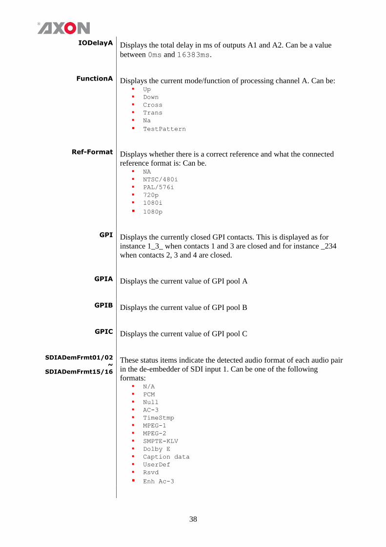
IODelayA Displays the total delay in ms of outputs A1 and A2. Can be a value
between 0ms and 16383ms.
FunctionA Displays the current mode/function of processing channel A. Can be: Up
Down
Cross
Trans
Na
TestPattern
Ref-Format Displays whether there is a correct reference and what the connected
reference format is: Can be. NA
NTSC/480i
PAL/576i
720p
1080i
1080p
GPI Displays the currently closed GPI contacts. This is displayed as for
instance 1_3_ when contacts 1 and 3 are closed and for instance _234
when contacts 2, 3 and 4 are closed.
GPIA Displays the current value of GPI pool A
GPIB Displays the current value of GPI pool B
GPIC Displays the current value of GPI pool C
SDIADemFrmt01/02 ~
SDIADemFrmt15/16
These status items indicate the detected audio format of each audio pair
in the de-embedder of SDI input 1. Can be one of the following
formats: N/A
PCM
Null
AC-3
TimeStmp
MPEG-1
MPEG-2
SMPTE-KLV
Dolby E
Caption data
UserDef
Rsvd
Enh Ac-3
39
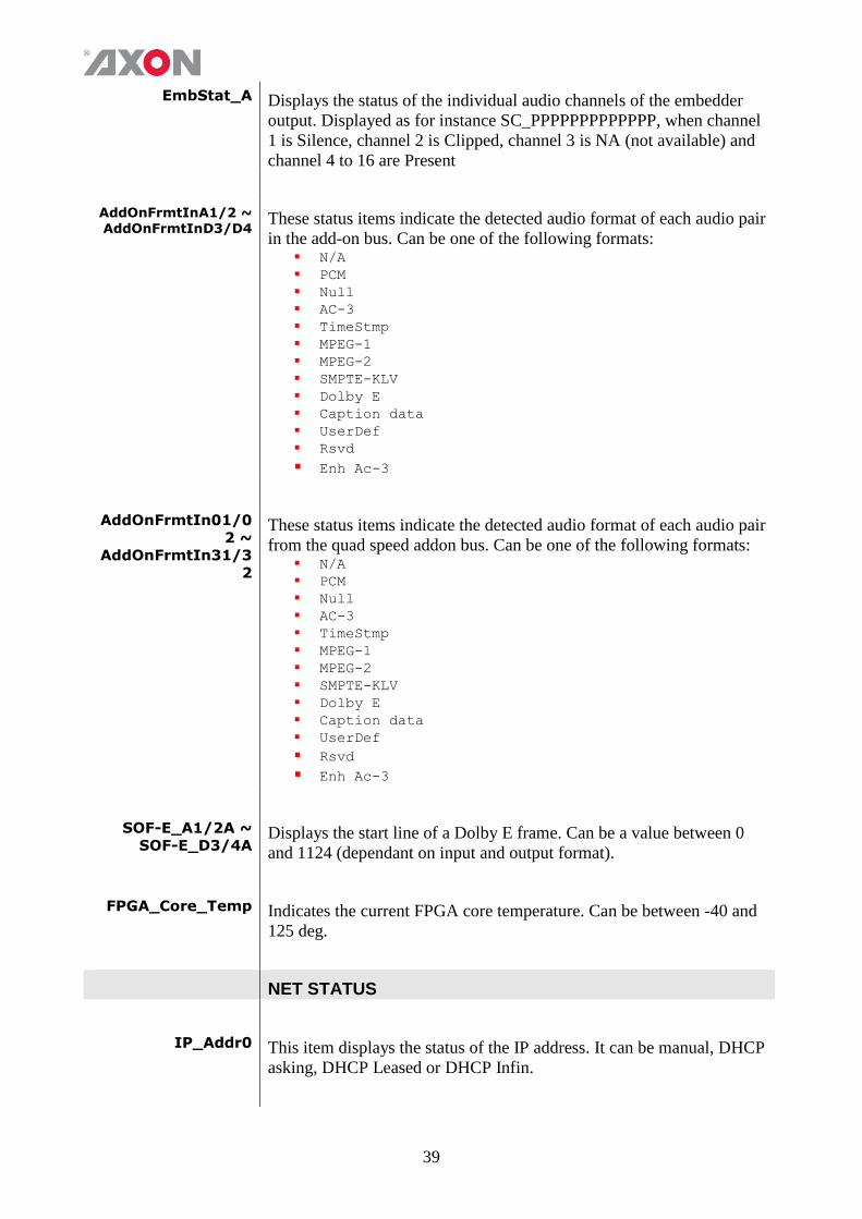
EmbStat_A Displays the status of the individual audio channels of the embedder
output. Displayed as for instance SC_PPPPPPPPPPPPP, when channel
1 is Silence, channel 2 is Clipped, channel 3 is NA (not available) and
channel 4 to 16 are Present
AddOnFrmtInA1/2 ~ AddOnFrmtInD3/D4
These status items indicate the detected audio format of each audio pair
in the add-on bus. Can be one of the following formats: N/A
PCM
Null
AC-3
TimeStmp
MPEG-1
MPEG-2
SMPTE-KLV
Dolby E
Caption data
UserDef
Rsvd
Enh Ac-3
AddOnFrmtIn01/0
2 ~
AddOnFrmtIn31/3
2
These status items indicate the detected audio format of each audio pair
from the quad speed addon bus. Can be one of the following formats: N/A
PCM
Null
AC-3
TimeStmp
MPEG-1
MPEG-2
SMPTE-KLV
Dolby E
Caption data
UserDef
Rsvd
Enh Ac-3
SOF-E_A1/2A ~
SOF-E_D3/4A Displays the start line of a Dolby E frame. Can be a value between 0
and 1124 (dependant on input and output format).
FPGA_Core_Temp Indicates the current FPGA core temperature. Can be between -40 and
125 deg.
NET STATUS
IP_Addr0 This item displays the status of the IP address. It can be manual, DHCP
asking, DHCP Leased or DHCP Infin.

40
MAC0 This item displays the MAC address of the card.
IP0 This item displays the current IP address of the card.
NM0 This item displays the current Netmask of the card.
GW0 This item displays the current Standard Gateway of the card.
41
7 Events Menu
Introduction An event is a special message that is generated on the card asynchronously.
This means that it is not the response to a request to the card, but a
spontaneous message.
What is the Goal of
an event? The goal of events is to inform the environment about a changing condition
on the card. A message may be broadcast to mark the change in status. The
message is volatile and cannot be retrieved from the system after it has been
broadcast. There are several means by which the message can be filtered.
Events The events reported by the GXG-HXH400-410 are as follows;
Announcements Announcements is not an event. This item is only used for switching the
announcement of status changes on/off. 0=off, other =on
Input_A Input_A can be selected between 0 .. 255. 0= no event, 1..255 is the priority
setting.
Input_B Input_B can be selected between 0 .. 255. 0= no event, 1..255 is the priority
setting.
Ref-Status Reference can be selected between 0 .. 255. 0= no event, 1..255 is the
priority setting.
Active_Out_A Active output A can be selected between 0 .. 255. 0= no event, 1..255 is the
priority setting.
What information
is available in an
event?
The message consists of the following items;
1) A message string to show what has happened in text, for example:
“INP_LOSS”, “REF_LOSS”, “INP_RETURN”.
2) A tag that also shows what happens, but with a predefined number: e.g.
1 (= loss of input), 2 (= loss of reference), 129(= 1+128 = return of
input). For a list of these predefined tags see the table on the next page.
3) A priority that marks the importance of an event. This value is defined
by the user and can have any value between 1 and 255, or 0 when
disabled.
4) A slot number of the source of this event.
The Message String The message string is defined in the card and is therefore fixed. It may be
used in controlling software like Synapse Set-up to show the event.
42
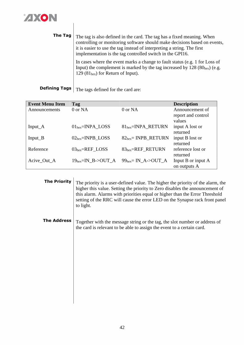
The Tag The tag is also defined in the card. The tag has a fixed meaning. When
controlling or monitoring software should make decisions based on events,
it is easier to use the tag instead of interpreting a string. The first
implementation is the tag controlled switch in the GPI16.
In cases where the event marks a change to fault status (e.g. 1 for Loss of
Input) the complement is marked by the tag increased by 128 (80hex) (e.g.
129 (81hex) for Return of Input).
Defining Tags The tags defined for the card are:
Event Menu Item Tag Description
Announcements 0 or NA 0 or NA Announcement of
report and control
values
Input_A 01hex=INPA_LOSS 81hex=INPA_RETURN input A lost or
returned
Input_B 02hex=INPB_LOSS 82hex= INPB_RETURN input B lost or
returned
Reference 03hex=REF_LOSS 83hex=REF_RETURN reference lost or
returned
Acive_Out_A 19hex=IN_B->OUT_A 99hex= IN_A->OUT_A Input B or input A
on outputs A
The Priority The priority is a user-defined value. The higher the priority of the alarm, the
higher this value. Setting the priority to Zero disables the announcement of
this alarm. Alarms with priorities equal or higher than the Error Threshold
setting of the RRC will cause the error LED on the Synapse rack front panel
to light.
The Address Together with the message string or the tag, the slot number or address of
the card is relevant to be able to assign the event to a certain card.
43
8 LED Indication
Error LED The error LED indicates an error if the internal logic of the card is not
configured correctly or has a hardware failure.
Input_x LED This LED indicated the presence of a valid SDI video signal on input x.
ANC Data LED Indicates the presence of embedded audio within the input signal.
Reference LED Indicated the presence of a valid reference signal on the selected
reference input connector (ref-1 or ref-2).
Data Error LED This LED indicates a CRC error.
Connection LED This LED illuminates after the card has initialized. The LED lights for
0.5 seconds every time a connection is made to the card.
44
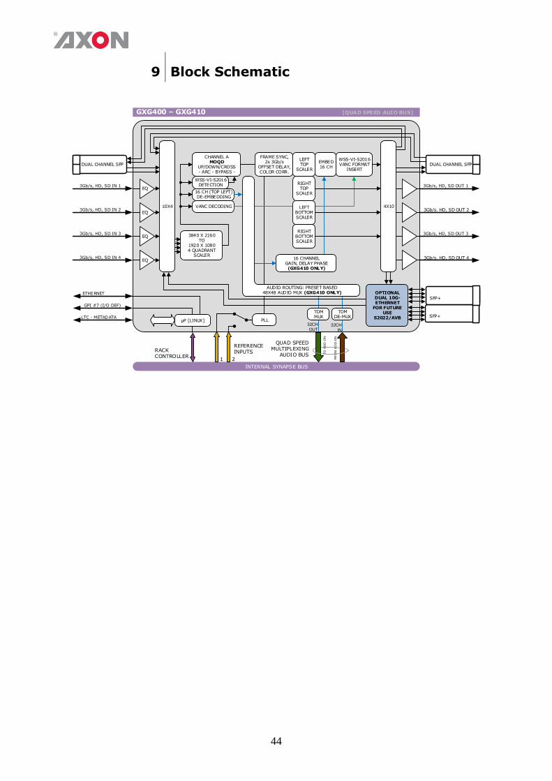
9 Block Schematic
INTERNAL SYNAPSE BUS
GXG400 – GXG410 [QUAD SPEED AUIO BUS]
RACK CONTROLLER
REFERENCEINPUTS
1 2
µP [LINUX]
CHANNEL AMOQD
UP/DOWN/CROSS- ARC - BYPASS -
PLL
WSS-VI-S2016DETECTION
EQ
EQ
3Gb/s. HD, SD OUT 2
3Gb/s, HD, SD OUT 4
DUAL CHANNEL SFP
4X10
16 CH (TOP LEFT) DE-EMBEDDING
EMBED16 CH
WSS-VI-S2016VANC FORMAT
INSERT
16 CHANNELGAIN, DELAY PHASE(GXG410 ONLY)
QUAD SPEED MULTIPLEXING
AUDIO BUS
32CHOUT
32CHIN
TO
AD
D-O
N
FR
OM
AD
D-O
N
FRAME SYNC,2s 3Gb/s
OFFSET DELAY,COLOR CORR.
LEFT TOP
SCALER
TDMMUX
TDMDE-MUX
DUAL CHANNEL SFP
VANC DECODING
AUDIO ROUTING: PRESET BASED48X48 AUDIO MUX (GXG410 ONLY)
SFP+
EQ
EQ
OPTIONAL DUAL 10G-ETHERNET
FOR FUTURE USE
S2022/AVB
RIGHT TOP
SCALER
LEFT BOTTOM SCALER
RIGHT BOTTOM SCALER
10X4
3840 X 2160TO
1920 X 10804 QUADRANT
SCALER
SFP+
45
10 Connector Panels
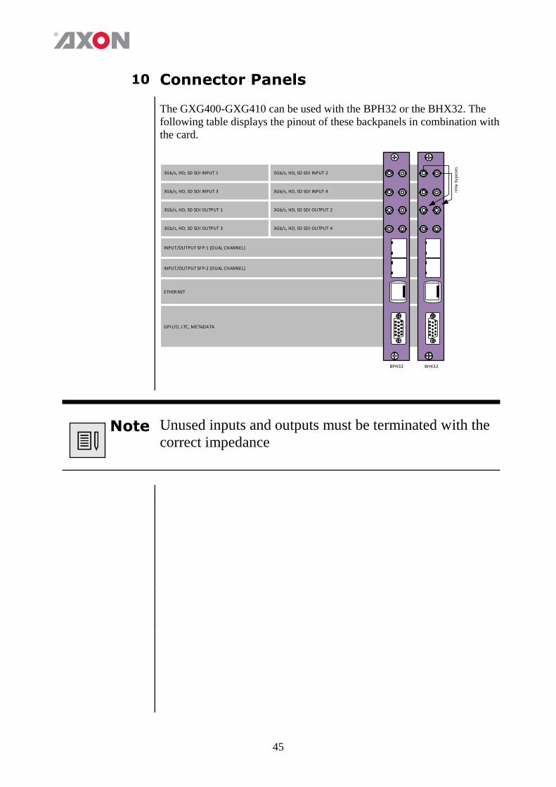
The GXG400-GXG410 can be used with the BPH32 or the BHX32. The
following table displays the pinout of these backpanels in combination with
the card.
3Gb/s, HD, SD SDI OUTPUT 2
3Gb/s, HD, SD SDI INPUT 4
3Gb/s, HD, SD SDI INPUT 2
3Gb/s, HD, SD SDI OUTPUT 4
ETHER NET
INPUT/OUTPUT SFP-2 (DUAL CHANNEL)
INPUT/OUTPUT SFP-1 (DUAL CHANNEL)
3Gb/s, HD, SD SDI OUTPUT 3
GPI I/O, LTC, METADATA
BPH32
rela
y b
yp
ass
es
BHX32
3Gb/s, HD, SD SDI OUTPUT 1
3Gb/s, HD, SD SDI INPUT 3
3Gb/s, HD, SD SDI INPUT 1
Note Unused inputs and outputs must be terminated with the
correct impedance

46
Appendix 1 GPI Interface
This function isn’t currently not accessible but will be enabled in a software
release in the future.
47
Appendix 2 Reprogramming GXGxxx modules
Before you start
Functionality
explanation
A Synapse card’s functionality is decided by 2 parts: the hardware
platform and the software (a.k.a. firmware) that resides on the
hardware platform. Changing the firmware of the cards means
changing the way the card functions. To keep improving quality and
to answer our customer’s demands, Axon sometimes releases new
software revisions of Synapse cards. These software revisions are
formatted in 1 file per revision, with a .spf extension. Customers can
download these .spf files from our website, or receive them via e-mail
from our support so they can upgrade or reprogram their own cards.
Choosing .spf files Not all .spf files are compatible with all hardware platforms. To know
for certain that you are choosing a compatible .spf file you have to
know the hardware revision of your card. This revision number can be
found in the menu of the card via the control panel on the frames
(select card, select ‘about’, check HW number) or via Cortex (Axon’s
control software) (select frame, select card, select ‘Identity’, check
‘hardware rev’).
Knowing the hardware revision number, you can go to our website
(www.axon.tv) and go to our download firmware section. Here you
select the card you wish to upgrade. You will see a list of available
firmware upgrades of this particular card. The firmware files that are
compatible with your card should display your card’s hardware
revision number in table next to “Hardware versions”. If this is not
the case you will not be able to upgrade your card with that file.
Requirements For reprogramming or upgrading cards, you need the Cortex program
installed on a PC or laptop which is connected to the same network to
which the card is connected also. You can download the program free
of charge from our website. For this this card you need to use Cortex
version v1.091 or later. Updating the card must be done locally (direct
connection) through the Ethernet of the backplane. The bottom
Ethernet connection must be used.
Using Cortex help
files
This manual describes how to upgrade cards using Cortex. When you
are using Cortex and require card further instructions, please refer to
the Cortex help files (select ‘Card’ in the menu > select ‘Upload
Firmware’ (the firmware uploading window will open) > press F1).
48
Precautions
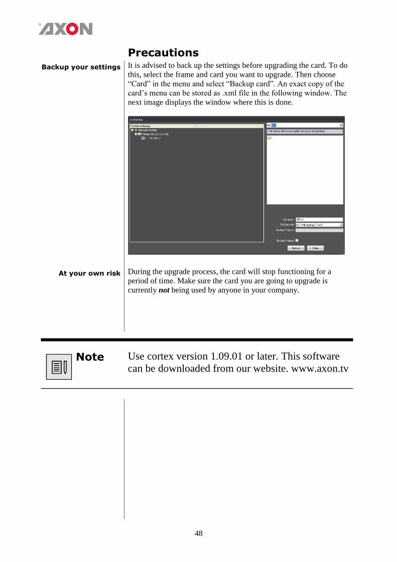
Backup your settings It is advised to back up the settings before upgrading the card. To do
this, select the frame and card you want to upgrade. Then choose
“Card” in the menu and select “Backup card”. An exact copy of the
card’s menu can be stored as .xml file in the following window. The
next image displays the window where this is done.
At your own risk During the upgrade process, the card will stop functioning for a
period of time. Make sure the card you are going to upgrade is
currently not being used by anyone in your company.
Note Use cortex version 1.09.01 or later. This software
can be downloaded from our website. www.axon.tv
49
Setting up card To be able to program the card direct we need to perform two steps.
One is setting up of the IP address of the card and second will be
making the board recognized as stand alone entity.
To set-up the IP address of the card goto the system view within the
Cortex program. Select the HLDxxx and goto the device view tab.
Within the device tab you will be able to setup the IP address,
netmask and gateway.
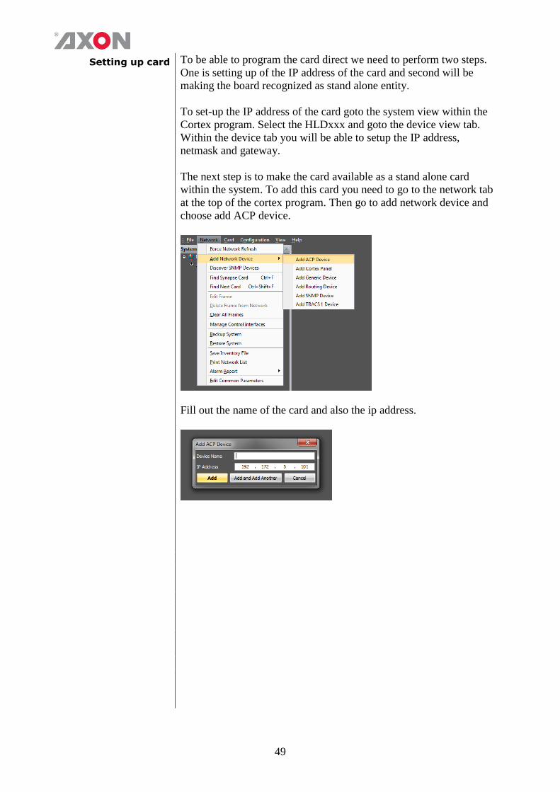
The next step is to make the card available as a stand alone card
within the system. To add this card you need to go to the network tab
at the top of the cortex program. Then go to add network device and
choose add ACP device.
Fill out the name of the card and also the ip address.
50
Upload firmware
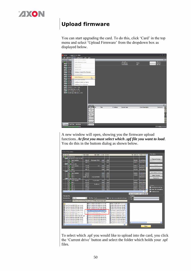
You can start upgrading the card. To do this, click ‘Card’ in the top
menu and select ‘Upload Firmware’ from the dropdown box as
displayed below.
A new window will open, showing you the firmware upload
functions. At first you must select which .spf file you want to load.
You do this in the buttom dialog as shown below.
To select which .spf you would like to upload into the card, you click
the ‘Current drive’ button and select the folder which holds your .spf
files.
51
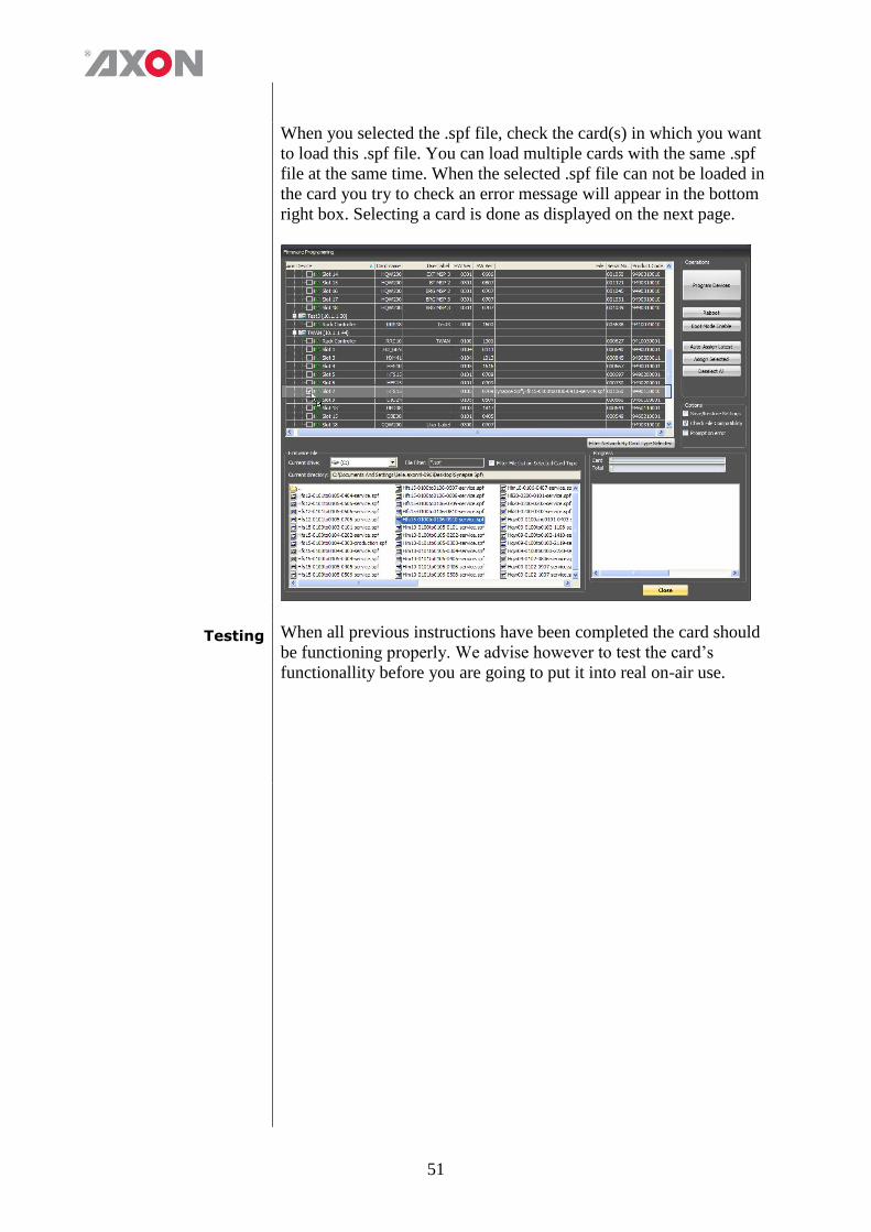
When you selected the .spf file, check the card(s) in which you want
to load this .spf file. You can load multiple cards with the same .spf
file at the same time. When the selected .spf file can not be loaded in
the card you try to check an error message will appear in the bottom
right box. Selecting a card is done as displayed on the next page.
Testing When all previous instructions have been completed the card should
be functioning properly. We advise however to test the card’s
functionallity before you are going to put it into real on-air use.
52
This product contains open-source software This product contains open-source software licensed under the GNU Public License (GPL). A copy of the GNU Public License is included below. Under this license you are eligible to receive a copy of the source code of this software including any changes. Axon Digital Design shall provide the source code on request either through physical distribution or electronic communication. For physical distribution you may be charged a fee that covers distribution costs. This offer is valid up to three years after date of purchase. Please direct your request to the support department of Axon Digital Design. Axon Digital Design supports open-source software by participating in the development of open-source projects or submitting improvements to these projects. For more information see http://opensource.axon.tv/
GNU Public License version 2 TERMS AND CONDITIONS FOR COPYING, DISTRIBUTION AND MODIFICATION 0. This License applies to any program or other work which contains a notice placed by the copyright holder saying it may be distributed under the terms of this General Public License. The “Program”, below, refers to any such program or work, and a “work based on the Program” means either the Program or any derivative work under copyright law: that is to say, a work containing the Program or a portion of it, either verbatim or with modifi cations and/or translated into another language. (Hereinafter, translation is included without limitation in the term “modifi cation”.) Each licensee is addressed as “you”. Activities other than copying, distribution and modifi cation are not covered by this License; they are outside its scope. The act of running the Program is not restricted, and the output from the Program is covered only if its contents constitute a work based on the Program (independent of having been made by running the Program). Whether that is true depends on what the Program does. 1. You may copy and distribute verbatim copies of the Program’s source code as you receive it, in any medium, provided that you conspicuously and appropriately publish on each copy an appropriate copyright notice and disclaimer of warranty; keep intact all the notices that refer to this License and to the absence of any warranty; and give any other recipients of the Program a copy of this License along with the Program. You may charge a fee for the physical act of transferring a copy, and you may at your option offer warranty protection in exchange for a fee. 2. You may modify your copy or copies of the Program or any portion of it, thus forming a work based on the Program, and copy and distribute such modifications or work under the terms of Section 1 above, provided that you also meet all of these conditions:
a) You must cause the modified files to carry prominent notices stating that you changed the fi les and the date of any change. b) You must cause any work that you distribute or publish, that in whole or in part contains or is derived from the Program or any
part thereof, to be licensed as a whole at no charge to all third parties under the terms of this License. c) If the modified program normally reads commands interactively when run, you must cause it, when started running for such
interactive use in the most ordinary way, to print or display an announcement including an appropriate copyright notice and a notice that there is no warranty (or else, saying that you provide a warranty) and that users may redistribute the program under these conditions, and telling the user how to view a copy of this License. (Exception: if the Program itself is interactive but does not normally print such an announcement, your work based on the Program is not required to print an announcement.)
These requirements apply to the modified work as a whole. If identifiable sections of that work are not derived from the Program, and can be reasonably considered independent and separate works in themselves, then this License, and its terms, do not apply to those sections when you distribute them as separate works. But when you distribute the same sections as part of a whole which is a work based on the Program, the distribution of the whole must be on the terms of this License, whose permissions for other licensees extend to the entire whole, and thus to each and every part regardless of who wrote it. Thus, it is not the intent of this section to claim rights or contest your rights to work written entirely by you; rather, the intent is to exercise the right to control the distribution of derivative or collective works based on the Program. In addition, mere aggregation of another work not based on the Program with the Program (or with a work based on the Program) on a volume of a storage or distribution medium does not bring the other work under the scope of this License. 3. You may copy and distribute the Program (or a work based on it, under Section 2) in object code or executable form under the terms of Sections 1 and 2 above provided that you also do one of the following:
a) Accompany it with the complete corresponding machine-readable source code, which must be distributed under the terms of Sections 1 and 2 above on a medium customarily used for software interchange; or,
b) Accompany it with a written offer, valid for at least three years, to give any third party, for a charge no more than your cost of physically performing source distribution, a complete machine-readable copy of the corresponding source code, to be distributed under the terms of Sections 1 and 2 above on a medium customarily used for software interchange; or,
53
c) Accompany it with the information you received as to the offer to distribute corresponding source code. (This alternative is allowed only for noncommercial distribution and only if you received the program in objects code or executable form with such an offer, in accord with Subsection b above.)
The source code for a work means the preferred form of the work for making modifi cations to it. For an executable work, complete source code means all the source code for all modules it contains, plus any associated interface defi nition fi les, plus the scripts used to control compilation and installation of the executable. However, as a special exception, the source code distributed need not include anything that is normally distributed (in either source or binary form) with the major components (compiler, kernel, and so on) of the operating system on which the executable runs, unless that component itself accompanies the executable. If distribution of executable or object code is made by offering access to copy from a designated place, then offering equivalent access to copy the source code from the same place counts as distribution of the source code, even though third parties are not compelled to copy the source along with the object code. 4. You may not copy, modify, sublicense, or distribute the Program except as expressly provided under this License. Any attempt otherwise to copy, modify, sublicense or distribute the Program is void, and will automatically terminate your rights under this License. However, parties who have received copies, or rights, from you under this License will not have their licenses terminated so long as such parties remain in full compliance. 5. You are not required to accept this License, since you have not signed it. However, nothing else grants you permission to modify or distribute the Program or its derivative works. These actions are prohibited by law if you do not accept this License. Therefore, by modifying or distributing the Program (or any work based on the Program), you indicate your acceptance of this License to do so, and all its terms and conditions for copying, distributing or modifying the Program or works based on it. 6. Each time you redistribute the Program (or any work based on the Program), the recipient automatically receives a license from the original licensor to copy, distribute or modify the Program subject to these terms and conditions. You may not impose any further restrictions on the recipients’ exercise of the rights granted herein. You are not responsible for enforcing compliance by third parties to this License. 7. If, as a consequence of a court judgment or allegation of patent infringement or for any other reason (not limited to patent issues), conditions are imposed on you (whether by court order, agreement or otherwise) that contradict the conditions of this License, they do not excuse you from the conditions of this License. If you cannot distribute so as to satisfy simultaneously your obligations under this License and any other pertinent obligations, then as a consequence you may not distribute the Program at all. For example, if a patent license would not permit royalty-free redistribution of the Program by all those who receive copies directly or indirectly through you, then the only way you could satisfy both it and this License would be to refrain entirely from distribution of the Program. If any portion of this section is held invalid or unenforceable under any particular circumstance, the balance of the section is intended to apply and the section as a whole is intended to apply in other circumstances. It is not the purpose of this section to induce you to infringe any patents or other property right claims or to contest validity of any such claims; this section has the sole purpose of protecting the integrity of the free software distribution system, which is implemented by public license practices. Many people have made generous contributions to the wide range of software distributed through that system in reliance on consistent application of that system; it is up to the author/donor to decide if he or she is willing to distribute software through any other system and a licensee cannot impose that choice. This section is intended to make thoroughly clear what is believed to be a consequence of the rest of this License. 8. If the distribution and/or use of the Program is restricted in certain countries either by patents or by copyrighted interfaces, the original copyright holder who places the Program under this License may add an explicit geographical distribution limitation excluding those countries, so that distribution is permitted only in or among countries not thus excluded. In such case, this License incorporates the limitation as if written in the body of this License. 9. The Free Software Foundation may publish revised and/or new versions of the General Public License from time to time. Such new versions will be similar in spirit to the present version, but may differ in detail to address new problems or concerns. Each version is given a distinguishing version number. If the Program specifies a version number of this License which applies to it and “any later version”, you have the option of following the terms and conditions either of that version or of any later version published by the Free Software Foundation. If the Program does not specify a version number of this License, you may choose any version ever published by the Free Software Foundation. 10. If you wish to incorporate parts of the Program into other free programs whose distribution conditions are different, write to the author to ask for permission. For software which is copyrighted by the Free Software Foundation, write to the Free Software Foundation; we sometimes make exceptions for this. Our decision will be guided by the two goals of preserving the free status of all derivatives of our free software and of promoting the sharing and reuse of software generally.

54
NO WARRANTY 11. BECAUSE THE PROGRAM IS LICENSED FREE OF CHARGE, THERE IS NO WARRANTY FOR THE PROGRAM, TO THE EXTENT PERMITTED BY APPLICABLE LAW. EXCEPT WHEN OTHERWISE STATED IN WRITING THE COPYRIGHT HOLDERS AND/OR OTHER PARTIES PROVIDE THE PROGRAM “AS IS” WITHOUT WARRANTY OF ANY KIND, EITHER EXPRESSED OR IMPLIED, INCLUDING, BUT NOT LIMITED TO, THE IMPLIED WARRANTIES OF MERCHANTABILITY AND FITNESS FOR A PARTICULAR PURPOSE. THE ENTIRE RISK AS TO THE QUALITY AND PERFORMANCE OF THE PROGRAM IS WITH YOU. SHOULD THE PROGRAM PROVE DEFECTIVE, YOU ASSUME THE COST OF ALL NECESSARY SERVICING, REPAIR OR CORRECTION. 12. IN NO EVENT UNLESS REQUIRED BY APPLICABLE LAW OR AGREED TO IN WRITING WILL ANY COPYRIGHT HOLDER, OR ANY OTHER PARTY WHO MAY MODIFY AND/OR REDISTRIBUTE THE PROGRAM AS PERMITTED ABOVE, BE LIABLE TO YOU FOR DAMAGES, INCLUDING ANY GENERAL, SPECIAL, INCIDENTAL OR CONSEQUENTIAL DAMAGES ARISING OUT OF THE USE OR INABILITY TO USE THE PROGRAM (INCLUDING BUT NOT LIMITED TO LOSS OF DATA OR DATA BEING RENDERED INACCURATE OR LOSSES SUSTAINED BY YOU OR THIRD PARTIES OR A FAILURE OF THE PROGRAM TO OPERATE WITH ANY OTHER PROGRAMS), EVEN IF SUCH HOLDER OR OTHER PARTY HAS BEEN ADVISED OF THE POSSIBILITY OF SUCH DAMAGES.