Embed Size (px)
Citation preview
Neptune Energy Netherlands B.V.
Specification 502 rev. 18 Page 2 of 37
TABLE OF CONTENTS
1.0 SCOPE ............................................................................................................................................... 4
2.0 CODES, STANDARDS AND SPECIFICATIONS.............................................................................. 5
3.0 PIPING FABRICATION .................................................................................................................... 7
3.1 GENERAL ........................................................................................................................................................... 7 3.2 DRAWINGS ....................................................................................................................................................... 7 3.3 PRE-FABRICATION ......................................................................................................................................... 8 3.4 WELDING CARBON STEEL .......................................................................................................................... 8 3.4.1 General .......................................................................................................................................................... 8 3.4.2 Welding Procedure Specifications WPS........................................................................................... 8 3.4.3 Welding Procedure Qualification ....................................................................................................... 9 3.4.4 Welders Competence ............................................................................................................................ 10 3.4.5 Welding preparation ............................................................................................................................. 10 3.4.6 Earthing ....................................................................................................................................................... 10 3.4.7 Welding Consumables .......................................................................................................................... 10 3.4.6 Weld numbering ..................................................................................................................................... 11 3.4.7 Production welding ................................................................................................................................ 11 3.4.8 Repairs ......................................................................................................................................................... 12 3.4.9 Post Weld Heat Treatment (PWHT) ................................................................................................. 12 3.4.10 Golden Weld ............................................................................................................................................. 12 3.5 PIPE SUPPORT FABRICATION AND INSTALLATION ....................................................................... 12
4.0 PIPING INSTALLATION ................................................................................................................ 13
4.1 REMARKS FOR PIPING INSTALLATION ............................................................................................... 13 4.2 FLANGE JOINTING AND BOLTING ........................................................................................................ 15 4.2.1 Scope ........................................................................................................................................................... 16 4.2.2 Codes ........................................................................................................................................................... 16 4.2.3 Bolting-up Requirements and selection of tools ....................................................................... 16 4.2.4 Flange Inspection and Preparation .................................................................................................. 18 4.2.5 Gasket / ring Inspection and Preparation ..................................................................................... 18 4.2.6 Stud / nut inspection and preparation ........................................................................................... 20 4.2.7 Installation Procedure - Tensioning ................................................................................................ 20 4.2.8 Tools ............................................................................................................................................................. 21 4.2.9 Bolt-up Sequence ................................................................................................................................... 22 4.3 THREADED CONNECTIONS ..................................................................................................................... 23 4.3.1 Guidelines for the making of small-bore NPT connections ................................................... 23 4.3.2 Material problems in making threaded connections ............................................................... 24 4.3.3 Galvanic corrosion and threaded connections ........................................................................... 25
5.0 REQUIREMENTS FOR NON CARBON STEEL AND GALVANISED PIPING .............................. 25
5.1 REQUIREMENTS FOR DUPLEX STEEL, SUPER DUPLEX STEEL (CLASS … DS) AND
STAINLESS (S) .............................................................................................................................................................. 25 5.1.1 Handling Duplex steel (See Attachment I to this specification) and Stainless Steel. ... 25 5.1.2 Welding of Duplex steel and Stainless (316L) ............................................................................. 25 5.1.3 Pickling and passivating of Duplex steel and Stainless (316L).............................................. 25 5.2 REQUIREMENTS FOR CUNIFER PIPING (CLASS 15UK) .................................................................. 25 5.2.1 General ........................................................................................................................................................ 26 5.2.2 Handling ..................................................................................................................................................... 26 5.2.3 Welding ...................................................................................................................................................... 26
Neptune Energy Netherlands B.V.
Specification 502 rev. 18 Page 3 of 37
5.3 REQUIREMENTS FOR POLY ETHYLENE PIPING (CLASS 15UP) ................................................... 26 5.4 REQUIREMENTS FOR HOT DIP GALVANISED PIPING (CLASS 15U) ......................................... 27 5.5 CLASS U2 ......................................................................................................................................................... 27 5.5 SYSTEMS THAT REQUIRE EXTRA GRADE OF CLEANING .............................................................. 28
6.0 FLUSHING AND PRESSURE TESTING ......................................................................................... 29
6.1 SCOPE ............................................................................................................................................................... 29 6.2 FLUSHING ....................................................................................................................................................... 29 6.2.1 Systems that require extra grade of cleaning. ............................................................................ 29 6.2.2 Systems to be cleaned as hydraulic control piping................................................................. 29 6.3 TESTING AND TEST SYSTEMS ................................................................................................................. 30 6.3.1 Procedure Onshore ................................................................................................................................ 30 6.3.2 Medium ...................................................................................................................................................... 32 6.3.3 Testing and recording ........................................................................................................................... 33 6.3.4 Preparation system after testing ...................................................................................................... 34 6.3.5 Alternative methods .............................................................................................................................. 34 6.3.6 Inspection and witnessing ................................................................................................................... 34 6.4 SAFETY DURING PRESSURE TESTING .................................................................................................. 34
7.0 QC PIPING FABRICATION ............................................................................................................ 35
7.1 GENERAL ......................................................................................................................................................... 35 7.2 INSPECTION PIPING PREFABRICATION .............................................................................................. 35 7.2.1 Preparation for coating ........................................................................................................................ 35 7.3 INSPECTION PIPING INSTALLATION .................................................................................................... 35 7.4 NON DESTRUCTIVE TESTING .................................................................................................................. 36 7.4.1 Quantities ................................................................................................................................................... 36 7.4.2 Types and standards for NDT ............................................................................................................ 36
8.0 DOCUMENTATION ....................................................................................................................... 37
9.0 DELIVERY AND TRANSPORT ....................................................................................................... 37
10.0 ATTACHMENTS ............................................................................................................................. 37
Neptune Energy Netherlands B.V.
Specification 502 rev. 18 Page 4 of 37
1.0 SCOPE
This specification is intended to supplement and confirm good working practice during
fabrication, assembly and erection of piping onshore and offshore.
The fabrication and assembly shall be in accordance with industry codes, specifications and
"Approved for Construction Drawings".
All piping shall be designed, fabricated and inspected per subject General Specifications and
according to PED and NEN-EN 13480 for platform piping and in accordance with NEN 3650
for transport pipelines (requirements for pipeline systems) and NEN 3656 Requirements for
submarine pipeline systems in steel).
Neptune Energy Netherlands B.V.
Specification 502 rev. 18 Page 5 of 37
2.0 CODES, STANDARDS AND SPECIFICATIONS
All piping shall be designed, fabricated and inspected per subject General Specifications and
according to Pressure Equipment Directive (PED) and/or NEN 3650 & NEN 3656.
If piping is actually subject to authorisation per PED:
this will be clearly indicated on the "Approved for Construction drawings",
all required fabrication and testing approvals for subject piping shall be obtained.
If piping is actually subject to authorisation per NEN 3650 or NEN 3656:
this will be clearly indicated on the "Approved for Construction drawings",
All piping shall be fabricated per this specification and as specified by the latest revision of:
ANSI B31.3 : Petroleum Refinery Piping,
ANSI B.1-20.1 : Pipe Threads, General Purpose
ANSI B.1.1 : Unified Inch Screw Threads
NEN-EN 13480 : Metallic Industrial Piping – All parts.
NEN 3650 : Requirements for onshore pipeline systems
NEN 3656 : Requirements for submarine pipeline systems in steel.
NEN-EN-ISO 3834-2 : Quality requirements for fusion welding of metallic materials.
All materials shall be in accordance with the latest revision of Company Specification 503 - General
Specification for Pipe, Fittings and Valves.
All surfaces shall be coated in accordance with the latest revision of Company Specification 525 -
General Painting and Coating Specification.
All welding of duplex steel shall be per subject attachment to this specification.
All pipe supporting shall be in accordance with the latest revision of the drawings for Pipe
Supporting and applicable General Specifications.
Terms and Definitions
The following terms and definitions apply in this Specification:
COMPANY shall mean ENGIE E&P Nederland or its appointed representative
CONTRACTOR shall mean the organisation providing the materials and/or as defined by
COMPANY
SUB-CONTRACTOR the COMPANY approved SUB-CONTRACTOR(s) of
the CONTRACTOR
NOTIFIED BODY Notified Body, as described by the Official Journal of
the European Communities.
Shall indicates a mandatory requirement.
Should indicates a preferred method.
Neptune Energy Netherlands B.V.
Specification 502 rev. 18 Page 6 of 37
Abbreviations
The following abbreviations have been used and apply in this Specification:
AFC Approved For Construction
CBI Conformiteits Beoordelings Instantie (was AKI, Aangewezen Keurings Instantie)
CS Carbon Steel
DAD Design Appraisal Document
DS Duplex Steel
FP Full Pen
GA General Arrangement
HAZ Heat Affected Zone
LR Latest Revision
LG Level Gauge
MDR Manufacturing Data Record
MIG Metal Inert Gas
MTO Material Take Off
NDT Non Destructive Testing
NoBo Notified Body
NPT National Pipe Tread
N2 Nitrogen
N2He Nitrogen wit Helium
PED Pressure Equipment Directive
PI Pressure Indicator
PWHT Post Weld Hetreatment
QC Quality Control
Scf Standard cubic feet
SS Stainless Steel
TIG Tungsten Inert Gas
UK Cunifer, Bronze, Messing
UP Polyethylene
WPS Welding Procedure Specification
WT Wall Thickness
Neptune Energy Netherlands B.V.
Specification 502 rev. 18 Page 7 of 37
3.0 PIPING FABRICATION
3.1 GENERAL
Fabrication shall take place according to a QC-plan and a test & inspection plan prepared by
Contractor. This plan is to be approved by Company and CBI (EU, if applicable) before start of
fabrication. As a minimum, the test & inspection plan shall include the applicable items indicated
in this specification.
Personnel shall be capable and experienced for all applicable trades.
During all stages of the work all materials used, shall be traceable and shall comply with all relevant
documents and certificates.
Appropriate fabrication/shop/material administration will be prepared and followed, system
subject to approval by Company.
If pipes are to be cut into shorter lengths the identification marks shall be re-stamped on the outer
surface of the pipe witnessed by Notified Body (NoBo) where applicable, or fabricator’s QC-
department prior to cutting.
All material shall be visually inspected upon arrival on the construction site for damage, corrosion,
proper protection, weld requirements for weldolets and marking, and certification.
Any deviations shall be reported to Company. All material shall be stored according to the
recommendations of the Supplier, until required for use.
Piping under fabrication for Company shall be fabricated and stored at all times separate from
other piping under fabrication. Detailed records of required, delivered, used, Surplus and abortive
materials will be kept at all times.
Fabrication shall take place under suitable conditions (shop), at all times spools/piping shall be kept
clean (inside mainly for debris/dirt, outside especially for metallic contamination of other (piping)
metal contamination.
If any construction is to be carried out in the vicinity of piping or equipment already installed then,
before such construction work commences adequate protection shall be provided to prevent any
damage from weld spatter, arc cutting droplets etc.
Care shall be taken to avoid overstressing, damage or deformation in any of the piping components
at all stages of the work. Shrinking or hot bending is not allowed in any case.
No field or other welding or other hot work shall be carried out before, where applicable, a hot
work permit has been obtained.
3.2 DRAWINGS
Fabricator shall maintain an up to date record of all applicable drawings at all times.
Piping fabrication shall take place from isometric and/or other drawings containing all required
information for material identification, fabrication, testing, coating, etc.
Piping installation shall take place from isometric and/or GA’s, support and penetration drawings,
and other drawings containing all required information.
Neptune Energy Netherlands B.V.
Specification 502 rev. 18 Page 8 of 37
Information for piping fabrication and installation shall be subject to approval by Company. Based
on all drawings the exact as built situation shall be recorded and made available to Company. within
the specified time frame as agreed upon.
3.3 PRE-FABRICATION
During all stages of the prefabrication, all used materials shall be traceable and shall comply with
all relevant documents and certificates.
During all stages of the fabrication, all pipe spools shall be properly tagged with their unique spool
number. Labels shall remain on the spool up to the installation. Labels shall be selected and
attached so that during and after blasting and painting the spool number remains readable.
All piping shall be identified using stickers, clearly readable marking indicating the unique line
number.
Contractor shall apply one sticker per isometric.
This is not applicable for exhaust piping and cunifer piping.
Blomsma stickers (Offshore Signage Standard North Sea Sector) to be used.
Piping spool dimensions shall be selected such that they can be handled in all stages of the work
without damages or overstressing and that tension free installation is ensured.
Piping spools shall be fabricated such that dimensional inaccuracies due to welding are minimised.
All measures shall be taken to ensure correct positioning and fit-up of the components to be
welded.
Before lining-up, the weld ends shall be cleaned to remove all foreign particles.
Fit -up and tackwelding shall comply with the welding procedures.
Bullets from the pipematerial shall be used for tackwelding.
Removal of bullets shall be done by grinding only.
Doubler plates and re-inforcement pads shall be fabricated from the main material (pipe, plate)
unless otherwise approved. Doubler plates and re-inforcement pads shall have a 1/4" NPT hole
and shall be tested (1 bar air) before pressure test pipe, tank or vessel.
3.4 WELDING CARBON STEEL
(For additional remarks on welding of duplex steel, see Attachment I to this specification.)
3.4.1 General
Fit-up and welding for piping shall be per applicable codes and specifications, and shall further
fulfil all requirements as described in the welding procedures.
Further to obtain a clean piping system the welding process for the root and first following layer
shall be TIG- or MIG-based (to exclude the chance on slag on the inside of the weld).
3.4.2 Welding Procedure Specifications WPS
A written welding procedure specification together with test certificates indicating mechanical
properties and chemical analyses of both base materials and welding consumables shall be
submitted to the Company representative for preliminary approval.
Neptune Energy Netherlands B.V.
Specification 502 rev. 18 Page 9 of 37
No procedure qualification tests shall be performed until the procedure specification has been
granted preliminary approval by the Company representative.
Welding procedure specifications shall contain the following "applicable parameters" with all
explanatory details necessary see also : ISO 15609
Material specification of base metals.
Welding process.
Wall thickness and diameter range used for procedure qualification (chemical analyses and
mechanical properties of the base material and welding consumables used for the procedure
tests shall be included in the welding procedure qualification record).
Geometry of welding groove showing allowable tolerances.
Root gap showing allowable tolerances.
Welding position and direction.
Filler metal classification.
Specification of flux.
Gas shielding - flow, mixture, composition (to include back purging).
Number and sequence of the important passes (indicate stringer or weave beads).
Welding current range, voltage range and polarity.
Travel speed or electrode runout length for each pass and range.
Heat input range.
Preheat and interpass temperatures.
Method of cleaning, cutting and machining if applicable.
When any changes in these parameters are made, the welding procedure qualification shall be set
up as a new WPS, and shall be completely re-qualified.
3.4.3 Welding Procedure Qualification
Contractor shall demonstrate to Company and if applicable to NoBo, that welding procedures and
repair welding procedures that will be applied have been qualified in accordance with the
applicable PED, NEN-EN 13480 – Prescriptions for Platform Piping or NEN 3650 – Transport
Pipelines Pipelines and NEN3656 - Requirements for submarine pipeline systems in steel.
All welding shall be multiple pass.
All weld caps shall be multiple pass for WT of 8mm and above.
No welding shall be carried out before the Welding Procedure Specifications and the procedure
qualification records are completed and approved by Company.
Neptune Energy Netherlands B.V.
Specification 502 rev. 18 Page 10 of 37
3.4.4 Welders Competence
Contractor shall demonstrate that the welders have been rated adequate in accordance with the
applicable PED, NEN-EN 13480 – Prescriptions for Platform Piping and NEN 3650 – Transport
Pipelines or NEN3656 Requirements for submarine pipeline systems in steel.
Each welder shall carry evidence of his qualification with him.
Each welder shall stamp each weld directly adjacent to the weld metal made by him with his
identification mark (low stress stamps).
3.4.5 Welding preparation
Internal and External surfaces to be welded shall be clean and free from paint, slag, spatter, oil,
rust, scale, salt or other material that would be detrimental to either the weld or the base metal
under welding conditions.
Butt weld end preparation is acceptable only if the surface is reasonably smooth, true and all slag
from oxygen or arc cutting is cleaned from flame cut surfaces. Discoloration (for carbon steel only)
which remain on a flame cut surface is not considered to be detrimental oxidation.
When material subject to "NoBo / AKI approval" is (thermally) removed, the place of attachment,
after grinding, must be subjected to a complete surface examination. (This consists of welded-on-
parts accessories, surplus material, etc. cut or gouged away.)
Complete weld preparation (inside diameter, alignment on inside diameter, root-opening, wall
thickness etc.) shall be as defined in the procedure qualification.
If the external surfaces of the two components are not aligned, the weld shall be tapered between
the two surfaces. (Tapering 1: 4)
When bevelling on a weld, after Company approval, (for instance to reduce misalignment) is
obtained by weld reinforcement, this reinforcement must be subjected to a complete non-
destructive examination.
3.4.6 Earthing
All welding work shall be properly earthed with the earthing point as close as possible to the joint
to be welded. The earthing point for field welds shall not be beyond any valves or other installed
equipment. Earthing marks shall be ground smooth and 100% MPI / DPI tested.
3.4.7 Welding Consumables
Only welding consumables in accordance with NEN-EN 13479 "Welding Consumables" latest
edition shall be used.
Electrodes shall be supplied in fully sealed packages and stored in a dry storage room and handled
according to the manufacturer's recommendations. All manual type electrodes shall be properly
identifiable up to the time of usage, each electrode being distinguished by proper coding. If the
coding is destroyed by baking, handling, or other causes, the electrodes shall not be used.
Neptune Energy Netherlands B.V.
Specification 502 rev. 18 Page 11 of 37
Electrodes used for stainless steel shall not be stored in heating cabinets containing electrodes of
other types.
Wire spools for automatic and semi-automatic processes shall be stored in cabinets with supplier
wrapping not removed and remain clearly identifiable up to the time of usage. Unidentifiable wire
shall not be used.
Each batch of wire shall be labelled with the information from the supply container. The labels with
batch number shall be recorded for reference in relation to the actual welding work.
Manual electrodes and wire shall be of the same type as those used in the procedure qualification
tests. Welding approved currents and voltage shall be within the range specified in the welding
procedure.
All unidentifiable, damaged, wet, rusty or otherwise contaminated consumables shall not be used.
Electrodes with visible stains as well as partially used electrodes (once melted) shall not be used.
All bottles containing shielding or backing gas shall have clear identification labels.
3.4.6 Weld numbering
The weld numbering shall clearly show the history of a weld, including any repairs and/or re-welds
For every weld the following information shall be gathered and maintained up to date in summary
sheets, which shall be made available at regular intervals and of which the final version shall become
part of the as built fabrication package.
a. Weld number and type (Shop, Field or Offshore Hook-up)
b. Isometric drawing number
c. Pipe spool number
d. Line number
e. Size of weld (Nominal Bore and Wall Thickness)
f. Weld procedure(s) and filler type and brand name if not on procedure(s)
g. Welders name(s) and registration number(s)
h. Date welding
i. Base material type
j. NDT type(s) and results and report number(s)
k. Status (based on QC-plan)
A weld is considered complete after visual inspection and approval by Company and completed
and approved NDT examination, for NoBo classified systems also after the approval from NoBo.
Weld numbering is done per iso and starts at “weld 1“ every time.
Prefabrication summary sheets shall reserve a weld number for ( offshore) field welds).
3.4.7 Production welding
Welding shall be performed according to Company and NoBo / AKI approved Welding Procedures.
Procedures shall be available at actual work location at all times.
Each bead shall be thoroughly cleaned of all scale, slag and other foreign matter by chipping,
grinding and wire brushing prior to application of succeeding bead.
Neptune Energy Netherlands B.V.
Specification 502 rev. 18 Page 12 of 37
Any piping material which is burned during welding shall be cut out and re-welded.
If lamination or split ends occurs during welding the joint shall be trimmed to remove the defect.
Any bevelled edge that has been damaged shall be repaired and (where required by the applicable
rules for welding) NDT-tested.
Welds which do not meet the requirements of the welding procedure, which are burned or oxidised
or otherwise found to be defective, shall be repaired or cut out at the discretion of Company's
representative.
Immediately after welding the weld shall be thoroughly cleaned by removing all scale, slag weld-
spatter, etc..
At each welding location, at least one electronic backing gas detector and electronic temperature
meter shall be present. If the welding procedure requires backing gas and/or controlled pre-heat
and interpass temperatures, no welding shall be performed without the presence and use of these
devices
3.4.8 Repairs
If the results of the examination are not acceptable, the weld in question may be repaired once
according to a dedicated and approved repair procedure. Each repair performed on the strength
of the above must be non-destructively re-examined, and the final result shall satisfy the same
requirements.
3.4.9 Post Weld Heat Treatment (PWHT)
If according to the NEN-EN codes "Heattreatment of Unalloyed and Low Alloy Steel/Pipes", PWHT
is required, the temperature time chart shall show that the heat treatment has been performed in
accordance with the relevant codes.
3.4.10 Golden Weld
Golden welds shall primarily be avoided however when this is not possible the number of golden
welds shall be kept as low as possible. Company and NoBo approval is required for all golden
welds.
Instruction “golden weld procedure” will be provided by Company.
3.5 PIPE SUPPORT FABRICATION AND INSTALLATION
During pre-fabrication small branches/flanges/attachment (<1 1/2") from main lines (≥ 2") shall be
supported by suitable braces in minimal 2 directions, 90° braces shall be from material equivalent
to the piping material and welded per piping WPS’s. Sharp edges shall be rounded to minimum
radius of 2 mm. Typicals to be submitted for approval. Welding to be done before testing and/or
coating.
Pipe supports shall be fabricated (Sharp edges shall be rounded to minimum radius of 2 mm) and
installed per drawings and specifications (Specification 504 for materials and fabrication techniques
and General Specification 525 for coating) and the drawings for (typical) descriptions of pipe
supports.
Neptune Energy Netherlands B.V.
Specification 502 rev. 18 Page 13 of 37
Pipe support number (SPS) to be welded on support by contractor.
Fabrication shall take place according to a QC-plan and test & inspection plan prepared by
Contractor. This plan is to be approved by Company and NoBo / Certifying Authority (if applicable)
before start of fabrication. As a minimum, the test & inspection plan shall include the applicable
items indicated in this specification. Pipe support drawings supplied by Company shall be checked
for dimensions and completed for construction details.
Additional pipe supports shall be detailed similar to the submitted supports and have the next
support number in sequence.
Pipe support detail drawings shall be on A4 format and shall have not more than one type of
support and shall show as a minimum:
a. Pipe support number
b. Line number and size
c. Isometric number
d. Deck name and elevation, location key-plan with distance to grid-lines
e. Structural steel beam where support is attached
f. M.T.O.
g. Indication of field welds required on the pipe support
h. All field installed items such as clamps, bolting, spring supports etc. with clear identification
to avoid mistakes
i. Special installation instructions
Location for (field) supports for lines smaller than 1½ inch and drain tubing shall be designed by
Contractor and approved by Company unless provided by Company.
All supports shall be installed such that piping system is fully and properly supported. Each support
shall be capable to and actually carry the load for which it is designed. Pipe supports welded to
main steel (beams type I, II and III ≥ 400 mm) and structural tubulars (type I, II and III ≥ 10") shall
have doubler plates, whether indicated on the drawings or not.
Painting on supports shall be the same as for the adjacent structural steel. Painting shall not affect
piping.
Security locks and tabs for spring supports shall not be removed.
Stainless steel or duplex piping shall never be in direct contact with the Carbon Steel supports;
during installation, the correct measures shall be taken.
Contractor shall prefabricate and supply deck penetrations for piping where this is indicated on
isometric.
Fabrication of penetrations are in accordance with structural specification 201.
4.0 PIPING INSTALLATION
4.1 REMARKS FOR PIPING INSTALLATION
Prior to installation all spools and piping components shall be checked for damage and absence
of any dirt inside.
Valves and in-line items shall be checked for loose internals or foreign matters.
All components shall be identifiable, pipe spools shall be clearly labelled and piping items shall be
tagged.
All flange facings, especially gasket areas, shall be checked for damage.
All piping and pipe spools shall be installed without imposing excessive stresses.
Neptune Energy Netherlands B.V.
Specification 502 rev. 18 Page 14 of 37
Where flanges do not meet, additional field welds shall be made.
No excessive pulling or jacking to force a system in position is allowed.
In general, the sum of structural and equipment fabrication tolerances in dimensions is more than
what can be absorbed during piping installation. Therefore field welds are required for a correct
installation.
Company shall have the right to check potential stress in piping by unbolting or otherwise.
Flange connections to equipment shall be individually checked for stress-free assembly and
alignment. Supplier’s instructions shall be adhered to.
Pipe supports shall be installed together with the piping system. Where required temporary
supports shall be used. Pipe supports shall be designed, fabricated and installed per the applicable
general specifications or otherwise indicated requirements.
Piping penetrations/sleeves (see also specification 201)
General
Pipe shall be in the middle of the applicable penetration and shall at no time be in contact with
the sleeve
Penetrations/sleeves for piping penetrations shall be included on the structural (fabrication)
drawings.
Where practical piping penetrations can be combined, tailor-made (oblong) sleeves can be
drawn and used.
Diameter of sleeves shall be according to specification 201, Attachment A-2076.
Sleeves in decks:
Penetrations shall not affect structural integrity of the deck.
Sleeves 130mm above deck, 10mm in deck plate and 10mm under deck (see table).
Sleeves to be prefabricated and installed in deck during fabrication of deck and coated with
deck where possible.
Sleeves in deck to be welded above and below deck with fillet weld = WT sleeve to the deck.
Material comparable to deck plate material.
Neptune Energy Netherlands B.V.
Specification 502 rev. 18 Page 15 of 37
Sleeves in grating:
Penetrations shall not affect structural integrity of the grating.
In removable grating penetrations to be avoided, possibly half-sleeves with opening to side of
grating can be used.
Sleeves 75mm above grating, 30mm (or 50mm) in grating (see table).
Sleeves to be welded in grating during grating fabrication and to be Hot-dip-galvanised with
grating. Material as material for grating
Sleeves/penetrations in beams:
Penetrations shall not affect structural integrity of the beam, calculation for each typical
application required, in general penetrations near the middle of the web
For reinforcement rings made from plate, fillet-welded to the web, on one or both sides shall
be used.
Sleeves to be prefabricated and installed in beam during fabrication of deck and coated with
deck where possible. Material as material for beams.
Where the penetration is not indicated on an "AFC" drawing from Company, approval from
Company must be given before work commences.
Penetrations through rated walls:
For penetrations through gas-tight or firerated walls the rating shall not be affected by the
construction or materials used for the penetration. Dedicated design to be made and approved
for each application. Penetrations to be closed by certified A60 material. Penetration through
rated walls shall be avoided where possible, and combined where possible.
Penetrations through sheeting shall be avoided.
Field welds shall be made after insuring that piping is installed in the correct position. Shrinking as
result of field weld shall be calculated for. Special care shall be taken not to damage already
installed piping and equipment or affect their surfaces by grinding or weld spatter. Proper cover
shall be applied.
Installed piping shall comply with the construction drawings.
Vents and drains shall be installed on high and low points where appropriate (all vents and drains
shall be indicated on the isometric drawings.) Location to be approved by Company before start of
fabrication.
Instruments, drain tubing, valve controls etc. shall be installed after piping installation.
Thread nipples shall be fabricated by Contractor of stock lengths of pipe. The ends of all field
threaded pipe shall be reamed to remove any burrs. If indicated on the drawings nipples shall be
hexagon type.
Threaded connections shall not be seal welded unless specified or approved by Company.
A sealing compound or tape approved by Company shall be used on all threaded connections.
(See applicable section of this specification.)
After completion of branch welds, the header shall be cleaned before the final weld or flange
connection eliminates access to the inside of the fabricated section.
4.2 FLANGE JOINTING AND BOLTING
Neptune Energy Netherlands B.V.
Specification 502 rev. 18 Page 16 of 37
4.2.1 Scope
This section covers the bolt tension and bolting-up requirements for pipe and pressure vessel
flange joints in all ratings as specified in ANSI-B16.5 and or API-6A (5000, 10000 rating), for raised
flat face and ring type joint flanges.
For bolting-up, requirements for non-standard large bore flange-type connections (pipelines,
vessel heads, etc.) in all cases the applicable drawings must be checked and followed.
Bolting materials shall consist of materials as defined in specification 503 (General Piping Material
Specification).
4.2.2 Codes
The following codes are applicable:
American Society of Mechanical Engineers (ASME)
Boiler and Pressure Vessel Code - Section VIII. Div. 1 Appendix 2.
Rules for Bolted Flange Connections.
NEN-EN 13480
API-6A
4.2.3 Bolting-up Requirements and selection of tools
Tightening of bolts in flange connections is possible by means of spanners and torque wrenches.
This may result in uneven stress distribution in bolting and uneven gasket seating pressure.
Especially when applied in higher pressure classes and larger diameters, this method may lead to
flange leakage. When flange joints are leaking additional force is often applied to the bolts in the
area where the leak occurs. This may result in more deformation of the flange and its facing, thus
increasing the tendency to leak.
An improved method of tightening is the application of hydraulic bolt-tension equipment.
For the selection of the correct tool for bolt tightening the tables 4.2.3.A, 4.2.3.B in this section shall
be used.
For the bolt tension and torque see table 4.2.7.A, in all cases pay attention to the restricting notes
at the bottom of the table, and carefully check the tables and/or graphs for this purpose that should
at all times be present with the selected tools.
Flange management system including the use of labels is required.
The contractor shall maintain currently updated records of all torqued and / or tensioned
connections and include these in the MDR. OR AS BUILT PACKAGE.
Flange management system to be approved by Company.
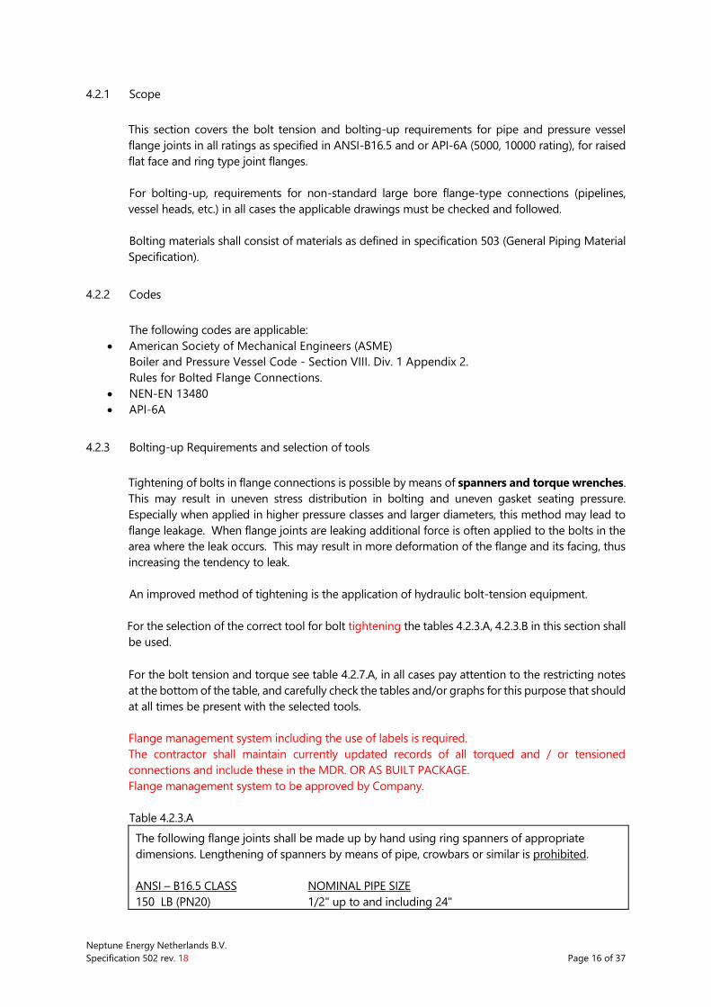
Table 4.2.3.A
The following flange joints shall be made up by hand using ring spanners of appropriate
dimensions. Lengthening of spanners by means of pipe, crowbars or similar is prohibited.
ANSI – B16.5 CLASS NOMINAL PIPE SIZE
150 LB (PN20) 1/2" up to and including 24"
Neptune Energy Netherlands B.V.
Specification 502 rev. 18 Page 17 of 37
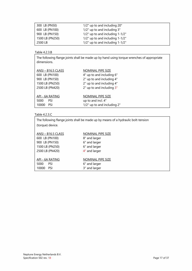
300 LB (PN50) 1/2" up to and including 20"
600 LB (PN100) 1/2" up to and including 3"
900 LB (PN150) 1/2" up to and including 1-1/2"
1500 LB (PN250) 1/2" up to and including 1-1/2"
2500 LB 1/2" up to and including 1-1/2"
Table 4.2.3.B
The following flange joints shall be made up by hand using torque wrenches of appropriate
dimensions.
ANSI – B16.5 CLASS NOMINAL PIPE SIZE
600 LB (PN100) 4" up to and including 6"
900 LB (PN150) 2" up to and including 4"
1500 LB (PN250) 2" up to and including 4"
2500 LB (PN420) 2" up to and including 3"
API - 6A RATING NOMINAL PIPE SIZE
5000 PSI up to and incl. 4"
10000 PSI 1/2" up to and including 2"
Table 4.2.3.C
The following flange joints shall be made up by means of a hydraulic bolt-tension
(torque) device.
ANSI – B16.5 CLASS NOMINAL PIPE SIZE
600 LB (PN100) 8" and larger
900 LB (PN150) 6" and larger
1500 LB (PN250) 6" and larger
2500 LB (PN420) 4" and larger
API - 6A RATING NOMINAL PIPE SIZE
5000 PSI 6" and larger
10000 PSI 3" and larger
Neptune Energy Netherlands B.V.
Specification 502 rev. 18 Page 18 of 37
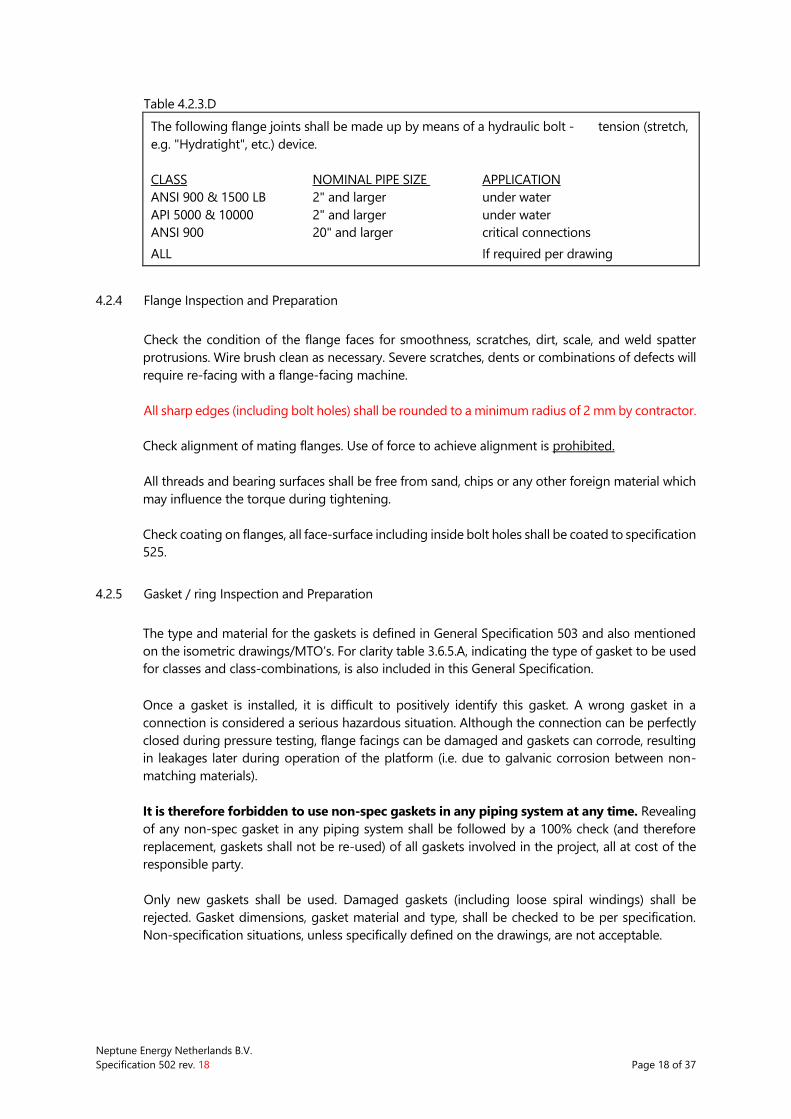
Table 4.2.3.D
The following flange joints shall be made up by means of a hydraulic bolt - tension (stretch,
e.g. "Hydratight", etc.) device.
CLASS NOMINAL PIPE SIZE APPLICATION
ANSI 900 & 1500 LB 2" and larger under water
API 5000 & 10000 2" and larger under water
ANSI 900 20" and larger critical connections
ALL If required per drawing
4.2.4 Flange Inspection and Preparation
Check the condition of the flange faces for smoothness, scratches, dirt, scale, and weld spatter
protrusions. Wire brush clean as necessary. Severe scratches, dents or combinations of defects will
require re-facing with a flange-facing machine.
All sharp edges (including bolt holes) shall be rounded to a minimum radius of 2 mm by contractor.
Check alignment of mating flanges. Use of force to achieve alignment is prohibited.
All threads and bearing surfaces shall be free from sand, chips or any other foreign material which
may influence the torque during tightening.
Check coating on flanges, all face-surface including inside bolt holes shall be coated to specification
525.
4.2.5 Gasket / ring Inspection and Preparation
The type and material for the gaskets is defined in General Specification 503 and also mentioned
on the isometric drawings/MTO’s. For clarity table 3.6.5.A, indicating the type of gasket to be used
for classes and class-combinations, is also included in this General Specification.
Once a gasket is installed, it is difficult to positively identify this gasket. A wrong gasket in a
connection is considered a serious hazardous situation. Although the connection can be perfectly
closed during pressure testing, flange facings can be damaged and gaskets can corrode, resulting
in leakages later during operation of the platform (i.e. due to galvanic corrosion between non-
matching materials).
It is therefore forbidden to use non-spec gaskets in any piping system at any time. Revealing
of any non-spec gasket in any piping system shall be followed by a 100% check (and therefore
replacement, gaskets shall not be re-used) of all gaskets involved in the project, all at cost of the
responsible party.
Only new gaskets shall be used. Damaged gaskets (including loose spiral windings) shall be
rejected. Gasket dimensions, gasket material and type, shall be checked to be per specification.
Non-specification situations, unless specifically defined on the drawings, are not acceptable.
Neptune Energy Netherlands B.V.
Specification 502 rev. 18 Page 19 of 37
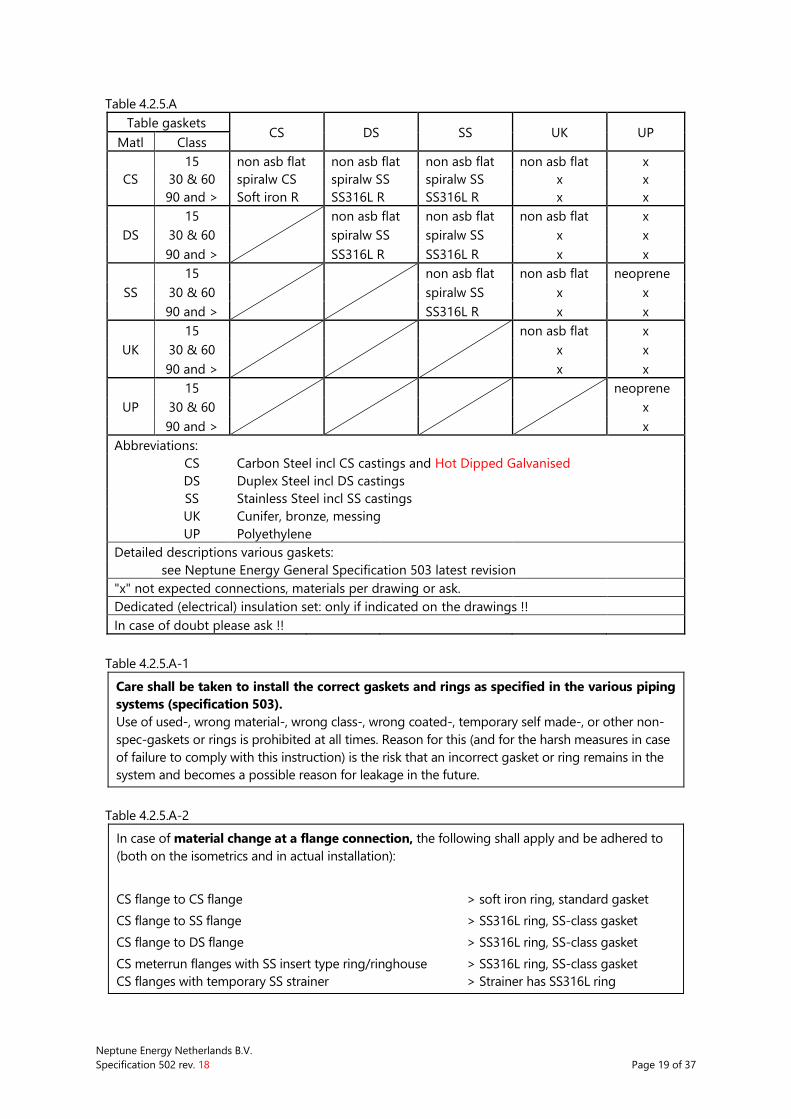
Table 4.2.5.A
Table gaskets CS DS SS UK UP
Matl Class
15 non asb flat non asb flat non asb flat non asb flat x
CS 30 & 60 spiralw CS spiralw SS spiralw SS x x
90 and > Soft iron R SS316L R SS316L R x x
15
non asb flat non asb flat non asb flat x
DS 30 & 60 spiralw SS spiralw SS x x
90 and > SS316L R SS316L R x x
15
non asb flat non asb flat neoprene
SS 30 & 60 spiralw SS x x
90 and > SS316L R x x
15
non asb flat x
UK 30 & 60 x x
90 and > x x
15
neoprene
UP 30 & 60 x
90 and > x
Abbreviations:
CS Carbon Steel incl CS castings and Hot Dipped Galvanised
DS Duplex Steel incl DS castings
SS Stainless Steel incl SS castings
UK Cunifer, bronze, messing
UP Polyethylene
Detailed descriptions various gaskets:
see Neptune Energy General Specification 503 latest revision
"x" not expected connections, materials per drawing or ask.
Dedicated (electrical) insulation set: only if indicated on the drawings !!
In case of doubt please ask !!
Table 4.2.5.A-1
Care shall be taken to install the correct gaskets and rings as specified in the various piping
systems (specification 503).
Use of used-, wrong material-, wrong class-, wrong coated-, temporary self made-, or other non-
spec-gaskets or rings is prohibited at all times. Reason for this (and for the harsh measures in case
of failure to comply with this instruction) is the risk that an incorrect gasket or ring remains in the
system and becomes a possible reason for leakage in the future.
Table 4.2.5.A-2
In case of material change at a flange connection, the following shall apply and be adhered to
(both on the isometrics and in actual installation):
CS flange to CS flange > soft iron ring, standard gasket
CS flange to SS flange > SS316L ring, SS-class gasket
CS flange to DS flange > SS316L ring, SS-class gasket
CS meterrun flanges with SS insert type ring/ringhouse > SS316L ring, SS-class gasket
CS flanges with temporary SS strainer > Strainer has SS316L ring
Neptune Energy Netherlands B.V.
Specification 502 rev. 18 Page 20 of 37
4.2.6 Stud / nut inspection and preparation
Check thread on stud and nut. Minor damage of tread on stud well in between the nuts may be
repaired, including coating.
Complete coating must be intact.
Nut to flange contact surface shall be clean and smooth, avoid damage to coating in consultation
with Company.
Studs area for nuts to be lubricated with approved lubricant. The same lubricant should be used
consistently on all joints especially when controlled bolt tightening is required (see tables 3.6.3).
The lubricant for alu-coated studbolts shall be "Molyslip Alumslip".
4.2.7 Installation Procedure - Tensioning
Install gasket and all bolts and nuts before any tensioning.
Note: It is recognized that applied torque to a nut member is only one of several ways to
approximate tension and unit stress in a studbolt. Tabulated values (table 3.6.7A) are
presented for convenience and guidance only. Some factors which affect the
relationship between nut torque and boltstress are:
Tread pitch, pitch diameter, and tread form.
Surface finish of thread faces and nut bearing surface area.
Degree of parallelism of nut bearing area with flange face.
Type of lubrication and coating of the treads and nut bearing surface area.
Table can be used as a guideline for general purpose application (shaded area). For
non-standard applications dedicated calculation based on found materials,
geometries and circumstances can be made.
Develop the required bolt stress as per table 3.6.7.A "Bolt torque values" in a minimum of three
steps, following a tightening-up procedure as outlined per figure 3.6.7.B "Bolt-up sequence
description".
Note: if more than 30 % of the final bolt stress is applied during the first step, serious damage
will be done to the spiral-wound gasket and subsequent tightening cannot offset this
damage. Gasket shall be rejected.
Requirements are based on bolts with UNC/8UN Thread; friction coefficient of 0.12 or 0.13.
Lubricant with another coefficient of friction will require interpretation of table or recalculation of
bolt torque.
Neptune Energy Netherlands B.V.
Specification 502 rev. 18 Page 21 of 37
4.2.8 Tools
All tools used for tightening shall fit the hexagon of bolts and nuts without damaging the width
across flats and be suitable for matching nuts in accordance with ANSI B 18.2.2.
Hydraulic Torque Wrench Device
The torque wrench device, including adapters, shall be suitable for matching bolt size. Each Torque
Wrench Device shall be accompanied with a clear manual (in language of personnel involved),
indicating clearly the relationship between read-out hydraulic pressure and moment applied on
nut.
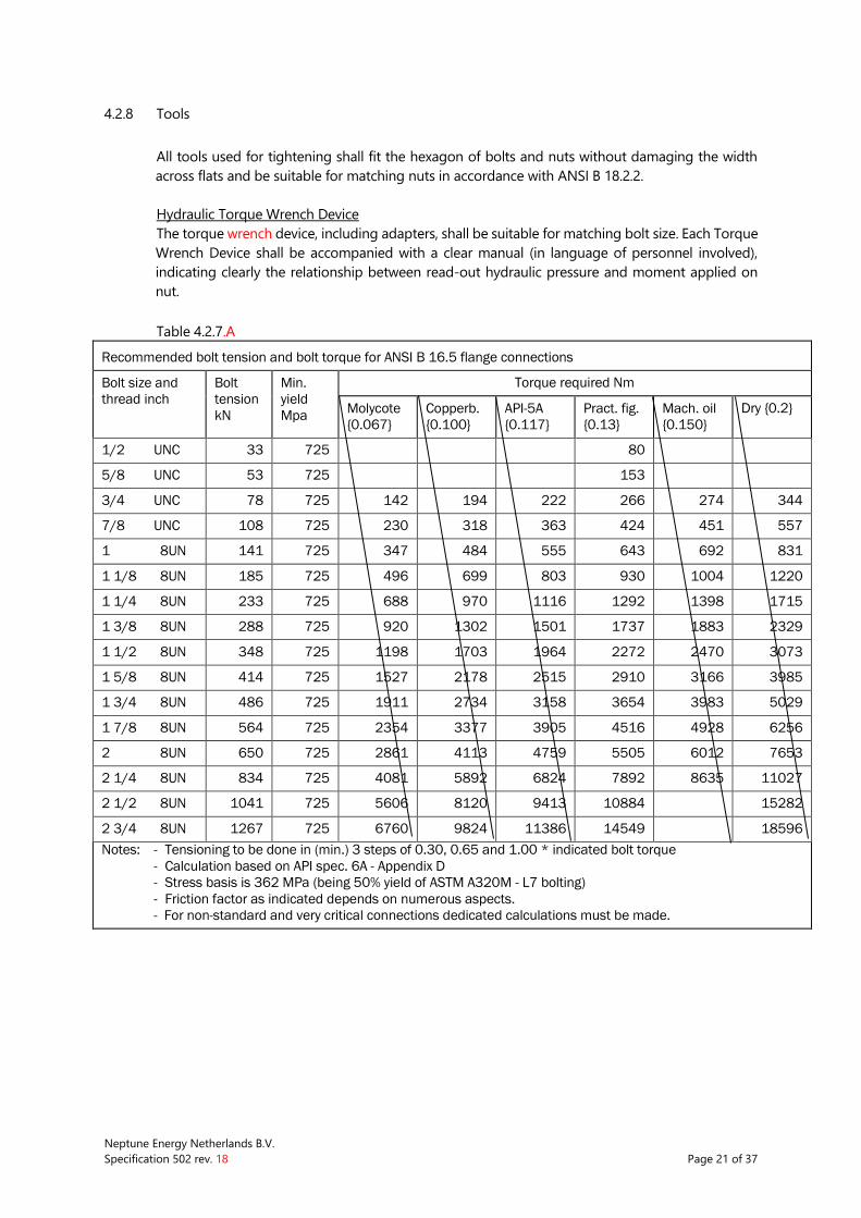
Table 4.2.7.A
Recommended bolt tension and bolt torque for ANSI B 16.5 flange connections
Bolt size and
thread inch
Bolt
tension
kN
Min.
yield
Mpa
Torque required Nm
Molycote
{0.067}
Copperb.
{0.100}
API-5A
{0.117}
Pract. fig.
{0.13}
Mach. oil
{0.150}
Dry {0.2}
1/2 UNC 33 725 80
5/8 UNC 53 725 153
3/4 UNC 78 725 142 194 222 266 274 344
7/8 UNC 108 725 230 318 363 424 451 557
1 8UN 141 725 347 484 555 643 692 831
1 1/8 8UN 185 725 496 699 803 930 1004 1220
1 1/4 8UN 233 725 688 970 1116 1292 1398 1715
1 3/8 8UN 288 725 920 1302 1501 1737 1883 2329
1 1/2 8UN 348 725 1198 1703 1964 2272 2470 3073
1 5/8 8UN 414 725 1527 2178 2515 2910 3166 3985
1 3/4 8UN 486 725 1911 2734 3158 3654 3983 5029
1 7/8 8UN 564 725 2354 3377 3905 4516 4928 6256
2 8UN 650 725 2861 4113 4759 5505 6012 7653
2 1/4 8UN 834 725 4081 5892 6824 7892 8635 11027
2 1/2 8UN 1041 725 5606 8120 9413 10884 15282
2 3/4 8UN 1267 725 6760 9824 11386 14549 18596
Notes: - Tensioning to be done in (min.) 3 steps of 0.30, 0.65 and 1.00 * indicated bolt torque
- Calculation based on API spec. 6A - Appendix D
- Stress basis is 362 MPa (being 50% yield of ASTM A320M - L7 bolting)
- Friction factor as indicated depends on numerous aspects.
- For non-standard and very critical connections dedicated calculations must be made.
Neptune Energy Netherlands B.V.
Specification 502 rev. 18 Page 22 of 37
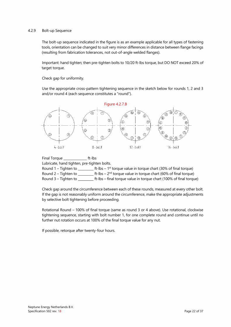
4.2.9 Bolt-up Sequence
The bolt-up sequence indicated in the figure is as an example applicable for all types of fastening
tools, orientation can be changed to suit very minor differences in distance between flange facings
(resulting from fabrication tolerances, not out-of-angle welded flanges).
Important: hand tighten; then pre-tighten bolts to 10/20 ft-lbs torque, but DO NOT exceed 20% of
target torque.
Check gap for uniformity.
Use the appropriate cross-pattern tightening sequence in the sketch below for rounds 1, 2 and 3
and/or round 4 (each sequence constitutes a "round").
Figure 4.2.7.B
Final Torque _______________ ft-lbs
Lubricate, hand tighten, pre-tighten bolts.
Round 1 – Tighten to __________ ft-lbs – 1st torque value in torque chart (30% of final torque)
Round 2 – Tighten to __________ ft-lbs – 2nd torque value in torque chart (60% of final torque)
Round 3 – Tighten to __________ ft-lbs – final torque value in torque chart (100% of final torque)
Check gap around the circumference between each of these rounds, measured at every other bolt.
If the gap is not reasonably uniform around the circumference, make the appropriate adjustments
by selective bolt tightening before proceeding.
Rotational Round – 100% of final torque (same as round 3 or 4 above). Use rotational, clockwise
tightening sequence, starting with bolt number 1, for one complete round and continue until no
further nut rotation occurs at 100% of the final torque value for any nut.
If possible, retorque after twenty-four hours.
Neptune Energy Netherlands B.V.
Specification 502 rev. 18 Page 23 of 37
4.3 THREADED CONNECTIONS
4.3.1 Guidelines for the making of small-bore NPT connections
Threaded (NPT) piping connections and the application of various types of PTFE tape and thread
sealant.
General rules to check NPT thread connections (ANSI B1.20.1).
correct selection of materials for services, pressure and temperature (specification!),
check state and installation of cutting blocks (direction and following sequence) if male tread
is cut on pipe, use cutting oil
use of proper and undamaged thread on both male and female thread side,
the proper use of suitable sealant or tape,
correct installation and supporting of pipe,
both male and female thread must be smooth, no burrs, cuts or other irregularities can be
accepted,
minor corrosion can be removed from the thread, actually corroded thread can not be
accepted,
without tape or sealant the parts to be connected should allow 4 to 5 rotations, at least 4
threads should be engaged,
with tape or sealant it should be possible to make up the parts 3 to 4 rotations without
excessive force.
DO NOT:
unscrew an already made up thread connection after application of sealant, not even a little,
use extra sealant or tape to fix a doubtful thread,
use excessive force to make up of (non-fitting) threads.
Special care is required for the mounting/installing of plugs.
Plugs are often used numerous times on the same or a new location and therefore the threads can
be worn.
Threaded connections used for instrumentation (actual instrument, instrument air, and others) are
considered to be made per piping specifications.
For SS tubing connections, as widely in use within instrumentation and otherwise, the piping
specifications are not to be used.
All instrument tubing systems to be made according to specifications and manufacturers
recommendations.
The Use of PTFE Tape
Although PTFE tape can be applied without problems for numerous applications, it should be
realised that the application is limited by the physical properties of PTFE tape. The table (4.3.1.A) in
this section gives a summary of the possibilities for various types of tape and sealant. This table is
based on the manufacturer recommendations and practical experience.
At this moment no "tailor made" code is available for all situations.
Most commercially available tapes are of "Giveg class 0.2".
Neptune Energy Netherlands B.V.
Specification 502 rev. 18 Page 24 of 37
Based on experience it can be said that the use of PTFE tape can give acceptable results. The "Giveg
keurmerk" indicates that subjected tapes are fabricated controlled and the chemical properties are
checked. Therefore this must be checked before use.
PTFE tape shall be applied as follows:
In the diameter range up to 1" the PTFE tape (thickness 0.1 mm) can be used (See table.)
Tape to be applied to male thread, starting away from and working towards the pipe end, with a
tape overlap of 50%, wrap under slight tension to ensure that tape conforms to thread contours.
Only 3 to 4 layers can be applied, not more.
Do not use this tape for connections in pipe with a diameter above 1".
Alternative Thread Compounds
As alternative or addition to PTFE tape, numerous more or less liquid sealing materials are available.
At all times the manufacturers recommendations for these materials must be checked and
followed. Some (widely used) examples are included in table 3.7.1.A.
Any other brand, not listed, shall be submitted to company for approval.
4.3.2 Material problems in making threaded connections
The available piping specifications often leave the question for a practical solution for connecting
or matching two different materials un-answered. Especially on equipment with various materials
used, problems can occur.
Examples: - SS and duplex are very difficult materials to cut tread "in the field",
- Installation of threaded connections in duplex steel are very difficult, duplex-
duplex connections must be avoided completely (the male tread will cut
into the female side, far before the required number of treads is installed,
"galling").
- Tools (cutting blocks and others) for SS must be used for SS only.
Described problems should be identified and eliminated.
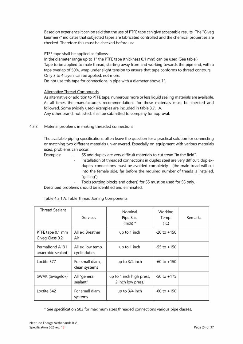
Table 4.3.1.A, Table Thread Joining Components
Thread Sealant
Services
Nominal
Pipe Size
(Inch) *
Working
Temp.
(C)
Remarks
PTFE tape 0.1 mm
Giveg Class 0.2
All ex. Breather
Air
up to 1 inch -20 to +150
PermaBond A131
anaerobic sealant
All ex. low temp.
cyclic duties
up to 1 inch -55 to +150
Loctite 577 For small diam.,
clean systems
up to 3/4 inch -60 to +150
SWAK (Swagelok) All "general
sealant"
up to 1 inch high press,
2 inch low press.
-50 to +175
Loctite 542 For small diam.
systems
up to 3/4 inch -60 to +150
* See specification 503 for maximum sizes threaded connections various pipe classes.
Neptune Energy Netherlands B.V.
Specification 502 rev. 18 Page 25 of 37
4.3.3 Galvanic corrosion and threaded connections
A possible problem with threaded connections is galvanic corrosion. Screwed connections made
up with different materials can result in a difference in electrical potential with the right (wrong)
medium this can cause galvanic corrosion. The sharp edges of the (usually male) thread can be
affected very quickly (without the possibility to detect this from the outside). This will result in a
complete collapse of the connection without warning.
Risk for galvanic corrosion can and must be identified during piping design, however, could still
cause problems during offshore use. This should be considered during piping installation and day-
to-day offshore maintenance as well.
5.0 REQUIREMENTS FOR NON CARBON STEEL AND GALVANISED PIPING
5.1 REQUIREMENTS FOR DUPLEX STEEL, SUPER DUPLEX STEEL (CLASS … DS) AND STAINLESS (S)
(Duplex = Ferritic/austenitic stainless steel from material type "Werkstoff Nr 1.4462").
(Super Duplex = Ferritic/austenitic stainless steel from material type "Werkstoff Nr 1.4501"
Welding of Super Duplex requires a different specification and will be provided by Company).
Duplex and Stainless Steel piping in general to be coated per General Specification 525 (note:
different end colours).
5.1.1 Handling Duplex steel (See Attachment I to this specification) and Stainless Steel.
Duplex and/or Stainless steel shall never be in direct contact with CS pipe supports. During
installation the correct measures shall be taken to ensure this.
5.1.2 Welding of Duplex steel and Stainless (316L)
For the requirements of welding of Duplex steel reference is made to the applicable attachment to
this specification.
Any welding of / to Duplex steel shall be performed in strict accordance with this document
(Attachment I).
5.1.3 Pickling and passivating of Duplex steel and Stainless (316L)
After welding and before coating all duplex pipe spools shall be pickled and passivated by method
of bath emersion (specification to be submitted by Fabricator and approved by Company).
Field welds shall be avoided; in case field welds can not be avoided completely, a dedicated
procedure for welding and treatment after welding shall be prepared by Contractor and submitted
to Company for approval.
After welding the outside weld area, Stainless Steel shall be pickled and passivated before blasting
and coating.
5.2 REQUIREMENTS FOR CUNIFER PIPING (CLASS 15UK)
Neptune Energy Netherlands B.V.
Specification 502 rev. 18 Page 26 of 37
5.2.1 General
Cunifer as per ASTM B466, is often referred to as "Cunifer 10" or "offshore quality Cunifer". Cunifer
material can deviate from standard material specifications for dimensions and shape of specially
tee's and flanges.
Cunifer is used with wt's far less than wt for comparable CS piping. For this reason the spools are
rather vulnerable, therefor extra attention in handling and supporting is required.
Cunifer piping shall not be coated, CS parts (flange backing-rings, valves, studbolts & nuts etc. and
obviously supporting) are to be coated or HD galvanized.
(Note : only possible method to coat CS backing-rings to spec. is to coat these before assembling
spools, backing rings are also delivered HD-galvanised, this is in general also acceptable.)
For systems that are normally drained/empty (dry sections deluge systems normally fabricated
from cunifer/class 15UK), after installation, pressure testing and commissioning, drainholes shall be
drilled, locations subject to approval by Company.
5.2.2 Handling
Any direct contact between Cunifer and carbon steel components shall be avoided.
Dedicated tools that have not been used on any other material shall be used.
Earthing clamps for welding and cutting shall be made of bronze.
Handling equipment, such as slings, hooks and lift truck forks shall be protected by clean
wood, cloth or plastic buffers to avoid contact with the surface.
Cunifer shall be stored indoors, it shall be protected from moisture, dust, salt, iron particles
and other matters that may initiate corrosion.
Cunifer shall never be in direct contact with CS pipe supports. During installation the correct
measures shall be taken to ensure this.
Supporting of Cunifer shall be based on (rubber) lined U-bolts with lining pieces in
accordance with General Specification 504.
5.2.3 Welding
Welding of Cunifer will be performed to requirements as laid down in the general welding
requirements description in this specification, with the following additional remarks:
welding process will be a non-slag process (in general considering the small wallthickness a
TIG process will be used), welding process and consumables will suit the Cunifer and welding
material producers guidelines for processing same.
weld material and HAZ will have mechanical and corrosion qualities at least comparable to
original material.
welding with 70/30 welding consumables.
small diameter fittings may require brazing; proper procedure to be issued for approval. Silver
brazing alloys to be used as consumable.
5.3 REQUIREMENTS FOR POLY ETHYLENE PIPING (CLASS 15UP)
Neptune Energy Netherlands B.V.
Specification 502 rev. 18 Page 27 of 37
PE-piping in general requires specialists to fabricate and install. In general material to be processed
to piping system to manufacturers recommendation for design, welding (fusing) supporting (entire
length), etc..
PE-piping not to be coated.
5.4 REQUIREMENTS FOR HOT DIP GALVANISED PIPING (CLASS 15U)
Spools class 15U shall be HD-Galvanised (per specification 525) after fabrication of spools. Field
welds are not allowed. Where required additional flange connections to be installed. After
galvanising and before installation flange facings and threaded connections to be checked for and
if necessary cleaned from excessive zinc.
5.5 CLASS U2
Class 2 shall be installed by personnel trained and certified by supplier Geberit.
Neptune Energy Netherlands B.V.
Specification 502 rev. 18 Page 28 of 37
5.5 SYSTEMS THAT REQUIRE EXTRA GRADE OF CLEANING
Some systems require extra cleaning by means of pickling and flushing because of their process
function. This is always the case for the systems indicated below, and further as indicated on the
drawings and further documents. Procedure to be prepared by Contractor and approved by
Company.
Systems to be pickled and passivated as a system for process reasons:
Hydraulical- and lube-oil systems
Piping upstream gas-compressors downstream last filter (note: possible bypass loops to be
included).
See also remarks with “testing” and “medium”.
Systems to be cleaned as hydraulic control piping.
Cleaning shall be carried out on hydraulic systems, with exception of the hydraulic cabinets and
wellhead control panels since they have been cleaned by the panel Supplier. All hydraulic lines
shall be cleaned to a minimum cleanliness level to ISO 4406 class 15/12 (equal to NAS 1638
class 6).
Prior to commencement a cleaning procedure shall be issued for review to Company (cleaning
procedure can be part of the system test procedure).
Cleaning reports and records of samples shall be available for review during FAT.
Items that could be damaged due to cleaning shall be removed or by-passed during cleaning.
Items which create high restrictions due to orifice dimensions shall be removed or by-passed.
Cleaning procedure must include as minimum
- method of cleaning
- define the extent of cleaning
- method of sampling and examination
- description of the cleaning unit (flow rate, pressure, velocity. filter mesh size)
Flushing shall be performed with:
- fluid as used in the system is preferred.
- flow shall be turbulent at all points
- temperature shall be as high as possible
When the cleaning is completed, the tubes remain filled and all connection shall be plugged
with metal plugs. In case s different cleaning fluid is used, this shall be removed and tubes
shall be blown out with dry nitrogen.
Important note :
All installed components such as valves; regulators shall be suitable to operate without
problems with oil cleanliness to ISO 4406 class 19/16 (equal to NAS 1638 class 10)
1
6
Neptune Energy Netherlands B.V.
Specification 502 rev. 18 Page 29 of 37
6.0 FLUSHING AND PRESSURE TESTING
6.1 SCOPE
In this specification described method of flushing and testing is applicable for piping systems on
platforms and installations. For (subsea) transportlines dedicated procedures per applicable codes
(NEN 3560) are required.
6.2 FLUSHING
After installation and before pressure testing piping systems shall be thoroughly flushed. Result
shall be a clean piping system. At least all debris and contamination of the piping system shall be
removed. Depending on the use of the piping system, further requirements shall be applicable
(hydraulic systems, fuel systems, etc.).
Flushing in general shall take place with fresh water ; if water in the system is a problem, alternatives
shall be used (air for air-system, oil for hydraulic system, etc.) Flush procedure(s) to be issued for
approval to Company.
Flushing water used for CS shall not be used for SS or DS.
Water for SS or DS shall not contain more than 20 ppm chlorides.
Where in-line items can be expected to become any obstruction to flush-out debris, or where the
possibility of damage to system or in-line items exists, these items shall be removed before flushing
(all types of valves, instruments, filters, etc.).
Finished prefabbed galvanised pipe spools to be flushed with potable water to detect extreme
layer thickness or blockage of the pipespool. (witnessed by Company).
Alternative methods to be approved by Company.
Systems shall be delivered dry and closed. This can be done with clean hot air, vacuum drying, etc.
Proposal is to be submitted to Company for approval before start erection.
6.2.1 Systems that require extra grade of cleaning.
Some systems require extra cleaning by means of pickling and flushing because of their
process function.This is always the case for the systems indicated below, and further as
indicated on the drawings and further documents. Procedure to be prepared by Contractor
and approved by Company.
Systems to be pickled and passivated as a system for process reasons:
Hydraulical- and lube-oil systems
Piping upstream gas-compressors downstream last filter (note: possible bypass loops to be
included).
See also remarks with “testing” and “medium”.
6.2.2 Systems to be cleaned as hydraulic control piping.
Cleaning shall be carried out on hydraulic systems, with exception of the hydraulic cabinets
and wellhead control panels since they have been cleaned by the panel Supplier. All hydraulic
lines shall be cleaned to a minimum cleanliness level to ISO 4406 class 15/12 (equal to NAS
1638 class 6).
Neptune Energy Netherlands B.V.
Specification 502 rev. 18 Page 30 of 37
Prior to commencement a cleaning procedure shall be issued for review to Company (cleaning
procedure can be part of the system test procedure).
Cleaning reports and records of samples shall be available for review during FAT.
Items that could be damaged due to cleaning shall be removed or by-passed during cleaning.
Items which create high restrictions due to orifice dimensions shall be removed or by-passed.
Cleaning procedure must include as minimum
method of cleaning
define the extent of cleaning
method of sampling and examination
description of the cleaning unit (flow rate, pressure, velocity. filter mesh size)
6.3 TESTING AND TEST SYSTEMS
6.3.1 Procedure Onshore
Note: EPI guideline: DOP-PD-15-0037 (for offshore application) will be included in the
Offshore Management System.
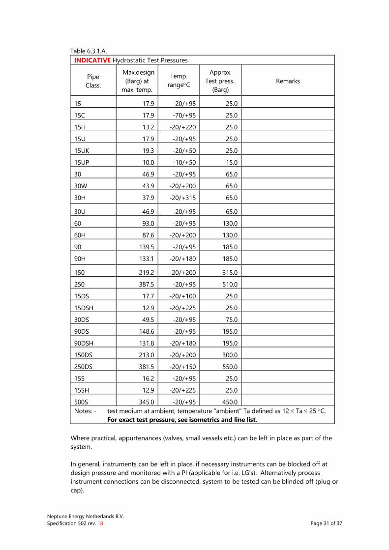
Prior to initial operation, each installed piping system shall be pressure and leak tested in
accordance with PED and Company standard practice to assure mechanical strength and
tightness. Table 6.3.1.A is for information only. DAD’s prepared per PED give required test
pressure. All Pressure testing shall be done in accordance with a Contractor prepared and
Company approved hydro test procedure. A test diagram shall be made for determining the
test systems.
Test pressure will be indicated on the AFC-drawings, this shall be checked versus pressure on
DAD’s.
Contractor to check allowed test pressure for all components that are included
Pressure test procedures shall be made in accordance with NEN-EN 13480 and Company
standard practice.
For new platforms, modules or skids complete systems shall be tested with all pipe supports
fitted. Nitrogen shall be used. Spring supports shall remain in the locked position. This testing
shall be done after fabrication and before leaving the fabrication yard as part of the
fabrication scope (pre-commissioning).
Neptune Energy Netherlands B.V.
Specification 502 rev. 18 Page 31 of 37
Table 6.3.1.A.
INDICATIVE Hydrostatic Test Pressures
Pipe
Class.
Max.design
(Barg) at
max. temp.
Temp.
rangeC
Approx.
Test press..
(Barg)
Remarks
15 17.9 -20/+95 25.0
15C 17.9 -70/+95 25.0
15H 13.2 -20/+220 25.0
15U 17.9 -20/+95 25.0
15UK 19.3 -20/+50 25.0
15UP 10.0 -10/+50 15.0
30 46.9 -20/+95 65.0
30W 43.9 -20/+200 65.0
30H 37.9 -20/+315 65.0
30U 46.9 -20/+95 65.0
60 93.0 -20/+95 130.0
60H 87.6 -20/+200 130.0
90 139.5 -20/+95 185.0
90H 133.1 -20/+180 185.0
150 219.2 -20/+200 315.0
250 387.5 -20/+95 510.0
15DS 17.7 -20/+100 25.0
15DSH 12.9 -20/+225 25.0
30DS 49.5 -20/+95 75.0
90DS 148.6 -20/+95 195.0
90DSH 131.8 -20/+180 195.0
150DS 213.0 -20/+200 300.0
250DS 381.5 -20/+150 550.0
15S 16.2 -20/+95 25.0
15SH 12.9 -20/+225 25.0
500S 345.0 -20/+95 450.0
Notes: - test medium at ambient; temperature "ambient" Ta defined as 12 Ta 25 C.
For exact test pressure, see isometrics and line list.
Where practical, appurtenances (valves, small vessels etc.) can be left in place as part of the
system.
In general, instruments can be left in place, if necessary instruments can be blocked off at
design pressure and monitored with a PI (applicable for i.e. LG's). Alternatively process
instrument connections can be disconnected, system to be tested can be blinded off (plug or
cap).
Neptune Energy Netherlands B.V.
Specification 502 rev. 18 Page 32 of 37
At all times the following items shall be considered:
the extra weight of vessel system contents (deck structure, supporting)
check for all items on maximum allowable pressure or possibly vacuum,
check for all valves to allowable pressure in open position and if applicable in closed position,
check required position ball / internals,
check for the absolute absence of risk on damage of internals appurtenances or vessels
either by pressure, by weight or by medium as result of pressure testing or presence. Filters
and filter type vessel internals shall not be part of pressure test with water.
Operation and/or maintenance instructions on items involved shall be carefully checked for
required position before, during and after pressure test.
Relief- and check valves shall be removed. Temporary spools may be used to avoid splitting
the test system.
No test systems shall be coupled by tubing unless agreed otherwise.
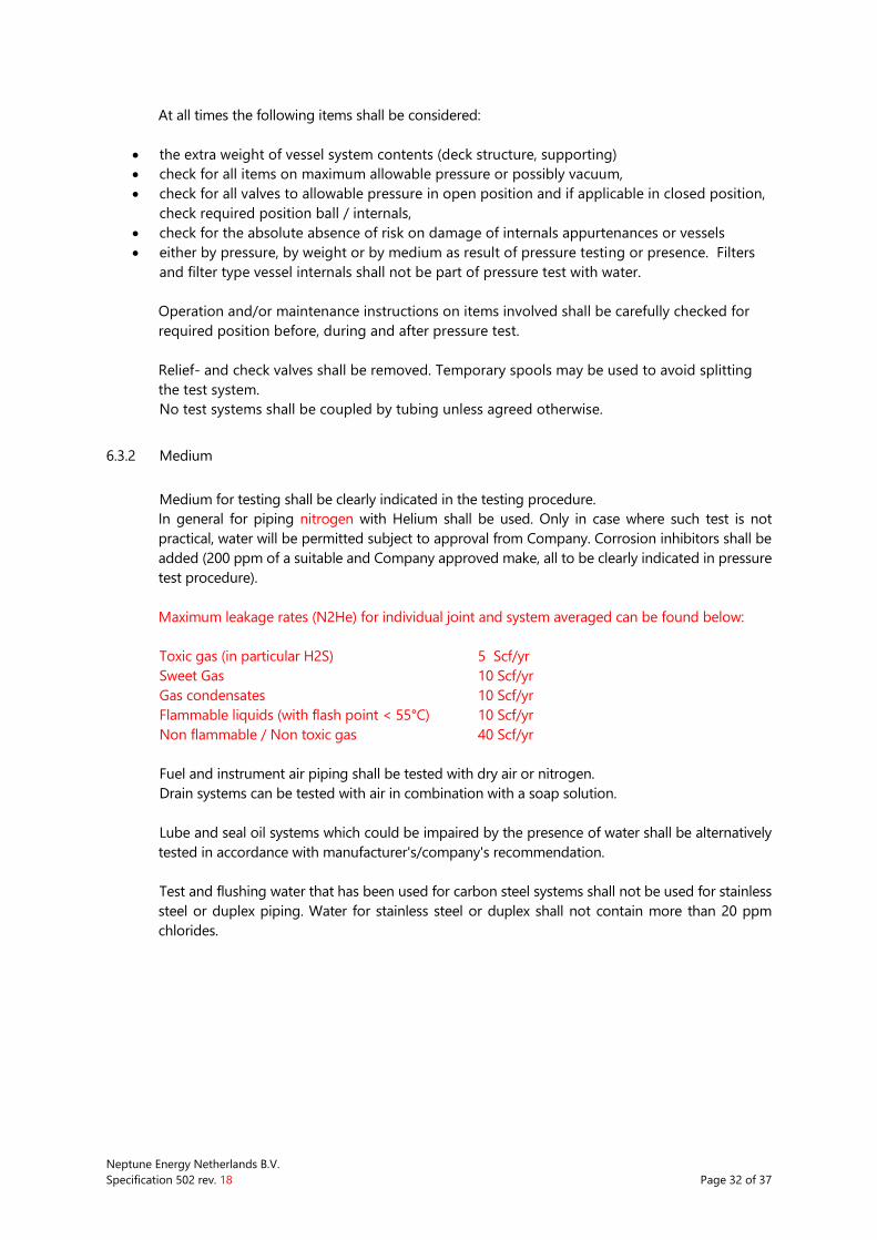
6.3.2 Medium
Medium for testing shall be clearly indicated in the testing procedure.
In general for piping nitrogen with Helium shall be used. Only in case where such test is not
practical, water will be permitted subject to approval from Company. Corrosion inhibitors shall be
added (200 ppm of a suitable and Company approved make, all to be clearly indicated in pressure
test procedure).
Maximum leakage rates (N2He) for individual joint and system averaged can be found below:
Toxic gas (in particular H2S) 5 Scf/yr
Sweet Gas 10 Scf/yr
Gas condensates 10 Scf/yr
Flammable liquids (with flash point < 55°C) 10 Scf/yr
Non flammable / Non toxic gas 40 Scf/yr
Fuel and instrument air piping shall be tested with dry air or nitrogen.
Drain systems can be tested with air in combination with a soap solution.
Lube and seal oil systems which could be impaired by the presence of water shall be alternatively
tested in accordance with manufacturer's/company's recommendation.
Test and flushing water that has been used for carbon steel systems shall not be used for stainless
steel or duplex piping. Water for stainless steel or duplex shall not contain more than 20 ppm
chlorides.
Neptune Energy Netherlands B.V.
Specification 502 rev. 18 Page 33 of 37
6.3.3 Testing and recording
Piping systems shall be thoroughly flushed and filled with medium selected for testing (see above).
The medium shall have ample time for setting and to allow the entrapped air to be vented.
For system tests each pressure test shall be monitored by one recorder, a thermometer and two
pressure gauges one of which is connected to the highest point of the test system.
Recorders and gauges shall be calibrated and certified in accordance with the NoBo requirements
and approved and accepted by Company.
The certificates shall be kept ready for inspection on site.
No testing shall be performed when ambient temperature is below 10 degrees C.
The minimum test pressure shall be measured at the highest point of the system.
If tested with water the test system shall be kept under pressure for settling until all entrapped air
is dissolved into the water. After approval of NoBo or Company the testing period starts and shall
be recorded. The pressure shall be maintained for the period mentioned in the pressure test
procedure or as long is required by NoBo or Company.
If pads or saddles have been installed at branch connections, ventholes shall be carefully inspected
to reveal any leakage during testing.
Ventholes shall be left open or plugged with a soft material not being able to sustain any pressure.
Each weld, flange connection and piece of equipment shall be carefully checked for leaks during
the test. Any leaks found shall be corrected after de-pressurising the system.
After correction of leaks or defects, Contractor shall retest the system.
If, during the test period, the pressure changes due to temperature variations of the test medium
a correction calculation shall be part of the test report.
If the ambient temperature is considerably higher than the test medium, care shall be taken that,
due to expansion in case of liquid test medium, the pressure does not exceed the maximum test
pressure.
Neptune Energy Netherlands B.V.
Specification 502 rev. 18 Page 34 of 37
6.3.4 Preparation system after testing
After successful completion of the pressure test, the system shall be drained promptly and be
dried according to a Company approved procedure. The system shall be filled with nitrogen if
Company requires so.
Care shall be taken that each high point is vented and each low point is drained.
Draining shall be slow enough not to create a vacuum that possibly can be detrimental to the
system. Prior to blowing all bottom plugs shall be removed.
All duplex systems shall, after completion, prior to load out, be cleaned and flushed with an
approved solvent, dried with hot air or by vacuum and filled with nitrogen at 1 Bar min. and
sealed off.
System(s) shall be closed with blind-plates and spades, fabricated from plate / supplied by
Contractor. For duplex flanges stainless steel liners and spades shall be used. Spades shall be
painted pink and clearly visible, all studs / nuts shall be installed, the original gaskets etc. shall be
attached to the spade. A checklist showing all spades shall be made to enable off shore re-
installation of the joints.
After pressure testing and reinstatement of the complete system, extra attention shall be paid to
obtaining a completely closed and leak-free system onshore. This shall be done by a complete test
at design pressure with nitrogen with Helium. Before startup offshore, this shall be done in line with
commissioning plan. This shall be done with a complete service test at operating pressure.
6.3.5 Alternative methods
If no pressure testing is possible, alternative/additional testing might be acceptable but only after
consultation of and approval from Company- and if applicable NoBo representative.
6.3.6 Inspection and witnessing
All test shall be witnessed and approved by Company, and where applicable by NoBo"
representative. During the test the system shall be accessible for proper and safe inspection.
6.4 SAFETY DURING PRESSURE TESTING
Precautions shall be taken to ensure that the pressure test is done in a safe manner. It should be
kept in mind that a considerable amount of energy is present in the test medium under high
pressure.
Only personnel directly involved in the test shall be permitted in the vicinity.
Further if applicable the use of N2 to fill systems after pressure testing and draining the system,
shall be reason for extra attention, note N2 if inhaled in larger quantities is lethal.
Systems filled with N2 shall at all times be clearly marked with appropriate warning signs.
Neptune Energy Netherlands B.V.
Specification 502 rev. 18 Page 35 of 37
7.0 QC PIPING FABRICATION
7.1 GENERAL
The nature and extend of supervision and inspection during fabrication, installation and testing
shall be agreed between Company, NoBo (if applicable) and Contractor.
The general contents agreed shall be laid down by Contractor in a quality control plan / test and
inspection plan.
7.2 INSPECTION PIPING PREFABRICATION
Inspection on prefabrication shall guarantee as a minimum the following items:
check on use correct materials and adherence to material control procedures,
visual examination materials before use,
visual examination fit-up before welding,
inspection on working (incl. welding) per specifications
visual examination after welding
inspection on dimensions (both dimensions from drawing as fabrication-results (square,
straddled, straight, etc.),
Non Destructive Testing
Heat treatment
Coating
Dimensional inspection to drawings
Inspection as required for Class. Authority for piping where applicable
Documentation including As Built.
7.2.1 Preparation for coating
Before blasting / coating can commence, to avoid damage to vulnerable parts ( i.e. treads),
and contamination of insides of pipe spools etc. with blasting material, parts shall be
protected ( closed or alternative).
For this purpose dedicated materials shall be used ( plastic caps, tubes on treaded rods,
neoprene sheets, tape)
No screwed plugs, caps that contain any pressure, shall be used!
7.3 INSPECTION PIPING INSTALLATION
Inspection on installation shall guarantee as a minimum the following items:
inspections as indicated for prefabrication where applicable
handling, transport and storage of spools
strain-free installation of piping
extra attention of closing system to avoid contamination of piping systems and equipment to
be connected
Non Destructive Testing field welds
Coating inspection
Supporting
Documentation including As Built.
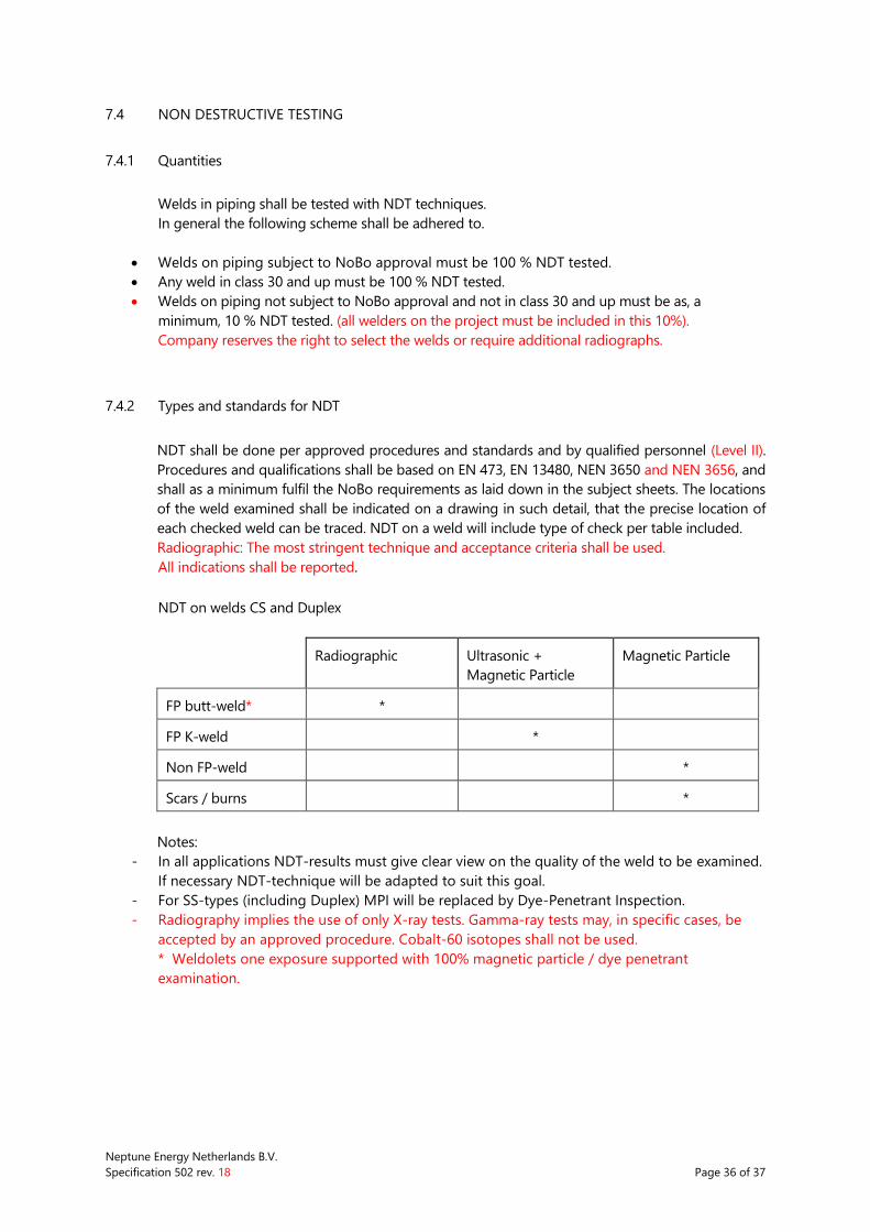
Neptune Energy Netherlands B.V.
Specification 502 rev. 18 Page 36 of 37
7.4 NON DESTRUCTIVE TESTING
7.4.1 Quantities
Welds in piping shall be tested with NDT techniques.
In general the following scheme shall be adhered to.
Welds on piping subject to NoBo approval must be 100 % NDT tested.
Any weld in class 30 and up must be 100 % NDT tested.
Welds on piping not subject to NoBo approval and not in class 30 and up must be as, a
minimum, 10 % NDT tested. (all welders on the project must be included in this 10%).
Company reserves the right to select the welds or require additional radiographs.
7.4.2 Types and standards for NDT
NDT shall be done per approved procedures and standards and by qualified personnel (Level II).
Procedures and qualifications shall be based on EN 473, EN 13480, NEN 3650 and NEN 3656, and
shall as a minimum fulfil the NoBo requirements as laid down in the subject sheets. The locations
of the weld examined shall be indicated on a drawing in such detail, that the precise location of
each checked weld can be traced. NDT on a weld will include type of check per table included.
Radiographic: The most stringent technique and acceptance criteria shall be used.
All indications shall be reported.
NDT on welds CS and Duplex
Radiographic Ultrasonic +
Magnetic Particle
Magnetic Particle
FP butt-weld* *
FP K-weld *
Non FP-weld *
Scars / burns *
Notes:
- In all applications NDT-results must give clear view on the quality of the weld to be examined.
If necessary NDT-technique will be adapted to suit this goal.
- For SS-types (including Duplex) MPI will be replaced by Dye-Penetrant Inspection.
- Radiography implies the use of only X-ray tests. Gamma-ray tests may, in specific cases, be
accepted by an approved procedure. Cobalt-60 isotopes shall not be used.
* Weldolets one exposure supported with 100% magnetic particle / dye penetrant
examination.
Neptune Energy Netherlands B.V.
Specification 502 rev. 18 Page 37 of 37
8.0 DOCUMENTATION
During fabrication and installation all relevant information shall be tabulated on the "Weld History
Sheet" attached to this specification or on an approved similar Quality Control Document, and shall
be issued to Company.
The extent of further documentation to be issued shall be agreed between Company and
Contractor.
9.0 DELIVERY AND TRANSPORT
If (pre-)fabricated spools are to be delivered to Neptune Energy for offshore installation (by
Contractor or by others), these spools will be:
clean and openings and ends closed, facings protected, properly stored to avoid damage.
transported in (open top) containers suitable for offshore transport and lifting or for larger
spools equipped with rigging for single point lifting. Lifting spools shall not contain tackwelded
items.
installation materials and/or supports shall be packed per spool and shipped with the subject
spools unless agreed otherwise.
have correct and clear marking (project/drawing/spool/platform/weight).
be accompanied by clear and complete paperwork and packing lists.
Release note prepared by contractor, for signature Company representative.
10.0 ATTACHMENTS
Attachment I - Welding of ferritic/austenitic stainless steel
Attachment II - Weld history sheet
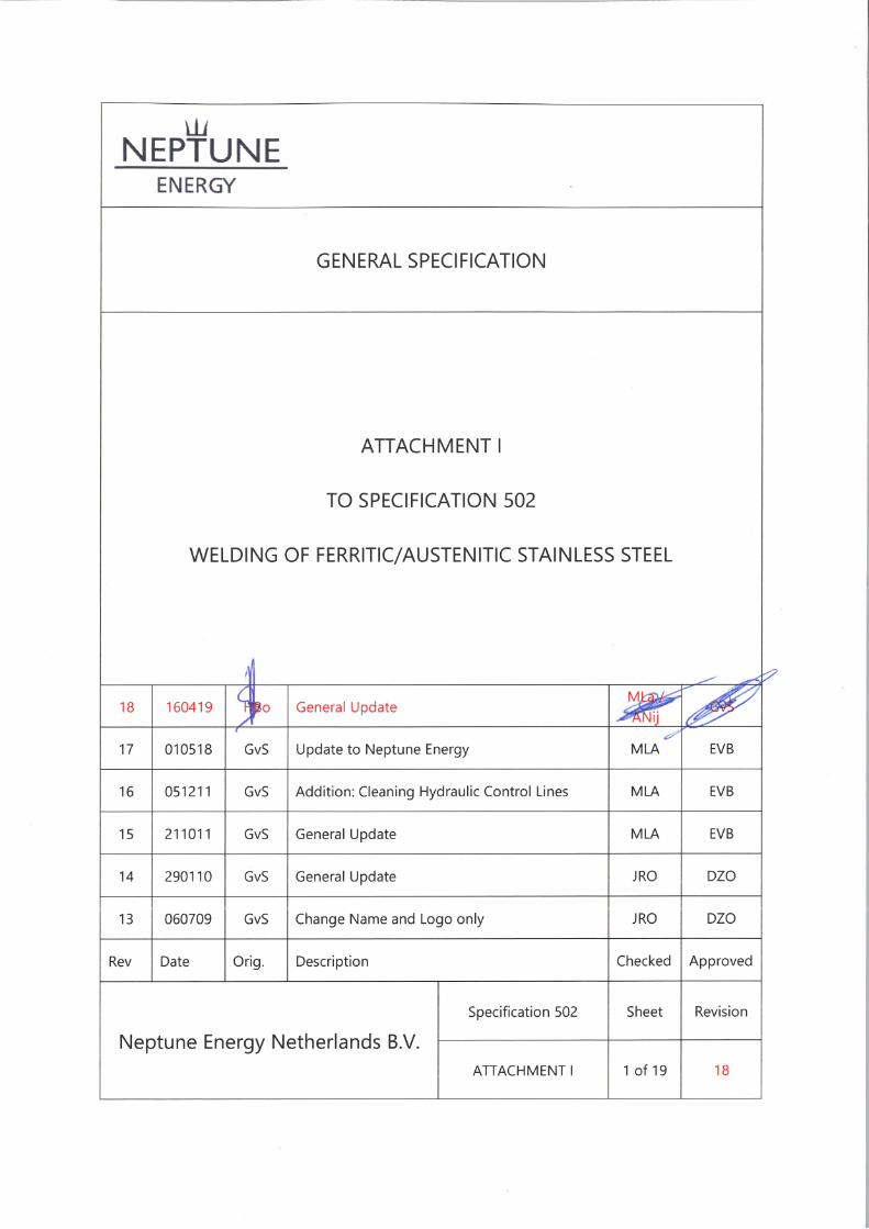
Neptune Energy Netherlands B.V.
Attachment I to Specification 502 rev. 18 Page 2 of 20
TABLE OF CONTENTS
1.0 GENERAL ......................................................................................................................................... 4
1.1 SCOPE ................................................................................................................................................................. 4 1.2 REFERENCES ..................................................................................................................................................... 4 1.3 ABBREVIATIONS ............................................................................................................................................. 4 1.4 TRANSPORT, STORAGE HANDLING AND PREPARATION ............................................................. 5 1.5 DOCUMENTATION ........................................................................................................................................ 5
2.0 WELDING CONSUMABLES ........................................................................................................... 6
2.1 ELECTRODES, WIRE AND FLUX ................................................................................................................. 6 2.2 CONDITION OF STORAGE .......................................................................................................................... 6
3.0 WELDING PROCEDURES ............................................................................................................... 7
3.1 GENERAL ........................................................................................................................................................... 7 3.2 WELDING PROCEDURE SPECIFICATIONS WPS .................................................................................. 7 3.3 WELDING PROCEDURE QUALIFICATION WPQ .................................................................................. 8 3.4 PROCEDURE QUALIFICATION RECORD PQR ...................................................................................... 8 3.5 INSPECTION OF PROCEDURE QUALIFICATION TEST WELDS ...................................................... 8 3.6 QUALITY REQUIREMENTS .......................................................................................................................... 9
4.0 WELDERS'S COMPETENCE CERTIFICATES ............................................................................... 10
4.1 GENERAL ......................................................................................................................................................... 10 4.2 MARKING OF WELDS ................................................................................................................................. 10 4.3 APPLICABILITY OF WELDER AND WELDING OPERATOR QUALIFICATION ........................... 10 4.4 RETESTS ........................................................................................................................................................... 10 4.5 WELDER QUALIFICATION RECORD ...................................................................................................... 10
5.0 PRODUCTION WELDING ............................................................................................................ 11
5.1 GENERAL ......................................................................................................................................................... 11 5.2 WEATHER PROTECTION ............................................................................................................................ 11 5.3 HANDLING AND USAGE OF WELDING CONSUMABLES ............................................................. 12 5.4 WELDING END PREPARATION ............................................................................................................... 12 5.5 BACKING STRIPS .......................................................................................................................................... 12 5.6 WELDING PROCESS, POSITION AND PROGRESSION ................................................................... 12 5.6.1 Gas Tungsten Arc Welding GTAW (TIG) ........................................................................................ 12 5.6.2 Submerged-Arc Welding SAW .......................................................................................................... 13 5.6.3 Shielded Metal Arc Welding SMAW ............................................................................................... 13 5.7 ARGON GAS PURGING INSIDE PIPES .................................................................................................. 13 5.8 HEAT INPUT, PREHEATING AND INTERPASS TEMPERATURES.................................................. 13 5.9 WELD INTERRUPTION ................................................................................................................................ 13 5.10 CLEANING ....................................................................................................................................................... 14 5.11 SIZE OF WELDS ............................................................................................................................................. 14 5.12 DISTANCE BETWEEN WELDS ................................................................................................................... 14 5.13 SOCKET WELDS............................................................................................................................................. 14 5.14 WELD FINISH ................................................................................................................................................. 14 5.15 POST WELD HEAT TREATMENT ............................................................................................................. 14
6.0 FABRICATION ............................................................................................................................... 15
6.1 GENERAL ......................................................................................................................................................... 15 6.2 BENDING ......................................................................................................................................................... 15
Neptune Energy Netherlands B.V.
Attachment I to Specification 502 rev. 18 Page 3 of 20
6.3 ALIGNMENT AND FIT-UPS ....................................................................................................................... 15 6.4 FINISHING OF SURFACES ......................................................................................................................... 16 6.5 PROTECTION OF PIPE ENDS .................................................................................................................... 16 6.6 REPAIR AND REMOVAL PROCEDURES ................................................................................................ 16
7.0 INSPECTION AND TESTING REQUIREMENTS ......................................................................... 18
7.1 GENERAL ......................................................................................................................................................... 18 7.2 METHODS OF INSPECTION, TESTING AND QUALITY REQUIREMENTS ................................. 18 7.2.1 Radiographic Examination (as noted or NoBo approved equivalent) ............................... 18 7.2.2 Ultrasonic Examination ......................................................................................................................... 18 7.2.3 Dye Penetrant Examination ................................................................................................................ 18 7.2.4 Pre-Welding Inspection ........................................................................................................................ 19 7.2.5 Inspection After Welding ..................................................................................................................... 19 7.2.6 Standards on Inspection ...................................................................................................................... 19 7.2.7 Weld Rejection Report .......................................................................................................................... 19 7.2.8 Right of Rejection ................................................................................................................................... 19 7.2.9 Assessment of Indications on Radiographs in the Pipe Material Adjacent to Welds
Being Inspected .......................................................................................................................................................... 19 7.2.10 Retests of Mechanical Properties ..................................................................................................... 19
Neptune Energy Netherlands B.V.
Attachment I to Specification 502 rev. 18 Page 4 of 20
1.0 GENERAL
1.1 SCOPE
This document as part of Specification 502 covers the requirements of welding and inspection
of duplex stainless steel shop and field fabricated piping.
Duplex stainless steel shall refer ferritic/austenitic stainless steel with a chemical composition
and mechanical properties as defined in VdTüV Werkstoffblatt Nr. 418, DIN Werkstoff Nr.
1.4462. For Transport Pipelines see NEN 3650 and offshore pipelines NEN 3656.
1.2 REFERENCES
The following specifications, codes and standards are to be considered where applicable. All
conflicts between the requirements of these relevant shall be referred to Company for
resolution. In case of conflicts between the documents listed and this document, the most
stringent requirement shall govern. The latest editions of the following standards and codes
shall apply:
"Pressure Equipment Directive" hereafter indicated as PED.
NEN-EN 13480.
Specification 503, Specification for pipe, fittings and valves.
EN 3834-2 Quality requirements for fusion welding of metallic materials.
1.3 ABBREVIATIONS
BM : Base Metal
EFN : Extended Ferrite Number
GMAW : Gas Metal Arc Welding
HAZ : Heat Affected Zone
IIW : International Institute of Welding
NDT : None Destructive Test
PQR : Procedure Qualification Record
QA : Quality Assurance
QC : Quality Control
SAW : Submerged Arc Welding
SMAW : Shielded Metal Arc Welding
WM : Weld Metal
WPS : Welding Procedure Specifications
WPQ : Welding Procedure Qualifications
Neptune Energy Netherlands B.V.
Attachment I to Specification 502 rev. 18 Page 5 of 20
1.4 TRANSPORT, STORAGE HANDLING AND PREPARATION
The following recommendations shall be adopted in every step in the manufacturing process
to reduce the risk of surface contamination of this type of stainless steel.
a) Any contact between stainless steel and carbon steel components shall be avoided.
Fabrication and storage of pipe spool shall be carried out in a separate area.
b) Before transportation and field installation each pipe spool shall be protected with tape.
c) Only stainless steel wire brushes that have not been used on any other material shall be used.
Grinding wheels used for stainless steel shall not have been used for other purposes. Tools
shall be clearly marked (i.e. colour coded) to indicate their designated use. Earthing clamps for
welding and cutting should be made of stainless steel.
d) Moisture shall be removed by carefully and controlled heating with a torch. Skin temperature
shall not exceed 150 °C.
e) Acetone (or approved equivalent) may be used for cleaning stainless steel surfaces. Caution:
Acetone is extremely flammable.
f) Arc cutting shall be done by using only plasma arc process.
g) Contamination of Duplex stainless steel with zinc, etc. will not be permitted.
h) Handling equipment, such as slings, hooks, and lift truck forks, shall be covered with clean
wood, cloth, or plastic buffers to exclude contact with the stainless steel surface. These
protection means shall be immediately replaced after any contact with carbon steel.
i) Stainless steel shall be stored indoors, or otherwise protected from moisture, dust, salt, iron
particles, and other matter that may initiate or cause corrosion.
j) If any construction activity is to be carried out in the vicinity of installed duplex or stainless
steel piping and/or equipment, adequate protection shall be provided to prevent any damage
before such construction work commences.
1.5 DOCUMENTATION
The following documentation shall be supplied by the Contractor and issued for approval
when applicable:
Mill certificates of materials used if the material is supplied by the Contractor (See
specification 503 and "PED")
Welding Procedure Specifications, Procedure qualification records and welders certificates
Procedures and methods for assembly, fabrication and handling
Procedures for repairs
Inspection and QC procedures
Non destructive testing records and radiograph films
Drawings indicating material and NDT locations
Hydrotest records, including instruments calibration data
Test & Inspection Plan
Neptune Energy Netherlands B.V.
Attachment I to Specification 502 rev. 18 Page 6 of 20
2.0 WELDING CONSUMABLES
2.1 ELECTRODES, WIRE AND FLUX
Consumables from Company approved suppliers only shall be used (see Appendix to this
attachment). Consumables shall have a similar chemical analysis to that of the base material,
however, the nickel content shall at least be 7,7%.
The weld metal should have a corrosion resistance equal to, or better than, the base metal.
2.2 CONDITION OF STORAGE
Electrodes, wire and flux shall be supplied in fully sealed packages and stored in a dry storage
room. All manual type electrodes shall be properly identifiable up to the time of usage, each
electrode being distinguished by proper coding. In case the coding is destroyed by baking,
handling, or other causes, the electrodes shall not be used.
Consumables used for welding duplex stainless steel shall not be stored in heated cabinets
containing electrodes of other types, such as rutile or organic type electrodes or consumables
for welding other types of stainless steel e.g. AISI Type 316L.
Wire spool for automatic and semi-automatic processes shall be stored in cabinets with
supplier wrapping not removed and remain clearly identifiable up to the time of usage.
Unidentifiable wire shall not be used.
Flux shall be supplied and stored, in accordance with manufacturer’s instructions.
Each batch of flux and wire shall be labelled with the information from the supply container.
The labels with batch number shall be recorded by reference in relation to the actual welding
work.
All non-identified, damaged, wet, rusty or otherwise contaminated consumables are to be
scrapped. Electrodes (once melted) or with white spots on the flux shall not be used.
All bottles containing shielding gases shall have clear identification labels.
Neptune Energy Netherlands B.V.
Attachment I to Specification 502 rev. 18 Page 7 of 20
3.0 WELDING PROCEDURES
3.1 GENERAL
Detailed welding procedure shall be established and qualified in accordance with NoBo as per
PED, NEN-EN 13480 and as further required in this Specification
No production welding shall commence until the appropriate procedure tests have been
completed and approved.
Repair welding procedures are to be established and, where necessary, qualified.
3.2 WELDING PROCEDURE SPECIFICATIONS WPS
A written welding procedure specification together with test certificates indicating mechanical
properties and chemical analyses of both base materials and welding consumables shall be
submitted to the Company representative for preliminary approval.
No procedure qualification tests shall be performed until the procedure specification has been
granted preliminary approval by the Company representative.
Welding procedure specifications shall contain the following "applicable parameters" with all
explanatory details necessary (see also: ISO 15609):
Material specification of base metals.
Welding process.
Wall thickness and diameter range used for procedure qualification (chemical analyses and
mechanical properties of the base material and welding consumables used for the procedure
tests shall be included in the welding procedure qualification record).
Geometry of welding groove showing allowable tolerances.
Root gap showing allowable tolerances.
Welding position and direction.
Filler metal classification.
Specification of flux.
Gas shielding - flow, mixture, composition (to include back purging).
Number and sequence of the important passes (indicate stringer or weave beads).
Welding current range, voltage range and polarity.
Travel speed or electrode runout length for each pass and range.
Heat input range.
Preheat and interpass temperatures.
Method of cleaning, cutting and machining if applicable.
When any changes in these parameters are made, the welding procedure qualification shall be
set up as a new WPS, and shall be completely re-qualified.
Neptune Energy Netherlands B.V.
Attachment I to Specification 502 rev. 18 Page 8 of 20
3.3 WELDING PROCEDURE QUALIFICATION WPQ
A qualified welding procedure specification is one which is tested to and has achieved the
requirements of this Specification, and has been witnessed and approved by the Company's
representative and the Certifying Authority.
The Contractor shall conduct the tests required to qualify each procedure and tests shall be
witnessed by the Company representative and the Certifying Authority. The results of previous
welding procedure qualification tests may be accepted by the Company's representative and
the Certifying Authority providing:
a) Welding specifications and resulting test certificates are authenticated by the original
documentation, or by certified copies.
b) The Contractor submits documentation, for the approval of the Company representative, to
demonstrate that all the appropriate test requirements, applicable parameters, welding
conditions, equipment and materials as used in the original welding procedure qualification
tests, comply with and fulfil all the appropriate test requirements of this Specification.
All services in connection with the establishment of welding procedures, welders performance
qualifications, related tests and additional corrosion tests shall be by the Contractor.
Qualification of a welding procedure is restricted to the Contractor or Subcontractor where
the test weld was produced.
Welding procedure and welders performance qualification shall be new and subject to
approval by Company's representative.
Welding procedure qualification tests shall be conducted to verify the WPS's, and shall
simulate, as far as practical the conditions and materials to be used for production welding.
A qualified procedure is valid only for diameters and thickness in accordance with PED and
NEN-EN 13480.
3.4 PROCEDURE QUALIFICATION RECORD PQR
The specific parameters of the WPS and test results of the WPQ shall be recorded in the
procedure qualification record PQR, signed by the responsible welding engineer, QA engineer
and NoBo.
3.5 INSPECTION OF PROCEDURE QUALIFICATION TEST WELDS
The base material, welding consumables and welding process shall be equal to those as
specified in the welding procedure specification WPS.
Dimensions of the weld samples shall be sufficient to provide for the required test pieces as
defined in the PED and NEN-EN 13480.
During welding, the welder's name and all data listed in the WPS shall be recorded.
Neptune Energy Netherlands B.V.
Attachment I to Specification 502 rev. 18 Page 9 of 20
3.6 QUALITY REQUIREMENTS
All weld samples for the procedure qualification shall be subject to NDT (radiographic,
ultrasonic testing and surface examination) and acceptance in accordance with this
Specification prior to mechanical testing. The acceptance criteria for mechanical testing shall
be in accordance with PED and NEN-EN 13480.
A cross-section of the weld shall be made for microscopic and a macroscopic investigation.
The cross-section shall clearly show the weld metal, fusion line and heat affected zone. The
ferrite content shall be measured using a magna-gage equipment or an alternative tool
approved by the Company. At least 5 measurements shall be made. The ferrite content shall
be expressed in a extended ferrite number EFN and the average value shall be between 30
and 65 for the weld metal and heat affected zone. Any single value shall not exceed a 10% of
these values.
Hardness tests shall be carried out at one line 2 mm away from both surfaces of weld cross-
section and halfway between these surfaces. Zones of indentations should give three values in
the base material BM on both sides of the weld in addition to those in the weld metal WM
and heat affected zone HAZ.
The minimum distance between the indentations should be two and half times the width of
the previous indentation. The maximum allowable hardness measured is 305 HV 10 (305
Vickers hardness measured on 10 kg load). Maximum allowable hardness variation between
any point indicated may be 100 HV 10.
Charpy-V notch impact test shall be carried out when the wall thickness of pipe or fitting
exceeds 5 mm.
Three notch impact test pieces (standard specimen 10 x 10 mm) shall be taken in transverse
direction on the weld and shall be tested at Vt-test temperature in accordance with EN 13480
requirements for an Vc-assessment temperature of minus 20 degrees centigrade. The average
impact value shall not be less than 52 Joule with only one value lower, but not below 39 Joule.
The dimensions, preparation and testing of the impact test specimens shall be in accordance
with NEN-EN 875.
Subsized specimen may be used when standard specimen cannot be prepared. In this case
the required values may be lowered accordingly.
Pitting corrosion test to ASTM G48 ( method A ) test method at 22 degrees centigrade.
Exposure time 24 hours ( no pitting at 20x magnification and weight loss less than 5.0 g/m²).
Neptune Energy Netherlands B.V.
Attachment I to Specification 502 rev. 18 Page 10 of 20
4.0 WELDERS'S COMPETENCE CERTIFICATES
4.1 GENERAL
Welders and welding operators shall be qualified in accordance with the requirements of the
PED in accordance with the applicable requirements and of this Specification. Where
radiography is specified only X-ray shall be used. Mechanical testing as required by PED and
NEN 13480.
4.2 MARKING OF WELDS
The welder shall clearly mark the pipe adjacent to his weld with the identification mark
assigned to him in his qualification certificate prior to starting the root pass.
Tack welding of components does not require marking.
Marking shall be done with a white paint marker (chloride-free).
The use of stamps for marking the welds is not allowed.
The welder/operator who makes the root pass shall write his code at the top of the pipe; if,
however, two welder/operators weld the root pass, each welder/operator shall mark the top of
the pipe with his identification code on the side on which has worked. Subsequent
welders/operators shall write their identification codes below the first code in the sequence in
which they work. The identification marks may not be removed until after the welds have been
inspected both visually and non-destructively.
4.3 APPLICABILITY OF WELDER AND WELDING OPERATOR QUALIFICATION
The Contractor shall ensure that qualified welders and welding operators are employed
during fabrication only on welding the type, process and position of weld for which their
qualification test so qualifies them. Proven previous qualifications can be submitted to
Company for acceptance. A welder or welding operator may also be required to re-qualify if
inspection during fabrication reveals that repairs are necessary due to unacceptable defects.
The Contractor shall maintain an accurate record of the performance of each welder which
should show the repair rate.
The repair rate shall be indicated as a percentage of the total length of weld produced.
4.4 RETESTS
Retests are not accepted and only considered after consulting Company's representative.
4.5 WELDER QUALIFICATION RECORD
A Welder's qualification record, which includes references or the corresponding WPS nr., the
applicable parameters and the test results, shall be issued for each welder or welding operator
and for each test.
Neptune Energy Netherlands B.V.
Attachment I to Specification 502 rev. 18 Page 11 of 20
5.0 PRODUCTION WELDING
5.1 GENERAL
No welding shall be carried out before the welding procedures and procedure qualification
records are completed and approved and the welders have been qualified.
Preparation and welding of pipe components shall be in accordance with the appropriate
qualified welding procedure specifications. Manual electrodes, wire and flux shall be of the same
type and manufacture as those used in the procedure.
No welding shall be done until as much of the pipeline or piping system as will be stiffened
thereby has been properly aligned.
Every buttweld preparation, before welding, will be inspected and approved by Company's
representative.
Test & inspection Plan must contain a column for this inspection.
The Company will have the right to carry out any concurrent test deemed necessary when any
deviation from this specification is made.
Attention is to be given to the necessity of achieving adequate firm support of the pipe
components in both the vertical and horizontal plane.
Alignment and fit-ups for two pipe components shall be in accordance with para. 6.3.
Current return cables of welding equipment shall be connected directly to the pipe on which
welding work is to be done using stainless steel clamps.
The earthing point for field welds shall not be beyond any valves or other installed equipment.
Earthing marks shall be ground smooth and 100% dye penetrant tested.
Marking of welds shall be in accordance with para. 4.2.
5.2 WEATHER PROTECTION
Shelters giving adequate protection at all times to the weld area from wind, rain and moisture
shall be provided.
No welding shall be carried out when the weld surfaces are wet, moist or when the work area
is exposed to winds.
Following is required:
Weld surfaces to be thoroughly dried by heating. High metal skin temperature shall be
avoided and shall not exceed 150 deg. C.
Provisions to be made for maintaining a satisfactory surrounding temperature and protection
for the effects of wind.
Provisions to be made to reduce distortion as could occur due to differences in temperature
between components.
Neptune Energy Netherlands B.V.
Attachment I to Specification 502 rev. 18 Page 12 of 20
5.3 HANDLING AND USAGE OF WELDING CONSUMABLES
Welding rods, electrodes, filter metals and fluxes shall be handled and used in accordance
with the manufactures recommendations (see chapter 2.0).
5.4 WELDING END PREPARATION
The equipment used for edge preparation and cleaning (e.g. plasma cutting, grinding,
machining, emery cloth, grit blasting using alumina shot, wire brushing using a stainless steel
wire brush, etc.) shall cause no detrimental metallurgical effects upon the edges to be welded.
Edge preparations may be made by shearing machining or hand grinding to an accurate form.
Preparation of weld edges by plasma cutting shall, wherever practical, be done with a
mechanically guided torch. Edges shall be left free of slag, spatter, scale, dirt, grease, salt,
protective coating or other foreign matter which might effect the quality of the weld and the
cut surface shall be ground to a smooth bright uniform surface by removing approximately
0.5 mm of metal. After grinding the weld edges shall be visually examined to ensure freedom
from defects.
Any bevelled edge that has been damaged shall be restored within the tolerances required by
the welding procedure to be applied.
Restoration involving welding shall not be permitted.
The welding end preparation shall be carried out in accordance with minimum requirements
stipulated in Appendix II and shall be subjected to Company approval.
5.5 BACKING STRIPS
The use of backing strips will not be allowed.
5.6 WELDING PROCESS, POSITION AND PROGRESSION
The welding process, procedures and specifications shall be subjected to Company approval.
5.6.1 Gas Tungsten Arc Welding GTAW (TIG)
To ensure a high-quality weld with a smooth surface inside the pipe, GTAW-welding is
required for the root-bead.
Manual and automatic GTAW process in the uphill progression only.
Special care shall be taken to protect the weld area from any draught, both externally and
internally.
99.998 percent argon backing and shielding gas is always required throughout welding.
Oxidation caused by the welding procedure and/or process shall not be allowed. Flushing with
argon before welding will be required. The oxygen content of the backing gas directly before
welding shall be determined with oxygen measuring equipment and shall be less than 0.05
percent.
Neptune Energy Netherlands B.V.
Attachment I to Specification 502 rev. 18 Page 13 of 20
Between welding passes, the metal should be allowed to cool to approximately 150 deg. C.
For a high quality of welding, ferritic austenitic stainless steel material should be at a
temperature of at least 15 deg. C before welding.
Overheating may also cause cracks, and these too must be removed and repaired
(see paragraph 6.6).
When welding pipe, for best results weld short passes on alternate sides of the pipe. On pipe
less than 6 inch in diameter, each pass should be not over 2 inch in length for pipe 6 inch, or
over in diameter, each pass may be 3 inch in length.
5.6.2 Submerged-Arc Welding SAW
This shall be done in a flat position and the pipe shall be rotated. This process shall only be
used for filling and capping. Wire and flux shall be from the same manufacturer.
5.6.3 Shielded Metal Arc Welding SMAW
Electrodes shall only be used for filling and capping and only in the position recommended by
the manufacturer.
5.7 ARGON GAS PURGING INSIDE PIPES
In order to avoid surface oxidation during welding process ferritic/austenitic stainless steel
pipes must be purged with 99.998 percent argon backing gas sufficiently to remove all oxygen
inside the pipe in the weld area. The usual way to achieve this is to seal off a small length of
the pipe on each side of the weld groove. This restricted volume is then purged with a suitable
inert gas, sufficient to remove all oxygen.
Devices and procedures shall be subjected to Company approval.
5.8 HEAT INPUT, PREHEATING AND INTERPASS TEMPERATURES
Heat input during welding should be kept low to reduce the danger of unwanted structures
and precipitates.
For this reason the degree of dilution must be kept low. Two layers with little weld metal
deposited are better than one layer with higher heat input and more deposited weld metal.
Preheating is usually not required. A limited preheating may be required in highly constraint
conditions and only considered after consulting Company's representative.
The maximum interpass temperature shall not exceed 150 deg. C.
Production welding parameter monitoring is required. Minimum frequency of testing shall be
one record per process per shift and schedule shall ensure that each welder is tested at least
once per calendar month.
5.9 WELD INTERRUPTION
Welding of each weld shall be a continuous operation unless the maximum interpass
temperature is reached.
Neptune Energy Netherlands B.V.
Attachment I to Specification 502 rev. 18 Page 14 of 20
Line up clamps shall not be removed nor shall the pipe be moved until the root and the
second pass have been completed.
5.10 CLEANING
During welding any part of the weld metal of parent plate exposed to the air at elevated
temperature will become oxidised, the oxidation is ranging from light tinting to a black scale.
Oxide shall be removed after each welding root, otherwise preferential corrosion may result,
either from its difference in electrochemical properties or from its crevice action.
Upon completion of each welding pass, the weld shall be cleaned of spatter, slag and flux
deposits. After welding is completed, adjacent surfaces shall be thoroughly cleaned of all
spatter and deposits, pickled and passivated in accordance with an approved procedure by
Company's representative.
To ensure the corrosion resistance of pipelines and piping systems and the passage of
pipeline scrappers and other similar devices through the completed lines it is of particular
importance that the internal surface of pipes be as smooth as possible and free from all
internal welding beads, slag particles, weld spatter etc.
Special care shall be given to the selection of the cleaning equipment and the rules defined in
para. 1.4 shall be followed.
5.11 SIZE OF WELDS
All welds shall be continuous and multipass. They shall be properly sized to develop the full
strength of the thinner of the two pipe components joined.
5.12 DISTANCE BETWEEN WELDS
The number of welds shall be as small as possible. In general the minimum allowable distance
between circumferential welds is 3 times the external diameter of the pipe.
If any 3 m a maximum of 2 welds is allowed unless otherwise specified on the drawings.
5.13 SOCKET WELDS
Socket weld fittings shall only be used in special cases only with preliminary written approval
by Company's representative.
Where socket weld fittings or valves are used pipe sections shall be spaced approx. 1.5 mm
apart to avoid "bottoming" which can result in excessive weld stress. Approved welding
procedures are to be adhered to.
5.14 WELD FINISH
Welds shall be left as welded and not be treated with a torch or by any mechanical means
outside the allowances of the welding procedure specification to change their appearance.
5.15 POST WELD HEAT TREATMENT
Neptune Energy Netherlands B.V.
Attachment I to Specification 502 rev. 18 Page 15 of 20
Post weld heat treatment is not permitted. Any uncontrolled heating of the pipe may impede
the corrosion resistance of the material and shall be reported to the Company.
6.0 FABRICATION
6.1 GENERAL
All measures shall be taken to ensure correct positioning and sizing of the components to be
welded.
Work shall not be performed when the weather and/or lack of sufficient protection does not
permit satisfactory workmanship or when conditions prevent adequate inspection.
If any fabrication is to be carried out in the vicinity of equipment already installed, than before
such fabrication work commences, adequate protection shall be provided to prevent any
damage from weld spatter, cutting droplets etc.
Care shall be taken to avoid overloading, damage or undue deformation in any of the pipe
components at all stages of the work.
Care shall be taken to avoid any zinc contamination of the stainless steel e.g. by overspray of
zinc containing coatings.
Handling of the stainless steel pipe components shall be done with great care and the
measures outlined in para. 1.4 shall be followed.
6.2 BENDING
Bending of duplex stainless steel pipe requires great care and procedures shall be approved
by the Company before any bending commences. It is usually required to heat treat the
material after bending (1050 deg. C/water quench).
6.3 ALIGNMENT AND FIT-UPS
Internal line-up clamps of appropriate material shall be used where possible
Only for tie-in welds such as riser tie-ins and for special welds e.g. joints connecting valves,
flanges and fittings external line-up clamps may be used.
When the internal diameter is 100 mm or less an external line-up clamp may be used.
Inside diameter misalignment of the adjoining welding ends shall not exceed 1/8 of the wall
thickness with a maximum of 1 mm. If the misalignment exceeds the above value trimming at
the internal diameter of the thicker joint to a taper of 1 : 4 should be properly corrected.
Stainless steel spacing tools shall be used in conjunction with the line-up clamp to assure the
proper joint spacing which shall be in line with the applicable welding procedure.
Neptune Energy Netherlands B.V.
Attachment I to Specification 502 rev. 18 Page 16 of 20
Any longitudinal welds in pipes shall be so positioned that the weld is at the top 120 of the
pipe and any two adjacent longitudinal welds shall be at least 45 apart.
6.4 FINISHING OF SURFACES
When fabrication is completed, all welds shall be ground as indicated in the welding
procedures or on the drawings to allow proper radiographic or ultrasonic inspection, and to
remove all detrimental spatter, burrs, tack welds and other marks. Where so required the
damage shall be rectified in accordance with an agreed procedure.
6.5 PROTECTION OF PIPE ENDS
A circular tight cap, of a design which will not damage pipe ends shall be used to cover the
open ends of the pipe and shall be placed on the line at the end of each day's work to prevent
entry of foreign material. Caps shall not be removed until commencement of the following
day's work. The requirements to protect the stainless steel as defined in para. 1.4 shall be
adhered to.
All open ends of pipe ate to be capped off and sealed once installation in completed. This
protection shall be in line with para. 1.4.
6.6 REPAIR AND REMOVAL PROCEDURES
Defective welds shall not be repaired before approval of Company in obtained.
All repairs shall be executed by qualified welders according to approved procedures and all
requirements of this Specification shall be met.
The removal of weld metal or portions of the base metal may be done by machining or
grinding. High metal skin temperature shall be avoided and shall not exceed 150 deg. C. The
unacceptable portions of the weld shall be removed including the relevant heat affected zone
without substantial removal of the base metal and shall be done in such a manner that the
remaining weld metal or base metal is not nicked or undercut. The grooves are to be free
from scale and to have acceptable contours, and shall be visually and dye penetrant inspected
prior to re-welding to ensure the defect has been completely removed.
Additional weld metal to compensate for any deficiency in size shall be deposited using
procedures as required in the making of the original weld. The surfaces shall be thoroughly
cleaned before depositing the additional weld metal.
Local repairs shall normally be inspected 100% by the method prescribed for the original weld
with due regard to confirming that the original defect has been removed.
Every possible care shall be taken with repairs to minimise welding stresses.
If planar defects (cracks, lamellar tears, etc.) have to be repaired, every effort shall be made to
prevent propagation of the defect during its removal. Dye penetrant inspection shall be
carried out to check for the complete removal of the defect.
Neptune Energy Netherlands B.V.
Attachment I to Specification 502 rev. 18 Page 17 of 20
A weld with unacceptable defects may only be repaired once by Company approved repair
procedure. If the repair is not acceptable the complete weld shall be removed.
Second attempts at repairing the same weld area SHALL only be made by permission of the
Company.
In the event that it is required to cut out a weld, this may be carried out by plasma cutting,
after which all material in the relevant heat affected zones shall be removed prior to
rewelding.
All costs including new materials shall be at the CONTRACTOR’s expense.
An unacceptable weld shall be repaired or replaced in accordance with all above clauses.
Where repair is selected, the following measures are required:
- Overlap or excessive convexity - remove excessive weld metal.
- Excessive concavity of weld or craters, undersized welds, undercutting - prepare surfaces
and deposit additional weld metal.
- Excessive weld porosity, excessive slag inclusions, heavy metal inclusions, incomplete
fusion or planar defects - remove unacceptable portions and re-weld.
Neptune Energy Netherlands B.V.
Attachment I to Specification 502 rev. 18 Page 18 of 20
7.0 INSPECTION AND TESTING REQUIREMENTS
7.1 GENERAL
Written NDT procedures approved by the Company shall be prepared. All operations shall be
performed in accordance with these procedures.
All personnel performing welding inspection or non-destructive testing shall be qualified, as
required by EN 473 (level 2) in the technique to be applied, or to a Company approved
equivalent qualification.
7.2 METHODS OF INSPECTION, TESTING AND QUALITY REQUIREMENTS
7.2.1 Radiographic Examination (as noted or NoBo approved equivalent)
All radiography shall be carried out in accordance with the method described in NEN EN 1435
and NEN-EN 13480.
Radiography implies the use of only X-ray tests. Gamma-ray tests may, in specific cases, be
accepted by an approved procedure. Cobalt-60 isotopes shall not be used.
Radiographs shall be supplemented by ultrasonic testing accompanied by dye penetrant
testing where there is reason to suspect planar defects such as cracks or lack of fusion.
Radiographs shall be made using a film equal to ASTM E-94 Type 1.
Quality shall be as defined in NEN-EN 13480 and further applicable codes.
7.2.2 Ultrasonic Examination
Ultrasonic examination may be used in lieu of radiographic examination. The method shall be
selected such that the progress of the construction is not affected (refer to NEN-en 1714 and
NEN-EN 1712.
All ultrasonic examination work shall be carried out in accordance with the methods described
in NEN-EN13480, and per NoBo approved procedure.
Since the experience with ultrasonic examination of welds in duplex stainless steel is limited
the inspection procedure shall be qualified on a weld produced with the welding procedure to
be used for the project and with the IIW reference blocks VI and V2.
Welds shall be judged in accordance with para. 7.2.7.
Proposal for UT test and acceptance to be subject to approval by Company.
7.2.3 Dye Penetrant Examination
Dye penetrant inspection shall be carried out in accordance with NEN-EN 571 or similar as
described in NEN-EN13480, procedure to be NoBo approved.
Neptune Energy Netherlands B.V.
Attachment I to Specification 502 rev. 18 Page 19 of 20
Any weld or area which is tested by means of dye penetrant testing shall be judged
unacceptable if any crack, regardless of size, is revealed.
7.2.4 Pre-Welding Inspection
All materials shall be in accordance with NEN-EN 13480 and subject to visual inspection for
surface defects, laminations at ends, etc.
All preparations and repaired preparations shall normally be inspected.
7.2.5 Inspection After Welding
All weld surfaces shall be visually inspected and there shall be free of dents, cracks, craters,
pinholes, weld spatter, residual slag, pits, laps and other harmful surface defects.
All welds shall be fully radiographed.
When radiography is not practical or where the Company's representative requires a further
examination of a weld to assist in the evaluation of suspected defects, ultrasonic examination
and/or dye penetrant testing may be used.
7.2.6 Standards on Inspection
Inspection and standard of acceptance shall be based on NEN-EN 13480.
7.2.7 Weld Rejection Report
The report on each rejected weld shall state the identification number of the weld and the
name of the welder/operator as well as the reason for rejection of the weld.
The International Institute of Welding code shall be used for indicating the reason.
7.2.8 Right of Rejection
Since non-destructive testing methods show only dimensions of defects, Company may reject
welds if the depth of the defects effects the strength of the weld irrespective of the fact that
these welds seem to meet the standards of inspection.
7.2.9 Assessment of Indications on Radiographs in the Pipe Material Adjacent to Welds Being
Inspected
Welds and adjacent pipe material showing indications the pipe material next to the weld has
been damaged in any way whatsoever (e.g. arc burns, damage of a sharp or deep nature, weld
beads, defects in the longitudinal seam of longitudinally welded pipe, etc.) shall be
unacceptable.
7.2.10 Retests of Mechanical Properties
If a test piece does not meet the requirements, the cause should be established where
possible. The tests shall be repeated on two pipes or components taken at random from the
same product lot, to determine whether to reject or approve the whole lot. The contractor
Neptune Energy Netherlands B.V.
Attachment I to Specification 502 rev. 18 Page 20 of 20
may consider reheattreating the complete product lot. Above matters always to be performed
in consultation with Company.
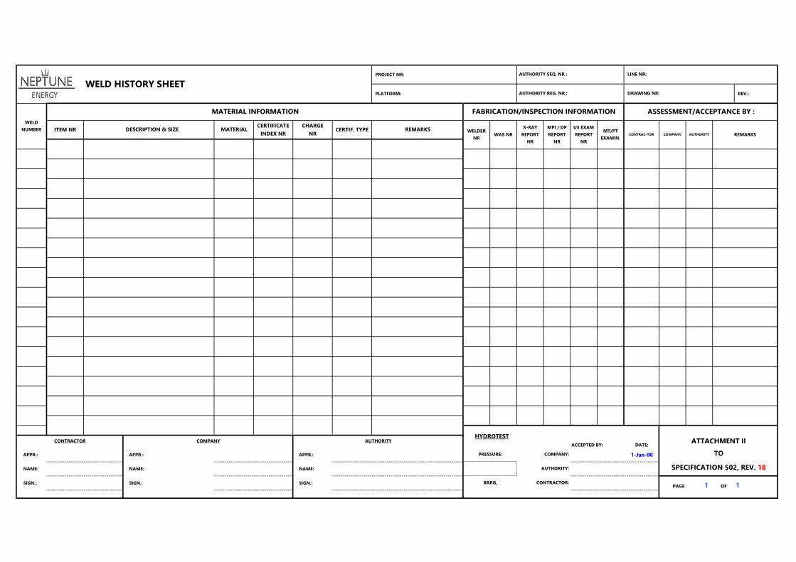
PROJECT NR:
PLATFORM: REV.:
ACCEPTED BY: DATE:
APPR.: APPR.: APPR.: 1-Jan-00
NAME: NAME: NAME:
SIGN.: SIGN.: SIGN.:PAGE 1 OF 1
CHARGE
NRCERTIF. TYPE REMARKS DESCRIPTION & SIZE
WAS NRWELDER
NR
MT/PT
EXAMIN.CONTRAC-TOR COMPANY AUTHORITY
X-RAY
REPORT
NR
AUTHORITY REG. NR :
MPI / DP
REPORT
NR
US EXAM
REPORT
NR
ATTACHMENT II
WELD
NUMBER ITEM NR MATERIALCERTIFICATE
INDEX NR
CONTRACTOR COMPANY AUTHORITY
FABRICATION/INSPECTION INFORMATION
TO
SPECIFICATION 502, REV. 18
DRAWING NR:
AUTHORITY SEQ. NR :
REMARKS
ASSESSMENT/ACCEPTANCE BY :
LINE NR:
MATERIAL INFORMATION
WELD HISTORY SHEET
HYDROTEST
PRESSURE:
BARG,
COMPANY:
AUTHORITY:
CONTRACTOR: