Embed Size (px)
Citation preview
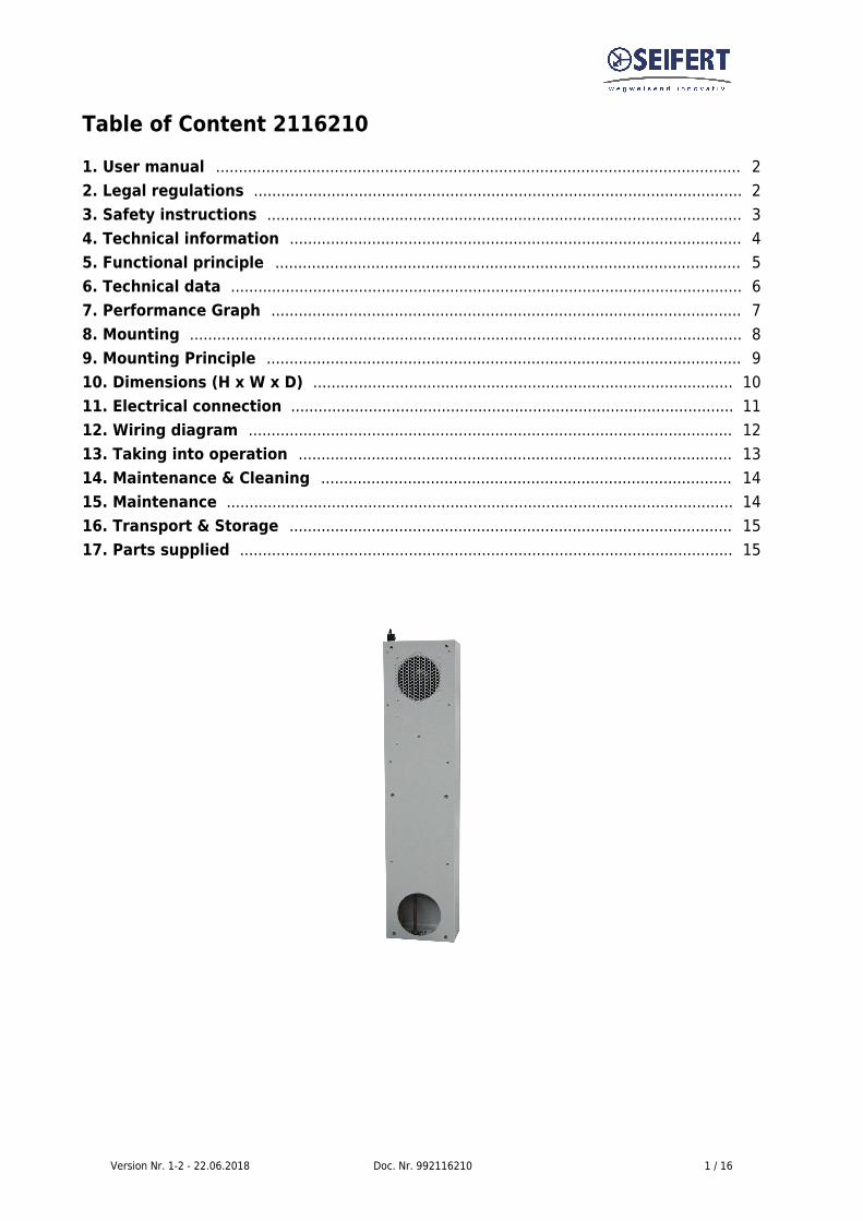
Version Nr. 1-2 - 22.06.2018 Doc. Nr. 992116210 1 / 16
Table of Content 21162101. User manual 2 ................................................................................................................... 2. Legal regulations 2 ........................................................................................................... 3. Safety instructions 3 ........................................................................................................ 4. Technical information 4 ................................................................................................... 5. Functional principle 5 ...................................................................................................... 6. Technical data 6 ................................................................................................................ 7. Performance Graph 7 ....................................................................................................... 8. Mounting 8 ......................................................................................................................... 9. Mounting Principle 9 ........................................................................................................ 10. Dimensions (H x W x D) 10 ............................................................................................ 11. Electrical connection 11 ................................................................................................. 12. Wiring diagram 12 .......................................................................................................... 13. Taking into operation 13 ............................................................................................... 14. Maintenance & Cleaning 14 .......................................................................................... 15. Maintenance 14 ............................................................................................................... 16. Transport & Storage 15 ................................................................................................. 17. Parts supplied 15 ............................................................................................................
Version Nr. 1-2 - 22.06.2018 Doc. Nr. 992116210 2 / 16
1. User manualThis instruction manual contains information and instructions to enable the user to work safely,correctly and economically on the unit. Understanding and adhering to the manual can help one:
Avoid any dangers.●
Reduce repair costs and stoppages.●
Extend and improve the reliability and working life of the unit.●
PLEASE ENSURE TO USE THE RIGHT VERSION OF THE INSTRUCTION MANUAL SUITABLE FORYOUR UNIT.
Conditions of useThe unit is to be used exclusively for the dissipation of heat from control cabinets and enclosures inorder to protect temperature sensitive components in an industrial environment. To meet theconditions of use, all the information and instructions in the instruction manual must be adhered to.
General dangerIndicates compulsory safety regulations which are notcovered by a specific pictogram such as one of the following. High electric voltageIndicates electric shock danger.
Important safety instructionIndicates instructions for safe maintenance and operation ofthe unit. AttentionIndicates possible burns from hot components. AttentionIndicates possible damage to the unit.
InstructionIndicates possible danger to the environment.
2. Legal regulationsLiabilityThe information, data and instructions contained in this instruction manual are current at the time ofgoing to press. We reserve the right to make technical changes to the unit in the course of itsdevelopment. Therefore, no claims can be accepted for previously delivered units based on theinformation, diagrams or descriptions contained in this manual. No liability can be accepted fordamage and production caused by:
Version Nr. 1-2 - 22.06.2018 Doc. Nr. 992116210 3 / 16
Disregarding the instruction manual●
Operating error●
Inappropriate work on or with the unit●
The use of non-specified spare parts and accessories●
Unauthorised modifications or changes to the unit by the user or his personnel●
The supplier is only liable for errors and omissions as outlined in the guarantee conditions contained inthe main contractual agreement. Claims for damages on any grounds are excluded.
3. Safety instructionsUpon delivery the unit is already meeting current technical standards therefore it can be safely takeninto operation. Only trained specialists are allowed to work on the unit. Unauthorised personnel mustbe prohibited from working on the unit. Operating personnel must inform their superiors immediately ifany malfunction of the unit becomes apparent.Please note that before starting to work on or with the unit, a procedure must be carried out inside thecabinet on which the unit is to be mounted.Before commencing work inside the cabinet, the control cabinet manufacturer's instruction must beread with regards to:
Safety instructions.●
Instructions on taking the cabinet out of operation.●
Instructions on the prevention of unauthorised cabinet reconnection.●
The electric equipment meets the valid safety regulations. One can find dangerous voltages (above 50V AC or above 100 V DC)
Behind the control cabinet doors.●
On the power supply in the unit housing.●
The unit has to be fused according to the type plate and the wiring diagram, and must be protectedexternally from overloading and electrical faults via suitable protective devices such as ground faultprotection breakers.
Danger through incorrect work on the unitThe unit can only be installed and maintained by technical competent andqualified personnel, using only supplied material according to the suppliedinstructions.
Danger from electrical voltageOnly specialised personnel are allowed to maintain and clean the unit. Thepersonnel must ensure that for the duration of the maintenance and cleaning, theunit is disconnected from the electrical supply.AttentionDamage to the unit through the use of inappropriate cleaning materials. Please donot use aggressive cleaning material.
InstructionDamage to the environment through unauthorised disposal. All spare parts andassociated material must be disposed according to the environmental laws.
Version Nr. 1-2 - 22.06.2018 Doc. Nr. 992116210 4 / 16
4. Technical informationAir - water heat exchangers are intended as complementary accessories to large industrial equipmentwhich include a motor-operated fan or blower together with a cooling heat exchanger. These may alsoinclude an electric heater. The fan or blower is intended to recirculate air and allow heat exchange.The heat exchanger is designed for chilled water or anti-freeze/corrosion inhibitor mixed water from aseparate source.The cooling function may be controlled by an on-board or remote controller or thermostat, athermostatically controlled valve or an electrically controlled valve. Heating function, when installed isprovided by an electrical heating element. The unit seals the cabinet which ensures that the clean airinside does not come into contact with the ambient air which may well be dirty or polluted. The unit isfit for purpose within the rated/declared ambient conditions (e.g. dusty and oily air or high airtemperatures between 1°C and 72°C), also indicating the rated allowable ingress and environment.
Water qualityTo ensure the maximum lifetime of an air-water heat exchangers, it is important to supply coolingwater in conformity with the VGB Cooling Water Guidelines (VGB-R 455 P). The cooling water usedmust be soft enough to avoid scale deposits, but should not be too soft as this would corrode the heatexchanger. Where the cooling water is cooled for reuse, part of the water has to be changed with freshwater to prevent the concentration of hardness and salt content which makes the water morecorrosive.The main impurities and possible methods of eliminating them are given in the table below:
Pollution of the water Method of eliminationMechanical impurities (dp > 2mm) Filtration of the waterExcessive hardness Softening of the water by ion
exchangeModerate content of mechanical impuritiesand hardness formers Addition of dispersants or stabilisersModerate content of chemical impurities Addition of passivators and inhibitorsBiological impurities (bacteria and algae) Addition of biocides
When the water is re-cooled, it is recommended that the water condition is maintained as close aspossible to the following list of hydrological data:
Hydrological data pH-values 7 - 8.5 Carbonate hardness >3 <8 °dHFree carbon dioxide 8 - 15 mg/dm³Associated carbon dioxide 8 - 15 mg/dm³Aggressive carbon dioxide 0 mg/dm³Sulphides free mg/dm³Oxygen < 10 mg/dm³Chloride ions < 50 mg/dm³Sulphate ions < 250 mg/dm³Nitrates and nitrites < 10 mg/dm³COB < 7 mg/dm³Ammonia < 5 mg/dm³Iron < 0.2 mg/dm³Manganese < 0.2 mg/dm³Conductivity < 2200 µS/cmSolid residue from evaporation < 500 mg/dm³
Version Nr. 1-2 - 22.06.2018 Doc. Nr. 992116210 5 / 16
Potassium manganate consumption < 25 mg/dm³Suspended matter < 3 mg/dm³(part flow cleaning recommended) > 3 < 15 mg/dm³(continuous cleaning) > 15 mg/dm³
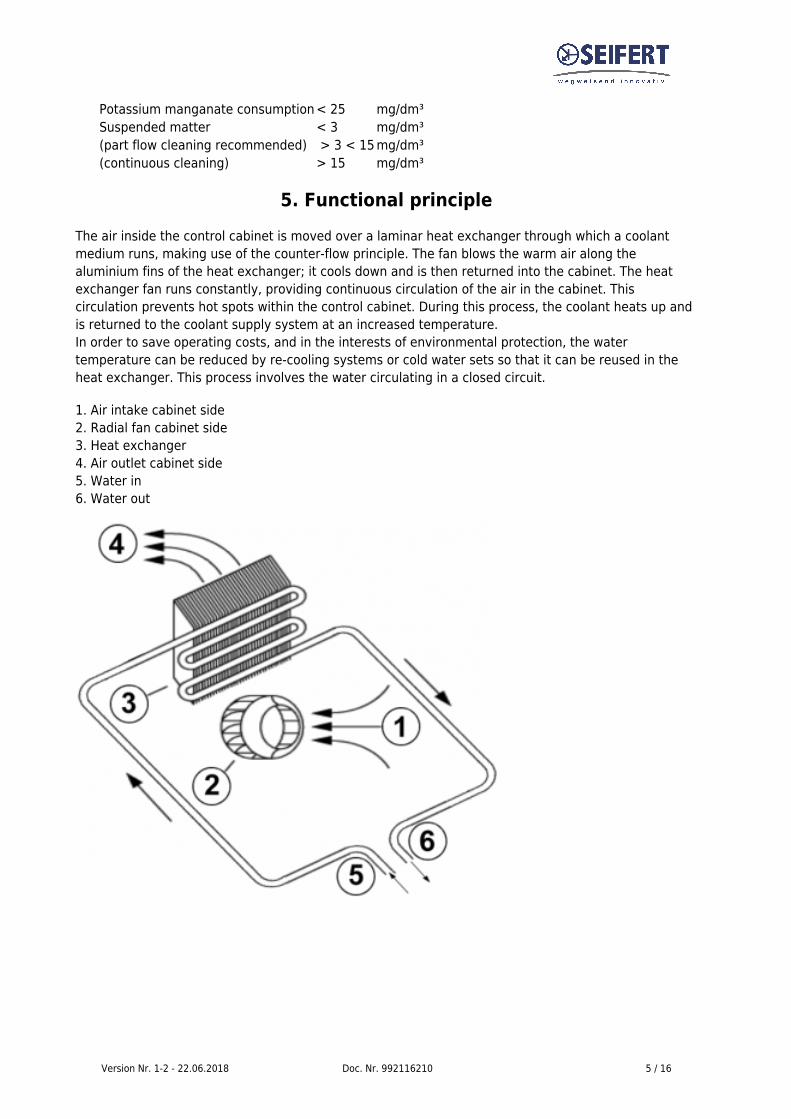
5. Functional principleThe air inside the control cabinet is moved over a laminar heat exchanger through which a coolantmedium runs, making use of the counter-flow principle. The fan blows the warm air along thealuminium fins of the heat exchanger; it cools down and is then returned into the cabinet. The heatexchanger fan runs constantly, providing continuous circulation of the air in the cabinet. Thiscirculation prevents hot spots within the control cabinet. During this process, the coolant heats up andis returned to the coolant supply system at an increased temperature.In order to save operating costs, and in the interests of environmental protection, the watertemperature can be reduced by re-cooling systems or cold water sets so that it can be reused in theheat exchanger. This process involves the water circulating in a closed circuit.
1. Air intake cabinet side2. Radial fan cabinet side3. Heat exchanger4. Air outlet cabinet side5. Water in6. Water out
Version Nr. 1-2 - 22.06.2018 Doc. Nr. 992116210 6 / 16
6. Technical data
Order Number 2116210Cooling capacity L35W10 (200 l/h) 2,1 kWCooling capacity L35W10 (500 l/h) 2,2 kWRefrigerant / GWP Water, light oils or similarTemperature range +1°C - +72°CAir volume flow 270 m³/h @ 50 Hz
300 m³/h @ 50 HzMounting Internal / ExternalHousing Material Mild steel, powder coatedDimension HxWxD 891 x 212 x 105 mmWeight 11.5 kgVoltage / Frequency 400 V - 50 Hz 3~
460 V - 60 Hz 3~Starting current 0.8 AMax. current 0.4 AMax. power 80 WPressure water circuit 10 barWater connection Rp 1/4" - inside thread with 2 connectors
for pipe internal diameter of 10mmFuse 3 x 1 A (T)Connection 3 m cable ready for connectionIP class EN 60529 IP 54Approvals CE, cURus, RoHS
Version Nr. 1-2 - 22.06.2018 Doc. Nr. 992116210 7 / 16
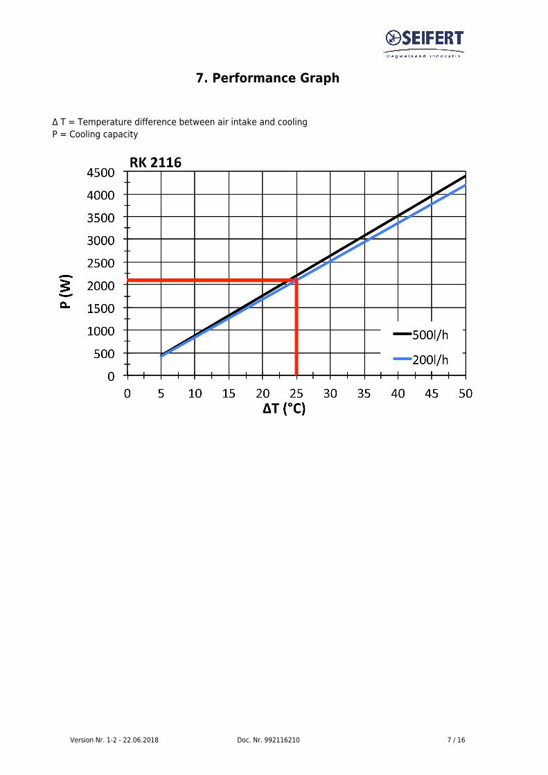
7. Performance Graph
Δ T = Temperature difference between air intake and coolingP = Cooling capacity
Version Nr. 1-2 - 22.06.2018 Doc. Nr. 992116210 8 / 16
8. MountingSeifert heat exchangers have an extremely compact design and construction, giving them theadvantage of occupying very little space. In addition, the RK-2114 A/AM, RK-2114 A/AM 632 and RK-2116 A/AM models can be mounted externally or internally, as required.To achieve a good seal between the control cabinet and the heat exchanger, the unit's mountingsurface on the control cabinet may need to be reinforced. The air intake and outlet must not beobstructed by equipment inside the control cabinet, so that the air is mixed thoroughly and thermalstratification is avoided.For the heat exchanger to work perfectly, the cabinet must be completely sealed from itssurroundings. An imperfectly sealed control cabinet will result in an increased level of condensation.The control cabinet should have a minimum of IP54 protection, in accordance with IEC 60 529.
Use of the mounting templateThe mounting template enables the unit to be installed quickly. For mounting the template should beattached to the wall of the cabinet and the holes for the fixing screws should be drilled in the wall ofthe cabinet in the marked positions.
Cooling medium connectionThere are two pipe connection points on the bottom (RK-2114, RK-2116, RK-2140) or in the side (RK-2124) of the unit to connect the refrigerant supply. The piping used for the supply must have aninternal diameter of 10 mm or 13 mm depending on the model. The pipe connectors have a ¼” thread(1/2" RK 2125948 / RK 21259500 / RK 2149) and can be replaced with other connectors for larger orsmaller pipe diameters. Before connecting the coolant circuit, note the flow direction of the coolantmedium. Next to the pipe connectors, the letters “E” and “A” are visible on the unit.
E coolant intakeA coolant outflow
To empty the unit connect the water inlet pipe to a compressed air supply and route the water outletpipe to a location where the water can be drained. Set the thermostatic head inside the unit to a set-point lower than ambient temperature to ensure it opens and slowly open the compressed air supplytill all the water in the heat exchanger is flushed out. Ensure that the pressure of the system is belowthe rated pressure of the unit and fitting.
Version Nr. 1-2 - 22.06.2018 Doc. Nr. 992116210 9 / 16
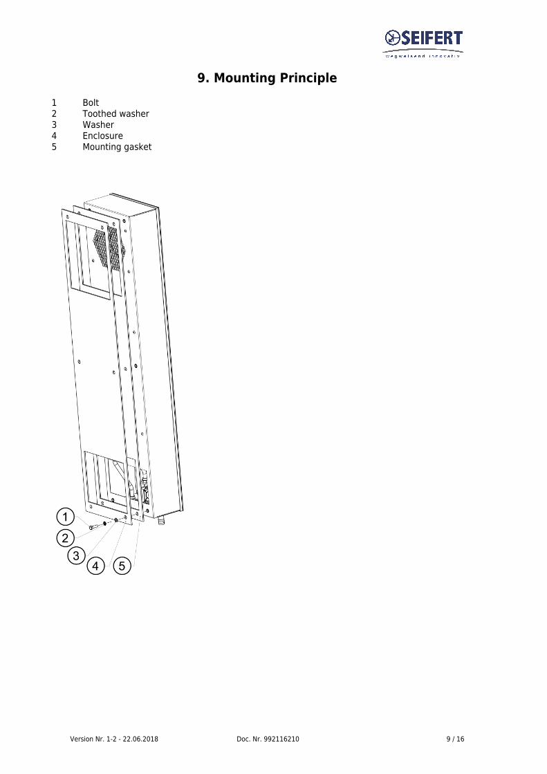
9. Mounting Principle1 Bolt2 Toothed washer3 Washer4 Enclosure5 Mounting gasket
Version Nr. 1-2 - 22.06.2018 Doc. Nr. 992116210 10 / 16
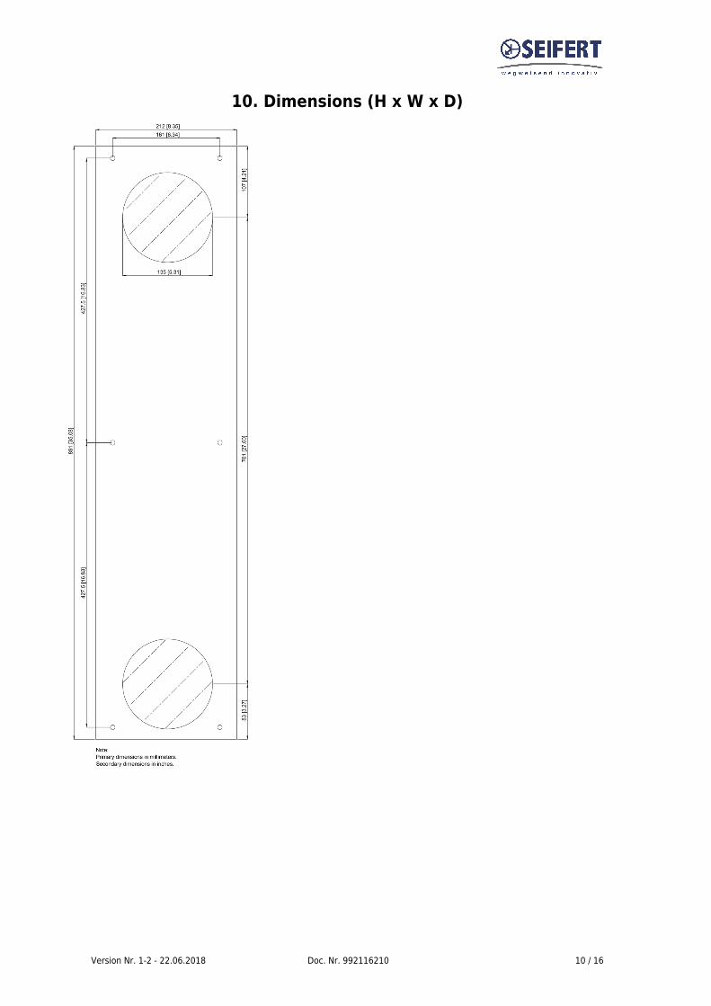
10. Dimensions (H x W x D)
Version Nr. 1-2 - 22.06.2018 Doc. Nr. 992116210 11 / 16
11. Electrical connection
High electric voltage present. Installation, maintenance, cleaning andany other work must be carried out by qualified personnel only. Thepersonnel must ensure that for the duration of this work the unit andthe cabinet are disconnected from the electrical supply and protectedagainst unauthorised/accidental reconnection.
Connection to the main electrical supply
The mains connection is made via a 3m cable ready for connection. To connect the unit tothe mains proceed as follows:
Take the control cabinet out of operation in the prescribed manner.●
See the connection details on the circuit diagram.●
Note the connections on the connector / terminal block from the following table●
Terminal 400V 3~L1 Phase (black)L2 Phase (blue)L3 Phase (brown)PE Protection- Earth (green / yellow)
Ensure that the correct polarity is maintained. The fans should haveclockwise rotation.
Connect the unit to the mains.●
Take the control cabinet back into operation in the prescribed manner.●
Power consumption and start-up current are stated on the data label and under technical data.●
Version Nr. 1-2 - 22.06.2018 Doc. Nr. 992116210 12 / 16
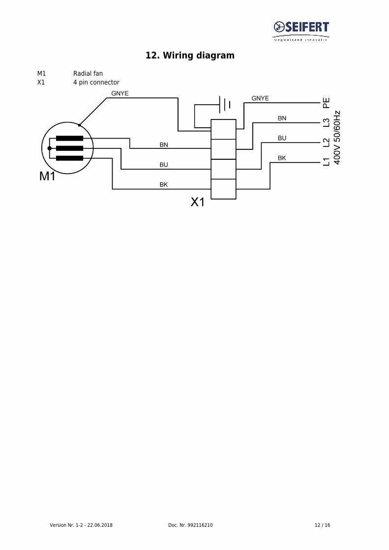
12. Wiring diagramM1 Radial fanX1 4 pin connector
Version Nr. 1-2 - 22.06.2018 Doc. Nr. 992116210 13 / 16
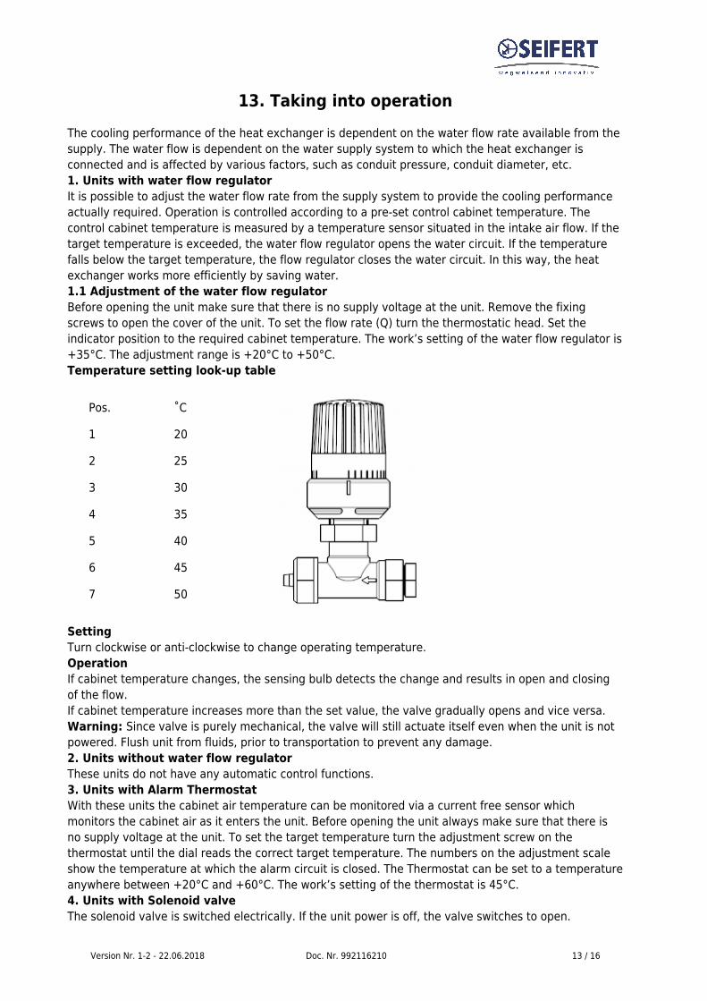
13. Taking into operationThe cooling performance of the heat exchanger is dependent on the water flow rate available from thesupply. The water flow is dependent on the water supply system to which the heat exchanger isconnected and is affected by various factors, such as conduit pressure, conduit diameter, etc.1. Units with water flow regulator It is possible to adjust the water flow rate from the supply system to provide the cooling performanceactually required. Operation is controlled according to a pre-set control cabinet temperature. Thecontrol cabinet temperature is measured by a temperature sensor situated in the intake air flow. If thetarget temperature is exceeded, the water flow regulator opens the water circuit. If the temperaturefalls below the target temperature, the flow regulator closes the water circuit. In this way, the heatexchanger works more efficiently by saving water.1.1 Adjustment of the water flow regulatorBefore opening the unit make sure that there is no supply voltage at the unit. Remove the fixingscrews to open the cover of the unit. To set the flow rate (Q) turn the thermostatic head. Set theindicator position to the required cabinet temperature. The work’s setting of the water flow regulator is+35°C. The adjustment range is +20°C to +50°C.Temperature setting look-up table
Pos. ˚C
1 20
2 25
3 30
4 35
5 40
6 45
7 50
SettingTurn clockwise or anti-clockwise to change operating temperature.OperationIf cabinet temperature changes, the sensing bulb detects the change and results in open and closingof the flow.If cabinet temperature increases more than the set value, the valve gradually opens and vice versa.Warning: Since valve is purely mechanical, the valve will still actuate itself even when the unit is notpowered. Flush unit from fluids, prior to transportation to prevent any damage.2. Units without water flow regulatorThese units do not have any automatic control functions.3. Units with Alarm ThermostatWith these units the cabinet air temperature can be monitored via a current free sensor whichmonitors the cabinet air as it enters the unit. Before opening the unit always make sure that there isno supply voltage at the unit. To set the target temperature turn the adjustment screw on thethermostat until the dial reads the correct target temperature. The numbers on the adjustment scaleshow the temperature at which the alarm circuit is closed. The Thermostat can be set to a temperatureanywhere between +20°C and +60°C. The work’s setting of the thermostat is 45°C.4. Units with Solenoid valveThe solenoid valve is switched electrically. If the unit power is off, the valve switches to open.
Version Nr. 1-2 - 22.06.2018 Doc. Nr. 992116210 14 / 16
5. Units with temperature controllerThe unit is equipped with a temperature controller which regulates the function of the unit. On normalworking conditions the display shows the temperature inside the enclosure. The controller “set point”for the interior of the enclosure (parameter St / St1) is pre-set at 35°C and can be adjusted between+20°C and +50°C.The High temperature alarm (parameter AH) is preset at 55°C. The High Temperature Alarm relay isdelivered as “normally closed” (H1=1). If you need to change it to “normally open”, please modifyvalue of parameter H1 (H1=2).
Modifying controller parameters1. Press the SET button for more than 3 sec. (if there are active alarms, mute the buzzer).The displayshows the parameter code ‘PS’ (password).2. Only for parameters requiring password: Press the SET button to access the password setting, usethe UP and DOWN buttons to scroll the numbers until displaying, “22” (default password to access theparameters), press the SET button to confirm the password3. Use the UP and DOWN buttons to scroll the parameters. The LED corresponding to the category ofparameters will be on4. Press SET to display the value associated with the parameter5. Increase or decrease the value using the UP or DOWN button respectively6. Press SET to temporarily save the new value7. Press the SET button for more than 3 sec. to permanently save the new parameters and exit theparameter setting procedure.
If no button is pressed for 60 sec. all changes made to the parameters, temporarily saved in the RAM,will be cancelled and the previous settings restored. The cooling unit manufacturer is in no way liablefor any alterations the customer may make to the factory set parameters, unless the manufacturer hasauthorized the customer in writing to change them.
This manual is intended as quick reference for controller, for a full controller manual or if you need torestore the factory parameters please go to our website to download the full manual or to locate yournearest servicing office.
6. Units with door switchThe unit can be switched on and of via a door contact switch (optional). When delivered the doorcontact terminals are bridged on the female connector. To connect the door contact switch remove thebridge and connect door contact switch. The contact must be closed when the cabinet door is closed.
14. Maintenance & CleaningThe unit should have regular functional tests (approx. every 2,000 hours depending on the grade ofambient pollution).
15. MaintenanceEvery unit is given a performance test under load at the factory. The units are largely maintenance-free, however, the following points should be observed:
1. Fan replacementBefore replacing the fan, the equipment must be switched off from the power supply (pull out mainsplug or connecting cable). The rated life time of the fan is L10 = 30.000 hours under normaloperational conditions. Should it become necessary to replace the fan, remove the support for the fanby loosening the 4 fastening screws (RK-2114 models only). To detach the fan from the fan supportloosen a further 4 screws and the fan connecting cable.
Version Nr. 1-2 - 22.06.2018 Doc. Nr. 992116210 15 / 16
When connecting the new fan, take care that the correct polarity is maintained.
2.Thermostat replacement Before replacing the thermostat, isolate the equipment from the power supply (pull out mains plug orconnecting cable). Detach the thermostat from its support by unclipping it from the DIN railing andloosening the 4 connecting cables.When connecting the new fan make sure that the correct polarity is maintained.
3. Environmental protectionIf the heat exchanger has reached its end of life state, we will dispose it if it is returned to us freightpaid.
4. Maintenance work on the cooling circuitAll the maintenance operations described above should only be carried out by expert personnel. Allwork on the cooling circuit should only be carried out at the factory.
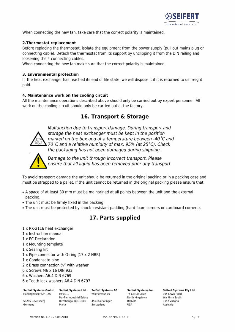
16. Transport & StorageMalfunction due to transport damage. During transport andstorage the heat exchanger must be kept in the positionmarked on the box and at a temperature between -40˚C and70˚C and a relative humidity of max. 95% (at 25°C). Checkthe packaging has not been damaged during shipping. Damage to the unit through incorrect transport. Pleaseensure that all liquid has been removed prior any transport.
To avoid transport damage the unit should be returned in the original packing or in a packing case andmust be strapped to a pallet. If the unit cannot be returned in the original packing please ensure that:
A space of at least 30 mm must be maintained at all points between the unit and the external●
packing.The unit must be firmly fixed in the packing.●
The unit must be protected by shock -resistant padding (hard foam corners or cardboard corners).●
17. Parts supplied1 x RK-2116 heat exchanger1 x Instruction manual1 x EC Declaration1 x Mounting template1 x Sealing kit1 x Pipe connector with O-ring (17 x 2 NBR)1 x Condensate pipe2 x Brass connection ¼” with washer6 x Screws M6 x 16 DIN 9336 x Washers A6.4 DIN 67696 x Tooth lock washers A6.4 DIN 6797
Seifert Systems GmbH Seifert Systems Ltd. Seifert Systems AG Seifert Systems Inc. Seifert Systems Pty Ltd.Haßlinghauser Str. 156 HF09/10 Wilerstrasse 16 75 Circuit Drive 105 Lewis Road Hal-Far Industrial Estate North Kingstown Wantirna South58285 Gevelsberg Birzebbuga, BBG 3000 4563 Gerlafingen RI 0285 3152 VictoriaGermany Malta Switzerland USA Australia
Version Nr. 1-2 - 22.06.2018 Doc. Nr. 992116210 16 / 16
Tel. +49 (0) 2332 55124-0 Tel. +356 2220 7000 Tel. +41 (0) 32 675 35 51 Tel. +1 401-294-6960 Tel. +61 (3) 98 01 19 06Fax +49 (0) 2332 5512429 Fax +356 2165 2009 Fax +41 (0) 32 675 44 76 Fax +1 401-294-6963 Fax. +61 (3) 98 87 08 [email protected] [email protected] [email protected] [email protected] [email protected]


![Design Studio 3 [ARC 2116]](https://img.pdfslide.us/doc/110x75/568c34c31a28ab023591a944/design-studio-3-arc-2116.jpg)