Embed Size (px)
Citation preview


Table of Contents
EFP Introduction 4
Connector Features 5-7
Code Logic 8
Inline Plug w Threaded Entry Metric 9
Inline Plug w Mechanical Clamp 10
Inline Plug w Basket Weave Grip 11
Inline Plug w Compression Nut 12
Inline Receptacle w Threaded Entry 13
Inline Receptacle w Mechanical Clamp 14
Inline Receptacle w Basket Weave Grip 15
Inline Receptacle w Compression Nut 16
Panel Mount Receptacle 17
Panel Mount Receptacle w Threaded Entry 18
Panel Mount Receptacle w Mechanical Clamp 19
Panel Mount Receptacle w Basket Weave Grip 20
Panel Mount Receptacle w Compression Nut 21
EFP SERIESFLAMEPROOF ELECTRICAL CONNECTORS FOR HAZARDOUS ENVIRONMENTS


4
EFP SERIES INTRODUCTION
The EFP Series of electrical connectors is a comprehensive line of power, control and instrumentation electrical connectors products. This series is certified for use in hazardous locations (Class 1 / Zone 1)
EFP Series electrical connectors may be specified for use in Oil, Gas and Petro-Chemical applications, land based and offshore drilling systems and areas of application include power, control and instrumentation circuits
The connector bodies are manufactured from hard anodised aluminium, alternative materials such as brass and stainless steel, nickel aluminium bronze and titanium are also available.
EFP series connectors are designed for quick mating and unmating. Cable accommodations including armored and sheathed allow industrial, offshore, and petrochemical type cables to be terminated in various manners depending on cable type as well as application and regulatory requirements.
Receptacles are available for panel or cable 'inline' mounting. Receptacles with a potting adaptor can be installed into either an EEx 'd' flameproof, EEx 'e' increased safety. The contact termination methods available are solder, crimp or pressure termination depending on insert selection. Contact materials are copper alloys and various plating options are available depending on application and ampacity. Silver and gold plating, over copper contacts are standard.
The EFP series lends itself to both single and multi conductor applications, with a comprehensive range of inserts to suit wire size 18 AWG (0.75mm2) to 1111 MCM (563mm2). Multipole power inserts are available up to 600 amperes at 1000V, Single pole power to 1135 amperes at 1000V. Control and instrumentation inserts are available in 2 through 143 contacts. Composite inserts (power & control) are also readily available.
For planned non intermateability connectors maybe furnished with alternate key positions and may be color coded for visual identification.
EFP Series connectors share common insert configurations with the HDS series of connectors, allowing for a complete systems integration in both hazardous and non hazardous locations.

5
CONNECTOR FEATURES OVERVIEWEFP SERIES
• Suitable for use in Zone 1, ATEX, IECEx, and NEC • Suitable for use in Gas Groups IIA, IIB and IIC • Ingress Protection of IP68 to IEC60529 with deluge protection to DTS01:91 • Operating Temperature range -55° to +125°C. Temperature Class & Ambient T5 40°C • Optional T5 and T6 temperature classifications are available with ambient's up to 65°C
Panel-mounted receptacle may aslo be fitted to Ex e (increased safety) certified equipment
Threaded Protective Cover achieves IP68 Ingress Protection
Multi and Single Pin insert options. Available for reverse service
Heavy Duty Coupling Nut
Knurled section for assembly ease
Long Cable Adapter Allows ample space for ease of termination
Cable Entry OptionsAccepts Multiple cable types depending on application and termination method

6
EFP CONNECTOR FEATURES
Keyed PositionsProvides an extended installation keyway, which assists connector assembly by making Pin and Socket insertion quick and easy and integrating mold into the insert guarentees alignment while preventing pin damage.
Threaded Bulkhead ConnectorThe threaded bulkhead connector utilises industry standard threads and also incoprorates integral 'o' ring seal. Suitable for IIC locations, EFP connectors can be supplied preterminated and encapsulated to suit the customer's requirements.
Multiple Keyway OptionThe unique multi position insert keying system along with the integral machined keyways prevent contact damage and ensures safe use by eliminating the possibility of misconnection of adjacent circuits.
Multi Armor ConeThe EFP incorporates our proven and patented armor termination method. Clamping devices are supplied to accomodate different types including SWA and braid.
Acme Thread at Mating InterfaceUnique ACME thread offers a strong and durable thread form in service. The thread is easy to start and less susceptible to jamming.
Flameproof Barrier JointA component carrier joint provides a flameproof method of protection with a low termpature rating of -55°C.

7
Versatile LSFZH Rear SealAccommodates a wide range of cable sizes and provides highly effective cable grip and ingress protectionI IP68.
Stainless Steel EFP Electrical ConnectorsEFP Electrical connectors are available from stock in shell sizes 12 through 28. The connectors are manufactured in a variety of stainless steel materials including but not limited to types 303, 304, 316L. All configurations available in the hard anodized variants are available in stainless steel.
EFP Cable AssembliesAll connector variants are available as complete cable assemblies whether the cable mounted variants of receptacles requirering leads. We are able to provid receptacle assembled and certified in accordance with the following protection concepts: Eex d, Eex e, Eex and P.
EX Series Cable Glands A2 Series cable glands are the perfect cable glad for the termination of offshore type cable. A straight forward design and good quality workmanship allow EEC to offer this gland for assembly on to cable mounted receptacles for protection classes Eex d and Eex e.
EFP CONNECTOR FEATURES

8
10 Color coding optionsBK BlackR RedW whiteBL BlueG GreenOR orangeY YellowB BrownP PurpleGY Gray
1 Connector Body MaterialB - BrassN - Nickel Aluminum BronzeS - StainlessT - TitaniumOmitted - Aluminum (STD.)
2 Shell Type13 - Plug15 - Inline Receptacle17 - Panel Mount Receptacle
3 Cable Adapter Styles1 Enclosure2# Mechanical Clamp*3# Threaded entry for Ex Gland4# Basket Weave grip*5# Compression nut*6 Panel Mount Adapter (Plug)*7 NPT Mount (Receptacle)*8 Junction Box 45*9 EZ Term
*Need to be back-potted#For Short Cable Adapter, add "S" after Cable Adapter Style
5 Shell Size121620, C2024, C2428, C28
6 Insert ArrangementSee Insert Section
7 Contact GenderM Male (Pin)F Female (Socket)LM or LF - Low Insertion Force Contact
8 Termination StyleS - SolderR - PressureOmitted - crimp
9 Insert OrientationOmitted - Normal (STD)Alternatives select from insert selection guide
11 VariationsWire or Cable length if factory assembled expressed in feet
Armor Style (omit if no armor)AR - Armored no SheathAS - Armored and Sheath
4 Sealing Method
Grommet I.D. 02 To 46 - Range Available (Multiples of 1/8” (0.125mm) i.e. 06=6/8” (0.75mm)Potting required (Stycast 2850), -55oC Hysol EE4183* or Approved cable gland Ex d or Ex e to suit cable construction 00 - Without gland, A2A to A2H for gland non-armored Section E1A to E1H
CODE LOGIC EFP SERIES
1EFP 3 3 A A A 1 1 12 2 6 0 1FR22 3 4 5 6 7 8 9 10 111

9
INLINE PLUG WITH THREADED ENTRY (METRIC)EFP-13-3-XX
A B C Tread D
5-3/4 (146.1)
7-3/4 (196.9)
7-3/4 (196.9)
7-3/4 (196.9)
7-3/4 (196.9)
3-1/16 (77.8)
3-1/16 (77.8)
3-1/16 (77.8)
3-1/16 (77.8)
3-1/16 (77.8)
2-1/4 (57.1)
2-3/4 (69.9)
3-1/4 (82.6)
3-3/4 (95.2)
4-1/4 (107.9)
M25x1.5-6H
M40x1.5-6H
M50x1.5-6H
M63x1.5-6H
M75x1.5-6H
Notes: For "C" length inserts, add 1/2" (12.7mm) to both dimensions "A" & "B".
Dimension
12
16
20
24
28
ShellSize
10
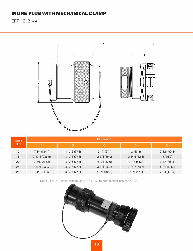
INLINE PLUG WITH MECHANICAL CLAMPEFP-13-2-XX
7-1/4 (184.1)
9-5/16 (236.5)
9-3/8 (238.1)
9-7/16 (239.7)
9-1/2 (241.3)
3-1/16 (77.8)
3-1/16 (77.8)
3-1/16 (77.8)
3-1/16 (77.8)
3-1/16 (77.8)
2-1/4 (57.1)
2-3/4 (69.9)
3-1/4 (82.6)
3-3/4 (95.2)
4-1/4 (107.9)
2 (50.8)
2-1/16 (52.4)
2-1/8 (54.0)
2-3/16 (55.6)
2-1/4 (57.2)
2-3/8 (60.3)
3 (76.2)
3-3/4 (95.3)
4-1/2 (114.3)
5-1/8 (130.2)
Notes: For "C" length inserts, add 1/2" (12.7) to both dimensions "A" & "B".
12
16
20
24
28
A B C D E
DimensionShellSize
11
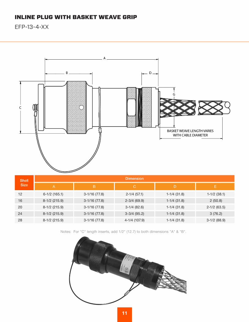
INLINE PLUG WITH BASKET WEAVE GRIPEFP-13-4-XX
Notes: For "C" length inserts, add 1/2" (12.7) to both dimensions "A" & "B".
A B C D E
DimensionShellSize
6-1/2 (165.1)
8-1/2 (215.9)
8-1/2 (215.9)
8-1/2 (215.9)
8-1/2 (215.9)
3-1/16 (77.8)
3-1/16 (77.8)
3-1/16 (77.8)
3-1/16 (77.8)
3-1/16 (77.8)
2-1/4 (57.1)
2-3/4 (69.9)
3-1/4 (82.6)
3-3/4 (95.2)
4-1/4 (107.9)
1-1/4 (31.8)
1-1/4 (31.8)
1-1/4 (31.8)
1-1/4 (31.8)
1-1/4 (31.8)
1-1/2 (38.1)
2 (50.8)
2-1/2 (63.5)
3 (76.2)
3-1/2 (88.9)
12
16
20
24
28

12
INLINE PLUG WITH COMPRESSION NUTEFP-13-5-XX
Notes: For "C" length inserts, add 1/2" (12.7mm) to both dimensions "A" & "B".
A B C D E
DimensionShellSize
6-1/2 (165.1)
8-1/2 (215.9)
8-1/2 (215.9)
8-1/2 (215.9)
8-1/2 (215.9)
3-1/16 (77.8)
3-1/16 (77.8)
3-1/16 (77.8)
3-1/16 (77.8)
3-1/16 (77.8)
2-1/4 (57.1)
2-3/4 (69.9)
3-1/4 (82.6)
3-3/4 (95.2)
4-1/4 (107.9)
1-1/4 (31.8)
1-1/4 (31.8)
1-1/4 (31.8)
1-1/4 (31.8)
1-1/4 (31.8)
1-1/2 (38.1)
2 (50.8)
2-1/2 (63.5)
3 (76.2)
3-1/2 (88.9)
12
16
20
24
28

13
INLINE RECEPTACLE WITH THREADED ENTRYEFP-15-3-XX
Notes: For "C" length inserts, add 1/2" (12.7) to both dimensions "A" & "B".
A B C Tread D
DimensionShellSize
6-1/8 (155.6)
8-1/8 (206.4)
8-1/8 (206.4)
8-1/8 (206.4)
8-1/8 (206.4)
1-1/2 (38.1)
1-1/2 (38.1)
1-1/2 (38.1)
1-1/2 (38.1)
1-1/2 (38.1)
1-1/2 (38.1)
2 (50.8)
2-1/2 (63.5)
3 (76.2)
3-1/2 (88.9)
M25x1.5-6H
M40x1.5-6H
M50x1.5-6H
M63x1.5-6H
M75x1.5-6H
12
16
20
24
28
14
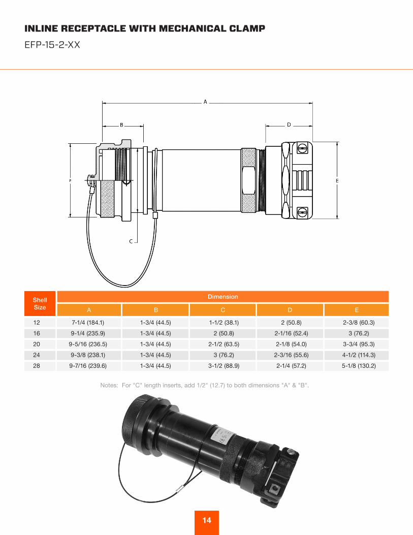
INLINE RECEPTACLE WITH MECHANICAL CLAMPEFP-15-2-XX
A B C D E
DimensionShellSize
7-1/4 (184.1)
9-1/4 (235.9)
9-5/16 (236.5)
9-3/8 (238.1)
9-7/16 (239.6)
1-3/4 (44.5)
1-3/4 (44.5)
1-3/4 (44.5)
1-3/4 (44.5)
1-3/4 (44.5)
1-1/2 (38.1)
2 (50.8)
2-1/2 (63.5)
3 (76.2)
3-1/2 (88.9)
2 (50.8)
2-1/16 (52.4)
2-1/8 (54.0)
2-3/16 (55.6)
2-1/4 (57.2)
2-3/8 (60.3)
3 (76.2)
3-3/4 (95.3)
4-1/2 (114.3)
5-1/8 (130.2)
12
16
20
24
28
Notes: For "C" length inserts, add 1/2" (12.7) to both dimensions "A" & "B".

15
INLINE RECEPTACLE WITH BASKET WEAVE GRIPEFP-15-4-XX
A B C D E
DimensionShellSize
6-1/2 (165.1)
8-1/2 (215.9)
8-1/2 (215.9)
8-1/2 (215.9)
8-1/2 (215.9)
1-3/4 (44.5)
1-3/4 (44.5)
1-3/4 (44.5)
1-3/4 (44.5)
1-3/4 (44.5)
1-1/2 (38.1)
2 (50.8)
2-1/2 (63.5)
3 (76.2)
3-1/2 (88.9)
1-1/4 (31.8)
1-1/4 (31.8)
1-1/4 (31.8)
1-1/4 (31.8)
1-1/4 (31.8)
1-1/2 (38.1)
2 (50.8)
2-1/2 (63.5)
3 (76.2)
3-1/2 (88.9)
12
16
20
24
28
Notes: For "C" length inserts, add 1/2" (12.7) to both dimensions "A" & "B".
16
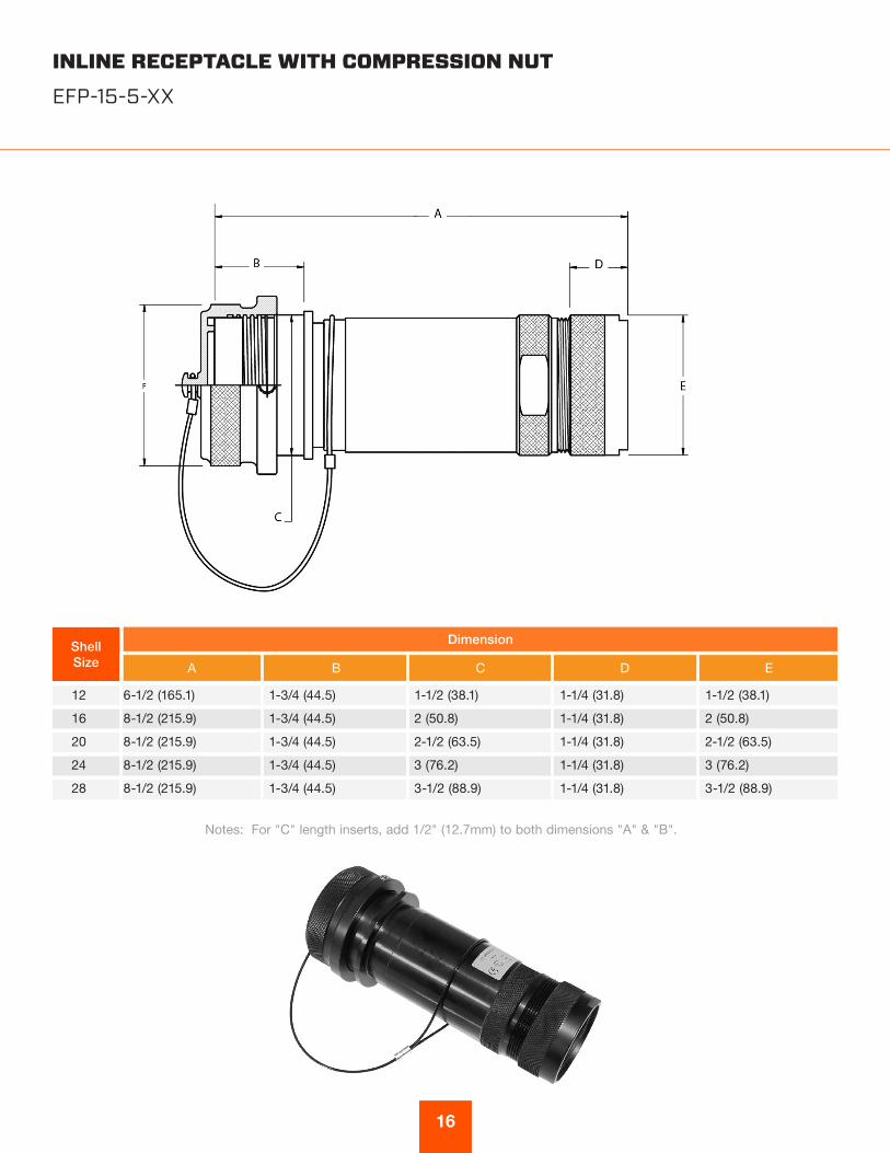
INLINE RECEPTACLE WITH COMPRESSION NUTEFP-15-5-XX
A B C D E
ShellSize
6-1/2 (165.1)
8-1/2 (215.9)
8-1/2 (215.9)
8-1/2 (215.9)
8-1/2 (215.9)
1-3/4 (44.5)
1-3/4 (44.5)
1-3/4 (44.5)
1-3/4 (44.5)
1-3/4 (44.5)
1-1/2 (38.1)
2 (50.8)
2-1/2 (63.5)
3 (76.2)
3-1/2 (88.9)
1-1/4 (31.8)
1-1/4 (31.8)
1-1/4 (31.8)
1-1/4 (31.8)
1-1/4 (31.8)
1-1/2 (38.1)
2 (50.8)
2-1/2 (63.5)
3 (76.2)
3-1/2 (88.9)
12
16
20
24
28
Notes: For "C" length inserts, add 1/2" (12.7mm) to both dimensions "A" & "B".
Dimension

17
PANEL MOUNT RECEPTACLEEFP-17-1-XX
A B C D E F G
DimensionShellSize
4-3/4 (120.7)
4-3/4 (120.7)
4-3/4 (120.7)
4-3/4 (120.7)
4-3/4 (120.7)
1-3/4 (44.5)
1-3/4 (44.5)
1-3/4 (44.5)
1-3/4 (44.5)
1-3/4 (44.5)
1-1/2 (38.1)
2 (50.8)
2-1/2 (63.5)
3 (76.2)
3-1/2 (88.9)
1.654 (42)
2.047 (52)
2.441 (62)
2.835 (72)
3.228 (82)
2-1/4 (57.2)
2-5/8 (66.7)
3 (76.2)
3-1/2 (88.9)
4 (101.6)
3-3/8 (86)
3-7/8 (98)
4-5/8 (118)
5-1/8 (130)
5-5/8 (143)
M40x1.5 -6g
M50x1.5 -6g
M63x1.5 -6g
M75x1.5 -6g
M90x1.5 -6g
12
16
20
24
28
Notes: For "C" length inserts, add 1/2" (12.7) to both dimensions "A" & "B".

18
PANEL MOUNT RECEPTACLE WITH THREADED ENTRY (METRIC)EFP-17-3-XX
A B C D E Thread F
ShellSize
5-7/8 (150)
7-7/8 (200)
7-7/8 (200)
7-7/8 (200)
7-7/8 (200)
1-3/4 (44.5)
1-3/4 (44.5)
1-3/4 (44.5)
1-3/4 (44.5)
1-3/4 (44.5)
1-1/2 (38.1)
2 (50.8)
2-1/2 (63.5)
3 (76.2)
3-1/2 (88.9)
1.654 (42)
2.047 (52)
2.441 (62)
2.835 (72)
3.228 (82)
2-1/4 (57.2)
2-5/8 (66.7)
3 (76.2)
3-1/2 (88.9)
4 (101.6)
M25x1.5-6H
M40x1.5-6H
M50x1.5-6H
M63x1.5-6H
M75x1.5-6H
12
16
20
24
28
Notes: For "C" length inserts, add 1/2" (12.7mm) to both dimensions "A" & "B".
Dimension

19
PANEL MOUNT RECEPTACLE WITH MECHANICAL CLAMPEFP-17-2-XX
A B C D E F G
DimensionShellSize
7-1/4 (184.1)
9-1/4 (235.9)
9-5/16 (236.5)
9-3/8 (238.1)
9-7/16 (239.6)
1-3/4 (44.5)
1-3/4 (44.5)
1-3/4 (44.5)
1-3/4 (44.5)
1-3/4 (44.5)
1-1/2 (38.1)
2 (50.8)
2-1/2 (63.5)
3 (76.2)
3-1/2 (88.9)
1.654 (42)
2.047 (52)
2.441 (62)
2.835 (72)
3.228 (82)
2-1/4 (57.2)
2-5/8 (66.7)
3 (76.2)
3-1/2 (88.9)
4 (101.6)
2 (50.8)
2-1/16 (52.4)
2-1/8 (54.0)
2-3/16 (55.6)
2-1/4 (57.2)
2-3/8 (60.3)
3 (76.2)
3-3/4 (95.3)
4-1/2 (114.3)
5-1/8 (130.2)
12
16
20
24
28
Notes: For "C" length inserts, add 1/2" (12.7) to both dimensions "A" & "B".
20
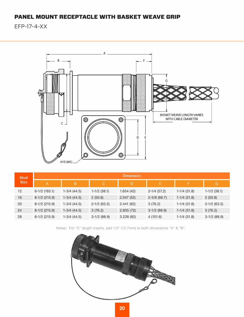
PANEL MOUNT RECEPTACLE WITH BASKET WEAVE GRIPEFP-17-4-XX
Notes: For "C" length inserts, add 1/2" (12.7mm) to both dimensions "A" & "B".
A B C D E F G
DimensionShellSize
6-1/2 (165.1)
8-1/2 (215.9)
8-1/2 (215.9)
8-1/2 (215.9)
8-1/2 (215.9)
1-3/4 (44.5)
1-3/4 (44.5)
1-3/4 (44.5)
1-3/4 (44.5)
1-3/4 (44.5)
1-1/2 (38.1)
2 (50.8)
2-1/2 (63.5)
3 (76.2)
3-1/2 (88.9)
1.654 (42)
2.047 (52)
2.441 (62)
2.835 (72)
3.228 (82)
2-1/4 (57.2)
2-5/8 (66.7)
3 (76.2)
3-1/2 (88.9)
4 (101.6)
1-1/4 (31.8)
1-1/4 (31.8)
1-1/4 (31.8)
1-1/4 (31.8)
1-1/4 (31.8)
1-1/2 (38.1)
2 (50.8)
2-1/2 (63.5)
3 (76.2)
3-1/2 (88.9)
12
16
20
24
28
21
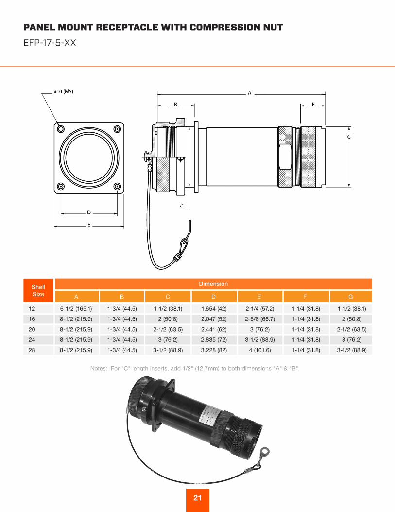
PANEL MOUNT RECEPTACLE WITH COMPRESSION NUTEFP-17-5-XX
A B C D E F G
DimensionShellSize
6-1/2 (165.1)
8-1/2 (215.9)
8-1/2 (215.9)
8-1/2 (215.9)
8-1/2 (215.9)
1-3/4 (44.5)
1-3/4 (44.5)
1-3/4 (44.5)
1-3/4 (44.5)
1-3/4 (44.5)
1-1/2 (38.1)
2 (50.8)
2-1/2 (63.5)
3 (76.2)
3-1/2 (88.9)
1.654 (42)
2.047 (52)
2.441 (62)
2.835 (72)
3.228 (82)
2-1/4 (57.2)
2-5/8 (66.7)
3 (76.2)
3-1/2 (88.9)
4 (101.6)
1-1/4 (31.8)
1-1/4 (31.8)
1-1/4 (31.8)
1-1/4 (31.8)
1-1/4 (31.8)
1-1/2 (38.1)
2 (50.8)
2-1/2 (63.5)
3 (76.2)
3-1/2 (88.9)
12
16
20
24
28
Notes: For "C" length inserts, add 1/2" (12.7mm) to both dimensions "A" & "B".

22
Amphenol EEC offers an extensive line of explosion-proof and general duty cable glands. Consult Amphenol Industrial Operations and ask for new catalog 12-055, Amphenol Cable Glands and Cord Grips.
EEX D CABLE TYPES / CABLE GLAND
EEx d Cable GLand Size
Code
Unarmored Cable No deviation if Unarmored
Armored & Sheathed Cable Armored & Sheathed
with reduced bore
UA Standard OD-Reduced
Min Max Min Max Min Max Min Max
A1 .1575 (4.0) .3307 (8.4) .1339 (3.4) .3307 (8.4) .3543 (9.0) .5315 (13.5) .2638 (6.7) .4055 (10.3)
A2 .2835 (7.2) .4606 (11.7) .2835 (7.2) .4606 (11.7) .4528 (11.5) .6299 (16.0) .3701 (9.4) .4921 (12.5)
A .3780 (9.6) .5512 (14.0) .3701 (9.4) .5512 (14.0) .6102 (15.5) .8307 (21.1) .4724 (12.0) .6929 (17.6)
B .5315 (13.5) .7874 (20.0) .5315 (13.5) .7874 (20.0) .7992 (20.3) 1.079 (27.4) .6614 (16.8) .9409 (23.9)
C .7677 (19.5) 1.035 (26.3) .7677 (19.5) 1.035 (26.3) 1.051 (26.7) 1.339 (34.0) .9134 (23.2) 1.201 (30.5)
C2 .9055 (23.0) 1.268 (32.2) .9055 (23.0) 1.268 (32.2) 1.299 (33.0) 1.598 (40.6) 1.126 (28.6) 1.425 (36.2)
D 1.110 (28.2) 1.504 (38.2) 1.016 (28.1) 1.504 (38.2) 1.551 (39.4) 1.839 (46.7) 1.370 (34.8) 1.669 (42.4)
D2 1.307 (33.2) 1.736 (44.1) 1.303 (33.1) 1.736 (44.1) 1.799 (45.7) 2.094 (53.2) 1.618 (41.1) 1.909 (48.5)
E 1.547 (39.3) 1.972 (50.1) 1.543 (39.2) 1.969 (50.0) 2.051 (52.1) 2.343 (59.5) 1.870 (47.5) 2.157 (54.8)
E2 1.839 (46.7) 2.205 (56.0) 1.839 (46.7) 2.205 (56.0) 2.299 (58.4) 2.591 (65.8) 2.118 (53.8) 2.409 (61.2)
F 2.059 (52.3) 2.441 (62.0) 2.051 (52.1) 2.441 (62.0) 2.551 (64.8) 2.843 (72.2) 2.370 (60.2) 2.677 (68.0)
F2 2.287 (58.1) 2.677 (68.0 2.283 (58.0) 2.677 (68.0) 2.799 (71.1) 3.071 (78.0) 2.618 (66.5) 2.890 (73.4)
G 2.453 (62.3) 2.835 (72.0) 2.449 (62.2) 2.835 (72.0) 3.031 (77.0) 3.307 (84.0) - -