Embed Size (px)
Citation preview
Teledyne Continental Motors, Inc.
TM
Engine Installation
TSIO-550 Permold Series Engine Installation and Operation Manual 4-1 29 November 2006
Chapter 4. ENGINE INSTALLATION
CONTENTS
Chapter 4. Engine Installation.................................................................................................. 4-1
4-1. Materials Required for Engine Installation .......................................................................... 4-3
4-1.1. Common Tools and Consumable Supplies Required ................................................................................ 4-4 4-1.2. Special Tool and Material Vendors ........................................................................................................... 4-5
4-2. Engine Receipt and Handling ............................................................................................... 4-6
4-2.1. Uncrating the Engine ................................................................................................................................. 4-6 4-2.2. Crating an Engine for Shipping ................................................................................................................. 4-6 4-2.3. Acceptance Inspection ............................................................................................................................... 4-6 4-2.4. Engine Transport ....................................................................................................................................... 4-7
4-3. Installation Procedures ......................................................................................................... 4-7
4-3.1. Prepare the Airframe for Engine Installation............................................................................................. 4-7 4-3.2. Prepare the Engine for Installation ............................................................................................................ 4-7 4-3.3. Installation Sequence............................................................................................................................... 4-10 4-3.4. Installation Inspection.............................................................................................................................. 4-19 4-3.5. Preflight and Run-up ............................................................................................................................... 4-22
4-4. TSIO-550 Installation Drawings ........................................................................................ 4-23
4-4.1. TSIO-550 Common Installation Drawings.............................................................................................. 4-23 4-4.2. TSIO-550-B Installation Drawings.......................................................................................................... 4-25 4-4.3. TSIO-550-C & E Installation Drawings .................................................................................................. 4-30 4-4.4. TSIO-550-G Installation Drawings ......................................................................................................... 4-35
LIST OF TABLES
Table 4-1. Special Tool List......................................................................................................... 4-3 Table 4-2. Special Tool/Material Vendors and Suppliers............................................................ 4-5
Engine Installation Teledyne Continental Motors, Inc.
TM
4-2 TSIO-550 Permold Series Engine Installation and Operation Manual 29 November 2006
LIST OF FIGURES
Figure 4-1. TSIO-550 Exhaust System...................................................................................... 4-13 Figure 4-2. TSIO-550 Turbochargers ........................................................................................ 4-14 Figure 4-3. Crankcase Ventilation Hose Routing ...................................................................... 4-15 Figure 4-4. Exhaust Port Dimensions ........................................................................................ 4-23 Figure 4-5. Propeller Flange Dimensions .................................................................................. 4-24 Figure 4-6. TSIO-550-B Front View ......................................................................................... 4-25 Figure 4-7. TSIO-550-B Rear View .......................................................................................... 4-26 Figure 4-8. TSIO-550-B Top View ........................................................................................... 4-27 Figure 4-9. TSIO-550-B Left Side View ................................................................................... 4-28 Figure 4-10. TSIO-550-B Right Side View............................................................................... 4-29 Figure 4-11. TSIO-550-C & E Front View................................................................................ 4-30 Figure 4-12. TSIO-550-C & E Rear View................................................................................. 4-31 Figure 4-13. TSIO-550-C & E Top View.................................................................................. 4-32 Figure 4-14. TSIO-550-C & E Left Side View.......................................................................... 4-33 Figure 4-15. TSIO-550-C & E Right Side ................................................................................. 4-34 Figure 4-16. TSIO-550-G Front View....................................................................................... 4-35 Figure 4-17. TSIO-550-G Rear View ........................................................................................ 4-36 Figure 4-18. TSIO-550-G Top View ......................................................................................... 4-37 Figure 4-19. TSIO-550-G Left Side View................................................................................. 4-38 Figure 4-20. TSIO-550-G Right Side View............................................................................... 4-39 Figure 4-21. TSIO-550-G Alternator and Throttle Detail ......................................................... 4-40
Teledyne Continental Motors, Inc.
TM
Engine Installation
TSIO-550 Permold Series Engine Installation and Operation Manual 4-3 29 November 2006
This chapter provides information necessary to receive, prepare and install a replacement engine of the same type, model, and specification as the one removed from the airframe. Engine Installation Drawings, divided by engine model, are located at the end of the chapter for reference.
4-1. Materials Required for Engine Installation
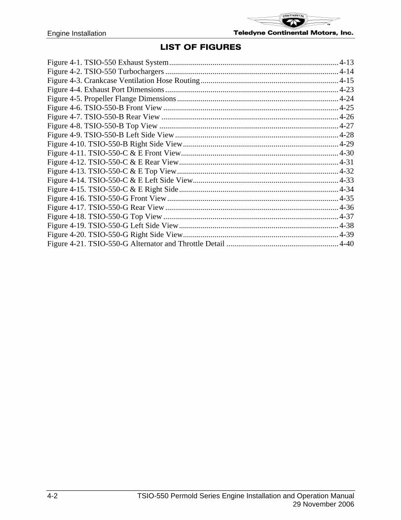
The items in the Special Tool List (Table 4-1) apply to engine installation.
Table 4-1. Special Tool List
Special Tools* Use or Reference Suggested Providers*
Part Number
Test Club Testing Hartzell Hartzell Porta-Test Model #20 ATM-C
Fuel Pump Calibration Approved Aircraft Accessories
20 ATM-C
Calibrated Gauges*** Fuel Pump Calibration --- --- Generator/Alternator Output Test
Check generator/alternator output. Borroughs** 8091
Alternator Analyzer Voltage Regulator Tester
Check alternator voltage regulation. Eastern Technology Corporation
647
Alternator/Regulator/ Battery Tester
Check battery and alternator voltage regulation.
Eastern Technology Corporation
E100
Voltage and Circuit Tester
Check circuit voltage. Eastern Technology Corporation
Model 29
EGT/CHT Tester Check Exhaust Gas Temperature/ Cylinder Head Temperature/ Turbine Inlet Temperature Accuracy
Alcor, Inc. ALCAL® 2000
Oil Filter Can Cutter Inspect particles in oil filter element. Federal Mogul CT-470 * Providers are subject to change and may discontinue manufacturing tools. ** Kell-Strom Tool Company has the manufacturing rights for Borroughs and Kent-Moore tools. *** Required if using to check fuel pressure as instructed in the section entitled “Fuel Pressure Operational Check with Calibrated Gauges” in Chapter 5 of this manual.
Engine Installation Teledyne Continental Motors, Inc.
TM
4-4 TSIO-550 Permold Series Engine Installation and Operation Manual 29 November 2006
4-1.1. Common Tools and Consumable Supplies Required
In addition to a full complement of mechanic’s tools, the following tools and materials are required for engine installation:
1. Hoist
2. Oil conforming to SAEJ 1966 (break-in oil, non-dispersant mineral oil) MIL-C-6529 Type II (Break-in oil – non-dispersant mineral oil).
3. Ashless dispersant oil conforming to SAEJ 1899
4. MIL-P-46002, Grade 1 oil
5. 100-LL Blue or 100 Green aviation fuel
6. Spark plugs and copper gaskets
7. Safety Wire (.032”)
8. Cable ties
9. Bladder-type pressure pot (at least 1 gallon capacity)
10. Type 1 flammable fuel container
11. Clean fuel hoses
12. AN union fittings
13. Rubber grommets
14. MS 122 DF Spray (available from Miller-Stephenson)
15. Anti-Seize compound
16. Loctite Hydraulic Sealant
17. Loctite Pipe Sealant
Teledyne Continental Motors, Inc.
TM
Engine Installation
TSIO-550 Permold Series Engine Installation and Operation Manual 4-5 29 November 2006
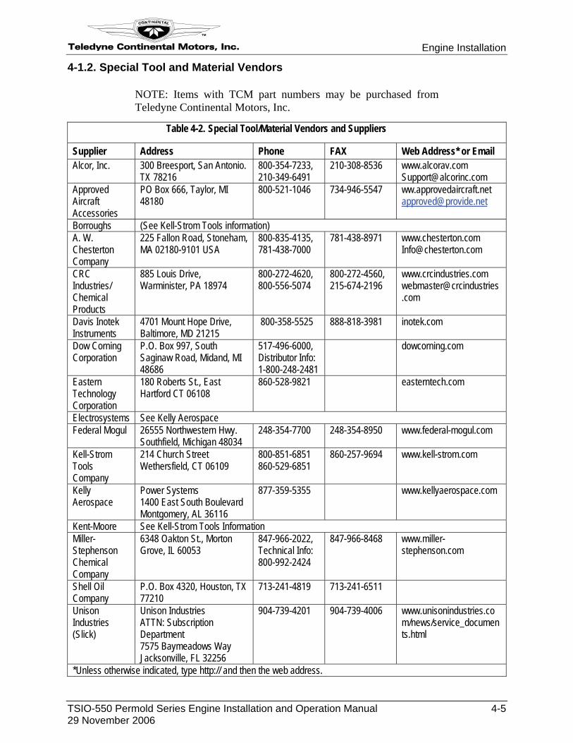
4-1.2. Special Tool and Material Vendors
NOTE: Items with TCM part numbers may be purchased from Teledyne Continental Motors, Inc.
Table 4-2. Special Tool/Material Vendors and Suppliers
Supplier Address Phone FAX Web Address* or Email Alcor, Inc. 300 Breesport, San Antonio.
TX 78216 800-354-7233, 210-349-6491
210-308-8536 www.alcorav.com [email protected]
Approved Aircraft Accessories
PO Box 666, Taylor, MI 48180
800-521-1046 734-946-5547 ww.approvedaircraft.net [email protected]
Borroughs (See Kell-Strom Tools information) A. W. Chesterton Company
225 Fallon Road, Stoneham, MA 02180-9101 USA
800-835-4135, 781-438-7000
781-438-8971 www.chesterton.com [email protected]
CRC Industries/ Chemical Products
885 Louis Drive, Warminister, PA 18974
800-272-4620, 800-556-5074
800-272-4560, 215-674-2196
www.crcindustries.com [email protected]
Davis Inotek Instruments
4701 Mount Hope Drive, Baltimore, MD 21215
800-358-5525 888-818-3981 inotek.com
Dow Corning Corporation
P.O. Box 997, South Saginaw Road, Midand, MI 48686
517-496-6000, Distributor Info: 1-800-248-2481
dowcorning.com
Eastern Technology Corporation
180 Roberts St., East Hartford CT 06108
860-528-9821 easterntech.com
Electrosystems See Kelly Aerospace Federal Mogul 26555 Northwestern Hwy.
Southfield, Michigan 48034 248-354-7700 248-354-8950 www.federal-mogul.com
Kell-Strom Tools Company
214 Church Street Wethersfield, CT 06109
800-851-6851 860-529-6851
860-257-9694 www.kell-strom.com
Kelly Aerospace
Power Systems 1400 East South Boulevard Montgomery, AL 36116
877-359-5355 www.kellyaerospace.com
Kent-Moore See Kell-Strom Tools Information Miller-Stephenson Chemical Company
6348 Oakton St., Morton Grove, IL 60053
847-966-2022, Technical Info: 800-992-2424
847-966-8468 www.miller-stephenson.com
Shell Oil Company
P.O. Box 4320, Houston, TX 77210
713-241-4819 713-241-6511
Unison Industries (Slick)
Unison Industries ATTN: Subscription Department 7575 Baymeadows Way Jacksonville, FL 32256
904-739-4201 904-739-4006 www.unisonindustries.com/news/service_documents.html
*Unless otherwise indicated, type http:// and then the web address.
Engine Installation Teledyne Continental Motors, Inc.
TM
4-6 TSIO-550 Permold Series Engine Installation and Operation Manual 29 November 2006
4-2. Engine Receipt and Handling
When the engine arrives, inspect the crating for damage. If the engine crating appears damaged, contact TCM’s Service Department (refer to the “TCM Contact Information” in Chapter 1 of this manual) and the freight shipping company. If the crating appears intact, proceed to the section “Uncrating the Engine”.
4-2.1. Uncrating the Engine
Procedure
1. Remove the four lag screws attaching the wooden cover to the base.
2. Lift the wooden cover and remove it.
3. Open the plastic bag wrapped around the engine.
4. Inspect the engine per instructions in the section “Acceptance Inspection” in this chapter.
NOTE: Environmental conditions (humidity), seasonal changes, and engine usage influence susceptibility to corrosion. In areas of high humidity, corrosion can occur within 2 days of uncrating the engine. The owner/operator is responsible for recognizing the risk of corrosion and taking the appropriate precautions.
5. If the engine is to be preserved, follow the instructions in Chapter 6 of this manual.
4-2.2. Crating an Engine for Shipping
If an engine needs to be returned to TCM or shipped to another location, crate the engine for shipping as follows:
Procedure
1. Lower the engine onto the container base.
2. Attach the engine using shock mounts and bolts.
3. Cover the engine with a plastic bag.
4. Install and attach the container cover to the base.
4-2.3. Acceptance Inspection
Procedure
1. Verify the engine serial number and model number on the engine nameplate are the same as specified in the engine logbook and the packing slip.
2. Inspect the engine for any signs of damage or corrosion.
a. If the engine exhibits no sign of damage or corrosion, proceed with installation. If the engine is to be installed within 30 days of unpacking, proceed to the section “Engine Preparation” in this chapter.
b. If the engine appears damaged or corroded, contact TCM’s Service Department (refer to the “TCM Contact Information” in Chapter 1). Do not install a damaged or corroded engine or place it in storage.
Teledyne Continental Motors, Inc.
TM
Engine Installation
TSIO-550 Permold Series Engine Installation and Operation Manual 4-7 29 November 2006
4-2.4. Engine Transport
Refer to the Installation Drawings at the end of this chapter for engine lifting eyes locations.
ProcedureAttach a hoist to the engine lifting eyes located at the top of the crankcase backbone.
1. Take up slack on the hoist prior to loosening the engine mount bolts; remove the bolts from the shipping shock mounts.
CAUTION: Do not allow chains to become entangled on the engine or its hardware. Be sure the area is clear when lifting the engine. Do not allow the front, rear, sides or bottom of the engine to strike any obstructions as the extreme weight may damage the engine or its components.
2. Lift the engine and install it on a transportation stand or dolly.
4-3. Installation Procedures
4-3.1. Prepare the Airframe for Engine Installation
Procedure
1. The following airframe components must be installed and in working order:
a. Aircraft fuel filter.
b. Aircraft fuel boost pump.
2. Clean the aircraft fuel strainer and allow at least 1 gallon of fuel to flow through the strainer and fuel supply line.
WARNING
Purge the aircraft fuel tanks and lines to remove all contamination prior to installation of the main fuel inlet line to the fuel pump. Failure to purge contamination may cause erratic Fuel Injection System operation.
Fuel injectors are sensitive to dirt and particulate contamination. To avoid contamination, do not disconnect fuel line connections between the fuel pump and the fuel injectors.
3. Replace all aircraft flexible oil and fuel hoses before engine installation.
4. Purge all aircraft fuel tanks and fuel lines to remove contaminants prior to installing any engine fuel line.
4-3.2. Prepare the Engine for Installation
This procedure applies to new, overhauled or stored engines. The objective is to remove packing material and tags, and the preservative fluid from the sump and fuel injection systems prior to installation.
Procedure
Engine Installation Teledyne Continental Motors, Inc.
TM
4-8 TSIO-550 Permold Series Engine Installation and Operation Manual 29 November 2006
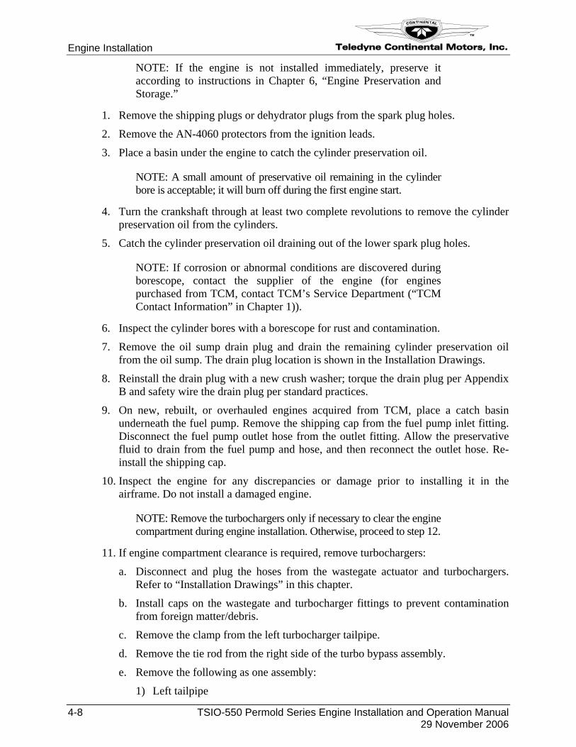
NOTE: If the engine is not installed immediately, preserve it according to instructions in Chapter 6, “Engine Preservation and Storage.”
1. Remove the shipping plugs or dehydrator plugs from the spark plug holes.
2. Remove the AN-4060 protectors from the ignition leads.
3. Place a basin under the engine to catch the cylinder preservation oil.
NOTE: A small amount of preservative oil remaining in the cylinder bore is acceptable; it will burn off during the first engine start.
4. Turn the crankshaft through at least two complete revolutions to remove the cylinder preservation oil from the cylinders.
5. Catch the cylinder preservation oil draining out of the lower spark plug holes.
NOTE: If corrosion or abnormal conditions are discovered during borescope, contact the supplier of the engine (for engines purchased from TCM, contact TCM’s Service Department (“TCM Contact Information” in Chapter 1)).
6. Inspect the cylinder bores with a borescope for rust and contamination.
7. Remove the oil sump drain plug and drain the remaining cylinder preservation oil from the oil sump. The drain plug location is shown in the Installation Drawings.
8. Reinstall the drain plug with a new crush washer; torque the drain plug per Appendix B and safety wire the drain plug per standard practices.
9. On new, rebuilt, or overhauled engines acquired from TCM, place a catch basin underneath the fuel pump. Remove the shipping cap from the fuel pump inlet fitting. Disconnect the fuel pump outlet hose from the outlet fitting. Allow the preservative fluid to drain from the fuel pump and hose, and then reconnect the outlet hose. Re-install the shipping cap.
10. Inspect the engine for any discrepancies or damage prior to installing it in the airframe. Do not install a damaged engine.
NOTE: Remove the turbochargers only if necessary to clear the engine compartment during engine installation. Otherwise, proceed to step 12.
11. If engine compartment clearance is required, remove turbochargers:
a. Disconnect and plug the hoses from the wastegate actuator and turbochargers. Refer to “Installation Drawings” in this chapter.
b. Install caps on the wastegate and turbocharger fittings to prevent contamination from foreign matter/debris.
c. Remove the clamp from the left turbocharger tailpipe.
d. Remove the tie rod from the right side of the turbo bypass assembly.
e. Remove the following as one assembly:
1) Left tailpipe
Teledyne Continental Motors, Inc.
TM
Engine Installation
TSIO-550 Permold Series Engine Installation and Operation Manual 4-9 29 November 2006
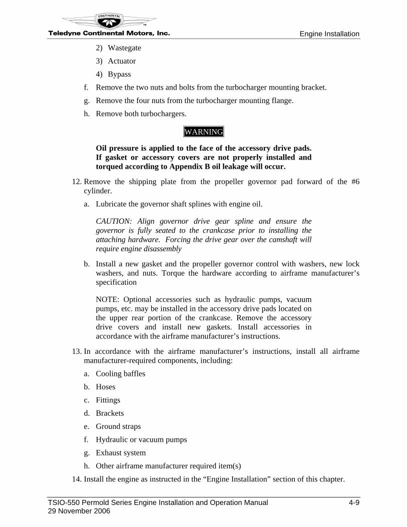
2) Wastegate
3) Actuator
4) Bypass
f. Remove the two nuts and bolts from the turbocharger mounting bracket.
g. Remove the four nuts from the turbocharger mounting flange.
h. Remove both turbochargers.
WARNING
Oil pressure is applied to the face of the accessory drive pads. If gasket or accessory covers are not properly installed and torqued according to Appendix B oil leakage will occur.
12. Remove the shipping plate from the propeller governor pad forward of the #6 cylinder.
a. Lubricate the governor shaft splines with engine oil.
CAUTION: Align governor drive gear spline and ensure the governor is fully seated to the crankcase prior to installing the attaching hardware. Forcing the drive gear over the camshaft will require engine disassembly
b. Install a new gasket and the propeller governor control with washers, new lock washers, and nuts. Torque the hardware according to airframe manufacturer’s specification
NOTE: Optional accessories such as hydraulic pumps, vacuum pumps, etc. may be installed in the accessory drive pads located on the upper rear portion of the crankcase. Remove the accessory drive covers and install new gaskets. Install accessories in accordance with the airframe manufacturer’s instructions.
13. In accordance with the airframe manufacturer’s instructions, install all airframe manufacturer-required components, including:
a. Cooling baffles
b. Hoses
c. Fittings
d. Brackets
e. Ground straps
f. Hydraulic or vacuum pumps
g. Exhaust system
h. Other airframe manufacturer required item(s)
14. Install the engine as instructed in the “Engine Installation” section of this chapter.
Engine Installation Teledyne Continental Motors, Inc.
TM
4-10 TSIO-550 Permold Series Engine Installation and Operation Manual 29 November 2006
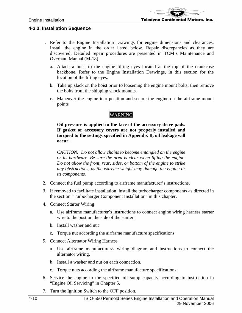
4-3.3. Installation Sequence
Procedure
1. Refer to the Engine Installation Drawings for engine dimensions and clearances. Install the engine in the order listed below. Repair discrepancies as they are discovered. Detailed repair procedures are presented in TCM’s Maintenance and Overhaul Manual (M-18).
a. Attach a hoist to the engine lifting eyes located at the top of the crankcase backbone. Refer to the Engine Installation Drawings, in this section for the location of the lifting eyes.
b. Take up slack on the hoist prior to loosening the engine mount bolts; then remove the bolts from the shipping shock mounts.
c. Maneuver the engine into position and secure the engine on the airframe mount points
WARNING
Oil pressure is applied to the face of the accessory drive pads. If gasket or accessory covers are not properly installed and torqued to the settings specified in Appendix B, oil leakage will occur.
CAUTION: Do not allow chains to become entangled on the engine or its hardware. Be sure the area is clear when lifting the engine. Do not allow the front, rear, sides, or bottom of the engine to strike any obstructions, as the extreme weight may damage the engine or its components.
2. Connect the fuel pump according to airframe manufacturer’s instructions.
3. If removed to facilitate installation, install the turbocharger components as directed in the section “Turbocharger Component Installation” in this chapter.
4. Connect Starter Wiring
a. Use airframe manufacturer’s instructions to connect engine wiring harness starter wire to the post on the side of the starter.
b. Install washer and nut
c. Torque nut according the airframe manufacture specifications.
5. Connect Alternator Wiring Harness
a. Use airframe manufacturer/s wiring diagram and instructions to connect the alternator wiring.
b. Install a washer and nut on each connection.
c. Torque nuts according the airframe manufacture specifications.
6. Service the engine to the specified oil sump capacity according to instruction in “Engine Oil Servicing” in Chapter 5.
7. Turn the Ignition Switch to the OFF position.
Teledyne Continental Motors, Inc.
TM
Engine Installation
TSIO-550 Permold Series Engine Installation and Operation Manual 4-11 29 November 2006
WARNING
Do not install the ignition harness “B” nuts on the spark plugs until the P-leads are connected and propeller installation is complete and the ignition system operational checkout is complete. Failure to comply can result in bodily injury when the propeller is rotated during installation.
8. Install the propeller according to the airframe and propeller manufacturer’s instructions.
CAUTION: Verify the ignition switch disables the magneto with a timing light before installing the spark plugs and ignition harness.
9. Connect the magneto P-leads from the ignition switch to the “switch” terminals on each magneto according to the airframe manufacturer’s instructions and check the switch for proper operation.
10. Perform the preoiling procedure as described in the “Engine Preoiling” section of this chapter. If Preoiling Method 2 is selected, install the spark plugs after preoiling.
11. If the magnetos were loosened or rotated during engine installation, adjust them according to the “Magneto to Engine Timing” instructions in Chapter 5.
12. Install remaining aircraft accessories, equipment, or instrumentation according to the aircraft manufacturer’s instructions.
13. Purge the fuel injection system after installation according to the instructions in section 4-3.3.4, “Fuel Injection System Purge.”
14. Perform the steps in section 4-3.4, “Installation Inspection.”
15. Inspect the engine for any debris, discrepancies, or damage. Correct any discrepancies.
WARNING
Do not operate the engine unless all of the following conditions are met and verified: All hardware, spark plugs, gaskets, seals are in place and torqued. (If they are not, oil leaks can occur) The oil sump is properly filled to the specified capacity with oil.
16. Perform an “Engine Operational Check” according to Chapter 5.
Engine Installation Teledyne Continental Motors, Inc.
TM
4-12 TSIO-550 Permold Series Engine Installation and Operation Manual 29 November 2006
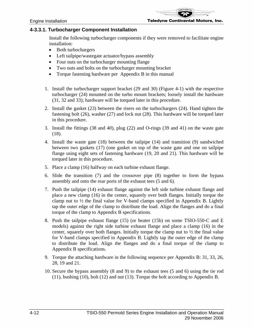
4-3.3.1. Turbocharger Component Installation Install the following turbocharger components if they were removed to facilitate engine installation: • Both turbochargers • Left tailpipe/wastegate actuator/bypass assembly • Four nuts on the turbocharger mounting flange • Two nuts and bolts on the turbocharger mounting bracket • Torque fastening hardware per Appendix B in this manual
Procedure
1. Install the turbocharger support bracket (29 and 30) (Figure 4-1) with the respective turbocharger (24) mounted on the turbo mount brackets; loosely install the hardware (31, 32 and 33); hardware will be torqued later in this procedure.
2. Install the gasket (23) between the risers on the turbochargers (24). Hand tighten the fastening bolt (26), washer (27) and lock nut (28). This hardware will be torqued later in this procedure.
3. Install the fittings (38 and 40), plug (22) and O-rings (39 and 41) on the waste gate (18).
4. Install the waste gate (18) between the tailpipe (14) and transition (9) sandwiched between two gaskets (17) (one gasket on top of the waste gate and one on tailpipe flange using eight sets of fastening hardware (19, 20 and 21). This hardware will be torqued later in this procedure.
5. Place a clamp (16) halfway on each turbine exhaust flange.
6. Slide the transition (7) and the crossover pipe (8) together to form the bypass assembly and onto the rear ports of the exhaust tees (5 and 6).
7. Push the tailpipe (14) exhaust flange against the left side turbine exhaust flange and place a new clamp (16) in the center, squarely over both flanges. Initially torque the clamp nut to ½ the final value for V-band clamps specified in Appendix B. Lightly tap the outer edge of the clamp to distribute the load. Align the flanges and do a final torque of the clamp to Appendix B specifications.
8. Push the tailpipe exhaust flange (15) (or heater (15b) on some TSIO-550-C and E models) against the right side turbine exhaust flange and place a clamp (16) in the center, squarely over both flanges. Initially torque the clamp nut to ½ the final value for V-band clamps specified in Appendix B. Lightly tap the outer edge of the clamp to distribute the load. Align the flanges and do a final torque of the clamp to Appendix B specifications.
9. Torque the attaching hardware in the following sequence per Appendix B: 31, 33, 26, 28, 19 and 21.
10. Secure the bypass assembly (8 and 9) to the exhaust tees (5 and 6) using the tie rod (11), bushing (10), bolt (12) and nut (13). Torque the bolt according to Appendix B.
Teledyne Continental Motors, Inc.
TM
Engine Installation
TSIO-550 Permold Series Engine Installation and Operation Manual 4-13 29 November 2006
CAUTION: the exhaust system requires freedom of movement for proper operation after installation. Ensure the bushing (10) is properly installed in the tie rod to allow expansion and the exhaust system parts have adequate clearance from surrounding objects after installation.
Bushing
Elongated hole
Bushing
Elongated hole
Figure 4-1. TSIO-550 Exhaust System 1 Elbow 13 Nut 23 Gasket 35 Hose 2 Elbow 14 Tailpipe 24 Turbocharger Assy. 36 Hose 3 Tee 15 Tailpipe 25 Gasket 37 Hose 4 Tee --- Reverse Tailpipe Option 26 Bolt 38 Fitting 5 Transition 15b Heater 27 Washer 39 O-ring 6 Transition 16 V-band Clamp 28 Lock Nut 40 Elbow Fitting 7 Riser 17 Gasket 29 Bracket 41 O-ring 8 Crossover 18 Waste Gate 30 Bracket 42 Adapter Fitting 9 Transition 19 Bolt 31 Screw 43 O-ring 10 Bushing 20 Washer 32 Washer 44 Elbow Fitting 11 Tie Rod 21 Lock Nut 33 Lock Nut 45 Reducer 12 Bolt 22 Plug 34 Controller 46 O-ring
Engine Installation Teledyne Continental Motors, Inc.
TM
4-14 TSIO-550 Permold Series Engine Installation and Operation Manual 29 November 2006
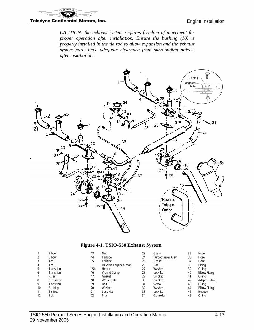
11. Assemble and attach the hose (15) (Figure 4-2) to the right oil reservoir (9) from the connecting tee (18).
12. Assemble and attach the hose (19) to the left oil reservoir (8) from connecting tee (18).
Figure 4-2. TSIO-550 Turbochargers 1 Left Turbocharger 8 Right Oil Reservoir 15 Hose 2 Right Turbocharger 9 Left Oil Reservoir 16 Hose 3 Gasket 10 Lock Washer 17 Hose 4 Adapter 11 Bolt 18 Tee 5 Lock Washer 12 Adapter 19 Hose 6 Bolt 13 Tee 20 Hose 7 Gasket 14 Check Valve 21 Hose
CAUTION: The tailpipe breather hose must be of suitable material to withstand exhaust temperatures.
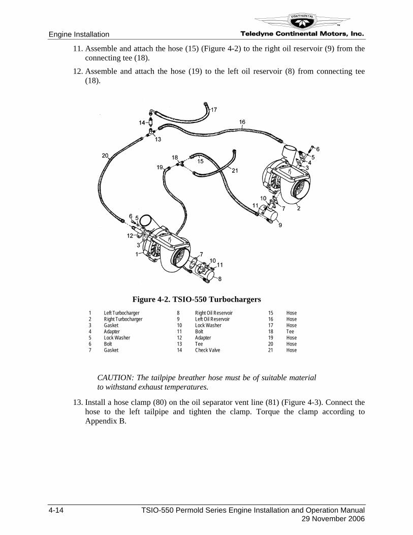
13. Install a hose clamp (80) on the oil separator vent line (81) (Figure 4-3). Connect the hose to the left tailpipe and tighten the clamp. Torque the clamp according to Appendix B.
Teledyne Continental Motors, Inc.
TM
Engine Installation
TSIO-550 Permold Series Engine Installation and Operation Manual 4-15 29 November 2006
Figure 4-3. Crankcase Ventilation Hose Routing
4-3.3.2. Propeller Installation Procedure
Consult the airframe manufacturer’s installation instruction for specific propeller installation steps.
Engine Installation Teledyne Continental Motors, Inc.
TM
4-16 TSIO-550 Permold Series Engine Installation and Operation Manual 29 November 2006
4-3.3.3. Engine Pre-oiling Engine preoiling must be accomplished prior to engine start-up after engine installation or overhaul/assembly. There are two pre-oiling methods:
NOTE: If engine cylinders were installed or the engine is new or overhauled, follow Pre-oiling Method 1.
4-3.3.3.1. Pre-oiling Method 1 Procedure
1. Install and torque the spark plugs and ignition lead wires as instructed in “Spark Plug Installation” and “Ignition Harness Installation” in Chapter 5.
2. Verify the lubrication lines, fittings, hoses, screens, and filters are in place prior to pre-oiling.
3. Obtain a 1-gallon capacity bladder-type pressure pot with an output pressure of 50 psi (not to exceed 60 psi).
4. Connect the pre-oiler supply hose to the engine oil pressure output (fitting).
5. Disconnect the safety wire from the engine oil filter and loosen (do not remove) the oil filter from the oil filter adapter.
6. Open the pre-oiler valve. Watch the seam of the oil filter for evidence of oil flow. Depending upon the oil temperature, it may take as long as 20 minutes to see an indication of oil flow.
7. Close the pre-oiler valve.
8. After oil flow confirmation, torque the oil filter according to Appendix B and safety wire the filter according to the instructions in Appendix C.
9. Disconnect the pre-oiler supply hose and cap; connect the engine oil pressure output to the oil pressure gauge connection (fitting).
WARNING
Do not operate this engine unless the oil is serviced to the proper level.
10. Check the oil level in the sump using the oil gauge rod (dip stick). Refer to “Engine Oil Servicing” in Chapter 5.
Teledyne Continental Motors, Inc.
TM
Engine Installation
TSIO-550 Permold Series Engine Installation and Operation Manual 4-17 29 November 2006
4-3.3.3.2. Pre-oiling Method 2 Procedure
1. If it has not already been done, service the oil level; refer to the sections “Engine Oil Servicing” in Chapter 5.
2. Turn the engine using the starter. The typical cycle is 30 seconds with the starter on, followed by 3 to 5 minutes to allow the starter to cool.
3. Spin the engine for a maximum total duration not to exceed 80 seconds or until the oil pressure gauge shows oil indication.
4. Install and torque the spark plugs and ignition lead wires as instructed in “Spark Plug Installation” and Ignition Harness Installation” in Chapter 5.
5. Check the oil level in the sump using the oil gauge rod (dip stick). Refer to “Engine Oil Servicing” in Chapter 5.
WARNING
Do not operate this engine unless the oil is serviced to the proper level.
Engine Installation Teledyne Continental Motors, Inc.
TM
4-18 TSIO-550 Permold Series Engine Installation and Operation Manual 29 November 2006
4-3.3.4. Fuel Injection System Purge Prior to shipping, the fuel injection system was preserved with MIL-PRF-6081D Grade 1010. The preservative fluid was drained during “Engine Preparation for Installation.” Flushing the system with aircraft fuel will complete the purge, ease engine starting and provide more accurate response during fuel system adjustments.
Procedure
1. Disconnect the fuel supply line at the inlet to the fuel manifold valve.
2. Connect a length of the appropriate size hose to the disconnected fuel manifold supply hose using an AN union fitting and secure the end of the hose in a properly grounded Type 1 flammable fluid container.
CAUTION: Ensure the magneto switch is in the OFF position and clear the rotational arc of the propeller before proceeding.
3. Have an assistant turn the aircraft master switch on.
4. Adjust the mixture control to full rich and the throttle to full open.
5. Place the aircraft boost pump in the on position for approximately one minute to purge the preservative fluid from the fuel system.
6. Turn the aircraft boost pump and master switch to the off position.
7. Close the mixture and throttle.
8. Remove the extra length of hose and union installed in step 2 from the fuel manifold valve supply hose.
9. Connect the fuel manifold valve fuel supply hose to the inlet fitting on the manifold valve and torque the fuel hose “B” nut to the value specified in Appendix B.
NOTE: Place approved containers at the induction system drain locations to collect fuel as it is drained overboard during the following procedure.
10. Have an assistant turn the aircraft master switch to the ON position.
11. With the mixture control in FULL RICH and the Throttle ¼ OPEN, turn the aircraft boost pump to the ON position.
12. Visually inspect all fuel injection system lines, hoses and fitting for evidence of fuel leakage.
13. Place the mixture control to IDLE CUT-OFF and CLOSE the THROTTLE.
14. Turn the aircraft fuel boost pump OFF.
15. Turn the aircraft Master Power Switch OFF.
16. Correct any discrepancies noted.
17. Dispose of the fuel/oil mixture in accordance with Federal and State Hazardous Material Regulations.
Teledyne Continental Motors, Inc.
TM
Engine Installation
TSIO-550 Permold Series Engine Installation and Operation Manual 4-19 29 November 2006
4-3.4. Installation Inspection
An Operational Inspection and a normal preflight ground run-up in accordance with the aircraft POH and Airplane Flight Manual (AFM) must be performed before the aircraft is approved by an airframe and powerplant mechanic for a Flight Check. The Flight Check is required to ensure the engine and aircraft meet all of the manufacturer’s performance and operational specifications prior to releasing the aircraft for normal service.
Procedure
Inspect the listed areas before attempting an engine start:
1. Engine Mounts
a. Engine mounts are free of cracks, corrosion or damage.
b. Engine and airframe mounting points are properly aligned and torqued as specified by the aircraft manufacturer.
c. Sufficient clearance exists between the engine (including any customer furnished items attached to the engine) and the aircraft/engine mount and cowling.
d. All engine to airframe connections are flexible and correctly supported to prevent vibration transmission, chafing and breakage.
2. Engine Fuel System
a. Fuel supply lines, valves, filters and fittings are sufficient size to provide adequate fuel flow for maximum power plus fuel return with running auxiliary fuel pump.
b. Fuel System has provisions for water and sediment isolation and drainage at its lowest points in normal ground attitude and that the drains are accessible.
c. Fuel lines and hoses are routed and supported to prevent exposure to excessive temperature.
d. Fuel lines and hoses are routed with no unnecessary bends, fittings or elevation changes.
e. Fuel lines and hoses are per TSO or fabricated from fire resistant material.
3. Exhaust System
a. Sufficient clearance or heat shielding between exhaust components and spark plugs, plug leads, mount isolators, induction system, engine controls, fuel system and heat sensitive airframe components.
b. Adequate support for tail pipes, heat exchangers and mufflers.
c. Flexibility provided for thermal expansion and engine movement.
d. Tail pipe exit is located away from fuel and oil drains to eliminate ignition.
4. Lubrication System
a. Oil cooler baffles are installed to maximize oil cooler efficiency.
b. Oil temperature and pressure monitoring sensors are installed correctly.
c. External oil lines to the engine are correctly routed and supported.
Engine Installation Teledyne Continental Motors, Inc.
TM
4-20 TSIO-550 Permold Series Engine Installation and Operation Manual 29 November 2006
d. Oil separator used on crankcase breather has oil return line free from low trap points or other areas where sludge deposits can stop drainage.
e. Crankcase breather is routed overboard, free of the airframe, will not create suction or pressure and is protected from freezing.
f. Oil screens and oil filters are accessible for service with minimal oil spillage.
g. Oil gauge rod is correctly installed and supported.
5. Air Induction System
a. Induction air filter is correctly installed.
b. Alternate air system door is connected, operates smoothly and seals properly in the closed position.
c. Flexible joints in the induction system are properly connected between airframe and engine.
d. Induction system drain check valves are properly installed and function correctly.
e. Induction system installation will not interfere with access to engine adjustments.
6. Electrical System
a. Engine is securely grounded to the airframe or directly grounded to the negative battery terminal with the adequate size ground wire.
b. Exposed positive connections are protected from accidental shorting with terminal boots or are enclosed in a protective box.
c. Magneto switches are independently grounded to the engine with shielded wire.
d. Magneto ground leads are routed through separate firewall connectors.
e. Electrical wire installations and instrumentation wiring harnesses are bundled neatly and have no unnecessary looping or kinking.
f. Engine electrical lead length sufficiently permits engine movement in all extremes without breaking wires.
g. Electrical wires are properly located and protected to prevent chafing, exposure to fuel, oil, heat radiation, moisture and all moving parts.
h. Wiring between battery, starter contact and starter are of sufficient size and as short as possible to prevent voltage drop.
7. Air Cooling Baffles And Cowling System
a. Fire proof and gas sealed firewall is intact and has sustained no damage during engine installation.
b. Replaced all baffles that are not sufficient to accommodate the relative air movement between the individual cylinders.
c. Baffles are not cracked and all fasteners are intact.
d. Baffles make proper seals between engine and closed cowling.
e. Baffle seals are installed and supported to provide adequate engine movement and maintain seal integrity within the cowl.
Teledyne Continental Motors, Inc.
TM
Engine Installation
TSIO-550 Permold Series Engine Installation and Operation Manual 4-21 29 November 2006
f. Baffles and fasteners will not affect the integrity of the engine.
g. Ducts, tubes, or other components do not interfere with the free flow of cooling air in or out of the cowling.
h. Temperature probes are properly located to accurately report cylinder head, turbine inlet, and exhaust gas temperatures.
8. Engine Controls
a. Controls are installed properly and accommodate engine movement without binding or change of adjustment.
b. Controls operate smoothly through full range of travel at control and controlled device.
c. Side loads on engine or accessory control shafts are not excessive. d. Control function and direction of movement is clearly marked e. Controls are installed to engine levers to minimize the possibility of engine
control separation. f. Friction lock for primary engine control is effective without using excessive force.
9. Engine Instrumentation
a. Engine instrumentation gauges are properly calibrated and function properly. b. Connections between engine and instruments are installed for accessibility and are
protected from chafing, heat and damage from engine motion. 10. Accessory Installation
a. Accessories are installed with proper gasket and properly torqued.
b. Accessories are the correct model to operate in the speed range provided by the engine drive or accessory drive.
Engine Installation Teledyne Continental Motors, Inc.
TM
4-22 TSIO-550 Permold Series Engine Installation and Operation Manual 29 November 2006
4-3.5. Preflight and Run-up
WARNING
Although the fuel system was adjusted on the test stand, the fuel system must be checked and adjusted in accordance with the “Engine Operational Check” section of Chapter 5 of this manual and current service documents when the engine is installed in the airframe to ensure proper operation. All discrepancies must be corrected prior to release for flight.
TSIO-550 Permold Series engines are not designed nor approved for continuous negative or zero gravity operation. Engine Mount loads shall not exceed FAR 23 utility category load factors.
CAUTION: Adhere to the Operating Limits specified in Chapter 2 during engine operation.
NOTE: New and factory rebuilt engines complete an acceptance test prior to shipment on a test stand. The engine will require an operational test and a flight check to complete engine break-in. After installation, avoid prolonged ground operation at high power.
Procedure
1. Perform the “Engine Operational Check” located in Chapter 5 of this manual.
2. Perform a “Flight Check” located in Chapter 7.
Teledyne Continental Motors, Inc.
TM
Engine Installation
TSIO-550 Permold Series Engine Installation and Operation Manual 4-23 29 November 2006
4-4. TSIO-550 Installation Drawings
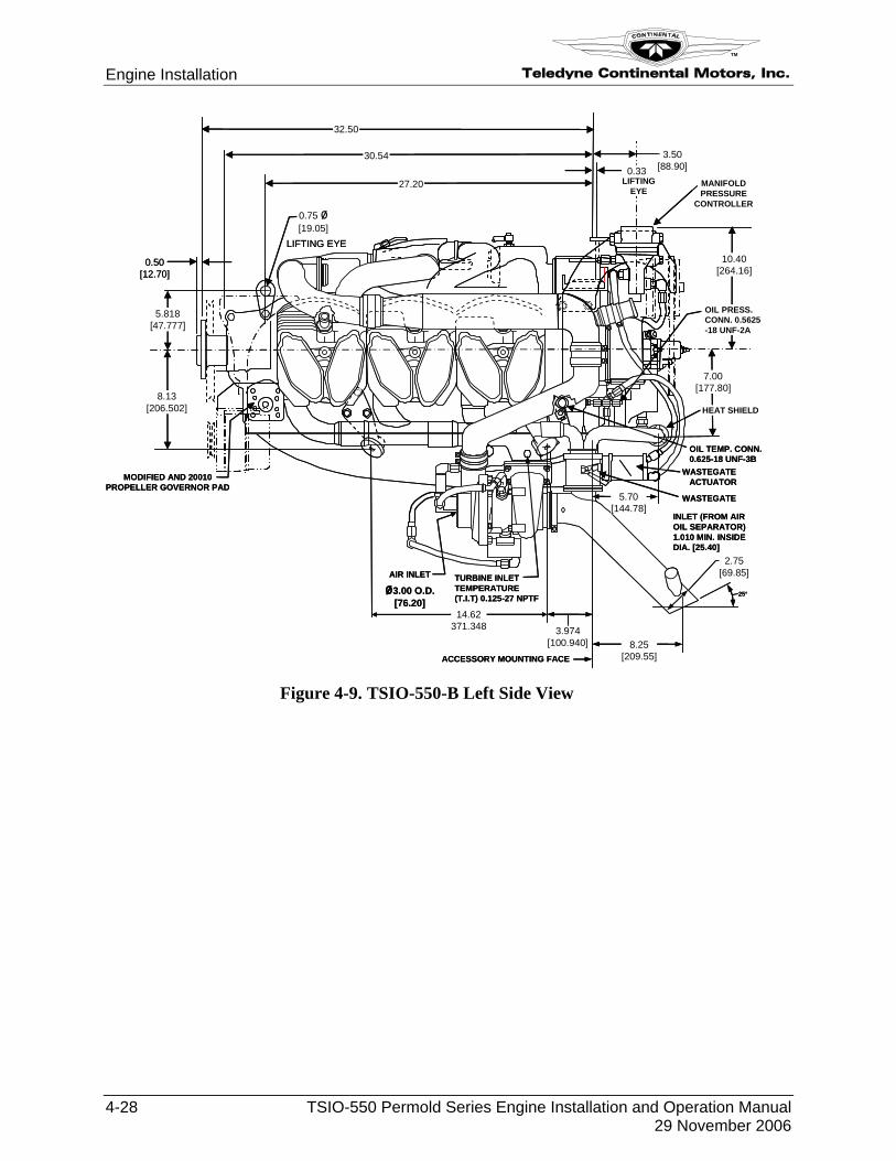
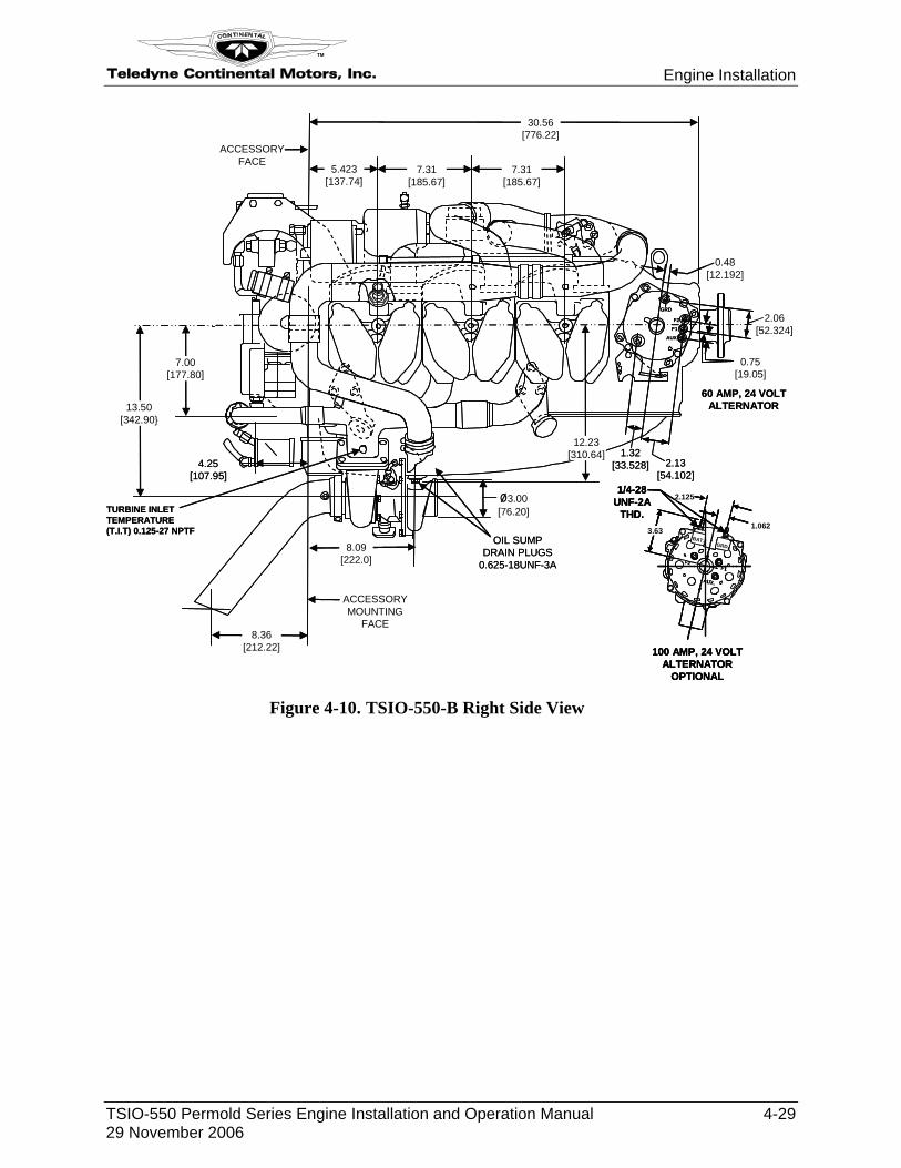
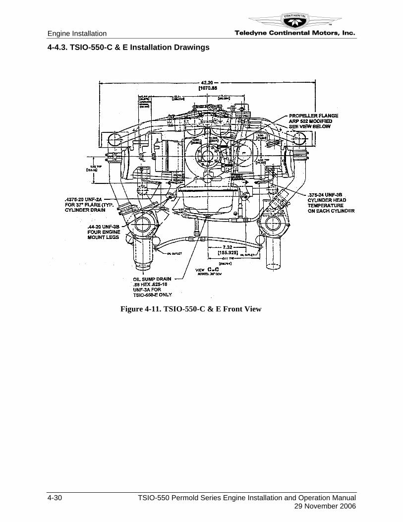
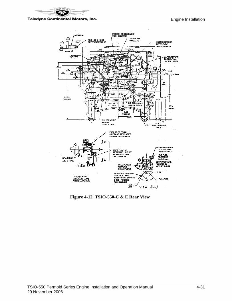
Installation drawings are provided to assist the airframe manufacturer determine appropriate fittings and fasteners for airframe interconnect and determine fit and limit requirements for engine compartment. Slight variations between the basic TSIO-550 B and subsequent engine models require separate engine installations. Pay particular attention to the model depicted when referencing drawings for engine installation requirements.
4-4.1. TSIO-550 Common Installation Drawings
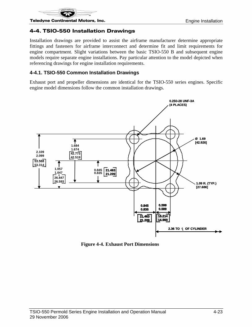
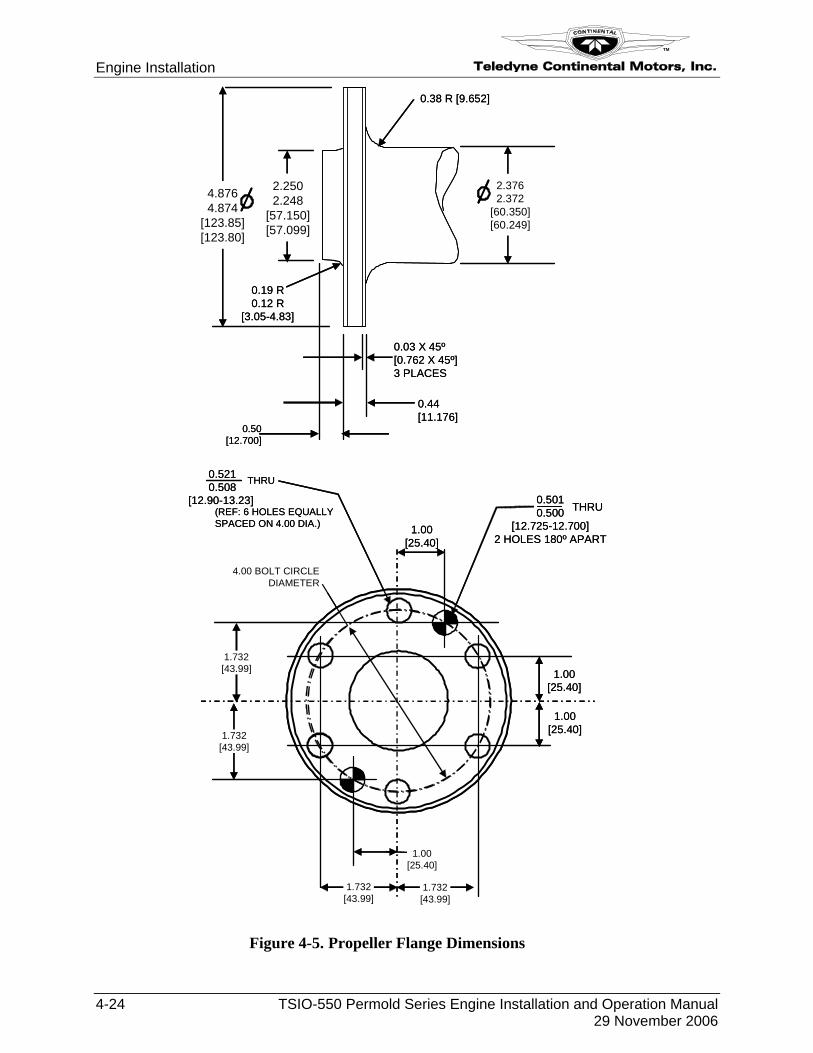
Exhaust port and propeller dimensions are identical for the TSIO-550 series engines. Specific engine model dimensions follow the common installation drawings.
0.250-28 UNF-3A(4 PLACES)
Ø 1.69[42.926]
2.1092.099
53.56853.314
2.36 TO OF CYLINDERCL
0.5990.589
0.8450.835
15.21414.960
21.46321.209
1.6841.67442.77342.519
1.0571.04726.84726.593 1.09 R. (TYP.)
[27.686]
0.8450.835
21.46321.209
0.250-28 UNF-3A(4 PLACES)
Ø 1.69[42.926]
2.1092.099
53.56853.314
2.1092.099
53.56853.31453.56853.314
2.36 TO OF CYLINDERCL
0.5990.589
0.8450.835
15.21414.960
21.46321.209
2.36 TO OF CYLINDERCLCL
0.5990.589
0.8450.835
15.21414.960
21.46321.209
0.5990.589
0.8450.835
15.21414.960
21.46321.209
0.5990.589
0.8450.835
15.21414.960
21.46321.209
15.21414.96015.21414.960
21.46321.20921.46321.209
1.6841.67442.77342.51942.77342.519
1.0571.04726.84726.593 1.09 R. (TYP.)
[27.686]
0.8450.835
21.46321.20921.46321.209
Figure 4-4. Exhaust Port Dimensions
Engine Installation Teledyne Continental Motors, Inc.
TM
4-24 TSIO-550 Permold Series Engine Installation and Operation Manual 29 November 2006
0.50[12.700]
0.19 R0.12 R
[3.05-4.83]
0.44[11.176]
0.38 R [9.652]
2.3762.372
[60.350][60.249]
0.03 X 45º[0.762 X 45º]3 PLACES
2.2502.248
[57.150][57.099]
4.8764.874
[123.85][123.80]
4.00 BOLT CIRCLEDIAMETER
1.732[43.99]
1.732[43.99]
1.00[25.40]
1.00[25.40]
1.00[25.40]
0.5210.508
[12.90-13.23]
THRU
(REF: 6 HOLES EQUALLYSPACED ON 4.00 DIA.)
0.5010.500
[12.725-12.700]2 HOLES 180º APART
THRU
1.00[25.40]
1.732[43.99]
1.732[43.99]
Figure 4-5. Propeller Flange Dimensions
Teledyne Continental Motors, Inc.
TM
Engine Installation
TSIO-550 Permold Series Engine Installation and Operation Manual 4-25 29 November 2006
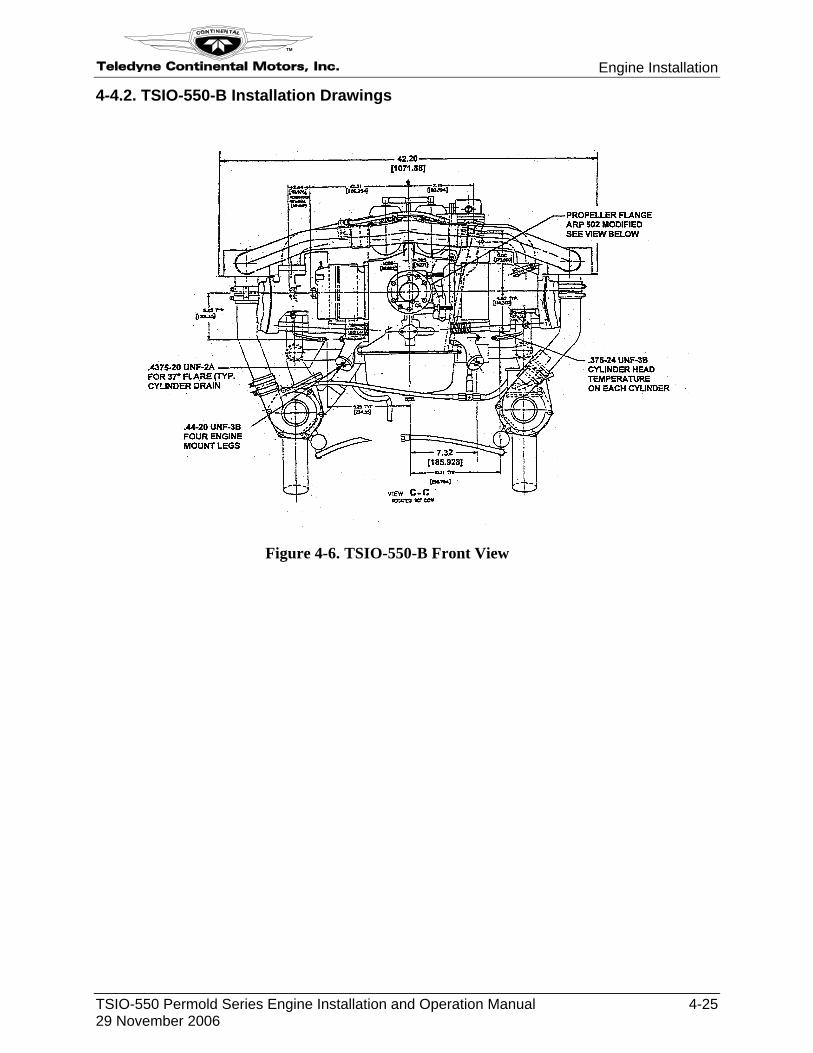
4-4.2. TSIO-550-B Installation Drawings
Figure 4-6. TSIO-550-B Front View
Engine Installation Teledyne Continental Motors, Inc.
TM
4-26 TSIO-550 Permold Series Engine Installation and Operation Manual 29 November 2006
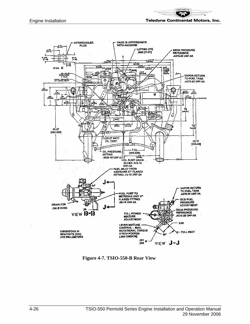
Figure 4-7. TSIO-550-B Rear View
Teledyne Continental Motors, Inc.
TM
Engine Installation
TSIO-550 Permold Series Engine Installation and Operation Manual 4-27 29 November 2006
Figure 4-8. TSIO-550-B Top View
Engine Installation Teledyne Continental Motors, Inc.
TM
4-28 TSIO-550 Permold Series Engine Installation and Operation Manual 29 November 2006
MODIFIED AND 20010PROPELLER GOVERNOR PAD
OIL TEMP. CONN.0.625-18 UNF-3B
27.20
5.818[47.777]
0.50[12.70]
8.13[206.502]
14.62371.348
AIR INLET
ø3.00 O.D.[76.20]
30.54
LIFTING EYE
32.50
8.25[209.55]
25°
2.75[69.85]
3.974[100.940]
5.70[144.78]
ACCESSORY MOUNTING FACE
TURBINE INLETTEMPERATURE(T.I.T) 0.125-27 NPTF
INLET (FROM AIROIL SEPARATOR)1.010 MIN. INSIDEDIA. [25.40]
WASTEGATEACTUATOR
WASTEGATE
7.00[177.80]
HEAT SHIELD
OIL PRESS.CONN. 0.5625-18 UNF-2A
10.40[264.16]
MANIFOLDPRESSURE
CONTROLLER
LIFTINGEYE
0.33
3.50[88.90]
0.75 ø[19.05]
Figure 4-9. TSIO-550-B Left Side View
Teledyne Continental Motors, Inc.
TM
Engine Installation
TSIO-550 Permold Series Engine Installation and Operation Manual 4-29 29 November 2006
GRD
F2
F1
AUX
5.423[137.74]
30.56[776.22]
7.31[185.67]
7.31[185.67]
ACCESSORYFACE
13.50[342.90}
8.36[212.22]
ACCESSORYMOUNTING
FACE
8.09[222.0]
OIL SUMPDRAIN PLUGS
0.625-18UNF-3A
12.23[310.64]
7.00[177.80]
4.25[107.95]
ø3.00[76.20]TURBINE INLET
TEMPERATURE(T.I.T) 0.125-27 NPTF
1/4-28UNF-2A
THD.
BAT.GRD.
F2F1
AUX.
3.63
2.125
1.062
100 AMP, 24 VOLTALTERNATOR
OPTIONAL
60 AMP, 24 VOLTALTERNATOR
1.32[33.528] 2.13
[54.102]
0.75[19.05]
2.06[52.324]
0.48[12.192]
GRD
F2
F1
AUX
5.423[137.74]
30.56[776.22]
7.31[185.67]
7.31[185.67]
ACCESSORYFACE
13.50[342.90}
8.36[212.22]
ACCESSORYMOUNTING
FACE
8.09[222.0]
OIL SUMPDRAIN PLUGS
0.625-18UNF-3A
12.23[310.64]
7.00[177.80]
4.25[107.95]
ø3.00[76.20]TURBINE INLET
TEMPERATURE(T.I.T) 0.125-27 NPTF
1/4-28UNF-2A
THD.
BAT.GRD.
F2F1
AUX.
3.63
2.125
1.062
100 AMP, 24 VOLTALTERNATOR
OPTIONAL
1/4-28UNF-2A
THD.
BAT.GRD.
F2F1
AUX.
3.63
2.125
1.062BAT.
GRD.F2
F1
AUX.
3.63
2.125
1.062
100 AMP, 24 VOLTALTERNATOR
OPTIONAL
60 AMP, 24 VOLTALTERNATOR
1.32[33.528] 2.13
[54.102]
0.75[19.05]
2.06[52.324]
0.48[12.192]
Figure 4-10. TSIO-550-B Right Side View
Engine Installation Teledyne Continental Motors, Inc.
TM
4-30 TSIO-550 Permold Series Engine Installation and Operation Manual 29 November 2006
4-4.3. TSIO-550-C & E Installation Drawings
Figure 4-11. TSIO-550-C & E Front View
Teledyne Continental Motors, Inc.
TM
Engine Installation
TSIO-550 Permold Series Engine Installation and Operation Manual 4-31 29 November 2006
22.36 [567.93]
22.36 [567.93]
Figure 4-12. TSIO-550-C & E Rear View
Engine Installation Teledyne Continental Motors, Inc.
TM
4-32 TSIO-550 Permold Series Engine Installation and Operation Manual 29 November 2006
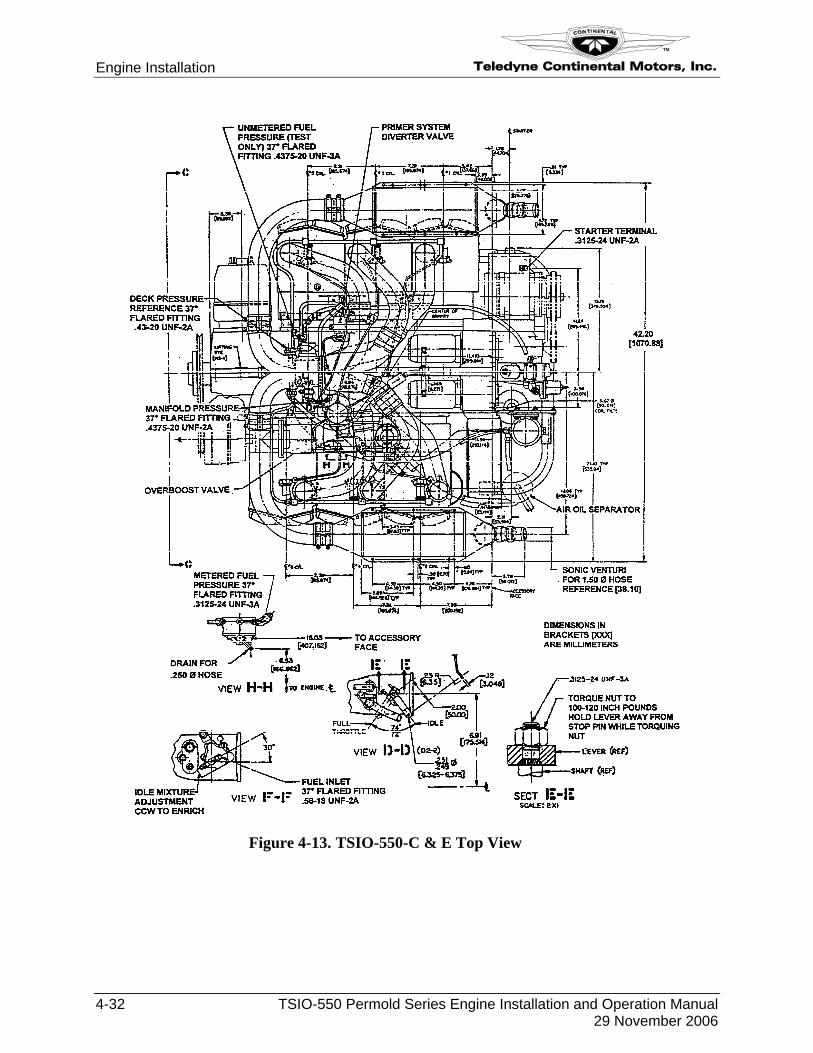
Figure 4-13. TSIO-550-C & E Top View
Teledyne Continental Motors, Inc.
TM
Engine Installation
TSIO-550 Permold Series Engine Installation and Operation Manual 4-33 29 November 2006
MODIFIED AND 20010PROPELLER GOVERNOR PAD
OIL TEMP. CONN.0.625-18 UNF-3B
27.20
5.818[47.777]
0.50[12.70]
8.13[206.502]
14.62371.348
AIR INLET
30.54
LIFTING EYE
32.50
8.25[209.55]
25°
2.75[69.85]
3.974[100.940]
5.70[144.78]
ACCESSORY MOUNTING FACE
TURBINE INLETTEMPERATURE(T.I.T) 0.125-27 NPTF
INLET (FROM AIROIL SEPARATOR)1.010 MIN. INSIDEDIA. [25.40]
WASTEGATEACTUATOR
WASTEGATE
7.00[177.80]
HEAT SHIELD
OIL PRESS.CONN. 0.5625-18 UNF-2A
10.40[264.16]
MANIFOLDPRESSURE
CONTROLLER
LIFTINGEYE
0.33
0.75 ø[19.05]
3.50[88.90]
40.26
DIMENSIONS INBRACKETS [XXX]
ARE MILLIMETERS
FOR TSI0-550-C ONLY
FOR TSI0-550-E ONLY
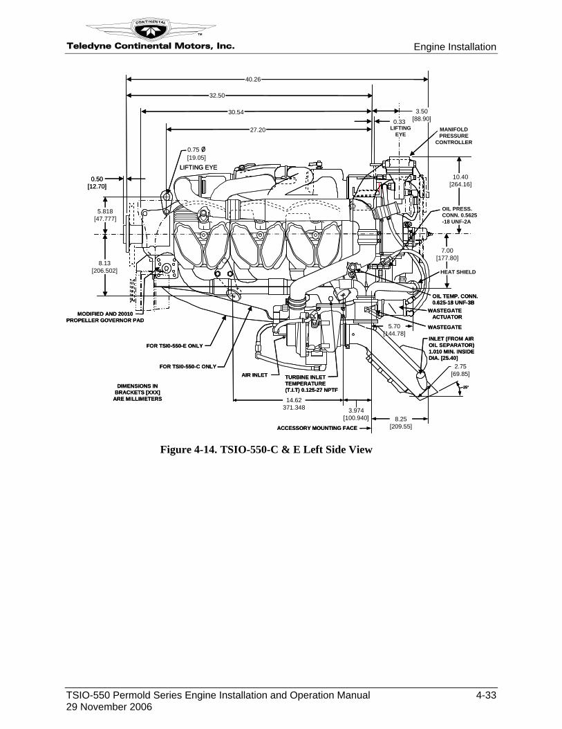
Figure 4-14. TSIO-550-C & E Left Side View
Engine Installation Teledyne Continental Motors, Inc.
TM
4-34 TSIO-550 Permold Series Engine Installation and Operation Manual 29 November 2006
GRD
F2
F1
AUX
5.423[137.74]
30.56[776.22]
7.31[185.67]
7.31[185.67]
ACCESSORYFACE
13.50[342.90} 10.97
[278.64]
8.36[212.22]
ACCESSORYMOUNTING
FACE
8.09[222.0]
OIL SUMPDRAIN PLUGS
0.625-18UNF-3A
12.23[310.64]
7.00[177.80]
4.25[107.95]
ø3.00[76.20]TURBINE INLET
TEMPERATURE(T.I.T) 0.125-27 NPTF
1/4-28UNF-2A
THD.
BAT.GRD.
F2F1
AUX.
3.63
2.125
1.062
100 AMP, 24 VOLTALTERNATOR
OPTIONAL
AUX+
F1F2
#6-32 UNC-2A THD.FIELD TERM. STUD
1/4-28 UNF-2A THD.OUTPUT TERM. STUD
#10-32 UNF-2A THD.AUX TERM. STUD
4.00
70 AMP, 12 VOLTALTERNATOR
OPTIONAL
60 AMP, 24 VOLTALTERNATOR
1.32[33.528] 2.13
[54.102]
0.75[19.05]
2.06[52.324]
0.48[12.192]
GRD
F2
F1
AUX
5.423[137.74]
30.56[776.22]
7.31[185.67]
7.31[185.67]
ACCESSORYFACE
13.50[342.90} 10.97
[278.64]
8.36[212.22]
ACCESSORYMOUNTING
FACE
8.09[222.0]
OIL SUMPDRAIN PLUGS
0.625-18UNF-3A
12.23[310.64]
7.00[177.80]
4.25[107.95]
ø3.00[76.20]TURBINE INLET
TEMPERATURE(T.I.T) 0.125-27 NPTF
1/4-28UNF-2A
THD.
BAT.GRD.
F2F1
AUX.
3.63
2.125
1.062
100 AMP, 24 VOLTALTERNATOR
OPTIONAL
1/4-28UNF-2A
THD.
BAT.GRD.
F2F1
AUX.
3.63
2.125
1.062BAT.
GRD.F2
F1
AUX.
3.63
2.125
1.062
100 AMP, 24 VOLTALTERNATOR
OPTIONAL
AUX+
F1F2
#6-32 UNC-2A THD.FIELD TERM. STUD
1/4-28 UNF-2A THD.OUTPUT TERM. STUD
#10-32 UNF-2A THD.AUX TERM. STUD
4.00
70 AMP, 12 VOLTALTERNATOR
OPTIONAL
60 AMP, 24 VOLTALTERNATOR
1.32[33.528] 2.13
[54.102]
0.75[19.05]
2.06[52.324]
0.48[12.192]
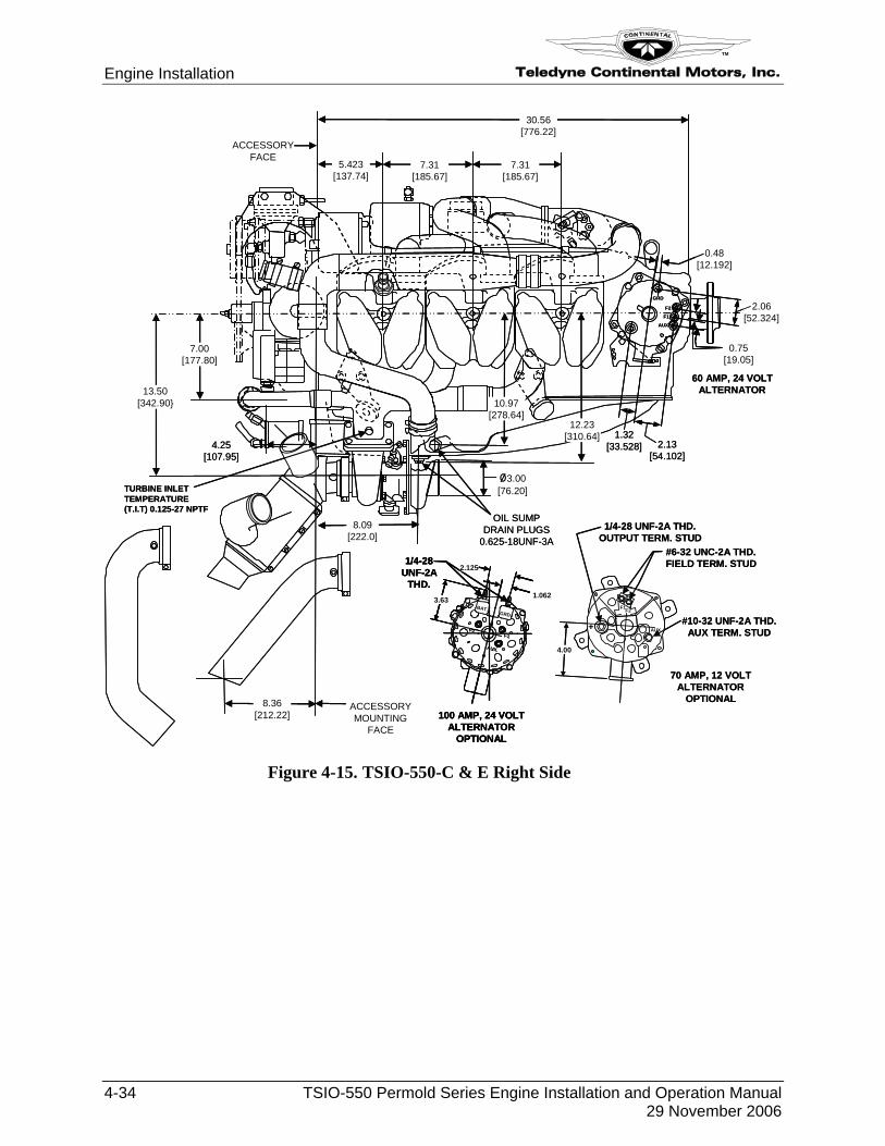
Figure 4-15. TSIO-550-C & E Right Side
Teledyne Continental Motors, Inc.
TM
Engine Installation
TSIO-550 Permold Series Engine Installation and Operation Manual 4-35 29 November 2006
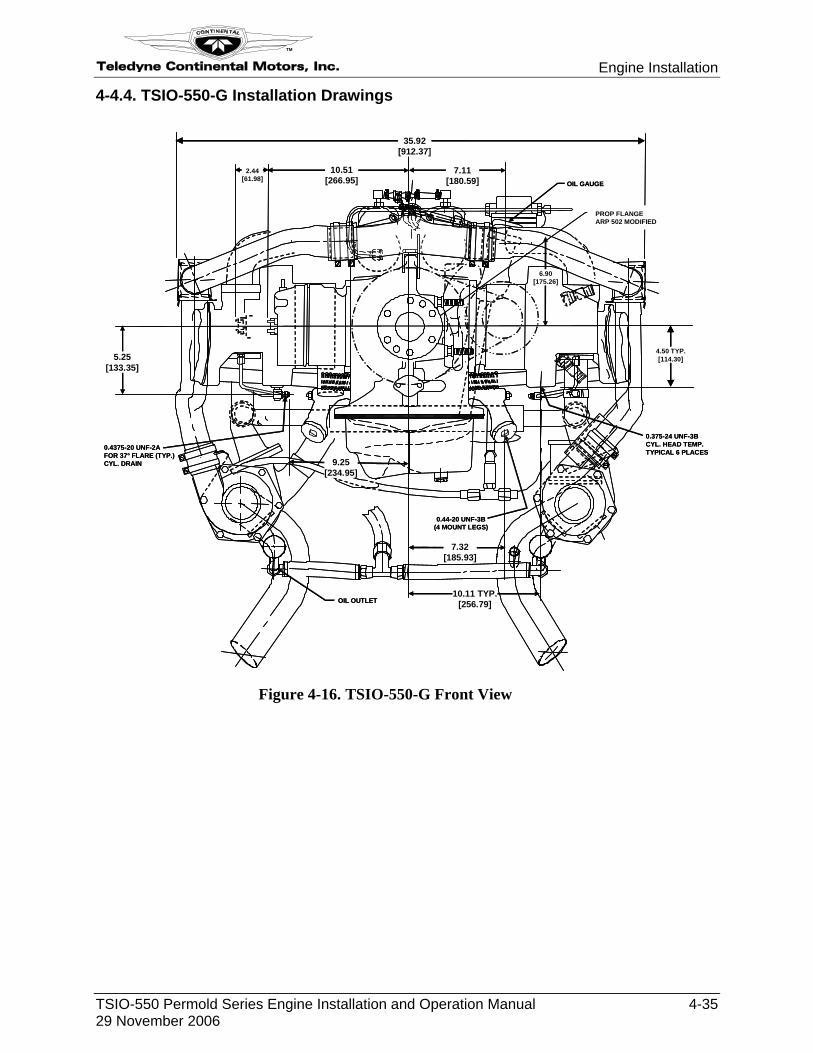
4-4.4. TSIO-550-G Installation Drawings
0.375-24 UNF-3BCYL. HEAD TEMP.TYPICAL 6 PLACES
7.32[185.93]
10.11 TYP.[256.79]OIL OUTLET
0.4375-20 UNF-2AFOR 37° FLARE (TYP.)CYL. DRAIN
5.25[133.35]
2.44[61.98]
10.51[266.95]
7.11[180.59]
PROP FLANGEARP 502 MODIFIED
OIL GAUGE
9.25[234.95]
0.44-20 UNF-3B(4 MOUNT LEGS)
6.90[175.26]
35.92[912.37]
4.50 TYP.[114.30]
Figure 4-16. TSIO-550-G Front View
Engine Installation Teledyne Continental Motors, Inc.
TM
4-36 TSIO-550 Permold Series Engine Installation and Operation Manual 29 November 2006
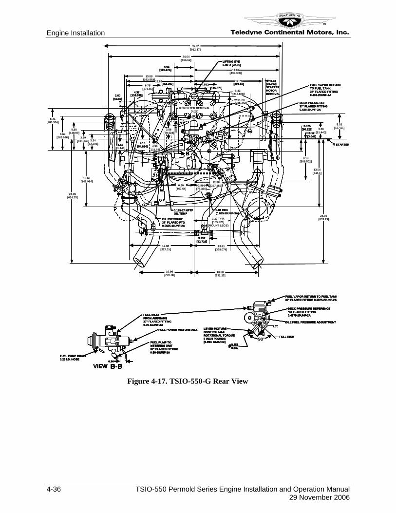
[115.875]
2.00[50.80]
4.37[110.998]
[364.202]
[285.242]
8.42
11.23
[213.868]
[324.61]0.63
[16.002]STARTERMOTORREMOVAL
6.69[169.926]
5.55[140.97]
3.24[82.296]
3.59[101.346]
8.21[208.534]
3.94[100.076] 17.02
12.78
[432.308]
4.562
13.88[352.552]13.63
6.75[171.45]
DECK PRESS. REF37° FLARED FITTING0.438-20UNF-2A
3.60[91.440]
2.375[60.325]
0.12[3.048]
CL STARTER
6.60[167.64]
12.88[327.152]2.966
[75.336]
OIL PRESSURE37° FLARED FTG0.5625-18UNF-2A
0.88 HEX(0.625-18UNF-3A)
3.257[82.728]
7.32 TYP.[185.928]
(MOUNT LEGS)
13.31[338.074]
0.125-27 NPTFOIL TEMP
2.16[54.864]1.62
[41.148]
24.99[634.75]
13.66[346.964]
LIFTING EYE0.89 ∅ [22.61]
13.08[332.23]
10.96[278.38]
8.13[206.502]
13.55[344.1]
24.95[633.73]
FUEL VAPOR RETURNTO FUEL TANK37° FLARED FITTING0.438-20UNF-2A
FULL POWER MIXTURE ADJ.
FUEL PUMP TOMETERING UNIT37° FLARED FITTING0.56-18UNF-2A
0.96
FUEL PUMP DRAIN0.25 I.D. HOSE
VIEW B-B
FUEL INLETFROM AIRFRAME37° FLARED FITTING0.75-16UNF-2A
LEVER-MIXTURECONTROL MAX.ROTATIONAL TORQUE5 INCH POUNDS[0.893 GMS/CM]
0.2510.249ø
1.70
FULL RICH
IDLE FUEL PRESSURE ADJUSTMENT
DECK PRESSURE REFERENCE°37 FLARED FITTING0.4375-20UNF-2A
FUEL VAPOR RETURN TO FUEL TANK37° FLARED FITTING 0.4375-20UNF-2A
90°
B
B
34.04[864.62]
35.92[912.37]
12.88[327.15]
5.02[127.51]3.56
[90.424]
4.56[115.83]
0.56 FILTER REMOVAL[4.22]
[115.875]
2.00[50.80]
4.37[110.998]
[364.202]
[285.242]
8.42
11.23
[213.868]
[324.61]0.63
[16.002]STARTERMOTORREMOVAL
6.69[169.926]
5.55[140.97]
3.24[82.296]
3.59[101.346]
8.21[208.534]
3.94[100.076] 17.02
12.78
[432.308]
4.562
13.88[352.552]13.63
6.75[171.45]
DECK PRESS. REF37° FLARED FITTING0.438-20UNF-2A
3.60[91.440]
2.375[60.325]
0.12[3.048]
CLCL STARTER
6.60[167.64]
12.88[327.152]2.966
[75.336]
OIL PRESSURE37° FLARED FTG0.5625-18UNF-2A
0.88 HEX(0.625-18UNF-3A)
3.257[82.728]
7.32 TYP.[185.928]
(MOUNT LEGS)
13.31[338.074]
0.125-27 NPTFOIL TEMP
2.16[54.864]1.62
[41.148]
24.99[634.75]
13.66[346.964]
LIFTING EYE0.89 ∅ [22.61]
13.08[332.23]
10.96[278.38]
8.13[206.502]
13.55[344.1]
24.95[633.73]
FUEL VAPOR RETURNTO FUEL TANK37° FLARED FITTING0.438-20UNF-2A
FULL POWER MIXTURE ADJ.
FUEL PUMP TOMETERING UNIT37° FLARED FITTING0.56-18UNF-2A
0.96
FUEL PUMP DRAIN0.25 I.D. HOSE
VIEW B-B
FUEL INLETFROM AIRFRAME37° FLARED FITTING0.75-16UNF-2A
LEVER-MIXTURECONTROL MAX.ROTATIONAL TORQUE5 INCH POUNDS[0.893 GMS/CM]
0.2510.249ø
1.70
FULL RICH
IDLE FUEL PRESSURE ADJUSTMENT
DECK PRESSURE REFERENCE°37 FLARED FITTING0.4375-20UNF-2A
FUEL VAPOR RETURN TO FUEL TANK37° FLARED FITTING 0.4375-20UNF-2A
90°
B
B
34.04[864.62]
35.92[912.37]
12.88[327.15]
5.02[127.51]3.56
[90.424]
4.56[115.83]
0.56 FILTER REMOVAL[4.22]
Figure 4-17. TSIO-550-G Rear View
Teledyne Continental Motors, Inc.
TM
Engine Installation
TSIO-550 Permold Series Engine Installation and Operation Manual 4-37 29 November 2006
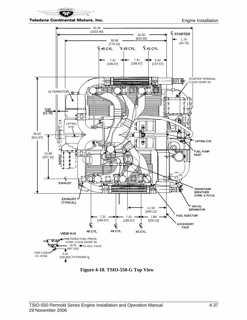
11.54[293.12]
7.88[200.15]
7.31[185.67]
CL CL CL#6 CYL. #4 CYL. #2 CYL.
32.50[825.50] 1.76
[44.70]
CL STARTER
L #5 CYL.
5.42[137.67]
CL #3 CYL. CL #1 CYL.C
0.50[12.70]
35.92[912.37]
CL
EXHAUST(TYPICAL)
LIFTING EYE
CRANKCASEBREATHERCONN. 0.75 O.D.
FUEL PUMPINLET
FUEL INJECTOR
EXHAUST
12.88[327.15]
7.31[185.67]
AIR OILSEPARATOR
ACCESSORYFACE
ALTERNATOR
STARTER TERMINAL0.3125-24UNF-2A
40.26[1022.60]
LIFTINGEYE
FOR 0.250I.D. HOSE
METERED FUEL PRESSCONN. 0.3125-24UNF-3A
TO ACC. FACE16.03[407.162]
6.53[166.862] TO ENGINE C
H H
VIEW H-H
30.56[776.22]
7.31[185.67]
7.31[185.67]
11.54[293.12]
7.88[200.15]
7.31[185.67]
CL CL CL#6 CYL. #4 CYL. #2 CYL.
32.50[825.50] 1.76
[44.70]
CL STARTER
L #5 CYL.
5.42[137.67]
CL #3 CYL. CL #1 CYL.C
0.50[12.70]
35.92[912.37]
CL
EXHAUST(TYPICAL)
LIFTING EYE
CRANKCASEBREATHERCONN. 0.75 O.D.
FUEL PUMPINLET
FUEL INJECTOR
EXHAUST
12.88[327.15]
7.31[185.67]
AIR OILSEPARATOR
ACCESSORYFACE
ALTERNATOR
STARTER TERMINAL0.3125-24UNF-2A
40.26[1022.60]
LIFTINGEYE
FOR 0.250I.D. HOSE
METERED FUEL PRESSCONN. 0.3125-24UNF-3A
TO ACC. FACE16.03[407.162]
6.53[166.862] TO ENGINE C
FOR 0.250I.D. HOSE
METERED FUEL PRESSCONN. 0.3125-24UNF-3A
TO ACC. FACE16.03[407.162]
6.53[166.862] TO ENGINE C
H H
VIEW H-H
30.56[776.22]
7.31[185.67]
7.31[185.67]
Figure 4-18. TSIO-550-G Top View
Engine Installation Teledyne Continental Motors, Inc.
TM
4-38 TSIO-550 Permold Series Engine Installation and Operation Manual 29 November 2006
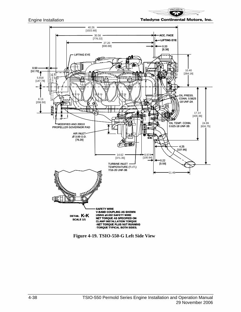
MODIFIED AND 20010PROPELLER GOVERNOR PAD
OIL TEMP. CONN.0.625-18 UNF-3B
27.20[690.88]
5.818[147.78]
0.50[12.70]
8.13[206.50]
0.33[8.38]
14.62[371.35]
AIR INLETO 3.00 O.D.
[76.20]
OIL PRESS.CONN. 0.5625-18 UNF-2A
30.56[776.22]
40.26[1022.60]
LIFTING EYE
3.974
TURBINE INLETTEMPERATURE (T.I.T.)7/16-20 UNF-3B
11.46
10.40[264.16]
SAFETY WIREV-BAND COUPLING AS SHOWNUSING ø0.032 SAFETY WIRENET TORQUE AS SPECIFIED ONCLAMP INSTALLATION TORQUE-NET TORQUE PLUS NUT RUNNING-TORQUE TYPICAL BOTH SIDES.
DETAIL K-KSCALE 1/1
K
K
ACC. FACE
LIFTING EYE
17.14[435.36]
24.99[634.75]
4.25[107.95]
0.22[5.59]
[100.94]
MODIFIED AND 20010PROPELLER GOVERNOR PAD
OIL TEMP. CONN.0.625-18 UNF-3B
27.20[690.88]
5.818[147.78]
0.50[12.70]
8.13[206.50]
0.33[8.38]
14.62[371.35]
AIR INLETO 3.00 O.D.
[76.20]
OIL PRESS.CONN. 0.5625-18 UNF-2A
30.56[776.22]
40.26[1022.60]
LIFTING EYE
3.974
TURBINE INLETTEMPERATURE (T.I.T.)7/16-20 UNF-3B
11.46
10.40[264.16]
SAFETY WIREV-BAND COUPLING AS SHOWNUSING ø0.032 SAFETY WIRENET TORQUE AS SPECIFIED ONCLAMP INSTALLATION TORQUE-NET TORQUE PLUS NUT RUNNING-TORQUE TYPICAL BOTH SIDES.
DETAIL K-KSCALE 1/1
SAFETY WIREV-BAND COUPLING AS SHOWNUSING ø0.032 SAFETY WIRENET TORQUE AS SPECIFIED ONCLAMP INSTALLATION TORQUE-NET TORQUE PLUS NUT RUNNING-TORQUE TYPICAL BOTH SIDES.
DETAIL K-KSCALE 1/1
K
K
ACC. FACE
LIFTING EYE
17.14[435.36]
24.99[634.75]
4.25[107.95]
0.22[5.59]
[100.94]
Figure 4-19. TSIO-550-G Left Side View
Teledyne Continental Motors, Inc.
TM
Engine Installation
TSIO-550 Permold Series Engine Installation and Operation Manual 4-39 29 November 2006
GRD
F2
F1
AUX
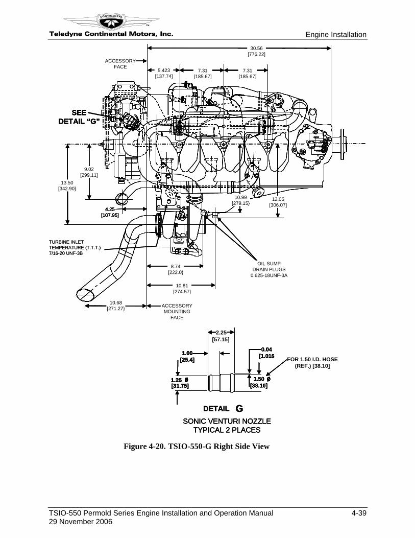
5.423[137.74]
30.56[776.22]
7.31[185.67]
7.31[185.67]
ACCESSORYFACE
13.50[342.90}
10.99[279.15}
10.68[271.27} ACCESSORY
MOUNTINGFACE
8.74[222.0}
10.81[274.57}
OIL SUMPDRAIN PLUGS
0.625-18UNF-3A
12.05[306.07]
ø
0.04[1.016
1.25[31.75]
ø 1.50[38.10]
1.00[25.4]
[57.15]2.25
FOR 1.50 I.D. HOSE(REF.) [38.10]
DETAIL G
SEEDETAIL “G”
SONIC VENTURI NOZZLETYPICAL 2 PLACES
9.02[299.11]
4.25[107.95]
GRD
F2
F1
AUX
5.423[137.74]
30.56[776.22]
7.31[185.67]
7.31[185.67]
ACCESSORYFACE
13.50[342.90}
10.99[279.15}
10.68[271.27} ACCESSORY
MOUNTINGFACE
8.74[222.0}
10.81[274.57}
OIL SUMPDRAIN PLUGS
0.625-18UNF-3A
12.05[306.07]
ø
0.04[1.016
1.25[31.75]
ø 1.50[38.10]
1.00[25.4]
[57.15]2.25
FOR 1.50 I.D. HOSE(REF.) [38.10]
DETAIL G
SEEDETAIL “G”
SONIC VENTURI NOZZLETYPICAL 2 PLACES
9.02[299.11]
4.25[107.95]
TURBINE INLET TEMPERATURE (T.T.T.) 7/16-20 UNF-3B
GRD
F2
F1
AUX
5.423[137.74]
30.56[776.22]
7.31[185.67]
7.31[185.67]
ACCESSORYFACE
13.50[342.90}
10.99[279.15}
10.68[271.27} ACCESSORY
MOUNTINGFACE
8.74[222.0}
10.81[274.57}
OIL SUMPDRAIN PLUGS
0.625-18UNF-3A
12.05[306.07]
ø
0.04[1.016
1.25[31.75]
ø 1.50[38.10]
1.00[25.4]
[57.15]2.25
FOR 1.50 I.D. HOSE(REF.) [38.10]
DETAIL G
SEEDETAIL “G”
SONIC VENTURI NOZZLETYPICAL 2 PLACES
9.02[299.11]
4.25[107.95]
TURBINE INLET TEMPERATURE (T.T.T.) 7/16-20 UNF-3B
Figure 4-20. TSIO-550-G Right Side View
Engine Installation Teledyne Continental Motors, Inc.
TM
4-40 TSIO-550 Permold Series Engine Installation and Operation Manual 29 November 2006
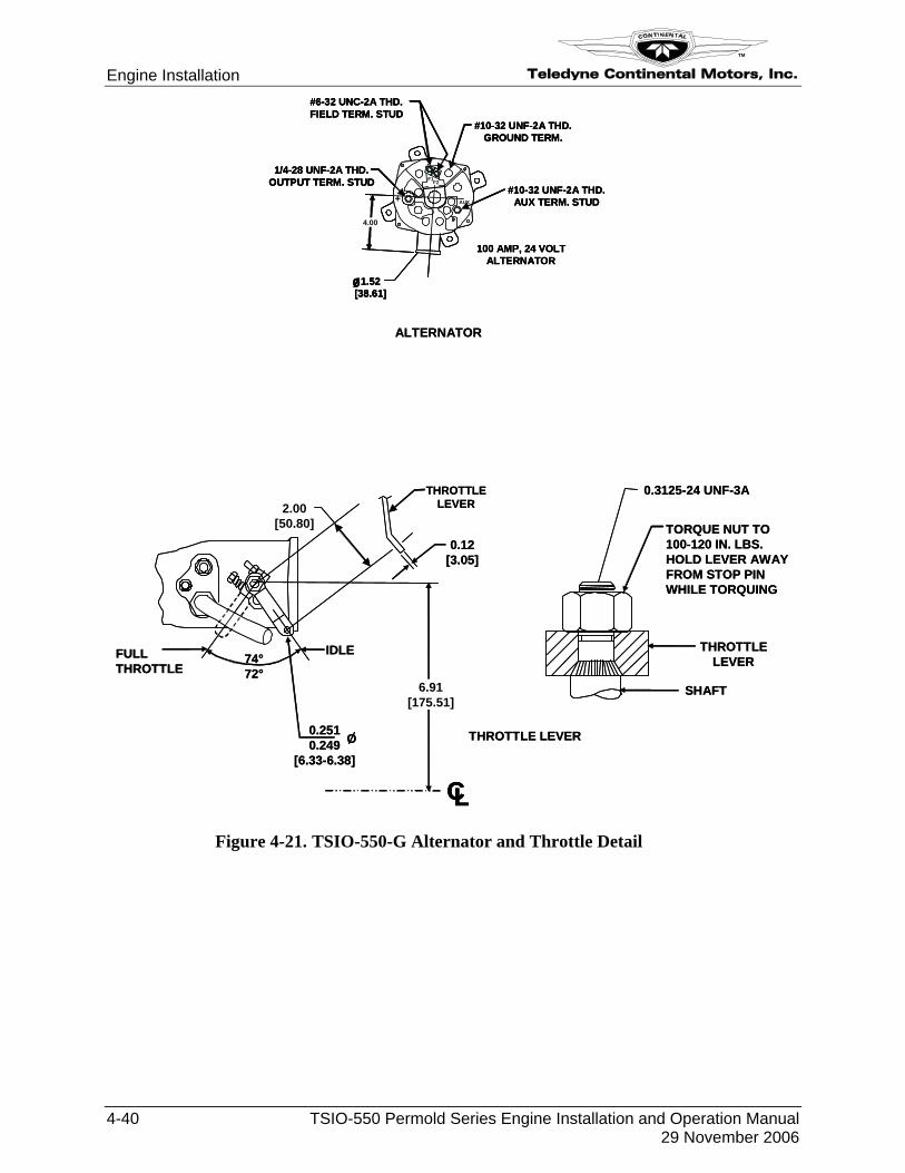
ALTERNATOR
TORQUE NUT TO100-120 IN. LBS.HOLD LEVER AWAYFROM STOP PINWHILE TORQUING
0.3125-24 UNF-3A
THROTTLELEVER
CL
FULLTHROTTLE
74°72°
0.2510.249
[6.33-6.38]
O
0.12[3.05]
IDLE
6.91[175.51]
THROTTLE LEVER
AUX+
F1F2
#6-32 UNC-2A THD.FIELD TERM. STUD
1/4-28 UNF-2A THD.OUTPUT TERM. STUD
#10-32 UNF-2A THD.AUX TERM. STUD
4.00
100 AMP, 24 VOLTALTERNATOR
#10-32 UNF-2A THD.GROUND TERM.
1.52[38.61]ø
2.00[50.80]
THROTTLELEVER
SHAFT
ALTERNATOR
TORQUE NUT TO100-120 IN. LBS.HOLD LEVER AWAYFROM STOP PINWHILE TORQUING
0.3125-24 UNF-3A
THROTTLELEVER
CLCL
FULLTHROTTLE
74°72°
0.2510.249
[6.33-6.38]
O
0.12[3.05]
IDLE
6.91[175.51]
THROTTLE LEVER
AUX+
F1F2
#6-32 UNC-2A THD.FIELD TERM. STUD
1/4-28 UNF-2A THD.OUTPUT TERM. STUD
#10-32 UNF-2A THD.AUX TERM. STUD
4.00
100 AMP, 24 VOLTALTERNATOR
#10-32 UNF-2A THD.GROUND TERM.
1.52[38.61]ø
AUX+
F1F2
#6-32 UNC-2A THD.FIELD TERM. STUD
1/4-28 UNF-2A THD.OUTPUT TERM. STUD
#10-32 UNF-2A THD.AUX TERM. STUD
4.00
100 AMP, 24 VOLTALTERNATOR
#10-32 UNF-2A THD.GROUND TERM.
1.52[38.61]ø
2.00[50.80]
THROTTLELEVER
SHAFT
Figure 4-21. TSIO-550-G Alternator and Throttle Detail


![Tranco: A Research-Oriented Top Sites Ranking Hardened Against … · 2019-02-14 · dated list4 consisting of one million websites since December 2008 [5]. Usually only pay-level](https://img.pdfslide.us/doc/110x75/5f5d883ac33a68028c33eae9/tranco-a-research-oriented-top-sites-ranking-hardened-against-2019-02-14-dated.jpg)