Embed Size (px)
Citation preview

1
TABLE 1. NMP GENERAL INSTRUCTIONS
BURNER AIR SETTING SPEED TAPMODEL BECKETT BURNER B.T.U.H.
OUTPUTB.T.U.H. INPUT
(USGPH) AFUE % NOZZLE PUMPp.s.i.
INSERTIONinches Shutter Air Band
CHIMNEY FLUEPRESSURE
(in w.c.)
GROSSSTACK °F
FILTER SIZE(QTY) GT12-7 G9
EXTERNAL STATICPRESSURE (in w.c.)
NMP-117 AFG60YHHSSS 117,000 139,400 (1.00) 80.7 Delavan 1.00 X 70o A 100 5" 10 1 -0,02 510 16" X 24" (2) MED-HI HI 0.20MED-HI 0.50
NMP-101 AFG60YHHSSS 101,000 118,490 (0.85) 81.7 Delavan 0.85 X 70o A 100 5" 8 0 -0,02 470 16" X 24" (2) MED MED-HI 0.20MED 0.50
NMP-89 AFG60YHHSSS 89,000 104,550 (0.75) 82.7 Delavan 0.75 X 70o A 100 5" 6 0 -0,02 450 16" X 24" (2) LO MED-LO 0.20MED-LO 0.50
NMP-77 AFG60YHHSSS 77,000 90,610 (0.65) 82.5 Delavan 0.65 X 70o A 100 5" 5 0 -0,02 430 16" X 24" (2) LO LO 0.20LO 0.50
SPEED TAPMODEL BECKETT BURNER B.T.U.H.
OUTPUTB.T.U.H. INPUT
(USGPH)AFUE
% NOZZLE PUMPp.s.i.
INSERTIONinches
BURNER AIR SETTING FIELDCONTROLS AIRBOOT
GROSSSTACK °F
FILTER SIZE(QTY) GT12-7 G9
EXTERNAL STATICPRESSURE (in w.c.)
NMP-117V AFG60YHHSSS 117,000 139,400 (1.00) 81.4 Delavan 1.00 X 70o A 100 5" 510 16" X 24" (2) MED-HI HI 0.2035MED-HI 0.50
NMP-101V AFG60YHHSSS 101,000 118,490 (0.85) 82.4 Delavan 0.85 X 70o A 100 5" 470 16" X 24" (2) MED MED-HI 0.2027
MED 0.50NMP-89V AFG60YHHSSS 89,000 104,550 (0.75) 83.4 Delavan 0.75 X 70o A 100 5" 450 16" X 24" (2) LO MED-LO 0.20
25MED-LO 0.50
NMP-77V AFG60YHHSSS 77,000 90,610 (0.65) 83.2 Delavan 0.65 X 70o A 100 5" 430 16" X 24" (2) LO LO 0.2020
LO 0.50
BURNER AIR SETTING SPEED TAPMODEL RIELLO BURNER B.T.U.H.
OUTPUTB.T.U.H. INPUT
(USGPH)AFUE
% NOZZLE PUMPp.s.i.
INSERTIONinches TURBULATOR SHUTTER
CHIMNEY FLUEPRESSURE
(in w.c.)
GROSSSTACK °F
FILTER SIZE(QTY) GT12-7 G9
EXTERNAL STATICPRESSURE (in w.c.)
NMP-109 40 F3 109,000 128,248 (0.92) 81.2 Delavan 0.75 X 60o B 150 4-5/8" 3 3.1 -0,02 460 16" X 24" (2) MED HI 0.20MED-HI 0.50
NMP-95 40 F3 95,000 111,520 (0.80) 82.2 Delavan 0.65 X 60o B 150 4-5/8" 2 2.7 -0,02 425 16" X 24" (2) MED-LO MED-HI 0.20MED 0.50
NMP-90 40 F3 89,000 103,156 (0.74) 82.7 Delavan 0.60 X 60o B 150 4-5/8" 1.5 2.5 -0,02 400 16" X 24" (2) MED-LO MED-LO 0.20MED 0.50
BURNER AIR SETTING SPEED TAPMODEL RIELLO BURNER B.T.U.H.
OUTPUTB.T.U.H. INPUT
(USGPH)AFUE
% NOZZLE PUMPp.s.i.
INSERTIONinches TURBULATOR SHUTTER
GROSSSTACK °F
FILTER SIZE(QTY) GT12-7 G9
EXTERNAL STATICPRESSURE (in w.c.)
NMP-109V 40 BF3 109,000 128,248 (0.92) 81.6 Delavan 0.75 X 60o B 150 4-5/8" 3 3.3 460 16" X 24" (2) MED HI 0.20MED-HI 0.50
NMP-95V 40 BF3 95,000 111,520 (0.80) 82.6 Delavan 0.65 X 60o B 150 4-5/8" 2 3.1 425 16" X 24" (2) MED-LO MED-HI 0.20MED 0.50
NMP-90V 40 BF3 89,000 103,156 (0.74) 83.1 Delavan 0.60 X 60o B 150 4-5/8" 1.5 2.9 400 16" X 24" (2) MED-LO MED-LO 0.20MED 0.50
Models ending with V can be used with the Newmac SVS sealed vent system.Use burner air settings as a guide only. Set burner air to give a trace of smoke. Re-adjust burner air to reduce CO2 to 1 to 1.5 percent. Take measurements with the burner cover & air ducts installed (if any).The maximum allowable temperature rise is 85 °F. Select speed to suit specific installation requirements. Air temperature can be lowered by increasing the blower speed, lowering the firing rate, or increasing supply & returnoutlets.The minimum recommended temperature rise is 65 °F. The minimum return air temperature is 60 °F.

2
TABLE 2. NMP BLOWER PERFORMANCE
DIRECT DRIVEBLOWER
BLOWERMOTOR SPEED TAP RPM
STATICPRESSURE(IN. W.C.)
CFM A/CTONS
HIGH 1,045 1,610 4.00MED-HI 850 1,200 3.00MEDIUM 750 1,090 2.50MED-LO 710 860 2.00
DELHI GT12-7 DD ¾ HP5 SPD
LO 680
0.50
760 1.75HIGH 1,040 1,735
MED-HI 760 1,260MEDIUM 650 1,115MED-LO 585 915
DELHI GT12-7 DD ¾ HP5 SPD
LO 540
0.20
800HIGH 1110 1,340
MED-HI 1050 1,310MED-LO 980 1,275
DELHI G9 DD 1/2 HP4 SPD
LO 920
0.20
1,170
TABLE 3. NMP CLEARANCES
The minimum clearances to combustible materials are as follows:
Model Description Side OtherSide
BlowerSide
SupplySide
Backor
Rear
SupplyPlenum
Top
SupplyPlenumAll Sides
HorizontalDucts within3 ft. of unit
ReturnDuctTop
ReturnDuct AllSides
CasingTop
Bottomto Floor Front Flue Floor
Upflow 2 2 2 2 2 1 0 24” 9 Combustible
Horizontal Right 0 2 2 2 2 1 1 1 2 2 24” 9NMP
Horizontal Left 0 2 2 2 2 1 1 1 2 2 24” 9
All dimensions in inches.
* Measured from panel on which burner is installed. Allow sufficient room for servicing.

3
FURNACE LOCATION
IMPORTANTPlease read this entire manual and all labels before installing the furnace.
UNPACKING AND INSPECTIONIt is the responsibility of the consignee of the unit to examine the packages for damage and, if found, tonote the same on the Carrier’s Bill of Lading.
The NMP furnace is shipped complete with oil burner, draft regulator, filter racks, air filters, A/C ControlCenter (optional) and instruction manual. For models shipped with SVS system, the draft regulator is notrequired.
Caution: Remove shipping retaining bracket from blower before start-up if required.
HEAT LOSSBefore installation, verify the furnace output capacity meets the building heat loss requirements. A detailedheat loss analysis is recommended.
INSTALLATION REGULATIONSThis unit should be installed in accordance with the regulations of the authority having jurisdiction. InCanada the installation must conform to CSA Standard B139, "The Installation Code for Oil BurningEquipment." In the United States, the National Fire Protection Association Standard NFPA 31 should befollowed. Check with provincial, state, or local codes concerning clearances, venting systemrequirements and other regulations governing installation. Some codes may vary from the requirementsset forth in this manual.
HORIZONTAL INSTALLATIONMounting kits are available from Newmac. Follow the instructions supplied with the kit. Observe requiredclearances.
FOUNDATIONTo ensure the furnace is on a level foundation and above any possible dampness, a cement pad isrecommended.
FOR YOUR SAFETY: Do not store or use gasoline or flammable vapors and liquids in the vicinityof this or any other appliance.
VENTING PRODUCTS OF COMBUSTION
CHIMNEYSThe required maximum flue pressure at the appliance breech is –0.02 inches of water column. A negativeoverfire pressure should be maintained. Locate the furnace as close to the chimney or flue as possible.The maximum draft is obtained by keeping elbows and pipe length to a minimum. Install the flue pipe witha gradual rise of at least 1/4" per foot from the furnace to the flue. Do not extend the flue pipe beyond theinside wall of the chimney. Refer to Table 11(a) and Table 11(b) for proper chimney flue sizing and Fig.20 for optimizing chimney draft.
The owner shall provide a chimney constructed to comply with the following specifications:(a) The chimney must be absolutely smoke tight throughout its entire length, and must extend at leastthree feet (3') above a flat roof or two feet above the ridges of peak roofs.(b) If built of a single thickness of brick or of cement blocks, it shall be lined throughout its entire lengthwith fire clay lining, having not less than three-fourths inch (3/4") thickness. Flue lining is to be laid inmortar and made airtight. If the chimney is of the prefabricated type, it must be an approved class "A"chimney or type "L" Vent for interior.(c) The furnace flue must have no other openings for attaching any fireplace, stove, range, gas orventilating connection unless the equipment is appropriately certified.

4
(d) If it is necessary to offset the flue, it must be done in such a manner as not to reduce the gross cross-sectional area or create a ledge or obstruction, where loose material may lodge.(e) Flue pipe connections must be secured with metal screws.
CAUTION: Oil-fired appliances shall be connected to flues or vents having sufficient draft at alltimes to ensure safe and proper operation of the appliance.
BAROMETRIC DRAFT REGULATORA Listed/Certified draft regulator must be installed between the appliance and the chimney, within easyreach for adjustment and free from obstruction. Use larger or multiple draft regulators for chimneys withstrong draft. Follow the manufacturer's instructions located with the draft regulator for proper installation.
NEWMAC SEALED VENT SYSTEMConsult TABLE 1, GENERAL INSTRUCTIONS of this manual for approved burners. Follow theinstructions supplied with the SVS system for proper installation. Refer to Fig.12, 13, or 14 in this manualfor wiring.
PROPER DUCT SIZING
Locate the furnace as close as possible to the center of the heat distribution system and make sure thetop is level. Refer to TABLES 7 and 8, DUCT SIZING FOR HEATING and COOLING in this manual.
AIR CONDITIONINGThis appliance is designed to accommodate air conditioning equipment. Models equipped with the fantimer control are A/C ready. An A/C fan center control can be installed on models equipped with a fan &limit control. Live motor leads must be isolated on direct drive motors using a two speed fan & limit controlor a suitable fan center control.
HUMIDIFIERIf a humidifier is installed, ensure water cannot drip on the heat exchanger. This will damage the furnaceand void the warranty.
ELECTRICAL CONNECTIONS
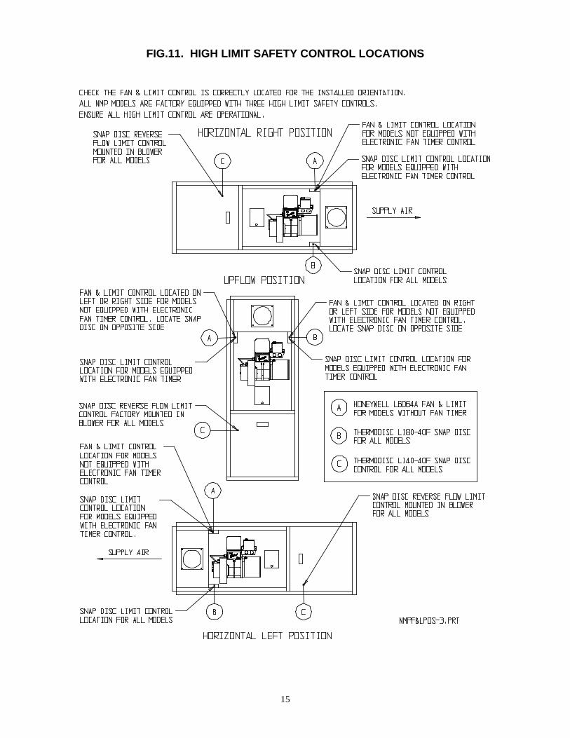
See the furnace marking label. Follow the Canadian or U.S. National Electrical Code as well as provincial,state, and local regulations. Figs. 12, 13 and 14 show standard wiring schematics.
FUEL SYSTEMS
Fuel not heavier than No. 2 fuel oil must be used. The oil supply tank must be of a listed or certified type acceptableto the regulatory authority having jurisdiction. Install the oil tank or tanks according to local codes and regulations.The tank should be kept at least 1/4 full. If a two-pipe system is used, suction and return lines should be of the samediameter and extend to the same depth in the tank. An emergency oil shut-off valve should be installed as requiredby local ordinance. This can be manual, electric solenoid, or vacuum operated. An oil safety valve that cuts the fuelsupply unless a vacuum is created by the pump is recommended. Any leaks in the system will prevent oil fromflowing. Suntec PRV or Webster OSV valves are recommended. Loop copper lines connected directly to the oilpump to reduce vibration. Use separate oil line for each individual appliance to prevent “loss of prime” problems.Refer to Fig. 9.
THERMOSTATLocate the thermostat on an interior wall free from drafts approximately 5 feet above floor level. The operation of theburner is normally controlled by the room thermostat, which may be set for the temperature desired, typically 70°F. ifa higher or lower temperature is desired, the indicator should be set to the proper point on the scale.
THERMOSTAT HEAT ANTICIPATORTo prevent short cycling, the heat anticipator should be set as recommended in the specifications for the burnerprimary control. This is typically set at 0.1 or 0.2 amps as indicated in Figure 1. This adjustment changes thethermostat’s response time to prevent the room temperature from over-running the thermostat setting.

5
FIG. 1 - Heat Anticipator
WARNING: The heat anticipator will BURN OUT if 25 volts are applied directly to the thermostat byshorting out the primary control during testing or incorrect wiring. If this happens the thermostatwarranty is void.
FAN & LIMIT CONTROL – MODEL NMP FL
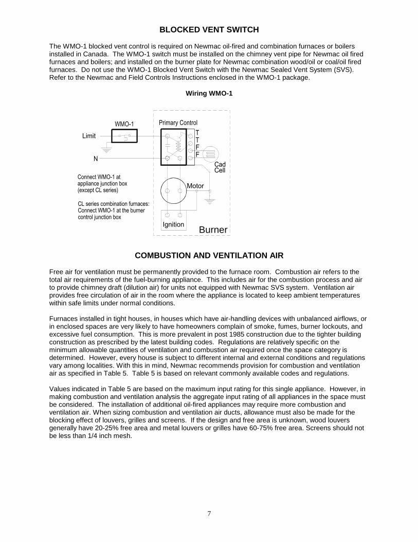
This thermally operated control has a probe to sense air temperature inside the appliance adjacent to theheat exchanger. Refer to Fig. 3 for its settings and Fig.11 for correct positioning of control.
High Limit Setting: See Figs. 2 and 3. This setting is factory set – DO NOT CHANGEThe high limit setting limits burner operation. When the air temperature inside the appliance reaches theset high limit value, overheating of the furnace is prevented by cutting power to the burner. When thetemperature falls below the set high limit the burner power is restored.
Fan-On Setting: See Figs. 2 and 3. This setting starts the air circulation blower when the burner haswarmed the furnace to the fan-on temperature
Fan-Off Setting: See Figs. 2 and 3. This setting keeps the air circulation blower running until thetemperature of the heat exchanger drops to the fan-off temperature. This ensures the blower adequatelycools the heat exchanger before shutting off and keeps cool air from being circulated through theductwork.
Fan differential (difference between the Fan On & Fan Off settings) should be at least 15oF (8 oC).
FIG. 2. TWO SPEED FAN & LIMIT CONTROL - L6064

6
FIG. 3. FAN AND LIMIT SETTINGS
FAN ON FAN OFF LIMIT*UPFLOW 125 90 200
HORIZONTALL
135 90 200* Do not change high limit setting
FAN TIMER CONTROL – MODEL NMP FT
This electronically operated fan timer integrates control of all burner and blower operations. The purposeof the ST9103A is to monitor the thermostat for Heat, Cool or other blower demands and run the burnerprimary control. The ST9103A also monitors the limit switches, which will cause the primary control toshut the burner off when the limit circuit is broken. There is a fixed 30-second blower-on time and a fieldadjustable 60, 90, 120, 150-second blower-off time (factory set at 120 seconds). All ST9103A controls areA/C ready and can operate three blower speeds. Pre and post purge times effect the operation of theblower. The pre and post purge times can be added to the blower on/off times on the ST9103A todetermine the blower operation times. For an operating sequence see Table 4.
TABLE 4. FAN TIMER CONTROL OPERATING SEQUENCE
ACTION SYSTEM RESPONSE
Thermostat calls for heat.(W terminal is energized.)
ST9103A closes oil primary control T-T connections. Ignition system and oil primary control start the furnace. Oil flows as long as oil primary control
senses flame. Burner motor is energized and heat fan on delay timing begins. When timing is complete, the
circulating fan is energized at heat speed and warm air is delivered to the controlled space.
Thermostat ends call for heat.(W terminal is de-energized.)
Oil primary control is de-energized, terminating the burner cycle. Heat fan off delay timing begins. When timing is complete, the circulating fan is de-energized. ST9103A returns to standby mode (oil primary control and circulating fan are off.)
Burner fails to light. Oil primary control locks out within lockout timing (timing depends on oil primary control.) Burner motor is de-energized. If heat fan has started, it continues through the selected delay off period.
Established flame fails. Burner motor is de-energized and oil primary control goes into recycle mode. If selected heat fan off delay is longer than the recycle delay timing, the heat fan continues to run
through the next trial for ignition.Thermostat begins call for cool.(G and Y terminals are energized.)
Circulating fan is energized at cool speed. Cooling compressor turns on immediately.
Thermostat ends call for cool.(G and Y terminals are de-energized)
Circulating fan and cooling compressor turns off immediately.
Thermostat begins call for fan.(G terminal is energized.)
Circulating fan is energized at cool speed. Cooling compressor turns on immediately.
Thermostat ends call for fan.(G terminal is de-energized.)
Circulating fan is de-energized.
Limit switch string opens. Oil primary control shuts off burner. Circulating fan is energized immediately at heat speed. ST9103A opens oil primary control T-T connections. Circulating fan runs as long as limit string stays open. If there is a call for cooling or fan, the circulating fan switches from heat speed to cool speed.
Low speed switch on. Circulating fan is energized at low speed when there is no call for heat, cool or fan. If fan operation is required by a call for heat, cool or fan, the ST9103A switches off the
continuous fan speed tap before energizing the other fan speed.Electronic air cleaner is connected.(Optional connectors are available for 120Vac electronic air cleaner.)
Electronic air cleaner (EAC) connections are energized when the heat or cool speed of thecirculating fan is energized. EAC connections are not energized when the optional continuousfan terminal is energized.
Humidity control is connected.(Optional connectors are available for 120Vac humidifier.)
Humidifier connections are energized when burner motor is energized.
7
BLOCKED VENT SWITCH
The WMO-1 blocked vent control is required on Newmac oil-fired and combination furnaces or boilersinstalled in Canada. The WMO-1 switch must be installed on the chimney vent pipe for Newmac oil firedfurnaces and boilers; and installed on the burner plate for Newmac combination wood/oil or coal/oil firedfurnaces. Do not use the WMO-1 Blocked Vent Switch with the Newmac Sealed Vent System (SVS).Refer to the Newmac and Field Controls Instructions enclosed in the WMO-1 package.
Wiring WMO-1
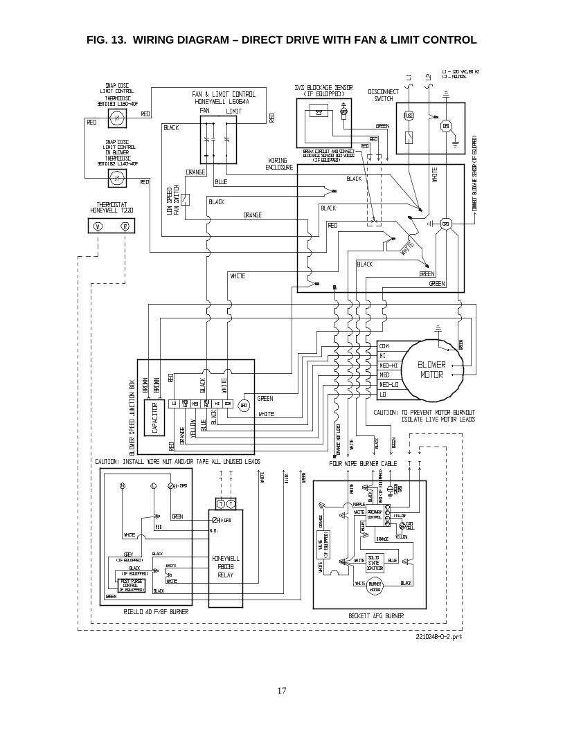
COMBUSTION AND VENTILATION AIR
Free air for ventilation must be permanently provided to the furnace room. Combustion air refers to thetotal air requirements of the fuel-burning appliance. This includes air for the combustion process and airto provide chimney draft (dilution air) for units not equipped with Newmac SVS system. Ventilation airprovides free circulation of air in the room where the appliance is located to keep ambient temperatureswithin safe limits under normal conditions.
Furnaces installed in tight houses, in houses which have air-handling devices with unbalanced airflows, orin enclosed spaces are very likely to have homeowners complain of smoke, fumes, burner lockouts, andexcessive fuel consumption. This is more prevalent in post 1985 construction due to the tighter buildingconstruction as prescribed by the latest building codes. Regulations are relatively specific on theminimum allowable quantities of ventilation and combustion air required once the space category isdetermined. However, every house is subject to different internal and external conditions and regulationsvary among localities. With this in mind, Newmac recommends provision for combustion and ventilationair as specified in Table 5. Table 5 is based on relevant commonly available codes and regulations.
Values indicated in Table 5 are based on the maximum input rating for this single appliance. However, inmaking combustion and ventilation analysis the aggregate input rating of all appliances in the space mustbe considered. The installation of additional oil-fired appliances may require more combustion andventilation air. When sizing combustion and ventilation air ducts, allowance must also be made for theblocking effect of louvers, grilles and screens. If the design and free area is unknown, wood louversgenerally have 20-25% free area and metal louvers or grilles have 60-75% free area. Screens should notbe less than 1/4 inch mesh.
CadCell
TTFF
Limit
Motor
Ignition
WMO-1 Primary Control
Connect WMO-1 atappliance junction box
CL series combination furnaces:Connect WMO-1 at the burnercontrol junction box
(except CL series)
Burner
N

8
TABLE 5. COMBUSTION & VENTILATION AIR SIZING
Vertical Ducts & Direct Opening Sizes Horizontal Duct Sizes (in.)
Free Area L X W(QTY) Dia. (QTY) Free Area L X W (QTY) Dia. (QTY)APPLIANCE FLOOR AREA
(Square Feet)SPACE
CATEGORY
Total (in.2) (in. X in.) (in.) Total (in.2) (in. X in.) (in.)
More than 725 Unconfined 30 4 X 8 (1) 6 (1) 30 4 X 8 (1) 6 (1)NMP
725 or less Confined 72 4 x 9 (2) 7 (2) 145 4 X 18 (2) 10 (2)
The following should be kept in mind when using Table 5:
For models not equipped with SVS Table 5 allows for 18 to 28 in2 for outside combustion air All applicable codes and regulations must be followed. Free duct area is for ducts and opening to outdoors. Unconfined free area values are based on 1 sq. in per 5,000 Btu/hr of the maximum input rating. Confined free area of vertical ducts is based on 1 sq. in per 4,000 Btu/hr of the maximum input rating. Confined free area of horizontal ducts is based on 1 sq. in per 2,000 Btu/hr of the maximum input
rating. Two openings of equal size are required for confined spaces. Maximum length of run for ducts is 50 ft. Duct size allowances must be made for longer runs. Ducts should be designed or insulated to prevent condensation. If insulating, a minimum insulation
value of R-3 is required. In the case where one opening or duct is specified and combustion and ventilation air is still
inadequate, a second duct may be required. Locate one high and the other low for air circulation.
It is particularly important to duct the cold air as close to the appliance as possible. A means of closingthe air openings when the appliance is not operating may be required. Except for an SVS sealed ventinstallation, outside air ducts should not be connected either to the burner or to the appliance.
Guidelines to determine the need for additional combustion and ventilation air may not be adequate forevery situation. If in doubt, it is advisable to err on the safe side and provide additional air.
Fig. 4 shows a typical appliance installation. In this case there is a furnace and a water heater in anenclosed space--both require ventilation and combustion air which is delivered by the top and bottom airducts.
As long as adequate combustion and ventilation air is supplied, the confined appliance room with ductedair offers several advantages:
The incoming cold air is confined to the furnace room. Therefore, the residence occupants are lesssusceptible to drafts. Cool outdoor air will be tempered by the ambient temperature of the furnaceroom before it enters habitable spaces.
Noise levels may be reduced. The furnace will be less susceptible to combustion spillage and back-drafting in low draft situations
reducing odor and smoke. Moderate amounts of smoke and fumes will be contained and expelledsafely outdoors.
Incomplete combustion of any carbon-based fuel may produce deadly carbon monoxide. Ventilationmay dilute any carbon monoxide produced under abnormal operating conditions.
Adequate air for combustion will help maintain the proper air-fuel ratio. Appliances, which are burningfuel rich, will produce soot and burn excessive fuel. A 1/8 inch thick deposit of soot on the surface ofthe heat exchanger is equivalent to 1 inch of fiberglass insulation.
Modern efficient oil burning appliances tend to be physically smaller than are their predecessors are.As a result, hot surfaces such as those on flue connectors are not as high off the ground or floor asthey used to be. A separate furnace room with a “child proof” door is an important safety precaution.

9
OIL BURNER INS
BURNER CAREThis burner is fully automatic in operation. All adjustmenKeep the burner free from excess dirt and moisture. Fueburner motor has oiler openings, the motor should be givleast two or three times a year. No other parts require lu
CAUTION: Do not use gasoline, crankcase or any oilunit or controls--call the serviceman. Do not attemptaccumulated, when the unit is full of vapor, or whenstart the burner unless the cleanout doors are securethe heating system. Never leave combustible materi
OIL BURNER INSTALLATIONInstall the oil nozzle in the burner firing assembly, and chthe correct electrode settings. These settings are criticalmanufacturers have a gauge available for setting the elechave preset stops to ensure the distance from the nozzledimension) is correct. Set or check the air tube insertionthe distance from the face of the burner-mounting flangeburner on the lugs of the burner plate carefully centering1, GENERAL INSTRUCTIONS for preliminary air setting
BURNER SET-UP AND ADJUSTMENTThe installer must use a suitable draft gauge, smoke testthermometer, 0-200 psi oil pressure gauge, 0-30 in. Hg. vproperly set-up the burner.CAUTION: Do not start the burner unless the blower
1. Turn on supply power and set the thermostat above ro2. Open all oil lines and valves.
WATERHEATER
FIG. 4. APPLIANCE LOCATED IN CONFINED SPACE
TRUCTIONS
ts should be made by a qualified technician.l oil leaks should be tended to immediately. If theen a few drops of SAE 20 non-detergent oil atbrication.
containing gasoline. Do not tamper with theto start the burner when excess oil has
the combustion chamber is very hot. Do notd in place. Do not burn garbage or paper in
als such as paper or rags near the unit.
eck the adjustments. See Fig. 5 and Table 6 forfor proper burner operation. Some burnertrodes. Most burners with adjustable headsface to the face of the retention head (“Z”depth according to Fig. 6 and Table 6. This isto the face of the retention head. Mount the oilit in the combustion chamber port. Use TABLEs for the burner.
er, carbon dioxide tester, 0-750°F stackacuum gauge, and 0-220°F thermometer to
access door is secured in place.
om temperature.
WITH ALL AIR FROM OUTDOORS

10
3. Make sure the oil pump by-pass plug is correctly installed for a one or two pipe system. Bleed any airfrom the oil pump (refer to pump manufacture's instructions).
4. Refer to the Certification Label and TABLE 1, GENERAL INSTRUCTIONS for burner adjustments.If the burner fails to start, check (a) oil supply, (b) ignition electrodes and transformer, (c) cad cell.If the burner goes off on safety, do not push the reset button on the primary control for at least 10minutes.Do not push the reset button more than once before correcting the cause. If the burner still doesnot start, press the reset on the burner motor.
5. For units connected to chimney vent, using a suitable draft meter, adjust the barometric draft regulatorto measure the specified flue pressure. This requires that a 5/16" diameter sampling hole be madebetween the flue collar and the draft regulator.
EXTENDED SHUT DOWN PERIODSWhen the appliance is not to be used for an extended period of time, set the thermostat at its lowestvalue, turn off the main switch and close the oil burner supply valve. If the heating unit room is damp,protect the burner against dirt and moisture with a light cover. To resume operation, remove the coverand inspect the burner. Remove any dirt and debris gently to avoid the need to adjustment the air band.Open the supply valve and turn on the main switch. If the burner fails to operate, see the MAINTENANCE& SERVICE section of this manual.CAUTION: Always keep the valve shut if the burner is shut down for an extended period of time.
FIG. 5. ELECTRODE SETTINGS
FIG. 6. BURNER INSERTION TABLE 6. DIMENSIONAL RELATIONSHIPS (Figs 6 & 7)
OIL FILTERUse a 10 micron or better filter. We recommend General FGarber Model 11BV-R. The oil filter should be cleaned or rserviceman.
Z
A
B
C
E
Riello 40F3 or BF3 Beckett AFGA 5/32” 5/32”B 13/64” 7/16”C 5/64” to 7/64” 1/16”Z Refer to Turbulator Setting 1-1/8”
ilters Model GF-CGF10 (refill GF-K10GF) oreplaced at least once a year by the
E 4-5/8” 5”

11
OIL PUMP AND FUEL SYSTEMMake sure the by-pass plug is correctly located for a one or two pipe system. Failure to do so maydamage the pump. Generally, for 3/8” copper tubing, the vertical lift should not exceed 8 feet and thehorizontal run should be limited to 30 feet. Do not exceed 10 psi inlet line pressure.
Single pipe systems are recommended for gravity feed or when the tank outlet is at a higher elevationthan the pump inlet. Refer to Fig. 9. The inlet vacuum should be no more than 6" Hg.
Two pipe systems are recommended for lift feed or when the pump inlet is at a higher elevation than thetank outlet. Install the return line termination higher than the supply intake as shown in Fig. 9. Generally,the inlet vacuum should be no more than 12" Hg.
Correct piping is critical to long-term operation of the fuel system. Never use compression fittings.Minimize the resistance to flow due to excessive line lengths; high lift; and unnecessary fittings, kinks andbends. This will decrease the running vacuum and the risk of air separation. A “Tigerloop” fuel oildeaerator may improve the performance of poorly designed fuel oil delivery systems.
BURNER OIL PRESSURE CHECKInstall the pressure gauge directly on the gauge or nozzle port. Adjust to the pressure specified byNewmac for the nozzle input rating. Refer to TABLE 1,GENERAL INSTRUCTIONS in this manual or thecertification label on the appliance.
Each oil burner should have its own suction line. A common return line can be used as long as thediameter is large enough. Check valves are not required on properly installed systems. Service on fuelunits should not be attempted without a suitable vacuum and pressure gage.
The oil piping information presented here is intended as a guide only. For piping system designdata, consult the installation instructions from the pump manufacturer.
FURNACE SET UP AND MAINTENANCE
BLOWER MOTORSMotor manufacturers supply some motors that do not require oiling. Oil ports usually have plastic coversand are found on the motor end caps. If oil ports are not incorporated, oiling is not required. For motorswith provision for re-oiling use SAE 20 non-detergent oil or oil specially formulated for electric motors.Use only a few small drops two or three times a year.
COMBUSTION CHAMBERMake sure the cerafelt combustion chamber was not damaged or mis-aligned during shipping. Inspectthe combustion chamber periodically and replace if necessary.
SMOKE BAFFLESFour smoke baffles are factory installed. Refer to Fig. 15 and Table 9 for their location.
GAUGE PORT
INLET PORT
BLEED PORT
INLET PORT RETURN & BY-PASS PORT
NOZZLE PORT
FIG. 7. TYPICAL OIL PUMP FIG. 8. RIELLO SLEEVE POSITION
Insertionto flange (TF)
Part No. 2030016Riello Burner End Cone Protector
Setback 0-1/4" Gasket
Riello BF3Riello 40F3

12
Check to ensure they have not become dislodged during shipping. They can be checked andrepositioned, if necessary, by reaching in through the breech pipe and pushing them down the tubes sotheir stop tabs are flush against the welds.
AIR FILTER RACKFilter racks are shipped with the furnace for mounting on both sides. Knockouts are provided at thecorners to cut the opening. The opening in the rack for sliding in the filters should face the front of thefurnace, unless there is enough clearance at the rear to change the filters without damage — at least 24inches. One filter rack can be installed on the bottom. Two return air ducts must be used.
AIR FILTERSAir filters should be inspected monthly and changed as required. At least two changes are usuallyrequired during the heating season—more may be necessary if dusty conditions exist. Remove the filtergently to prevent dust spillage. Install filters of the same size and type. Check filter markings for correctorientation. Two filters must be used
BLOWER REMOVALDisconnect power before removing or servicing the blower.Remove the burner and blower access panels on the front of the furnace. Remove the nut and bolt thatfastens the blower locking plate to the fan partition and slide the blower locking plate out. The blower ismounted on slide rails which allow it to be pulled forward for servicing. The wiring harness has sufficientlength so that it can be removed without disconnecting the motor leads. If the capacitor leads need to beremoved, short the terminals with an insulated screwdriver before handling.
BLOWER ADJUSTMENTThis unit is designed for a maximum temperature rise through the furnace of 85o F at a maximum externalstatic pressure of 0.50 inches of water column. However, due to the wide range of static pressures in ductsystems, it is the responsibility of the installer to verify that the temperature rise does not exceed 85o F. Tomeasure the actual temperature rise let the unit operate for at least five minutes. Insert a thermometerand note the temperature of the warm air supply at a point at least 24 inches from the heat exchangersurface. Next measure the temperature at the return air grill and take the difference. Air temperature risecan be lowered by increasing the blower speed; lowering the firing rate; or increasing undersized supplyand return air free area. The furnace will not operate properly and its life will be decreased if insufficientair quantity passes over the heat exchanger. Similarly, too much air during heating mode resulting in atemperature rise of less than 65o F may cause heat exchanger degradation due to condensation.
DIRECT DRIVE BLOWERThe installer should select the best speed tap for the specific installation. Recommended speed taps forheating are given in TABLE 1, GENERAL INSTRUCTIONS. The motor RPM will vary over a range ofstatic pressures. The blower heating speed can be changed by moving the black wire harness lead toanother speed tap on the terminal block located inside the blower compartment. Refer to TABLE 2,BLOWER PERFORMANCE for airflow data. A second speed for non-heating modes can be selectedusing the red wire harness lead. See FIG. 13 and 14 for WIRING SCHEMATICS.
MAINTENANCE & SERVICE
Maintenance and servicing must be done by a qualified burner technician or shortened furnace life andpoor efficiency may result. Under Tests and Observations and Requirements in CSA B139, the installer isrequired to perform tests to ensure proper and safe operating conditions. Newmac requires the installer tofill out the INSTALLER INFORMATION sheet found in this manual.
CLEANINGThe heat exchanger should be inspected on an annual basis. If cleaning is required, remove the cleanoutcover. Use a wire brush or cleaning tool (available from Newmac) to loosen scale and soot and a vacuumcleaner to remove it from the furnace. Replace gaskets if necessary before replacing the cleanout cover.A layer of soot on the heat exchanger surfaces and firetube walls will reduce heat transfer and canincrease fuel consumption significantly. A 1/32” layer of soot acts as an insulator and can result in a 3%increase in the amount of oil burned. A 1/16” layer may result in an average fuel loss of 8%.

13
When removing the burner, cleanout or cover panels take care not to damage gaskets.Take care not to break the combustion chamber. Removal of the combustion chamber plate assemblyallows a more thorough inspection and cleaning. Replace all parts properly before starting the appliance.
WARRANTY
The following information is required to process warranty claims: owner’s name and address; furnaceserial number, model number, installation date; and installer’s name, address and phone number. A“Returned Goods Number” must be issued by Newmac prior to acceptance of returned goods. Refer tothe LIMITED LIFETIME WARRANTY for terms and conditions
FIG. 9. TYPICAL OIL TANK PIPING INSTALLATIONS
.

14
FIG. 10. DIMENSIONS & CONTROL LOCATION
15
FIG.11. HIGH LIMIT SAFETY CONTROL LOCATIONS

16
FIG. 12. WIRING DIAGRAM – MODELS EQUIPPED WITH FAN TIMER CONTROL
17
FIG. 13. WIRING DIAGRAM – DIRECT DRIVE WITH FAN & LIMIT CONTROL

18
FIG. 14. WIRING DIAGRAM – DIRECT DRIVE WITH FAN & LIMIT CONTROL & FAN CENTER

19
TABLE 7. DUCT SIZING FOR HEATING WITHOUT A/C COILMin. Number Supply Runs
@ 600 FPM Minimum Size
OutputCapacity
(See Notes)
Min. AirFlow Req’d.
Supply Duct orExtended Plenum
@ 800 FPM
Min. Sq. InchNeeded forSpec. CFM
(Total Area ofAll Supply Duct) 5”
Ru
ns
80C
FM
6”R
un
s11
5C
FM
7”R
un
s15
5C
FM
3½
X14
”17
0C
FM Return Duct
Furnace orAir Handler@ 800 FPM
Return Air Grille(or equivalent)
@ Face Velocityof 500 FPM
45,000to
55,000
500CFM
14” X 8”or
12” round100 7 5 4 3
14” X 8”or
12” round12” X 12”
60,000to
70,000
700CFM
18” X 8”or
14” round140 10 6 5 4
18” X 8”or
14” round24” X 10”
75,000to
85,000
800CFM
22” X 8”or
14” round170 10 7 5 5
22” X 8”or
14” round24” X 12”
95,000to
105,000
900CFM
24” X 8”or
15” round190 12 8 6 6
24” X 8”or
15” round24” X 12
105,000to
115,000
1100CFM
22” X 10”or
16” round220 - 10 7 7
22” X 10”or
16” round30” X 12”
125,000to
150,000
1400CFM
24” X 12”or
18” round280 - 12 9 8
24” X 12”or
18” round30” X 14”
155,000to
160,000
1600CFM
1 - 35” X 10” or20” round or2 – 22” X 8”
360 - 14 10 1032” X 10”
or20” round
30” X 18”
165,000to
170,000
1800CFM
1 - 35” X 12”or
2 - 22” X 10”420 - 16 12 11 32” X 12” 30” X 20”
175,000to
190,000
2000CFM
1 - 35” X 14”or
2 - 22” X 12”480 - 18 13 12 32” X 14” 30” X 22”
Notes: 1. BTUH with maximum temperature rise.2. Gas furnaces are rated in input capacity. Rated output capacity is 80 % of input.3. Oil and electric furnaces are rated in output capacity.
TABLE 8. DUCT SIZING FOR HEATING & COOLING WITH A/C COIL IN DUCTAir conditioning systems should never be sized on the basis of floor area alone. Knowledge of the approximate floor area (sq. ft.)that can be cooled with a ton of air conditioning will be of invaluable assistance to you in avoiding serious mathematical errors.
FurnaceMin. Number Supply Runs
@ 600 FPM
Size ofO.D. Unit
Normal AirFlow Req’d@ 400 CFM
per TonBlower
Motor H.P.Blower WheelDia. X Width
SupplyDuct or
Extended Plenum@ 800 FPM
5”R
un
s80
CF
M
6”R
un
s11
5C
FM
7”R
un
s15
5C
FM
3½
X14
”17
0C
FM
Min. Return DuctSize at Furnaceor Air Handler
@ 800 FPM
Min. ReturnAir Grille Size(or equivalent)
@ FaceVelocity of500 FPM
1 ½ ton18,000BTUH
600CFM 1/4 HP 9” X 8”
10” X 8”
16” X 8”or
12” round8 5 4 4
16” X 8”or
12” round24” X 8”
2 ton24,000BTUH
800CFM 1/4 HP 9” X 9”
10” X 8”
22” X 8”or
14” round10 7 5 5
22” X 8”or
14” round22” X 12”
2 ½ ton30,000BTUH
1000CFM 1/3 HP
10” X 8”10” X 10”12” X 9”
20” X 10”or
16” round13 9 7 6
20” X 10”or
18” round30” X 12”
3 ton36,000BTUH
1200CFM 1/3 HP
10” X 8”10” X 10”12” X 9”
24” X 10”or
18” round- 11 8 7
24” X 10”or
18” round30” X 12”
3 ½ ton42,000BTUH
1400CFM
1/2 HP3/4 HP
10” X 8”10” X 10”12” X 9”
12” X 10”
24” X 12”or
18” round- 12 9 8
24” X 12”or
18” round30” X 14”
4 ton48,000BTUH
1600CFM
1/2 HP3/4 HP
12” X 7”12” X 9”
12” X 10”12” X 12”
32” X 10”or
20” round- 14 11 10
32” X 10”or
20” round30” X 18”
4 ½ ton54,000BTUH
1800CFM
3/4 HP1 HP
12” X 8”12” X 9”
12” X 10”12” X 12”
32” X 10”or
20” round- 16 12 11
32” X 12”or
22” round30” X 20”
5 ton 2000CFM
3/4 HP1 HP
12” X 10”12” X 12”
32” X 10”or
20” round- 18 13 12 32” X 14” 30” X 22”

20
FIG. 15. NMP EXPLODED ASSEMBLY
21
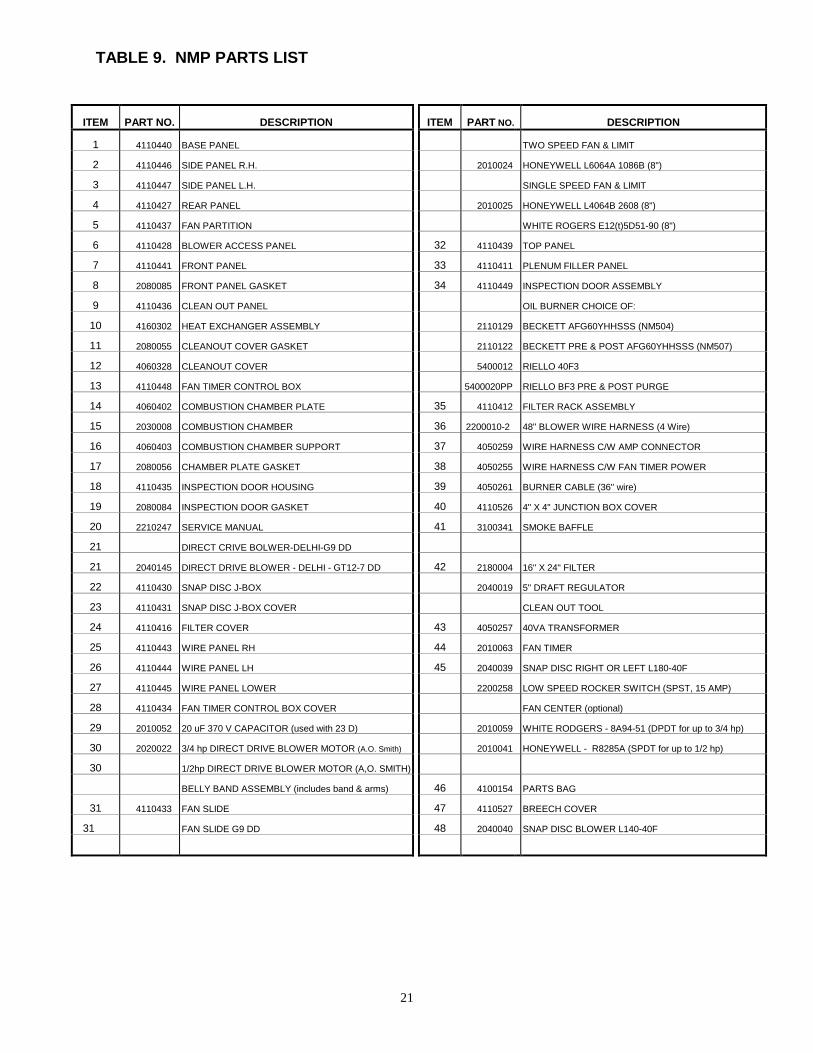
TABLE 9. NMP PARTS LIST
ITEM PART NO. DESCRIPTION ITEM PART NO. DESCRIPTION
1 4110440 BASE PANEL TWO SPEED FAN & LIMIT
2 4110446 SIDE PANEL R.H. 2010024 HONEYWELL L6064A 1086B (8")
3 4110447 SIDE PANEL L.H. SINGLE SPEED FAN & LIMIT
4 4110427 REAR PANEL 2010025 HONEYWELL L4064B 2608 (8")
5 4110437 FAN PARTITION WHITE ROGERS E12(t)5D51-90 (8")
6 4110428 BLOWER ACCESS PANEL 32 4110439 TOP PANEL
7 4110441 FRONT PANEL 33 4110411 PLENUM FILLER PANEL
8 2080085 FRONT PANEL GASKET 34 4110449 INSPECTION DOOR ASSEMBLY
9 4110436 CLEAN OUT PANEL OIL BURNER CHOICE OF:
10 4160302 HEAT EXCHANGER ASSEMBLY 2110129 BECKETT AFG60YHHSSS (NM504)
11 2080055 CLEANOUT COVER GASKET 2110122 BECKETT PRE & POST AFG60YHHSSS (NM507)
12 4060328 CLEANOUT COVER 5400012 RIELLO 40F3
13 4110448 FAN TIMER CONTROL BOX 5400020PP RIELLO BF3 PRE & POST PURGE
14 4060402 COMBUSTION CHAMBER PLATE 35 4110412 FILTER RACK ASSEMBLY
15 2030008 COMBUSTION CHAMBER 36 2200010-2 48" BLOWER WIRE HARNESS (4 Wire)
16 4060403 COMBUSTION CHAMBER SUPPORT 37 4050259 WIRE HARNESS C/W AMP CONNECTOR
17 2080056 CHAMBER PLATE GASKET 38 4050255 WIRE HARNESS C/W FAN TIMER POWER
18 4110435 INSPECTION DOOR HOUSING 39 4050261 BURNER CABLE (36" wire)
19 2080084 INSPECTION DOOR GASKET 40 4110526 4" X 4" JUNCTION BOX COVER
20 2210247 SERVICE MANUAL 41 3100341 SMOKE BAFFLE
21 DIRECT CRIVE BOLWER-DELHI-G9 DD
21 2040145 DIRECT DRIVE BLOWER - DELHI - GT12-7 DD 42 2180004 16" X 24" FILTER
22 4110430 SNAP DISC J-BOX 2040019 5" DRAFT REGULATOR
23 4110431 SNAP DISC J-BOX COVER CLEAN OUT TOOL
24 4110416 FILTER COVER 43 4050257 40VA TRANSFORMER
25 4110443 WIRE PANEL RH 44 2010063 FAN TIMER
26 4110444 WIRE PANEL LH 45 2040039 SNAP DISC RIGHT OR LEFT L180-40F
27 4110445 WIRE PANEL LOWER 2200258 LOW SPEED ROCKER SWITCH (SPST, 15 AMP)
28 4110434 FAN TIMER CONTROL BOX COVER FAN CENTER (optional)
29 2010052 20 uF 370 V CAPACITOR (used with 23 D) 2010059 WHITE RODGERS - 8A94-51 (DPDT for up to 3/4 hp)
30 2020022 3/4 hp DIRECT DRIVE BLOWER MOTOR (A.O. Smith) 2010041 HONEYWELL - R8285A (SPDT for up to 1/2 hp)
30 1/2hp DIRECT DRIVE BLOWER MOTOR (A,O. SMITH)
BELLY BAND ASSEMBLY (includes band & arms) 46 4100154 PARTS BAG
31 4110433 FAN SLIDE 47 4110527 BREECH COVER
31 FAN SLIDE G9 DD 48 2040040 SNAP DISC BLOWER L140-40F

22
FIG. 16. RIELLO BURNER MODEL 40 F3 EXPLODED ASSEMBLY
FIG. 17. RIELLO BURNER MODEL 40 BF3 EXPLODED ASSEMBLY
Item 2030016 Riello Burner End Cone Protector not shown. See Fig. 9 for its location.

23
TABLE 10. RIELLO BURNER PARTS LIST
ITEM PART NUMBER BURNERMODEL
DESCRIPTION
F3 BF3 RIELLO NEWMAC F3 BF31 3006911 2090055 X Hydraulic jack2 3006912 X Capillary tube3 3000878 X Hydraulic air shutter4 34 3005708 X X Fan5 33 3005844 2090041 X X Capacitor 12.5 uF6 3006993 X Pipe connector-return7 3005847 X 1/4" NPT/metric adapter-female8 3006992 X Pipe connector-supply9 3006571 X 3/8" NPT/metric adapter-male10 2 3007077 X X Crushable metal washer 3/8" ID11 4 3007028 X X O-ring - pump pressure regulator12 6 C7010002 2090043 X X O-ring - pump cover13 7 3005719 X X Pump screen14 8 3006036 X X Valve stem15 10 3007029 X X O-ring valve stem,upper16 11 3007156 X X O-ring valve stem,lower17 12 3007268 X X Nozzle outlet fitting18 14 3006553 X X Coil U-bracket retainer nut19 15 3002279 X X Coil20 16 3007802 2060007 X X Pump21 17 3000443 X X Pump drive key22 18 3005843 X X Motor23 9 3007203 X X Plate - valve stem retainer24 20 3002278 X X Primary control sub-base25 21 3001157 2010048 X X Primary control 530 SE/C26 22 3002280 2010045 X X Photo cell27 3005854 X Semiflange (2 Req'd)28 24 3005855 X X Universal mounting flange29 25 3005856 2080058 X X Mounting gasket30 5 N/A X Regulator31 19 3007315 X X Air tube cover plate
3007316 Air tube cover plate32 3007221 X Chassis front plate
3007222 Air intake housing33 3007204 X Manual Air Shutter34 32 3007207 X X Air intake housing
3007208 Air intake housing32 3007824 Air intake housing
35 3007232 X Burner back cover3007233 Burner back cover

24
TABLE 10. RIELLO BURNER PARTS LIST – continued
ITEM PART NUMBER BURNERMODEL
DESCRIPTION
F3 BF3 RIELLO NEWMAC F3 BF31 3008019 X Burner cover
1 3008023 Burner Cover36 3007319 X Acoustic liner
3007320 Acoustic liner37 13 3007087 X X Crushable metal washer 5/8" ID40 40 3948873 2210141 X X Short combustion head - 6"
40 3948973 2210143 Short combustion head - 6"41 41 3006968 X X Turbulator disc
41 3006977 Turbulator disc42 42 3006966 X X Electrode support43 43 3006965 X X Nozzle adapter44 44 3006969 X X Nozzle oil tube - short
44 3006973 Nozzle oil tube - short45 45 3006324 X X Regulator assembly - short
45 3006323 Regulator assembly - short46 46 3006330 X X Electrode assembly - short
46 3006329 Electrode assembly - short47 47 3005869 X X Electrode porcelain48 48 3007592 X X End cone assembly - short
48 3007594 End cone assembly - short3 3007568 X X Bleeder23 C5283000 X Electrical fitting26 3008020 X Oil supply tube & adapter fitting26 3008024 Oil supply tube & adapter fitting27 3007901 X Plug29 3007630 X Gasket burner cover30 3000681 X Manual air damper regulator31 3008021 X Air damper35 3007707 X Cover screw and washer36 3007628 X Filter assembly37 3007627 X Plug-cover opening-burner reset
C7001025 2110172 X Two line conversion kitC7001026 2110173 Two line conversion kit3007627 2010044 X Relay, Honeywell R8038A 1048

25
FIG. 18. BECKETT BURNER MODEL AFG60YHHSSS EXPLODED ASSEMBLY
BECKETT BURNER MODEL AFG60HYYSSS PARTS LIST
PART NUMBER BURNER MODELAFG60HYSSSITEM
BECKETT NEWMACNM504 / NM507
DESCRIPTION
1 5877 2090024 X Burner Housing Assembly2 3709 X Air Shutter3 3492 X Air Band4 3493 X Escutcheon Plate
5941 X Adjusting Plate Assy7 2456 2020012 X Motor, 1/7 hp, 3450 RPM
2020019 X Motor, 1/7 hp, #PSC21805U9 2999 2090056 X Blower Wheel10 2454 2090011 X Flexible Coupling11 2060004 X Pump
51573 2090058 Suntec Pump c/w Soilenoud Valve12 2256 Pump Nozzle Port Fitting13 5636 Connector Tube Assembly14 2442 2090025 X Ignition Transformer (10,000 Volt)
51771U 2090064 X Electronic Ignitor (14,000 Volt)17 3708 2090044 X Low Firing Rate Baffle18 2090047 X 6” Electrode Assembly21 5770 X Junction Box Kit26 3-666 X Knurled Locknut27 2-13 X Nozzle Adapter – Single28 1-49 X Electrode Clamp36 3384 X 3-3/8U Static Plate47 2110006 X End Cone, F3
31517 2110015 X Ceramic Heat Shield2110016 X Ceramic Heat Shield Holder
48 2090040 6” SS Air Tube c/w Welded Flange49 7022 2010002 X Primary Relay, R7184A
7424 2090057 Primary Relay, R7184P3416 2080051 X Flange Gasket51770 2090061 Field Controls AirBoot7006 2010006 X Cad Cell C554A1455B Honeywell
2100130 Nozzle, Delavan 0.65 X 70º A2100131 Nozzle, Delavan 0.75 X 70º A2100128 X Nozzle, Delavan 0.85 X 70º A2100132 Nozzle, Delavan 1.00 x 70º A

26
FIGURE 19. COMMON CHIMNEY DRAFT PROBLEMS

27
FIGURE 20. TROUBLESHOOTING CHARTPROBLEM CAUSE CORRECTION
Thermostat Check for Broken WiresTighten ConnectionsClean Contacts
Burner Motor Fails to Start Replace ThermostatBurner Motor Overload Tripped Press Rest ButtonCeased Pump Repair or ReplaceFaulty Primary Relay Repair or Replace
Oil Supply Check Oil SupplyAir Leak in Oil Supply Line Tighten Fittings or Replace LineOil Line Plugged or Kinked Clean or RepairOil Filter Clogged Replace or CleanLoss of Prime Eliminate Teed Oil Lines
Burner Start--No Flame Electrode Setting Adjust ElectrodesLoose or Dirty Nozzle Replace NozzleIgnition Transformer Replace TransformerBurner Motor Overload Trips Press Rest ButtonCeased Pump Repair or ReplaceFaulty Primary Relay Repair or Replace
Cad Cell Clean or ReplaceOil Line Restricted Clear RestrictionPlugged Fuel Pump Clean Strainer
Burner Locks out on Safety Loss of Prime Eliminate Teed Oil LinesCold Oil Change to #1 Oil
Convert to One Line SystemPoor Combustion Adjust Air Settings
Ensure Draft is Adequate
Air Leak in Oil Supply Line Tighten Fittings or Replace LineLoose or Dirty Nozzle Replace NozzleFaulty Oil Pump Repair or Replace PumpOil Supply Line Ensure Properly DesignedLoss of Prime Eliminate Teed Oil Lines
Burner Ignition Delayed Electrode Setting Adjust ElectrodesCracked Electrodes Replace ElectrodesWrong Nozzle Use Specified NozzleLow Oil Pressure Adjust to Correct SettingExcess Air Adjust Air SettingFaulty Transformer Replace Transformer
Insufficient Combustion Air Provide Combustion AirInadequate Flue Draft Provide Specified DraftPump Seal Leaking Repair PumpLoss of Prime Eliminate Teed Oil LinesNozzle Assembly Adjustment Ensure Setting is CorrectBurner Adjustment Check Using Instruments
Fumes & Odors From Burner Blast Tube Burned Off Check Blast TubeEnd Cone Wrong or Burned Off Check End ConeIncorrect Insertion Measure Insertion DepthDirty Burner Fan Clean BladesDamaged Chamber Check ChamberClogged Flue Passages Clean Flue PassagesNozzle After Drip Check Fuel Delivery SystemUnspecified Nozzle Replace Nozzle
FIGURE 20. TROUBLESHOOTING CHART-continued

28
PROBLEM CAUSE CORRECTIONFiring Rate Too Low Use Higher Input NozzleDirty Heat Exchanger Clean Heat Exchanger
Not Enough Heat Poor Combustion Adjust Using InstrumentsUndersized Capacity Size Based on Heat LossDistribution System Ensure Proper DesignFaulty thermostat or Location Repair, Replace, or Relocate
Defective Primary Control Repair or ReplaceFaulty Thermostat or Location Repair, Replace, or Relocate
Too Much Heat Faulty Oil Pump Check for Proper PressureFiring Rate Too High Reduce Nozzle SizeOversized Capacity Size Based on Heat LossDistribution System Proper Duct Design
Poor Combustionl Adjust Using InstrumentsExcess Air Adjust Air SettingInadequate Flue Draft Provide Specified Draft
Excessive Oil Consumption Insufficient Combustion Air Provide Combustion AirOil Supply Check Oil SupplyElectrode Setting Adjust ElectrodesWrong Nozzle Use Specified NozzleFuel System Leaking Check Fuel SystemFaulty Oil Pump Repair or Replace Pump
Over-Firing Use Specified Nozzle SizeReplace Dirty FiltersIncrease Blower SpeedIncrease Undersized R/A DuctsClear Blocked Return RegistersIncreased Undersized S/A Ducts
Short Cycling Clear Blocked Supply GrillsReplace Faulty Blower MotorClean Clogged Blower Wheel
Tripping High Limit
Replac Broken Blower BeltFaulty Thermostat or Location Repair, Replace, or RelocateHeat Anticipator Set Too Low Adjuct Heat AnticipatorDefective Primary Relay Repair or Replace Relay
Burner Pump Whine Eliminate Suction Line Air LeakNoise Duct Expansion Stiffen Plenum & Ducts
Plenum Amplifies Noise Install Plenum Apron
Blocked Flue Passages Clean BoilerUnspecified Burner Replace BurnerUnspecified Nozzle Install Correct NozzleIncorrect Head Install Correct HeadWrong / Misaligned Static Plate Install Correct Plate or Align
Burner Air Tube Burn-Off Chimney Down Draft Install Chimney CapIncrease Draft at BreechPoor Over-Fire DraftCorrect Chimney ProblemsUse Specified NozzleOver-FiringUse Specifed PressureUse Correct Air Tube AssemblyIncorrect InsertionAdjust Flange
Reduced Draft Add Combustion AirDelayed Ignition Adjust Burner Settings
Frequent Sooting Loss of Prime Eliminate Teed Oil LinesUnspecifed Burner Replace BurnerUnspecified Nozzle Install Correct NozzleIncorrect Head Install Correct Head
Reduce Motor SpeedPremature Corrosion Temperature Rise Too Low Use Higher Specified Nozzle

29
INSTALLER INFORMATION
NAME:
COMPANY:
INSTALLATION DATE:
THE HOMEOWNER SHOULD TELEPHONE ( ) FOR SERVICE ORADDITIONAL INFORMATION.
MODEL:
APPLIANCE INITIAL TEST AND SERVICE INFORMATION
1 FUEL INPUT (USGPH)
2 FUEL PRESSURE (PSIG)
3 FLUE PRESSURE (INCHES W.C.)
4 OVERFIRE PRESSURE (INCHES W.C.)
5 NOZZLE ANGLE / PATTERN
6 CO2 PERCENT
7 BURNER MODEL
8 FLUE GAS TEMPERATURE (Fº)
9 ROOM TEMPERATURE (Fº)
10 SMOKE NUMBER (BACHARACH)
11 FUEL GRADE NUMBER
12 SUPPLY PLENUM STATIC PRESSURE (INCHES W.C.)
13 SUPPLY AIR TEMPERATURE (Fº)
14 RETURN AIR TEMPERATURE (Fº)
15 AIR TEMPERATURE RISE (Fº)
16 LIMIT CONTROL FUNCTIONING PROPERLY
17 PRIMARY CONTROL SHUT OFF TIME (IGNITION FAILURE)
18 PRIMARY CONTROL SHUT OFF TIME (FLAME FAILURE)

30
IMPORTANT HOMEOWNER INSTRUCTIONS
1. AN EMERGENCY POWER SWITCH IS REQUIRED TO BE INSTALLED IN ACONVENIENT LOCATION AT A SAFE DISTANCE FROM THE BURNER. THISSWITCH INTERRUPTS THE ELECTRICAL SUPPLY CIRCUIT TO THE APPLIANCE.MAKE SURE YOU ARE AWARE OF ITS LOCATION AND THE OFF POSITION ISCLEARLY MARKED.
2. KEEP THE SPACE CLEAR AROUND THE APPLIANCE WITHIN THE SPECIFIEDCLEARANCES TO COMBUSTIBLES.
3. ENSURE THE SUPPLY OF COMBUSTION AIR TO THE APPLIANCE IS NOTOBSTRUCTED OR CUT-OFF.
4. MAINTAIN PROPER VENTILATION OF THE APPLIANCE AREA.
5. MAINTAIN FREE AIR FLOW THROUGH THE RETURN AIR REGISTERS. *
6. CONTACT SERVICE PERSONNEL BEFORE REMODELLING.
7. CONTACT SERVICE PERSONNEL FOR ANNUAL SERVICE AND MAINTENANCE.
8. CONTACT SERVICE PERSONNEL FOR AIR FILTER REPLACEMENT. *
9. CONTACT SERVICE PERSONNEL BEFORE AND AFTER EXTENDED PERIODS OFAPPLIANCE INOPERATION.
10. THE BURNER IS FULLY AUTOMATIC IN OPERATION. ALL ADJUSTMENTSSHOULD BE MADE BY A QUALIFIED TECHNICIAN. DO NOT PUSH THE RESETBUTTON MORE THAN ONCE.
CAUTION : DO NOT ATTEMPT TO START THE BURNER WHEN EXCESS OIL HASACCUMULATED, WHEN THE APPLIANCE IS FULL OF VAPOUR, OR WHEN THECOMBUSTION CHAMBER IS VERY HOT.
11. CAUTION : DO NOT TAMPER WITH THE APPLIANCE OR CONTROLS—CALLYOUR SERVICE PERSONNEL.
12. DO NOT USE GASOLINE, CRANKCASE OIL, OR ANY OIL CONTAINING GASOLINE
13. ALWAYS KEEP THE OIL SUPPLY VALVE SHUT OFF IF THE BURNER IS SHUTDOWN FOR AN EXTENDED PERIOD OF TIME.
14. DO NOT START THE BURNER UNLESS THE BLOWER ACCESS DOOR ISSECURED IN PLACE.
15. NEVER BURN GARBAGE OR PAPER IN THE HEATING SYSTEM, AND NEVERLEAVE PAPER OR RAGS AROUND THE APPLIANCE.
* FURNACES ONLY

31
OIL FIRED FURNACE - LIMITED LIFETIME WARRANTY
Effective July 1, 1995 and subject to the following conditions Newmac Manufacturing Inc. warrants the Oil Fired Furnace, to the original owner purchaser, under normaluse and repair against defects in workmanship and materials for a period of one calendar year from the date of original installation. This warranty does not covernozzles, filters, belts etc.
The burner, blower, motors, controls or any other electrical or mechanical components not manufactured by Newmac are warranted for a period of one year fromdate of original installation by their respective manufacturers; burners 3 years.
Effective July 1, 1995 and on the date of original installation Newmac warrants to the original purchaser during his or her lifetime that the primary heat exchanger ofall Oil Fired Furnaces will be free from defects in material and workmanship provided however, this warranty shall apply only to the original installation of the furnace ina single dwelling unit used without interruption by the purchaser as his or her principal residence. This warranty does not apply to solid fuel or combination furnaces andis subject to the conditions and exceptions of warranty listed below.
Under the above warranty Newmac Mfg. at its option will repair or replace the heat exchanger under the above terms or offer the then current applicable retail priceof a heat exchanger towards a new equivalent furnace. Proof of original purchase will be required.
The warranty must be registered within 30 days of installation or the following pro-rated warranty “Twenty Year Warranty” applies.Where the owner of the dwelling is not the original purchaser and in multi-family dwellings Newmac warrants the primary heat exchanger against defects in materials
and workmanship under a 20 year Limited Warranty subject to the conditions and exceptions listed below and on a prorated basis as follows of the then current retailprice
0-10 Years 100% Warranty 0 of Retail Price11-12 " 50% " 50% "12-14 " 40% " 60% "14-16 " 30% " 70% "16-18 " 20% " 80% "18-20 " 10% " 90% "20 years and over 0% " 100% "
The purchaser must pay all other costs of warranty service including labour costs involving diagnostic calls and or removing, servicing and or replacing warrantyparts and or warehousing charges and or freight costs. All parts are supplied F.O.B. Debert, Nova Scotia and the defective parts must be returned freight prepaid forrepair and or warranty consideration when requested by Newmac Mfg.CONDITIONSThis warranty refers to the primary combustion heat exchanger.In order for this warranty to be effective:1. The furnace must be installed by a qualified licensed installer and in accordance with Newmac’s installation instructions. The furnace must also be installed inaccordance with all applicable, local states, or provincial codes and the National Warm Air Heating and Air Conditioning Association Standards or generally acceptedequivalent standards.2. The Furnace must operate in an environment not contaminated by halogens (such as but not limited to fluorine or chlorine) or chlorinated hydro carbons. Thesecorrosive chemicals entering the combustion area cause rapid deterioration of inner surfaces leading to heat exchanger failures. The furnace must be maintained andcleaned on an annual basis by qualified personnel; air filters should be changed monthly. Oil filters and nozzles must be changed annually.3. The furnace must be sized and fired correctly as stated on the label for the residence. The label must not have been defaced or removed.4. The furnace must not be modified from its published design or purpose and or an air conditioning coil shall not be installed on the return air side of the furnace.5. Furnace must not have been removed from the original installation site.6. There must be adequate return air and or ductwork.7. There must be adequate combustion air installed to the furnace room; and in the case of sidewall venting there must be adequate ventilation air in addition tocombustion air to prevent depressurization of the home.8. Warranty components may be replaced with reconditioned parts at the discretion of Newmac Mfg.9. Proof of original purchase will be requested under this warranty.EXCEPTIONS1. All labour, freight or diagnostic calls, removal and replacement costs and warehousing charges are the responsibility of the purchaser including the return to Debert,Nova Scotia of defective parts.2. Defects or damages caused by failure of the refractory chamber, improper installation, wiring, electrical current characteristics, accident, misuse or abuse, fire, flood,alteration and or misapplication of the product, default or delay in performance; caused by war, government restrictions, restraints, strikes, material or freezing.3. Refractory chamber, nozzles, air filters, belts etc...4. Defects or damages caused by nozzle failure and/or plugging and/or oil flow restrictions due to cold oil from outside tanks or misalignment of burner at installation.5. This warranty in no way can be considered as a guarantee of workmanship of an installer connected with the installation of the Newmac Oil Fired Furnace or asimposing on Newmac any liability of any nature for unsatisfactory performance as a result of faulty workmanship in the installation which liability is expresslydisclaimed.6. This warranty will not be applicable if the furnace is damaged or a result of being improperly serviced or operated.LIMITATIONS ON WARRANTYNewmac will make no express warranties other than the warranty set forth above. All implied warranties including the implied warranties of amerchantability and fitness for a particular purpose are limited to the duration of the express warranty, set forth above. Liabilities for incidental andconsequential damages are excluded regardless of the cause. Some provinces in Canada and some states in the U.S.A. do not allow limitations on howlong an implied warranty lasts so the above may not apply to you. The expressed warranties made in this warranty are exclusive and may not be altered,enlarged or changed by any distributor, dealer or any other person whatsoever. All replacement parts whether new or remanufactured, assume as theirwarranty period on the remaining period of this warranty.For routine service requirements contact the dealer who installed the equipment originally, or an alternate qualified and registered heating dealer or electrical.
To register your warranty, please complete form below, detach and mail to Newmac Mfg. Inc. P.O. Box 9, Lancaster Cr; Debert, N.S. B0M 1G0
LIMITED LIFETIME WARRANTY REGISTRATION
_ _ _ _ _ _ _ _ _ _ _ _ _ _ _ _ _ _ _ _ _ _ _ _ _ _ _ _ _ _ _ _ _ _ _ _ _ _ _ _ _ _ _ _ _ _ _ _ _ _ _ _ _ _ _ _ _ _ _ _ _ _ _ _ _ _ _ _ _ _ _ _ _ _ _ _ _ _Owner’s Name Date of Installation
_ _ _ _ _ _ _ _ _ _ _ _ _ _ _ _ _ _ _ _ _ _ _ _ _ _ _ _ _ _ _ _ _ _ _ _ _ _ _ _ _ _ _ _ _ _ _ _ _ _ _ _ _ _ _ _ _ _ _ _ _ _ _ _ _ _ _ _ _ _ _ _ _ _ _ _ _ _ _ _Address of Installation
_ _ _ _ _ _ _ _ _ _ _ _ _ _ _ _ _ _ _ _ _ _ _ _ _ _ _ _ _ _ _ _ _ _ _ _ _ _ _ _ _ _ _ _ _ _ _ _ _ _ _ _ _ _ _ _ _ _ _ _ _ _ _ _ _ _ _ _ _ _ _ _ _ _ _ _ _ _ _Dealer’s Name Dealer’s Address
_ _ _ _ _ _ _ _ _ _ _ _ _ _ _ _ _ _ _ _ _ _ _ _ _ _ _ _ _ _ _ _ _ _ _ _ _ _ _ _ _ _ _ _ _ _ _ _ _ _ __ _ _ _ _ _ _ _ _ _ _ _ _ _ _ _ _ _ _ _ _ _ _ _ _ _ _ _ _Furnace Serial Number Furnace Model Number