Embed Size (px)
Citation preview

TA0136
USER MANUAL
ARDUINO 2 WHEEL
DRIVE ULTRASONIC
ROBOT KIT
Contents 1. Overview – TA0136 ....................................................................................................................... 3
2. Getting started: Programming the arm robot using Arduino UNO ................................................. 3
2.1. What is Arduino? .................................................................................................................... 3
2.2. What is IDUINO UNO? .......................................................................................................... 3
2.3. What are the differences between other Arduino development boards we are providing? ..... 3
3. Software installation ....................................................................................................................... 4
3.1. Arduino Software/IDE ............................................................................................................ 4
3.2. Play with your first “Hello World” LED example .................................................................. 5
3.3. Run your Arduino 2 Wheel Drive code .................................................................................. 7
4. Hardware installation ...................................................................................................................... 8
4.1. Unboxing and Component list ................................................................................................ 8
4.2. Chassis Frame Installation .................................................................................................... 10
4.3. Arduino Installation .............................................................................................................. 18
4.4. Sensor installation ................................................................................................................. 25
4.5. Switch ................................................................................................................................... 32
4.6. Wire Connection ................................................................................................................... 34
5. Have fun ........................................................................................................................................ 37
Appendix ............................................................................................................................................... 38
1. Overview – TA0136
In this instruction, we will introduce you through the fun project of the Arduino 2 Wheel Drive
Ultrasonic Robot Kit. Get your Arduino board kit. Let’s get started!
2. Getting started: Programming the arm robot using Arduino UNO
2.1. What is Arduino?
Arduino is an open-source electronics platform based on easy-to-use hardware and software. Arduino
boards can read inputs - light on a sensor, a finger on a button, or a Twitter message - and turn it into
an output - activating a motor, turning on an LED, publishing something online. You can tell your
board what to do by sending a set of instructions to the microcontroller on the board. To do so you use
the Arduino programming language (based on Wiring), and the Arduino Software (IDE), based on
Processing.
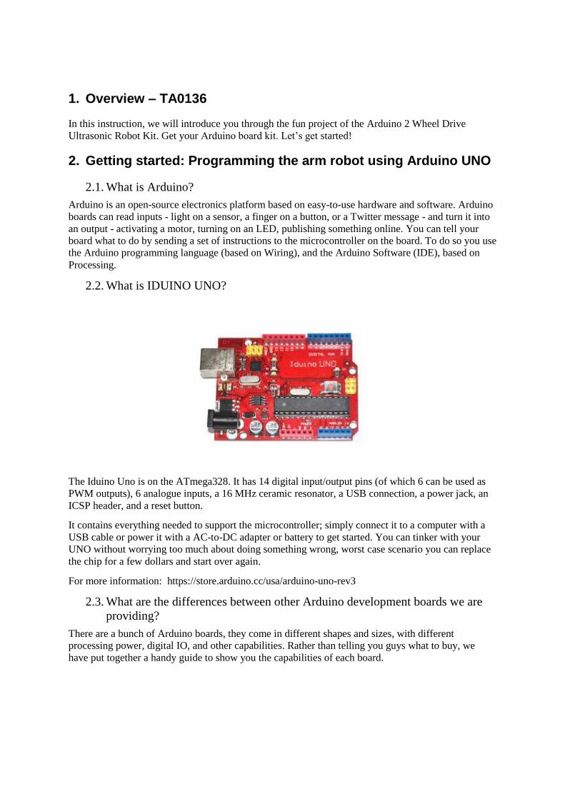
2.2. What is IDUINO UNO?
The Iduino Uno is on the ATmega328. It has 14 digital input/output pins (of which 6 can be used as
PWM outputs), 6 analogue inputs, a 16 MHz ceramic resonator, a USB connection, a power jack, an
ICSP header, and a reset button.
It contains everything needed to support the microcontroller; simply connect it to a computer with a
USB cable or power it with a AC-to-DC adapter or battery to get started. You can tinker with your
UNO without worrying too much about doing something wrong, worst case scenario you can replace
the chip for a few dollars and start over again.
For more information: https://store.arduino.cc/usa/arduino-uno-rev3
2.3. What are the differences between other Arduino development boards we are
providing?
There are a bunch of Arduino boards, they come in different shapes and sizes, with different
processing power, digital IO, and other capabilities. Rather than telling you guys what to buy, we
have put together a handy guide to show you the capabilities of each board.
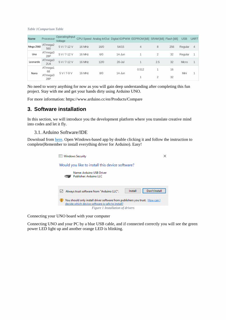
Table 1Comparison Table
No need to worry anything for now as you will gain deep understanding after completing this fun
project. Stay with me and get your hands dirty using Arduino UNO.
For more information: https://www.arduino.cc/en/Products/Compare
3. Software installation
In this section, we will introduce you the development platform where you translate creative mind
into codes and let it fly.
3.1. Arduino Software/IDE
Download from here. Open Windows-based app by double clicking it and follow the instruction to
complete(Remember to install everything driver for Arduino). Easy!
Figure 1 Installation of drivers
Connecting your UNO board with your computer
Connecting UNO and your PC by a blue USB cable, and if connected correctly you will see the green
power LED light up and another orange LED is blinking.
Operating/Input
Voltage
Mega 2560ATmega2
5605 V / 7-12 V 16 MHz 16/0 54/15 4 8 256 Regular 4
UnoATmega3
28P5 V / 7-12 V 16 MHz 6/0 14-Jun 1 2 32 Regular 1
LeonardoATmega3
2U45 V / 7-12 V 16 MHz 12/0 20-Jul 1 2.5 32 Micro 1
ATmega1
680.512 1 16
ATmega3
28P1 2 32
1
SRAM [kB] Flash [kB] USB UART
Nano 5 V / 7-9 V 16 MHz 8/0 14-Jun Mini
Name Processor CPU Speed Analog In/Out Digital IO/PWM EEPROM [kB]

Figure 2 Check Your special COM and note it down the number
Find your Serial COM
number and note it down.
We need to figure out which channel COM is currently communicating between PC and UNO.
Following the path: Control panel | Hardware and Sound | Devices and Printers | Device Manager |
Ports (COM & LPT) | Arduino UNO (COMx)
Note down the COM number as we require this later. In this case, we are using the COM 4
3.2. Play with your first “Hello World” LED example
Firstly, let’s tell IDE where to find our Arduino port and which board you are currently using: The
following instruction (Figure 3 and 4) shows the details:
Configuration of Ports
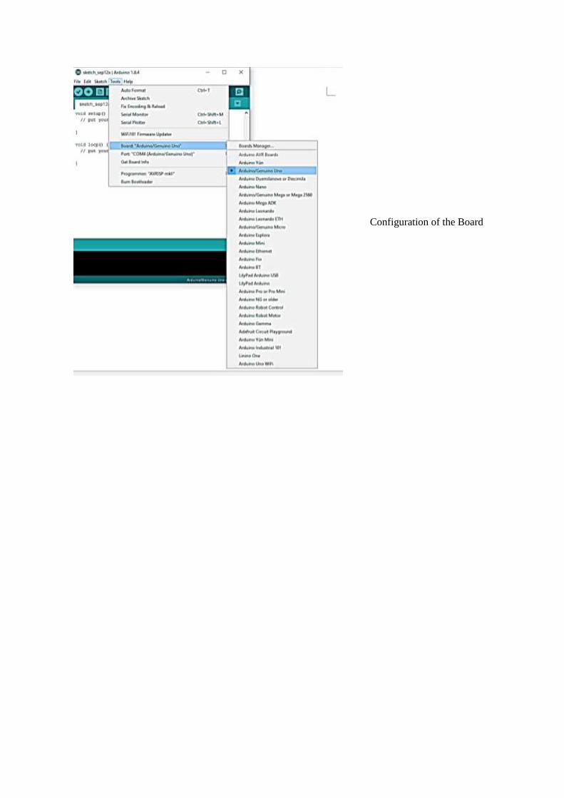
Configuration of the Board
It’s time to play with you first simple example. Following the path by File | Examples | 01. Basics |
Blink. A new code window would pop up, press the arrow symbol to upload. You will notice the
orange LED is blinking almost every second.
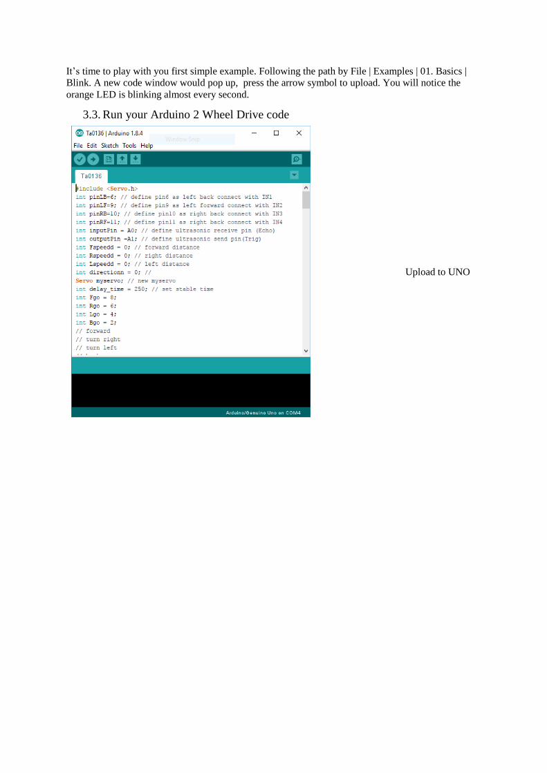
3.3. Run your Arduino 2 Wheel Drive code
Upload to UNO

Done uploading!
4. Hardware installation
4.1. Unboxing and Component list
- Acrylic Chassis
- DC Motors
- SG90 Servo and
Bracket
- Rubber Wheels
- Metal Pivot wheel

- Ultrasonic Sensor
- Arduino UNO
- Sensor shield
- 6 x AA Battery Box
- L298N Board
- Switch
- Fastener package
Screw, nuts and
spacer components
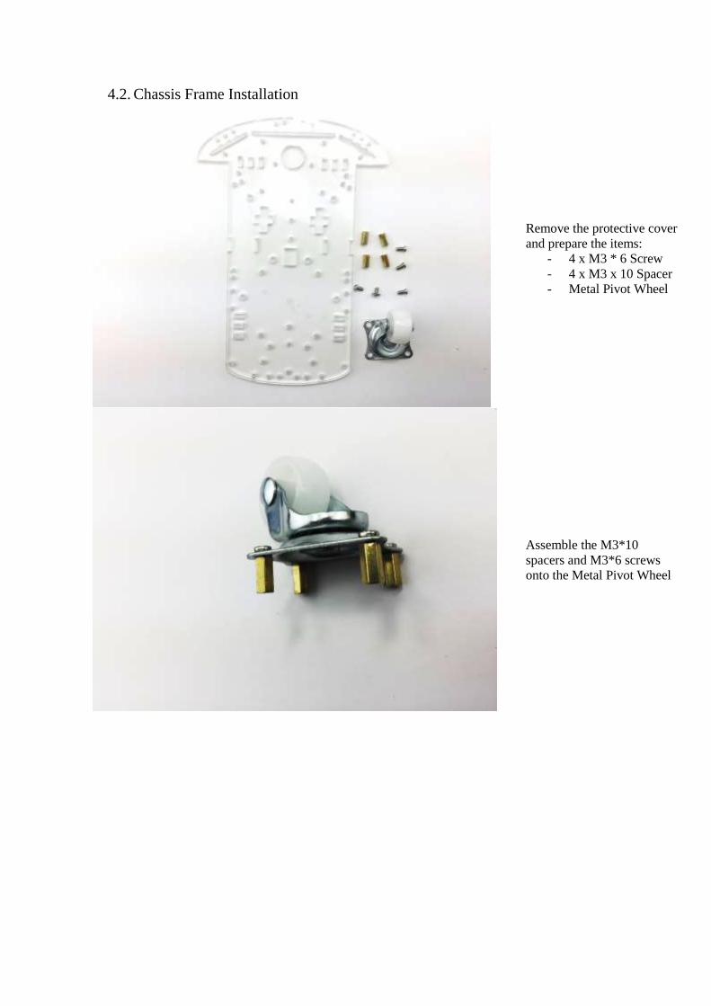
4.2. Chassis Frame Installation
Remove the protective cover
and prepare the items:
- 4 x M3 * 6 Screw
- 4 x M3 x 10 Spacer
- Metal Pivot Wheel
Assemble the M3*10
spacers and M3*6 screws
onto the Metal Pivot Wheel
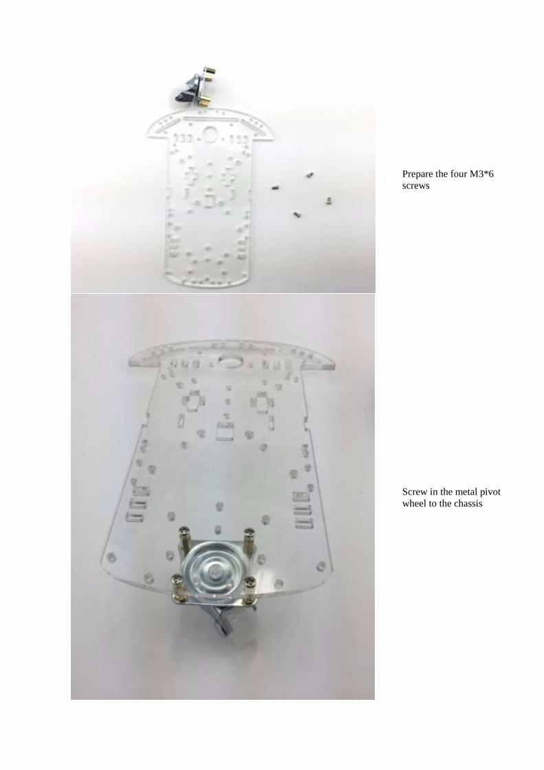
Prepare the four M3*6
screws
Screw in the metal pivot
wheel to the chassis
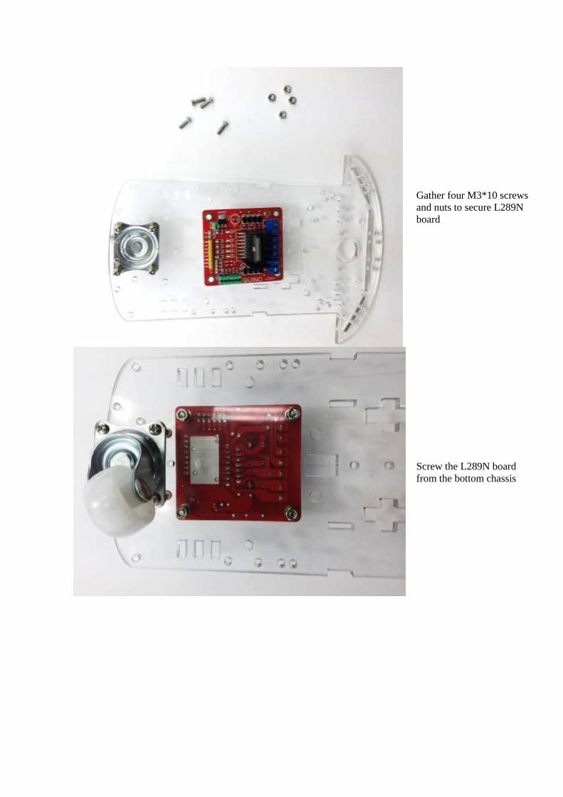
Gather four M3*10 screws
and nuts to secure L289N
board
Screw the L289N board
from the bottom chassis
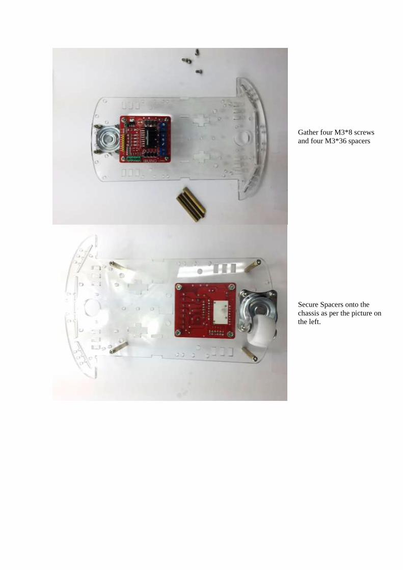
Gather four M3*8 screws
and four M3*36 spacers
Secure Spacers onto the
chassis as per the picture on
the left.

Spacers/Stand-offs should
look like this

Gather the following
components:
- 2 x DC motors
- 2 x Acrylic Motor
Brackets
- 4 x M3*30 screws
and nuts
*Attaching wheel encoders
are optional. These are not
required for this particular
project

Place acrylic DC motor
Brackets on both side of
the motors as shown on the
left
Gather another two acrylic
fasteners and two wheels
and nuts

Insert the acrylic fasteners
first in pre-cut slot
Then tighten and secure the
DC motor with one nut on
the other side

Fix the other motor as well
Pull the wire through as we
need to connect them to the
L289N board
4.3. Arduino Installation
Let’s fix the Arduino UNO and Sensor shield in the following steps.

Prepare the
jumper cables
Separate the jumper
cable set into four and
eight configurations

Connect the 8 jumpers
with L289N board as
shown.
Prepare the following:
- Battery pack
- UNO board
- Top acrylic chassis
6 x nuts
- 6 x M3*10 screws

Peel the protective
cover
Place the battery pack
and UNO board on the
top acrylic chassis
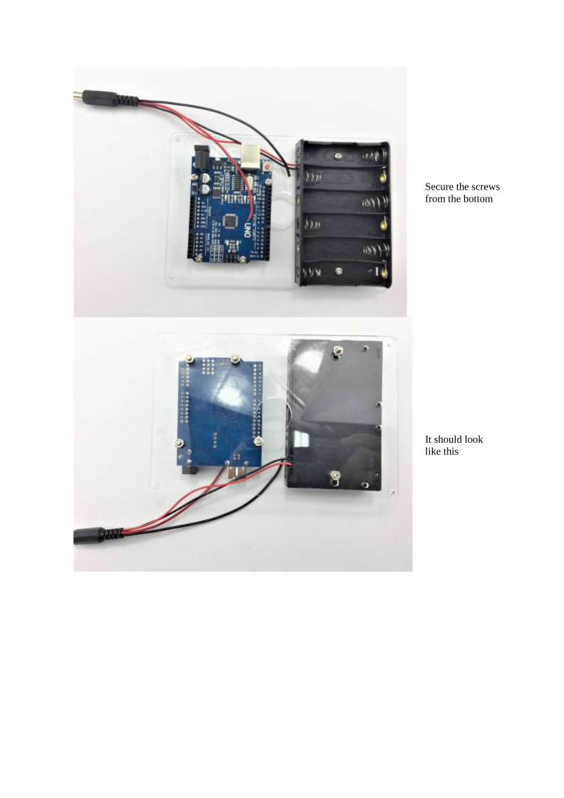
Secure the screws
from the bottom
It should look
like this

Feed the jumper wire
from the L289N board
and pull through to the
top acrylic chassis hole
to connect with the
UNO board later
Mount the top acrylic
chassis to the bottom
chassis

Use four M3*6 screws
to secure top acrylic
chassis.
It should look
like this
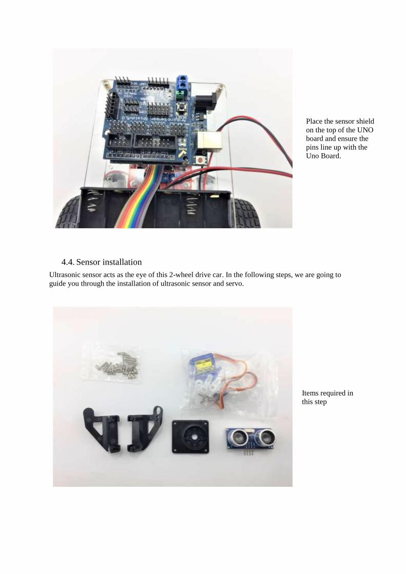
Place the sensor shield
on the top of the UNO
board and ensure the
pins line up with the
Uno Board.
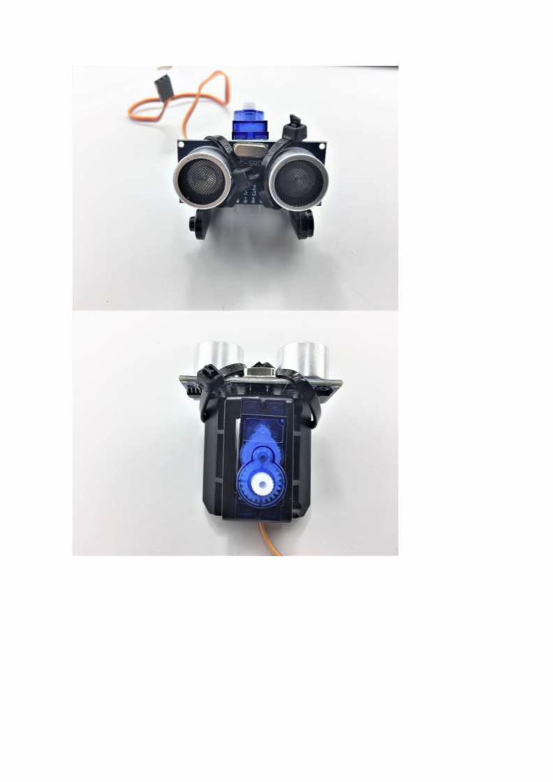
4.4. Sensor installation
Ultrasonic sensor acts as the eye of this 2-wheel drive car. In the following steps, we are going to
guide you through the installation of ultrasonic sensor and servo.
Items required in
this step

Assemble the FPV
holder and servo
Use two self-
tapping screws (in
the FPV package)
to tighten
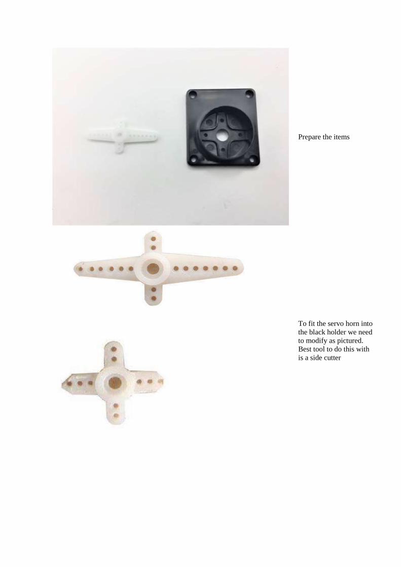
Prepare the items
To fit the servo horn into
the black holder we need
to modify as pictured.
Best tool to do this with
is a side cutter
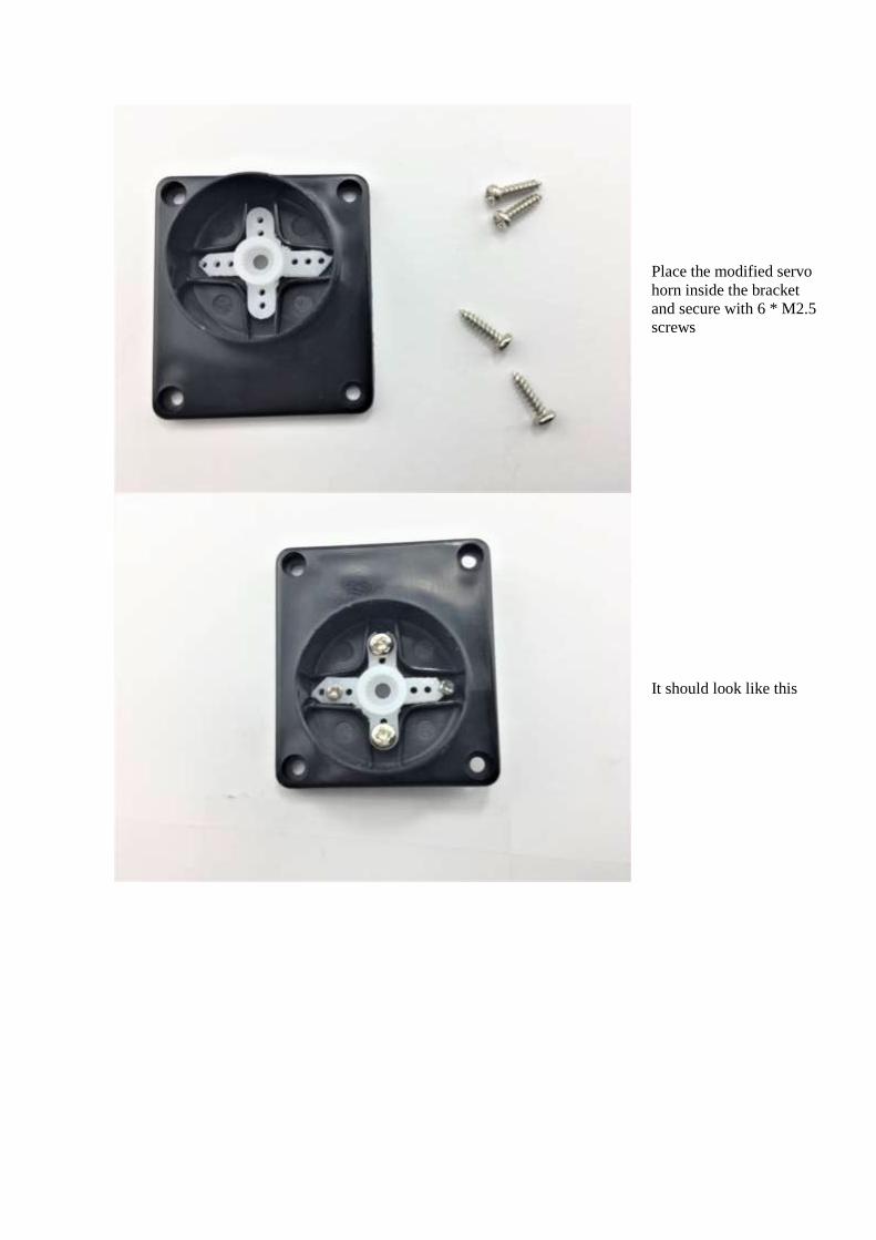
Place the modified servo
horn inside the bracket
and secure with 6 * M2.5
screws
It should look like this
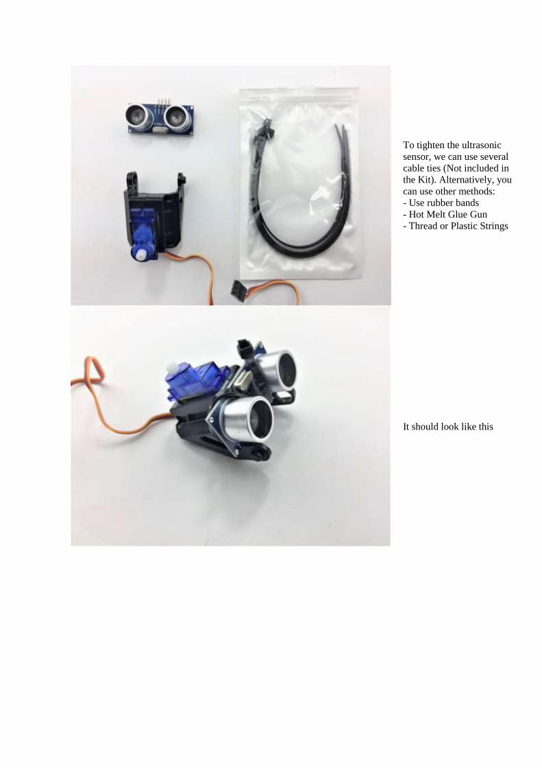
To tighten the ultrasonic
sensor, we can use several
cable ties (Not included in
the Kit). Alternatively, you
can use other methods:
- Use rubber bands
- Hot Melt Glue Gun
- Thread or Plastic Strings
It should look like this
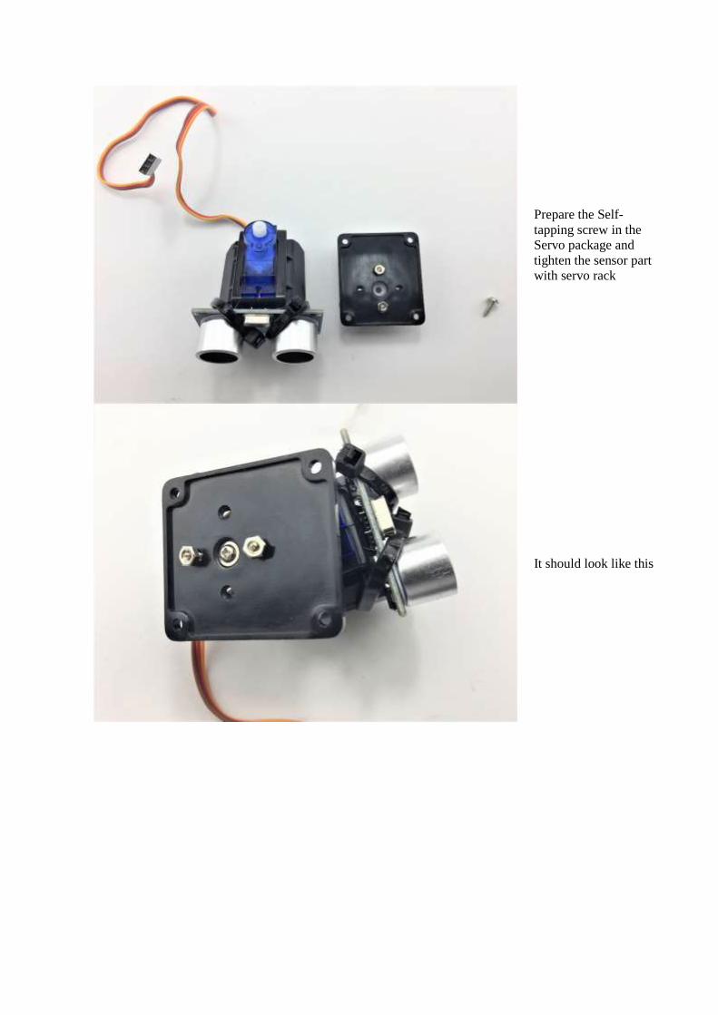
Prepare the Self-
tapping screw in the
Servo package and
tighten the sensor part
with servo rack
It should look like this

Gather four M2.5 screws
and corresponding nuts
in the FPV package to
secure to the bottom
chassis
Finished!
4.5. Switch
The switch can save you a lot energy turning the car on and off. However, it’s just an option. It can be
done by putting the switch in line with the battery box power wire.
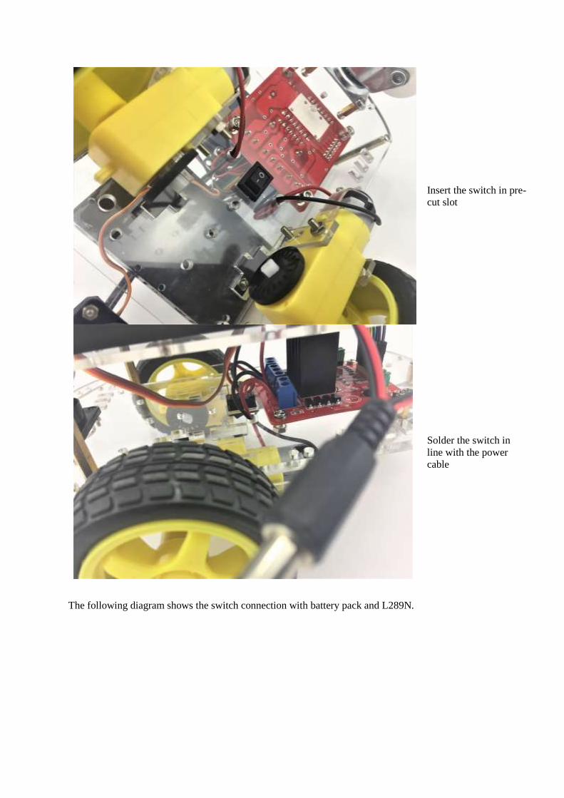
Insert the switch in pre-
cut slot
Solder the switch in
line with the power
cable
The following diagram shows the switch connection with battery pack and L289N.
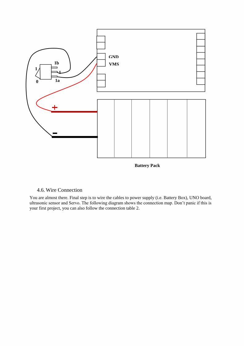
4.6. Wire Connection
You are almost there. Final step is to wire the cables to power supply (i.e. Battery Box), UNO board,
ultrasonic sensor and Servo. The following diagram shows the connection map. Don’t panic if this is
your first project, you can also follow the connection table 2.
L289N 1b
1
1a 0
1
Battery Pack
GND
VMS

Figure 3 Connection map
Figure 4 Arduino Sensor shield v5.0 Diagram

Table 2 Connection table
UNO board Sensor
Shield
L289N Battery
Box
Motor
left
Motor
Right
Servo Ultrasonic
sensor
GND GND
VMS VMS
+(Left) +(red)
-(Left) -(black)
+(Right) +(red)
-(Right) -(black)
V ENA
6 IN1
9 IN2
10 IN3
11 IN4
V ENB
G GND
V 5V+
5 S
V +
G -
V +
A1 Trig
A0 Echo
S -
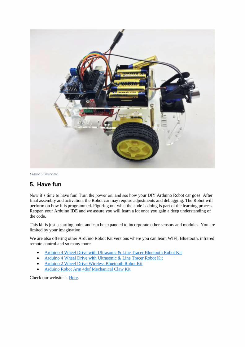
Figure 5 Overview
5. Have fun
Now it’s time to have fun! Turn the power on, and see how your DIY Arduino Robot car goes! After
final assembly and activation, the Robot car may require adjustments and debugging. The Robot will
perform on how it is programmed. Figuring out what the code is doing is part of the learning process.
Reopen your Arduino IDE and we assure you will learn a lot once you gain a deep understanding of
the code.
This kit is just a starting point and can be expanded to incorporate other sensors and modules. You are
limited by your imagination.
We are also offering other Arduino Robot Kit versions where you can learn WIFI, Bluetooth, infrared
remote control and so many more.
• Arduino 4 Wheel Drive with Ultrasonic & Line Tracer Bluetooth Robot Kit
• Arduino 4 Wheel Drive with Ultrasonic & Line Tracer Robot Kit
• Arduino 2 Wheel Drive Wireless Bluetooth Robot Kit
• Arduino Robot Arm 4dof Mechanical Claw Kit
Check our website at Here.
Appendix
Code:
********Code begin******** #include <Servo.h> int pinLB=6; // define pin6 as left back connect with IN1 int pinLF=9; // define pin9 as left forward connect with IN2 int pinRB=10; // define pin10 as right back connect with IN3 int pinRF=11; // define pin11 as right back connect with IN4 int inputPin = A0; // define ultrasonic receive pin (Echo) int outputPin =A1; // define ultrasonic send pin(Trig) int Fspeedd = 0; // forward distance int Rspeedd = 0; // right distance int Lspeedd = 0; // left distance int directionn = 0; // Servo myservo; // new myservo int delay_time = 250; // set stable time int Fgo = 8; int Rgo = 6; int Lgo = 4; int Bgo = 2; // forward // turn right // turn left // back void setup() { Serial.begin(9600); pinMode(pinLB,OUTPUT); pinMode(pinLF,OUTPUT); pinMode(pinRB,OUTPUT); pinMode(pinRF,OUTPUT); pinMode(inputPin, INPUT); pinMode(outputPin, OUTPUT); myservo.attach(5); // define the servo pin(PWM) } void advance(int a) // forward { digitalWrite(pinRB,LOW); digitalWrite(pinRF,HIGH); digitalWrite(pinLB,LOW); digitalWrite(pinLF,HIGH); delay(a * 40); } void turnR(int d) //turn right { digitalWrite(pinRB,LOW); digitalWrite(pinRF,HIGH); digitalWrite(pinLB,HIGH); digitalWrite(pinLF,LOW); delay(d * 50); } void turnL(int e) //turn left { digitalWrite(pinRB,HIGH); digitalWrite(pinRF,LOW);

digitalWrite(pinLB,LOW); digitalWrite(pinLF,HIGH); delay(e * 50); } void stopp(int f) //stop { digitalWrite(pinRB,HIGH); digitalWrite(pinRF,HIGH); digitalWrite(pinLB,HIGH); digitalWrite(pinLF,HIGH); delay(f * 100); } void back(int g) //back { digitalWrite(pinRB,HIGH); digitalWrite(pinRF,LOW); digitalWrite(pinLB,HIGH); digitalWrite(pinLF,LOW); delay(g * 300); } void detection() //test the distance of different direction { int delay_time = 250; // ask_pin_F(); // read forward distance if(Fspeedd < 10) // if distance less then 10 { stopp(1); back(2); } if(Fspeedd < 25) // if distance less then 10 { stopp(1); ask_pin_L(); delay(delay_time); ask_pin_R(); delay(delay_time); if(Lspeedd > Rspeedd) //if left distance more than right distance { directionn = Rgo; } if(Lspeedd <= Rspeedd)//if left distance not more than right //distance { directionn = Lgo; } //if left if (Lspeedd < 10 && Rspeedd < 10) distance and right //distance both less than 10 { directionn = Bgo; } } else { directionn = Fgo; // forward go } }

void ask_pin_F() // test forward distance { myservo.write(90); digitalWrite(outputPin, LOW); delayMicroseconds(2); digitalWrite(outputPin, HIGH); delayMicroseconds(10); digitalWrite(outputPin, LOW); float Fdistance = pulseIn(inputPin, HIGH); Fdistance= Fdistance/5.8/10; Serial.print("F distance:"); Serial.println(Fdistance); Fspeedd = Fdistance; } void ask_pin_L() // test left distance { myservo.write(5); delay(delay_time); digitalWrite(outputPin, LOW); delayMicroseconds(2); digitalWrite(outputPin, HIGH); delayMicroseconds(10); digitalWrite(outputPin, LOW); float Ldistance = pulseIn(inputPin, HIGH); Ldistance= Ldistance/5.8/10; Serial.print("L distance:"); Serial.println(Ldistance); Lspeedd = Ldistance; } void ask_pin_R() // test right distance { myservo.write(177); delay(delay_time); digitalWrite(outputPin, LOW); delayMicroseconds(2); digitalWrite(outputPin, HIGH); delayMicroseconds(10); digitalWrite(outputPin, LOW); float Rdistance = pulseIn(inputPin, HIGH); Rdistance= Rdistance/5.8/10; Serial.print("R distance:"); Serial.println(Rdistance); Rspeedd = Rdistance; } void loop() { myservo.write(90); detection(); if(directionn == 2) { back(8); turnL(2); Serial.print(" Reverse "); } if(directionn == 6) {

back(1); turnR(6); Serial.print(" Right "); } if(directionn == 4) { back(1); turnL(6); Serial.print(" Left ");
} if(directionn == 8) { advance(1); Serial.print(" Advance "); Serial.print(" "); } }
********Code End********