Embed Size (px)
Citation preview
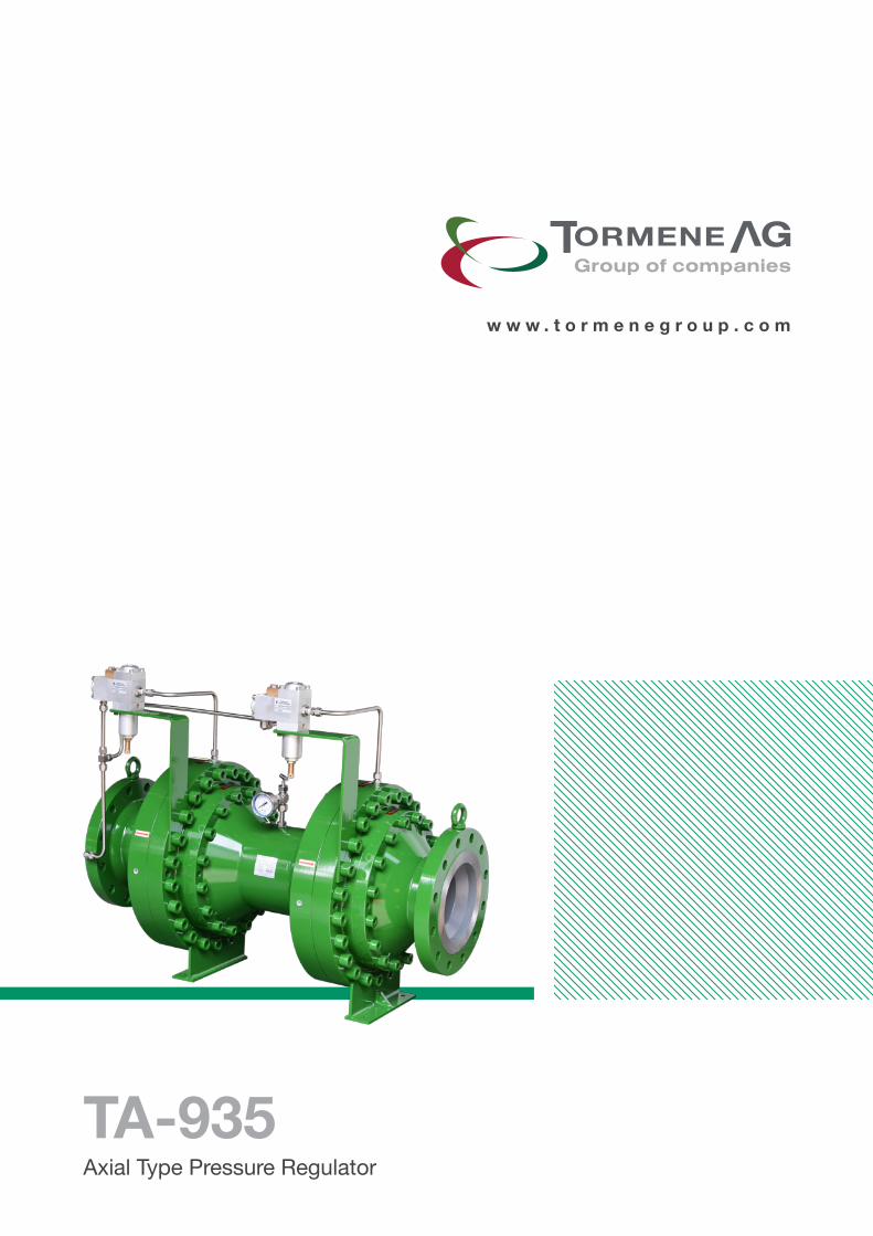
w w w . t o r m e n e g r o u p . c o m
TA-935Axial Type Pressure Regulator
3
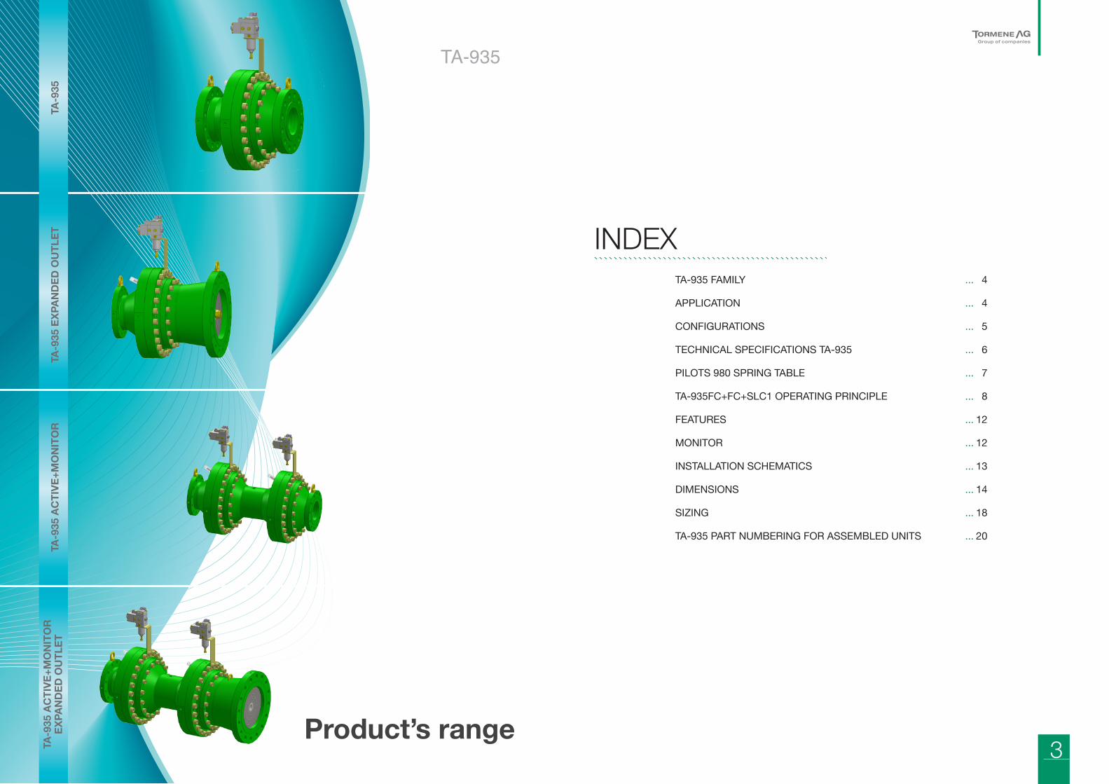
TA-935 FAMILY ... 4
APPLICATION ... 4
CONFIGURATIONS ... 5
TECHNICAL SPECIFICATIONS TA-935 ... 6
PILOTS 980 SPRING TABLE ... 7
TA-935FC+FC+SLC1 OPERATING PRINCIPLE ... 8
FEATURES ... 12
MONITOR ... 12
INSTALLATION SCHEMATICS ... 13
DIMENSIONS ... 14
SIZING ... 18
TA-935 PART NUMBERING FOR ASSEMBLED UNITS ... 20
INDEX
Product’s range
TA-9
35 A
CTI
VE+M
ON
ITO
R
EXPA
ND
ED O
UTL
ETTA
-935
EXP
AND
ED O
UTL
ETTA
-935
AC
TIVE
+MO
NIT
OR
TA-9
35TA-935
4 5
TA-935 | Axial Type Pressure Regulator
TA935 family of axial flow pressure regulators were
designed in order to meet the requirement of several
markets where the advantages and features of axial type
pressure regulators are appreciated.
The design of this range of products was based on our
experience of supplying thousands of TA956 regulators
that are currently in service World-wide.
Most of the critical parts of the New TA935 family are
in common with the successful TA956 family regulators.
TA935 axial flow is providing also the following features:
• High flow rat;
• Balanced valve sleeve;
• Low number of components;
• Modular design;
• Increased outlet flange size;
• Increased silencing options;
• Fail Close & Fail Open designs;
• Integrated 2 in 1 functions FC+FC, FC+FO.
Multi-function units allow exceptionally compact
configurations.
TA-935 FAMILYThe modular design allows a wide variety of configurations
to suit the most demanding applications in gas
transmission, gas supply to industrial power plant, city
gates, distribution utility systems, industry installations,
etc.
TA935 pressure regulators are designed to be used with
non-corrosive and filtered natural gas. Upon request
other gases and different process conditions may be
acceptable with specific choice of materials.
TA935 FC+FC, FC+FO are pilot operated double function
gas pressure regulators. With sleeve piston type regulator
operation (fail open or fail close types) suitable for high,
medium, and low pressure applications.
TA935 pressure regulators are CE marked in accordance
with the following standards:
• EU/97/23/EG A lii B (29.05.1997)
• DIN EN 334 (01 .07.2009)
• DIN EN 14382 (01.07.2009)
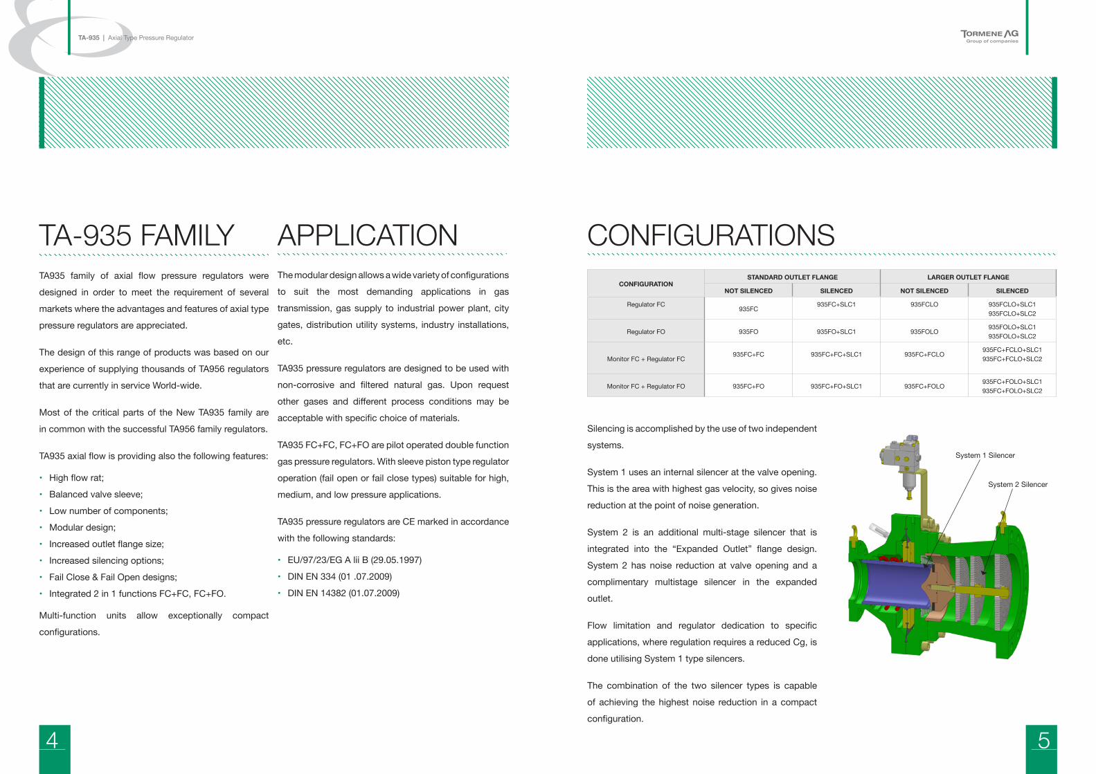
APPLICATIONCONFIGURATION
STANDARD OUTLET FLANGE LARGER OUTLET FLANGE
NOT SILENCED SILENCED NOT SILENCED SILENCED
Regulator FC935FC
935FC+SLC1 935FCLO 935FCLO+SLC1935FCLO+SLC2
Regulator FO 935FO 935FO+SLC1 935FOLO935FOLO+SLC1935FOLO+SLC2
Monitor FC + Regulator FC935FC+FC 935FC+FC+SLC1 935FC+FCLO
935FC+FCLO+SLC1935FC+FCLO+SLC2
Monitor FC + Regulator FO 935FC+FO 935FC+FO+SLC1 935FC+FOLO935FC+FOLO+SLC1935FC+FOLO+SLC2
CONFIGURATIONS
Silencing is accomplished by the use of two independent
systems.
System 1 uses an internal silencer at the valve opening.
This is the area with highest gas velocity, so gives noise
reduction at the point of noise generation.
System 2 is an additional multi-stage silencer that is
integrated into the “Expanded Outlet” flange design.
System 2 has noise reduction at valve opening and a
complimentary multistage silencer in the expanded
outlet.
Flow limitation and regulator dedication to specific
applications, where regulation requires a reduced Cg, is
done utilising System 1 type silencers.
The combination of the two silencer types is capable
of achieving the highest noise reduction in a compact
configuration.
System 1 Silencer
System 2 Silencer
6 7
TA-935 | Axial Type Pressure Regulator
TECHNICAL SPECIFICATIONS TA-935Maximum Inlet Pressure pumax 100 bar (according to flange rating )
Outlet pressure range Wd 0.3 to 74.0 bar
Pressure difference between inlet and outlet
Δpmin= 0.5 bar (FC); Δpmin= 1.85 bar (FO); Δpmax= 100 bar
Nominal diameter and CG value
2” (DN 50) CG=23003” (DN 80) CG=47004” (DN 100) CG=84006” (DN 150) CG=166008” (DN 200) CG=2850010” (DN 250) CG=4600012” (DN 300) CG=66300
Type of connection Flanges ANSI 150, ANSI 300, ANSI 600 (PN 16,25,40,64,100 on request)
Accuracy class and closing pressure category
Up to 1% depending on size and pressure range
With Pilot Outlet pressure range Wd Accuracy class Closing pressure category
TA-989FC 41 … 74 bar AC 1 % SG 5%
TA-981FCHP 20 … 60 bar AC 1 % SG 5%
TA-981FC 0.8 ... 43 bar AC up to 1% SG up to 2.5%
TA-981FCR 0.3 ... 1.2 bar AC 5 % SG 2.5%
TA-988FO 41 ... 74 bar AC 1 % SG 5%
TA-987FOHP 20 ... 60 bar AC 1 % SG 5%
TA-987FO 1 ... 33 bar AC up to 1% SG up to 2.5%
Lock Up pressure category SZ 2.5 %
Operative temperature range -20 °C to +60 °C (-40°C to +60°C available on request)
Operation and strength according to
EN 334, EN 14382, DIRECTIVE 97/23/EC(PED), ANSI B16.5, ANSI B16.34
EX protectionSince the device is not fitted with potential ignition sources of its own, it is not subject to ATEX 95 regulations (all used
electronic accessories meet ATEX requirements).
Accessories Flow limitation, Remote SP control, Station Automation
TA-935 MATERIALSBody ASTM A216 WCB/WCC, ASTM A105 (ASTM A 352LCC/A 350 LF2 ON REQUEST)
Diaphragm housing ASTM A216 WCB/WCC, ASTM A105 (ASTM A 352LCC/A 350 LF2 ON REQUEST)
Valve ASTM A 182 F6/ASTM A105 ENP (ASTM A 350 LF2 ENP on request)
Seat ASTM A105 ENP (ASTM A 350 LF2 ENP on request)
Diaphragm Nitrile rubber with nylon fabric
Seals Nitrile (NBR) or flouroelastomer (FKM)
Pilot Alluminium 6082 T6
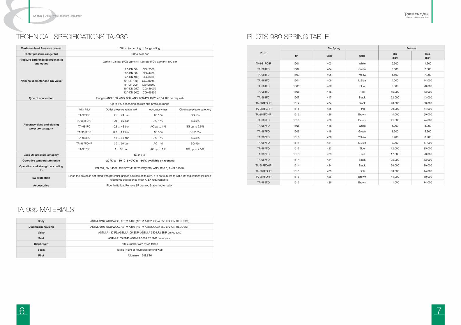
PILOTS 980 SPRING TABLE
PILOT Pilot Spring Pressure
Nr Code ColorMin.[bar]
Max.[bar]
TA-981FC-R 1501 403 White 0.300 1.200
TA-981FC 1502 404 Green 0.800 2.800
TA-981FC 1503 405 Yellow 1.500 7.000
TA-981FC 1504 406 L.Blue 4.000 14.000
TA-981FC 1505 406 Blue 8.000 20.000
TA-981FC 1506 416 Red 15.000 33.000
TA-981FC 1507 417 Black 22.000 43.000
TA-981FCHP 1514 424 Black 20.000 30.000
TA-981FCHP 1515 425 Pink 30.000 44.000
TA-981FCHP 1516 426 Brown 44.000 60.000
TA-989FC 1516 426 Brown 41.000 74.000
TA-987FO 1508 418 White 1.000 3.200
TA-987FO 1509 419 Green 3.200 5.200
TA-987FO 1510 420 Yellow 5.200 8.200
TA-987FO 1511 421 L.Blue 8.200 17.000
TA-987FO 1512 422 Blue 12.000 25.000
TA-987FO 1513 423 Red 17.000 26.000
TA-987FO 1514 424 Black 25.000 33.000
TA-987FOHP 1514 424 Black 20.000 30.000
TA-987FOHP 1515 425 Pink 30.000 44.000
TA-987FOHP 1516 426 Brown 44.000 60.000
TA-988FO 1516 426 Brown 41.000 74.000
8 9
TA-935 | Axial Type Pressure Regulator
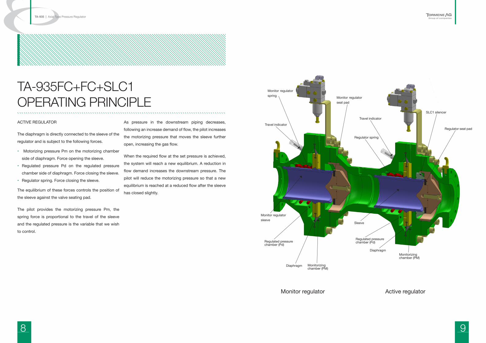
ACTIVE REGULATOR
The diaphragm is directly connected to the sleeve of the
regulator and is subject to the following forces.
• Motorizing pressure Pm on the motorizing chamber
side of diaphragm. Force opening the sleeve.
• Regulated pressure Pd on the regulated pressure
chamber side of diaphragm. Force closing the sleeve.
• Regulator spring. Force closing the sleeve.
The equilibrium of these forces controls the position of
the sleeve against the valve seating pad.
The pilot provides the motorizing pressure Pm, the
spring force is proportional to the travel of the sleeve
and the regulated pressure is the variable that we wish
to control.
As pressure in the downstream piping decreases,
following an increase demand of flow, the pilot increases
the motorizing pressure that moves the sleeve further
open, increasing the gas flow.
When the required flow at the set pressure is achieved,
the system will reach a new equilibrium. A reduction in
flow demand increases the downstream pressure. The
pilot will reduce the motorizing pressure so that a new
equilibrium is reached at a reduced flow after the sleeve
has closed slightly.
TA-935FC+FC+SLC1 OPERATING PRINCIPLE
Travel indicator
Travel indicator
SLC1 silencer
Regulator seat pad
Monitor regulator spring Monitor regulator
seat pad
Regulator spring
Monitor regulator sleeve
Sleeve
Diaphragm
Monitor regulator Active regulator
Diaphragm
Monitorizing chamber (PM)
Monitorizing chamber (PM)
Regulated pressurechamber (Pd)
Regulated pressurechamber (Pd)
10 11
TA-935 | Axial Type Pressure Regulator
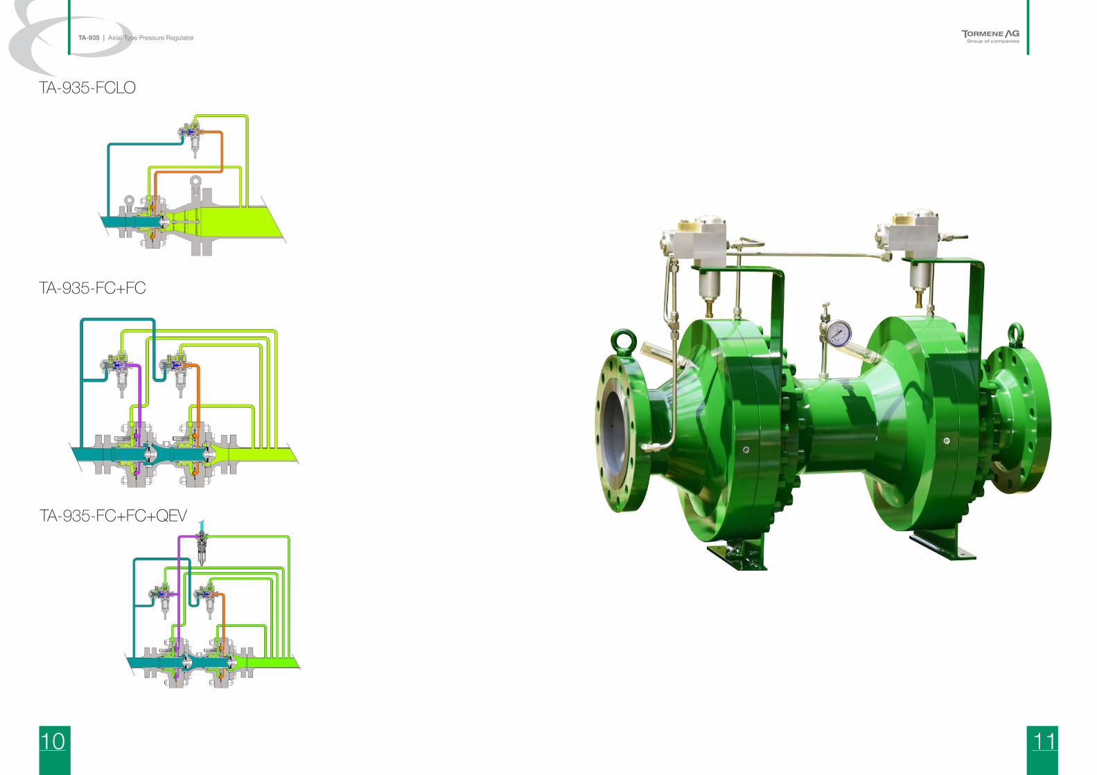
TA-935-FCLO
TA-935-FC+FC+QEV
TA-935-FC+FC
12 13
TA-935 | Axial Type Pressure Regulator
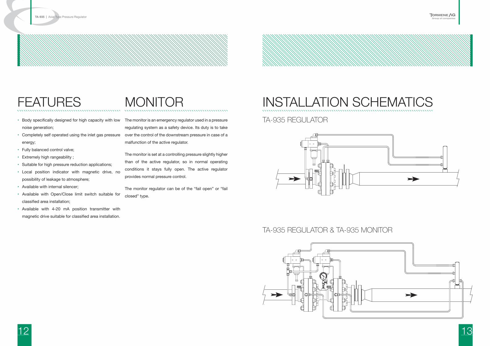
INSTALLATION SCHEMATICSTA-935 REGULATOR
TA-935 REGULATOR & TA-935 MONITOR
• Body specifically designed for high capacity with low
noise generation;
• Completely self operated using the inlet gas pressure
energy;
• Fully balanced control valve;
• Extremely high rangeability ;
• Suitable for high pressure reduction applications;
• Local position indicator with magnetic drive, no
possibility of leakage to atmosphere;
• Available with internal silencer;
• Available with Open/Close limit switch suitable for
classified area installation;
• Available with 4-20 mA position transmitter with
magnetic drive suitable for classified area installation.
FEATURESThe monitor is an emergency regulator used in a pressure
regulating system as a safety device. Its duty is to take
over the control of the downstream pressure in case of a
malfunction of the active regulator.
The monitor is set at a controlling pressure slightly higher
than of the active regulator, so in normal operating
conditions it stays fully open. The active regulator
provides normal pressure control.
The monitor regulator can be of the “fail open” or “fail
closed” type.
MONITOR
14 15
TA-935 | Axial Type Pressure Regulator
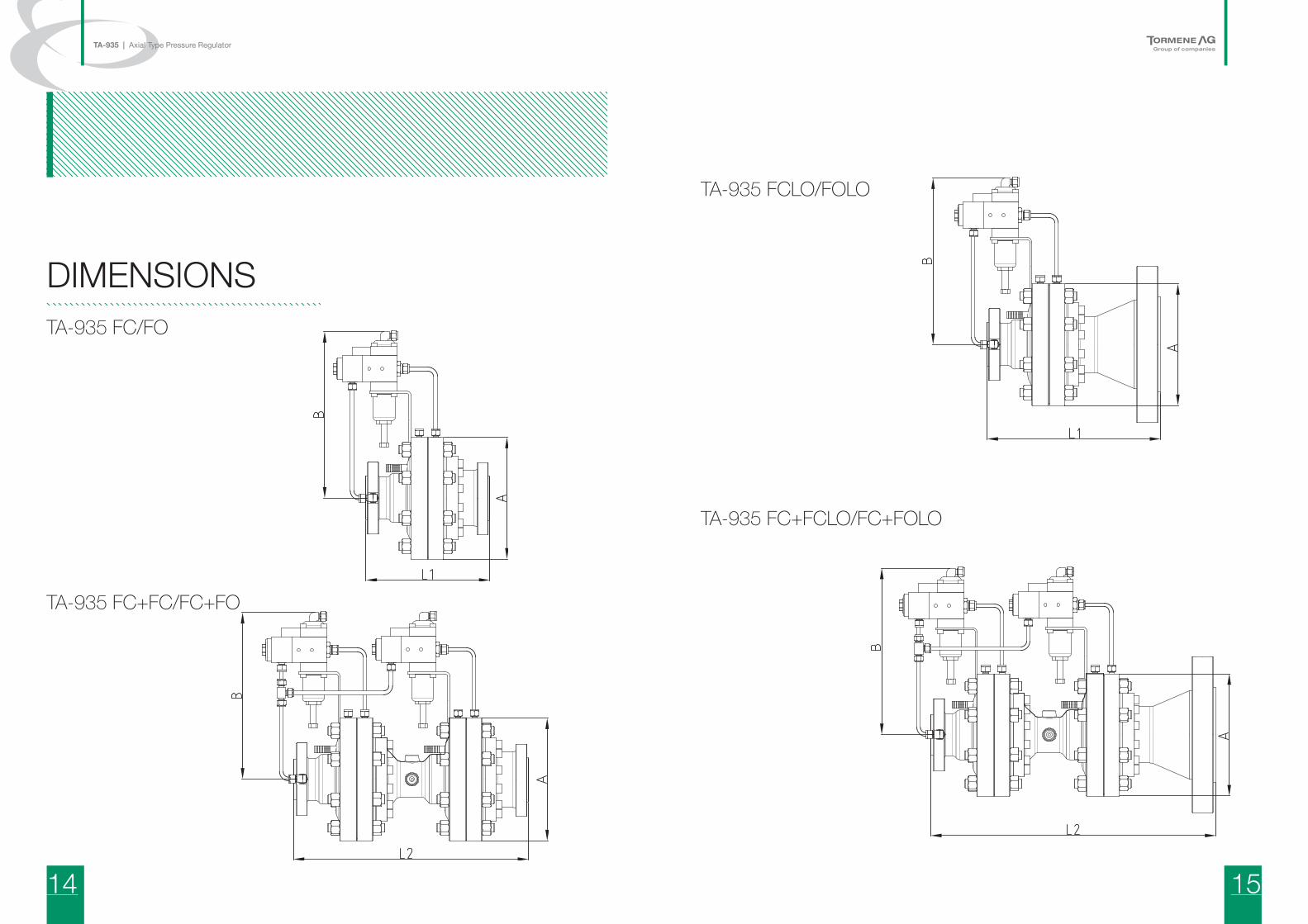
DIMENSIONSTA-935 FC/FO
TA-935 FC+FC/FC+FO
TA-935 FCLO/FOLO
TA-935 FC+FCLO/FC+FOLO
16 17
TA-935 | Axial Type Pressure Regulator
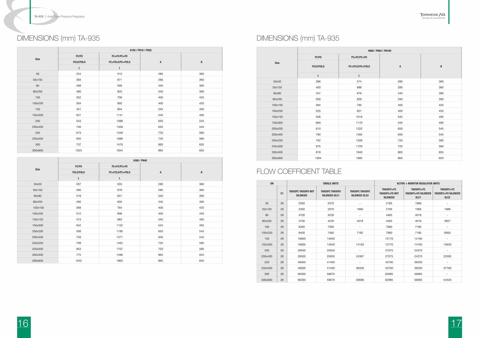
DIMENSIONS (mm) TA-935
Size
#150 / PN16 / PN25
FC/FO FC+FC/FC+FO
A B FCLO/FOLO FC+FCLO/FC+FOLO
L L
50 254 510 280 360
50x150 383 671 280 360
80 298 598 340 390
80x250 480 820 340 390
100 352 706 400 420
100x250 504 900 400 420
150 451 904 545 495
150x300 631 1141 545 495
200 543 1088 650 545
200x400 746 1358 650 545
250 673 1348 720 580
250x500 935 1689 720 580
300 737 1476 865 655
300x600 1023 1844 865 655
Size
#300 / PN40
FC/FO FC+FC/FC+FO
A BFCLO/FOLO FC+FCLO/FC+FOLO
L L
50x50 267 555 280 360
50x150 390 678 280 360
80x80 318 657 340 390
80x250 490 830 340 390
100x100 368 764 400 420
100x250 512 908 400 420
150x150 473 983 545 495
150x300 642 1152 545 495
200x200 568 1180 650 545
200x400 759 1371 650 545
250x250 708 1462 720 580
250x500 953 1707 720 580
300x300 775 1596 865 655
300x600 1042 1863 865 655
DIMENSIONS (mm) TA-935
Size
#600 / PN64 / PN100
FC/FO FC+FC/FC+FO
A BFCLO/FOLO FC+FCLO/FC+FOLO
L L
50x50 286 574 280 360
50x150 400 688 280 360
80x80 337 676 340 390
80x250 500 839 340 390
100x100 394 790 400 420
100x250 525 921 400 420
150x150 508 1018 545 495
150x300 660 1170 545 495
200x200 610 1222 650 545
200x400 780 1392 650 545
250x250 752 1506 720 580
250x500 975 1729 720 580
300x300 819 1640 865 655
300x600 1064 1885 865 655
FLOW COEFFICIENT TABLEDN SINGLE UNITS ACTIVE + MONITOR REGULATOR UNITS
C1TA935FC TA935FO NOT
SILENCEDTA935FC TA935FO SILENCED SLC1
TA935FC TA935FO SILENCED SLC2
TA935FC+FC TA935FC+FO NOT
SILENCED
TA935FC+FC TA935FC+FO SILENCED
SLC1
TA935FC+FC TA935FC+FO SILENCED
SLC2
50 28 2300 2070 ‐ 2185 1966 ‐
50x150 28 2300 2070 1966 2185 1966 1888
80 28 4700 4230 ‐ 4465 4018 ‐
80x250 28 4700 4230 4018 4465 4018 3857
100 28 8400 7560 ‐ 7980 7185 ‐
100x250 28 8400 7560 7182 7980 7185 6900
150 28 16600 14940 ‐ 15770 14195 ‐
150x300 28 16600 14940 14193 15770 14195 13630
200 28 28500 25650 ‐ 27075 24370 ‐
200x400 28 28500 25650 24367 27075 24370 23395
250 28 46000 41400 ‐ 43700 39330 ‐
250x500 28 46000 41400 39330 43700 39330 37760
300 28 66300 59670 ‐ 62985 56685 ‐
300x600 28 66300 59670 56686 62985 56685 54420
18 19
TA-935 | Axial Type Pressure Regulator
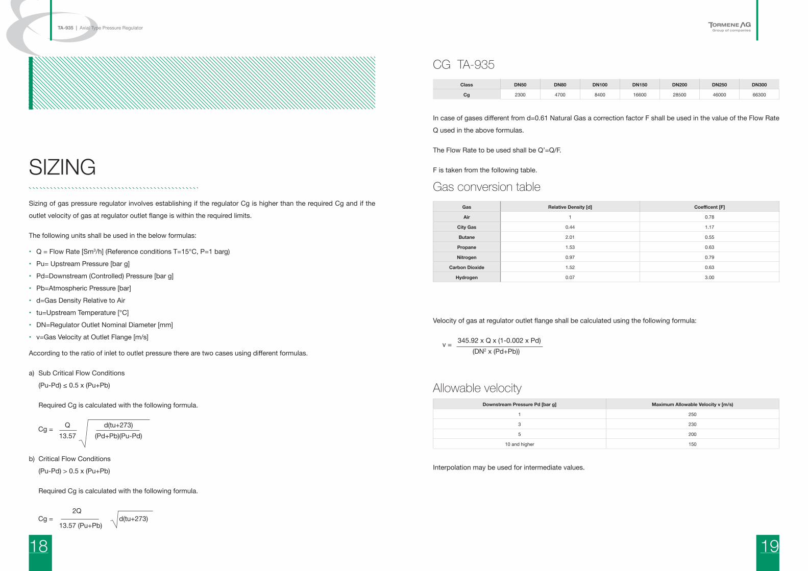
Sizing of gas pressure regulator involves establishing if the regulator Cg is higher than the required Cg and if the
outlet velocity of gas at regulator outlet flange is within the required limits.
The following units shall be used in the below formulas:
• Q = Flow Rate [Sm3/h] (Reference conditions T=15°C, P=1 barg)
• Pu= Upstream Pressure [bar g]
• Pd=Downstream (Controlled) Pressure [bar g]
• Pb=Atmospheric Pressure [bar]
• d=Gas Density Relative to Air
• tu=Upstream Temperature [°C]
• DN=Regulator Outlet Nominal Diameter [mm]
• v=Gas Velocity at Outlet Flange [m/s]
According to the ratio of inlet to outlet pressure there are two cases using different formulas.
a) Sub Critical Flow Conditions
(Pu-Pd) ≤ 0.5 x (Pu+Pb)
Required Cg is calculated with the following formula.
Q d(tu+273) Cg = 13.57 (Pd+Pb)(Pu-Pd)
b) Critical Flow Conditions
(Pu-Pd) > 0.5 x (Pu+Pb)
Required Cg is calculated with the following formula.
2Q Cg = d(tu+273) 13.57 (Pu+Pb)
CG TA-935Class DN50 DN80 DN100 DN150 DN200 DN250 DN300
Cg 2300 4700 8400 16600 28500 46000 66300
In case of gases different from d=0.61 Natural Gas a correction factor F shall be used in the value of the Flow Rate
Q used in the above formulas.
The Flow Rate to be used shall be Q’=Q/F.
F is taken from the following table.
Gas conversion table Gas Relative Density [d] Coefficent [F]
Air 1 0.78
City Gas 0.44 1.17
Butane 2.01 0.55
Propane 1.53 0.63
Nitrogen 0.97 0.79
Carbon Dioxide 1.52 0.63
Hydrogen 0.07 3.00
Velocity of gas at regulator outlet flange shall be calculated using the following formula:
345.92 x Q x (1-0.002 x Pd) v = (DN2 x (Pd+Pb))
Allowable velocity Downstream Pressure Pd [bar g] Maximum Allowable Velocity v [m/s)
1 250
3 230
5 200
10 and higher 150
Interpolation may be used for intermediate values.
SIZING
20 21
TA-935 | Axial Type Pressure Regulator
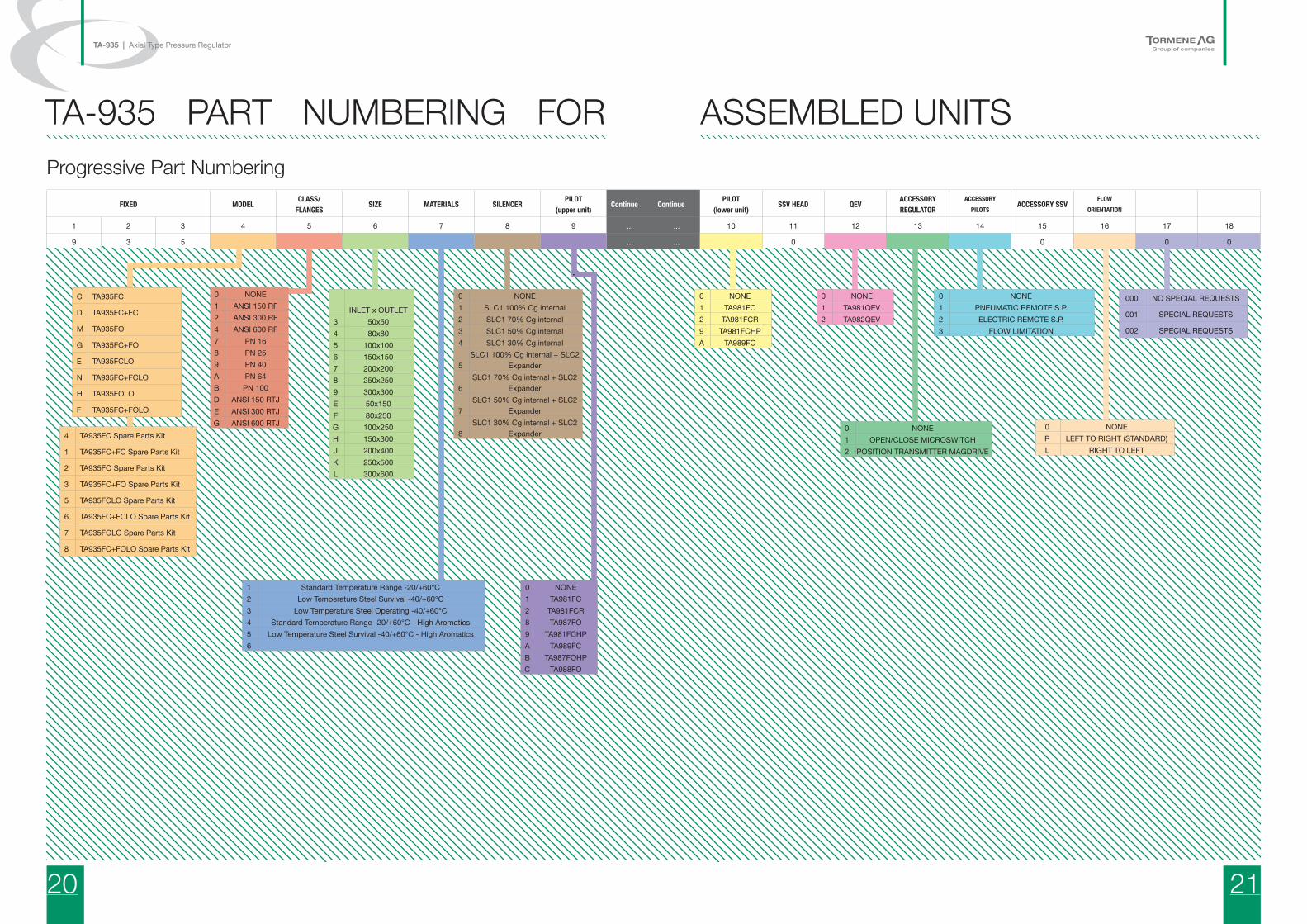
TA-935 PART NUMBERING FOR ASSEMBLED UNITSProgressive Part Numbering
FIXED MODELCLASS/
FLANGESSIZE MATERIALS SILENCER
PILOT(upper unit)
Continue ContinuePILOT
(lower unit)SSV HEAD QEV
ACCESSORYREGULATOR
ACCESSORYPILOTS
ACCESSORY SSVFLOW
ORIENTATION
1 2 3 4 5 6 7 8 9 ... ... 10 11 12 13 14 15 16 17 18
9 3 5 ... ... 0 0 0 0
C TA935FC
D TA935FC+FC
M TA935FO
G TA935FC+FO
E TA935FCLO
N TA935FC+FCLO
H TA935FOLO
F TA935FC+FOLO
4 TA935FC Spare Parts Kit
1 TA935FC+FC Spare Parts Kit
2 TA935FO Spare Parts Kit
3 TA935FC+FO Spare Parts Kit
5 TA935FCLO Spare Parts Kit
6 TA935FC+FCLO Spare Parts Kit
7 TA935FOLO Spare Parts Kit
8 TA935FC+FOLO Spare Parts Kit
000 NO SPECIAL REQUESTS
001 SPECIAL REQUESTS
002 SPECIAL REQUESTS
0 NONE1 ANSI 150 RF2 ANSI 300 RF4 ANSI 600 RF7 PN 168 PN 259 PN 40A PN 64B PN 100D ANSI 150 RTJE ANSI 300 RTJG ANSI 600 RTJ
INLET x OUTLET3 50x504 80x805 100x1006 150x1507 200x2008 250x2509 300x300E 50x150F 80x250G 100x250H 150x300J 200x400K 250x500L 300x600
1 Standard Temperature Range -20/+60°C2 Low Temperature Steel Survival -40/+60°C3 Low Temperature Steel Operating -40/+60°C4 Standard Temperature Range -20/+60°C - High Aromatics5 Low Temperature Steel Survival -40/+60°C - High Aromatics6
0 NONE1 SLC1 100% Cg internal2 SLC1 70% Cg internal3 SLC1 50% Cg internal4 SLC1 30% Cg internal
5SLC1 100% Cg internal + SLC2
Expander
6SLC1 70% Cg internal + SLC2
Expander
7SLC1 50% Cg internal + SLC2
Expander
8SLC1 30% Cg internal + SLC2
Expander
0 NONE1 TA981FC2 TA981FCR8 TA987FO9 TA981FCHPA TA989FCB TA987FOHPC TA988FO
0 NONE1 TA981FC2 TA981FCR9 TA981FCHPA TA989FC
0 NONE1 TA981QEV2 TA982QEV
0 NONE1 OPEN/CLOSE MICROSWITCH2 POSITION TRANSMITTER MAGDRIVE
0 NONE1 PNEUMATIC REMOTE S.P.2 ELECTRIC REMOTE S.P.3 FLOW LIMITATION
0 NONER LEFT TO RIGHT (STANDARD)L RIGHT TO LEFT

22 23
TA-935 | Axial Type Pressure Regulator
Tormene AmericanaBuenos Aires - Argentina - +54 4897.5999
Tormene Americana BrasilRio de Janeiro - Brazil - +55 21 2510.6155
Tormene AndinaLima - Peru - +511 628.1595/[email protected]
www.tormeneandina.com.pe
Euromag InternationalPadua - Italy - +39 049 9005064
TA Valves & Regulators +86 813 321.6535
Tormene IndustrialePadua - Italy - +39 049 9004107
Tormene NigeriaNigeria - +234(0)7088085024
Tormene AmericanaColombia - +5411 4524.5777
Tormene AGWalzenhausen - Switzerland - 0041/(0)71/588.03.15
GES Gas-Energy-Solutions GmbHGermany +49 (0) 561 99856660
Tormene AG RUSRussia +7-3513-255-064
Prog
etto
: 15
-TA93
5-EN
G-R
00
All rights reserved. No part of this catalogue may be reproduced, stored in a database or otherwise used without the authorisation of Tormene. The policy of Tormene is dictated by the continuing technological and project innovation. Therefore, the Company reserves the right to amend the data contained herein without notice.


![TA-935...2019/05/15 · Seals Nitrile (NBR) or flouroelastomer (FKM) Pilot Alluminium 6082 T6 7 PILOTS 980 SPRING TABLE PILOT Pilot Spring Pressure Nr Code Color Min. [bar] Max. [bar]](https://img.pdfslide.us/doc/110x75/60907040a777e83b072938b6/ta-935-20190515-seals-nitrile-nbr-or-flouroelastomer-fkm-pilot-alluminium.jpg)