Embed Size (px)
Citation preview

TA
SM
AN
IAN
QU
AL
IFIC
AT
ION
S A
UT
HO
RIT
Y
T A S M A N I A N Advanced Electronics
C E R T I F I C A T E Subject Code: ELT315109 O F E D U C A T I O N 2012 Assessment Report
2012 Assessment Report
Written Examination Paper A significant number of candidates did not do well in any of the three sections of the examination. All candidates attempted all three sections of the examination. Section A – Criterion 2 Question 1 a) Most candidates correctly drew series and parallel capacitor pairs but many did not
convert the capacitor values to nanofarads. b) Many candidates used the correct method of finding the total capacitance but not
always obtaining the correct answer. Question 2 A minority of candidates showed an understanding of the two op-amp applications. Those who did well recognised the mode of operation of the op-amp from the connections made from input to output and input to 0V. Question 3 a) All candidates who correctly answered this question drew an RC filter. An RL filter
would have been accepted. b) Many candidates correctly calculated the required capacitor value. Question 4 Very few candidates understood the inductive properties of the relay coil and the damage that can be done by high voltage inductive spikes when the current to the relay is cut off. Too many candidates thought the transistor is at risk of damage from the 240V that the relay is switching or because there is no resistor in the collector circuit. Those who correctly recognised the problem understood the solution. Question 5 Parts (a) and (b) (i) were well answered but part (b) (ii) was not correctly answered by many. Part (c) required a good memory for detail but was answered well by many candidates.

Advanced Electronics 2
Subject Code: ELT315109
2012 Assessment Report
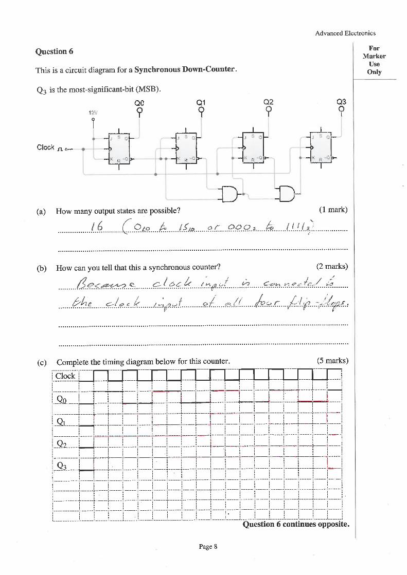
Question 6 Part (a) was poorly answered by all but a few candidates. It seemed that the two AND gates were taken to be there to reduce the modulus of the counter. However, most candidates recognised the characteristics that make it a synchronous counter. Few candidates obtained full marks for the timing diagram. Question 7 Many candidates had trouble predicting the output of this reasonably simple logic circuit. Some did not make use of the intermediate logic states for which provision was made in the truth table. Many candidates’ table in part (c) did not match their truth table. Section B – Criterion 8 Question 8 Many candidates showed some understanding of the benefits of an op-amp’s low output impedance. Question 9 Most candidates correctly answered part a of this question but few candidates understood capacitor time constants well enough to correctly completed the graph in part (b). Question 10 Many candidates understood voltage dividers well enough to complete at least part of this question. The function of a resistive bridge was understood by many. Question 11 This was poorly answered by many candidates. The role of the diodes in clipping the input signal and limiting its voltage to ~0.7V was generally not understood. Those who understood the role of the diodes often did not realise that the gain of the amplifier is unity for signals under 0.7Vp but the gain is -2 for signals over 0.7Vp. When the diodes conduct R3 is no longer part of the gain controlling voltage divider.

Advanced Electronics 3
Subject Code: ELT315109
2012 Assessment Report
Question 12 This was well answered by many candidates. Despite much information being given in the question candidates did not always answer part (c) and (d) well. Part (e), (ii) regarding the switch on reset function caused candidates the most trouble. Question 13 This was quite well answered but some candidates placed the logic gate before the comparators. Section C – Criterion 9 Question 14 Part (a) was well answered but many candidates did not use 714 ohms (680 + 5% ohms) in the calculation of the minimum current when answering part (b). Question 15 Finding the input voltage to a voltage divider when the output voltage is given was too difficult for most candidates. This is understandable as the formula is not on the Information Sheet supplied to candidates and most did not have the mathematical skills to transpose the formula given. Many candidates did not interpret the circuit correctly when applying the formula from the Information Sheet. Resistors R1 and R2 on the circuit diagram were substituted directly into the formula by many candidates and so R1 was replaced with R2 and R2 was replaced with R1. Question 16 This question was well answered by many candidates. Question 17 This was a demanding question that was poorly answered by many candidates.
Advanced Electronics 4
Subject Code: ELT315109
2012 Assessment Report
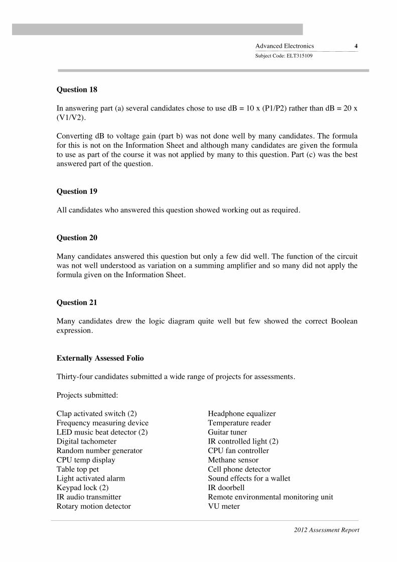
Question 18 In answering part (a) several candidates chose to use dB = 10 x (P1/P2) rather than dB = 20 x (V1/V2). Converting dB to voltage gain (part b) was not done well by many candidates. The formula for this is not on the Information Sheet and although many candidates are given the formula to use as part of the course it was not applied by many to this question. Part (c) was the best answered part of the question. Question 19 All candidates who answered this question showed working out as required. Question 20 Many candidates answered this question but only a few did well. The function of the circuit was not well understood as variation on a summing amplifier and so many did not apply the formula given on the Information Sheet. Question 21 Many candidates drew the logic diagram quite well but few showed the correct Boolean expression. Externally Assessed Folio Thirty-four candidates submitted a wide range of projects for assessments. Projects submitted: Clap activated switch (2) Headphone equalizer Frequency measuring device Temperature reader LED music beat detector (2) Guitar tuner Digital tachometer IR controlled light (2) Random number generator CPU fan controller CPU temp display Methane sensor Table top pet Cell phone detector Light activated alarm Sound effects for a wallet Keypad lock (2) IR doorbell IR audio transmitter Remote environmental monitoring unit Rotary motion detector VU meter

Advanced Electronics 5
Subject Code: ELT315109
2012 Assessment Report
Helmet camera roll-off motor IR trip wire Motion detector Drought sensor LED door bell Headphone amplifier IR controlled model car Audio equaliser The markers were impressed by the high standard of design and construction shown in some of the projects although many projects were not finished. Too many candidates chose projects that were evidently too demanding. The markers felt that if simpler projects had been chosen the candidates would have been more likely to have them working and well presented for assessment. Where possible candidates should mount their projects in an enclosure with labelling to indicate the project’s name, inputs, outputs and controls. If an enclosure is not appropriate a project may be mounted on a piece of board or plastic sheet. Some projects were roughly mounted onto a piece of unprepared scrap MDF or plywood with inadequate labelling. Almost all candidates used a CAD application such as Circuit Wizard to design printed circuit boards (PCBs). This is expected of candidates. The majority of projects employed photographic transfer of PCB pattern to copper clad board greatly enhancing the appearance of the finished project. Circuit boards were generally well finished being cleaned to remove soldering flux before being coated with PCB lacquer. All projects used a complexity of circuit design that is commensurate with the Advanced Electronics course. Only one project using a double sided PCB. Projects need not be so complex as to need a double sided PCB. A few candidates did not ‘manually’ finish the computer generated PCB design. This finishing often involves reducing the PCB size to avoid wasting PCB area and modifying routing to neaten wire links and reduce track length. Wire links on the PCB should run on the X and Y axes of the board. PCB wire links should be made from bare tinned wire (off-cuts from components are often ideal) and should be placed flat on the component side of the PCB. Wiring should be long enough to allow inspection of both sides of the PCB without risk of breaking a wiring connection. Multiple wires should be colour coded and secured in harnesses using cable ties or the more traditional method of tying with thin cord. The checklist for assessment of criterion 3 in the Examination Guidelines, should be referred to during the design and construction of projects.

Advanced Electronics 6
Subject Code: ELT315109
2012 Assessment Report
Project Reports Criterion 4 and Criterion 6 were used to assess the written reports on the projects. Criterion 4 Most reports were well presented and all were produced using a word processor application. Although many candidates followed the required report format set out in the Examination Guidelines several showed no evidence that the guidelines had been considered. Candidates that followed the guidelines and addressed each of the points on the checklists were generally very successful. It is expected that the written report on the project show stages in project development; • The project should evolve from a clearly stated problem that the project is intended to
solve. The problem should be detailed in the Rational section of the report.
For example, for a project that is intended control a fan that is needed to keep a computer cool, an explanation of why computers need to be kept cool and the problems that arise if they overheat should be discussed. Then the project can be suggested as a solution to the problem of maintaining a safe operating temperature within a computer.
• Using the problem as a starting point, candidates should research a wide range of topics
related to the problem to be solved and examine possible electronic solutions. This should be documented in the Research section of the report.
Continuing the above example; research could be done to elaborate the issue of high temperatures in computers and detail solutions to this problem that have been used, (heatsinking, fans, temperature controlled fans).
• Based on the research done a solution to the problem is chosen and justified. The
design construction and testing of appropriate circuits is then carried out and described in the Design section of the report. The choice of circuits used should be justified.
• Once construction is complete an evaluation of the project should be carried out and
written up in the Evaluation section of the report. Not all reports showed the stages of development that the project went through. Schematic circuit and function block diagrams were generally well presented but were missing in a few reports. These diagrams are fundamental to communicating understanding of an electronic circuit. A candidate submitting a report lacking in schematic circuit diagrams and block diagrams appropriately located in the report reflects a lack of conceptual development in the subject. Similarly PCB design was not always well described and the PCB components placement layout and artwork were not always presented in the report.

Advanced Electronics 7
Subject Code: ELT315109
2012 Assessment Report
Many candidates wrote their reports in the first person, e.g. ‘I constructed this project’. It is preferred that the reports be written in the third person with the design, construction and evaluation of the project being the subject of sentences rather than having the candidate as the subject. e.g. ‘This project was built’. Most candidates prepared an Operator’s Manual to accompany their project. The better manuals were set out as a separate four page brochure as might be included with a simple consumer item. The markers like to refer to the operator’s manual to find a concise explanation of the project’s function and what is required to use it. Criterion 6 This criterion was assessed using the written report and logbook. Evidence for assessing this criterion includes the consideration of the problem the project is intended to solve, the problems solved in the design, construction, testing and evaluation of the project. Candidates should be sure to research various solutions to the problem they are to solve. Alternatives should be considered and the reasons for choosing one over the others described. This is in addition to general research into the problem to be solved and the electronic technologies that might be part of the solution. Many candidates could have included a more thorough explanation of the mathematics, digital logic, Boolean algebra and programming involved in the design and operation of the project. Many reports needed to have a more detailed evaluation of the project. Testing procedures should be detailed and results from testing should be discussed. Again the Examination Guidelines detail what is required. Log Books The logbook supported the assessment of Criterion 6. Most logbooks showed the work completed on the project during each classroom session and the work planned for the next session or week. Enhancement of logbooks by the inclusion of diagrams of circuits being tested, test results and conclusions is strongly encouraged. Log books had been signed regularly by teachers.


TASMANIAN QUALIFICATIONS AUTHORITY
ELI3 15109 Advanced Electronics
ASSESSMENT PANEL REPORT
Award Distribution
Student Distribution (SA or better)
EA HA CA SA Total
This year 8%o (2) 29o/o (7) 33% (8) 29o/o (7) 24
Last year 18o/o @) 14Yo (3) 18o/o (4) 50% (11) 22
Last year (allexaminedsubjects)
11% 19 o/o 39 o/o 30 o/o
Previous 5 years 17 o/o 17 o/o 2O o/o 46 o/o
Previous 5 years(all examinedsubjects)
11 o/o 19 o/o 40 o/o 30 o/o
Male Female Year 1L Year L2
This year 1OO% (24) 0% (0) 42% (10) 58To (14)
Last year 1o0o/o (22) o% (0) 32o/o (7) 68% (15)
Previous 5 years 93o/o 7o/o 27o/o 73o/o