Embed Size (px)
Citation preview

T30 Ins ta l la t ion Too l
Hydro-Electric Power Tool
I ns t ruc t i on Manua l

3
Contents
Safety 4
SpecificationsIntent of Use 5Tool Specification 5Tool Dimensions 5
Putting into ServicePrinciple of Operation 6Preparation for Use 6Hydraulic Hose Kits 6Operating Instructions 7
MaintenanceDismantling Instructions 8Assembling the Tool 8To Bleed the Tool 9
General Assembly of T30 Installation Tool73412-02000 10
Parts List for T30 Installation Tool73412-02000 11
Avdel UK Limited policy is one of continuous product development and improvement and we reserve the right to change the specification of any product without prior notice.
WarrantyThe ninety day warranty herein expressed shall be the exclusive warranty on itemsmanufactured by seller and shall be in the place and stead of any other warranty, expressed orimplied, including but not limited to the implied warranties of merchantability and fitness for aparticular purpose.Seller shall not be liable for any loss or damage resulting from delays or non-fulfilment ororders owing to strikes, fires, accidents, transportation companies or for any reason orreasons beyond the control of seller or its suppliers.All warranty claims must be submitted to the seller in writing, within 90 days from date ofshipment, and no returns will be accepted without written permission.Other provisions hereof notwithstanding, seller shall not be liable for any loss of businessprofits or any incidental or consequential damages incurred by Buyer or any third person inconnection with the items or use thereof, however caused.
Tool WarrantySeller expressly disclaims any warranty express or implied, as to the condition, design,operation, merchantability or fitness for use of any tool, or part(s) thereof not manufactured byseller. The only warranties made with respect to such tool or part(s) thereof are those madeby the manufacturer thereof and seller agrees to cooperate with buyer in enforcing suchwarranties when such action is necessary. Seller agrees to repair or replace F.O.B. seller'splant, any tool or part(s) thereof manufactured by it and proved to seller to be defective due tofaulty workmanship or material.
Servicing the ToolDaily / Weekly 12Every 1,200 Working Hours (at least once a year) 12Service Tools 12Hydraulic Oil General Safety Data 12
Fault DiagnosisSymptom, Possible Cause & Remedy 13-14
4
Sa fe ty
1 Do not use outside the design intent.
2 Do not use equipment with this tool/machine other than that recommended by Avdel UK Limited.
3 Any modification undertaken by the customer to the tool/machine shall be the customer’s entire responsibility.
4 Always disconnect the tool from the HydraPac before attempting to adjust, remove or fit the nose assembly.
5 Do not operate a tool/machine that is directed towards any person(s).
6 Always adopt a firm footing or a stable position before operating the tool/machine.
7 If cycling the tool without the nose assembly, care must be taken to avoid contact with the pintail ejector pin and to not trap the
fingers in between the anvil retainer (T304) and the collet adaptor (T307).
8 Ear protection must be worn by the operator and others in the vicinity as noise levels exceed the permitted maximum. For values
see technical specifications on page 5.
9 Do not fit flexible hoses rated at less than 10,000 psi (69 mPa) working pressure.
10 The operating pressure shall not exceed 8,000 psi (55.2 mPa).
11 Care shall be taken to ensure that spent pintails are not allowed to create a hazard.
12 When using the tool, the operator and others in the vicinity are recommended to wear safety glasses.
13 Take care to avoid entanglement of loose clothes, ties, long hair, cleaning rags etc. in the moving parts of the tool.
14 The tool should be kept clean and dry for the best possible grip.
15 When carrying the tool from place to place keep hands away from the trigger to avoid inadvertent start up.
16 The machine must be maintained in a safe working condition at all times and examined at regular intervals for damage and function
by trained competent personnel. Any dismantling procedure shall be undertaken only by personnel trained in Avdel® procedures.
Do not dismantle the machine without prior reference to the maintenance instructions. Contact Avdel® with your training
requirements.
17 The machine shall at all times be operated in accordance with relevant Health & Safety legislation. In the UK the "Health & Safety at
Work etc Act 1974" applies. Any question regarding the correct operation of the machine must be directed to Avdel®.
This instruction manual must be read with particular attention to the following safety rules, by any personinstalling, operating, or servicing this tool.
CAUTIONS
AVDEL RECOMMENDS THAT ONLY HYDRAPAC UNITS BE USED TO DRIVE INSTALLATION TOOLS, AS OTHER MAKES OFHYDRAULIC POWER UNITS MAY NOT OPERATE AT THE SAFE DESIGNED WORKING PRESSURES.
ENSURE THAT THERE IS ADEQUATE CLEARANCE FOR THE TOOL OPERATOR'S HANDS BEFORE PROCEEDING.
DO NOT ABUSE THE TOOL BY DROPPING OR USING IT AS A HAMMER.
KEEP DIRT AND FOREIGN MATTER OUT OF THE HYDRAULIC SYSTEMS OF THE TOOLS AS THIS WILL CAUSE THE TOOL ANDHYDRAPAC TO MALFUNCTION
5
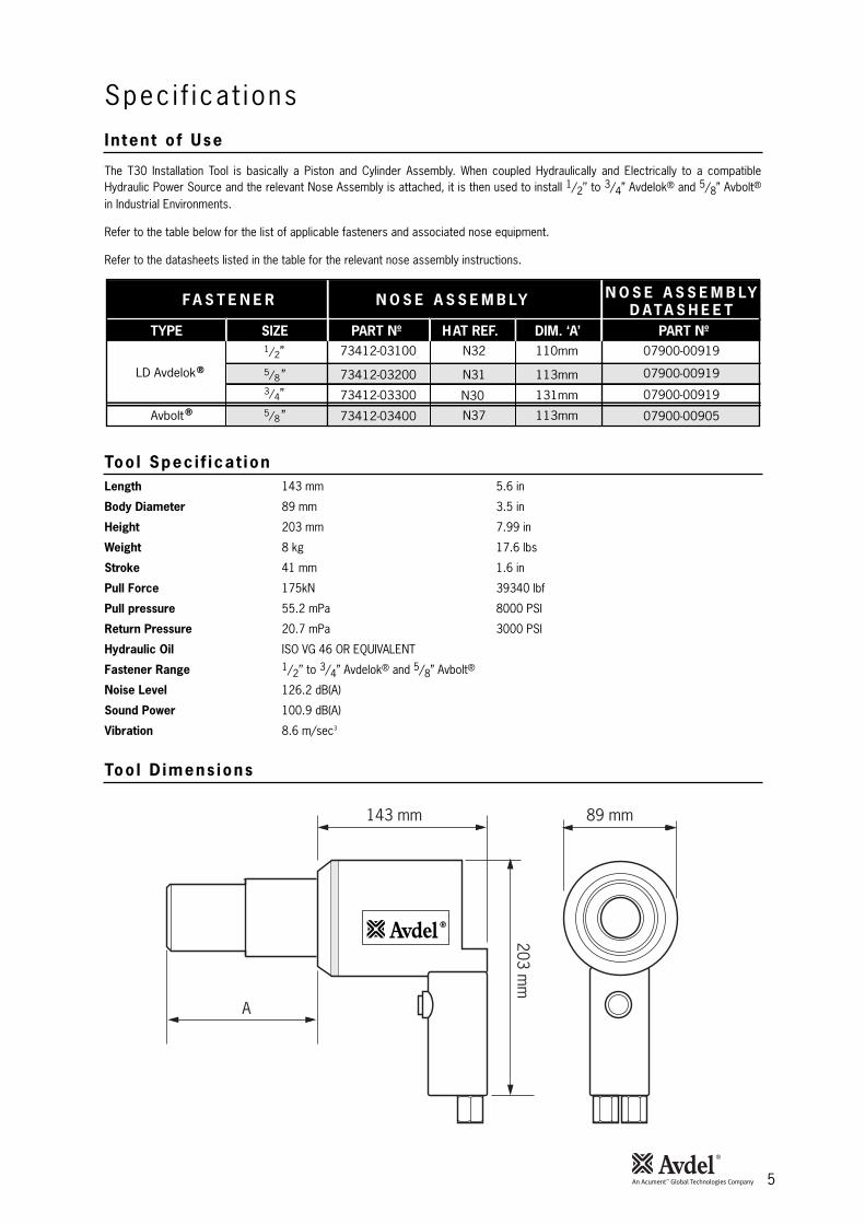
In tent o f Use
Too l Spec i f icat ion
Too l D imens ions
Spec i f ica t ions
The T30 Installation Tool is basically a Piston and Cylinder Assembly. When coupled Hydraulically and Electrically to a compatibleHydraulic Power Source and the relevant Nose Assembly is attached, it is then used to install 1/2’’ to 3/4” Avdelok® and 5/8” Avbolt®
in Industrial Environments.
Refer to the table below for the list of applicable fasteners and associated nose equipment.
Refer to the datasheets listed in the table for the relevant nose assembly instructions.
FA S T E N E R
TYPE SIZE
N O S E A S S E M B LY
PART Nº HAT REF. DIM. ‘A’
N O S E A S S E M B LYD ATA S H E E T
PART Nº
®
07900-00919
07900-00919
07900-00919
07900-00905
73412-03100
73412-03200
73412-03300
73412-03400
N31
N37
N30
Avbolt
LD Avdelok
1/2”
3/4”
5/8”
5/8”
110mm
113mm
131mm
113mm
N32
®
Length 143 mm 5.6 in
Body Diameter 89 mm 3.5 in
Height 203 mm 7.99 in
Weight 8 kg 17.6 lbs
Stroke 41 mm 1.6 in
Pull Force 175kN 39340 lbf
Pull pressure 55.2 mPa 8000 PSI
Return Pressure 20.7 mPa 3000 PSI
Hydraulic Oil ISO VG 46 OR EQUIVALENT
Fastener Range 1/2’’ to 3/4” Avdelok® and 5/8” Avbolt®
Noise Level 126.2 dB(A)
Sound Power 100.9 dB(A)
Vibration 8.6 m/sec3
A
143 mm 89 mm
203 mm
6
Put t i ng In to Serv ice
When both hoses and control cord are connected to the HydraPac, the pull and return cycles of the tool are controlled by depressingand releasing the trigger switch located in the handle respectively.
When the switch is depressed the solenoid valve located in the HydraPac is energised and directs the pressurised oil flow to the pullside of the piston in the tool. This also allows the oil in the return side of the tool to return to the tank. The piston/collet assembly nowmoves towards the rear of the tool allowing the cushion to push the follower and jaws forward. If a Avdelok® pin has been inserted inthe nose for assembly, the jaw set will clamp onto the pintail and assembly will commence.
The cycle of installation will first clamp the joint to be fastened and then as the anvil continues to move forward the collar will beswaged into the locking grooves of the pin. At the end of the swaging cycle the anvil will come hard up against the joint and asmovement continues the pintail will be broken off.
The trigger switch must be released immediately after pin break occurs. Releasing the trigger switch will cause the solenoid to de-energise and reverse the flow of pressurised oil.
Pressurised oil will now flow into the return side of the installation tool with the oil in the pull side returning to the tank.
The forward movement of the piston/collet assembly firstly ejects the installed fastener from the anvil and as the forward movementcontinues, the jaw release mechanism will cause the jaws to open and release the broken off pintail, which will then be ejected.
When the piston returns to the fully forward position the pressure build up in the system will cause the HydraPac to go into idle mode.This keeps the installation tool in the forward position. Once the pintail has been ejected from the nose, the tool is ready for the nextinstallation.
Please note that with all electric HydraPacs there is a built in "Sleep Mode" which in effect means that the electric motor willautomatically switch off if the trigger switch is not operated for approximately 25 seconds. The HydraPac will automatically start up ondepression of the tool trigger switch. (The diesel HydraPac does not have a "Sleep Mode".)
• Attach the correct nose assembly to the tool as per instructions in the relevant nose assembly data sheet.
• Ensure the HydraPac is not running.
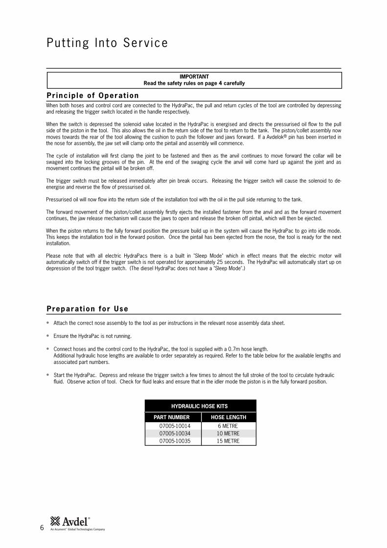
• Connect hoses and the control cord to the HydraPac, the tool is supplied with a 0.7m hose length.Additional hydraulic hose lengths are available to order separately as required. Refer to the table below for the available lengths andassociated part numbers.
• Start the HydraPac. Depress and release the trigger switch a few times to almost the full stroke of the tool to circulate hydraulicfluid. Observe action of tool. Check for fluid leaks and ensure that in the idler mode the piston is in the fully forward position.
IMPORTANTRead the safety rules on page 4 carefully
Pr inc ip le o f Operat ion
Preparat ion for Use
PART NUMBER HOSE LENGTH
HYDRAULIC HOSE KITS
07005-1001407005-1003407005-10035
6 METRE10 METRE15 METRE
7
Put t i ng In to Serv ice
To install a Avdelok® Fastener
• Check work and remove excessive gap. (Gap is the space between components of the Joint. Gap is excessive if not enough pintailsticks through the collar for the nose assembly jaws to grab onto.)
• Put Avdelok® pin into hole.
• Slide Avdelok® collar over pin. (The bevelled end of the collar must be towards the nose assembly and tool.)
• Push nose assembly onto pin until the nose assembly anvil stops against the collar. Tool and nose assembly must be held at rightangles (90°) to the work.
• Depress tool trigger switch to start installation cycle.
• When the forward motion of the nose assembly anvil stops and the pintail breaks off, release the switch. The tool will go into its returnstroke and push off the installed fastener. At the end of the return stroke the jaws will release the expended pintail which can beremoved by tilting the tool down.
• Once the expended pintail has been ejected, the tool and nose assembly is ready for the next installation cycle.
CAUTION
DO NOT ATTEMPT TO BREAK OFF A PINTAIL WITHOUT THE INSTALLATION OF A COLLAR AS THIS WILL CAUSE THEUNSECURED PORTION OF THE AVDELOK® PIN TO EJECT FROM THE NOSE AT A HIGH SPEED AND FORCE.
Operat ing Ins t ruct ions
8
• Uncouple the two hydraulic hoses and disconnect the control cord.
• Unscrew and remove the anvil by hand.
• Unscrew the collet and remove the inner assembly by hand.
• Loosen the Grub Screw 14 and Pad 13 using a 4 mm Allen Key.
• Unscrew the Anvil Retainer 4.
• Place a tray under tool to catch the oil.
• If a hand pump (73010-00001) is available, connect to female coupling and slowly pump Piston 10 out of Cylinder 15.
• Otherwise clamp the Piston 10 in a soft jawed vice and tap the Cylinder 15 backwards with a soft mallet.
• Remove the Nylon/Brass Plug 2 by inserting a sharp object (eg. a small screwdriver) into the keyway and levering out the plug.
• Unscrew the Collet Adaptor 1 the Nylon Plug will shear.
• Remove the Gland 7.
• Inspect and replace seals if necessary with Service Kit 25.
IMPORTANT
Be sure the HydraPac is turned off before removing tool or nose.
Examine and replace all worn parts. Fit new 'O' Rings and Back-up Rings (Service Kit 25).
• Apply hydraulic oil to all 'O' rings, back-up rings and contact surfaces before fitting.
• Fit new Back-up Ring 8 and 'O' Ring 9 to the Gland 7.
• Fit Back-up Ring 11 and 'O' Ring 12 to Piston 10.
• Install the Piston 10 into the Cylinder 15.
• Install the Gland 7.
• Install the Anvil Retainer 4.
• Re-clamp the Grubscrew 14 using a 4 mm Allen Key.
• Refit the Collet Adaptor 1 by hand.
• Align the hole with the Keyway.
• Insert the Nylon/Brass Plug 2.
• Bleed the Tool.
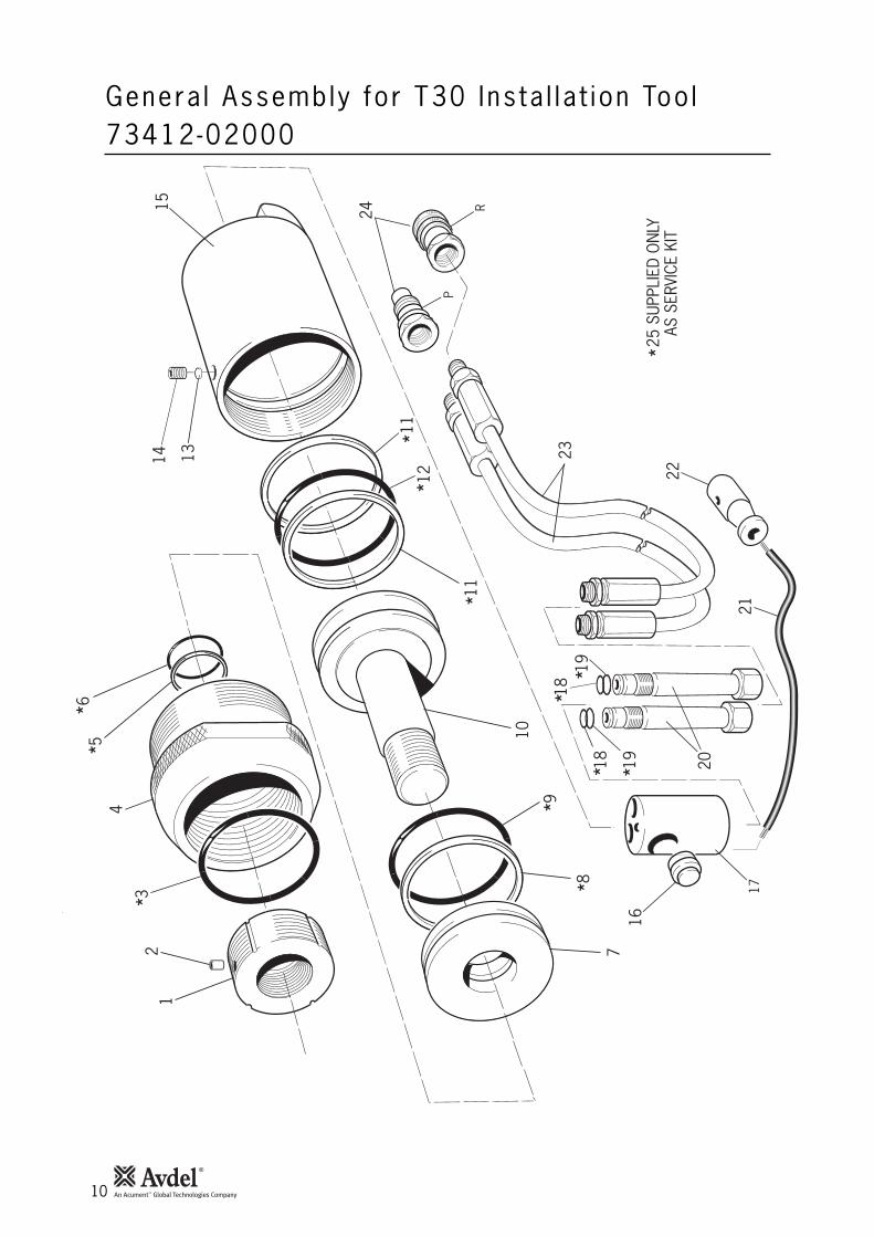
Item numbers in bold refer to the general assembly drawing and parts list on pages 10-11.
Dismant l ing Ins t ruct ions
Assembl ing the Too l
Main tenance

9
Ma in tenance
• Couple the short Tool Hoses directly onto a HydraPac or compatible Hydraulic Power Source. Note: Do not use long extension Hoses as these will prevent the air from escaping into the HydraPac.
• Plug in a HydraPac Test Trigger.
• Position the Tool so that the Piston Rod side faces vertically up.
• Cycle a few times.
• Reverse the vertical position and cycle again.
To B leed the Too l
10
Genera l Assembly for T30 Ins ta l l a t ion Too l73412-02000
14 13
15
11
1112
5
*
**
7
6
4
3
21
22
23
*
**
**
***
*
*
25 S
UPPL
IED
ON
LYAS
SER
VICE
KIT
16
24
P
R
18
1819
19 20
17
8
10
9
12
11
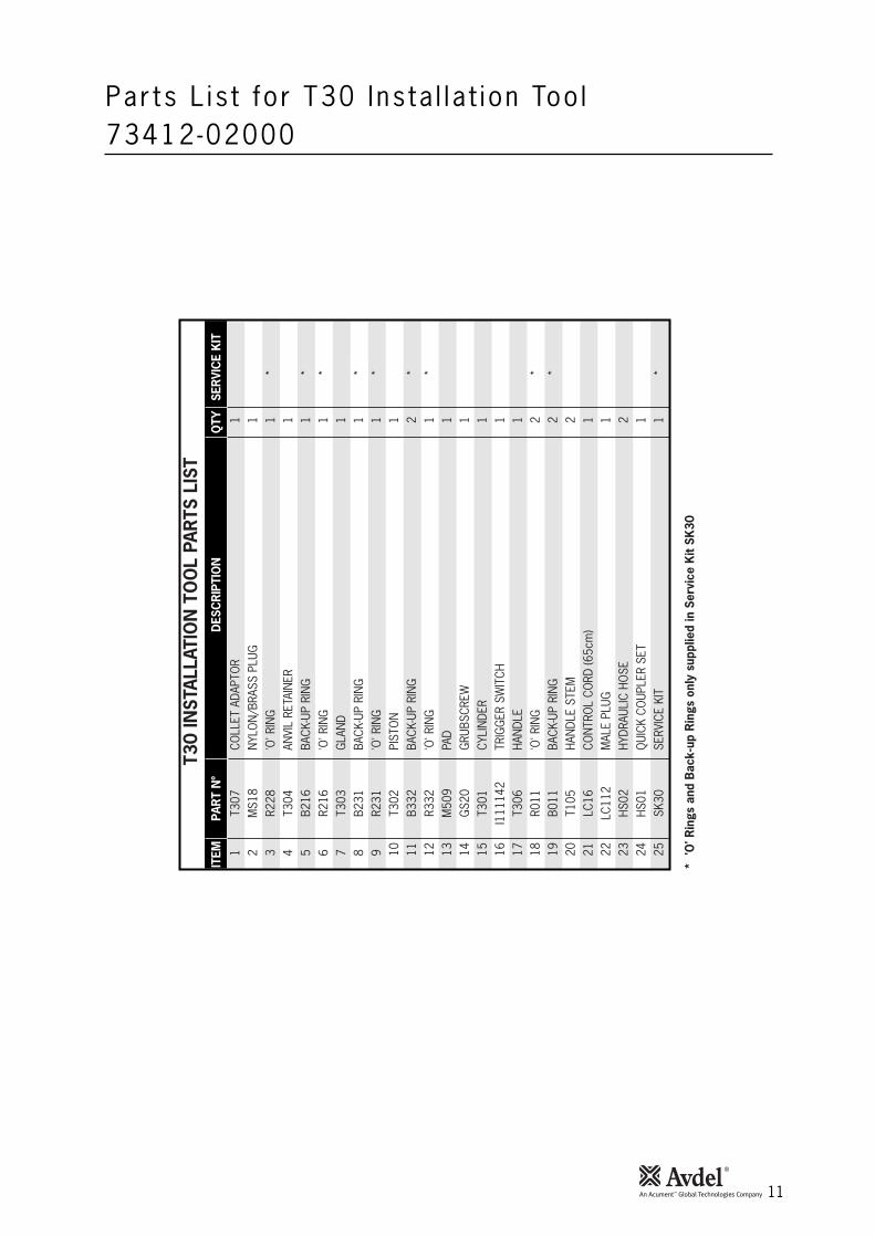
Par ts L is t for T30 Ins ta l l a t ion Too l73412-02000
ITEM
PAR
T N
ºD
ESC
RIP
TIO
NQ
TYSE
RVI
CE
KIT
T30
INST
ALLA
TIO
N T
OO
L PA
RTS
LIS
T
* 'O
' Rin
gs a
nd B
ack-
up R
ings
onl
y su
pplie
d in
Ser
vice
Kit
SK30
1T3
07CO
LLET
ADA
PTO
R1
2M
S18
NYL
ON
/BRA
SS P
LUG
13
R228
'O' R
ING
1*
4T3
04AN
VIL
RETA
INER
15
B216
BACK
-UP
RIN
G1
*6
R216
'O' R
ING
1*
7T3
03G
LAN
D1
8B2
31BA
CK-U
P RI
NG
1*
9R2
31'O
' RIN
G1
*10
T302
PIST
ON
111
B332
BACK
-UP
RIN
G2
*12
R332
'O' R
ING
1*
13M
509
PAD
114
GS2
0G
RUBS
CREW
115
T301
CYLI
NDE
R1
16I1
1114
2TR
IGG
ER S
WIT
CH1
17T3
06HA
NDL
E1
18R0
11'O
' RIN
G2
*19
B011
BACK
-UP
RIN
G2
*20
T105
HAN
DLE
STEM
221
LC16
CON
TRO
L CO
RD (6
5cm
)1
22LC
112
MAL
E PL
UG1
23HS
02HY
DRAU
LIC
HOSE
224
HS01
QUI
CK C
OUP
LER
SET
125
SK30
SERV
ICE
KIT
1*
12
• Check for oil leaks.
• Check the stroke of tool.
• Check for worn anvil indicated by score marks on the installed collar. This can also be confirmed by referring to the installed datain the fastener catalogue. Excessive wear can cause the anvil to rupture.
• Check function of pull pressure safety valve.
• Dismantle and clean the nose assembly especially the jaws.
• Check for oil leaks.
The tool should be completely dismantled and worn components replaced including 'O' rings and back-up rings.
• Open Ended Flat Spanners - 17, 19, 24 mm• Allen Keys - 4 mm, 6 mm
First Aid
SKIN:Under normal conditions skin irritation will not occur, contaminated skin should however be washed thoroughly with soap and water.Launder contaminated clothing.
ORAL:If swallowed and person is conscious give water or milk. Do not induce vomiting unless on advice of medical personnel. Take personto nearest medical centre.
EYES:Flush immediately with water for several minutes
DISPOSAL:Remove all spills with inert absorbent material. Ventilate spill area. Place contaminated materials in a disposable container anddispose in a manner consistent with local regulations.
Fire
FLASH POINT: 200°C.Extinguish with either dry chemical, foam or carbon dioxide. Do not enter confined space without self contained breathing apparatus.
Handling
Use barrier cream or oil resistant gloves.
Storage
Undercover and consistent with local regulations for inflammable material.
Dai ly
Weekly
Serv ice Too ls
Hydrau l ic O i l Genera l Safety Data
Every 1200 work ing hours (a t least once a year )
Serv ic ing the Too l
13
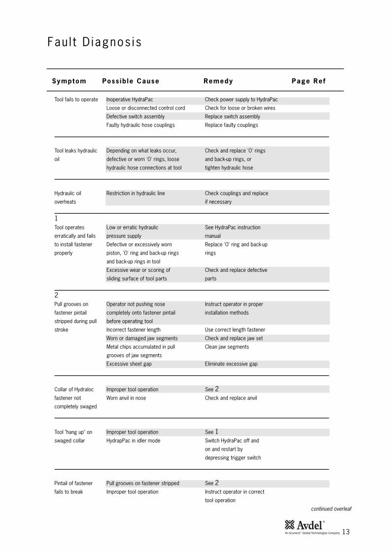
Tool fails to operate Inoperative HydraPac Check power supply to HydraPac
Loose or disconnected control cord Check for loose or broken wires
Defective switch assembly Replace switch assembly
Faulty hydraulic hose couplings Replace faulty couplings
Tool leaks hydraulic Depending on what leaks occur, Check and replace 'O' rings
oil defective or worn 'O' rings, loose and back-up rings, or
hydraulic hose connections at tool tighten hydraulic hose
Hydraulic oil Restriction in hydraulic line Check couplings and replace
overheats if necessary
1Tool operates Low or erratic hydraulic See HydraPac instruction
erratically and fails pressure supply manual
to install fastener Defective or excessively worn Replace 'O' ring and back-up
properly piston, 'O' ring and back-up rings rings
and back-up rings in tool
Excessive wear or scoring of Check and replace defective
sliding surface of tool parts parts
2Pull grooves on Operator not pushing nose Instruct operator in proper
fastener pintail completely onto fastener pintail installation methods
stripped during pull before operating tool
stroke Incorrect fastener length Use correct length fastener
Worn or damaged jaw segments Check and replace jaw set
Metal chips accumulated in pull Clean jaw segments
grooves of jaw segments
Excessive sheet gap Eliminate excessive gap
Collar of Hydraloc Improper tool operation See 2fastener not Worn anvil in nose Check and replace anvil
completely swaged
Tool "hang up" on Improper tool operation See 1swaged collar HydrapPac in idler mode Switch HydraPac off and
on and restart by
depressing trigger switch
Pintail of fastener Pull grooves on fastener stripped See 2fails to break Improper tool operation Instruct operator in correct
tool operation
continued overleaf
Fau l t D iagnos is
Symptom Poss ib le Cause Remedy Page Ref

14
Jaw segments do not Improper operation of jaw Check internal parts of the
maintain proper follower collet for wear i.e. jaws,
position in collet follower, cushion and end cap.
Clean before reassembling
Hydraulic couplers Defective or worn 'O' ring in Replace 'O' ring and back-up ring
leak oil coupler body
Pintail fails to release Incorrect assembly of Nose Refer to nose assenbly table on page 5
Fau l t D iagnos is
Symptom Poss ib le Cause Remedy Page Ref
15
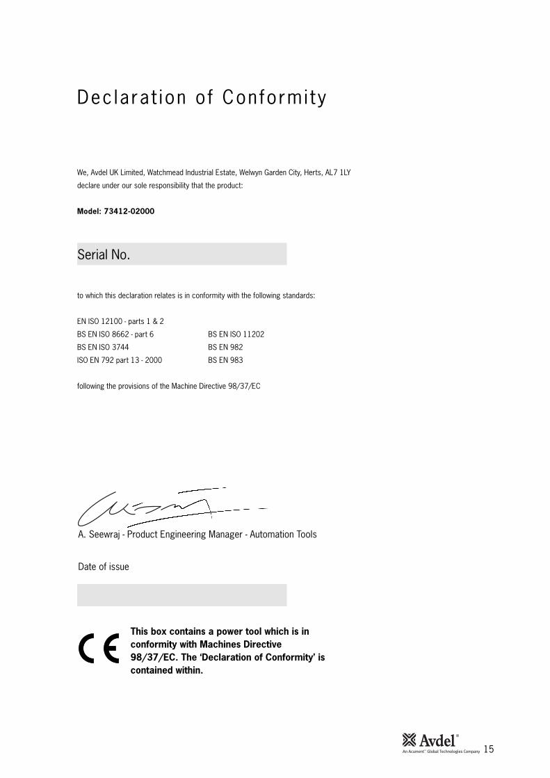
This box contains a power tool which is inconformity with Machines Directive98/37/EC. The ‘Declaration of Conformity’ iscontained within.
Dec lara t ion o f Conformi ty
We, Avdel UK Limited, Watchmead Industrial Estate, Welwyn Garden City, Herts, AL7 1LY
declare under our sole responsibility that the product:
Model: 73412-02000
Serial No. ................................................
to which this declaration relates is in conformity with the following standards:
EN ISO 12100 - parts 1 & 2
BS EN ISO 8662 - part 6 BS EN ISO 11202
BS EN ISO 3744 BS EN 982
ISO EN 792 part 13 - 2000 BS EN 983
following the provisions of the Machine Directive 98/37/EC
Date of issue
A. Seewraj - Product Engineering Manager - Automation Tools
Manual No. Issue Change Note No. Date
B 07/044 02/07
B2 07/103 03/07
B3 08/131 06/0807900-00821
www.avdel-global.com
© 2
00
8 A
cu
me
nt
Inte
lle
ctu
al
Pro
pe
rtie
s,
LL
C J
un
e 0
8.AUSTRALIA
Acument Australia Pty Ltd.
891 Wellington Road
Rowville, Victoria 3178
Tel: +61 3 9765 6400
Fax: +61 3 9765 6445
Email: [email protected]
CANADA
Avdel Canada, a Division of Acument
Canada Limited.
87 Disco Road
Rexdale
Ontario M9W 1M3
Tel: +1 416 679 0622
Fax: +1 416 679 0678
Email: [email protected]
CHINA
Acument China Ltd.
RM 1708, 17/F., Nanyang Plaza,
57 Hung To Rd., Kwun Tong
Hong Kong
Tel: +852 2950 0631
Fax: +852 2950 0022
Email: [email protected]
FRANCE
Avdel France S.A.S.
33 bis, rue des Ardennes
BP4
75921 Paris Cedex 19
Tel: +33 (0) 1 4040 8000
Fax: +33 (0) 1 4208 2450
Email: [email protected]
GERMANY
Avdel Deutschland GmbH
Klusriede 24
30851 Langenhagen
Tel: +49 (0) 511 7288 0
Fax: +49 (0) 511 7288 133
Email: [email protected]
ITALY
Avdel Italia S.r.l.
Viale Lombardia 51/53
20047 Brugherio (MI)
Tel: +39 039 289911
Fax: +39 039 2873079
Email: [email protected]
JAPAN
Acument Japan Kabushiki Kaisha
Center Minami SKY,
3-1 Chigasaki-Chuo, Tsuzuki-ku,
Yokohama-city, Kanagawa Prefecture
Japan 224-0032
Tel: +81 45 947 1200
Fax: +81 45 947 1205
Email: [email protected]
SINGAPORE
Acument Asia Pacific (Pte) Ltd.
#05-03/06 Techlink
31 Kaki Bukit Road 3
Singapore, 417818
Tel: +65 6840 7431
Fax: +65 6840 7409
Email: [email protected]
SOUTH KOREA
Acument Korea Ltd.
212-4, Suyang-Ri,
Silchon-Eup, Kwangju-City,
Kyunggi-Do, Korea, 464-874
Tel: +82 31 798 6340
Fax: +82 31 798 6342
Email: [email protected]
SPAIN
Avdel Spain S.A.
C/ Puerto de la Morcuera, 14
Poligono Industrial Prado Overa
Ctra. de Toledo, km 7,8
28919 Leganés (Madrid)
Tel: +34 (0) 91 3416767
Fax: +34 (0) 91 3416740
Email: [email protected]
UNITED KINGDOM
Avdel UK Limited
Pacific House
2 Swiftfields
Watchmead Industrial Estate
Welwyn Garden City
Hertfordshire
AL7 1LY
Tel: +44 (0) 1707 292000
Fax: +44 (0) 1707 292199
Email: [email protected]
USA
Avdel USA LLC
614 NC Highway 200 South
Stanfield,
North Carolina 28163
Tel: +1 704 888-7100
Fax: +1 704 888-0258
Email: [email protected]