Embed Size (px)
Citation preview
Kit content
- Central part : top and bottom delivered as one part- Gel profiles : 4 pcs- O-ring seal : 2 pcs- 4-out cable separator : 1 pc (large sizes only)- Plugs for unused cable ports- Axial pull tapes + tie wraps- Gel sealing tape- Cleaning tissue- Bolts and washers- Measuring tape- Installation instruction
Size selection chart (dimensions:mm)
Description Max.splice Max.sheath Cable Cables IN Cables OUT Typical splicediam. opening configurations max.diam. max.diam. capacity
T2C 100-450-2/4 100 450 2 in - 4 out 2 x 40 4 x 40 300p
Safety rules
Check manhole for presence of gas and followlocally prescribed precautions.
Installation tools
- Cable marking pen- Pair of scissors- Screw driver- Wrench- Cutting pliers- PVC tape
Re-entry kit
A re-entry kit can ordered separately to add orreplace cables. CommScope reference: e.g.T2C-68-RE.The re-entry kit includes gel sealing tapes,axial pull tapes, measuring tape and tiewraps.
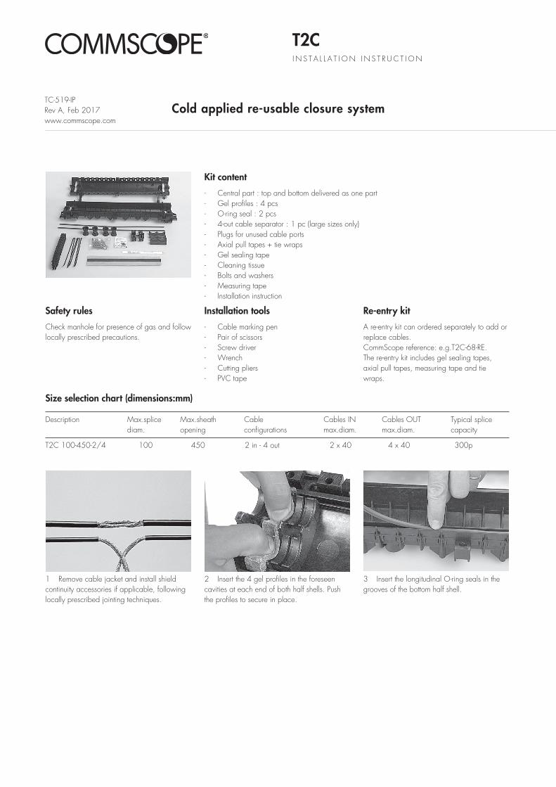
1 Remove cable jacket and install shieldcontinuity accessories if applicable, follo winglocally prescribed jointing techniques.
2 Insert the 4 gel profiles in the foreseencavities at each end of both half shells. Pushthe profiles to secure in place.
3 Insert the longitudinal O-ring seals in thegrooves of the bottom half shell.
TC-519-IPRev A, Feb 2017www.commscope.com
T2CI N S T A L L A T I O N I N S T R U C T I O N
Cold applied re-usable closure system
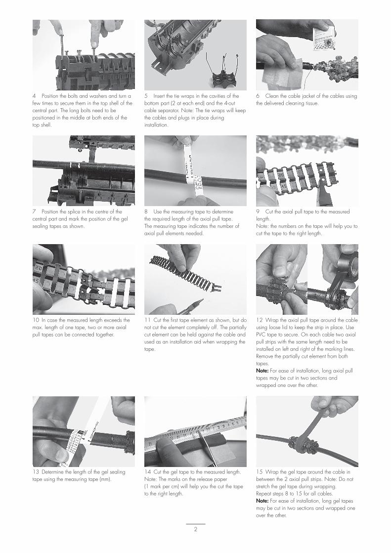
4 Position the bolts and washers and turn afew times to secure them in the top shell of thecentral part. The long bolts need to bepositioned in the middle at both ends of thetop shell.
5 Insert the tie wraps in the cavities of thebottom part (2 at each end) and the 4-outcable separator. Note: The tie wraps will keepthe cables and plugs in place duringinstallation.
6 Clean the cable jacket of the cables usingthe delivered cleaning tissue.
7 Position the splice in the centre of thecentral part and mark the position of the gelsealing tapes as shown.
8 Use the measuring tape to determinethe required length of the axial pull tape. The measuring tape indicates the number ofaxial pull elements needed.
10 In case the measured length exceeds themax. length of one tape, two or more axialpull tapes can be connected together.
11 Cut the first tape element as shown, but donot cut the element completely off. The partiallycut element can be held against the cable andused as an installation aid when wrapping thetape.
12 Wrap the axial pull tape around the cableusing loose lid to keep the strip in place. UsePVC tape to secure. On each cable two axialpull strips with the same length need to beinstalled on left and right of the marking lines.Remove the partially cut element from bothtapes.Note: For ease of installation, long axial pulltapes may be cut in two sections andwrapped one over the other.
13 Determine the length of the gel sealingtape using the measuring tape (mm).
14 Cut the gel tape to the measured length.Note: The marks on the release paper (1 mark per cm) will help you the cut the tapeto the right length.
15 Wrap the gel tape around the cable inbetween the 2 axial pull strips. Note: Do notstretch the gel tape during wrapping.Repeat steps 8 to 15 for all cables.Note: For ease of installation, long gel tapesmay be cut in two sections and wrapped oneover the other.
9 Cut the axial pull tape to the measuredlength. Note: the numbers on the tape will help you tocut the tape to the right length.
2
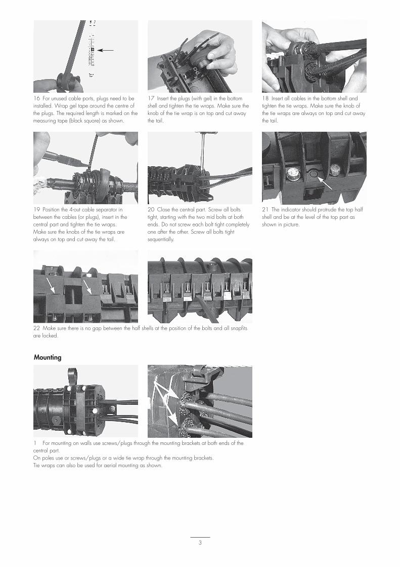
16 For unused cable ports, plugs need to beinstalled. Wrap gel tape around the centre ofthe plugs. The required length is marked on themeasuring tape (black square) as shown.
17 Insert the plugs (with gel) in the bottomshell and tighten the tie wraps. Make sure theknob of the tie wrap is on top and cut awaythe tail.
18 Insert all cables in the bottom shell andtighten the tie wraps. Make sure the knob ofthe tie wraps are always on top and cut awaythe tail.
19 Position the 4-out cable separator inbetween the cables (or plugs), insert in thecentral part and tighten the tie wraps.Make sure the knobs of the tie wraps arealways on top and cut away the tail.
21 The indicator should protrude the top halfshell and be at the level of the top part asshown in picture.
20 Close the central part. Screw all boltstight, starting with the two mid bolts at bothends. Do not screw each bolt tight completelyone after the other. Screw all bolts tightsequentially.
22 Make sure there is no gap between the half shells at the position of the bolts and all snapfitsare locked.
1 For mounting on walls use screws/plugs through the mounting brackets at both ends of thecentral part.On poles use or screws/plugs or a wide tie wrap through the mounting brackets.Tie wraps can also be used for aerial mounting as shown.
Mounting
3
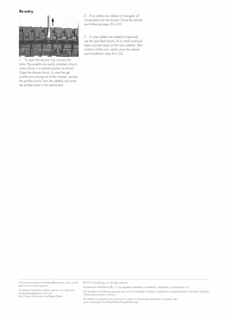
1 To open the closure, first unscrew thebolts. The snapfits are easily unlocked using ascrew driver in a vertical position as shown.Open the closure slowly. In case the gelprofiles are coming out of the cavities, removethe profiles slowly from the cable(s) and insertthe profiles back in the central part.
2 If no cables are added or changed, allcomponents can be re-used. Close the centralpart following steps 20 to 22.
3 In case cables are added or replaced,use the specified re-entry kit to install axial pulltapes and gel tapes on the new cable(s). Afterinsertion of the new cables close the centralpart (installation steps 8 to 22).
Re-entry
© 2017 CommScope, Inc. All rights reserved.
All trademarks identified by ® or ™ are registered trademarks or trademarks, respectively, of CommScope, Inc.
This document is for planning purposes only and is not intended to modify or supplement any specifications or warranties relating to CommScope products or services.
This product is covered by one ore more U.S. patents or their foreign equivalents. For patents, see: www.commscope.com/ProductPatent/ProductPatent.aspx.
To find out more about CommScope® products, visit us on the web at www.commscope.com
For technical assistance, customer service, or to report any missing/damaged parts, visit us at: http://www.commscope.com/SupportCenter


![Instruction Sheet 408-8925 - CommScope.com · universal adapter. — Professional Fiber Optic Connector Inspection Kit 2064651–[ ] (Instruction Sheet 408–10263) — Fiber Optic](https://img.pdfslide.us/doc/110x75/601e9c34e5cb6f7b3647a891/instruction-sheet-408-8925-universal-adapter-a-professional-fiber-optic-connector.jpg)