Embed Size (px)
Citation preview

Evaluation and Comparison of Two Air Bearing Linear Translation StagesPresented byIan Veldman
Test & Measurement ConferenceOctober 2015

Topics
• Introduction
• What is this thing “air bearing linear translation stage”?
• Comparison of commercial LTS and new design LTS
• Comparison Parameters
• Measurement Configuration/Procedures
• Measurement Data
• Evaluation of Results
• Conclusions

Air Bearing Linear Translation Stages
• It is a mechanical system that allows for linear, frictionless recti-linear motion over large distances
• The Commercial LTS Characteristics?
• A square bearing traversing 150 mm on a square support beam
• Support beam dimensions: 35 mm X 35 mm
• Mounting surface: 80 mm X 80 mm
• Areas For Improvement
• Ridged mounting to electrodynamic exciter using a M4 bolt
• Height of the accelerometer above the centre of movement
• Requirement of an angle bracket to mount accelerometer
Air Bearing Linear Translation Stages
• NMISA LTS Characteristics?
• Three cylindrical porous carbon bearings traversing 150 mm on two precision beams
• Improvements
• Ball joint mount between LTS and Exciter
• Accelerometer mount in line with centre of movement
• No additional hardware required to mount accelerometer
Performance Comparison of LTSs
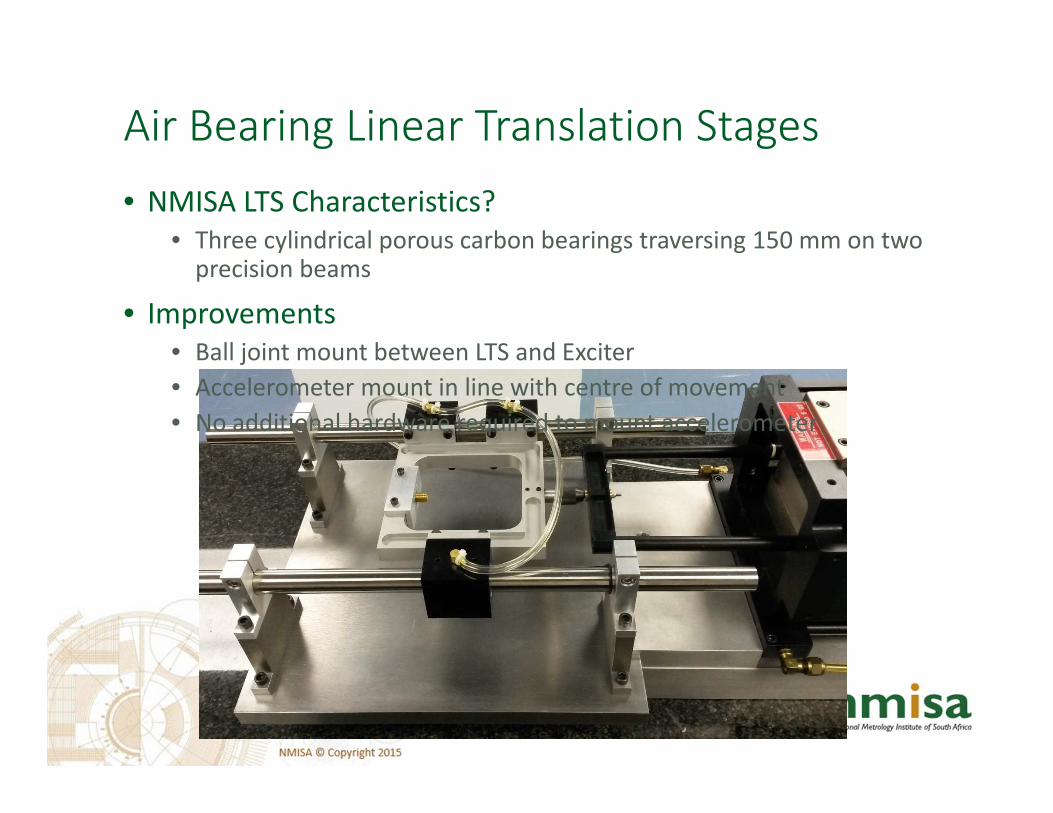
• The linearity of the movement of the two LTSs were characterised over the 150 mm travel in terms of:
• Straightness
• The amount of travel in the x-axis direction over the full travel in the z-axis direction
• Flatness
• The amount of travel in the y-axis direction over the full travel in the z-axis direction

Performance Comparison LTSs
• Roll
• The amount of rotational movement in the x-y plane over the full travel in the z-axis direction
• Pitch
• The amount of rotational movement in the y z plane over the full travel in the z-axis direction
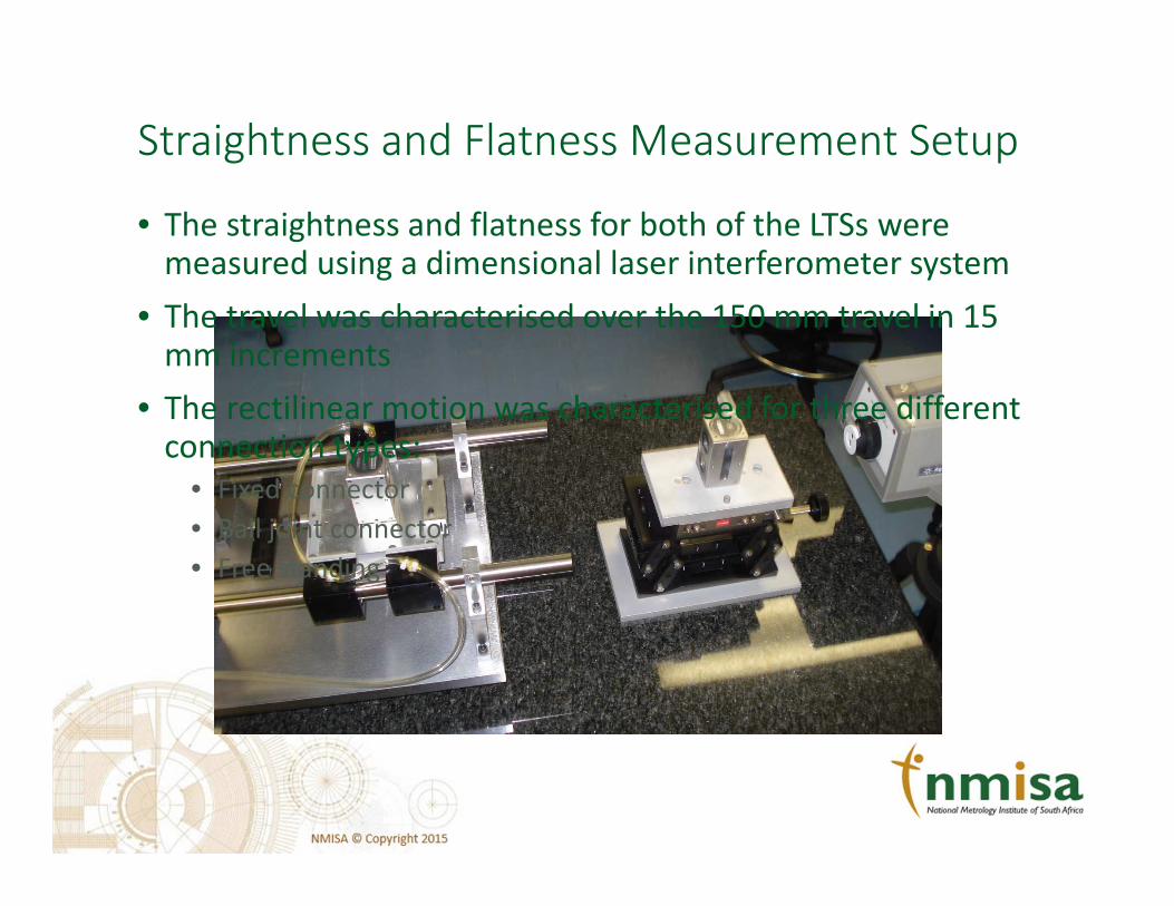
Straightness and Flatness Measurement Setup
• The straightness and flatness for both of the LTSs were measured using a dimensional laser interferometer system
• The travel was characterised over the 150 mm travel in 15 mm increments
• The rectilinear motion was characterised for three different connection types:
• Fixed connector
• Ball joint connector
• Free standing
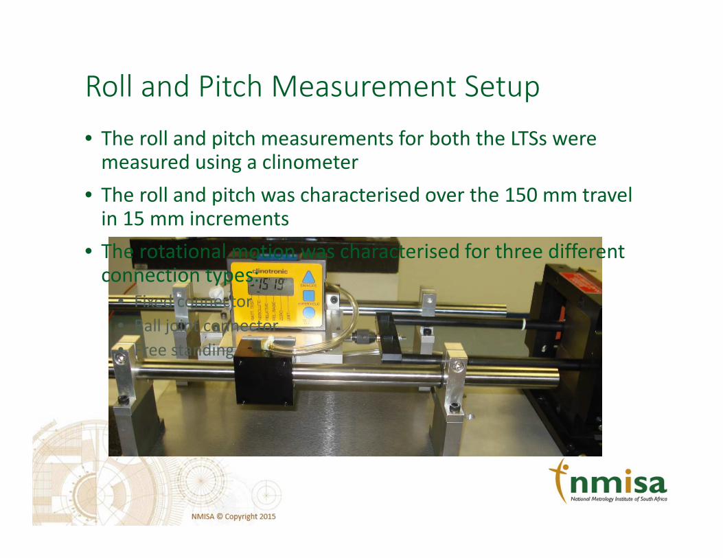
Roll and Pitch Measurement Setup
• The roll and pitch measurements for both the LTSs were measured using a clinometer
• The roll and pitch was characterised over the 150 mm travel in 15 mm increments
• The rotational motion was characterised for three different connection types:
• Fixed connector
• Ball joint connector
• Free standing

Transverse Motion Measurement Setup
• Transverse acceleration
• Is the acceleration in the x- and y axis, relative to the acceleration in the z-axis
• The x- and y-axis acceleration were measured using two accelerometers
• The z-axis acceleration was measured using a laser vibrometer
• The measurements were performed over the frequency range 1 Hz to 100 Hz in octave frequency steps
• The transverse acceleration results were evaluated against the requirements specified in ISO 16063-11
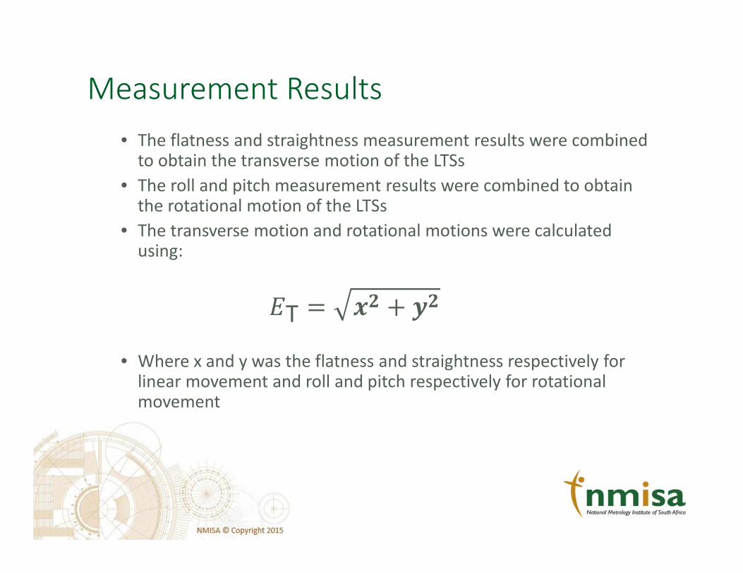
Measurement Results
• The flatness and straightness measurement results were combined to obtain the transverse motion of the LTSs
• The roll and pitch measurement results were combined to obtain the rotational motion of the LTSs
• The transverse motion and rotational motions were calculated using:
�T � �� � ��
• Where x and y was the flatness and straightness respectively for linear movement and roll and pitch respectively for rotational movement
Measurement Results – Rectilinear Motion
-5.0
-4.5
-4.0
-3.5
-3.0
-2.5
-2.0
-1.5
-1.0
-0.5
0.0
0 20 40 60 80 100 120 140
Dis
pla
cem
ne
nt
(µm
)
Position
(mm)
Commercial Linear Translation Stage
Transverse Motion
Fixed Ball Joint Not Connected
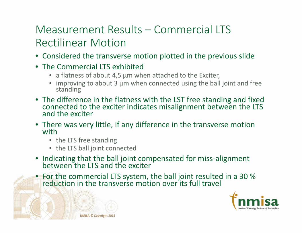
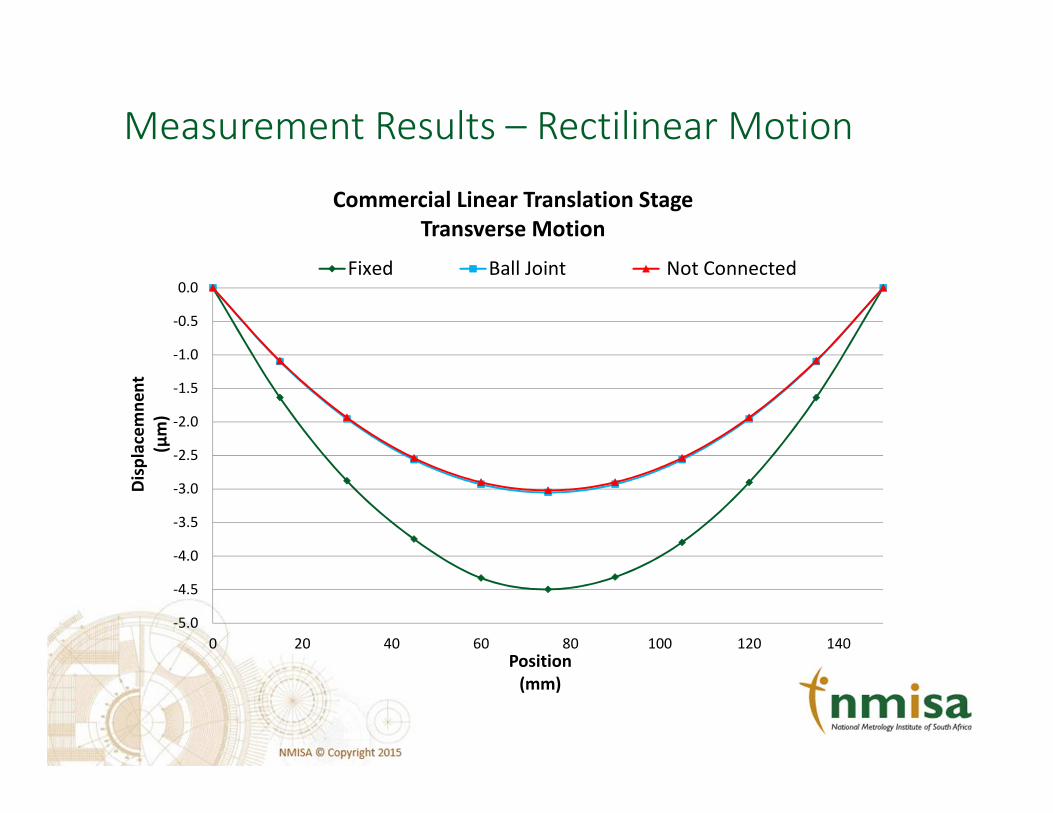
Measurement Results – Commercial LTS
Rectilinear Motion• Considered the transverse motion plotted in the previous slide
• The Commercial LTS exhibited• a flatness of about 4,5 μm when attached to the Exciter,• improving to about 3 μm when connected using the ball joint and free
standing
• The difference in the flatness with the LST free standing and fixed connected to the exciter indicates misalignment between the LTS and the exciter
• There was very little, if any difference in the transverse motion with
• the LTS free standing• the LTS ball joint connected
• Indicating that the ball joint compensated for miss-alignment between the LTS and the exciter
• For the commercial LTS system, the ball joint resulted in a 30 % reduction in the transverse motion over its full travel
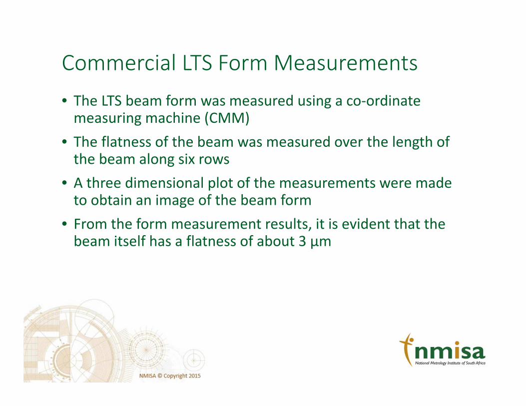
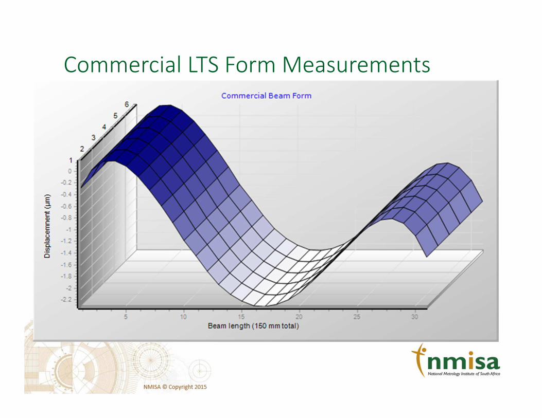
Commercial LTS Form Measurements
• The LTS beam form was measured using a co-ordinate measuring machine (CMM)
• The flatness of the beam was measured over the length of the beam along six rows
• A three dimensional plot of the measurements were made to obtain an image of the beam form
• From the form measurement results, it is evident that the beam itself has a flatness of about 3 μm
Commercial LTS Form Measurements

Measurement Results – Rectilinear Motion
-7
-6
-5
-4
-3
-2
-1
0
0 20 40 60 80 100 120 140
Dis
pla
cem
en
t
(µm
)
LTS Position
(mm)
NMISA Linear Translation Stage
Transverse Motion
Tight Loose Not Connected

Measurement Results – NMISA LTS Rectilinear
Motion
• Considered the transverse motion plotted in the previous slide
• The NMISA LTS exhibited a flatness of
• about 4,5 μm when tightly attached to the exciter using the ball join
• about 6 μm when loosely connected using the ball joint and free standing
• about 6 μm when free standing
• This difference in the linear motion is an indication that some misalignment exists between the LTS and the exciter
• There was very little difference in the transverse motion with the NMISA LTS free standing and the LTS connected to the exciter using the ball joint
Measurement Results – Rotational Motion
-0.3
-0.2
-0.1
0.0
0.1
0.2
0.3
0 20 40 60 80 100 120
Tra
nsv
ers
e R
ota
tio
n
(min
)
Position
(mm)
Commercial Linear Translation Stage
Rotational MotionFixed Ball Joint Not Connected
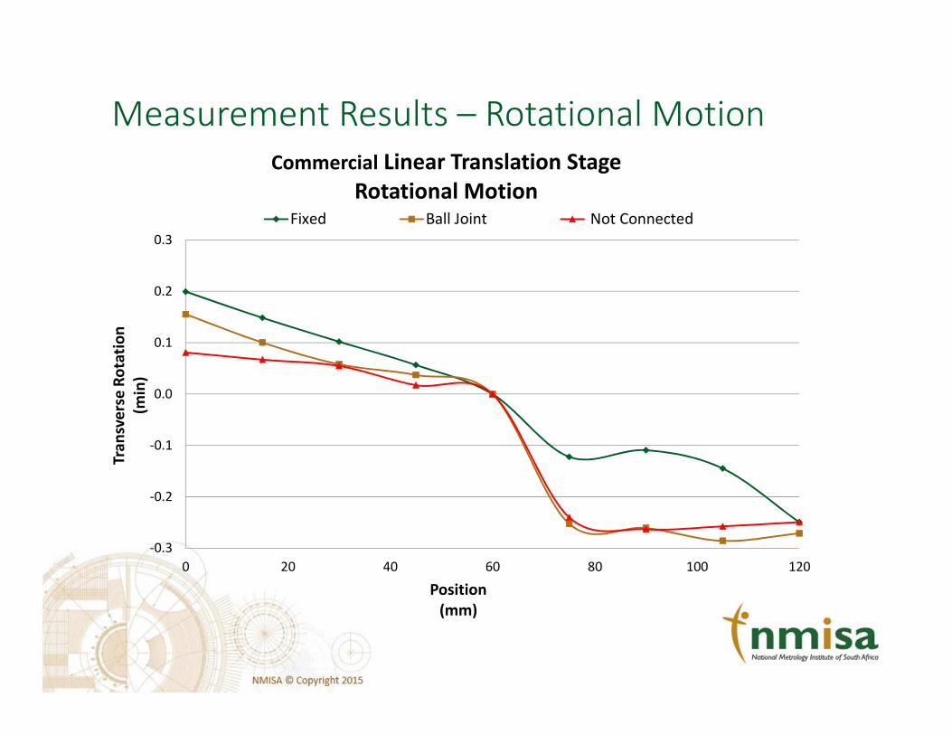
Measurement Results – Commercial LTS
Rotational Motion
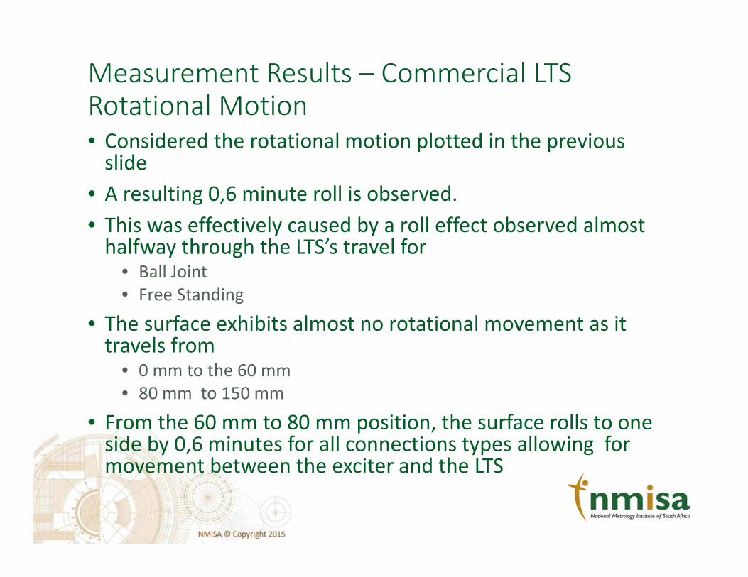
• Considered the rotational motion plotted in the previous slide
• A resulting 0,6 minute roll is observed.
• This was effectively caused by a roll effect observed almost halfway through the LTS’s travel for
• Ball Joint
• Free Standing
• The surface exhibits almost no rotational movement as it travels from
• 0 mm to the 60 mm
• 80 mm to 150 mm
• From the 60 mm to 80 mm position, the surface rolls to one side by 0,6 minutes for all connections types allowing for movement between the exciter and the LTS
Measurement Results – Rotational Motion
-0.3
-0.1
0.1
0.3
0.5
0.7
0.9
1.1
0 20 40 60 80 100 120 140
Tra
nsv
ers
e R
ota
tio
n
(min
)
LTS Position
(mm)
NMISA Linear Translation Stage
Rotational Motion
Tight Loose Not Connected

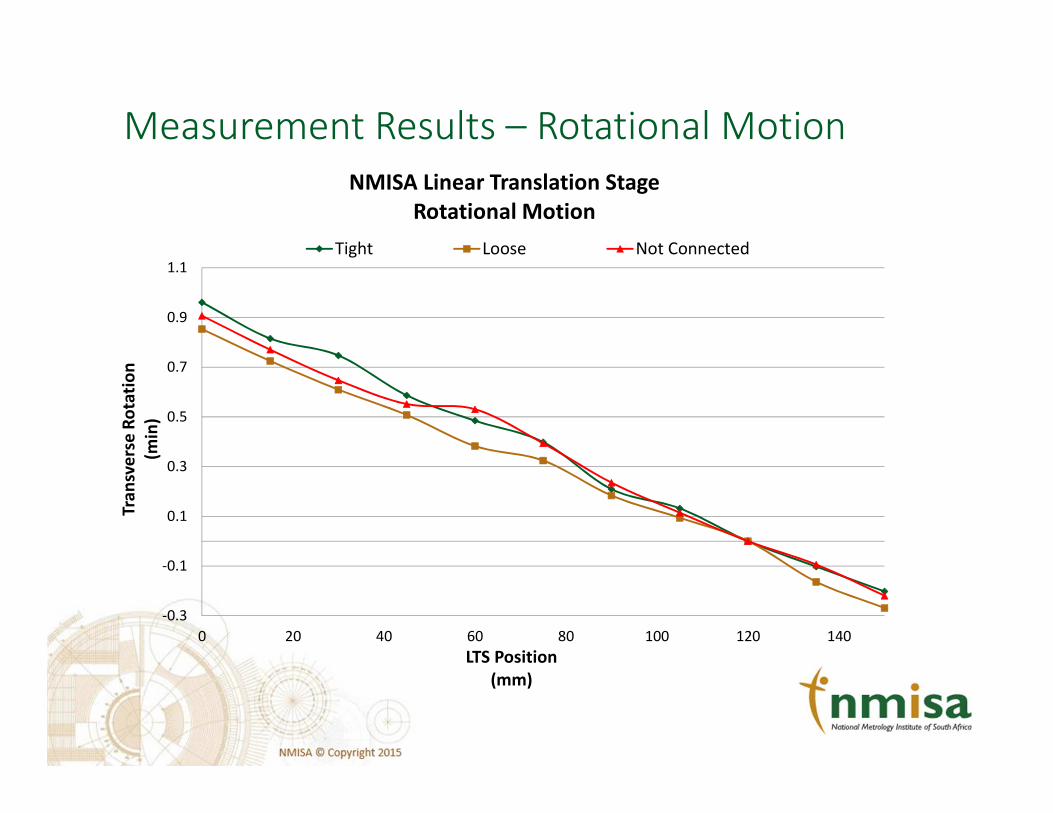
Measurement Results – NMISA LTS Rotational
Motion
• Considered the rotational motion plotted in the previous slide
• As the LTS traverses over the 150 mm distance, one observes a constant rotational motion of
• 0,45”/mm
• approximately 1’ over 150 mm

Measurement Results
Transverse Acceleration
0
2
4
6
8
10
12
1 10 100
Re
lati
ve
Tra
nse
ve
rse
Acc
ele
rati
on
Frequency
(Hz)
Measured Transverse Acceleration
ISO 16063 NMISA LTS Commercial LTS

Measurement Results – Transverse
Acceleration
• In the previous graph, green line depicts
• the Commercial LTS transverse acceleration
• the blue line depicts the NMISA LTS transverse acceleration
• the red line represents the requirements for the vibration exciter specified in ISO 16063-11 for primary accelerometer calibration
• The Commercial LTS only met the ISO requirements for frequencies above 10 Hz
• The NMISA LTS met the ISO requirements for frequencies from 1 Hz to 100 Hz

Conclusions
• The translation motions of two air-bearing linear translation stages of different design and geometry, were investigated
• The influence of the connection mechanism linking the LTS to the Exciter was also investigated
• From the data, it was evident that a ridged connection introduced non-linearities which exist as a result of misalignment between the Exciter and LTS
• The ball joint “absorbed” minor misalignment errors
• The NMISA design showed noticeable improvement in the transverse motion measurements, meeting the ISO 16063-11 requirements for vibration exciters

Thank you for your attention!


![The origin of nickel bearing clay ore, Yap Island. Mitsubishi Mining Co., Ltd. [Translation 180]](https://img.pdfslide.us/doc/110x75/568bdc2a1a28ab2034b13268/the-origin-of-nickel-bearing-clay-ore-yap-island-mitsubishi-mining-co-ltd.jpg)