Embed Size (px)
Citation preview

T2™Supracondylar Nailing System
Operative Technique
2 3
Supracondylar Nailing System
Prof. Dr. med. Volker BührenChief of Surgical ServicesMedical Director of Murnau Trauma CenterMurnauGermany
Dean C. Maar, M.D.Methodist Hospital - IndianapolisIndianapolisIndianaUSA
James W. Maxey, M.D.Orthopedic Institute of IllinoisPeoriaIllinoisUSA
This publication sets forth detailed recommended procedures for using Stryker Trauma devices and instruments.
It offers guidance that you should heed, but, as with any such technical guide, each surgeon must considerthe particular needs of each patient and make appropriate adjustments when and as required.
A workshop training is required prior to first surgery.
Contributing Surgeons :
2 3
1. Introduction 4
1.1. Implant Features 4
1.2. Instrument Features 6
1.2.1. Target Device Features 6
1.2.1.1. Target Device Features (Targeting Arm, SCN) 6
1.2.1.2. Target Device Features (Targeting Arm Proximal, SCN) 6
2. Locking Options 8
3. Indications 9
4. Pre-operative Planning 9
5. Operative Technique 10
5.1. Patient Positioning 10
5.2. Incision 10
5.3. Entry Point 11 5.4. Reamed Technique 12
5.5. Nail Selection 13
5.6. Nail Insertion 14
5.7. Guided Distal Locking Mode 15
5.7.1. Proximal Locking - Fully Threaded Screw 15
5.7.2. Proximal Locking - Condyle Screw 17
5.7.3. Oblique Locking - Fully Threaded Screw 18
5.7.4. Distal Locking - Fully Threaded or Condyle Screw 19
5.8. Freehand Proximal Locking 20
5.9. Guided Proximal Locking SCN Short 21
5.10. End Cap Insertion 22
5.11. Nail Removal 23
Ordering Information - Implants 24
Ordering Information - Instruments 26
Contents

4 5
Over the past several decades ante-grade femoral nailing has become the treatment of choice for most femoral shaft fractures. Recently, retrograde femoral nailing has increased in popularity, expanding the use of intramedullary nails. Complicated multiple trauma injuries, ipsilateral femoral neck and shaft fractures, associated pelvic and acetabular fractures, ipsilateral femoral and tibial shaft fractures, supracondylar and intercondylar fractures, may be better managed by utilizing retrograde femoral nailing techniques.
In addition to the T2™ Femoral Nailing System, Stryker Trauma developed the T2™ Supracondylar Nail (SCN) for the treatment of complex distal femoral fractures.
The T2™ Supracondylar Nailing System offers the advantages of a unique locking configuration and targeting concept, allowing superior fixation in the distal femur, using the already established T2 instrument platform and locking screws.
1.1. Implant Features
The T2™ SCN System is the realiza-tion of superior biomechanical intramedullary stabilization using small caliber, strong and cannulated implants for internal fixation of the femur.
According to the fracture type, the system offers the option of a static locking mode with 3 plane fixation.
The design of the T2™ SCN System is universal for left and right indications.
Two implant versions are available:
Short version:Proximal Targeting via Target Device
Long version: Proximal Locking via Freehand Locking
Nails:T2™ SCN Short versionLength : 170 & 200mm
T2™ SCN Long versionLength: 240−440mm in 20mm increments
Introduction
SCN End Cap:One End Cap for all T2™ SCN is available to lock the most distal Locking Screw in order to avoid lateral movement of the nail and to prevent bony ingrowth.This feature creates a fixed angle between the nail and Locking Screw.
Common 5mm cortical screws simplify the surgical procedure and promote a minimally invasive approach. Fully Threaded Screws are available for standard locking procedures.
Special Condyle Screws with adjustable screw heads for improved fit are designed to fix fragments in the condyle area. They provide compres-sion of intracondylar fractures and increased stability in distal fracture fragment.
All implants of the T2™ SCN System are made of Type II anodized titanium alloy (Ti6Al4V) for enhanced biomechanical and biomedical performance.
1. Introduction
4 5
Technical Details
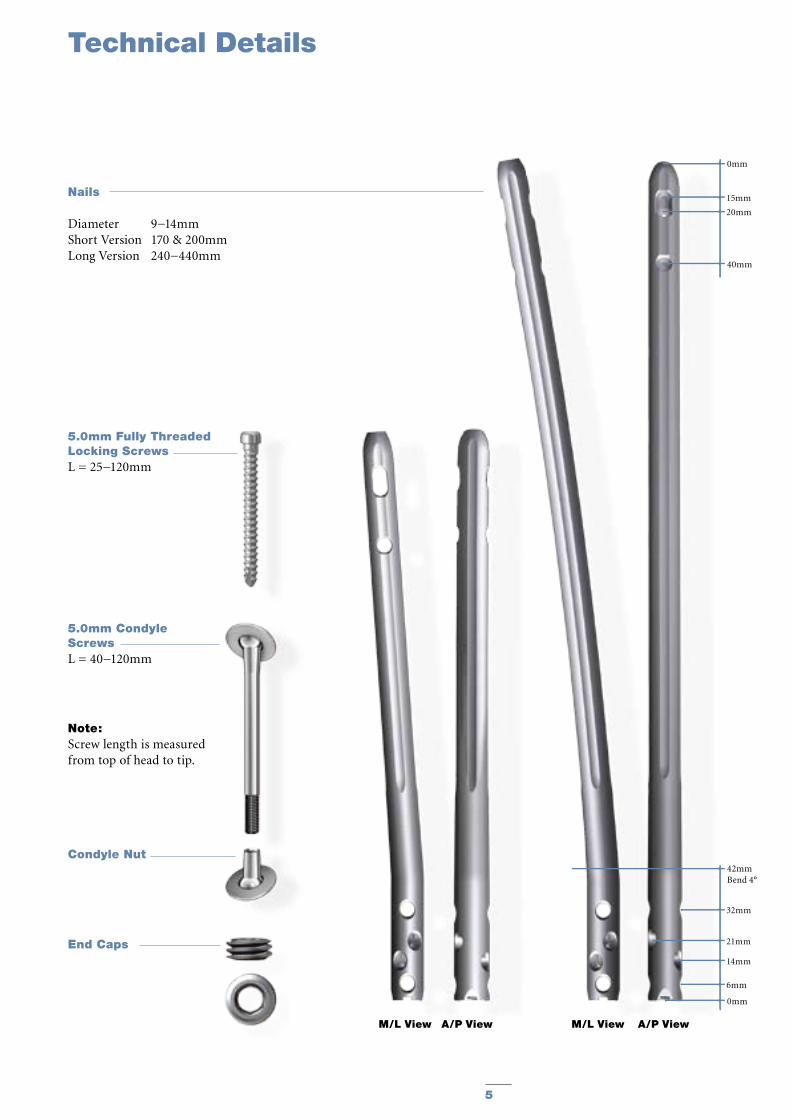
Nails
Diameter 9−14mmShort Version 170 & 200mmLong Version 240−440mm
End Caps
M/L View A/P View M/L View A/P View
5.0mm Fully Threaded Locking ScrewsL = 25−120mm
5.0mm Condyle ScrewsL = 40−120mm
0mm
15mm
20mm
40mm
0mm
6mm
14mm
42mmBend 4°
21mm
32mm
Note: Screw length is measured from top of head to tip.
Condyle Nut

6 7
The major advantage of the instrument system is a breakthrough in the integration of the instrument platform which can be used not only for the complete T2™ Nailing System, including the T2™ SCN System, but will be the platform for all future nailing systems, reducing complexity and inventory.
The instrument platform features ergonomically styled targeting devices, and provides advanced precision while maintaining ease of use.
Additionally, the instruments are color, number and symbol coded indicating their usage during the surgical procedure.
Color and number coding indicates the step during the procedure in which the instrument is used. This color code system is marked on the trays to easily identify the correct instrument.
Symbol coding on the instruments indicates the type of procedure and must not be mixed.
Symbol
= Long instruments
Drills
Drills feature a color coded ring:
4.2mm = GreenFor Fully Threaded Screws 5.0mm
5.0mm = BlackFor Condyle Screws
The Targeting Arm for the T2™ SCN is designed with one locking hole for all locking screws to be placed in the distal femur (Fig. 1).
These are the locking holes in the distal femur:
1. Proximal Transverse Distal Condylar Locking
2. Oblique Condylar Locking3. Oblique Condylar Locking4. Distal Transverse Distal Condylar
Locking
The Targeting Arm can be rotated and axially moved along the Nail Adapter. The Locking Window, together with the corresponding positions on the Targeting Arm indicates the appropriate locking position.
After the required locking position is reached, the Targeting Arm is locked by tightening the thumb screw.
Note:To avoid mis-drilling the Targeting Arm can be locked in the dedicated position only.
An additional Target Device for the T2™ SCN Short version is available for the proximal locking options: The name of this Target Device is: Targeting Arm Proximal, SCN (Fig. 2).
After the required locking position is reached, the Targeting Arm is locked by tightening the thumb screw.
The Targeting Arm Proximal, SCN, is designed to provide guided proximal locking for the T2 SCN Short version 170 & 200mm.
Instruments
Step Color NumberOpening Red 1Reduction Brown 2Nail Introduction Green 3Guided Locking Light Blue 4Freehand Locking Dark Blue 5
1.2. Instrument Features 1.2.1. Target Device Features
1.2.1.1. Target Device Features (Targeting Arm, SCN)
1.2.1.2. Target Device Features (Targeting Arm Proximal, SCN)

6 7
Nail Adapter, SCN (1806-3301)
Proximal Transverse Distal Condylar Locking
Oblique Condylar LockingOblique Condylar Locking
Distal Transverse Distal Condylar Locking
Nail Holding Screw, SCN (1806-3307)
Targeting Arm, SCN (1806-3302)
Target Hole
Safety Clip
Thumb Screw
Locking Window
1234
Targeting Arm Proximal, SCN (1806-3305) Fig. 1
Fig. 2
Instruments

T2™ SCN Short Nail
8 9
Proximal Locking OptionsT2™ SCN Long versionWhen treating distal fractures, two A/P screws should be used in static position when possible (Fig. 6). Proximal locking may be done in either static or dynamic mode depending on surgeon preference. These holes are targeted freehand.
Proximal Locking OptionsT2™ SCN Short versionWhen treating distal fractures, two M/L locking screws should be used when possible (Fig. 7). Both screws can be placed directly through the Targeting Arm Proximal, SCN.
Fig. 5
Distal Locking Options T2™ SCN Short and Long versionThe different distal screw positions for both T2™ SCN versions are (sequence of recommended insertion, Fig. 5):
Indications
Fig. 7
T2™ SCN Long Nail
Fig. 6
2. Locking Options
Transverse Screw: Condyle Screw or Fully Threaded Screw 4
Oblique Screw: Fully Threaded Locking Screw 3
Oblique Screw: Fully Threaded Locking Screw 2
Transverse Screw: Condyle Screw or Fully Threaded Screw 1

8 9
The T2™ SCN System is indicated for:
· Open and closed femoral fractures· Pseudoarthrosis and correction osteotomy· Pathologic fractures, impending pathologic fractures, and tumor resections· Supracondylar fractures, including those with intra-articular extension· Fractures distal to a Total Hip Prosthesis· Nonunions and malunions
4. Pre-operative Planning
An X-Ray Template (1806-3306) is available for pre-operative planning (Fig. 3).
Thorough evaluation of pre-operative radiographs of the affected extremity is critical. Careful radiographic ex-amination of the trochanteric region and intercondylar regions can prevent intra-operative complications.
The nail length of the T2™ SCN Long version is determined by measuring the distance between a point 5mm−15mm proximal to the Intercondylar Notch to a point at/or to the Lesser Trochanter.
The nail length of the T2™ SCN Short version will depend on the fracture site. Available lengths are 170mm and 200mm.
Note:Check with local representative regarding availability of nail sizes.
Fig. 3
Indications
Retrograde
Fig. 4
3. Indications
Supra-Condylar NailScale: 1,15 : 115% Magnification
Cat.Nr.:1806-3306/Rev.00
Stryker Trauma GmbHProf.-Küntscher Str. 1-524232 SchönkirchenGermany
0 10 20 30 40 50 60 70 80 90 100 110 120
L
240mm
260mm
280mm
300mm
320mm
340mm
360mm
380mm
420mm
440mm
400mm
R 2000mm
4°
170mm
200mm
4°
Distal Locking Options
1234
Nail Diameters
Nail length range for all diameters : 240 - 440 mm
Ø9mm
Ø14mm
Ø13mm
Ø12mm
Ø11mm
Ø10mm
Ø11.5mm
Ø12mm
Ø13mm
Ø14mm
Ø11mm
Ø12mm
Ø13mm
Ø9 mm
Ø10mm
Ø14mm
Ø11mm
Ø11mm
10 11
Operative Technique
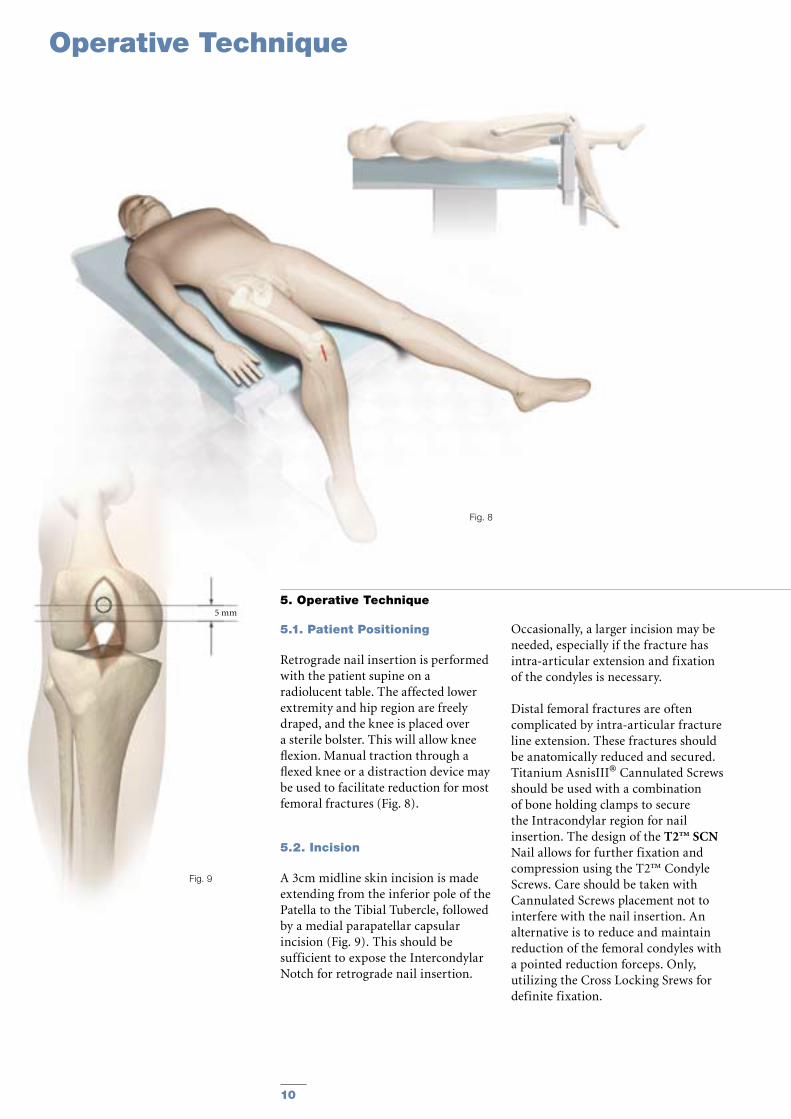
5. Operative Technique
5.1. Patient Positioning
Retrograde nail insertion is performed with the patient supine on a radiolucent table. The affected lower extremity and hip region are freely draped, and the knee is placed over a sterile bolster. This will allow knee flexion. Manual traction through a flexed knee or a distraction device may be used to facilitate reduction for most femoral fractures (Fig. 8).
5.2. Incision
A 3cm midline skin incision is made extending from the inferior pole of the Patella to the Tibial Tubercle, followed by a medial parapatellar capsular incision (Fig. 9). This should be sufficient to expose the Intercondylar Notch for retrograde nail insertion.
Fig. 9
Fig. 8
5 mm
Occasionally, a larger incision may be needed, especially if the fracture has intra-articular extension and fixation of the condyles is necessary.
Distal femoral fractures are often complicated by intra-articular fracture line extension. These fractures should be anatomically reduced and secured. Titanium AsnisIII® Cannulated Screws should be used with a combination of bone holding clamps to secure the Intracondylar region for nail insertion. The design of the T2™ SCN Nail allows for further fixation and compression using the T2™ Condyle Screws. Care should be taken with Cannulated Screws placement not to interfere with the nail insertion. An alternative is to reduce and maintain reduction of the femoral condyles with a pointed reduction forceps. Only, utilizing the Cross Locking Srews for definite fixation.
10 11
Fig. 10
Fig. 11a
Fig. 13Fig. 12
Fig. 11b
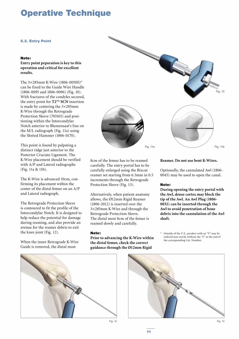
Note: Entry point peparation is key to this operation and critical for excellent results.
The 3×285mm K-Wire (1806-0050S)* can be fixed to the Guide Wire Handle (1806-0095 and 1806-0096) (Fig. 10). With fractures of the condyles secured, the entry point for T2™ SCN insertion is made by centering the 3×285mm K-Wire through the Retrograde Protection Sleeve (703165) and posi-tioning within the Intercondylar Notch anterior to Blumensaat‘s line on the M/L radiograph (Fig. 11a) using the Slotted Hammer (1806-0170).
This point is found by palpating a distinct ridge just anterior to the Posterior Cruciate Ligament. The K-Wire placement should be verified with A/P and Lateral radiographs (Fig. 11a & 11b).
The K-Wire is advanced 10cm, con-firming its placement within the center of the distal femur on an A/P and Lateral radiograph.
The Retrograde Protection Sleeve is contoured to fit the profile of the Intercondylar Notch. It is designed to help reduce the potential for damage during reaming, and also provide an avenue for the reamer debris to exit the knee joint (Fig. 12).
When the inner Retrograde K-Wire Guide is removed, the distal most
8cm of the femur has to be reamed carefully. The entry portal has to be carefully enlarged using the Bixcut reamer set starting from 6.5mm in 0.5 increments through the Retrograde Protection Sleeve (Fig. 13).
Alternatively, when patient anatomy allows, the Ø12mm Rigid Reamer (1806-2012) is inserted over the 3×285mm K-Wire and through the Retrograde Protection Sleeve. The distal most 8cm of the femur is reamed slowly and carefully.
Note: Prior to advancing the K-Wire within the distal femur, check the correct guidance through the Ø12mm Rigid
Reamer. Do not use bent K-Wires.
Optionally, the cannulated Awl (1806-0045) may be used to open the canal.
Note: During opening the entry portal with the Awl, dense cortex may block the tip of the Awl. An Awl Plug (1806-0032) can be inserted through the Awl to avoid penetration of bone debris into the cannulation of the Awl shaft.
* Outside of the U.S., product with an “S” may be ordered non-sterile without the “S” at the end of the corresponding Cat. Number.
Operative Technique
5.3. Entry Point

12 13
Operative Technique
Note: Fracture reduction should be per-formed prior to placement of the guide wire.
For the reamed technique, the 3×1000mm Ball Tip Guide Wire (1806-0085S)* is inserted through the fracture site and does not require a Guide Wire exchange. The Universal Rod with Reduction Spoon may be used as a fracture reduction tool to facilitate Guide Wire insertion through the fracture site (Fig. 14).
Note: The Ball Tip at the end of the Guide Wire will stop the reamer head and facilitate the removal of a broken reamer head.
Note: It is essential that all bone fragments are reduced prior to reaming.
Reaming (Fig. 15) of the femur should be performed very carefully and is commenced in 0.5mm increments until chatter or cortical contact is appreciated. Final reaming should be 1mm larger than the diameter of the nail to be inserted.
Note: If any provisional fixation screw used in reducing the fractures are in the line of the reamer they should be repositioned.
Note: Thoroughly irrigate the knee joint to remove any debris.
* Outside of the U.S., Locking Screws and other specif-ic products may be ordered non-sterile without the “S” at the end of the corresponding Cat. Number.
Fig. 15
Fig. 14
5.4. Reamed Technique
12 13
Fig. 17
Fig. 16
Effects of Cutting Flutes
Relative Area of Reamer
Typical StandardReamer Ø14mm
Clearance area =32% of cross section
Bixcut™Reamer Ø14mm
Clearance area=59% of cross section
Operative Technique
Bixcut™
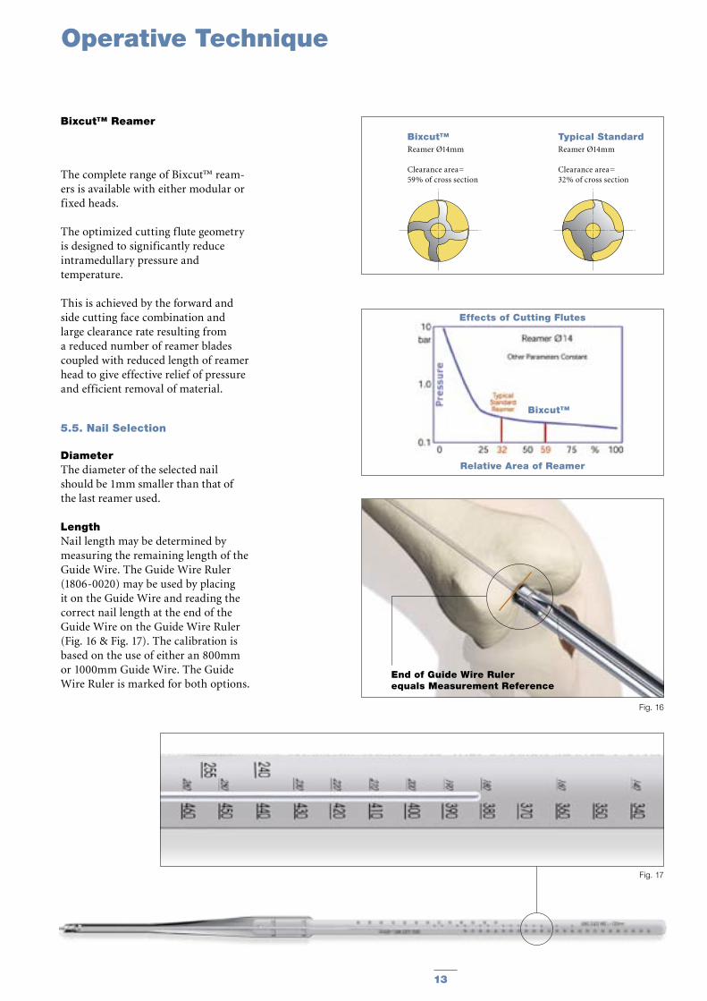
Bixcut™ Reamer
The complete range of Bixcut™ ream-ers is available with either modular or fixed heads.
The optimized cutting flute geometry is designed to significantly reduce intramedullary pressure and temperature.
This is achieved by the forward and side cutting face combination and large clearance rate resulting from a reduced number of reamer blades coupled with reduced length of reamer head to give effective relief of pressure and efficient removal of material.
5.5. Nail Selection
DiameterThe diameter of the selected nail should be 1mm smaller than that of the last reamer used.
LengthNail length may be determined by measuring the remaining length of the Guide Wire. The Guide Wire Ruler (1806-0020) may be used by placing it on the Guide Wire and reading the correct nail length at the end of the Guide Wire on the Guide Wire Ruler (Fig. 16 & Fig. 17). The calibration is based on the use of either an 800mm or 1000mm Guide Wire. The Guide Wire Ruler is marked for both options.
End of Guide Wire Ruler equals Measurement Reference

14 15
The selected nail is assembled onto the Nail Adapter (1806-3301) with the Nail Holding Screw, SCN (1806-3307) (Fig. 18).
Tighten the Nail Holding Screw with the Spanner 10mm (1806-0130) and the Spanner 12mm (1114-6004) acting as the counter force (Fig. 19).
For assembling the T2 SCN Short version follow the same instructions.
Note: Curvature of the nail must match the curvature of the femur.
The Slotted Hammer (1806-0170) can be used on the Nail Holding Screw (Fig. 20) or, if dense bone is encountered, the Universal Rod (1806-0110) may be attached to the Nail Holding Screw and used in con-junction with the Slotted Hammer to insert the nail.
Note: Only hit the Nail Holding Screw.
For repositioning the nail, the Univer-sal Rod and the Slotted Hammer may be attached to the Nail Holding Screw to carefully and smoothly extract the assembly.
Unique to the T2™ SCN System, the Guide Wire Ball Tip, 3×1000mm (1806-0085S) does not need to be exchanged.
Note: Remove the Guide Wire prior to drilling and inserting the locking screws.
When inserting the T2™ SCN, the nail should be counter-sunk below the Subchondral bone using Blumensaat‘s line as a reference (Fig. 21). The Nail Adapter has a marking at 10mm to allow for a reference with fluoroscopy.
Fig. 19
Step 2
Fig. 18
Fig. 20
Fig. 21
10mm
Step 1
The nail can never be left proud as this will destroy the Patella cartilage. Correct seating is verified with a lateral flouroscopic image with the condyles superimposed. The distal nail tip should be proximal to the subchondral line.
Operative Technique
5.6. Nail Insertion
14 15
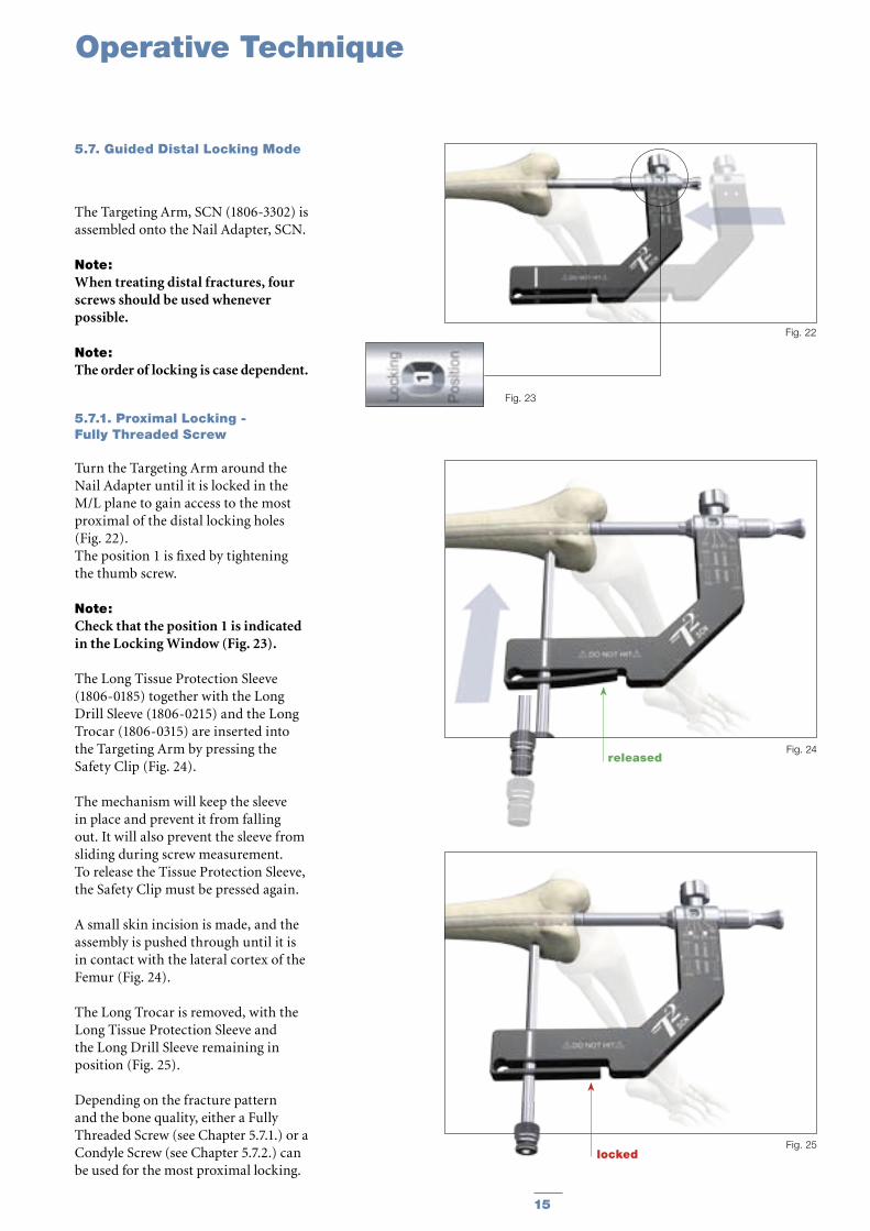
The Targeting Arm, SCN (1806-3302) is assembled onto the Nail Adapter, SCN.
Note: When treating distal fractures, four screws should be used whenever possible.
Note: The order of locking is case dependent.
5.7.1. Proximal Locking - Fully Threaded Screw
Turn the Targeting Arm around the Nail Adapter until it is locked in the M/L plane to gain access to the most proximal of the distal locking holes (Fig. 22).The position 1 is fixed by tightening the thumb screw.
Note:Check that the position 1 is indicated in the Locking Window (Fig. 23).
The Long Tissue Protection Sleeve (1806-0185) together with the Long Drill Sleeve (1806-0215) and the Long Trocar (1806-0315) are inserted into the Targeting Arm by pressing the Safety Clip (Fig. 24).
The mechanism will keep the sleeve in place and prevent it from falling out. It will also prevent the sleeve from sliding during screw measurement. To release the Tissue Protection Sleeve, the Safety Clip must be pressed again.
A small skin incision is made, and the assembly is pushed through until it is in contact with the lateral cortex of the Femur (Fig. 24).
The Long Trocar is removed, with the Long Tissue Protection Sleeve and the Long Drill Sleeve remaining in position (Fig. 25).
Depending on the fracture pattern and the bone quality, either a Fully Threaded Screw (see Chapter 5.7.1.) or a Condyle Screw (see Chapter 5.7.2.) can be used for the most proximal locking.
Fig. 22
Fig. 23
Fig. 25locked
Fig. 24released
Operative Technique
5.7. Guided Distal Locking Mode
16 17
Operative Technique
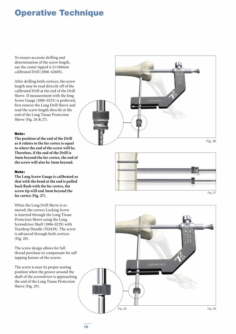
To ensure accurate drilling and determination of the screw length, use the center tipped 4.2×340mm calibrated Drill (1806-4260S).
After drilling both cortices, the screw length may be read directly off of the calibrated Drill at the end of the Drill Sleeve. If measurement with the long Screw Gauge (1806-0325) is preferred, first remove the Long Drill Sleeve and read the screw length directly at the end of the Long Tissue Protection Sleeve (Fig. 26 & 27).
Note: The position of the end of the Drill as it relates to the far cortex is equal to where the end of the screw will be. Therefore, if the end of the Drill is 3mm beyond the far cortex, the end of the screw will also be 3mm beyond.
Note: The Long Screw Gauge is calibrated so that with the bend at the end is pulled back flush with the far cortex, the screw tip will end 3mm beyond the far cortex (Fig. 27).
When the Long Drill Sleeve is re-moved, the correct Locking Screw is inserted through the Long Tissue Protection Sleeve using the Long Screwdriver Shaft (1806-0229) with Teardrop Handle (702429). The screw is advanced through both cortices (Fig. 28).
The screw design allows for full thread purchase to compensate for self tapping feature of the screws.
The screw is near its proper seating position when the groove around the shaft of the screwdriver is approaching the end of the Long Tissue Protection Sleeve (Fig. 29).
Fig. 26
Fig. 27
Fig. 28Fig. 29
16 17
Fig. 33
Fig. 30
Fig. 31
Fig. 32
Fig. 30a
Condyle Screw-introduced M-L
Condyle Screw-introduced L-M
Operative Technique
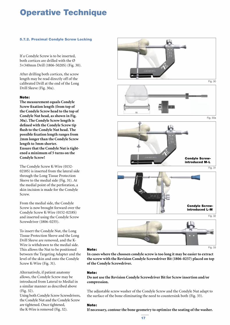
If a Condyle Screw is to be inserted, both cortices are drilled with the Ø 5×340mm Drill (1806-5020S) (Fig. 30).
After drilling both cortices, the screw length may be read directly off of the calibrated Drill at the end of the Long Drill Sleeve (Fig. 30a).
Note: The measurement equals Condyle Screw fixation length (from top of the Condyle Screw head to the top of Condyle Nut head, as shown in Fig. 30a). The Condyle Screw length is defined with the Condyle Screw tip flush to the Condyle Nut head. The possible fixation length ranges from 2mm longer than the Condyle Screw length to 5mm shorter.Ensure that the Condyle Nut is tight-ened a minimum of 5 turns on the Condyle Screw!
The Condyle Screw K-Wire (0152-0218S) is inserted from the lateral side through the Long Tissue Protection Sleeve to the medial side (Fig. 31). At the medial point of the perforation, a skin incision is made for the Condyle Screw.
From the medial side, the Condyle Screw is now brought forward over the Condyle Screw K-Wire (0152-0218S) and inserted using the Condyle Screw Screwdriver (1806-0255).
To insert the Condyle Nut, the Long Tissue Protection Sleeve and the Long Drill Sleeve are removed, and the K-Wire is withdrawn to the medial side. This allows the Nut to be positioned between the Targeting Adapter and the level of the skin and onto the Condyle Screw K-Wire (Fig. 31).
Alternatively, if patient anatomy allows, the Condyle Screw may be introduced from Lateral to Medial in a similar manner as described above (Fig. 32).Using both Condyle Screw Screwdrivers, the Condyle Nut and the Condyle Screw are tightened. Once tightened, the K-Wire is removed (Fig. 32).
Note: In cases where the choosen condyle screw is too long it may be easier to extract the screw with the Revision Condyle Screwdriver Bit (1806-0257) placed on top of the Condyle Screwdriver.
Note: Do not use the Revision Condyle Screwdriver Bit for Screw insertion and/or compression.
The adjustable screw washer of the Condyle Screw and the Condyle Nut adapt to the surface of the bone eliminating the need to countersink both (Fig. 33).
Note: If necessary, contour the bone geometry to optimize the seating of the washer.
5.7.2. Proximal Condyle Screw Locking

18 19
Operative Technique
Turn and pull back the Targeting Arm around the Nail Adapter until the system is locked in the oblique plane to gain access to the most proximal oblique locking hole. The position is fixed by tightening the thumb screw.
Note: Check that position 2 is indicated in the Locking Window (Fig. 34).
The Long Tissue Protection Sleeve (together with the Long Drill Sleeve and the Long Trocar) is inserted into the Targeting Arm by pressing the Safety Clip. To release the Tissue Protection Sleeve, the Safety Clip must be pressed again.
A small skin incision is made, and the assembly is pushed through until it is in contact with the cortex of the Femur. The Long Trocar is removed, with the Long Tissue Protection Sleeve and the Long Drill Sleeve remaining in position.
To ensure accurate drilling and easy determination of the screw length, use the center tipped 4.2×340mm calibrated Drill (1806-4260S). The centered Drill is forwarded through the Drill Sleeve and pushed onto the cortex (Fig. 35). After drilling both cortices, the screw length may be read directly off of the calibrated Drill at the end of the Drill Sleeve. If measurement with the Long Screw Gauge (1806-0325) is preferred, first remove the Long Drill Sleeve and read the screw length directly at the end of the Long Tissue Protection Sleeve (Fig. 27, page 16).
Note: The position of the end of the Drill as it relates to the far cortex is equal to where the end of the screw will be. Therefore, if the end of the Drill is 3mm beyond the far cortex, the end of the screw will also be 3mm beyond.
When the Long Drill Sleeve is removed, the correct Locking Screw is
Fig. 34
Fig. 35
Fig. 36
inserted through the Long Tissue Protection Sleeve using the Long Screwdriver Shaft with Teardrop Handle. The screw is advanced through both corticies (Fig. 36). The screw is near its proper seating position when the groove around the shaft of the screwdriver is approaching the end of the Long Tissue Protection Sleeve.
5.7.3. Oblique Screw Locking
18 19
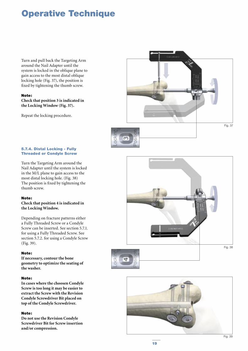
5.7.4. Distal Locking - Fully Threaded or Condyle Screw
Turn the Targeting Arm around the Nail Adapter until the system is locked in the M/L plane to gain access to the most distal locking hole. (Fig. 38)The position is fixed by tightening the thumb screw.
Note: Check that position 4 is indicated in the Locking Window.
Depending on fracture patterns either a Fully Threaded Screw or a Condyle Screw can be inserted. See section 5.7.1. for using a Fully Threaded Screw. See section 5.7.2. for using a Condyle Screw (Fig. 39).
Note: If necessary, contour the bone geometry to optimize the seating of the washer.
Note: In cases where the choosen Condyle Screw is too long it may be easier to extract the Screw with the Revision Condyle Screwdriver Bit placed on top of the Condyle Screwdriver.
Note: Do not use the Revision Condyle Screwdriver Bit for Screw insertion and/or compression.
Fig. 38
Fig. 39
Operative Technique
Fig. 37
Turn and pull back the Targeting Arm around the Nail Adapter until the system is locked in the oblique plane to gain access to the most distal oblique locking hole (Fig. 37), the position is fixed by tightening the thumb screw.
Note: Check that position 3 is indicated in the Locking Window (Fig. 37).
Repeat the locking procedure.
20 21
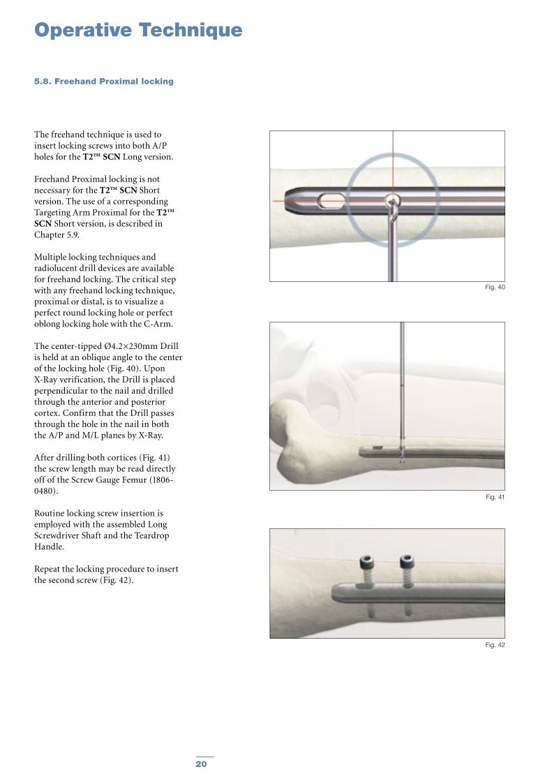
The freehand technique is used to insert locking screws into both A/P holes for the T2™ SCN Long version.
Freehand Proximal locking is not necessary for the T2™ SCN Short version. The use of a corresponding Targeting Arm Proximal for the T2™ SCN Short version, is described in Chapter 5.9.
Multiple locking techniques and radiolucent drill devices are available for freehand locking. The critical step with any freehand locking technique, proximal or distal, is to visualize a perfect round locking hole or perfect oblong locking hole with the C-Arm.
The center-tipped Ø4.2×230mm Drill is held at an oblique angle to the center of the locking hole (Fig. 40). Upon X-Ray verification, the Drill is placed perpendicular to the nail and drilled through the anterior and posterior cortex. Confirm that the Drill passes through the hole in the nail in both the A/P and M/L planes by X-Ray.
After drilling both cortices (Fig. 41) the screw length may be read directly off of the Screw Gauge Femur (1806-0480).
Routine locking screw insertion is employed with the assembled Long Screwdriver Shaft and the Teardrop Handle.
Repeat the locking procedure to insert the second screw (Fig. 42).
Fig. 40
Fig. 41
Fig. 42
Operative Technique
5.8. Freehand Proximal locking

20 21
Fig. 46
Fig. 47
Fig. 44
Fig. 45
Operative Technique
Fig. 43
Remove the Targeting Arm, SCN and assemble the Targeting Arm Proximal, SCN onto the Nail Adapter (Fig. 43).
Note: The Targeting Arm Proximal, SCN must be locked in position 1.
The Targeting Arm Proximal, SCN is designed to provide guided proximal locking for the T2™ SCN Short version 170 and 200mm.
Note: A load on the Targeting Arm Proximal, SCN may lead to a deflection of the Arm which will have a negative influence during the drilling procedure.
The Long Tissue Protection Sleeve together with the Long Drill Sleeve and the Long Trocar are inserted into the corresponding hole of the Targeting Arm for the selected nail (Fig. 44).
Routine drilling and the locking procedure are employed for the Proximal locking (Fig. 44−47).
5.9. Guided Proximal Locking T2™ SCN Short version
22 23
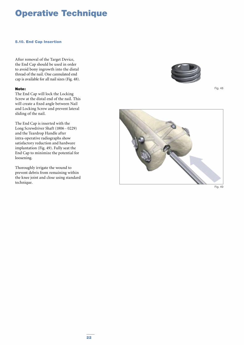
After removal of the Target Device, the End Cap should be used in order to avoid bony ingrowth into the distal thread of the nail. One cannulated end cap is available for all nail sizes (Fig. 48).
Note: The End Cap will lock the Locking Screw at the distal end of the nail. This will create a fixed angle between Nail and Locking Screw and prevent lateral sliding of the nail.
The End Cap is inserted with the Long Screwdriver Shaft (1806 - 0229) and the Teardrop Handle after intra-operative radiographs show satisfactory reduction and hardware implantation (Fig. 49). Fully seat the End Cap to minimize the potential for loosening.
Thoroughly irrigate the wound to prevent debris from remaining within the knee joint and close using standard technique.
Fig. 49
Fig. 48
Operative Technique
5.10. End Cap Insertion
22 23
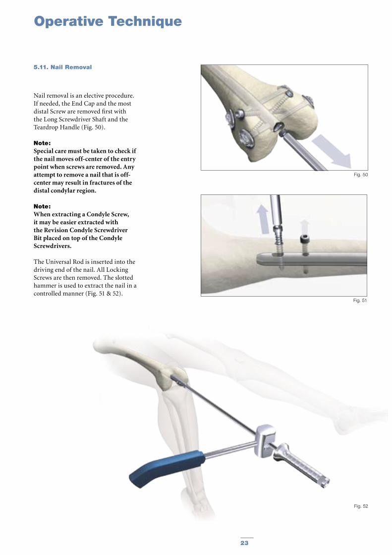
Nail removal is an elective procedure. If needed, the End Cap and the most distal Screw are removed first with the Long Screwdriver Shaft and the Teardrop Handle (Fig. 50).
Note: Special care must be taken to check if the nail moves off-center of the entry point when screws are removed. Any attempt to remove a nail that is off-center may result in fractures of the distal condylar region.
Note: When extracting a Condyle Screw, it may be easier extracted with the Revision Condyle Screwdriver Bit placed on top of the Condyle Screwdrivers.
The Universal Rod is inserted into the driving end of the nail. All Locking Screws are then removed. The slotted hammer is used to extract the nail in a controlled manner (Fig. 51 & 52).
Fig. 52
Fig. 51
Fig. 50
Operative Technique
5.11. Nail Removal
24 25
Ordering Information - Implants
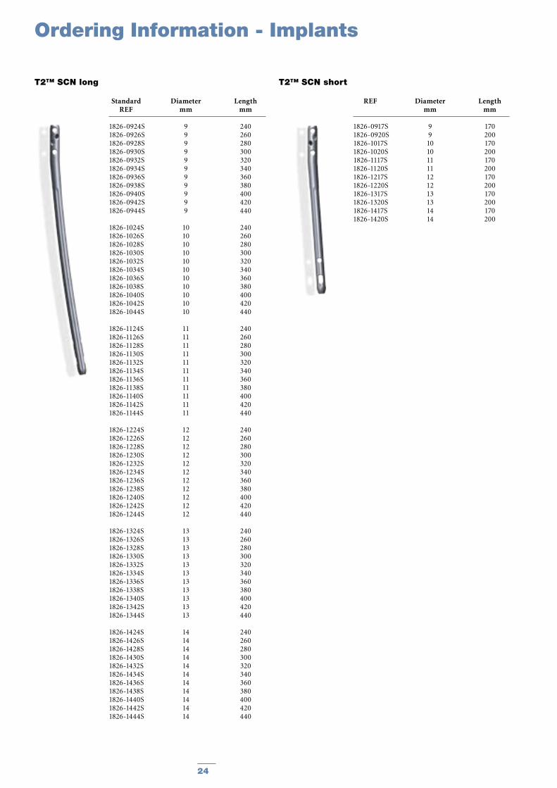
T2™ SCN short
REF Diameter Length mm mm
1826-0917S 9 170 1826-0920S 9 200 1826-1017S 10 170 1826-1020S 10 200 1826-1117S 11 170 1826-1120S 11 200 1826-1217S 12 170 1826-1220S 12 200 1826-1317S 13 170 1826-1320S 13 200 1826-1417S 14 170 1826-1420S 14 200
T2™ SCN long
Standard Diameter Length REF mm mm
1826-0924S 9 240 1826-0926S 9 260 1826-0928S 9 280 1826-0930S 9 300 1826-0932S 9 320 1826-0934S 9 340 1826-0936S 9 360 1826-0938S 9 380 1826-0940S 9 400 1826-0942S 9 420 1826-0944S 9 440
1826-1024S 10 240 1826-1026S 10 260 1826-1028S 10 280 1826-1030S 10 300 1826-1032S 10 320 1826-1034S 10 340 1826-1036S 10 360 1826-1038S 10 380 1826-1040S 10 400 1826-1042S 10 420 1826-1044S 10 440
1826-1124S 11 240 1826-1126S 11 260 1826-1128S 11 280 1826-1130S 11 300 1826-1132S 11 320 1826-1134S 11 340 1826-1136S 11 360 1826-1138S 11 380 1826-1140S 11 400 1826-1142S 11 420 1826-1144S 11 440
1826-1224S 12 240 1826-1226S 12 260 1826-1228S 12 280 1826-1230S 12 300 1826-1232S 12 320 1826-1234S 12 340 1826-1236S 12 360 1826-1238S 12 380 1826-1240S 12 400 1826-1242S 12 420 1826-1244S 12 440
1826-1324S 13 240 1826-1326S 13 260 1826-1328S 13 280 1826-1330S 13 300 1826-1332S 13 320 1826-1334S 13 340 1826-1336S 13 360 1826-1338S 13 380 1826-1340S 13 400 1826-1342S 13 420 1826-1344S 13 440
1826-1424S 14 240 1826-1426S 14 260 1826-1428S 14 280 1826-1430S 14 300 1826-1432S 14 320 1826-1434S 14 340 1826-1436S 14 360 1826-1438S 14 380 1826-1440S 14 400 1826-1442S 14 420 1826-1444S 14 440
24 25
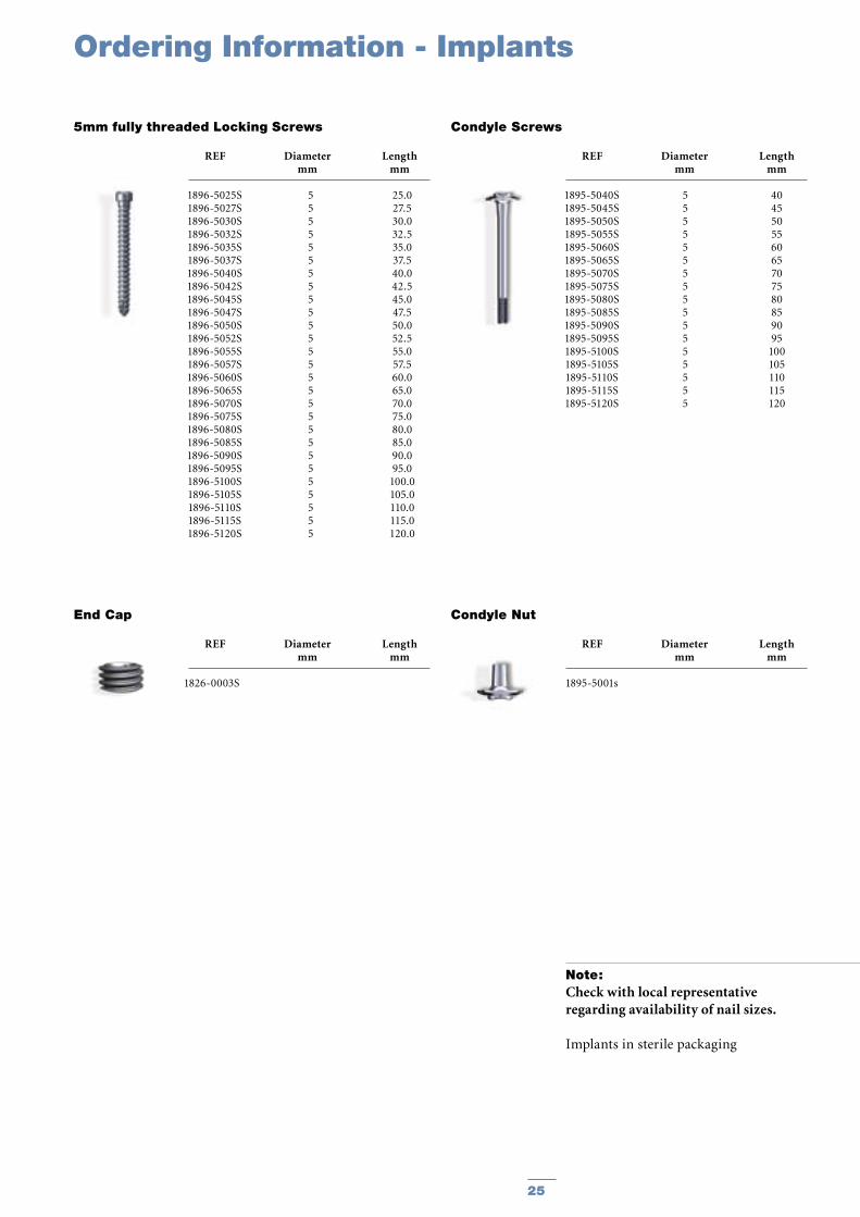
1896-5025S1896-5027S1896-5030S1896-5032S1896-5035S1896-5037S1896-5040S1896-5042S1896-5045S1896-5047S1896-5050S1896-5052S1896-5055S1896-5057S1896-5060S1896-5065S1896-5070S1896-5075S1896-5080S1896-5085S1896-5090S1896-5095S1896-5100S1896-5105S1896-5110S1896-5115S1896-5120S
5 25.05 27.55 30.05 32.55 35.0 5 37.5 5 40.0 5 42.55 45.05 47.55 50.0 5 52.55 55.0 5 57.55 60.05 65.05 70.05 75.05 80.05 85.05 90.05 95.05 100.05 105.05 110.05 115.05 120.0
1826-0003S
End Cap
REF Diameter Length mm mm
Ordering Information - Implants
REF Diameter Length mm mm
1826-0917S 9 170 1826-0920S 9 200 1826-1017S 10 170 1826-1020S 10 200 1826-1117S 11 170 1826-1120S 11 200 1826-1217S 12 170 1826-1220S 12 200 1826-1317S 13 170 1826-1320S 13 200 1826-1417S 14 170 1826-1420S 14 200
Note: Check with local representative regarding availability of nail sizes.
Implants in sterile packaging
5mm fully threaded Locking Screws
REF Diameter Length mm mm
1895-5040S1895-5045S1895-5050S1895-5055S1895-5060S1895-5065S1895-5070S1895-5075S1895-5080S1895-5085S1895-5090S1895-5095S1895-5100S1895-5105S1895-5110S1895-5115S1895-5120S
5 405 455 505 555 605 655 705 755 805 855 905 955 1005 1055 1105 1155 120
Condyle Screws
REF Diameter Length mm mm
1895-5001s
Condyle Nut
REF Diameter Length mm mm

26 2726
Ordering Information - Instruments
REF Description
Standard Instruments
0152-0218 K-Wire, Ø1.8×310mm (2×)
1806-0045 Awl, Straight
1806-0095 Guide Wire Handle
1806-0096 Guide Wire Handle Chuck
1114-6004 Spanner, SW 12
1806-2012 Rigid Reamer, Ø12mm
1806-0020 Guide Wire Ruler
1806-0050 K-Wire Ø3×285mm (2×)
1806-0110 Universal Rod
1806-0125 Reduction Spoon
1806-0130 Wrench, 8mm/10mm
1806-0170 Slotted Hammer
1806-0185 Tissue Protection Sleeve, Long
1806-0215 Drill Sleeve, Long
1806-0229 Screwdriver Shaft AO, Long
1806-0232 Screwdriver, Long
1806-0255 Screwdriver, Condyle Screw (2×)
1806-0257 Revision Condyle Screwdriver Bit
1806-0294 Screw Driver Shaft, 3.5×85mm
1806-0315 Trocar, Long
1806-0325 Screw Gauge, Long
1806-0350 Extraction Rod, Conical, 8mm
1806-0480 Screw Gauge, Femur
702429 Teardrop Handle, AO
703165 Protection Sleeve Retrograde
1806-3000 Target Device SCN, complete (Nail Adapter, Targeting Arm, Targeting Arm Proximal)
1806-3301 Nail Adapter, SCN
1806-3302 Targeting Arm, SCN
1806-3305 Targeting Arm Proximal, SCN
1806-3307 Nail Holding Screw, SCN
1806-3306 X-Ray Template, SCN
1806-4260 Drill Ø4.2×340mm, AO (2×)
1806-4270 Drill Ø4.2×180mm, AO (2×)
1806-5020 Drill Ø5.0×340mm, AO (2×)
1806-9200 Instrument Tray SCN
1806-9210 Add-on Instrument Tray SCN
* Instruments designated “Outside of the U.S.” may not be ordered for the U.S. market.
REF Description
Optional Instruments
1806-0032 Awl Plug
1806-4260S Drill Ø4.2×340mm, AO (2×)
1806-4270S Drill Ø4.2×180mm, AO (2×)
1806-5020S Drill Ø5.0×340mm, AO (2×)
26 27
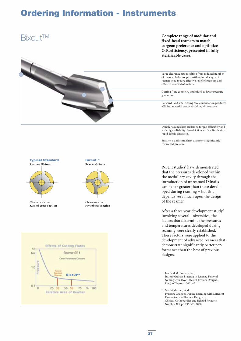
Complete range of modular and fixed-head reamers to match surgeon preference and optimize O. R. efficiency, presented in fully sterilizable cases.
Recent studies1 have demonstrated that the pressures developed within the medullary cavity through the introduction of unreamed IMnails can be far greater than those devel-oped during reaming − but this depends very much upon the design of the reamer.
After a three year development study2 involving several universities, the factors that determine the pressures and temperatures developed during reaming were clearly established. These factors were applied to the development of advanced reamers that demonstrate significantly better per-formance than the best of previous designs.
1 Jan Paul M. Frolke, et al. ; Intramedullary Pressure in Reamed Femoral
Nailing with Two Different Reamer Designs., Eur. J. of Trauma, 2001 #5
2 Medhi Massau, et al.; Pressure Changes During Reaming with Different
Parameters and Reamer Designs, Clinical Orthopaedics and Related Research
Number 373, pp. 295-303, 2000
Large clearance rate resulting from reduced number of reamer blades coupled with reduced length of reamer head to give effective relief of pressure and efficient removal of material.
Cutting f lute geometry optimized to lower pressure generation.
Forward- and side-cutting face combination produces efficient material removal and rapid clearance.
Double-wound shaft transmits torque effectively and with high reliability. Low-friction surface finish aids rapid debris clearance.
Smaller, 6 and 8mm shaft diameters significantly reduce IM pressure.
Typical StandardReamer Ø14mm
Clearance area :32% of cross section
Bixcut™Reamer Ø14mm
Clearance area :59% of cross section
Bixcut™
Bixcut™
Ordering Information - Instruments
28 29
0226-30900226-30950226-31000226-31050226-31100226-31150226-31200226-31250226-31300226-31350226-31400226-31450226-31500226-31550226-31600226-31650226-31700226-31750226-31800226-41850226-41900226-41950226-42000226-42050226-42100226-42150226-42200226-42250226-42300226-42350226-42400226-42450226-42500226-42550226-42600226-42650226-42700226-42750226-4280
9.09.5
10.010.511.011.512.012.513.013.514.014.515.015.516.016.517.017.518.018.519.019.520.020.521.021.522.022.523.023.524.024.525.025.526.026.527.027.528.0
Bixcut HeadBixcut HeadBixcut HeadBixcut HeadBixcut HeadBixcut HeadBixcut HeadBixcut HeadBixcut HeadBixcut HeadBixcut HeadBixcut HeadBixcut HeadBixcut HeadBixcut HeadBixcut HeadBixcut HeadBixcut HeadBixcut HeadBixcut HeadBixcut HeadBixcut HeadBixcut HeadBixcut HeadBixcut HeadBixcut HeadBixcut HeadBixcut HeadBixcut HeadBixcut HeadBixcut HeadBixcut HeadBixcut HeadBixcut HeadBixcut HeadBixcut HeadBixcut HeadBixcut HeadBixcut Head
0226-30000226-8240
Shaft, AOShaft, AO
450240
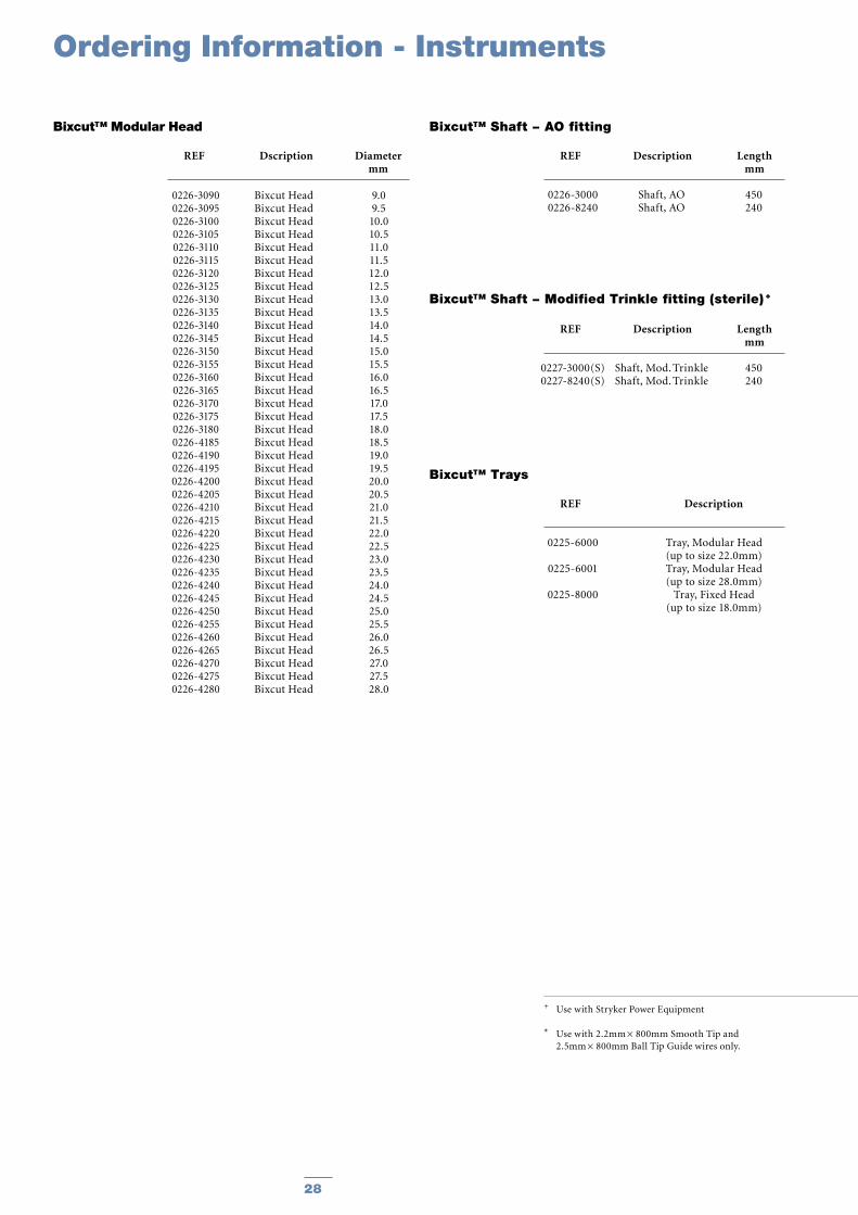
+ Use with Stryker Power Equipment
* Use with 2.2mm × 800mm Smooth Tip and 2.5mm × 800mm Ball Tip Guide wires only.
Ordering Information - Instruments
Bixcut™ Shaft − AO fitting
REF Description Length mm
Bixcut™ Modular Head
REF Dscription Diameter mm
0225-6000
0225-6001
0225-8000
Tray, Modular Head(up to size 22.0mm)Tray, Modular Head(up to size 28.0mm)
Tray, Fixed Head(up to size 18.0mm)
Bixcut™ Trays
REF Description
0227-3000(S)0227-8240(S)
Shaft, Mod. TrinkleShaft, Mod. Trinkle
450240
Bixcut™ Shaft − Modified Trinkle fitting (sterile) +
REF Description Length mm
28 29
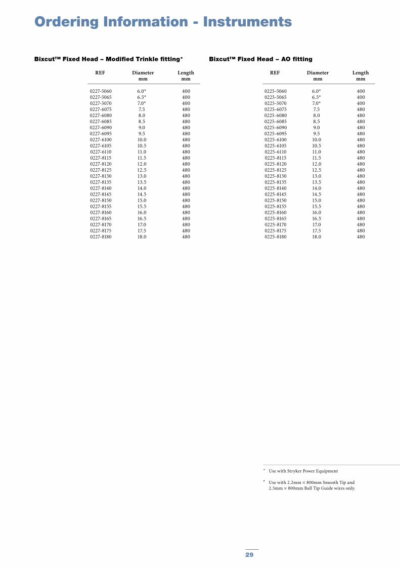
+ Use with Stryker Power Equipment
* Use with 2.2mm × 800mm Smooth Tip and 2.5mm × 800mm Ball Tip Guide wires only.
REF Description Length mm
REF Description
REF Description Length mm
0227-50600227-50650227-50700227-60750227-60800227-60850227-60900227-60950227-61000227-61050227-61100227-81150227-81200227-81250227-81300227-81350227-81400227-81450227-81500227-81550227-81600227-81650227-81700227-81750227-8180
400400400480480480480480480480480480480480480480480480480480480480480480480
6.0*6.5*7.0*7.58.08.59.09.5
10.010.511.011.512.012.513.013.514.014.515.015.516.016.517.017.518.0
Bixcut™ Fixed Head − Modified Trinkle fitting+
REF Diameter Length mm mm
0225-50600225-50650225-50700225-60750225-60800225-60850225-60900225-60950225-61000225-61050225-61100225-81150225-81200225-81250225-81300225-81350225-81400225-81450225-81500225-81550225-81600225-81650225-81700225-81750225-8180
400400400480480480480480480480480480480480480480480480480480480480480480480
6.0*6.5*7.0*7.58.08.59.09.5
10.010.511.011.512.012.513.013.514.014.515.015.516.016.517.017.518.0
Bixcut™ Fixed Head − AO fitting
REF Diameter Length mm mm
Ordering Information - Instruments

30 31
Notes

30 31
Notes

Joint Replacements
Trauma
Spine
Micro Implants
Orthobiologics
Instruments
Interventional Pain
Navigation
Endoscopy
Communications
Patient Handling Equipment
EMS Equipment
Prof.-Küntscher-Strasse 1-5D-24232 SchönkirchenGermany
www.trauma.stryker.com
The information presented in this brochure is intended to demonstrate a Stryker product. Always refer to the package insert, product label and/or user instructions before using any Stryker product. Products may not be available in all markets. Product availability is subject to the regulatory or medical practices that govern individual markets. Please contact your Stryker representative if you have questions about the availability of Stryker products in your area.
Products referenced with ™ designation are trademarks of Stryker. Products referenced with ® designation are registered trademarks of Stryker.
REF NO. B1000020LOT B1904
Copyright © 2004 StrykerPrinted in Germany