Embed Size (px)
Citation preview

Solutions To : Tutorial 2 Q1
(a)
For the straight strip of the above dimensions,
4943333 m10512
1m1051040
12
1
12
1 bhI z
Pa10210GPa210 9E
Now, recall that R
EIM z
xz , yI
My
I
My
R
E
z
xzxx
Since m5.2R ,
MPa210Pa10210m5.2
m105.2Pa10210
Nm0.35m5.2
m10512
1Pa10210
639
max
499
xx
xx
zxz
yR
E
R
EIM
y
z
40 mm
5 mm

(b) If the stress is not to exceed 300 MPa,
m75.1
Pa10300
m105.2Pa10210
Pa10300m105.2Pa10210
Pa10300
6
39
639
6
max
R
R
yR
Exx
Hence, the smallest diameter the cask can have if the stress is not to exceed
300 MPa is 3.5 m.
(c) If the material of the strip is brass instead of steel, then
MPa100Pa10100m5.2
m105.2Pa10100
Nm67.16m5.2
m10512
1Pa10100
639
max
499
xx
xx
zxz
yR
E
R
EIM
(d) If the hoop is split at a point by sawing through it, what will its final
shape be?
Straight (elastic unloading).

Solutions To : Tutorial 2 Q2
47
4343
44
m105.664
1020103064
64
dDI z
Since the weight of the national service man is N81.960 , the loading on
the tubular aluminium bar is:
Using singularity functions,
1111
0000
1111
4.13.2941.13.2943.03.2943.294
4.13.2941.13.2943.03.2943.294
4.13.2941.13.2943.03.2943.294
xxxxxM
xxxxxF
xxxxxq
xz
xy
0.3 m 0.3 m 0.8 m
0.3 m 0.3 m 0.8 m
d = 20 mm
D = 30 mm

Since 11114.13.2941.13.2943.03.2943.294 xxxxxM xz
Hence, we have
m4.1m1.1Nm4.13.294
m1.1m3.0Nm29.88
m3.0m0.0Nm3.294
m4.1m1.1Nm4.13.294
m1.1m3.0Nm3.03.294
m3.0m0.0Nm3.294
m4.1m1.1Nm1.13.2943.03.2943.294
m1.1m3.0Nm3.03.2943.294
m3.0m0.0Nm3.294
xx
x
xx
xx
x
xx
xxxx
xxx
xx
xM xz
The bending moment diagram:
(a) Now, recall that yI
M
z
xzxx
, thus
2
max
max
D
I
M
z
xz
xx
MPa5.41Pa10506.41
2
m1030
m105.664
Nm29.88 63
47max
xx
Hence the maximum stress induced in the bar is 41.5 MPa.
Mxz
x
88.29Nm
0.3 1.1 1.4 0.0

To calculate the maximum shear stress:
Shear force,
Shear stress,
We have:
( )
(
)
( )
( )
Hence,
(b) The portion of the bar between his hands will deflect into a circular
shape (because bending moment is constant).
(c) If the National Serviceman releases one arm and continues to do
single-arm chin-ups, the loading on the tubular bar becomes:
1.1 m 0.3 m
R1 = 126.1 N R2 = 462.5 N

Taking moments,
01.181.9604.1
03.081.9604.1
2
1
R
R
N5.462N6.5884.1
1.1
N1.126N6.5884.1
3.0
2
1
R
R
Using singularity functions,
111
000
111
4.15.4621.16.5881.126
4.15.4621.16.5881.126
4.15.4621.16.5881.126
xxxxM
xxxxF
xxxxq
xz
xy
Since 1114.15.4621.16.5881.126 xxxxM xz
Hence, we have
m4.1m1.1Nm5.46246.647
m1.1m0.0Nm1.126
m4.1m1.1Nm1.16.5881.126
m1.1m0.0Nm1.126
xx
xx
xxx
xxxM xz
The bending moment diagram:
Mxz
x
138.71Nm
1.1 1.4 0.0
Now, recall that yI
M
z
xzxx
, thus
2
max
max
D
I
M
z
xz
xx
MPa2.65Pa10210.65
2
m1030
m105.664
Nm71.138 63
47max
xx
Hence the maximum stress induced in the bar is increased to 65.2
MPa. (An increment of %1.57%1005.41
5.412.65
.)
To calculate the maximum shear stress:
Shear force (obtained from vertical equilibrium),
Hence,
Maximum shear stress increases by 57% to 2.27 N/mm
2
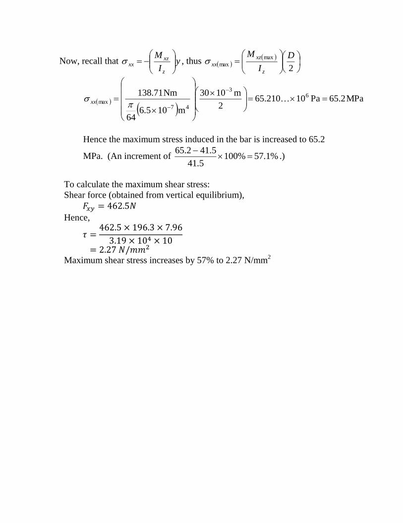
Solutions To : Tutorial 2 Q3
Since beam AC is simply-supported, and
is loaded by a concentrated bending
moment of 50 kNm at B, we have:
Taking moments,
010500.3
010500.33
2
31
R
R
kN3
50N
3
1050
kN3
50N
3
1050
3
2
3
1
R
R
75 75
200
50
125
A B
C
2000 mm 1000 mm
50 kNm
A B
C
2.0 m 1.0 m
50 kNm
R1 R2
A B
C
2.0 m 1.0 m
50 kNm

Using singularity functions,
130313
031303
132313
3103
502105010
3
50
3103
502105010
3
50
3103
502105010
3
50
xxxxM
xxxxF
xxxxq
xz
xy
Since 130313 3103
502105010
3
50 xxxxM xz
Hence, we have
m0.3m0.2Nm1050103
50
m0.2m0.0Nm103
50
33
3
xx
xxxM xz
The bending moment diagram:
Mxz
x
kNm
2.0 0.0 3.0
kNm
A B
C
2.0 m 1.0 m
50 kNm

To determine the values and
locations of the maximum
tensile and compressive stresses
in the beam, we need to first
locate the position of the
centroid y of the given cross-
section.
221
222
221
mm16250
mm10000mm50200
mm6250mm12550
AA
A
A
To determine y , we have
mm7.58
mm65384615.58
16250
25100005.1126250
255.112
252
12550
21
21
2121
AA
AAy
yAAAA
75 75
200
50
125
75 75
200
50
125
A2
A1

46
4126464
4
42323
4232
3
m107.39
m10107.39mm107.39mm17.39668504
mm1135690012
2500000018090250
12
97656250
mm7.33502005020012
18.531255012550
12
1
mm257.58502005020012
17.58
2
125501255012550
12
1
zI
Consider the beam to the left of B (where the bending moment is negative)
Hence, evidently the top fibres are in tension
and the bottom fibres are in compression.
Using yI
M
z
xzxx
yy
I
M
xx
z
xz3
46
3
46
max
Nm5.839630562m107.39
Nm103
100
m107.39
kNm3
100
For the top fibre, m0587.0mm7.58 y ,
58.7
z
y
ve bending moment

tensileMPa3.49
Nm02.49286314m0587.0Nm5.839630562 23
xx
For the bottom fibre, m1163.0mm3.116 y ,
ecompressivMPa6.97
Nm42.97649034m1163.0Nm5.839630562 23
xx
Consider the beam to the right of B (where the bending moment is positive)
Hence, evidently the top fibres are in
compression and the bottom fibres are in tension.
Using yI
M
z
xzxx
yy
I
M
xx
z
xz3
46
3
46
max
Nm3.419815281m107.39
Nm103
50
m107.39
kNm3
50
For the top fibre, m0587.0mm7.58 y ,
ecompressivMPa6.24
Nm01.24643157m0587.0Nm3.419815281 23
xx
For the bottom fibre, m1163.0mm3.116 y ,
tensileMPa8.48
Nm22.48824517m1163.0Nm3.419815281 23
xx
Hence, the maximum tensile stress is 49.3 MPa at the top fibre left of B and
the maximum compressive stress is –97.0 MPa at the bottom fibre left of B.
Alternatively, depending on accuracy, your answer may be:
Maximum tensile stress is 49 MPa at the top fibre left of B or at the bottom
fibre right of B.
+ve bending moment

To calculate the maximum shear stress:
Shear force,
We have:
Shear stress,
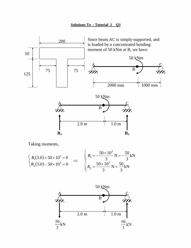
Solutions To : Tutorial 2 Q4
From symmetry, it is evident
that 2
21
PRR
Due to symmetry, we only
need to perform analysis of
the stress at points B and C.
We can discard point A since
it is a free end and the bending
moment xzM is zero ( stress
due to bending is zero at A).
Bending moments:
At B, Nm10
110
PPM xz
At C, Nm10
31
22
10
PPPM xz
1 m 1 m 1 m 1 m
A B C D E
X
X
0.075 0.075
0.050
0.125
0.050
A B C D E
R1 = R2 =

To determine the values and
locations of the maximum tensile and
compressive stresses in the beam, we
need to first locate the position of the
centroid y of the given cross-
section.
221
222
221
m01625.0
m010.0m050.0200.0
m00625.0m125.0050.0
AA
A
A
To determine y , we have
m0587.0
m50586538461.0
01625.0
025.0010.01125.000625.0
025.01125.0
025.02
125.0050.0
21
21
2121
AA
AAy
yAAAA
0.075 0.075
0.050
0.125
0.050
A1
A2
0.0587
z
y
4545
4
23
23
4
23
23
m1097.3m10966850417.3
m
0337.0050.0200.0050.0200.012
1
0538.0125.0050.0125.0050.012
1
m
025.00587.0050.0200.0050.0200.012
1
0587.02
125.0050.0125.0050.0125.0050.0
12
1
zI
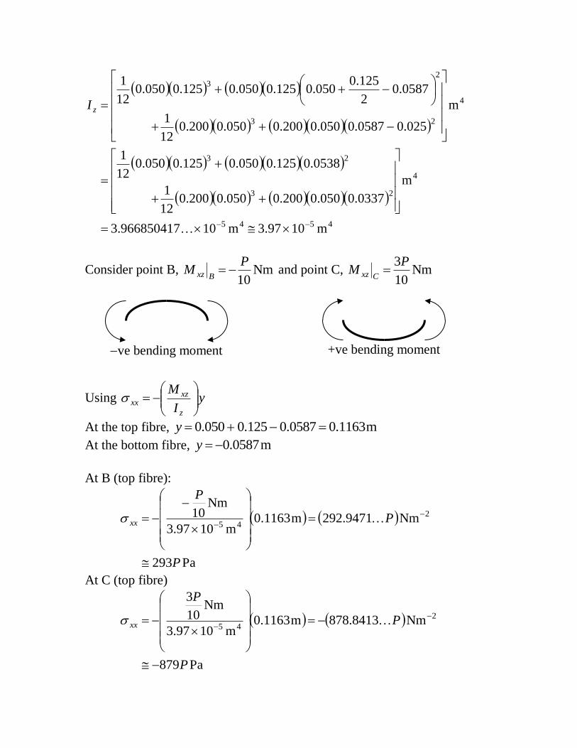
Consider point B, Nm10
PM
Bxz and point C, Nm10
3PM
Cxz
Using yI
M
z
xzxx
At the top fibre, m1163.00587.0125.0050.0 y
At the bottom fibre, m0587.0y
At B (top fibre):
Pa293
Nm9471.292m1163.0m1097.3
Nm10 2
45
P
P
P
xx
At C (top fibre)
Pa879
Nm8413.878m1163.0m1097.3
Nm10
3
2
45
P
P
P
xx
ve bending moment +ve bending moment

At B (bottom fibre)
Pa9.147
Nm8589.147m0587.0m1097.3
Nm10 2
45
P
P
P
xx
At C (bottom fibre)
Pa444
Nm5768.443m0587.0m1097.3
Nm10
3
2
45
P
P
P
xx
The largest tensile stress of Pa444P occurs at the bottom fibre at C.
The largest compressive stress of Pa879P occurs at the top fibre at C.
Since the allowable tensile stress Pa1035MPa35 6T and the
allowable compressive stress Pa10150MPa150 6C , we have
kN8.78N8288.78828
1035444 6
P
P
kN6.170N4641.170648
10150879 6
P
P
Hence, the maximum allowable value for P is kN8.78 .
The tensile stress at C is the controlling factor in determining the maximum
allowable load.

Alternatively, you may also work out the allowable loads P in each case
and take the smallest result to be the limiting load:
Point TOP FIBRE
BOTTOM FIBRE
B
Pa293Pxx Tensile
kN5.119N9249.119453
1035293 6
P
P
Pa879Pxx Compressive
kN6.170N4641.170648
10150879 6
P
P
C
Pa9.147 Pxx Compressive
kN1014N7829.1014198
101509.147 6
P
P
Pa444Pxx Tensile
kN8.78N8288.78828
1035444 6
P
P
As before, the maximum allowable value for P is kN8.78 .
To determine P based on the maximum shear stress allowable:
Shear force,
Shear stress,
We have:
Hence,
But allowable shear stress is 10 MPa. Therefore,
Hence, max. allowable value for P is still 78.8 kN.

Solutions To : Tutorial 2 Q5
From symmetry,
At section n-n,
Pa
rt ( ) ( ) ( ) ( ) ( ) ( )
11250 125 1406.25 50 28.125 21.094
11250 25 281.25 50 28.125 2.344
22500 1687.5 56.25 23.438
(a)
( )( )( )
( )( )
( )( )

(b)
( )( )( )
(( )( )
( )( ))
(c)
Largest shearing stress occurs on the section through the centroid.
( )( )( )
( )( )
( )( )

Solutions To : Tutorial 2 Q6
For rolled steel section W200x46.1, we have:
(a)
[ (
)
]
[ (
)
]
(
)
Horizontal shearing force per meter of weld is:
( )
( )
(b)
[ ( )
]
[ (
)
]
(
)

i.e.,
Alternative Solutions To : Tutorial 2 Q6
For Case (a)
Consider a unit length of the beam
Using the shear stress equation we have
yAIb
F
zzf
xy
xy (1)
A B
Fxy
z z
bf

The horizontal shearing force F induced in the beam is:
yAI
F
byAIb
F
bF
zz
xy
fzzf
xy
fxy
1
1
[ Substituting τxy from Eq. (1) ]
The shearing force is taken up by two weld lines each weld line can
withstand 500 kN.
I.e. 1000 kN for two weld lines
Hence , we have
kN
NFei
FxF
xy
xy
356
10356..
107.211
)108.594(101000
3
6
6
3
Similarly for case (b) Fxy can be calculated.