Embed Size (px)
Citation preview

T150 High Precision Temperature
Multifunction Calibrator User Manual
Wahl Instruments, Inc.
234 Old Weaverville Road
Asheville, NC 28804
Toll Free: 800-421-2853
Phone: 828-658-3131
Fax: 828-658-0728
www.palmerwahl.com
WD1056
02/04/2014 Rev B
Revised 04/22/15
T150 High Precision Temperature Calibrator
Table of Contents
A. GENERAl.................................................................................................................................................................. 1
A.1 INTRODUCTION............................................................................................................................................................1
A.1.1 About this guide.....................................................................................................................................................2
A.1.2 Unpacking.............................................................................................................................................................2
A.1.3 Returning...............................................................................................................................................................2
A.2 MATERIAL....................................................................................................................................................................3
A.2.1 General view of the unit.........................................................................................................................................3
A.2.2 Boot...................................................................................................................................................................3
A.2.3 Connection terminals............................................................................................................................................4
A.2.4 Side connectors.....................................................................................................................................................5
A.2.5 Screen....................................................................................................................................................................6
A.2.6 Keyboard...............................................................................................................................................................7
A.2.7 Batteries and charger........................................................................................................................................ 9
A.2.8 Replacing the battery pack.................................................................................................................................... 9
A.2.9 Stand…….................................................................................................................................................................9
A.2.10 Strap .................................................................................................................................................................... 9
A.3 SOFTWARE ................................................................................................................................................................. 10
A.3.1 User Interface....................................................................................................................................................... 10
A.4 SAFETY ....................................................................................................................................................................... 13
A.4.1 Compliance with safety standards......................................................................................................................... 13
A.4.2 Environmental conditions...................................................................................................................................... 13
A.4.3 Worn devices.......................................................................................................................................................... 13
A.4.4 Device destruction procedure................................................................................................................................. 13
A.4.5 Instructions ….......................................................................................................................................................... 13
A.4.6 Making measurements............................................................................................................................................. 14
A.4.7 Unusual faults and stresses.........................................................................................................................................14
A.4.8 Definitions.................................................................................................................................................................. 15
A.5 SERVICE............................................................................................................................................................................. 15
A.5.1 Software updates......................................................................................................................................................... 15
A.5.2 Recalibration................................................................................................................................................................ 16
A.5.3 Cleaning...................................................................................................................................................................... 17
A.6 POWERING ON................................................................................................................................................................... 20
A.7 MEASUREMENT ON CHANNEL V1 OR V2.............................................................................................................................21
A.7.1 Resistive temperature probes (Temperature).............................................................................................................. 22
A.7.2 Measurement by Thermocouple (Temperature)......................................................................................................... 23
A.7.3 Thermistor Measurement (Temperature)................................................................................................................... 24
A.8 SIMULATION ON CHANNEL V2......................................................................................................................................... 25
A.8.1 Generation/Simulation
Mode...........................................................................................................................................................................25
B. ADVANCED OPERATION.......................................................................................................................................28
B.1 SIMULATION MODES......................................................................................................................................................... 28
B.1.1 Manual Edit
Mode.......................................................................................................................................................................... 28
B.1.2 Incremental Edit Mode................................................................................................................................................. 29
B.1.3 Staircase mode............................................................................................................................................................ 29
B.1.4 Simple Ramp Mode...................................................................................................................................................... 31
B.1.5 Cyclic Ramp Mode....................................................................................................................................................... 32
B.1.6 Synthesizer Mode......................................................................................................................................................... 34
B.2 SCALING............................................................................................................................................................................. 37
B.3 DIFFERENTIAL MEASUREMENTS………................................................................................................................................ 38
B.4 FILTERING........................................................................................................................................................................... 39
B.5 CALIBRATED SENSORS ....................................................................................................................................................... 40
B.6 CALIBRATION PROCEDURE ................................................................................................................................................ 43
B.7 STORING THE CURRENT ACQUISITIONS……………………………………………………………….............................................................51
B.8 CONFIGURATIONS............................................................................................................................................................. 56
B.9 SETTING PARAMETERS....................................................................................................................................................... 57
B.9.1 Adjustment of contrast................................................................................................................................................ 58
B.9.2 Date and Time............................................................................................................................................................. 58
B.9.3 Preferences ............................................................................................................................................................... 59
B.10 BLUETOOTH® INTERFACE CONFIGURATION.....................................................................................................................60
C. TECHNICAL SPECIFICATIONS.....................................................................................................................................61
C.1 MEASUREMENT FUNCTION (CHANNEL 1 AND CHANNEL 2)............................................................................................ 61
C.1.1 DC voltage (Cal TC 75mV)......................................................................................................................................... 61
C.1.2 Resistance (CalPT100/PT1000)................................................................................................................................. 61
C.1.3 Temperature by thermocouples............................................................................................................................... 62
C.1.4 Temperature using resistive probes......................................................................................................................... 63
C.2 "TRANSMISSION/SIMULATION" FUNCTION.................................................................................................................... 64
C.2.1 DC Voltage (Cal TC 75mV)........................................................................................................................................ 64
C.2.2 Resistance (Cal PT100 400 Ohm ; Cal PT1000 3600 Ohm)…...................................................................................64
C.2.3 Temperature by thermocouples............................................................................................................................... 65
C.2.4 Temperature by resistive probes................................................................................................................................66
WARRANTY & CALIBRATION REGISTRATION at www.palmerwahl.com/register Registration is fast and easy. In about a minute you can have your product automatically registered for Warranty Protection and our Calibration Reminder service. Let Palmer Wahl help you protect your investment, and maintain product accuracy and compliance with ISO and other quality standards. Questions? Call Customer Service at 1-800-421-2853 or 828-658-3131 Or email: [email protected]

A. GENERAL
A.1 Introduction
The T150 is a very-high-precision portable thermometer, capable of simultaneous measurements on two separate
channels (differential measurements or comparative measurements). It is intended more particularly for calibration and
maintenance. It can measure physical and electrical quantities either on site or in the laboratory.
It can perform all the following functions:
• Measure temperatures by thermocouples, resistive probes, thermistors over 2 Insulated channels
• Recording of measurements and their display as a table or trend curve
• Simulate temperatures using thermocouples, resistive probes and thermistors on 1 isolated channel
• Calibration and generation of the calibration report
• Possibility of using calibrated sensors with memorization of the calibration factors
The T150 has many associated functions that extend its range of application:
• Relative measurement
• Results displayed based on a linear or other conversion law
• Synthesis of curves
• Compatibility with 21CFR Part 11 standard for electronic records
A number of improvements have provided it with:
• Rapid access to all its functions
• Intuitive user interface
• Bluetooth® Interface
• Advanced on-line help system
• Multi-functions keys defined step-by-step on the display
• Connections which can be made with 4 mm safety plugs
• Protection against overloads
• Powered by a rechargeable battery with rapid internal charger.
The unit is enclosed in an ABS case with rubber boot.
1
A.1.1 About this guide
This user guide consists of four parts: A, B, C and D.
Part A contains general information and a description of the hardware and software of the unit. It also contains a
paragraph on safety and user precautions.
Part B contains brief handling information and a description of the various modes of operation.
Part C contains a description of the advanced functions.
Part D contains the technical specifications of the T150.
A.1.2 Unpacking
All T150 units are mechanically and electrically checked before delivery. The necessary precautions have been taken to
ensure that they reach the user undamaged.
However, it is a good idea to make a brief check for any damage that may have occurred during transportation. If this is the
case, make an immediate claim against the carrier.
The following accessories are standard:
• This user guide
• Unit for charging the battery pack
• 4 measurement cables and 4 crocodile
• clips
• Mounting strap
A.1.3 Returning
If the unit is to be returned, it is preferable to use the original packaging and state as clearly as possible, in a note
attached to the unit, the reasons for its return.
Palmer Wahl
Instrumentation Group
234 Old Weaverville Road
Asheville, NC, 28804-1228
(800) 421-2853
(828) 658-0728
Warning
The packaging supplied with the calibrator can withstand a maximum pressure of 20 bar at 21°C (290 psi at 70°F).
2
A.2 Material
General characteristics:
• Portable unit powered by a pack of Ni-MH
• Battery life: about 6 hours, depending on the functions used
• Stand for table mounting
• Strap for carrying and on-site use
• 240 x 320 pixel liquid crystal graphical display
• Choice of language for messages and programming the functions, settings and parameters
using a keyboard with 22 keys
• Back-lit display controllable from a key on the keyboard, with automatic switch-off after a
programmable time of inactivity
• Battery charging: mains adaptor supplied with the unit or from any 10 to 14 VDC power
supply
• Adaptor characteristics: mains voltage 230 V ± 10%, 50/60 Hz.
• Charging time: 4 h max
• Case: ABS case with rubber
boot
• Dimensions: 210 mm x 110 mm
x 50 mm. Weight: 900 g with
boot and accessories
• Waterproof to IP 54 in accordance with standard EN 60529
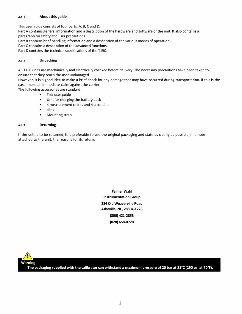
A.2.1 General view of the unit
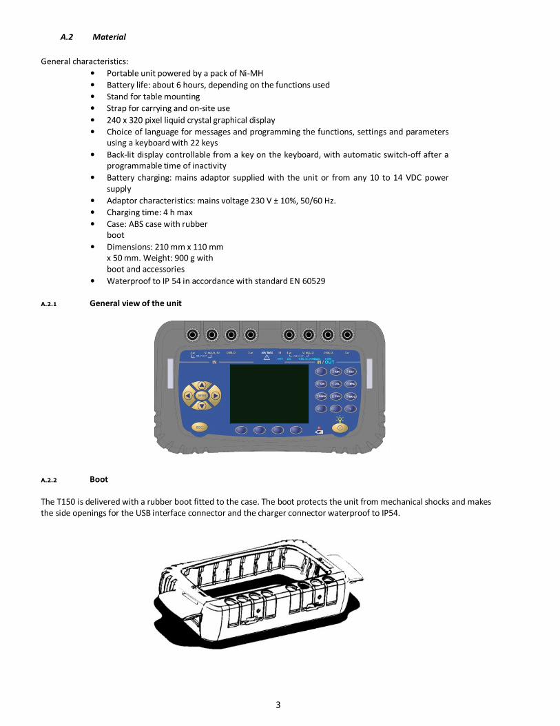
A.2.2 Boot
The T150 is delivered with a rubber boot fitted to the case. The boot protects the unit from mechanical shocks and makes
the side openings for the USB interface connector and the charger connector waterproof to IP54.
3
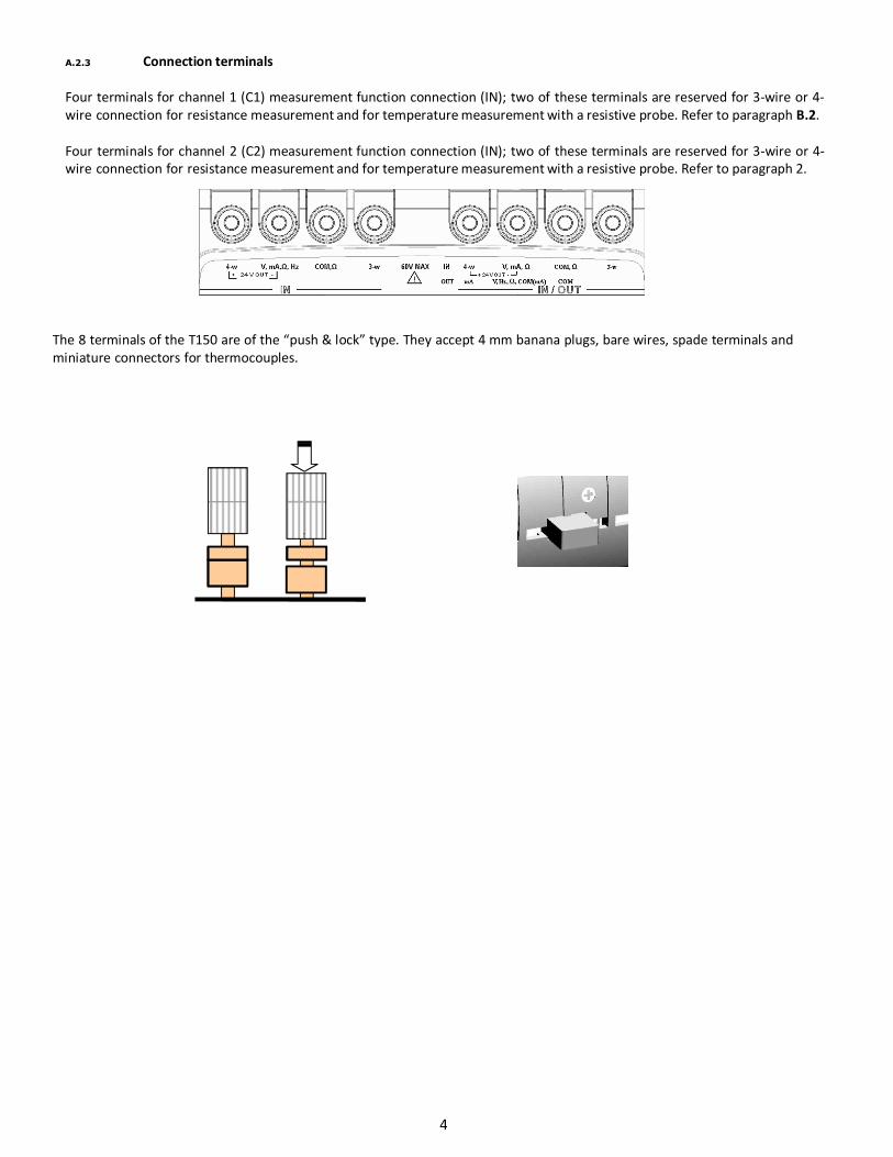
A.2.3 Connection terminals
Four terminals for channel 1 (C1) measurement function connection (IN); two of these terminals are reserved for 3-wire or 4-
wire connection for resistance measurement and for temperature measurement with a resistive probe. Refer to paragraph B.2.
Four terminals for channel 2 (C2) measurement function connection (IN); two of these terminals are reserved for 3-wire or 4-
wire connection for resistance measurement and for temperature measurement with a resistive probe. Refer to paragraph 2.
The 8 terminals of the T150 are of the “push & lock” type. They accept 4 mm banana plugs, bare wires, spade terminals and
miniature connectors for thermocouples.
4
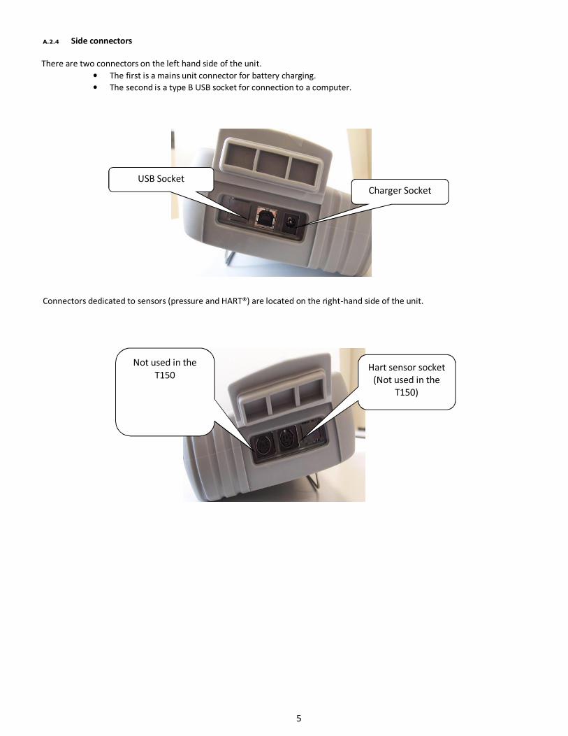
A.2.4 Side connectors
There are two connectors on the left hand side of the unit.
• The first is a mains unit connector for battery charging.
• The second is a type B USB socket for connection to a computer.
Connectors dedicated to sensors (pressure and HART®) are located on the right-hand side of the unit.
Charger Socket
USB Socket
Hart sensor socket
(Not used in the
T150)
Not used in the
T150
5
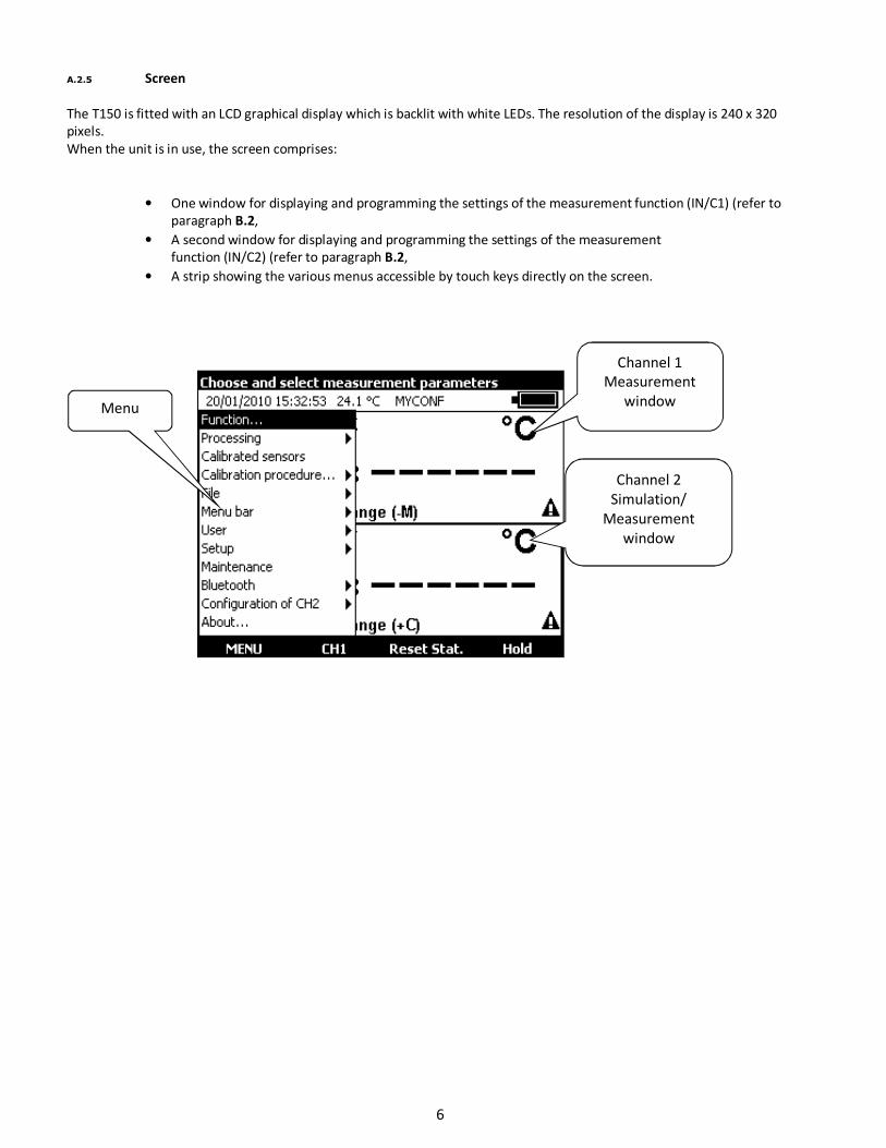
A.2.5 Screen
The T150 is fitted with an LCD graphical display which is backlit with white LEDs. The resolution of the display is 240 x 320
pixels.
When the unit is in use, the screen comprises:
• One window for displaying and programming the settings of the measurement function (IN/C1) (refer to
paragraph B.2,
• A second window for displaying and programming the settings of the measurement
function (IN/C2) (refer to paragraph B.2,
• A strip showing the various menus accessible by touch keys directly on the screen.
Channel 2
Simulation/
Measurement
window
Channel 1
Measurement
window Menu
6
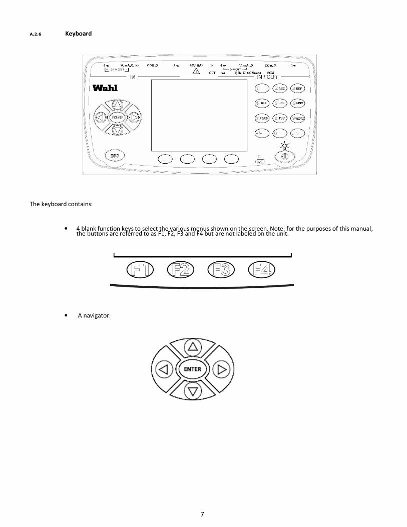
A.2.6 Keyboard
The keyboard contains:
• 4 blank function keys to select the various menus shown on the screen. Note: for the purposes of this manual,
the buttons are referred to as F1, F2, F3 and F4 but are not labeled on the unit.
• A navigator:
7

• A cancel key:
• A Start/stop key for the unit and back-lighting on/off key:
A short push switches the unit on. During operation, a short push switches the back-lighting on or off. A long push of 2
seconds switches the unit off.
• 12 alphanumeric keys for programming the parameters:
• An LED to indicate the state of charge of the battery:
8
A.2.7 Batteries and charger
Precautions to be taken if battery charge is low:
On reception of your T150 it is possible the batteries are not sufficiently charged for optimum operation or even for
starting up the device.
It is therefore required to connect the device to the mains (see paragraph A.2.4) and to wait for a few minutes before
starting it up (by pressing the On/Off button).
During normal operation:
When the symbol is flashing, the battery should be recharged as soon as possible. Connect the charger to power
system, the charge indicator (red LED) on the front panel lights up. Leave the charger switched on for about 3 hours
for a complete recharge and disconnect the charger when the charge indicator goes off on the front panel.
Precautions to be taken to improve the service life of your batteries:
The battery technology (NiMH: nickel-metal hydride) used in your T150 provides greater autonomy, however this technology requires
strict maintenance, requiring discharge cycles to avoid "memory effect". Any nickel-based battery should be fully discharged once a
month. If such maintenance is not performed, a loss of capacity can be seen that can amount to a third of the capacity. Complete
restoration then becomes more difficult if such regular maintenance is ignored.
The calibrator should be powered off for charging if not in use.
The internal charging circuit does not provide operating power for the unit. It is only for charging the battery. If the unit is left on, once the unit
becomes fully charged it will stop the charging voltage and run off the battery until the battery again requires charging. Therefore, if the unit has
been left on during the charging cycle, it is possible to have only a partial, or even a low charge, when it is disconnected for use.
The unit will still stop charging once the battery is fully charged, but if the unit is off it will not place a drain on the battery until it is turned on.
If the battery charge is too low, and the unit is being powered on, it may only flash the “Wahl” start-up screen, or even cause a system lock up. In
either case plug the charger into the unit and allow a couple of minutes for normal operation to restore. If the unit is still locked up try depressing
the “ESC” button and the Power button at the same time for about 15-20 seconds. This should cause a system reset and return to normal
operation.
If the above symptoms continue after the battery has had a proper full charge cycle (minimum 3-4 hours while powered off) it may indicate a
depleted battery pack requiring replacement.
Warning
ONLY USE THE ADAPTOR SUPPLIED WITH THE CALIBRATOR.
A.2.8 Replacing the battery pack
The battery pack should be changed once a year for optimal autonomy of instrument. To replace the battery pack,
contact your dealer.
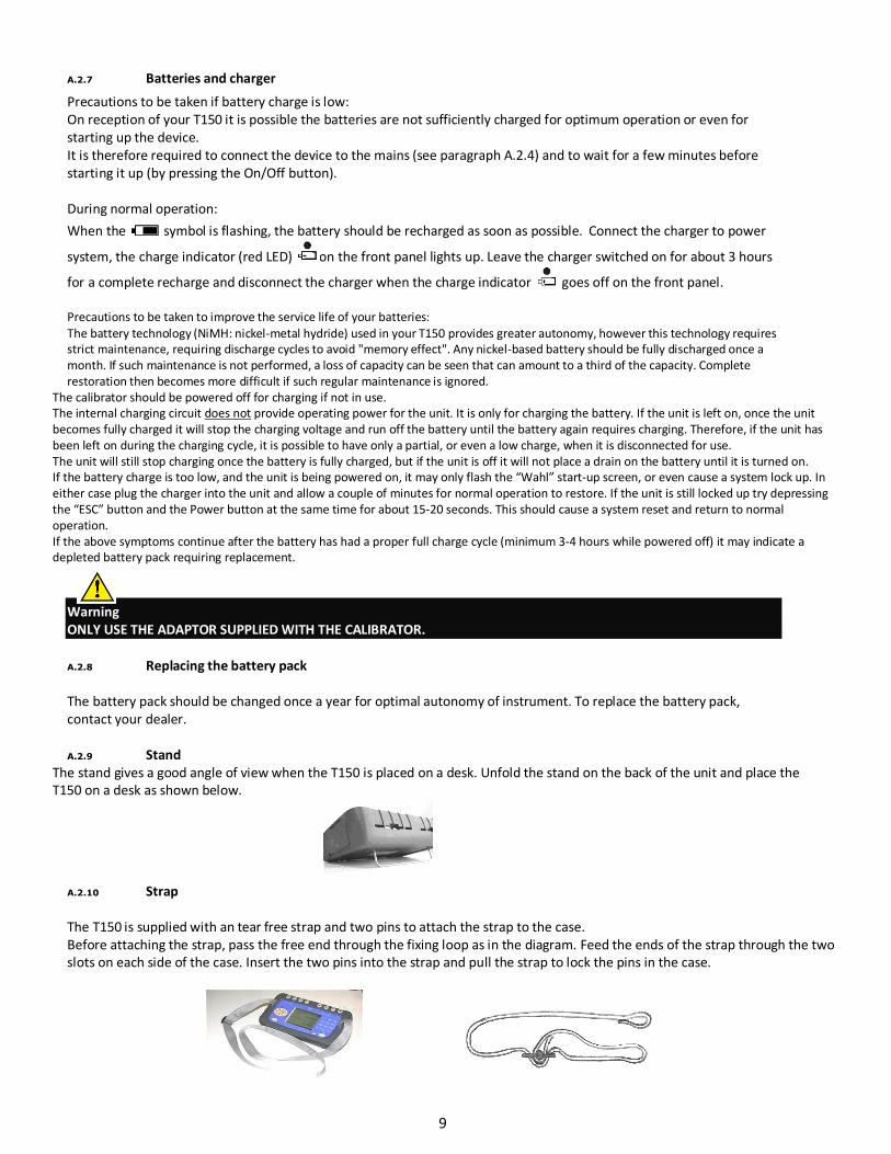
A.2.9 Stand
The stand gives a good angle of view when the T150 is placed on a desk. Unfold the stand on the back of the unit and place the
T150 on a desk as shown below.
A.2.10 Strap
The T150 is supplied with an tear free strap and two pins to attach the strap to the case.
Before attaching the strap, pass the free end through the fixing loop as in the diagram. Feed the ends of the strap through the two
slots on each side of the case. Insert the two pins into the strap and pull the strap to lock the pins in the case.
9
A.3 Software
The firmware of the T150 is stored in flash memory. It is therefore relatively easy to update the firmware when a new version
is available. Refer to paragraph A.5.1 for detailed information on updating the firmware.
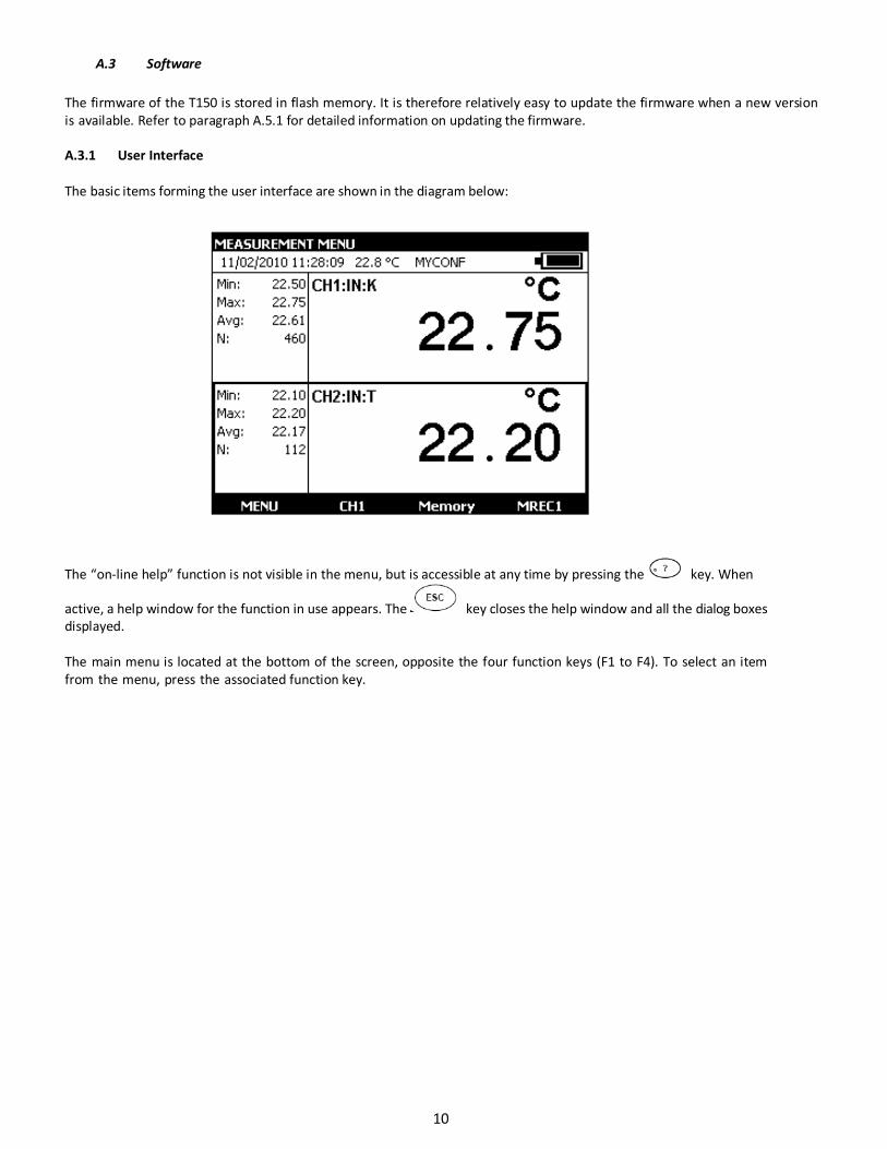
A.3.1 User Interface
The basic items forming the user interface are shown in the diagram below:
The “on-line help” function is not visible in the menu, but is accessible at any time by pressing the key. When
active, a help window for the function in use appears. The key closes the help window and all the dialog boxes
displayed.
The main menu is located at the bottom of the screen, opposite the four function keys (F1 to F4). To select an item
from the menu, press the associated function key.
10
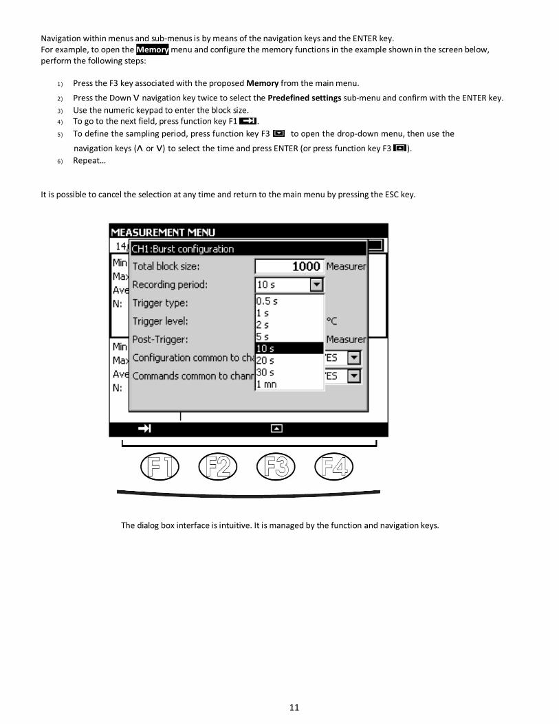
Navigation within menus and sub-menus is by means of the navigation keys and the ENTER key.
For example, to open the Memory menu and configure the memory functions in the example shown in the screen below,
perform the following steps:
1) Press the F3 key associated with the proposed Memory from the main menu.
2) Press the Down ᴠ navigation key twice to select the Predefined settings sub-menu and confirm with the ENTER key.
3) Use the numeric keypad to enter the block size.
4) To go to the next field, press function key F1 .
5) To define the sampling period, press function key F3 to open the drop-down menu, then use the
navigation keys (ᴧ or ᴠ) to select the time and press ENTER (or press function key F3 ).
6) Repeat…
It is possible to cancel the selection at any time and return to the main menu by pressing the ESC key.
The dialog box interface is intuitive. It is managed by the function and navigation keys.
11
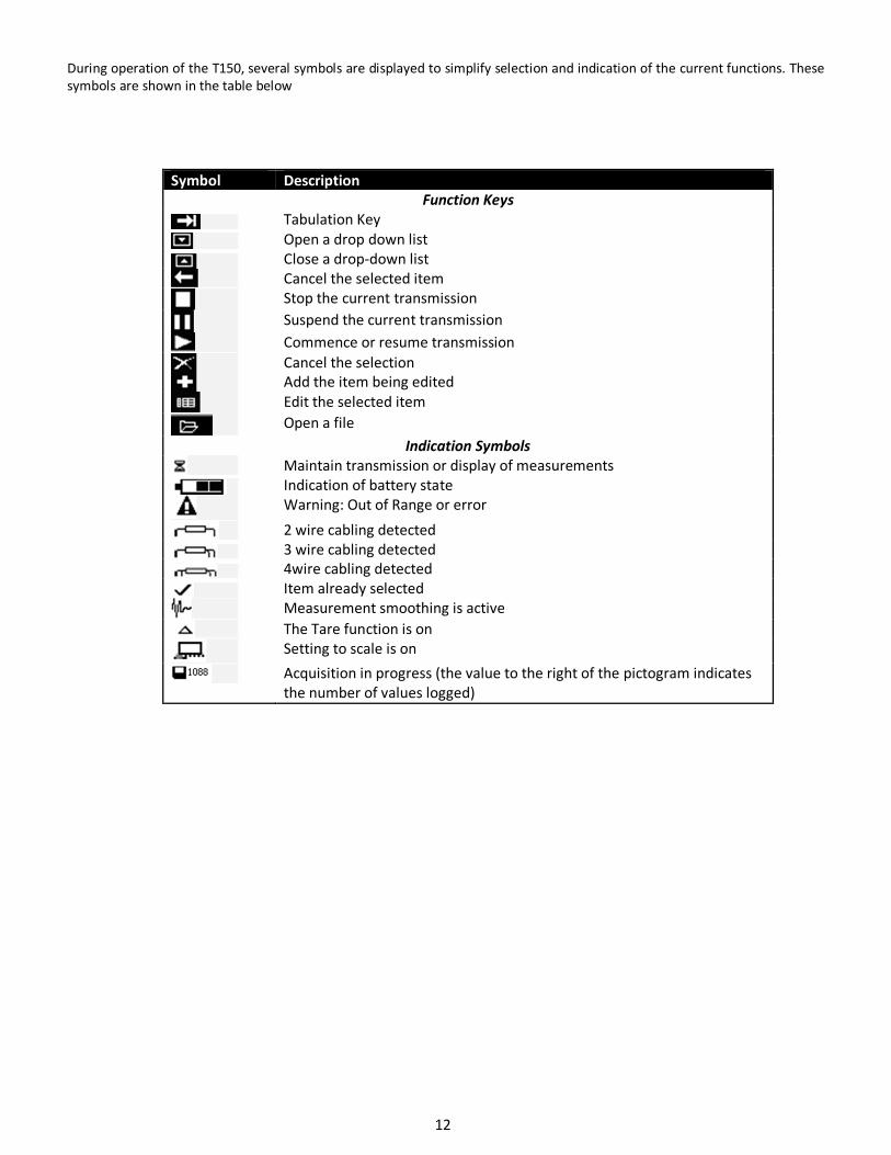
During operation of the T150, several symbols are displayed to simplify selection and indication of the current functions. These
symbols are shown in the table below
Symbol Description
Function Keys
Tabulation Key
Open a drop down list
Close a drop-down list
Cancel the selected item
Stop the current transmission
Suspend the current transmission
Commence or resume transmission
Cancel the selection
Add the item being edited
Edit the selected item
Open a file
Indication Symbols
Maintain transmission or display of measurements
Indication of battery state
Warning: Out of Range or error
2 wire cabling detected
3 wire cabling detected
4wire cabling detected
Item already selected
Measurement smoothing is active
The Tare function is on
Setting to scale is on
Acquisition in progress (the value to the right of the pictogram indicates
the number of values logged)
12
A.4 Safety
A.4.1 Compliance with safety standards
The unit complies with applicable standards:
- Safety directive 2006/95/CE with standard EN611010-1
- Directive CEM 2004/108/CE with standard EN61326
- Radio directive 1999/5/CE with standards EN300-328 and EN301-489
These instructions for use contain information and warnings which must be observed by the user to protect the latter
against the dangers of electricity, to ensure the safe operation of the device and to protect it against any mishandling which
could damage or compromise the safety of use of the device.
A.4.2 Environmental conditions
As per publication EN 60359
Range of application of standards from 0 to 2,000 m.
Reference temperature range: 23°C ± 5°C, relative humidity: 45 % to 75 %.
Nominal operating range: -10°C to +50°C, relative humidity: 20 % to 80 % non-condensing.
Operating range limit: -15°C to +55°C, relative humidity: 10 % to 80 % (70 % at 55°C).
Storage and transport temperature range limit: - 30°C to + 60°C (without the batteries).
A.4.3 Disposal of device
Worn electrical devices can pollute the environment. We recommend you refrain from disposing of this device in an ordinary
waste bin, but rather that you use the recycling centers available locally. If not, you can return the device to us, and we will take
care of its disposal free of charge.
A.4.3.1 Waste generated by the device
A.4.4 Device destruction procedure
Open unit: unscrew screws from lower casing (after removing boot).
Separate both shells and disconnect battery pack
A.4.5 Instructions
The unit is designed to be used in complete safety if the instructions given in the accompanying documents are followed. Any
use apart from those defined, may affect the safety of the operator and is therefore dangerous and not recommended.
13
A.4.6 Making measurements
Measuring wires and leads must be in good condition and must be replaced if their insulation appears defective
(insulation cut, burned, etc.).
When the unit is connected to the measurement circuit, the terminals may be dangerous. Also, never place your hands near a
terminal, whether in use or not. This advice also applies to the battery charger sockets and the USB link connected directly or
indirectly to the terminals of the unit. Any work on these circuits must be carried out with the unit disconnected from any other
external circuit.
Never exceed the limiting values of protection indicated in the specifications.
When the order of magnitude of the value to be measured is unknown, make sure that the starting measurement range is the
highest possible, or choose the automatic range selection mode.
Before changing the function, disconnect the wires for measuring the external circuit. When measuring current and/or voltage,
even if low, remember that the circuits may be live with respect to earth, at a voltage that is dangerous for the operator.
Never carry out resistance measurements on a live
circuit.
A.4.7 Unusual faults and stresses
Whenever it is believed that the protection has been damaged, switch off the unit and ensure that it is not used prematurely.
The protection may have been damaged if, for example:
There is obvious damage to the unit.
The unit is no longer able to make accurate measurements.
The unit has been stored under unfavorable conditions.
The unit has been subjected to severe stress during transportation.
14
A.4.8 Definitions
A.4.8.1 Definition of the installation category
This is also known as the overvoltage category.
It is the classification of the installation according to standard limits for transient overvoltage’s (standard CEI 664).
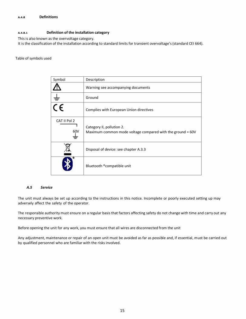
Table of symbols used
A.5 Service
The unit must always be set up according to the instructions in this notice. Incomplete or poorly executed setting up may
adversely affect the safety of the operator.
The responsible authority must ensure on a regular basis that factors affecting safety do not change with time and carry out any
necessary preventive work.
Before opening the unit for any work, you must ensure that all wires are disconnected from the unit
Any adjustment, maintenance or repair of an open unit must be avoided as far as possible and, if essential, must be carried out
by qualified personnel who are familiar with the risks involved.
Symbol Description
Warning see accompanying documents
Ground
Complies with European Union directives
CAT II Pol 2
60V Category II, pollution 2.
Maximum common mode voltage compared with the ground = 60V
Disposal of device: see chapter A.3.3
Bluetooth ®compatible unit
15
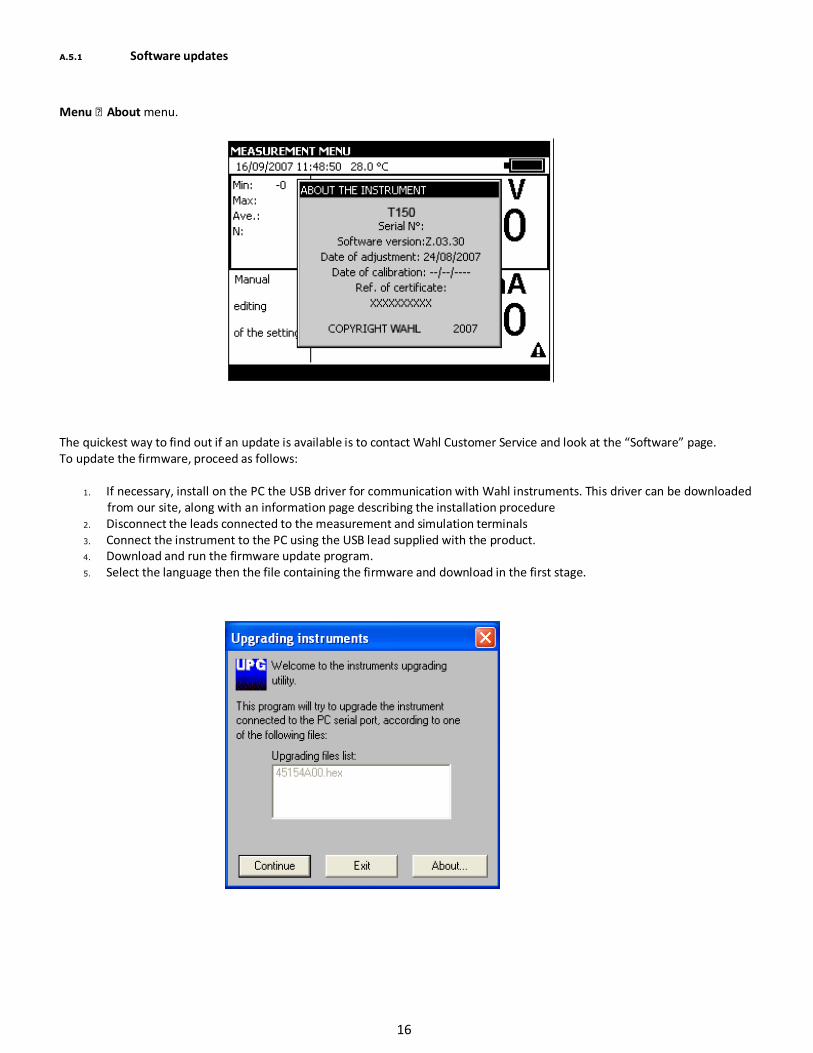
A.5.1 Software updates
Menu About menu.
The quickest way to find out if an update is available is to contact Wahl Customer Service and look at the “Software” page.
To update the firmware, proceed as follows:
1. If necessary, install on the PC the USB driver for communication with Wahl instruments. This driver can be downloaded
from our site, along with an information page describing the installation procedure
2. Disconnect the leads connected to the measurement and simulation terminals
3. Connect the instrument to the PC using the USB lead supplied with the product.
4. Download and run the firmware update program.
5. Select the language then the file containing the firmware and download in the first stage.
16
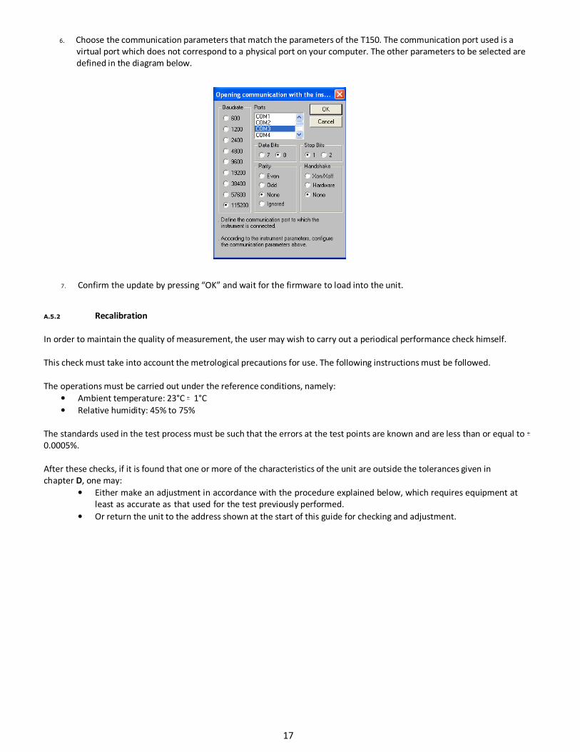
6. Choose the communication parameters that match the parameters of the T150. The communication port used is a
virtual port which does not correspond to a physical port on your computer. The other parameters to be selected are
defined in the diagram below.
7. Confirm the update by pressing “OK” and wait for the firmware to load into the unit.
A.5.2 Recalibration
In order to maintain the quality of measurement, the user may wish to carry out a periodical performance check himself.
This check must take into account the metrological precautions for use. The following instructions must be followed.
The operations must be carried out under the reference conditions, namely:
• Ambient temperature: 23°C 1°C
• Relative humidity: 45% to 75%
The standards used in the test process must be such that the errors at the test points are known and are less than or equal to
0.0005%.
After these checks, if it is found that one or more of the characteristics of the unit are outside the tolerances given in
chapter D, one may:
• Either make an adjustment in accordance with the procedure explained below, which requires equipment at
least as accurate as that used for the test previously performed.
• Or return the unit to the address shown at the start of this guide for checking and adjustment.
17
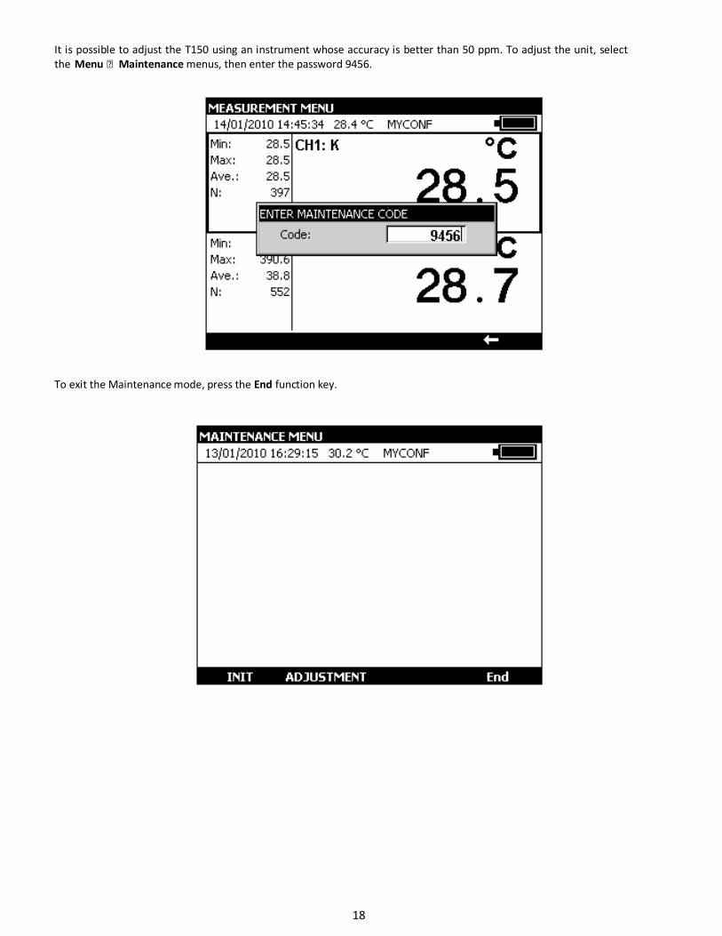
It is possible to adjust the T150 using an instrument whose accuracy is better than 50 ppm. To adjust the unit, select
the Menu Maintenance menus, then enter the password 9456.
To exit the Maintenance mode, press the End function key.
18
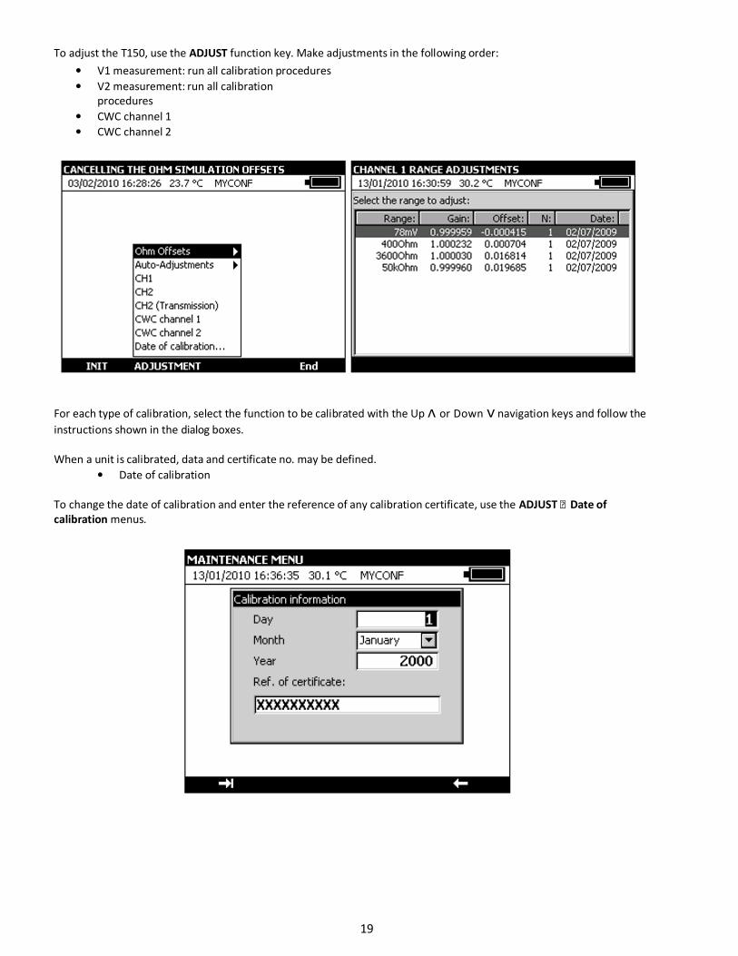
To adjust the T150, use the ADJUST function key. Make adjustments in the following order:
• V1 measurement: run all calibration procedures
• V2 measurement: run all calibration
procedures
• CWC channel 1
• CWC channel 2
For each type of calibration, select the function to be calibrated with the Up ᴧ or Down ᴠ navigation keys and follow the
instructions shown in the dialog boxes.
When a unit is calibrated, data and certificate no. may be defined.
• Date of calibration
To change the date of calibration and enter the reference of any calibration certificate, use the ADJUST Date of
calibration menus.
19
A.5.3 Cleaning
In order to use the unit in complete safety, users must carefully read paragraph A.4 which, among other things, deals
with safety before handling. It is advisable also to read the following paragraphs:
A.1.2 Unpacking
A.2.7 Batteries and charger
A.5.3 Cleaning A.6 Powering on
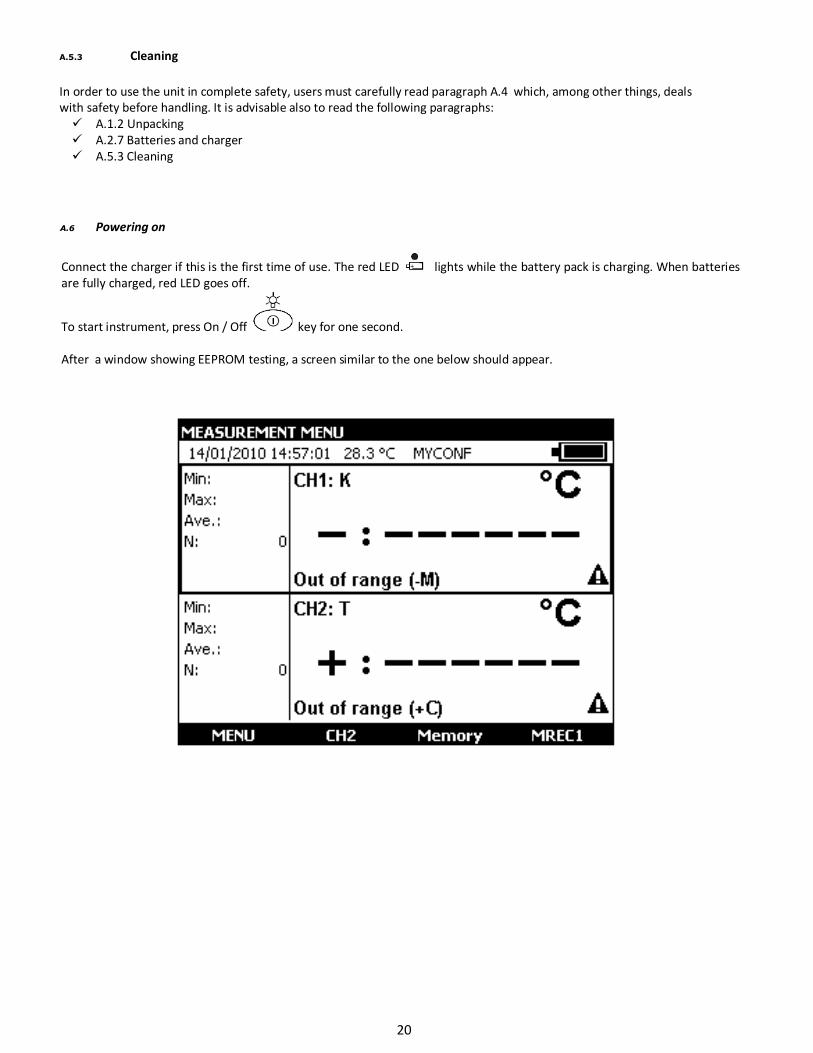
Connect the charger if this is the first time of use. The red LED lights while the battery pack is charging. When batteries
are fully charged, red LED goes off.
To start instrument, press On / Off key for one second.
After a window showing EEPROM testing, a screen similar to the one below should appear.
20

A.7 Measurement on channel V1 or V2
To change the Measurement functions from channel V1, a rectangle should surround the top window on the screen. If it is
not the case, select channel by activating the measurement window with function key F2 (V1).
In order to be able to change the channel C2 measurement functions, there must be a rectangle around the lower window on
the screen. If this is not the case, select the channel by pressing function key F2 (C2) to activate the measurement window.
To choose a measurement function, press key F1 (Menu).
Select the Function … menu with the navigation keys and confirm with the ENTER key.
The MEASUREMENT MENU dialog box is displayed.
21
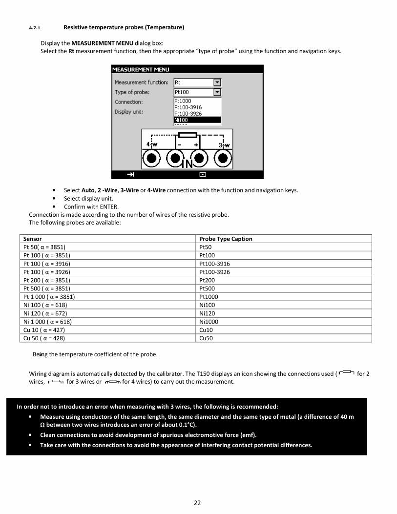
A.7.1 Resistive temperature probes (Temperature)
Display the MEASUREMENT MENU dialog box:
Select the Rt measurement function, then the appropriate “type of probe” using the function and navigation keys.
• Select Auto, 2 -Wire, 3-Wire or 4-Wire connection with the function and navigation keys.
• Select display unit.
• Confirm with ENTER.
Connection is made according to the number of wires of the resistive probe.
The following probes are available:
Sensor Probe Type Caption
Pt 50( α = 3851) Pt50
Pt 100 ( α = 3851) Pt100
Pt 100 ( α = 3916) Pt100-3916
Pt 100 ( α = 3926) Pt100-3926
Pt 200 ( α = 3851) Pt200
Pt 500 ( α = 3851) Pt500
Pt 1 000 ( α = 3851) Pt1000
Ni 100 ( α = 618) Ni100
Ni 120 ( α = 672) Ni120
Ni 1 000 ( α = 618) Ni1000
Cu 10 ( α = 427) Cu10
Cu 50 ( α = 428) Cu50
Being the temperature coefficient of the probe.
Wiring diagram is automatically detected by the calibrator. The T150 displays an icon showing the connections used ( for 2
wires, for 3 wires or for 4 wires) to carry out the measurement.
In order not to introduce an error when measuring with 3 wires, the following is recommended:
• Measure using conductors of the same length, the same diameter and the same type of metal (a difference of 40 m
Ω between two wires introduces an error of about 0.1°C).
• Clean connections to avoid development of spurious electromotive force (emf).
• Take care with the connections to avoid the appearance of interfering contact potential differences.
22
Note:
By changing the display unit, the ohmic value of the connected probe can be measured: The following ranges are available:
Range 400 ohms
(probe type: PT100)
3600 ohms
(probe type: PT1000)
Resolution 1 m ohm 10 m ohm
Automatic wire detection 2, 3 and 4 wires 2, 3 and 4 wires
Measuring current 0.2 to 0.45 mA 0.2 to 0.45 mA
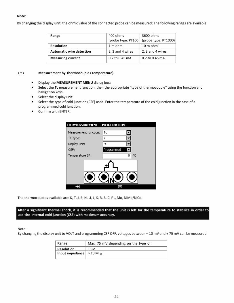
A.7.2 Measurement by Thermocouple (Temperature)
• Display the MEASUREMENT MENU dialog box:
• Select the Tc measurement function, then the appropriate “type of thermocouple” using the function and
navigation keys.
• Select the display unit
• Select the type of cold junction (CSF) used. Enter the temperature of the cold junction in the case of a
programmed cold junction.
• Confirm with ENTER.
The thermocouples available are: K, T, J, E, N, U, L, S, R, B, C, PL, Mo, NiMo/NiCo.
After a significant thermal shock, it is recommended that the unit is left for the temperature to stabilize in order to
use the internal cold junction (CSF) with maximum accuracy.
Note:
By changing the display unit to VOLT and programming CSF OFF, voltages between – 10 mV and + 75 mV can be measured.
Range Max. 75 mV depending on the type of
thermocouple used (TC measurement function) Resolution 1 uV Input impedance > 10 M
23
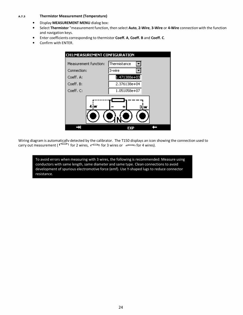
A.7.3 Thermistor Measurement (Temperature)
• Display MEASUREMENT MENU dialog box:
• Select Thermistor "measurement function, then select Auto, 2-Wire, 3-Wire or 4-Wire connection with the function
and navigation keys.
• Enter coefficients corresponding to thermistor Coeff. A, Coeff. B and Coeff. C.
• Confirm with ENTER.
Wiring diagram is automatically detected by the calibrator. The T150 displays an icon showing the connection used to
carry out measurement ( for 2 wires, for 3 wires or for 4 wires).
To avoid errors when measuring with 3 wires, the following is recommended: Measure using
conductors with same length, same diameter and same type. Clean connections to avoid
development of spurious electromotive force (emf). Use Y-shaped lugs to reduce connector
resistance.
24
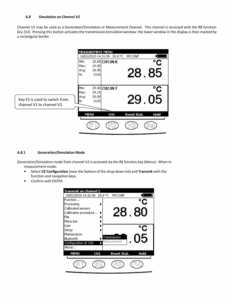
A.8 Simulation on Channel V2
Channel V2 may be used as a Generation/Simulation or Measurement Channel. This channel is accessed with the F2 function
key (V2). Pressing this button activates the transmission/simulation window: the lower window in the display is then marked by
a rectangular border.
A.8.1 Generation/Simulation Mode
Generation/Simulation mode from channel V2 is accessed via the F1 function key (Menu). When in
measurement mode:
• Select V2 Configuration (near the bottom of the drop-down list) and Transmit with the
function and navigation keys.
• Confirm with ENTER.
Key F2 is used to switch from
channel V1 to channel V2.
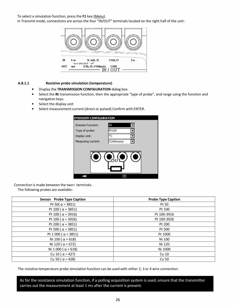
To select a simulation function, press the F1 key (Menu).
In Transmit mode, connections are across the four "IN/OUT" terminals located on the right half of the unit:
A.8.1.1 Resistive probe simulation (temperature)
• Display the TRANSMISSION CONFIGURATION dialog box:
• Select the Rt transmission function, then the appropriate “type of probe”, and range using the function and
navigation keys.
• Select the display unit
• Select measurement current (direct or pulsed) Confirm with ENTER.
Connection is made between the two terminals.
The following probes are available:
The resistive temperature probe simulation function can be used with either 2, 3 or 4 wire connection.
Sensor Probe Type Caption Probe Type Caption
Pt 50( α = 3851) Pt 50
Pt 100 ( α = 3851) Pt 100
Pt 100 ( α = 3916) Pt 100-3916
Pt 100 ( α = 3926) Pt 100-3926
Pt 200 ( α = 3851) Pt 200
Pt 500 ( α = 3851) Pt 500
Pt 1 000 ( α = 3851) Pt 1000
Ni 100 ( α = 618) Ni 100
Ni 120 ( α = 672) Ni 120
Ni 1 000 ( α = 618) Ni 1000
Cu 10 ( α = 427) Cu 10
Cu 50 ( α = 428) Cu 50
As for the resistance simulation function, if a polling acquisition system is used, ensure that the transmitter
carries out the measurement at least 1 ms after the current is present.
26
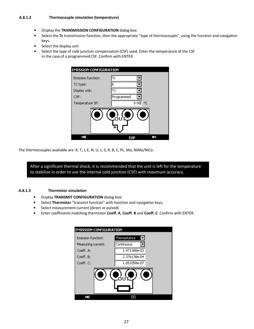
A.8.1.2 Thermocouple simulation (temperature)
• Display the TRANSMISSION CONFIGURATION dialog box:
• Select the Tc transmission function, then the appropriate “type of thermocouple”, using the function and navigation
keys.
• Select the display unit
• Select the type of cold junction compensation (CSF) used. Enter the temperature of the CSF
in the case of a programmed CSF. Confirm with ENTER
The thermocouples available are: K, T, J, E, N, U, L, S, R, B, C, PL, Mo, NiMo/NiCo.
A.8.1.3 Thermistor simulation
• Display TRANSMIT CONFIGURATION dialog box:
• Select Thermistor "transmit function" with function and navigation keys.
• Select measurement current (direct or pulsed)
• Enter coefficients matching thermistor Coeff. A, Coeff. B and Coeff. C. Confirm with ENTER.
After a significant thermal shock, it is recommended that the unit is left for the temperature
to stabilize in order to use the internal cold junction (CSF) with maximum accuracy.
27

B. ADVANCED OPERATION
B.1 Simulation Modes
Several transmission modes are available in the T150 to facilitate rapid checking and calibration of instruments and transmitters.
To change the transmission mode, open the transmission window using the OUT function key (F2).
When the transmission window is open, the T150 is set by default to the Manual edit mode.
To access the other modes, select the Mode menu using function key F4. Select a transmission mode using the Up/Down keys
of the navigator and confirm with ENTER.
To exit a transmission mode and return to the default mode, press the ESC key.
B.1.1 Manual Edit Mode
In this mode, the value to be transmitted may be entered directly using the alphanumeric keys.
The value entered appears at the bottom of the transmission window during entry.
To cancel the entry, press the ESC key. To transmit the value entered, confirm with the ENTER key.
Setting entered
manually
28
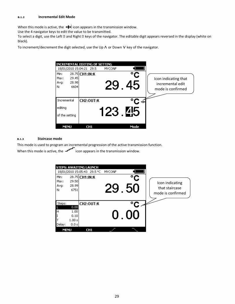
B.1.2 Incremental Edit Mode
When this mode is active, the icon appears in the transmission window.
Use the 4 navigator keys to edit the value to be transmitted.
To select a digit, use the Left and Right keys of the navigator. The editable digit appears reversed in the display (white on
black).
To increment/decrement the digit selected, use the Up ᴧ or Down ᴠ key of the navigator.
B.1.3 Staircase mode
This mode is used to program an incremental progression of the active transmission function.
When this mode is active, the icon appears in the transmission window.
Icon indicating that
incremental edit
mode is confirmed
Icon indicating
that staircase
mode is confirmed
29
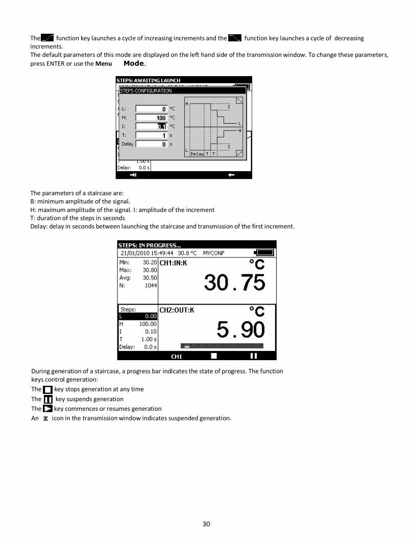
The function key launches a cycle of increasing increments and the function key launches a cycle of decreasing
increments.
The default parameters of this mode are displayed on the left hand side of the transmission window. To change these parameters,
press ENTER or use the Menu Mode.
The parameters of a staircase are:
B: minimum amplitude of the signal.
H: maximum amplitude of the signal. I: amplitude of the increment
T: duration of the steps in seconds
Delay: delay in seconds between launching the staircase and transmission of the first increment.
During generation of a staircase, a progress bar indicates the state of progress. The function
keys control generation:
The key stops generation at any time
The key suspends generation
The key commences or resumes generation
An icon in the transmission window indicates suspended generation.
30
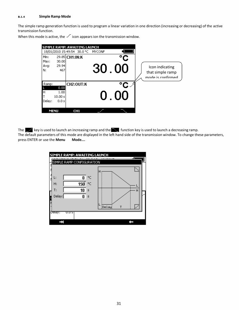
B.1.4 Simple Ramp Mode
The simple ramp generation function is used to program a linear variation in one direction (increasing or decreasing) of the active
transmission function.
When this mode is active, the icon appears ion the transmission window.
The key is used to launch an increasing ramp and the function key is used to launch a decreasing ramp.
The default parameters of this mode are displayed in the left hand side of the transmission window. To change these parameters,
press ENTER or use the Menu Mode….
Icon indicating
that simple ramp
mode is confirmed
31
The parameters of a simple ramp are:
B: minimum amplitude of the signal.
H: maximum amplitude of the signal.
T: duration of the ramp in seconds.
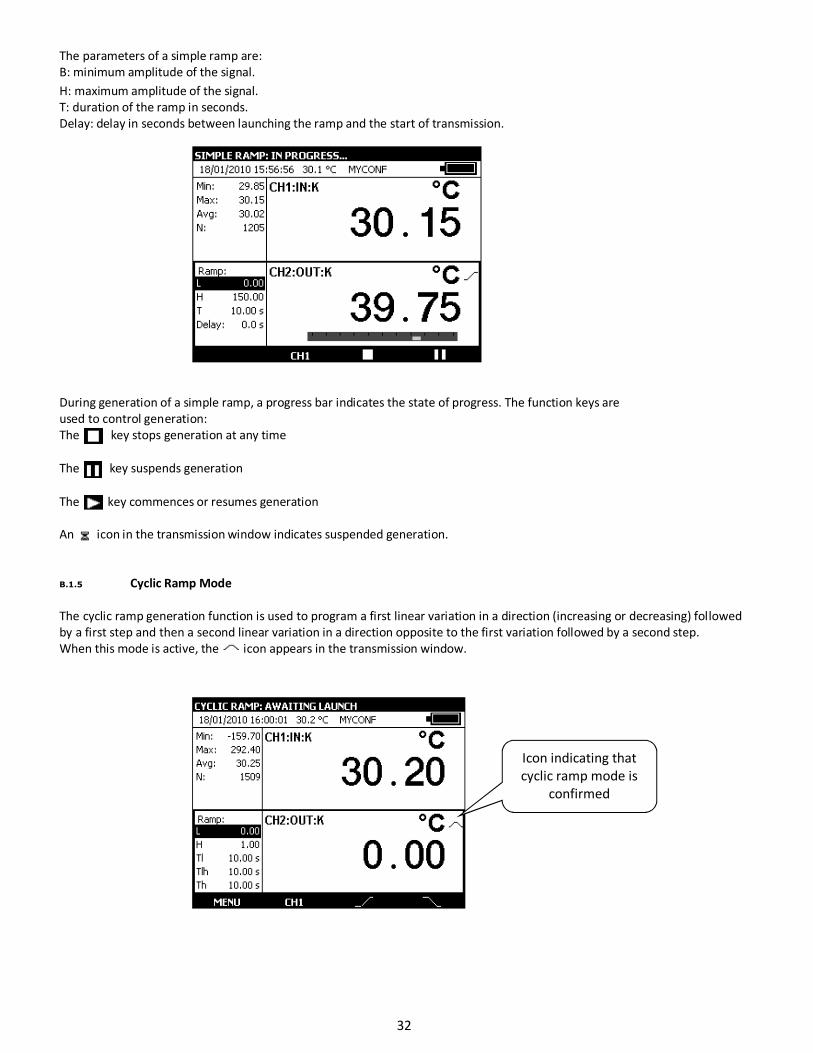
Delay: delay in seconds between launching the ramp and the start of transmission.
During generation of a simple ramp, a progress bar indicates the state of progress. The function keys are
used to control generation:
The key stops generation at any time
The key suspends generation
The key commences or resumes generation
An icon in the transmission window indicates suspended generation.
B.1.5 Cyclic Ramp Mode
The cyclic ramp generation function is used to program a first linear variation in a direction (increasing or decreasing) followed
by a first step and then a second linear variation in a direction opposite to the first variation followed by a second step.
When this mode is active, the icon appears in the transmission window.
Icon indicating that
cyclic ramp mode is
confirmed
32
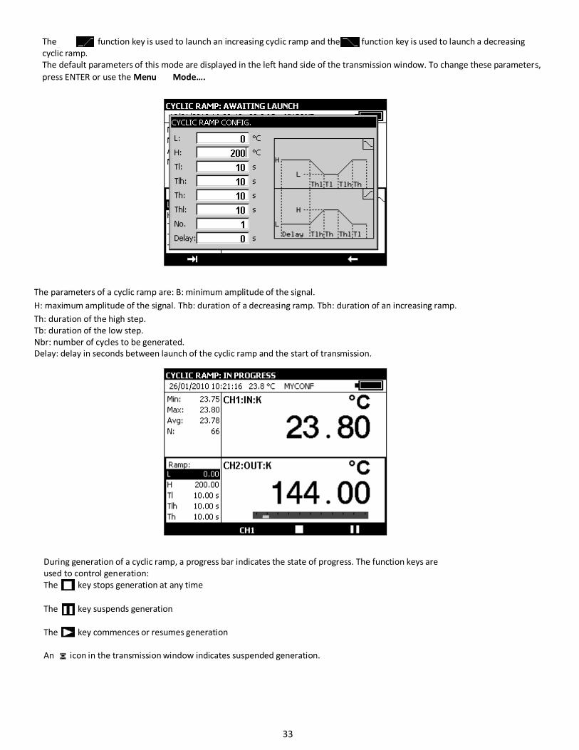
The function key is used to launch an increasing cyclic ramp and the function key is used to launch a decreasing
cyclic ramp.
The default parameters of this mode are displayed in the left hand side of the transmission window. To change these parameters,
press ENTER or use the Menu Mode….
The parameters of a cyclic ramp are: B: minimum amplitude of the signal.
H: maximum amplitude of the signal. Thb: duration of a decreasing ramp. Tbh: duration of an increasing ramp.
Th: duration of the high step.
Tb: duration of the low step.
Nbr: number of cycles to be generated.
Delay: delay in seconds between launch of the cyclic ramp and the start of transmission.
During generation of a cyclic ramp, a progress bar indicates the state of progress. The function keys are
used to control generation:
The key stops generation at any time
The key suspends generation
The key commences or resumes generation
An icon in the transmission window indicates suspended generation.
33

B.1.6 Synthesizer Mode
The synthesizer function is used:
• To store up to 100 transmission values in permanent memory,
• To recall and transmit the contents of these memories manually or automatically.
When this mode is active the icon appears in the transmission window.
The key is used to launch generation of values in increasing order and the function key is used to launch generation of
values in decreasing order.
The default parameters of this mode are displayed in the left hand side of the transmission window.
The parameters of the synthesizer mode are:
First point no.: number of the first point in a cycle
Last point no.: number of the last point in a cycle
T: the duration for which a point is transmitted.
Nbr: the number of polling cycles
Delay: delay between launch and transmission of the first point.
To change these parameters, use the Menu Synthesizer… Parameters…
Icon indicating that
synthesizer mode is
confirmed
34
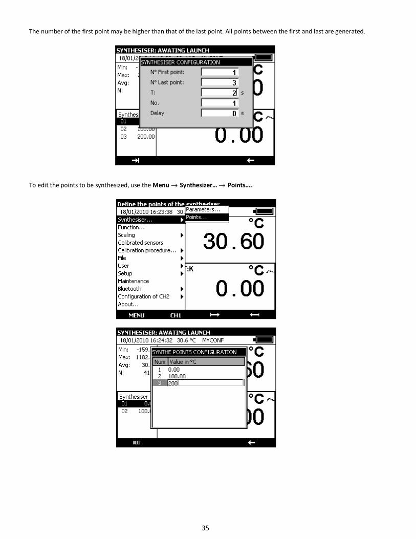
The number of the first point may be higher than that of the last point. All points between the first and last are generated.
To edit the points to be synthesized, use the Menu → Synthesizer… → Points….
35
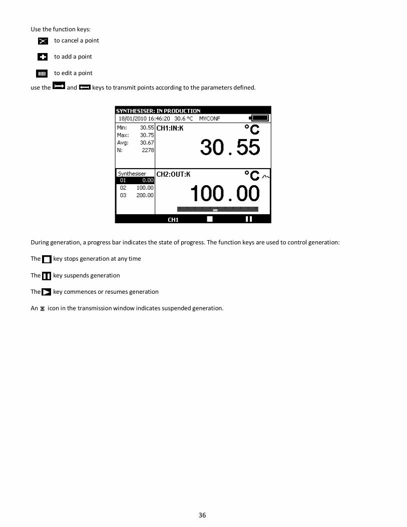
Use the function keys:
to cancel a point
to add a point
to edit a point
use the and keys to transmit points according to the parameters defined.
During generation, a progress bar indicates the state of progress. The function keys are used to control generation:
The key stops generation at any time
The key suspends generation
The key commences or resumes generation
An icon in the transmission window indicates suspended generation.
36
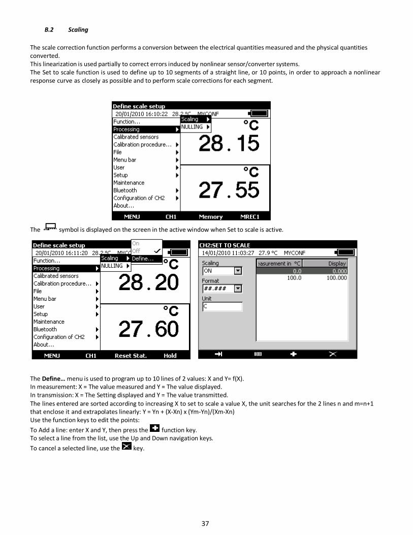
B.2 Scaling
The scale correction function performs a conversion between the electrical quantities measured and the physical quantities
converted.
This linearization is used partially to correct errors induced by nonlinear sensor/converter systems.
The Set to scale function is used to define up to 10 segments of a straight line, or 10 points, in order to approach a nonlinear
response curve as closely as possible and to perform scale corrections for each segment.
The symbol is displayed on the screen in the active window when Set to scale is active.
The Define… menu is used to program up to 10 lines of 2 values: X and Y= f(X).
In measurement: X = The value measured and Y = The value displayed.
In transmission: X = The Setting displayed and Y = The value transmitted.
The lines entered are sorted according to increasing X to set to scale a value X, the unit searches for the 2 lines n and m=n+1
that enclose it and extrapolates linearly: Y = Yn + (X-Xn) x (Ym-Yn)/(Xm-Xn)
Use the function keys to edit the points:
To Add a line: enter X and Y, then press the function key.
To select a line from the list, use the Up and Down navigation keys.
To cancel a selected line, use the key.
37
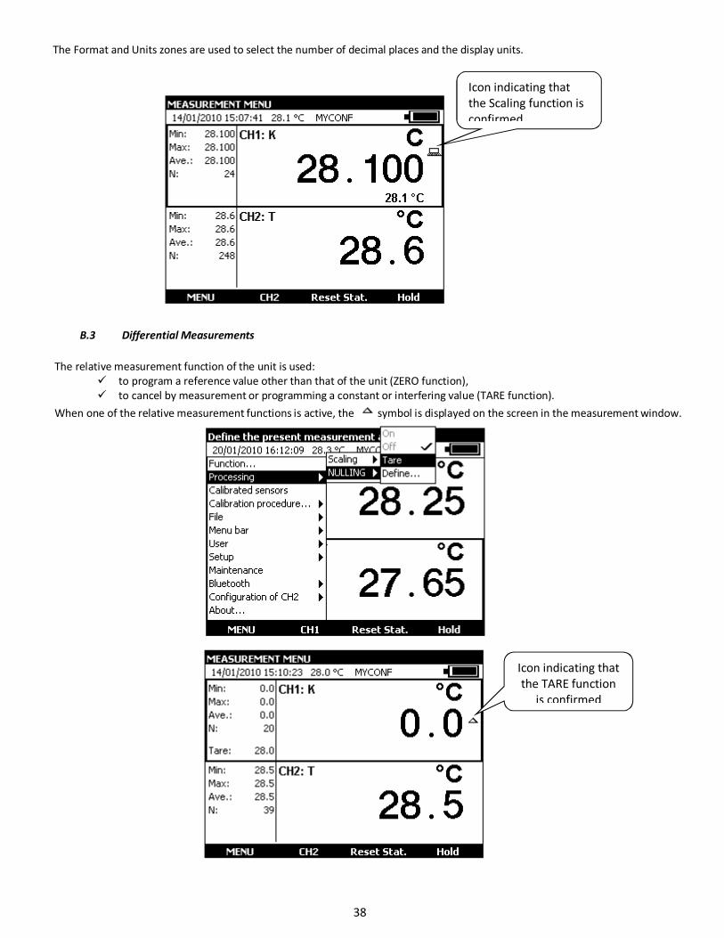
The Format and Units zones are used to select the number of decimal places and the display units.
B.3 Differential Measurements
The relative measurement function of the unit is used:
to program a reference value other than that of the unit (ZERO function),
to cancel by measurement or programming a constant or interfering value (TARE function).
When one of the relative measurement functions is active, the symbol is displayed on the screen in the measurement window.
Icon indicating that
the Scaling function is
confirmed
Icon indicating that
the TARE function
is confirmed
38
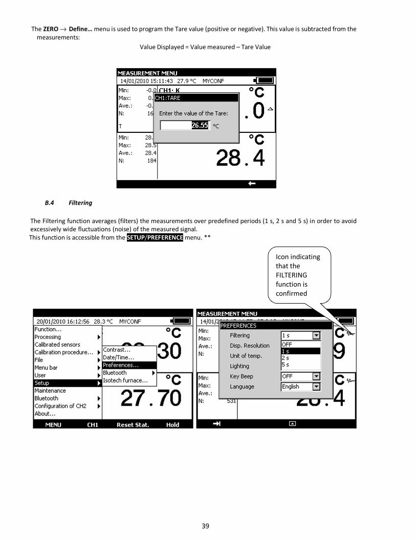
The ZERO → Define… menu is used to program the Tare value (positive or negative). This value is subtracted from the
measurements:
Value Displayed = Value measured – Tare Value
B.4 Filtering
The Filtering function averages (filters) the measurements over predefined periods (1 s, 2 s and 5 s) in order to avoid
excessively wide fluctuations (noise) of the measured signal.
This function is accessible from the SETUP/PREFERENCE menu. **
Icon indicating
that the
FILTERING
function is
confirmed
39

B.5 Calibrated sensors
The unit’s calibrated sensors function makes it possible to use sensors of which the calibration (correction) factors can be taken
into account by the unit at the time of measurement.
• Open the MEASUREMENT MENU dialog box
• select the Calibrated Sensors function
• press ENTER.
40
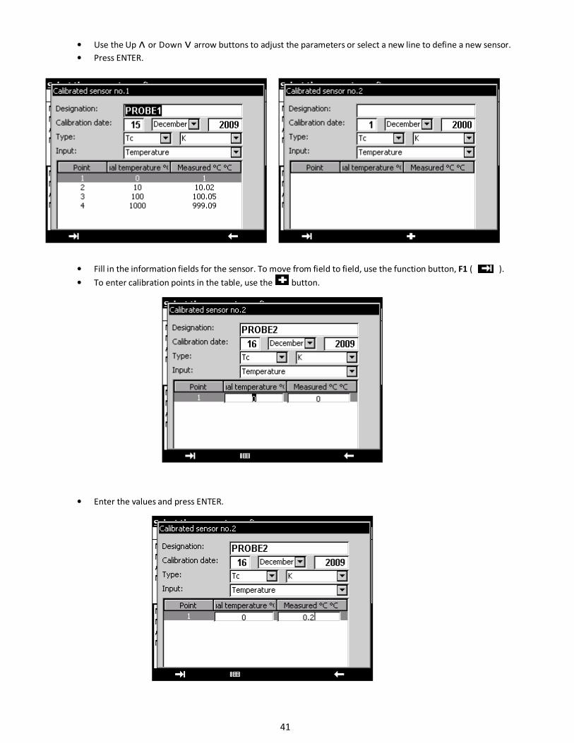
• Use the Up ᴧ or Down ᴠ arrow buttons to adjust the parameters or select a new line to define a new sensor.
• Press ENTER.
• Fill in the information fields for the sensor. To move from field to field, use the function button, F1 ( ).
• To enter calibration points in the table, use the button.
• Enter the values and press ENTER.
41
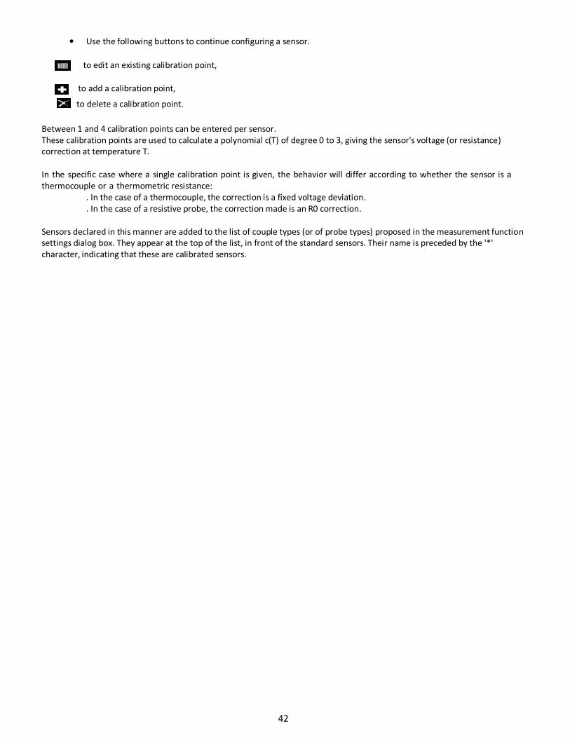
• Use the following buttons to continue configuring a sensor.
to edit an existing calibration point,
to add a calibration point,
to delete a calibration point.
Between 1 and 4 calibration points can be entered per sensor.
These calibration points are used to calculate a polynomial c(T) of degree 0 to 3, giving the sensor's voltage (or resistance)
correction at temperature T.
In the specific case where a single calibration point is given, the behavior will differ according to whether the sensor is a
thermocouple or a thermometric resistance:
. In the case of a thermocouple, the correction is a fixed voltage deviation.
. In the case of a resistive probe, the correction made is an R0 correction.
Sensors declared in this manner are added to the list of couple types (or of probe types) proposed in the measurement function
settings dialog box. They appear at the top of the list, in front of the standard sensors. Their name is preceded by the '*'
character, indicating that these are calibrated sensors.
42
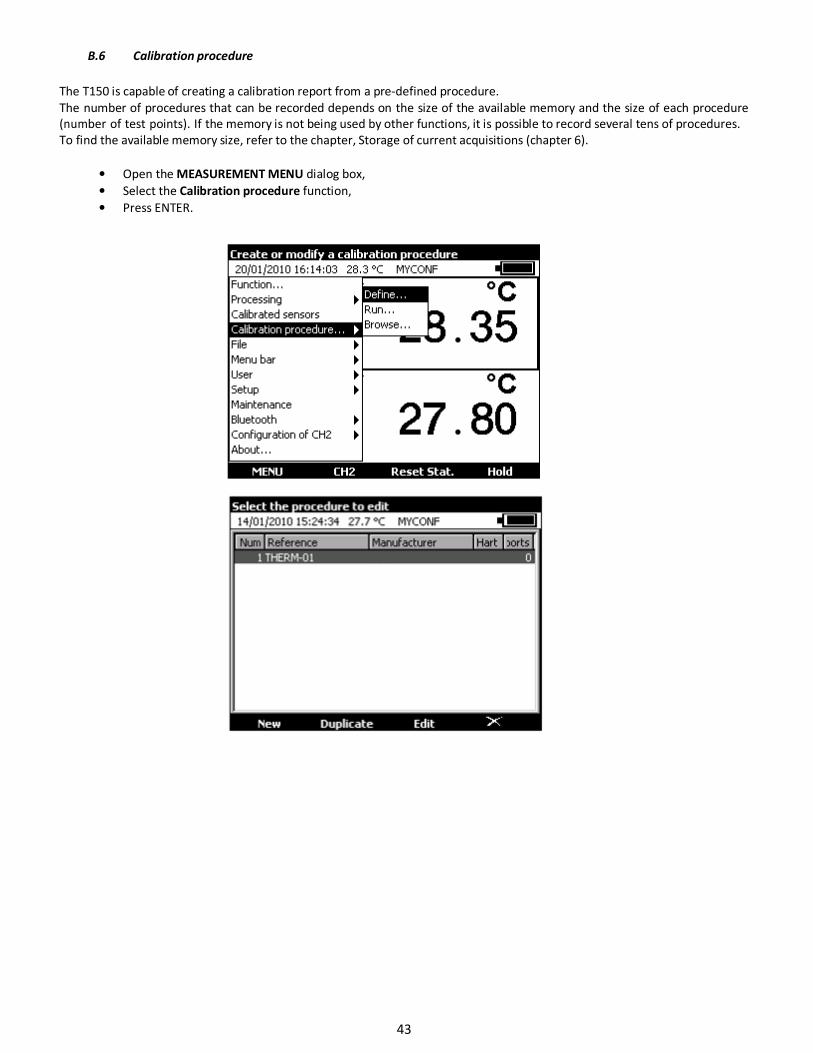
B.6 Calibration procedure
The T150 is capable of creating a calibration report from a pre-defined procedure.
The number of procedures that can be recorded depends on the size of the available memory and the size of each procedure
(number of test points). If the memory is not being used by other functions, it is possible to record several tens of procedures.
To find the available memory size, refer to the chapter, Storage of current acquisitions (chapter 6).
• Open the MEASUREMENT MENU dialog box,
• Select the Calibration procedure function,
• Press ENTER.
43
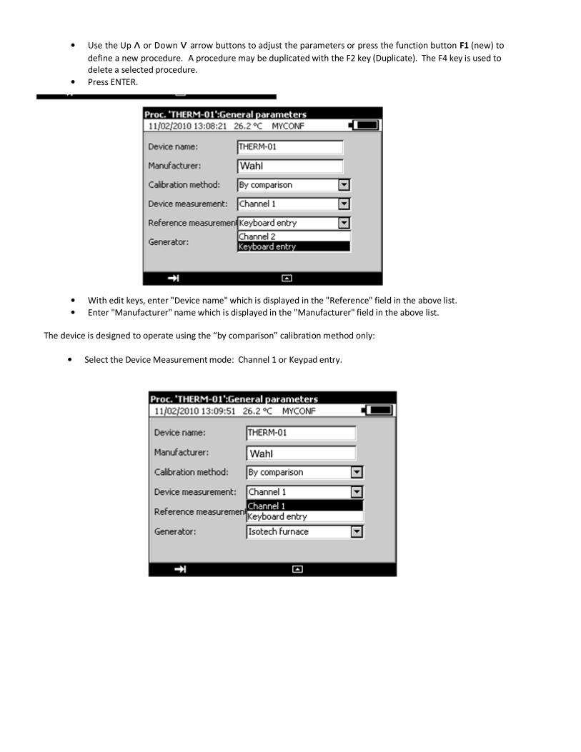
• Use the Up ᴧ or Down ᴠ arrow buttons to adjust the parameters or press the function button F1 (new) to
define a new procedure. A procedure may be duplicated with the F2 key (Duplicate). The F4 key is used to
delete a selected procedure.
• Press ENTER.
• With edit keys, enter "Device name" which is displayed in the "Reference" field in the above list.
• Enter "Manufacturer" name which is displayed in the "Manufacturer" field in the above list.
The device is designed to operate using the “by comparison” calibration method only:
• Select the Device Measurement mode: Channel 1 or Keypad entry.
44
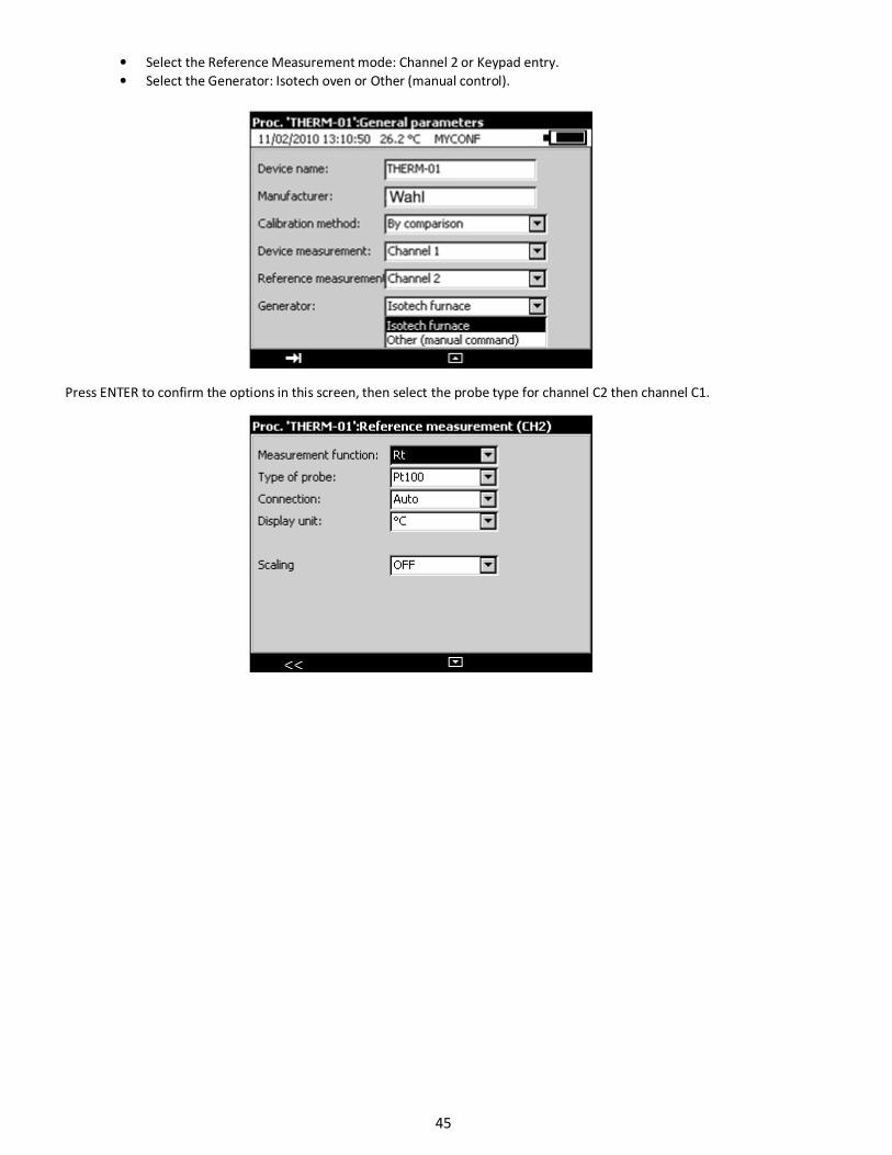
• Select the Reference Measurement mode: Channel 2 or Keypad entry.
• Select the Generator: Isotech oven or Other (manual control).
Press ENTER to confirm the options in this screen, then select the probe type for channel C2 then channel C1.
45
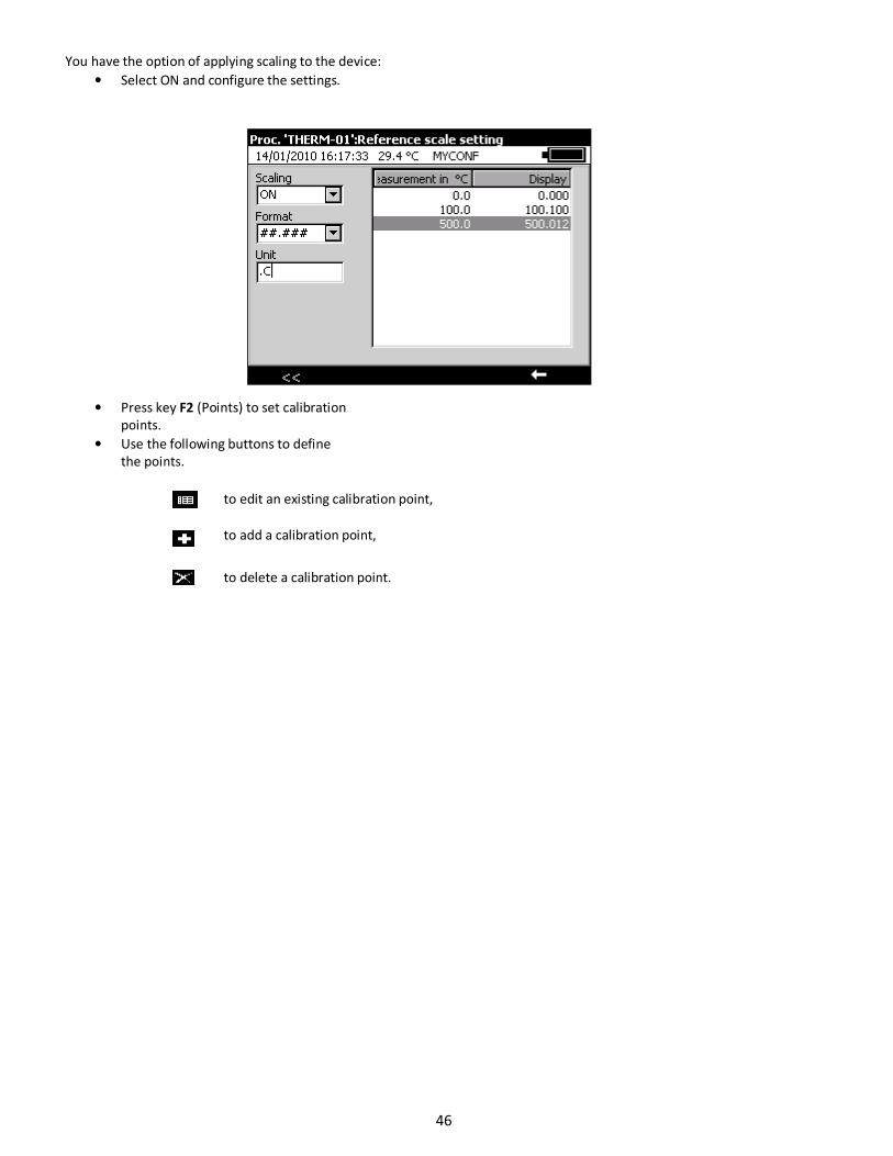
You have the option of applying scaling to the device:
• Select ON and configure the settings.
• Press key F2 (Points) to set calibration
points.
• Use the following buttons to define
the points.
to edit an existing calibration point,
to add a calibration point,
to delete a calibration point.
46
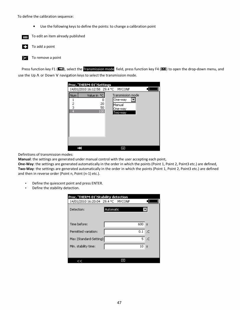
To define the calibration sequence:
• Use the following keys to define the points: to change a calibration point
To edit an item already published
To add a point
To remove a point
Press function key F1 ( ), select the Transmission mode field, press function key F4 ( ) to open the drop-down menu, and
use the Up ᴧ or Down ᴠ navigation keys to select the transmission mode.
Definitions of transmission modes:
Manual: the settings are generated under manual control with the user accepting each point,
One-Way: the settings are generated automatically in the order in which the points (Point 1, Point 2, Point3 etc.) are defined,
Two-Way: the settings are generated automatically in the order in which the points (Point 1, Point 2, Point3 etc.) are defined
and then in reverse order (Point n, Point (n-1) etc.).
Define the quiescent point and press ENTER.
Define the stability detection.
47
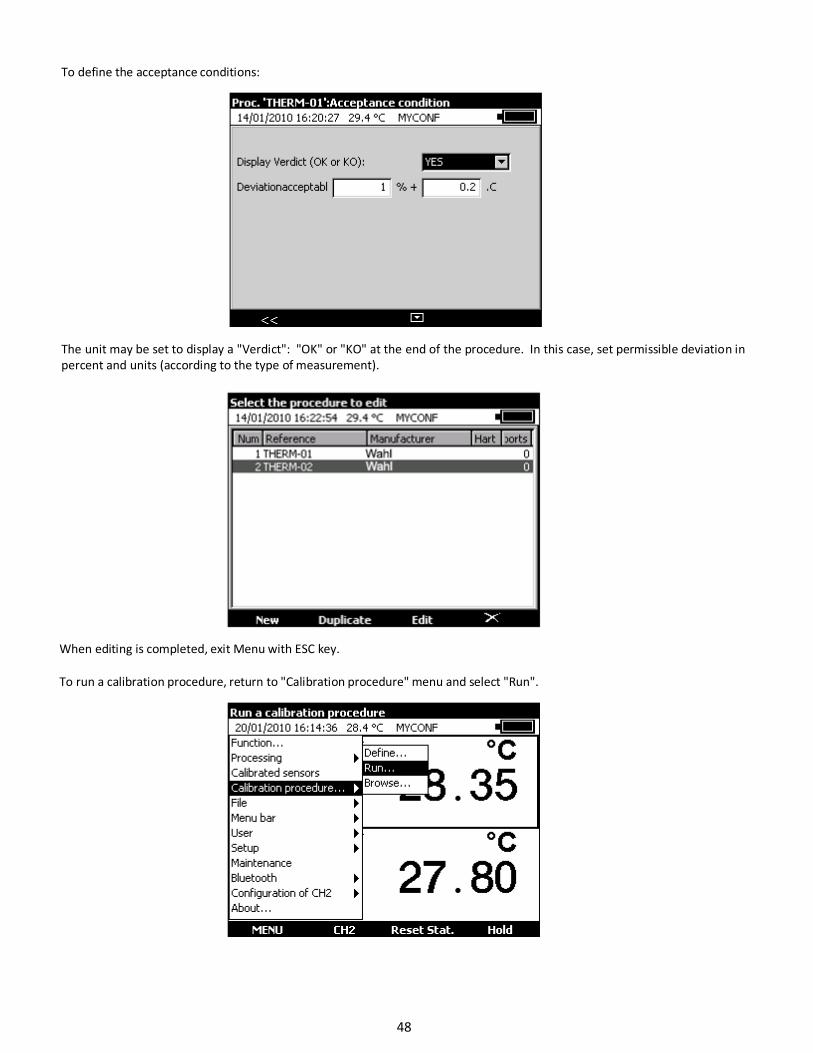
To define the acceptance conditions:
The unit may be set to display a "Verdict": "OK" or "KO" at the end of the procedure. In this case, set permissible deviation in
percent and units (according to the type of measurement).
When editing is completed, exit Menu with ESC key.
To run a calibration procedure, return to "Calibration procedure" menu and select "Run".
48
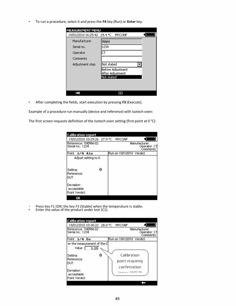
To run a procedure, select it and press the F4 key (Run) or Enter key.
After completing the fields, start execution by pressing F3 (Execute).
Example of a procedure run manually (device and reference) with Isotech oven:
The first screen requests definition of the Isotech oven setting (first point at 0 °C):
Press key F1 (OK) the key F3 (Stable) when the temperature is stable. Enter the value of the product under test (C1).
49
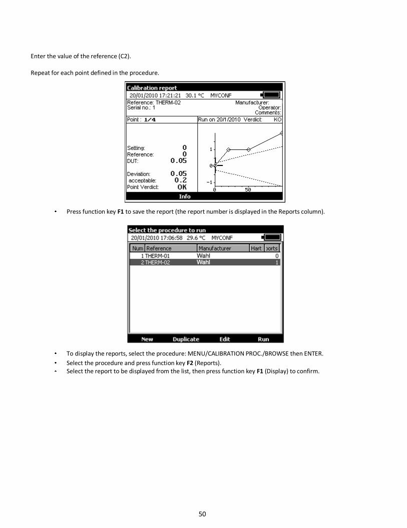
Enter the value of the reference (C2).
Repeat for each point defined in the procedure.
Press function key F1 to save the report (the report number is displayed in the Reports column).
To display the reports, select the procedure: MENU/CALIBRATION PROC./BROWSE then ENTER.
Select the procedure and press function key F2 (Reports).
Select the report to be displayed from the list, then press function key F1 (Display) to confirm.
50
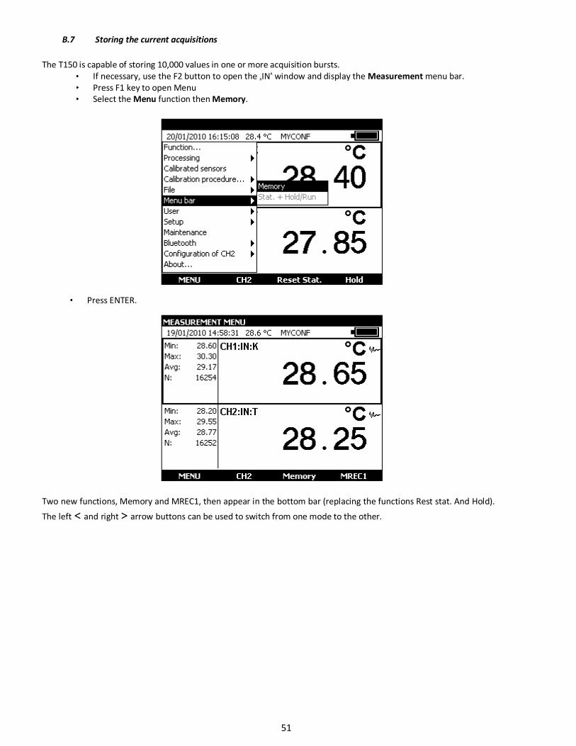
B.7 Storing the current acquisitions
The T150 is capable of storing 10,000 values in one or more acquisition bursts.
If necessary, use the F2 button to open the „IN‟ window and display the Measurement menu bar.
Press F1 key to open Menu
Select the Menu function then Memory.
Press ENTER.
Two new functions, Memory and MREC1, then appear in the bottom bar (replacing the functions Rest stat. And Hold).
The left ˂ and right ˃ arrow buttons can be used to switch from one mode to the other.
51
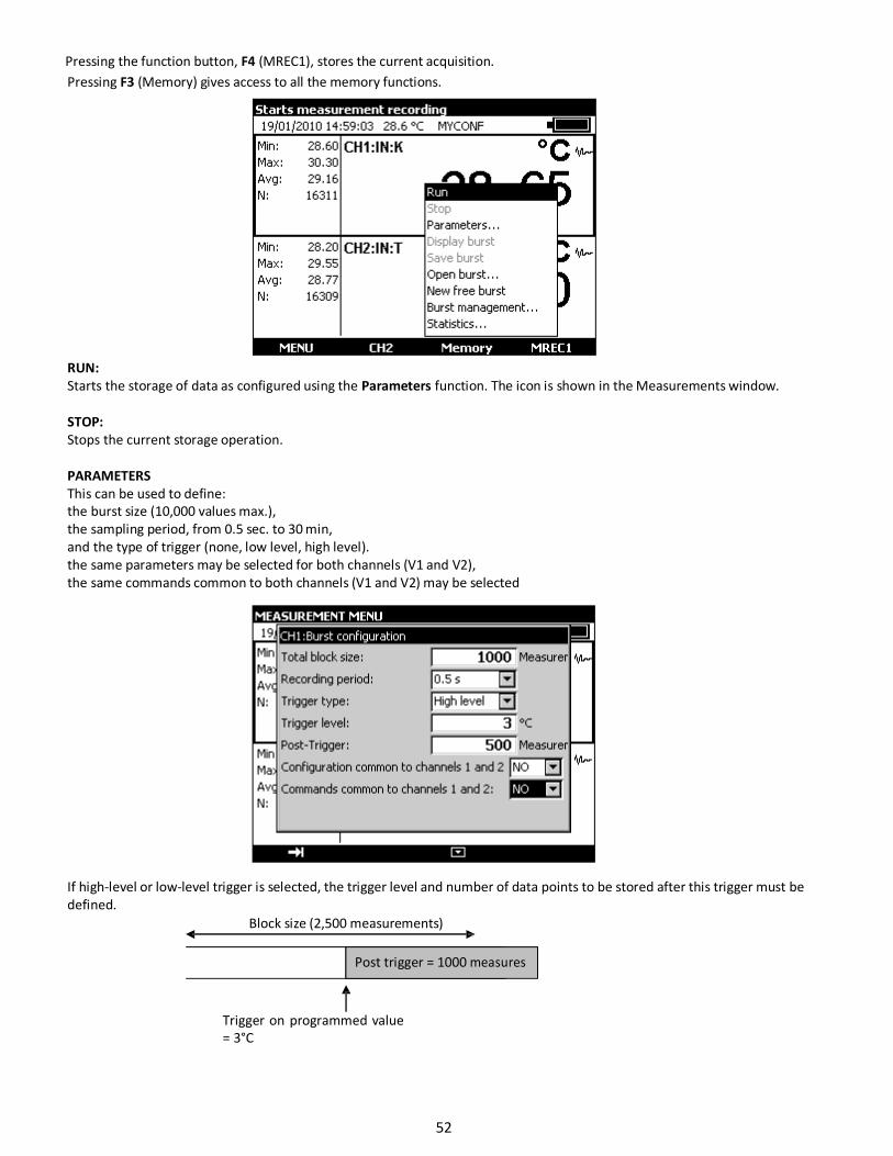
Pressing the function button, F4 (MREC1), stores the current acquisition.
Pressing F3 (Memory) gives access to all the memory functions.
RUN:
Starts the storage of data as configured using the Parameters function. The icon is shown in the Measurements window.
STOP:
Stops the current storage operation.
PARAMETERS
This can be used to define:
the burst size (10,000 values max.),
the sampling period, from 0.5 sec. to 30 min,
and the type of trigger (none, low level, high level).
the same parameters may be selected for both channels (V1 and V2),
the same commands common to both channels (V1 and V2) may be selected
If high-level or low-level trigger is selected, the trigger level and number of data points to be stored after this trigger must be
defined.
Block size (2,500 measurements)
Post trigger = 1000 measures
Trigger on programmed value
= 3°C
52
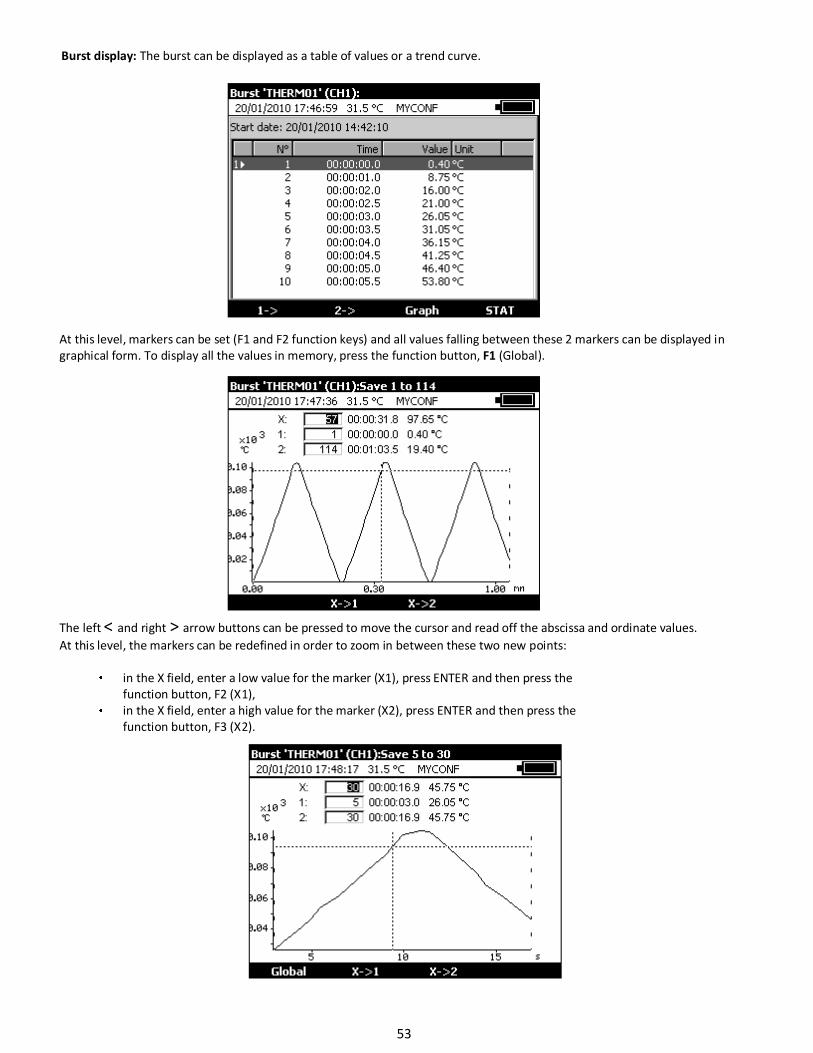
Burst display: The burst can be displayed as a table of values or a trend curve.
At this level, markers can be set (F1 and F2 function keys) and all values falling between these 2 markers can be displayed in
graphical form. To display all the values in memory, press the function button, F1 (Global).
The left ˂ and right ˃ arrow buttons can be pressed to move the cursor and read off the abscissa and ordinate values.
At this level, the markers can be redefined in order to zoom in between these two new points:
in the X field, enter a low value for the marker (X1), press ENTER and then press the
function button, F2 (X1),
in the X field, enter a high value for the marker (X2), press ENTER and then press the
function button, F3 (X2).
53
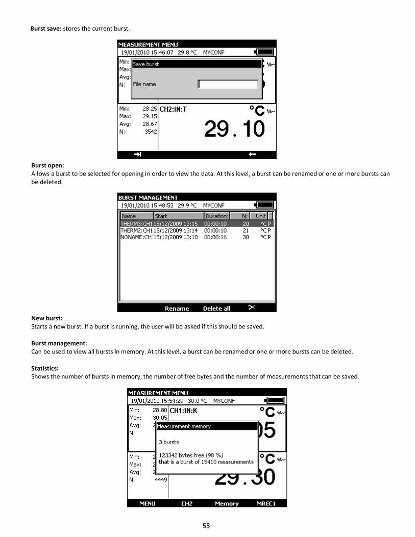
Burst save: stores the current burst.
Burst open:
Allows a burst to be selected for opening in order to view the data. At this level, a burst can be renamed or one or more bursts can
be deleted.
New burst:
Starts a new burst. If a burst is running, the user will be asked if this should be saved.
Burst management:
Can be used to view all bursts in memory. At this level, a burst can be renamed or one or more bursts can be deleted.
Statistics:
Shows the number of bursts in memory, the number of free bytes and the number of measurements that can be saved.
55
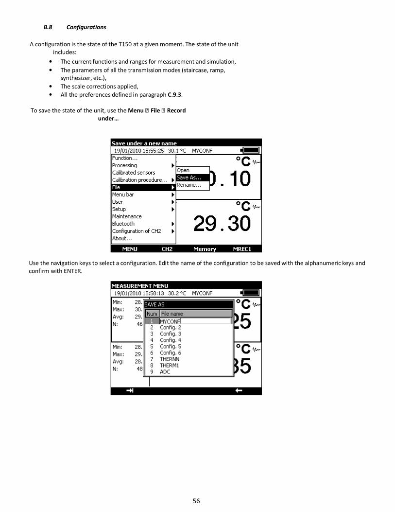
B.8 Configurations
A configuration is the state of the T150 at a given moment. The state of the unit
includes:
• The current functions and ranges for measurement and simulation,
• The parameters of all the transmission modes (staircase, ramp,
synthesizer, etc.),
• The scale corrections applied,
• All the preferences defined in paragraph C.9.3.
To save the state of the unit, use the Menu File Record
under…
Use the navigation keys to select a configuration. Edit the name of the configuration to be saved with the alphanumeric keys and
confirm with ENTER.
56
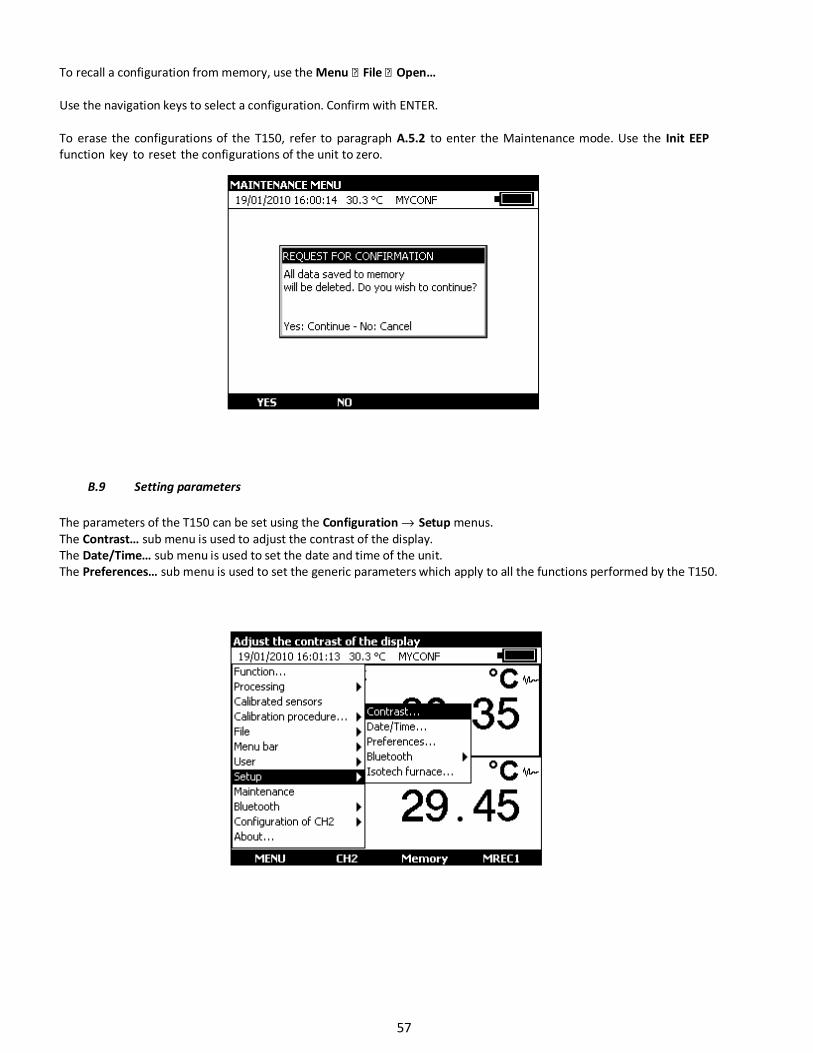
To recall a configuration from memory, use the Menu File Open…
Use the navigation keys to select a configuration. Confirm with ENTER.
To erase the configurations of the T150, refer to paragraph A.5.2 to enter the Maintenance mode. Use the Init EEP
function key to reset the configurations of the unit to zero.
B.9 Setting parameters
The parameters of the T150 can be set using the Configuration → Setup menus.
The Contrast… sub menu is used to adjust the contrast of the display.
The Date/Time… sub menu is used to set the date and time of the unit.
The Preferences… sub menu is used to set the generic parameters which apply to all the functions performed by the T150.
57
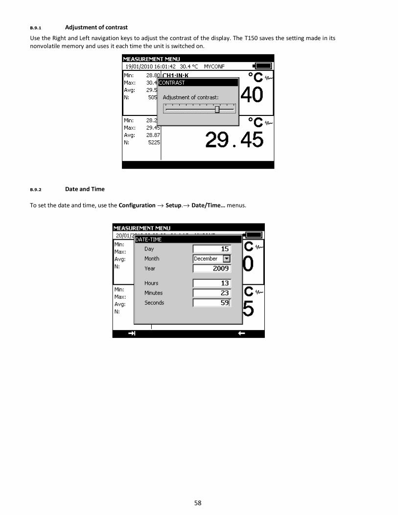
B.9.1 Adjustment of contrast
Use the Right and Left navigation keys to adjust the contrast of the display. The T150 saves the setting made in its
nonvolatile memory and uses it each time the unit is switched on.
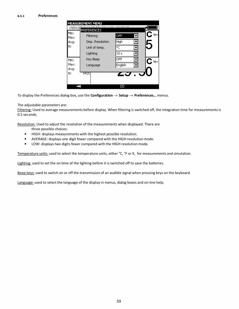
B.9.2 Date and Time
To set the date and time, use the Configuration → Setup.→ Date/Time… menus.
58
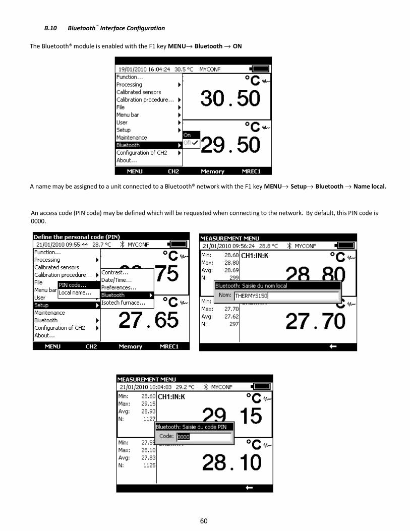
B.9.3 Preferences
To display the Preferences dialog box, use the Configuration → Setup → Preferences… menus.
The adjustable parameters are:
Filtering: Used to average measurements before display. When filtering is switched off, the integration time for measurements is
0.5 seconds.
Resolution: Used to adjust the resolution of the measurements when displayed. There are
three possible choices:
• HIGH: displays measurements with the highest possible resolution.
• AVERAGE: displays one digit fewer compared with the HIGH resolution mode.
• LOW: displays two digits fewer compared with the HIGH resolution mode.
Temperature units: used to select the temperature units, either °C, °F or K, for measurements and simulation.
Lighting: used to set the on time of the lighting before it is switched off to save the batteries.
Beep keys: used to switch on or off the transmission of an audible signal when pressing keys on the keyboard.
Language: used to select the language of the display in menus, dialog boxes and on-line help.
59
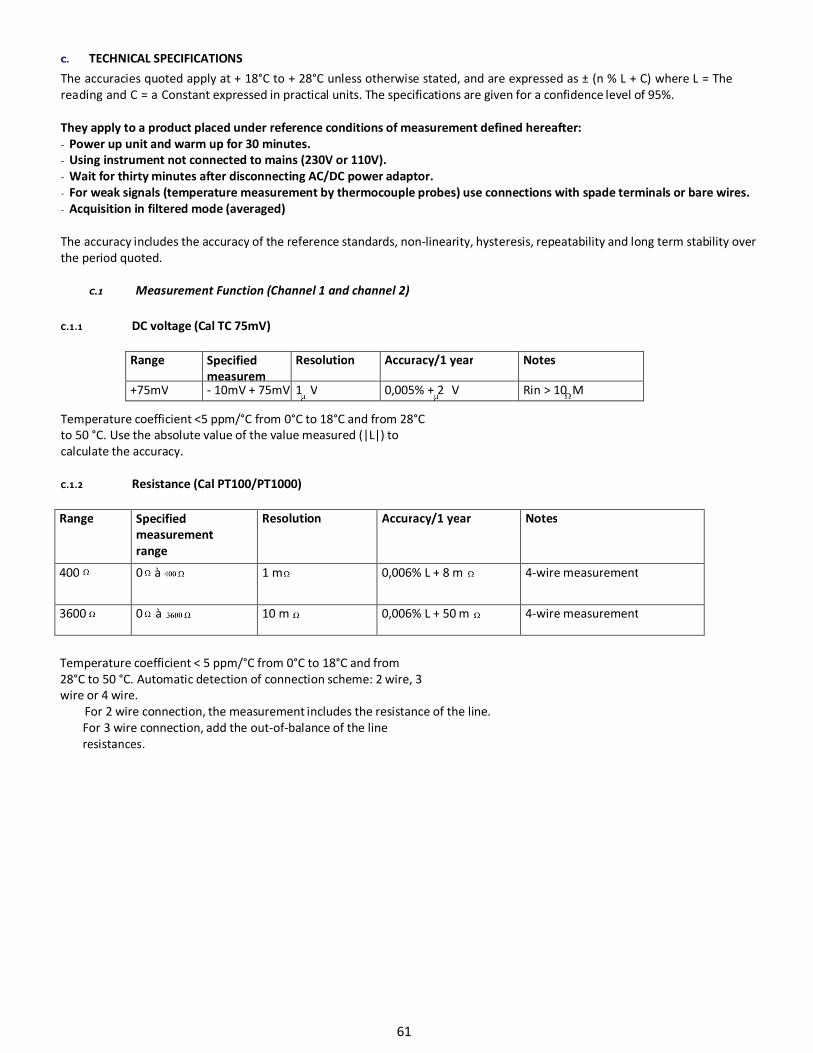
B.10 Bluetooth® Interface Configuration
The Bluetooth® module is enabled with the F1 key MENU→ Bluetooth → ON
A name may be assigned to a unit connected to a Bluetooth® network with the F1 key MENU→ Setup→ Bluetooth → Name local.
An access code (PIN code) may be defined which will be requested when connecting to the network. By default, this PIN code is
0000.
60
C. TECHNICAL SPECIFICATIONS
The accuracies quoted apply at + 18°C to + 28°C unless otherwise stated, and are expressed as ± (n % L + C) where L = The
reading and C = a Constant expressed in practical units. The specifications are given for a confidence level of 95%.
They apply to a product placed under reference conditions of measurement defined hereafter:
- Power up unit and warm up for 30 minutes.
- Using instrument not connected to mains (230V or 110V).
- Wait for thirty minutes after disconnecting AC/DC power adaptor.
- For weak signals (temperature measurement by thermocouple probes) use connections with spade terminals or bare wires.
- Acquisition in filtered mode (averaged)
The accuracy includes the accuracy of the reference standards, non-linearity, hysteresis, repeatability and long term stability over
the period quoted.
C.1 Measurement Function (Channel 1 and channel 2)
C.1.1 DC voltage (Cal TC 75mV)
Range Specified
measurem
Resolution Accuracy/1 year Notes
+75mV - 10mV + 75mV 1 V 0,005% + 2 V Rin > 10 M
Temperature coefficient <5 ppm/°C from 0°C to 18°C and from 28°C
to 50 °C. Use the absolute value of the value measured (|L|) to
calculate the accuracy.
C.1.2 Resistance (Cal PT100/PT1000)
Range Specified
measurement
range
Resolution Accuracy/1 year Notes
400 0 à 1 m 0,006% L + 8 m 4-wire measurement
3600 0 à 10 m 0,006% L + 50 m 4-wire measurement
Temperature coefficient < 5 ppm/°C from 0°C to 18°C and from
28°C to 50 °C. Automatic detection of connection scheme: 2 wire, 3
wire or 4 wire.
For 2 wire connection, the measurement includes the resistance of the line.
For 3 wire connection, add the out-of-balance of the line
resistances.
61
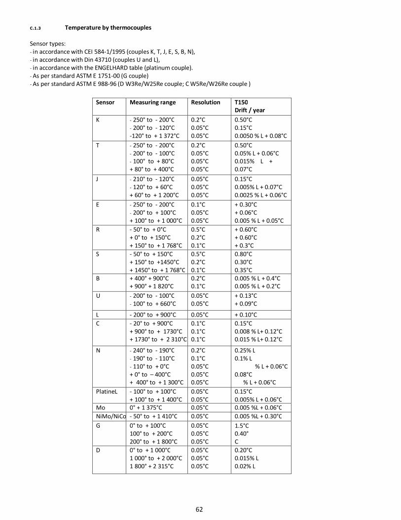
C.1.3 Temperature by thermocouples
Sensor types:
- in accordance with CEI 584-1/1995 (couples K, T, J, E, S, B, N),
- in accordance with Din 43710 (couples U and L),
- in accordance with the ENGELHARD table (platinum couple).
- As per standard ASTM E 1751-00 (G couple)
- As per standard ASTM E 988-96 (D W3Re/W25Re couple; C W5Re/W26Re couple )
Sensor Measuring range Resolution T150
Drift / year
K - 250° to - 200°C
- 200° to - 120°C
-120° to + 1 372°C
0.2°C
0.05°C
0.05°C
0.50°C
0.15°C
0.0050 % L + 0.08°C
T - 250° to - 200°C
- 200° to - 100°C
- 100° to + 80°C
+ 80° to + 400°C
0.2°C
0.05°C
0.05°C
0.05°C
0.50°C
0.05% L + 0.06°C
0.015% L +
0.07°C
0,06°C J - 210° to - 120°C
- 120° to + 60°C
+ 60° to + 1 200°C
0.05°C
0.05°C
0.05°C
0.15°C
0.005% L + 0.07°C
0.0025 % L + 0.06°C
E - 250° to - 200°C
- 200° to + 100°C
+ 100° to + 1 000°C
0.1°C
0.05°C
0.05°C
+ 0.30°C
+ 0.06°C
0.005 % L + 0.05°C
R - 50° to + 0°C
+ 0° to + 150°C
+ 150° to + 1 768°C
0.5°C
0.2°C
0.1°C
+ 0.60°C
+ 0.60°C
+ 0.3°C
S - 50° to + 150°C
+ 150° to +1450°C
+ 1450° to + 1 768°C
0.5°C
0.2°C
0.1°C
0.80°C
0.30°C
0.35°C
B + 400° + 900°C
+ 900° + 1 820°C
0.2°C
0.1°C
0.005 % L + 0.4°C
0.005 % L + 0.2°C
U - 200° to - 100°C
- 100° to + 660°C
0.05°C
0.05°C
+ 0.13°C
+ 0.09°C
L - 200° to + 900°C 0.05°C + 0.10°C
C - 20° to + 900°C
+ 900° to + 1730°C
+ 1730° to + 2 310°C
0.1°C
0.1°C
0.1°C
0.15°C
0.008 % L+ 0.12°C
0.015 % L+ 0.12°C
N - 240° to - 190°C
- 190° to - 110°C
- 110° to + 0°C
+ 0° to – 400°C
+ 400° to + 1 300°C
0.2°C
0.1°C
0.05°C
0.05°C
0.05°C
0.25% L
0.1% L
% L + 0.06°C
0.08°C
% L + 0.06°C
PlatineL - 100° to + 100°C
+ 100° to + 1 400°C
0.05°C
0.05°C
0.15°C
0.005% L + 0.06°C
Mo 0° + 1 375°C 0.05°C 0.005 %L + 0.06°C
NiMo/NiCo - 50° to + 1 410°C 0.05°C 0.005 %L + 0.30°C
G 0° to + 100°C
100° to + 200°C
200° to + 1 800°C
1 800 à + 2 315°C
0.05°C
0.05°C
0.05°C
0,05°C
1.5°C
0.40°
C
0.20°C D 0° to + 1 000°C
1 000° to + 2 000°C
1 800° + 2 315°C
0.05°C
0.05°C
0.05°C
0.20°C
0.015% L
0.02% L
62
The precision is guaranteed for a reference junction temperature of 0 °C.
When using the internal reference junction (except couple B) add an additional uncertainty of 0.2 °C at 0 °C. For other
temperatures, account must be taken of the sensitivity of the thermocouple to the temperature (T) in question, giving an
additional uncertainty of 0.2°C * S(0 °C)/ S(T).
• Temperature coefficient: < 10 % of
the accuracy/°C.
• Display in °C, °F and K.
• It is possible, thermocouple B excepted, to choose the location of the cold junction by programming from the
keyboard:
o external at 0°C,
o internal (compensation for the temperature of the terminals of the unit).
o by programming the temperature.
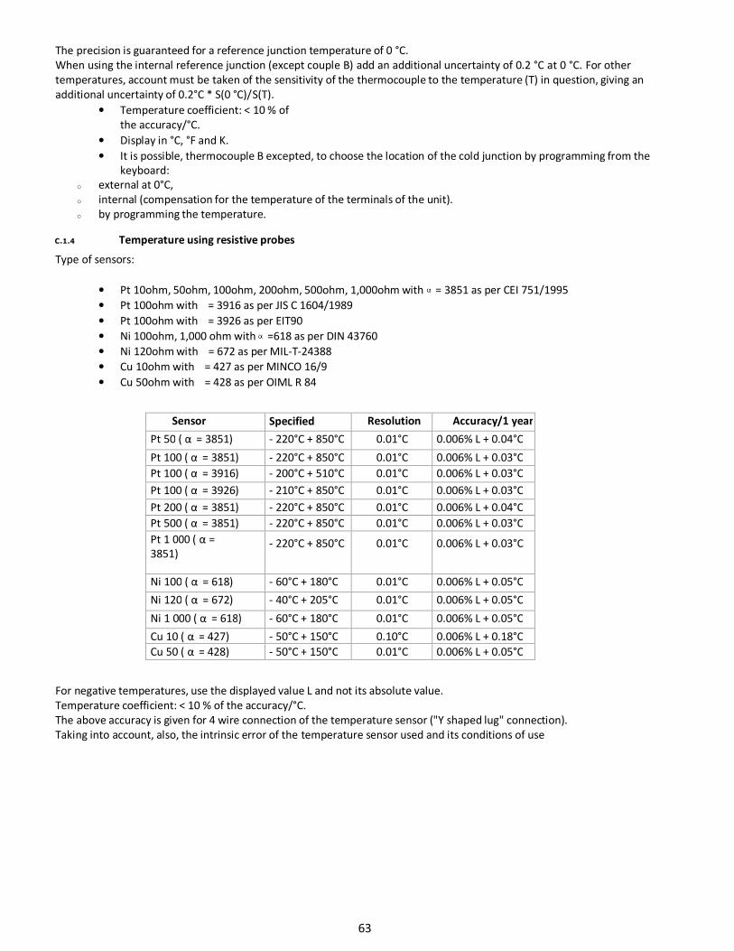
C.1.4 Temperature using resistive probes
Type of sensors:
• Pt 10ohm, 50ohm, 100ohm, 200ohm, 500ohm, 1,000ohm with = 3851 as per CEI 751/1995
• Pt 100ohm with = 3916 as per JIS C 1604/1989
• Pt 100ohm with = 3926 as per EIT90
• Ni 100ohm, 1,000 ohm with =618 as per DIN 43760
• Ni 120ohm with = 672 as per MIL-T-24388
• Cu 10ohm with = 427 as per MINCO 16/9
• Cu 50ohm with = 428 as per OIML R 84
Sensor Specified
measurement
Resolution Accuracy/1 year
Pt 50 ( α = 3851) - 220°C + 850°C 0.01°C 0.006% L + 0.04°C
Pt 100 ( α = 3851) - 220°C + 850°C 0.01°C 0.006% L + 0.03°C
Pt 100 ( α = 3916) - 200°C + 510°C 0.01°C 0.006% L + 0.03°C
Pt 100 ( α = 3926) - 210°C + 850°C 0.01°C 0.006% L + 0.03°C
Pt 200 ( α = 3851) - 220°C + 850°C 0.01°C 0.006% L + 0.04°C
Pt 500 ( α = 3851) - 220°C + 850°C 0.01°C 0.006% L + 0.03°C
Pt 1 000 ( α =
3851) - 220°C + 850°C 0.01°C 0.006% L + 0.03°C
Ni 100 ( α = 618) - 60°C + 180°C 0.01°C 0.006% L + 0.05°C
Ni 120 ( α = 672) - 40°C + 205°C 0.01°C 0.006% L + 0.05°C
Ni 1 000 ( α = 618) - 60°C + 180°C 0.01°C 0.006% L + 0.05°C
Cu 10 ( α = 427) - 50°C + 150°C 0.10°C 0.006% L + 0.18°C
Cu 50 ( α = 428) - 50°C + 150°C 0.01°C 0.006% L + 0.05°C
For negative temperatures, use the displayed value L and not its absolute value.
Temperature coefficient: < 10 % of the accuracy/°C.
The above accuracy is given for 4 wire connection of the temperature sensor ("Y shaped lug" connection).
Taking into account, also, the intrinsic error of the temperature sensor used and its conditions of use
63
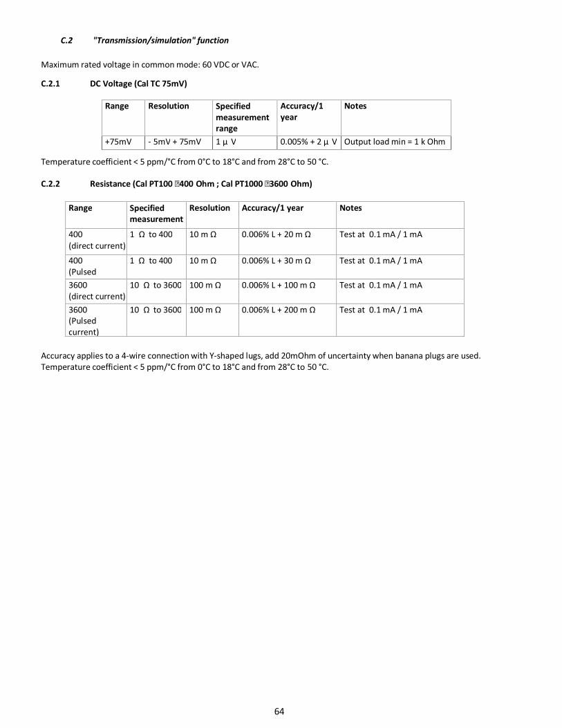
C.2 "Transmission/simulation" function
Maximum rated voltage in common mode: 60 VDC or VAC.
C.2.1 DC Voltage (Cal TC 75mV)
Range Resolution Specified
measurement
range
Accuracy/1
year
Notes
+75mV - 5mV + 75mV 1 µ V 0.005% + 2 µ V Output load min = 1 k Ohm
Temperature coefficient < 5 ppm/°C from 0°C to 18°C and from 28°C to 50 °C.
C.2.2 Resistance (Cal PT100 400 Ohm ; Cal PT1000 3600 Ohm)
Range Specified
measurement
range
Resolution Accuracy/1 year Notes
400
(direct current)
1 Ω to 400 10 m Ω 0.006% L + 20 m Ω Test at 0.1 mA / 1 mA
400
(Pulsed
current)
1 Ω to 400 10 m Ω 0.006% L + 30 m Ω Test at 0.1 mA / 1 mA
3600
(direct current)
10 Ω to 3600 100 m Ω 0.006% L + 100 m Ω Test at 0.1 mA / 1 mA
3600
(Pulsed
current)
10 Ω to 3600 100 m Ω 0.006% L + 200 m Ω Test at 0.1 mA / 1 mA
Accuracy applies to a 4-wire connection with Y-shaped lugs, add 20mOhm of uncertainty when banana plugs are used.
Temperature coefficient < 5 ppm/°C from 0°C to 18°C and from 28°C to 50 °C.
64
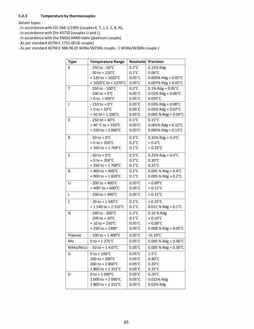
C.2.3 Temperature by thermocouples
Sensor types:
- in accordance with CEI 584-1/1995 (couples K, T, J, E, S, B, N),
- in accordance with Din 43710 (couples U and L),
- in accordance with the ENGELHARD table (platinum couple).
- As per standard ASTM E 1751-00 (G couple)
- As per standard ASTM E 988-96 (D W3Re/W25Re couple; C W5Re/W26Re couple )
Type Temperature Range Resolutio
n
Precision
K - 250 to - 50°C
- 50 to + 120°C
+ 120 to + 1020°C
+ 1020°C to + 1370°C
0.2°C
0.1°C
0.05°C
0.05°C
0.15% Rdg
0.06°C
0.005% Rdg + 0.05°C
0.007% Rdg + 0.05°C
T - 250 to - 100°C
- 100 to + 0°C
+ 0 to + 400°C
0.2°C
0.05°C
0.05°C
0.1% Rdg + 0.05°C
0.02% Rdg + 0.06°C
0.055°C
J - 210 to + 0°C
+ 0 to + 50°C
+ 50 to + 1 200°C
0.05°C
0.05°C
0.05°C
0.03% Rdg + 0.08°C
0.05% Rdg + 0.07°C
0.005 % Rdg + 0.04°C
E - 250 to + 40°C
+ 40 °C to + 550°C
+ 550 to + 1 000°C
0.1°C
0.05°C
0.05°C
0.15°C
0.005% Rdg + 0.12°C
0.005% Rdg + 0.13°C
R - 50 to + 0°C
+ 0 to + 350°C
+ 350 to + 1 768°C
0.5°C
0.2°C
0.1°C
0.35% Rdg + 0.4°C
+ 0.4°C
+ 0.25°C
S - 50 to + 0°C
+ 0 to + 350°C
+ 350 to + 1 768°C
0.5°C
0.2°C
0.1°C
0.25% Rdg + 0.4°C
0.30°C
0.25°C
B + 400 to + 900°C
+ 900 to + 1 820°C
0.2°C
0.1°C
0.005 % Rdg + 0.4°C
0.005 % Rdg + 0.2°C
U - 200 to + 400°C
+ 400° to + 600°C
0.05°C
0.05°C
+ 0.09°C
+ 0.11°C
L - 200 to + 900°C 0.05°C + 0.15°C
C - 20 to + 1 540°C
+ 1 540 to + 2 310°C
0.1°C
0.1°C
+ 0.25°C
0.012 % Rdg + 0.1°C
N - 240 to - 200°C
- 200 to + 10°C
+ 10 to + 250°C
+ 250 to + 1300°
0.2°C
0.1°C
0.05°C
0.05°C
0.15 % Rdg
+ 0,10°C
+ 0,08°C
0.008 % Rdg + 0.05°C
PlatineL - 100 to + 1 400°C 0.05°C +0.10°C
Mo 0 to + 1 375°C 0.05°C 0.005 % Rdg + 0.06°C
NiMo/NiCo - 50 to + 1 410°C 0.05°C 0.005 % Rdg + 0.30°C
G 0 to + 100°C
100 to + 200°C
200 to + 1 800°C
1 800 to + 2 315°C
0.05°C
0.05°C
0.05°C
0.05°C
1.5°C
0.40°C
0.20°C
0.35°C
D 0 to + 1 000°C
1 000 to + 2 000°C
1 800 to + 2 315°C
0.05°C
0.05°C
0.05°C
0.20°C
0.015% Rdg
0.02% Rdg
65
The precision is guaranteed for a reference junction temperature of 0 °C.
When using the internal reference junction (except couple B) add an additional uncertainty of 0.2 °C at 0 °C. For other
temperatures, account must be taken of the sensitivity of the thermocouple to the temperature (T) in question, giving an
additional uncertainty of 0.2 °C * S(0 °C)/ S(T).
• Temperature coefficient: < 10 % of the
accuracy/°C.
• Display in °C, °F and K.
• It is possible, thermocouple B excepted, to choose by programming the position of the cold junction with the
keyboard:
o external at 0°C,
o internal (compensation for the temperature of the terminals of the unit).
o by programming the temperature.
"Transmission/simulation" function
C
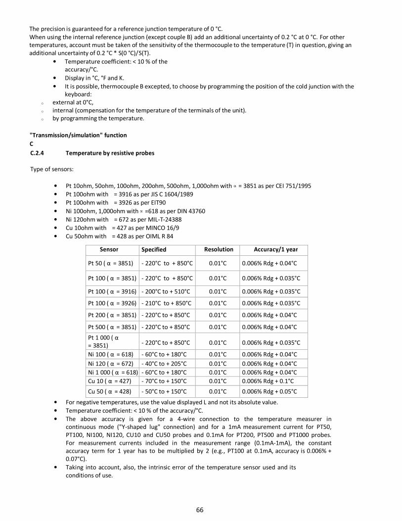
C.2.4 Temperature by resistive probes
Type of sensors:
• Pt 10ohm, 50ohm, 100ohm, 200ohm, 500ohm, 1,000ohm with = 3851 as per CEI 751/1995
• Pt 100ohm with = 3916 as per JIS C 1604/1989
• Pt 100ohm with = 3926 as per EIT90
• Ni 100ohm, 1,000ohm with =618 as per DIN 43760
• Ni 120ohm with = 672 as per MIL-T-24388
• Cu 10ohm with = 427 as per MINCO 16/9
• Cu 50ohm with = 428 as per OIML R 84
Sensor Specified
measurement
Resolution Accuracy/1 year
Pt 50 ( α = 3851) - 220°C to + 850°C 0.01°C 0.006% Rdg + 0.04°C
Pt 100 ( α = 3851) - 220°C to + 850°C 0.01°C 0.006% Rdg + 0.035°C
Pt 100 ( α = 3916) - 200°C to + 510°C 0.01°C 0.006% Rdg + 0.035°C
Pt 100 ( α = 3926) - 210°C to + 850°C 0.01°C 0.006% Rdg + 0.035°C
Pt 200 ( α = 3851) - 220°C to + 850°C 0.01°C 0.006% Rdg + 0.04°C
Pt 500 ( α = 3851) - 220°C to + 850°C 0.01°C 0.006% Rdg + 0.04°C
Pt 1 000 ( α
= 3851) - 220°C to + 850°C 0.01°C 0.006% Rdg + 0.035°C
Ni 100 ( α = 618) - 60°C to + 180°C 0.01°C 0.006% Rdg + 0.04°C
Ni 120 ( α = 672) - 40°C to + 205°C 0.01°C 0.006% Rdg + 0.04°C
Ni 1 000 ( α = 618) - 60°C to + 180°C 0.01°C 0.006% Rdg + 0.04°C
Cu 10 ( α = 427) - 70°C to + 150°C 0.01°C 0.006% Rdg + 0.1°C
Cu 50 ( α = 428) - 50°C to + 150°C 0.01°C 0.006% Rdg + 0.05°C
• For negative temperatures, use the value displayed L and not its absolute value.
• Temperature coefficient: < 10 % of the accuracy/°C.
• The above accuracy is given for a 4-wire connection to the temperature measurer in
continuous mode ("Y-shaped lug" connection) and for a 1mA measurement current for PT50,
PT100, NI100, NI120, CU10 and CU50 probes and 0.1mA for PT200, PT500 and PT1000 probes.
For measurement currents included in the measurement range (0.1mA-1mA), the constant
accuracy term for 1 year has to be multiplied by 2 (e.g., PT100 at 0.1mA, accuracy is 0.006% +
0.07°C).
• Taking into account, also, the intrinsic error of the temperature sensor used and its
conditions of use.
66

234 Old Weaverville Road
Asheville, NC 28804-1228
(800) 421-2853
(828) 658-0728
Email: [email protected]
www.palmerwahl.com