Embed Size (px)
Citation preview
36 Vol. 29 Issue 1, 2016
THEME ARTICLES
T.1: A Novel Technology for Niobium to Austenitic Stainless Steel Brazed Joints
1 2 2Abhay Kumar , P. Ganesh and Rakesh Kaul1Proton Linac & Superconducting Cavities Division2Laser Material Processing DivisionE mail: [email protected]
Abstract: Development of reliable Nb-316L stainless steel (SS) transition joints is an important step towards use of austenitic SS helium vessel for SRF cavities of particle accelerators. In this regard, a novel brazing recipe and a unique design for manufacture and assembly have been developed at RRCAT and the technology is standardized for producing defect-free, strong and ductile “Nb pipe/316L SS flange” brazed joint with repeatable joint characteristics. Important features of the development include (i) freedom from brittle intermetallic compounds, (ii) uniform and controlled joint thickness, (iii) efficient utilization of braze filler metal, (iv) simplified pre-braze fitting procedure,(v) environment friendly cleaning procedure and (vi) relaxed storage conditions for pre-braze assembly. The new technology marks significant improvement over existing global vacuum brazing practice in strength and ductility. Various aspects of the technology are discussed in this theme article.
1. IntroductionSuperconducting radio frequency (SRF) cavities are
being employed for energizing charged particles in particle accelerators to avail advantages like less power dissipation on the cavity wall and higher beam current [1,2]. SRF cavity is the only viable choice for the high energy and high current particle accelerators operating in continuous wave mode or pulsed mode with high duty factor. Niobium has the highest critical temperature in pure metals together with highest value of lower critical magnetic field among all known superconductors. Niobium also has good weldability and excellent room temperature ductility for facilitating forming. Its thermal conductivity can be improved by decreasing the impurities. It has adequate strength and elastic modulus to bear the operating and the test conditions. The unique combination of these properties makes niobium the only choice for making SRF cavities, even where new thin film deposition options (Nb Sn, MgB , NbN or SIS multilayer) are 3 2
being explored.
The niobium SRF cavities are submerged in liquid helium at 2K during operation for limiting the losses, efficient heat removal and stable operation. The tank, housing the cavity, is called helium vessel. Titanium, because of the proximity of its coefficient of thermal expansion (CTE) with
niobium (α /α ≈ 1.2), is a natural choice for the material of Ti Nb
construction of helium vessel. Fabrication of titanium vessel is a specialized job due to the extreme reactivity of titanium during welding. The development of austenitic stainless steel (SS) helium vessel has the potential of reducing its cost to nearly one tenth of that of the titanium vessel due to lower material cost and simpler and well-established fabrication technology. Availability of indigenous SS material and its matured welding technology make this choice more industry friendly as compared to titanium. Selection of austenitic SS (a/a ≈ 2.5) as helium vessel material faces some 316LSS Nb
complexities related to design and fabrication; the latter one is particularly significant as niobium and SS cannot be joined by fusion welding techniques.
Solid-state joining processes like diffusion bonding and explosion bonding have been developed to join niobium with austenitic SS. Vacuum brazing technique was also developed. Some non-elliptic SRF cavities, with austenitic SS helium vessels, are successfully operating in many accelerators. Recently, serious attempts are being made to develop austenitic SS vessels for elliptic cavities also by implementing a pre-stress during cool down to circumvent the effect of differential contraction. In most of the SS helium vessels, the transition joint between niobium and SS is made by brazing. This recipe was developed by CERN in 1987 and was perfected into a technology for making a pipe to flange joint at ANL in 2003 [3,4]. The brazing recipe utilizes oxygen free electronic (OFE) copper as braze filler metal (BFM). The joint qualifies against the operating conditions but displays completely brittle fracture in tensile/shear testing due to the formation of a layer of brittle intermetallic compounds of niobium with iron, chromium and nickel. Also, there is a significant penetration of copper along SS grain boundaries.
In this respect, efforts to develop a new indigenous brazing technology at RRCAT were formulated in two steps, viz. (i) development of brazing recipe to yield defect-free, ductile and strong Nb/austenitic SS brazed joints that are free of brittle Nb-Fe intermetallic compound and (ii) development of technology to produce these joints in large numbers with repeatable characteristics. The first part primarily focused on finding suitable approach to eliminate brittle intermetallic compounds in the brazed joint. On the other hand, the second part mainly involved efforts to fix joint thickness and obtain its uniformity in circumferential and longitudinal directions in the brazed pipe-flange assembly through a design for manufacture and assembly (DFMA).
2. Development of brazing recipeTwo-pronged approach adopted to suppress
intermetallic formation involved (i) reducing brazing temperature by using a low temperature BFM and (ii)
37 Vol. 29 Issue 1, 2016
THEME ARTICLES
providing a diffusion barrier on faying surface of the 316L SS flange.
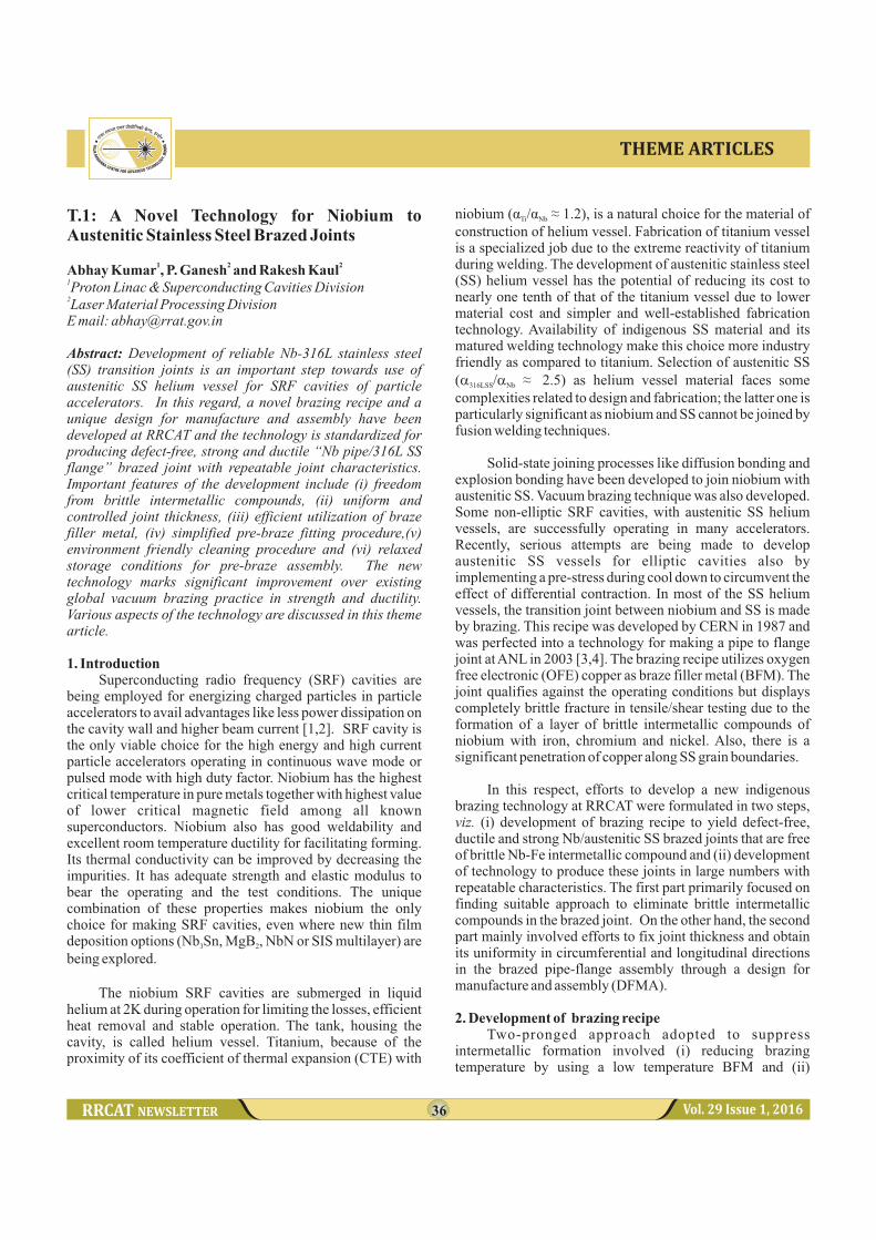
Fig. T.1.1: Details of vacuum brazed niobium-316L SS specimens used for the study.
TM2.1. Brazing with CuSil-ABA braze filler metal
Niobium surface suffers from poor wettability as it quickly develops adherent oxide film at room-temperature (RT) in ambient atmosphere [5]. In 2005, D. W. Liaw et al [6] reported that during brazing Ti dissolution into Ag-Cu BFM effectively improves its wetting on Nb surface. The results pointed towards the possibility of using Ti-activated Ag-brazing alloys for obtaining Nb/316L SS brazed joints. It has been reported that active metal modifications of Ag-Cu eutectic BFM may be useful for brazing niobium, particularly if residual oxide on the surface presents a wetting problem [7]. Chuang et al [8] reported sound Nb/Mo brazed joints with two different active Ag-based BFMs (63Ag/35.25Cu/1.75Ti and 68.8Ag/26.7Cu/4.5Ti). Brazed joints displayed excellent wetting of Mo & Nb with no reaction product at Nb/braze &
TMMo/braze interfaces. On this basis, CuSil-ABA (63Ag/35.25Cu/1.75Ti; melting range: 1053 - 1088 K) was selected as BFM for experimental investigations. On the other hand, while considering diffusion barrier to prevent Fe diffusion towards niobium, it may be noted that nickel plating has been extensively used in brazing technique to improve wettability and adhesion [9-11] at temperatures below 1123K. Hence, the study used 2 -3 µm thick nickel electroplating on austenitic SS part as a diffusion barrier to suppress migration of Fe towards Nb, besides preventing intergranular penetration of copper into austenitic SS.
The specimens used for the brazing study included (i) brazed Nb-316L SS tensile and shear test specimens in sandwich configuration using 50 µm thick BFM foil and (ii) capillary joint of Nb pipe-nickel plated 316L SS flange brazed with 1 mm dia BFM wire for conducting helium leak tests (HLT), as shown in Fig.T.1.1.
In addition to HLT, pipe-flange brazed assembly was also qualified with respect to its capability to withstand hydrogen degassing treatment (873K/10 hrs) and
testing/service-induced low cycle fatigue (LCF) conditions involving thermal cycling between room temperature (RT) and liquid helium temperature (LHeT). The degassing treatment at 873 K is recommended for niobium cavities to drive out hydrogen contamination [12] which is responsible for “Q-disease” [13]. It may be noted that most of materials' contraction occur between RT and liquid nitrogen temperature (LN T, 77K). Hence, during initial part of the 2
study, thermal cycling conditions used for qualification of the transition joint involved cycling between RT and LN T in 2
place of LHeT which provided preliminary validation of the reliability of Nb/austenitic SS transition joints against service-induced LCF conditions.
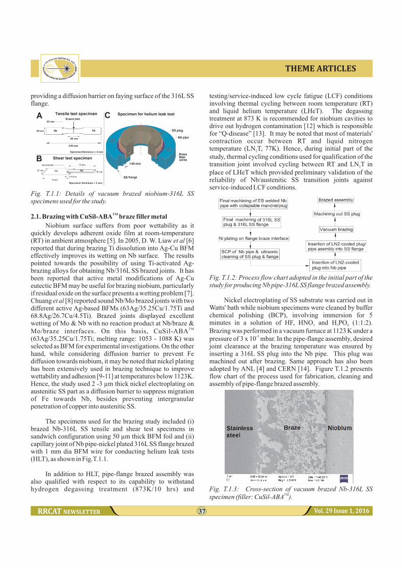
Fig. T.1.2: Process flow chart adopted in the initial part of the study for producing Nb pipe-316L SS flange brazed assembly.
Nickel electroplating of SS substrate was carried out in Watts' bath while niobium specimens were cleaned by buffer chemical polishing (BCP), involving immersion for 5 minutes in a solution of HF, HNO and H PO (1:1:2). 3 3 4
Brazing was performed in a vacuum furnace at 1123 K under a -5pressure of 3 x 10 mbar. In the pipe-flange assembly, desired
joint clearance at the brazing temperature was ensured by inserting a 316L SS plug into the Nb pipe. This plug was machined out after brazing. Same approach has also been adopted by ANL [4] and CERN [14]. Figure T.1.2 presents flow chart of the process used for fabrication, cleaning and assembly of pipe-flange brazed assembly.
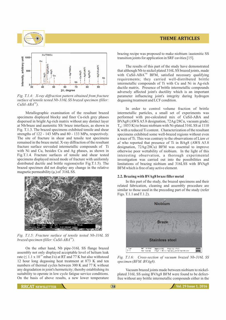
Fig. T.1.3: Cross-section of vacuum brazed Nb-316L SS TMspecimen (filler: CuSil-ABA ).
38 Vol. 29 Issue 1, 2016
THEME ARTICLES
Fig. T.1.4: X-ray diffraction pattern obtained from fracture surface of tensile tested Nb-316L SS brazed specimen (filler:
TMCuSil-ABA ).
Metallographic examination of the resultant brazed specimens displayed blocky and finer Cu-rich grey phases dispersed in bright Ag-rich matrix without any distinct layer at Nb/braze and austenitic SS/ braze interfaces, as shown in Fig. T.1.3. The brazed specimens exhibited tensile and shear strengths of 122 - 143 MPa and 80 - 133 MPa, respectively. The site of fracture in shear and tensile test specimens remained in the braze metal. X-ray diffraction of the resultant fracture surface srevealed intermetallic compounds of Ti with Ni and Cu, besides Cu and Ag phases, as shown in Fig.T.1.4. Fracture surfaces of tensile and shear tested specimens displayed mixed mode of fracture with uniformly distributed ductile and brittle regions(refer Fig.T.1.5). The brazed specimen did not display any change in the relative magnetic permeability (µ ) of 316L SS.r
Fig. T.1.5: Fracture surface of tensile tested Nb-316L SS TMbrazed specimen (filler: CuSil-ABA ).
On the other hand, Nb pipe-316L SS flange brazed assembly not only displayed acceptable level of helium leak
-10rate (≤ 1.1 x 10 mbar.l/s) at RT and 77 K but also withstood 12 hour long degassing heat treatment at 873 K and ten numbers of thermal cycles between 300 K and 77 K without any degradation in joint's hermeticity; thereby establishing its suitability to operate in low cycle fatigue service conditions. On the basis of above results, a new lower temperature
brazing recipe was proposed to make niobium /austenitic SS transition joints for application in SRF cavities [15].
The results of this part of the study have demonstrated that although Nb to nickel plated 316L SS brazed joints, made
TMwith CuSil-ABA BFM, satisfied necessary qualifying requirements; they carried well-distributed brittle intermetallic compounds of Ti with Cu and Ni in Ag-rich ductile matrix. Presence of brittle intermetallic compounds adversely affected joint's ductility which is an important parameter influencing joint's integrity during hydrogen degassing treatment and LCF condition.
In order to control volume fraction of brittle intermetallic particles, a small set of experiments was performed with pre-calculated mix of CuSil-ABA and BVAg8 (AWS A5.8 designation, 72Ag/28Cu, vacuum grade; T : 1053 K) to braze niobium with Ni-plated 316L SS at 1110 M
K with a reduced Ti content. Characterization of the resultant specimens exhibited some well-brazed regions without even a trace of Ti. This was contrary to the observations of Liaw et al who reported that presence of Ti in BAg8 (AWS A5.8 designation, 72Ag/28Cu) BFM was essential to improve otherwise poor wettability of niobium. In the light of this interesting observation, a thorough experimental investigation was carried out into the possibilities and limitations of brazing niobium and 316LSS with BVAg8 BFM which is free of any active element.
2.2. Brazing with BVAg8 braze filler metal
In this part of the study, the brazed specimens and their related fabrication, cleaning and assembly procedure are similar to those used in the preceding part of the study (refer Figs. T.1.1 and T.1.2).
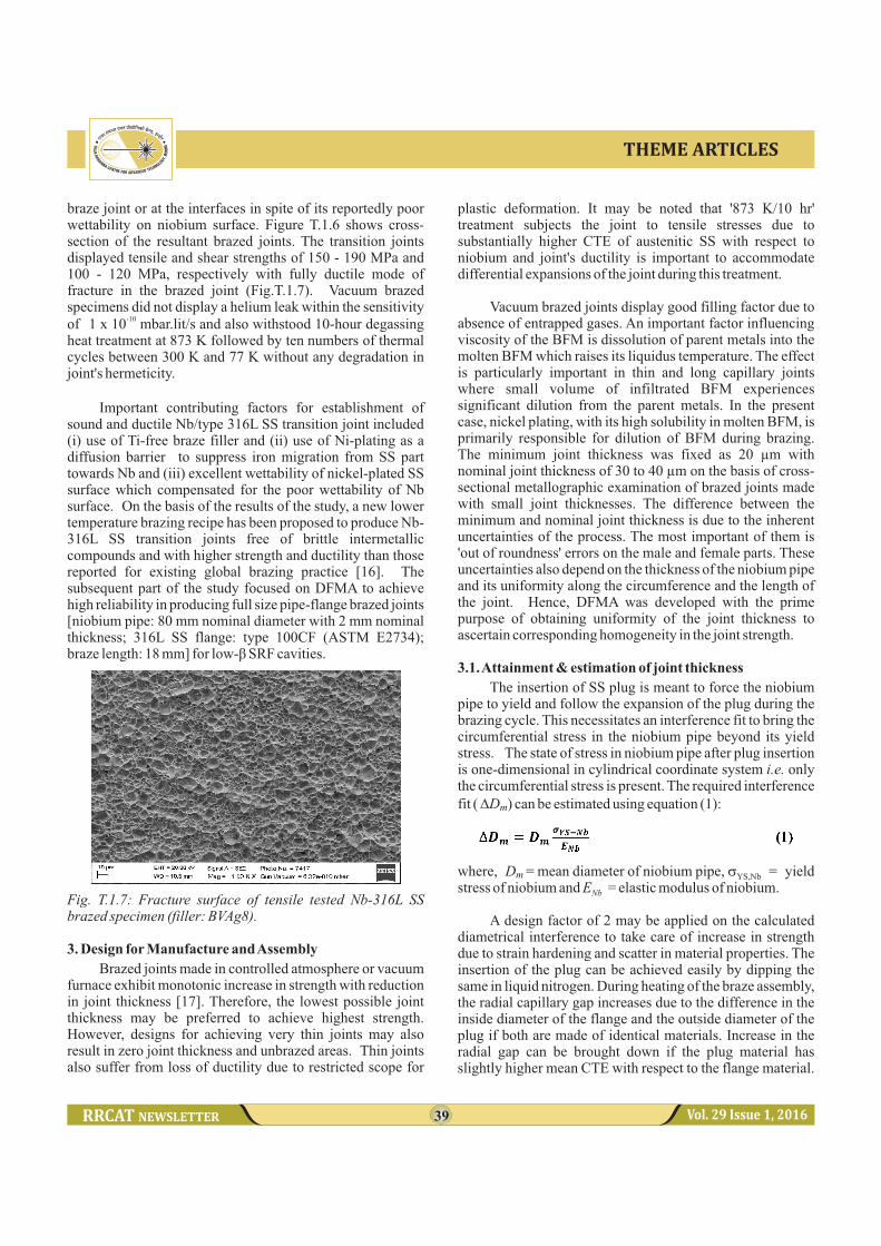
Fig. T.1.6: Cross-section of vacuum brazed Nb-316L SS specimen (BFM: BVAg8).
Vacuum brazed joints made between niobium to nickel-plated 316L SS using BVAg8 BFM were found to be defect-free without any brittle intermetallic compounds either in the
39 Vol. 29 Issue 1, 2016
THEME ARTICLES
braze joint or at the interfaces in spite of its reportedly poor wettability on niobium surface. Figure T.1.6 shows cross-section of the resultant brazed joints. The transition joints displayed tensile and shear strengths of 150 - 190 MPa and 100 - 120 MPa, respectively with fully ductile mode of fracture in the brazed joint (Fig.T.1.7). Vacuum brazed specimens did not display a helium leak within the sensitivity
-10of 1 x 10 mbar.lit/s and also withstood 10-hour degassing heat treatment at 873 K followed by ten numbers of thermal cycles between 300 K and 77 K without any degradation in joint's hermeticity.
Important contributing factors for establishment of sound and ductile Nb/type 316L SS transition joint included (i) use of Ti-free braze filler and (ii) use of Ni-plating as a diffusion barrier to suppress iron migration from SS part towards Nb and (iii) excellent wettability of nickel-plated SS surface which compensated for the poor wettability of Nb surface. On the basis of the results of the study, a new lower temperature brazing recipe has been proposed to produce Nb-316L SS transition joints free of brittle intermetallic compounds and with higher strength and ductility than those reported for existing global brazing practice [16]. The subsequent part of the study focused on DFMA to achieve high reliability in producing full size pipe-flange brazed joints [niobium pipe: 80 mm nominal diameter with 2 mm nominal thickness; 316L SS flange: type 100CF (ASTM E2734); braze length: 18 mm] for low-β SRF cavities.
Fig. T.1.7: Fracture surface of tensile tested Nb-316L SS brazed specimen (filler: BVAg8).
3. Design for Manufacture and Assembly
Brazed joints made in controlled atmosphere or vacuum furnace exhibit monotonic increase in strength with reduction in joint thickness [17]. Therefore, the lowest possible joint thickness may be preferred to achieve highest strength. However, designs for achieving very thin joints may also result in zero joint thickness and unbrazed areas. Thin joints also suffer from loss of ductility due to restricted scope for
plastic deformation. It may be noted that '873 K/10 hr' treatment subjects the joint to tensile stresses due to substantially higher CTE of austenitic SS with respect to niobium and joint's ductility is important to accommodate differential expansions of the joint during this treatment.
Vacuum brazed joints display good filling factor due to absence of entrapped gases. An important factor influencing viscosity of the BFM is dissolution of parent metals into the molten BFM which raises its liquidus temperature. The effect is particularly important in thin and long capillary joints where small volume of infiltrated BFM experiences significant dilution from the parent metals. In the present case, nickel plating, with its high solubility in molten BFM, is primarily responsible for dilution of BFM during brazing. The minimum joint thickness was fixed as 20 µm with nominal joint thickness of 30 to 40 µm on the basis of cross-sectional metallographic examination of brazed joints made with small joint thicknesses. The difference between the minimum and nominal joint thickness is due to the inherent uncertainties of the process. The most important of them is 'out of roundness' errors on the male and female parts. These uncertainties also depend on the thickness of the niobium pipe and its uniformity along the circumference and the length of the joint. Hence, DFMA was developed with the prime purpose of obtaining uniformity of the joint thickness to ascertain corresponding homogeneity in the joint strength.
3.1. Attainment & estimation of joint thickness
The insertion of SS plug is meant to force the niobium pipe to yield and follow the expansion of the plug during the brazing cycle. This necessitates an interference fit to bring the circumferential stress in the niobium pipe beyond its yield stress. The state of stress in niobium pipe after plug insertion is one-dimensional in cylindrical coordinate system i.e. only the circumferential stress is present. The required interference fit ( DD ) can be estimated using equation (1):
where, D = mean diameter of niobium pipe, s = yield m
stress of niobium and E = elastic modulus of niobium.Nb
A design factor of 2 may be applied on the calculated diametrical interference to take care of increase in strength due to strain hardening and scatter in material properties. The insertion of the plug can be achieved easily by dipping the same in liquid nitrogen. During heating of the braze assembly, the radial capillary gap increases due to the difference in the inside diameter of the flange and the outside diameter of the plug if both are made of identical materials. Increase in the radial gap can be brought down if the plug material has slightly higher mean CTE with respect to the flange material.
m
YS,Nb
40 Vol. 29 Issue 1, 2016
THEME ARTICLES
304 SS has a mean CTE of 19.5 m/m.K (293K - 1073 K) which is slightly higher than that of 316 SS (19.0 mm/m.K). Hence, the material of sacrificial plug has been changed to 304 SS in the new design for better control of capillary gap at the brazing temperature. Another major advantage offered by the use of sacrificial plug of 304 SS (in place of 316L SS) is that it could facilitate clearance fit assembly of Nb pipe/SS plug assembly into SS flange, thereby eliminating the requirement of shrink fitting/press fitting - a procedure followed in the initial part of the study (refer Fig. T.1.2).
The important factors controlling joint gap at brazing temperature are: (i) G: radial gap between faying surfaces at RT in the pre-braze assembly, (ii) ΔG :change in the radial FP
gap during heating due to differential thermal expansion of inside diameter of the flange (Di ) and outside diameter of the F
plug (Do ) (iii) ΔG : change in the radial gap during heating P P
due to the plastic thinning of the niobium pipe and (iv) ΔG : Nb
change in the radial gap during the heating due to thermal expansion of niobium pipe. ΔG can be estimated using FP
equation (2):
where, a = mean CTE of 316SS, a = mean CTE of 316
304SS and ΔT = brazing temperature - RT
Volume of the niobium tube remains constant during its plastic deformation brought by the thermal expansion of the SS plug. Expansion of the plug does not change the length of the niobium pipe as the plug is free to slide longitudinally inside the pipe if the limiting frictional force is ignored. Therefore, the condition of constancy of the cross-sectional area can be applied:
Where d and dare the mean diameter and the thickness of i Nb
niobium pipe respectively at the beginning of heating cycle; and d and d are mean diameter and thickness of niobium f f
pipe respectively at the brazing temperature.
For a thin pipe, the mean diameter can be replaced with internal diameter without inviting much error. Therefore;
m
304
The thermal expansion of niobium pipe thickness can be estimated as:
dNb
aNb
djoint
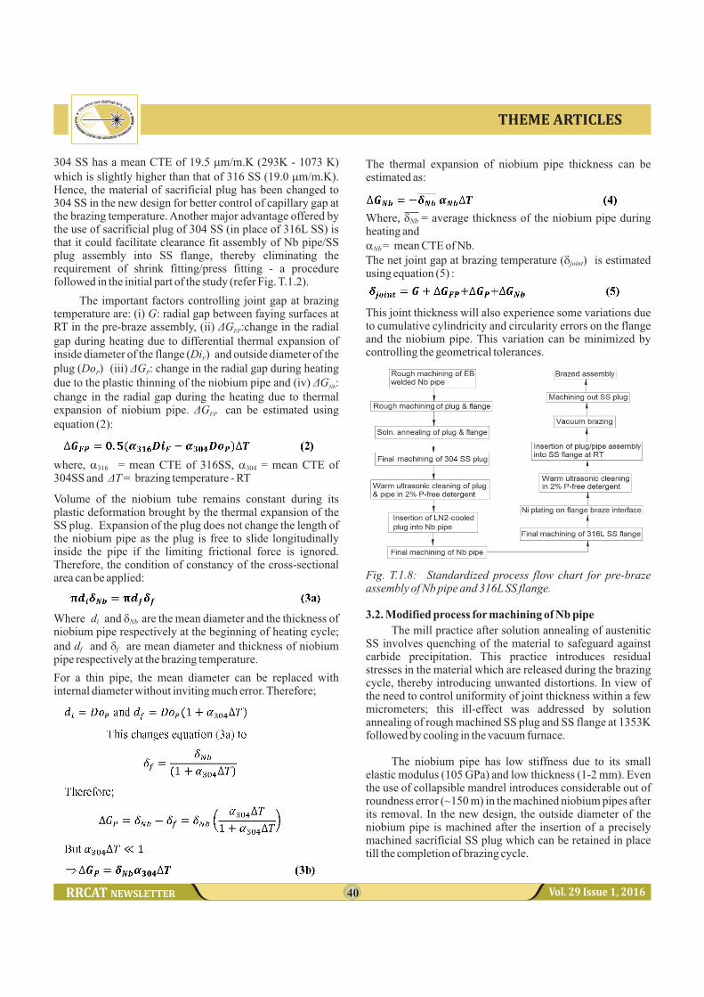
Fig. T.1.8: Standardized process flow chart for pre-braze assembly of Nb pipe and 316L SS flange.
3.2. Modified process for machining of Nb pipe
The mill practice after solution annealing of austenitic SS involves quenching of the material to safeguard against carbide precipitation. This practice introduces residual stresses in the material which are released during the brazing cycle, thereby introducing unwanted distortions. In view of the need to control uniformity of joint thickness within a few micrometers; this ill-effect was addressed by solution annealing of rough machined SS plug and SS flange at 1353K followed by cooling in the vacuum furnace.
The niobium pipe has low stiffness due to its small elastic modulus (105 GPa) and low thickness (1-2 mm). Even the use of collapsible mandrel introduces considerable out of roundness error (~150 m) in the machined niobium pipes after its removal. In the new design, the outside diameter of the niobium pipe is machined after the insertion of a precisely machined sacrificial SS plug which can be retained in place till the completion of brazing cycle.
Where, = average thickness of the niobium pipe during heating and
= mean CTE of Nb.The net joint gap at brazing temperature ( ) is estimated using equation (5) :
This joint thickness will also experience some variations due to cumulative cylindricity and circularity errors on the flange and the niobium pipe. This variation can be minimized by controlling the geometrical tolerances.
41 Vol. 29 Issue 1, 2016
THEME ARTICLES
On the basis of above discussion, the new process of machining and assembly of Nb pipe-SS plug is: (i) rough machining of internal diameter of electron beam welded niobium pipe, (ii) rough machining of the SS plug and the SS flange, (iii) solution annealing of the plug and the flange, (iv) final machining of SS plug on a precision class lathe, (v) cleaning of SS plug and niobium pipe, (vi) insertion of LN -2
cooled SS plug into niobium pipe, (v) final machining of faying surface on the outside diameter of niobium pipe to stringent geometrical tolerance and (vi) final machining of SS flange.
With this new design, circularity and cylindricity on the faying surface of niobium pipe can be effectively controlled well within 10 µm. However, a major drawback of the modified process design is that BCP of niobium, just before the pre-braze assembly, may leave acidic residue between the adjacent surfaces of the SS plug and the niobium pipe, besides reducing the diameter and impairing the cylindricity and circularity of the faying surface of niobium. In this context, an HF-free environment-friendly pre-brazing cleaning method was evaluated in place of the widely used BCP.
3.3. Elimination of BCP cleaning for Nb pipe
The experimental procedure adopted for cleaning of niobium pipe, SS plug and Ni-plated SS flange involved (i) ultrasonic cleaning in biodegradable 2% aqueous solution of phosphate free detergent (pH = 12) at 323 K for 15 minutes, (ii) rinsing in cold water and (iii) ultrasonic cleaning in 2-propenol at 333 K for 10 minutes. The results of a simplified sessile drop experiment demonstrated comparable wettability of BCP-cleaned and ultrasonically cleaned niobium surfaces.
A niobium pipe-316L SS flange assembly was also brazed while using the experimental ultrasonic cleaning method. The cleaned pre-braze assembly (along with specimens for tensile and shear tests) was wrapped in aluminum foil and stored in ambient condition for 15 hours before loading in the vacuum furnace. The resultant brazed specimens displayed tensile and shear strengths comparable to those involving cleaning with BCP. Cross-sectional examination of the resultant brazed assembly displayed defect-free joint.
On the basis of these results, the above mentioned ultrasonic cleaning treatment was adopted as pre-braze cleaning method. Important advantages offered by new cleaning method over BCP include (i) safe and environment-friendly process, (ii) no adverse effect of process residues and (iii) no deleterious effects on the diameter, the cylindricity and the circularity of the faying surface of niobium. Figure T.1.8 presents standardized flow chart for the pre-braze assembly of Nb pipe-SS flange brazing.
3.4. Self-centering of Nb pipe and SS flange
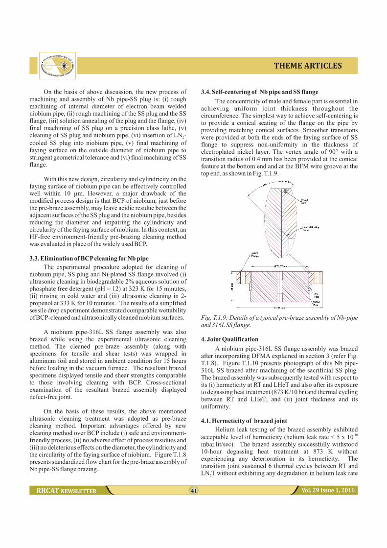
The concentricity of male and female part is essential in achieving uniform joint thickness throughout the circumference. The simplest way to achieve self-centering is to provide a conical seating of the flange on the pipe by providing matching conical surfaces. Smoother transitions were provided at both the ends of the faying surface of SS flange to suppress non-uniformity in the thickness of electroplated nickel layer. The vertex angle of 90° with a transition radius of 0.4 mm has been provided at the conical feature at the bottom end and at the BFM wire groove at the top end, as shown in Fig. T.1.9.
Fig. T.1.9: Details of a typical pre-braze assembly of Nb-pipe and 316L SS flange.
4. Joint Qualification
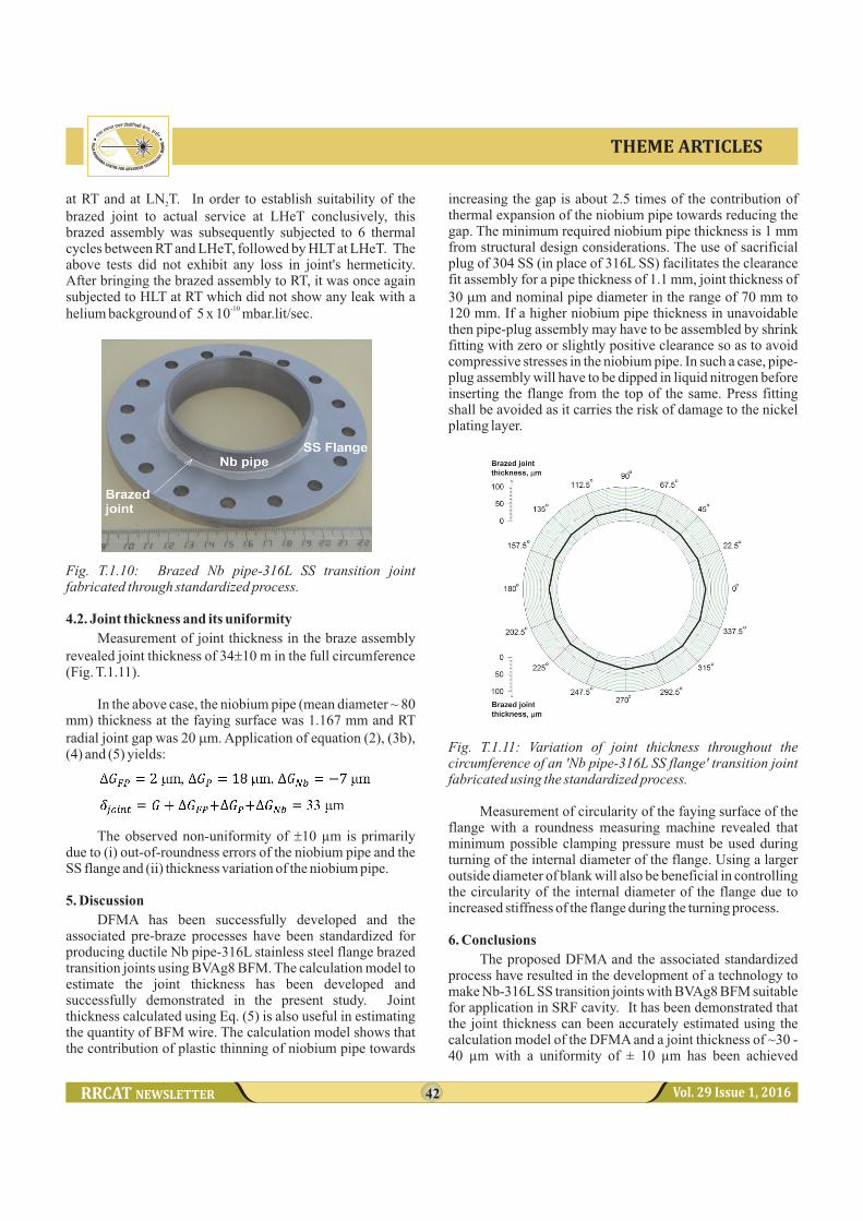
A niobium pipe-316L SS flange assembly was brazed after incorporating DFMA explained in section 3 (refer Fig. T.1.8). Figure T.1.10 presents photograph of this Nb pipe-316L SS brazed after machining of the sacrificial SS plug. The brazed assembly was subsequently tested with respect to its (i) hermeticity at RT and LHeT and also after its exposure to degassing heat treatment (873 K/10 hr) and thermal cycling between RT and LHeT; and (ii) joint thickness and its uniformity.
4.1. Hermeticity of brazed joint
Helium leak testing of the brazed assembly exhibited -10acceptable level of hermeticity (helium leak rate < 5 x 10
mbar.lit/sec). The brazed assembly successfully withstood 10-hour degassing heat treatment at 873 K without experiencing any deterioration in its hermeticity. The transition joint sustained 6 thermal cycles between RT and LN T without exhibiting any degradation in helium leak rate 2
42 Vol. 29 Issue 1, 2016
THEME ARTICLES
at RT and at LN T. In order to establish suitability of the 2
brazed joint to actual service at LHeT conclusively, this brazed assembly was subsequently subjected to 6 thermal cycles between RT and LHeT, followed by HLT at LHeT. The above tests did not exhibit any loss in joint's hermeticity. After bringing the brazed assembly to RT, it was once again subjected to HLT at RT which did not show any leak with a
-10helium background of 5 x 10 mbar.lit/sec.
Fig. T.1.10: Brazed Nb pipe-316L SS transition joint fabricated through standardized process.
4.2. Joint thickness and its uniformity
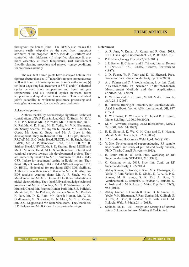
Measurement of joint thickness in the braze assembly revealed joint thickness of 34±10 m in the full circumference (Fig. T.1.11).
In the above case, the niobium pipe (mean diameter ~ 80 mm) thickness at the faying surface was 1.167 mm and RT radial joint gap was 20 mm. Application of equation (2), (3b), (4) and (5) yields:
The observed non-uniformity of ±10 µm is primarily due to (i) out-of-roundness errors of the niobium pipe and the SS flange and (ii) thickness variation of the niobium pipe.
5. Discussion
DFMA has been successfully developed and the associated pre-braze processes have been standardized for producing ductile Nb pipe-316L stainless steel flange brazed transition joints using BVAg8 BFM. The calculation model to estimate the joint thickness has been developed and successfully demonstrated in the present study. Joint thickness calculated using Eq. (5) is also useful in estimating the quantity of BFM wire. The calculation model shows that the contribution of plastic thinning of niobium pipe towards
increasing the gap is about 2.5 times of the contribution of thermal expansion of the niobium pipe towards reducing the gap. The minimum required niobium pipe thickness is 1 mm from structural design considerations. The use of sacrificial plug of 304 SS (in place of 316L SS) facilitates the clearance fit assembly for a pipe thickness of 1.1 mm, joint thickness of 30 mm and nominal pipe diameter in the range of 70 mm to 120 mm. If a higher niobium pipe thickness in unavoidable then pipe-plug assembly may have to be assembled by shrink fitting with zero or slightly positive clearance so as to avoid compressive stresses in the niobium pipe. In such a case, pipe-plug assembly will have to be dipped in liquid nitrogen before inserting the flange from the top of the same. Press fitting shall be avoided as it carries the risk of damage to the nickel plating layer.
Fig. T.1.11: Variation of joint thickness throughout the circumference of an 'Nb pipe-316L SS flange' transition joint fabricated using the standardized process.
Measurement of circularity of the faying surface of the flange with a roundness measuring machine revealed that minimum possible clamping pressure must be used during turning of the internal diameter of the flange. Using a larger outside diameter of blank will also be beneficial in controlling the circularity of the internal diameter of the flange due to increased stiffness of the flange during the turning process.
6. Conclusions
The proposed DFMA and the associated standardized process have resulted in the development of a technology to make Nb-316L SS transition joints with BVAg8 BFM suitable for application in SRF cavity. It has been demonstrated that the joint thickness can been accurately estimated using the calculation model of the DFMA and a joint thickness of ~30 - 40 µm with a uniformity of ± 10 µm has been achieved
43 Vol. 29 Issue 1, 2016
THEME ARTICLES
throughout the brazed joint. The DFMA also makes the process easily adaptable on the shop floor. Important attributes of the proposed DFMA include (i) uniform and controlled joint thickness, (ii) simplified clearance fit pre-braze assembly at room temperature, (iii) environment friendly cleaning procedure and relaxed storage conditions for pre-braze assembly.
The resultant brazed joints have displayed helium leak -10tightness better than 5 x 10 mbar.lit/s at room temperature as
well as at liquid helium temperature, besides withstanding (i) ten-hour degassing heat treatment at 873 K and (ii) 6 thermal cycles between room temperature and liquid nitrogen temperature and six thermal cycles between room temperature and liquid helium temperature. This established joint's suitability to withstand post-braze processing and testing/service induced low cycle fatigue conditions.
Acknowledgements:
Authors thankfully acknowledge significant technical contributions of Dr. P. Ram Sankar, Mr. B. K. Sindal, Mr. K. V. A. N. P. S. Kumar, Mr. D. P. Yadav, Mr. P. Chinna Rao, Dr. S. K. Rai, Mr. M. K. Singh, Mr. K. Yedle, Mr. V. K. Bhatnagar, Mr. Sanjay Sharma, Mr. Rajesh K. Prasad, Mr. Rakesh K. Gupta, Mr. Ram K. Gupta, and Mr. A. Bose in this development. They are thankful to Dr. P. D. Gupta, Director, RRCAT, Mr. S. C. Joshi, Head, PLSCD, Mr. B. Singh, Head, LMPD, Mr. A. Puntambekar, Head, SCRF-CDL,Mr. R. Sridhar, Head, UHVTS, Mr. S. D. Sharma, Head, MOSS and Mr. G Mundra, Head, ACDFS for their keen interest and continual support towards this developmental project. They are immensely thankful to Mr. P. Sarvanan of UGC-DAE-CSR, Indore for specimens' testing in liquid helium. They thankfully acknowledge UGC-DAE-CSRand Corporate R & D, BHEL, Hyderabad for providing SEM-EDS facilities. Authors express their sincere thanks to Mr. V. K. Ahire for EDS analysis. Authors thank Mr. A. P. Singh, Mr. C. Manikandan and Mr. G. S. Deshmukh for their contribution in nickel electroplating. They thankfully acknowledge technical assistance of Mr. R. Chouhan, Mr. T. P. Vishwakarma, Mr. Mukesh Chand, Mr. Pramod Kumar Patil, Mr. J. S. Pulickal, Mr. Vedpal, Mr. Om Prakash, Mr. Sanjeev Sinha, Mr. Reetesh K. Jain, Mr. D. K. Ram, Mr. Naresh Kumar, Mr. V. M. Dudhmande, Mr. S. Sarkar, Mr. N. More, Mr. T. R. Meena, Mr. D. C. Nagpure and Mr. Ram Nihal Ram. They thank Mr. J. D. Zolpara and Mr. B. Oraon for preparing drawings.
References:
1. A. R. Jana, V. Kumar, A. Kumar and R. Gaur, 2013. IEEE Trans. Appl. Superconduct., 23, 3500816 (2013).
2. P. K. Nema, Energy Procedia 7, 597 (2011).
3. J. P. Bacher, E. Chiaveri and B. Trincat, Internal Report CERN/EF/RF 87-7, CERN, Geneva, Switzerland (1987).
4. J. D. Fuerst, W. F. Toter and K. W. Shepard, Proc. Workshop on RF-Superconductivity, pp. 305 (2003).
5. A. J. Palmer and C. J. Woolstenhulm, Proc. Int. Conf. Advancements in Nuclear Instrumentat ion Measurement Methods and their Applications (ANIMMA), 1 (2009).
6. D. W. Liaw and R. K. Shiue, Metall. Mater. Trans. A, 36A, 2415 (2005).
7. R. I. Batista, Brazing of Refractory and Reactive Metals, ASM Handbook, Vol. 6: ASM International, OH, 947 (1993).
8. H. W. Chuang, D. W. Liaw, Y. C. Du and R. K. Shiue, Mater. Sci. Eng. A, 390, 350 (2005).
9. M. M. Schwartz, Brazing, ASM International, Metals Park OH, 163-164 (1987).
10. R. K. Shiue, S. K. Wu, C. H. Chan and C. S. Huang, Metall. Mater. Trans. A, 37, 2207 (2006).
11. T. Yoshida and H. Ohmura, Weld. J., 61, 363s (1982).
12. Y. Xie, Development of superconducting RF sample host cavities and study of pit induced cavity quench, Ph.D. Thesis, Cornell University (2013).
13. B. Bonin and R. W. Röth, Proc. Workshop on RF Superconductivity SRF-1991, 210 (1991).
14. O. Capatina et al, 2013. Proc. Int. Conf. on RF Superconductivity, 1192 (2013).
15. Abhay Kumar, P. Ganesh, R. Kaul, V. K. Bhatnagar, K. Yedle, P. Ram Sankar, B. K. Sindal, K. V. A. N. P. S. Kumar, M. K. Singh, S. K. Rai, A. Bose, T. Veerbhadraiah, S. Ramteke, R. Sridhar, G. Mundra, S. C. Joshi and L. M. Kukreja, J. Mater. Eng. Perf., 24(2), 952 (2015).
16. Abhay Kumar, P. Ganesh R. Kaul, B. K. Sindal, K. Yedle, V. K. Bhatnagar, P. Ram Sankar, M. K. Singh, S. K. Rai, A. Bose, R. Sridhar, S. C. Joshi and L. M. Kukreja, Weld. J., 94(8), 241s (2015).
17. Sloboda, M. H. 1961. Design and Strength of Brazed Joints. 5, London, Johnson Matthey & Co Limited.