Embed Size (px)
Citation preview

T0046 PROFESSIONAL LAN CABLE TESTER
USER GUIDE


INDEX 1. Interfaces and Controls ........................................................................1 2. Power On..............................................................................................2 3. Setup ....................................................................................................2 3.1 To set the UNIT ........................................................3 3.2 To set the LAN Length Adjustment ..........................3 3.3 To set the COAX Length Adjustment .......................3 3.4 To set the Buzzer .....................................................4 3.5 To set the Backlight ..................................................4 3.6 To restore default settings ........................................4 4. Mode Selection.....................................................................................5 5. LAN Mode – Loopback.........................................................................5 6. LAN Mode – Main to Remote Terminator ............................................7 7. TEL Mode – Cable Selection................................................................9 8. TEL Mode.............................................................................................9 9. COAX Mode – Main to Remote Terminator .......................................11 10. Tone Mode .........................................................................................12 11. Length Mode.......................................................................................12 11.1 Length Mode – LAN Cable .....................................13 11.2 Length Mode – COAX Cable ..................................14 12. Memory Function................................................................................15 12.1 Storing a screen to memory ...................................15 12.2 Recalling a screen from memory............................15 12.3 Clear screenshots from memory ............................15 13. Battery Alarm & Replacement ............................................................15
Page

Datamaster® T0046 Professional LAN Cable Tester – User Guide
Page 1
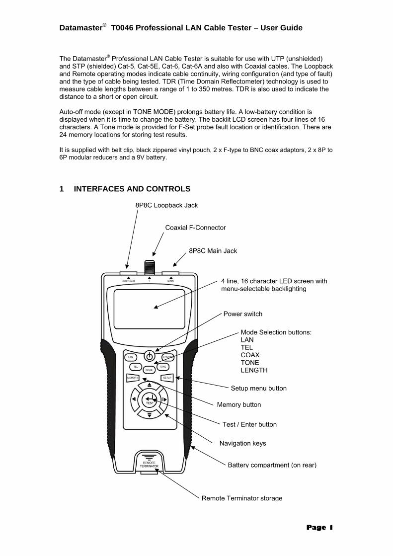
The Datamaster® Professional LAN Cable Tester is suitable for use with UTP (unshielded) and STP (shielded) Cat-5, Cat-5E, Cat-6, Cat-6A and also with Coaxial cables. The Loopback and Remote operating modes indicate cable continuity, wiring configuration (and type of fault) and the type of cable being tested. TDR (Time Domain Reflectometer) technology is used to measure cable lengths between a range of 1 to 350 metres. TDR is also used to indicate the distance to a short or open circuit. Auto-off mode (except in TONE MODE) prolongs battery life. A low-battery condition is displayed when it is time to change the battery. The backlit LCD screen has four lines of 16 characters. A Tone mode is provided for F-Set probe fault location or identification. There are 24 memory locations for storing test results. It is supplied with belt clip, black zippered vinyl pouch, 2 x F-type to BNC coax adaptors, 2 x 8P to 6P modular reducers and a 9V battery. 1 INTERFACES AND CONTROLS
8P8C Loopback Jack
Coaxial F-Connector
8P8C Main Jack
4 line, 16 character LED screen with menu-selectable backlighting
Power switch
Mode Selection buttons: LAN TEL COAX TONE LENGTH
Memory button
Setup menu button
Test / Enter button
Navigation keys
Battery compartment (on rear)
Remote Terminator storage

Datamaster® T0046 Professional LAN Cable Tester – User Guide
Page 2
2 Power On Pressing the POWER button displays a splash-screen for a few seconds. This is followed by the main menu as shown below: If no further action is taken the unit will automatically switch off after about five minutes to conserve the battery. 3 Setup Pressing the SETUP button takes you into SETUP MODE (displayed at the top of the screen).
Use the UP / DOWN NAVIGATION keys to scroll through the following menu items:
1 Unit M ◄ ► FT 2 LAN Length Adj TEST KEY 3 COAX Length Adj TEST KEY 4 Buzzer ON ◄ ► OFF 5 Backlight ON ◄ ► OFF 6 Restore Default TEST KEY
Use the LEFT / RIGHT NAVIGATION keys to select a choice or else press the TEST key if instructed to do so.
The chosen option will be flashing. Press the TEST key to choose that option. Then press the MEMORY key to lock the option into memory. Your chosen option will not be saved after power-down if the MEMORY key is not pressed.
Datamaster® T0046 Professional LAN Cable Tester – User Guide
Page 3
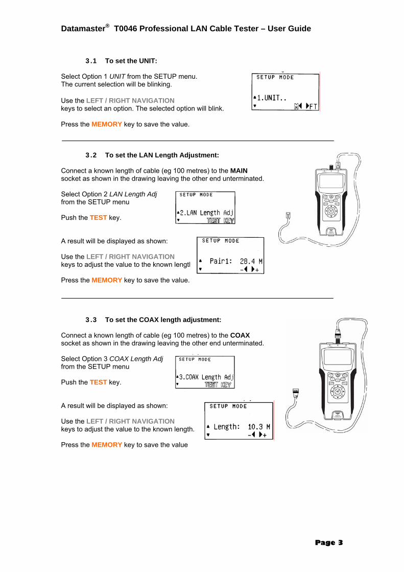
3.1 To set the UNIT: Select Option 1 UNIT from the SETUP menu. The current selection will be blinking. 3.2 To set the LAN Length Adjustment: Connect a known length of cable (eg 100 metres) to the MAIN socket as shown in the drawing leaving the other end unterminated. Select Option 2 LAN Length Adj from the SETUP menu Push the TEST key. A result will be displayed as shown: Use the LEFT / RIGHT NAVIGATION keys to adjust the value to the known length. Press the MEMORY key to save the value. 3.3 To set the COAX length adjustment: Connect a known length of cable (eg 100 metres) to the COAX socket as shown in the drawing leaving the other end unterminated. Select Option 3 COAX Length Adj from the SETUP menu Push the TEST key. A result will be displayed as shown: Use the LEFT / RIGHT NAVIGATION keys to adjust the value to the known length. Press the MEMORY key to save the value
Use the LEFT / RIGHT NAVIGATION keys to select an option. The selected option will blink. Press the MEMORY key to save the value.

Datamaster® T0046 Professional LAN Cable Tester – User Guide
Page 4
3.4 To set the Buzzer: Select Option 4 Buzzer from the SETUP menu. The current selection will be blinking. 3.5 To set the Backlight: Select Option 5 Backlight from the SETUP menu. The current selection will be blinking. Use the LEFT / RIGHT NAVIGATION keys to select an option. The selected option will blink. Press the MEMORY key to save the value 3.6 To Restore Default settings: Select Option 6 Restore Default from the SETUP menu. The words TEST KEY will be blinking. Press the TEST key. The following screen will be displayed: Press either the LEFT or RIGHT NAVIGATION key to select what you want to do.
Use the LEFT / RIGHT NAVIGATION keys to select an option. The selected option will blink. Press the MEMORY key to save the value.

Datamaster® T0046 Professional LAN Cable Tester – User Guide
Page 5
4 MODE SELECTION Use the UP /DOWN NAVIGATION keys to select one of the five operating modes shown on the main menu screen (shown opposite) OR Press one of the five blue coloured Mode Selection Buttons. 5 LAN MODE - LOOPBACK The Loopback Mode is capable of testing for the following faults:
• Open circuit • Short circuit • Crossed wires • Split wires
Enter LAN Mode from either the main menu on the screen or by pressing the blue coloured LAN button. TEST RESULTS If the cable being tested was not faulty, the display will show the type of cable (FTP or UTP) the word PASS and the word LOOP (indicating the test was performed in Loopback Mode. An FTP cable will also show a wire 0 for the shield connection in addition to the 1 – 8 data wires. The following screen-shots show the initial and the result screens for a non-faulty FTP cable.
Connect the cable between the MAIN and LOOPBACK sockets as shown in the diagram opposite. Press the TEST button. The display will indicate a PASS and the type of cable connected if there is no fault. If there is a FAIL due to a open-circuit fault, the distance to the fault will be displayed. Failures due to SHORT / SPLIT / CROSS problems will have the applicable wire pair(s) shown).

Datamaster® T0046 Professional LAN Cable Tester – User Guide
Page 6
If one (or more) pairs are open circuit, the word FAIL is displayed along with the identity of the open pair(s) (in this case, wires 1 & 2) in blinking text. The distance from the MAIN socket to the open circuit is also displayed (± 5% accuracy). Other wires will be displayed in non-blinking text to indicate that they were not faulty.
For a short circuit, the word FAIL is displayed along with the identity of the short circuited pair(s) (in this case, wires 4 & 5) in blinking text.
For crossed wires, the word FAIL is displayed along with the identity of the crossed wires (in this case, wires 1 & 2) in blinking text. Note that the crossed wires will also be displayed with an incorrect numbering sequence.
For split wires, the word FAIL is displayed along with the identity of the split wires (in this case, wires 2 & 3) in blinking text.

Datamaster® T0046 Professional LAN Cable Tester – User Guide
Page 7
6 LAN MODE – MAIN TO REMOTE TERMINATOR The Loopback mode is capable of testing for the following faults:
• Open circuit • Short circuit • Crossed wires
Enter LAN Mode from either the main menu on the screen or by pressing the blue coloured LAN button. TEST RESULTS
Connect the cable between the MAIN socket and a Remote Terminator as shown in the diagram opposite. Press the TEST button. The display will indicate a PASS and the type of cable connected if there is no fault. If there is a FAIL due to a open-circuit fault, the distance to the fault will be displayed. Failures due to SHORT or CROSS problems will have the applicable wire pair(s) shown). The ID number of the remote terminator is displayed
If one (or more) pairs are open circuit, the word FAIL is displayed along with the identity of the open pair(s) (in this case, wires 3 & 5) in blinking text. The distance from the MAIN socket to the open circuit is also displayed (± 5% accuracy). Other wires will be displayed in non-blinking text to indicate that they were not faulty. The Remote Terminator ID Number will be shown as “?”.
If the cable being tested was not faulty, the display will show the type of cable (FTP or UTP) the word PASS and the word REMOTE (indicating the test was performed in Remote Terminator Mode. An FTP cable will also show a wire 0 for the shield connection in addition to the 1 – 8 data wires. The screen-shot shows the result for a non-faulty FTP cable that was tested with Remote Terminator ID #1.

Datamaster® T0046 Professional LAN Cable Tester – User Guide
Page 8
For a short circuit, the word FAIL is displayed along with the identity of the short circuited pair(s) (in this case, wires 4 & 5) in blinking text. The Remote Terminator ID Number will be shown as “?”.
For crossed wires, the word FAIL is displayed along with the identity of the crossed wires (in this case, wires 4 & 5) in blinking text. Note that the crossed wires will also be displayed with an incorrect numbering sequence. The Remote Terminator ID Number will be shown.
For split wires, the word FAIL is displayed along with the identity of the split wires (in this case, wires 2 & 3) in blinking text.
Datamaster® T0046 Professional LAN Cable Tester – User Guide
Page 9
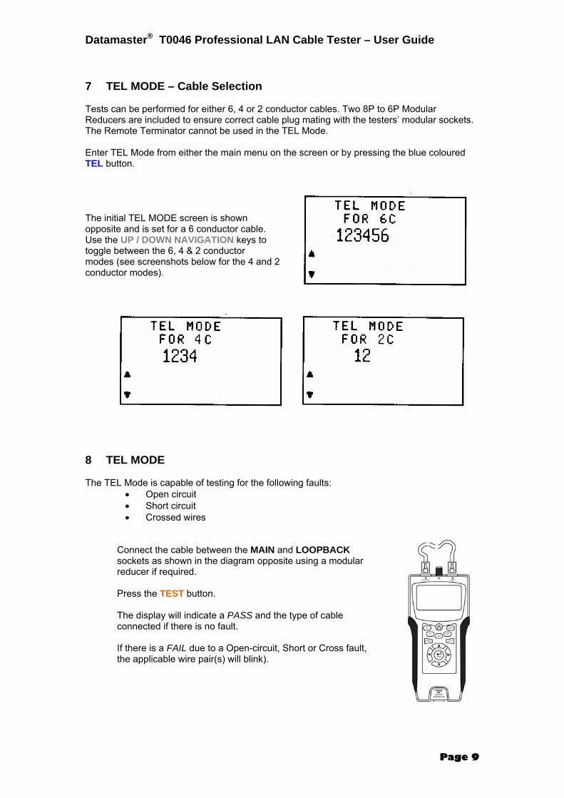
7 TEL MODE – Cable Selection Tests can be performed for either 6, 4 or 2 conductor cables. Two 8P to 6P Modular Reducers are included to ensure correct cable plug mating with the testers’ modular sockets. The Remote Terminator cannot be used in the TEL Mode. Enter TEL Mode from either the main menu on the screen or by pressing the blue coloured TEL button. The initial TEL MODE screen is shown opposite and is set for a 6 conductor cable. Use the UP / DOWN NAVIGATION keys to toggle between the 6, 4 & 2 conductor modes (see screenshots below for the 4 and 2 conductor modes). 8 TEL MODE The TEL Mode is capable of testing for the following faults:
• Open circuit • Short circuit • Crossed wires
Connect the cable between the MAIN and LOOPBACK sockets as shown in the diagram opposite using a modular reducer if required. Press the TEST button. The display will indicate a PASS and the type of cable connected if there is no fault. If there is a FAIL due to a Open-circuit, Short or Cross fault, the applicable wire pair(s) will blink).

Datamaster® T0046 Professional LAN Cable Tester – User Guide
Page 10
TEST RESULTS
If the cable being tested was not faulty, the display will show the number of conductors (in this example 6C) and the word PASS. The following screen-shots show the initial and the result screens for a non-faulty 6 conductor cable.
If one (or more) pairs are open circuit, the word FAIL is displayed along with the identity of the open pair(s) (in this case, wires 2 & 4) in blinking text. Other wires will be displayed in non-blinking text to indicate that they were not faulty.
For a short circuit, the word FAIL is displayed along with the identity of the short circuited pair(s) (in this case, wires 2 & 3) in blinking text.
For crossed wires, the word FAIL is displayed along with the identity of the crossed wires (in this case, wires 2 & 3) in blinking text. Note that the crossed wires will also be displayed with an incorrect numbering sequence.
Datamaster® T0046 Professional LAN Cable Tester – User Guide
Page 11
9 COAX MODE – MAIN TO REMOTE TERMINATOR The COAX mode is capable of testing for the following faults:
• Open circuit • Short circuit
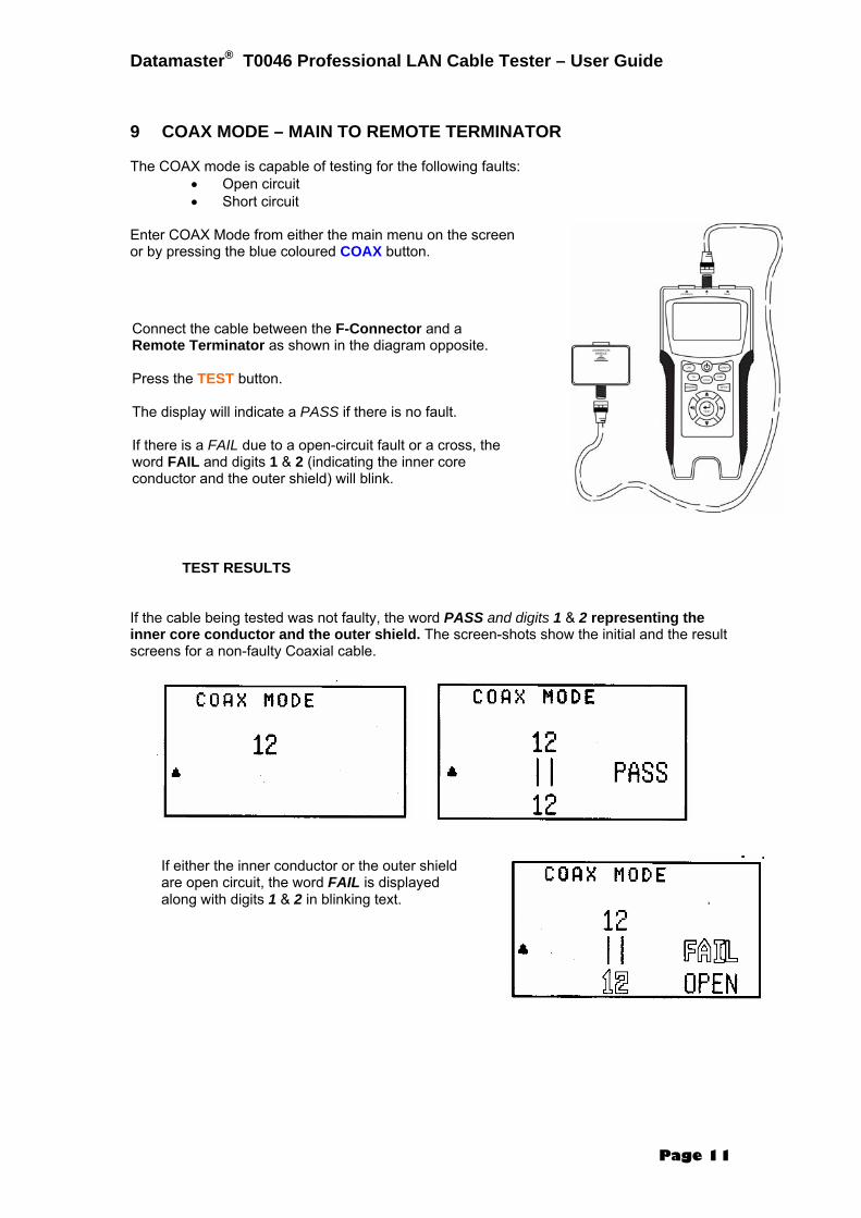
Enter COAX Mode from either the main menu on the screen or by pressing the blue coloured COAX button. TEST RESULTS If the cable being tested was not faulty, the word PASS and digits 1 & 2 representing the inner core conductor and the outer shield. The screen-shots show the initial and the result screens for a non-faulty Coaxial cable.
Connect the cable between the F-Connector and a Remote Terminator as shown in the diagram opposite. Press the TEST button. The display will indicate a PASS if there is no fault. If there is a FAIL due to a open-circuit fault or a cross, the word FAIL and digits 1 & 2 (indicating the inner core conductor and the outer shield) will blink.
If either the inner conductor or the outer shield are open circuit, the word FAIL is displayed along with digits 1 & 2 in blinking text.

Datamaster® T0046 Professional LAN Cable Tester – User Guide
Page 12
10 TONE MODE This mode transmits an audio tone to a cable plugged into the MAIN socket to allow an F-set probe to be used to find a break in the conductor. There is a choice of two tones and the conductor that the tone is transmitted along is also selectable. Enter TONE Mode from either the main menu on the screen or by pressing the blue coloured TONE button. Use the UP / DOWN NAVIGATION keys to select either Music 1 or Music 2 tone and use the LEFT / RIGHT NAVIGATION keys to select which conductor the tone is sent out on. 11 LENGTH MODE The length of a LAN or COAX cable can be measured using this mode. It is important that the other end of the cable is not terminated. Use the MAIN socket for a LAN cable and the F-Connector for a Coaxial cable as shown:
For a short circuit between the inner conductor and the outer shield, the word FAIL is displayed along with digits 1 & 2 in blinking text.
The screenshot opposite shows the Music 1 tone being transmitted over conductor #1.
OR

Datamaster® T0046 Professional LAN Cable Tester – User Guide
Page 13
Enter LENGTH Mode from either the main menu on the screen or by pressing the blue coloured LENGTH button. Use the UP / DOWN NAVIGATION keys to toggle between LAN Cable & COAX Cable tests. 11.1 LENGTH MODE – LAN CABLE Use the UP / DOWN NAVIGATION keys to toggle between LAN and COAX Length Modes.
The initial screen is shown opposite. Push either the LENGTH key or the TEST key to start the test.
If a Remote Terminator is connected to the far end of the cable, the test cannot be performed and an error message advising you to keep the remote end of the cable open is shown. Remove the Remote Terminator and re-test.
The length (± 5%) of Pair 1 (in this example 23.8 metres) will displayed. Use the LEFT / RIGHT NAVIGATION keys to see the test result for another pair. It is usual to see slightly different results for each pair in the same cable.

Datamaster® T0046 Professional LAN Cable Tester – User Guide
Page 14
11.2 LENGTH MODE – COAX CABLE Use the UP / DOWN NAVIGATION keys to toggle between LAN and COAX Length Modes.
The initial screen is shown opposite. Push either the LENGTH key or the TEST key to start the test.
If a Remote Terminator is connected to the far end of the cable, the test cannot be performed and an error message advising you to keep the remote end of the cable open is shown. Remove the Remote Terminator and re-test.
The length (± 5%) of the coaxial cable (in this example 10.3 metres) will displayed. Use the LEFT / RIGHT NAVIGATION keys to see the test result for another pair. It is usual to see slightly different results for each pair in the same cable.

Datamaster® T0046 Professional LAN Cable Tester – User Guide
Page 15
12 MEMORY FUNCTION There are 24 memory locations:
• 8 for LAN mode • 8 for TEL Mode • 4 for COAX Mode • 4 for LENGTH Mode
12.1 STORING A SCREEN TO MEMORY Whilst a test result is being displayed, it can be saved into memory by briefly pressing the MEMORY key. The memory location is momentarily displayed on the top right hand side of the screen. 12.2 RECALLING A SCREEN FROM MEMORY To recall a screen from memory, enter the appropriate mode (by pressing one of the blue coloured MODE buttons) and then press and hold the MEMORY key for at least three seconds. The results of the first memory location will be displayed. Typical memory screens are shown below: Use the UP / DOWN NAVIGATION keys to toggle between memory locations. 12.3 TO CLEAR SCREENSHOTS FROM MEMORY
If desired, enter another mode (by pressing one of the blue coloured mode selection buttons) and repeat the procedure. 13 BATTERY ALARM & REPLACEMENT
Whilst viewing any screen in memory mode, press the TEST key and the screen opposite will be displayed. Use the LEFT / RIGHT NAVIGATION keys to either cancel or retain the data stored in memory.
When the voltage of the battery drops to 6 volts, the battery icon on the left center of the screen will start to blink. Undo the Philips-head screw on the battery compartment lid on the rear of the tester and replace the battery.