Embed Size (px)
Citation preview
T-VEC: A Tool for Developing Critical Systems
Mark R. Blackburn Robert D. Busser Software Productivity Consortium T-VEC Technologies [email protected] [email protected]
Abstract This paper describes the specification-based testing
and analysis tools, and associated processes, that were used to develop and certify safety-critical avionics systems in an industrial organization. These tools comprise an integrated development environment supporting specification acquisition and analysis, requirement-based automatic test vector generation, test coverage analysis, test driver generation, and test results analysis. The paper describes the specification model, method, development environment, and tool qualification approach. The capabilities of the automatic test generator are compared with foundational concepts and related testing strategies and mechanisms.
1. Introduction
This paper describes the T-VEC (Test VECtor) system that was used to develop and certify two avionics systems. These certifications were conducted by the Federal Aviation Administration (FAA) based on DO-178A - Software Considerations in Airborne Systems and Equipment Certification [24] (now DO-178B). These certification guidelines emphasize a software engineering approach, where requirement-based testing and analysis are key to supporting the assurance arguments required for certification.
T-VEC is an integrated development environment and associated specification and verification method [3; 4]. One of the key tools of the T-VEC system is an automatic test vector generator; it determines test inputs, expected outputs, and a mapping of each test to the associated requirement, directly from formal specifications. It has been documented that testing can account for 40% to 70% of the development effort [5; 14]. Testing a critical system can require tens or hundreds of thousands of test cases. A test vector generator that determines expected output values can reduce the testing effort as compared to a test case
generator, where the expected output values must be determined manually.
1.1 T-VEC overview
Figure 1 shows the T-VEC Environment. It supports a process that produces a hierarchy of requirement and design specifications. Graphical editors are employed in the acquisition of different aspects of the specification. The T-VEC compiler checks syntactic and semantic information during the compilation of the requirement specification. The test vector generator derives test vectors from the system knowledge. Its automatic coverage analyzer ensures that every unique requirement specification is exercised by at least one test vector. T-VEC also automatically generates test drivers and documentation, relieving engineers from such tedious tasks. Finally, T-VEC provides project and configuration management tools specifically developed to support the method.
1.2 T-VEC in operation
T-VEC is operational today. It has been used to develop flight-critical, real-time, embedded systems since 1989. As a result of this experience, T-VEC evolved and was tailored to aid engineers in applying formal specifications by representing them using graphics with textual annotations. T-VEC was applied to a portion (approximately 50 subsystems) of a Traffic and Collision Avoidance System (TCAS), which was FAA-certified in March of 1990. T-VEC was applied to the entire MD90 (McDonnell Douglas) Electrical Power System Variable Speed Constant Frequency (VSCF) system that was FAA-certified in January of 1995. T-VEC was also used in the development of component libraries for a family of avionics display systems. T-VEC was also qualified in support of the certification requirements (see Section 5).
Copyright (c) 1996 Institute of Electrical and Electronics Engineers. Reprinted, with permission, from the Proceedings of COMPASS 96.
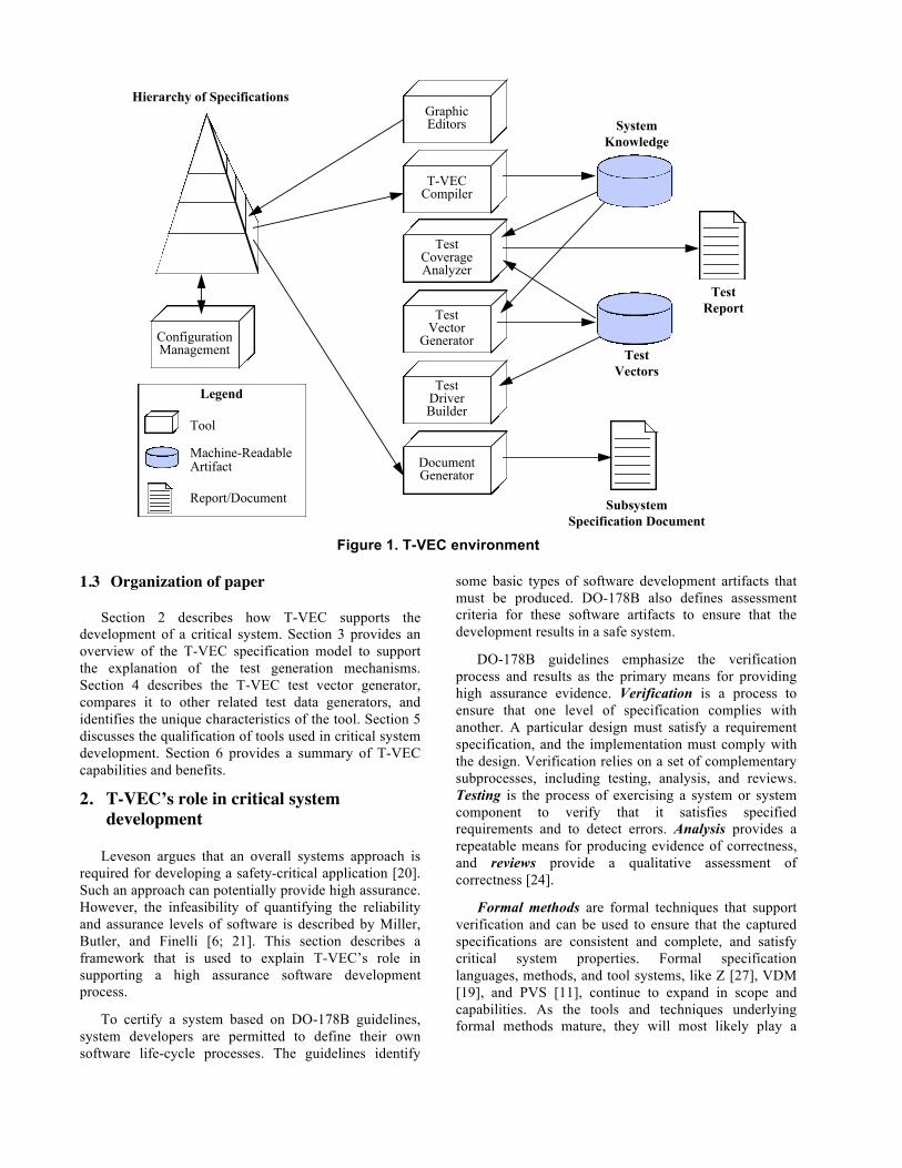
Figure 1. T-VEC environment
1.3 Organization of paper
Section 2 describes how T-VEC supports the development of a critical system. Section 3 provides an overview of the T-VEC specification model to support the explanation of the test generation mechanisms. Section 4 describes the T-VEC test vector generator, compares it to other related test data generators, and identifies the unique characteristics of the tool. Section 5 discusses the qualification of tools used in critical system development. Section 6 provides a summary of T-VEC capabilities and benefits.
2. T-VEC’s role in critical system development
Leveson argues that an overall systems approach is required for developing a safety-critical application [20]. Such an approach can potentially provide high assurance. However, the infeasibility of quantifying the reliability and assurance levels of software is described by Miller, Butler, and Finelli [6; 21]. This section describes a framework that is used to explain T-VEC’s role in supporting a high assurance software development process.
To certify a system based on DO-178B guidelines, system developers are permitted to define their own software life-cycle processes. The guidelines identify
some basic types of software development artifacts that must be produced. DO-178B also defines assessment criteria for these software artifacts to ensure that the development results in a safe system.
DO-178B guidelines emphasize the verification process and results as the primary means for providing high assurance evidence. Verification is a process to ensure that one level of specification complies with another. A particular design must satisfy a requirement specification, and the implementation must comply with the design. Verification relies on a set of complementary subprocesses, including testing, analysis, and reviews. Testing is the process of exercising a system or system component to verify that it satisfies specified requirements and to detect errors. Analysis provides a repeatable means for producing evidence of correctness, and reviews provide a qualitative assessment of correctness [24].
Formal methods are formal techniques that support verification and can be used to ensure that the captured specifications are consistent and complete, and satisfy critical system properties. Formal specification languages, methods, and tool systems, like Z [27], VDM [19], and PVS [11], continue to expand in scope and capabilities. As the tools and techniques underlying formal methods mature, they will most likely play a
T-VECCompiler
DocumentGenerator
TestDriverBuilder
TestCoverageAnalyzer
ConfigurationManagement
TestVectorGenerator
SystemKnowledge
TestVectors
TestReport
SubsystemSpecification Document
Hierarchy of Specifications
Legend
Tool
Machine-ReadableArtifact
Report/Document
GraphicEditors
larger role in the development of critical systems because they help identify specification errors.
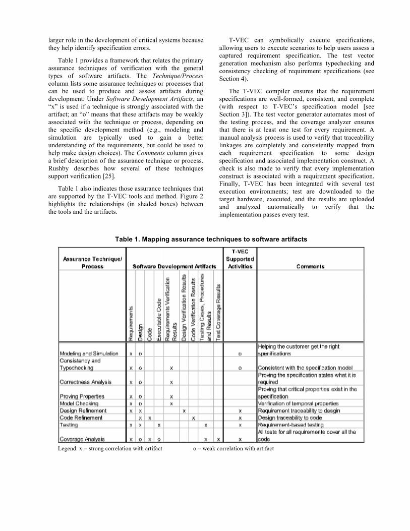
Table 1 provides a framework that relates the primary assurance techniques of verification with the general types of software artifacts. The Technique/Process column lists some assurance techniques or processes that can be used to produce and assess artifacts during development. Under Software Development Artifacts, an “x” is used if a technique is strongly associated with the artifact; an “o” means that these artifacts may be weakly associated with the technique or process, depending on the specific development method (e.g., modeling and simulation are typically used to gain a better understanding of the requirements, but could be used to help make design choices). The Comments column gives a brief description of the assurance technique or process. Rushby describes how several of these techniques support verification [25].
Table 1 also indicates those assurance techniques that are supported by the T-VEC tools and method. Figure 2 highlights the relationships (in shaded boxes) between the tools and the artifacts.
T-VEC can symbolically execute specifications, allowing users to execute scenarios to help users assess a captured requirement specification. The test vector generation mechanism also performs typechecking and consistency checking of requirement specifications (see Section 4).
The T-VEC compiler ensures that the requirement specifications are well-formed, consistent, and complete (with respect to T-VEC’s specification model [see Section 3]). The test vector generator automates most of the testing process, and the coverage analyzer ensures that there is at least one test for every requirement. A manual analysis process is used to verify that traceability linkages are completely and consistently mapped from each requirement specification to some design specification and associated implementation construct. A check is also made to verify that every implementation construct is associated with a requirement specification. Finally, T-VEC has been integrated with several test execution environments; test are downloaded to the target hardware, executed, and the results are uploaded and analyzed automatically to verify that the implementation passes every test.
Table 1. Mapping assurance techniques to software artifacts
Legend: x = strong correlation with artifact o = weak correlation with artifact
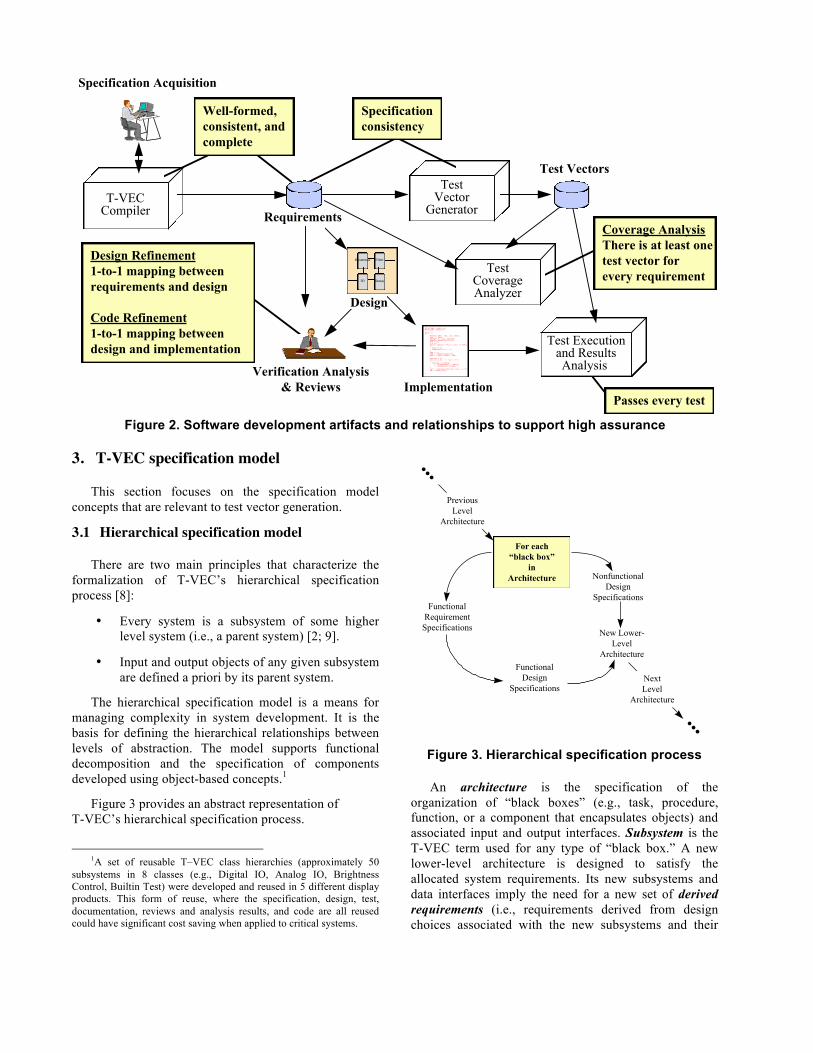
Figure 2. Software development artifacts and relationships to support high assurance
3. T-VEC specification model
This section focuses on the specification model concepts that are relevant to test vector generation.
3.1 Hierarchical specification model
There are two main principles that characterize the formalization of T-VEC’s hierarchical specification process [8]:
• Every system is a subsystem of some higher level system (i.e., a parent system) [2; 9].
• Input and output objects of any given subsystem are defined a priori by its parent system.
The hierarchical specification model is a means for managing complexity in system development. It is the basis for defining the hierarchical relationships between levels of abstraction. The model supports functional decomposition and the specification of components developed using object-based concepts.1
Figure 3 provides an abstract representation of T-VEC’s hierarchical specification process.
1A set of reusable T–VEC class hierarchies (approximately 50
subsystems in 8 classes (e.g., Digital IO, Analog IO, Brightness Control, Builtin Test) were developed and reused in 5 different display products. This form of reuse, where the specification, design, test, documentation, reviews and analysis results, and code are all reused could have significant cost saving when applied to critical systems.
Figure 3. Hierarchical specification process
An architecture is the specification of the organization of “black boxes” (e.g., task, procedure, function, or a component that encapsulates objects) and associated input and output interfaces. Subsystem is the T-VEC term used for any type of “black box.” A new lower-level architecture is designed to satisfy the allocated system requirements. Its new subsystems and data interfaces imply the need for a new set of derived requirements (i.e., requirements derived from design choices associated with the new subsystems and their
Requirements
Design
Implementation
#include <stdio.h>#include <math.h>
main (){ double med, var, sd, mean; int i, len; double n, sum, varsum; double numbers[1000]; sum = 0; i = 0; while (scanf ("%lf", &n) != EOF) { sum += n; numbers[i++] = n; } len = i; med = numbers[len/2]; mean = sum/(float) len;
varsum = 0; for (i = 0; i < len; i++) { varsum = varsum + ((numbers[i]- mean) * (numbers[i]-mean)); } var = varsum/((float) len - 1.0); sd = sqrt(var);
}
Specification Acquisition
Test Vectors
Test Executionand ResultsAnalysis Verification Analysis
& Reviews
T-VECCompiler
TestCoverageAnalyzer
TestVector
Generator
Design Refinement1-to-1 mapping betweenrequirements and design
Code Refinement1-to-1 mapping betweendesign and implementation
Coverage AnalysisThere is at least onetest vector forevery requirement
Well-formed,consistent, andcomplete
Passes every test
Specificationconsistency
StatusIO
FilterHysteresis
...
For each“black box”
inArchitecture
PreviousLevel
Architecture
FunctionalRequirementSpecifications
FunctionalDesign
Specifications
NonfunctionalDesign
Specifications
New Lower-Level
Architecture
NextLevel
Architecture
...
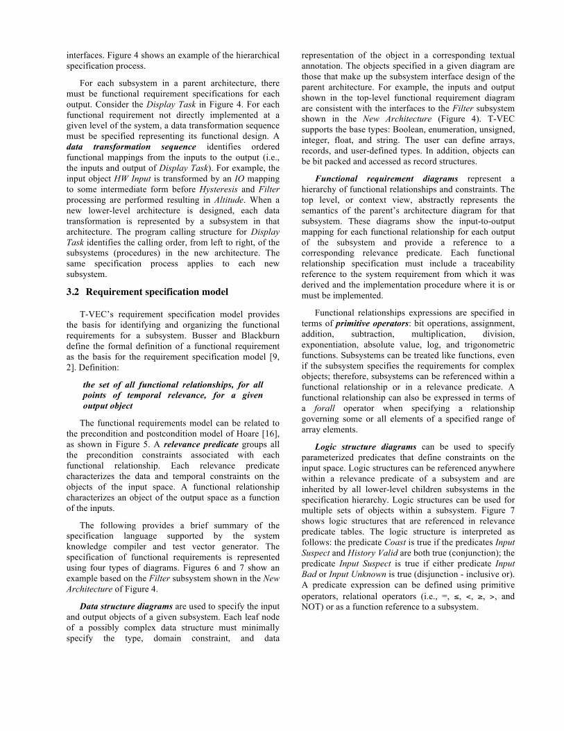
interfaces. Figure 4 shows an example of the hierarchical specification process.
For each subsystem in a parent architecture, there must be functional requirement specifications for each output. Consider the Display Task in Figure 4. For each functional requirement not directly implemented at a given level of the system, a data transformation sequence must be specified representing its functional design. A data transformation sequence identifies ordered functional mappings from the inputs to the output (i.e., the inputs and output of Display Task). For example, the input object HW Input is transformed by an IO mapping to some intermediate form before Hysteresis and Filter processing are performed resulting in Altitude. When a new lower-level architecture is designed, each data transformation is represented by a subsystem in that architecture. The program calling structure for Display Task identifies the calling order, from left to right, of the subsystems (procedures) in the new architecture. The same specification process applies to each new subsystem.
3.2 Requirement specification model
T-VEC’s requirement specification model provides the basis for identifying and organizing the functional requirements for a subsystem. Busser and Blackburn define the formal definition of a functional requirement as the basis for the requirement specification model [9, 2]. Definition:
the set of all functional relationships, for all points of temporal relevance, for a given output object
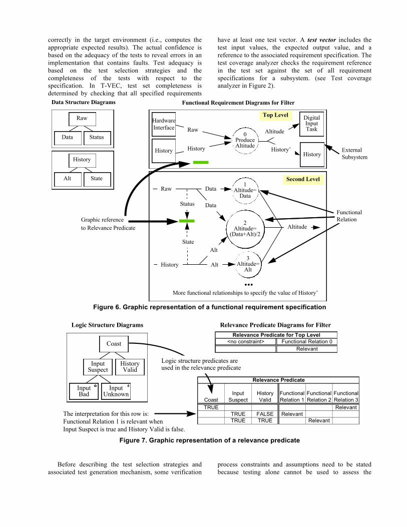
The functional requirements model can be related to the precondition and postcondition model of Hoare [16], as shown in Figure 5. A relevance predicate groups all the precondition constraints associated with each functional relationship. Each relevance predicate characterizes the data and temporal constraints on the objects of the input space. A functional relationship characterizes an object of the output space as a function of the inputs.
The following provides a brief summary of the specification language supported by the system knowledge compiler and test vector generator. The specification of functional requirements is represented using four types of diagrams. Figures 6 and 7 show an example based on the Filter subsystem shown in the New Architecture of Figure 4.
Data structure diagrams are used to specify the input and output objects of a given subsystem. Each leaf node of a possibly complex data structure must minimally specify the type, domain constraint, and data
representation of the object in a corresponding textual annotation. The objects specified in a given diagram are those that make up the subsystem interface design of the parent architecture. For example, the inputs and output shown in the top-level functional requirement diagram are consistent with the interfaces to the Filter subsystem shown in the New Architecture (Figure 4). T-VEC supports the base types: Boolean, enumeration, unsigned, integer, float, and string. The user can define arrays, records, and user-defined types. In addition, objects can be bit packed and accessed as record structures.
Functional requirement diagrams represent a hierarchy of functional relationships and constraints. The top level, or context view, abstractly represents the semantics of the parent’s architecture diagram for that subsystem. These diagrams show the input-to-output mapping for each functional relationship for each output of the subsystem and provide a reference to a corresponding relevance predicate. Each functional relationship specification must include a traceability reference to the system requirement from which it was derived and the implementation procedure where it is or must be implemented.
Functional relationships expressions are specified in terms of primitive operators: bit operations, assignment, addition, subtraction, multiplication, division, exponentiation, absolute value, log, and trigonometric functions. Subsystems can be treated like functions, even if the subsystem specifies the requirements for complex objects; therefore, subsystems can be referenced within a functional relationship or in a relevance predicate. A functional relationship can also be expressed in terms of a forall operator when specifying a relationship governing some or all elements of a specified range of array elements.
Logic structure diagrams can be used to specify parameterized predicates that define constraints on the input space. Logic structures can be referenced anywhere within a relevance predicate of a subsystem and are inherited by all lower-level children subsystems in the specification hierarchy. Logic structures can be used for multiple sets of objects within a subsystem. Figure 7 shows logic structures that are referenced in relevance predicate tables. The logic structure is interpreted as follows: the predicate Coast is true if the predicates Input Suspect and History Valid are both true (conjunction); the predicate Input Suspect is true if either predicate Input Bad or Input Unknown is true (disjunction - inclusive or). A predicate expression can be defined using primitive operators, relational operators (i.e., =, ≤, <, ≥, >, and NOT) or as a function reference to a subsystem.
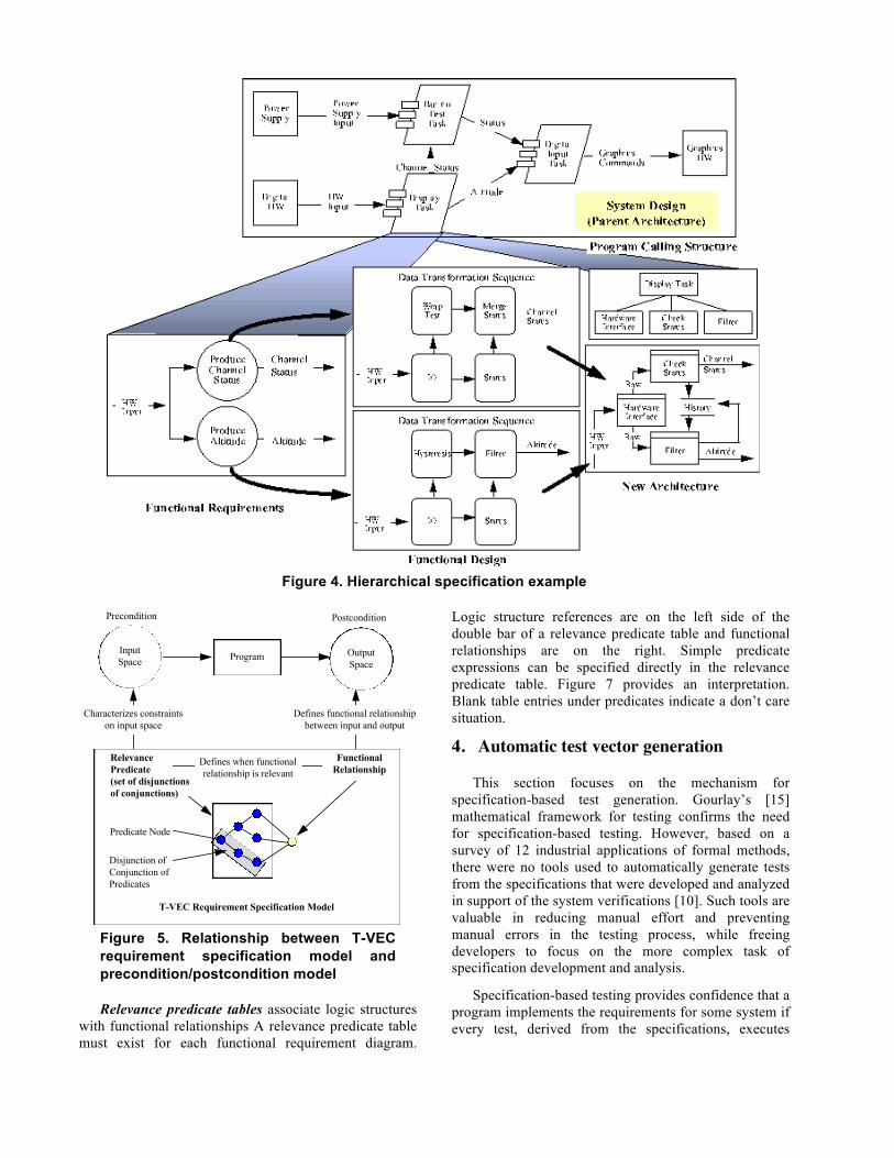
Figure 4. Hierarchical specification example
Figure 5. Relationship between T-VEC requirement specification model and precondition/postcondition model
Relevance predicate tables associate logic structures with functional relationships A relevance predicate table must exist for each functional requirement diagram.
Logic structure references are on the left side of the double bar of a relevance predicate table and functional relationships are on the right. Simple predicate expressions can be specified directly in the relevance predicate table. Figure 7 provides an interpretation. Blank table entries under predicates indicate a don’t care situation.
4. Automatic test vector generation
This section focuses on the mechanism for specification-based test generation. Gourlay’s [15] mathematical framework for testing confirms the need for specification-based testing. However, based on a survey of 12 industrial applications of formal methods, there were no tools used to automatically generate tests from the specifications that were developed and analyzed in support of the system verifications [10]. Such tools are valuable in reducing manual effort and preventing manual errors in the testing process, while freeing developers to focus on the more complex task of specification development and analysis.
Specification-based testing provides confidence that a program implements the requirements for some system if every test, derived from the specifications, executes
OutputSpace
Characterizes constraintson input space
Defines functional relationshipbetween input and output
Precondition Postcondition
InputSpace Program
RelevancePredicate(set of disjunctionsof conjunctions)
FunctionalRelationship
Disjunction ofConjunction of Predicates
Defines when functionalrelationship is relevant
Predicate Node
T-VEC Requirement Specification Model
correctly in the target environment (i.e., computes the appropriate expected results). The actual confidence is based on the adequacy of the tests to reveal errors in an implementation that contains faults. Test adequacy is based on the test selection strategies and the completeness of the tests with respect to the specification. In T-VEC, test set completeness is determined by checking that all specified requirements
have at least one test vector. A test vector includes the test input values, the expected output value, and a reference to the associated requirement specification. The test coverage analyzer checks the requirement reference in the test set against the set of all requirement specifications for a subsystem. (see Test coverage analyzer in Figure 2).
Figure 6. Graphic representation of a functional requirement specification
Figure 7. Graphic representation of a relevance predicate
Before describing the test selection strategies and associated test generation mechanism, some verification
process constraints and assumptions need to be stated because testing alone cannot be used to assess the
Raw
Data Status
History
Alt State
0ProduceAltitudeHistory
Raw Altitude
1Altitude=
Data
History
Raw
Altitude
Data
2Altitude=
(Data+Alt)/2
3Altitude=
Alt
DataStatus
State
Alt
Alt
Graphic referenceto Relevance Predicate
Data Structure Diagrams Functional Requirement Diagrams for Filter
Top Level
Second Level
ExternalSubsystem
FunctionalRelation
DigitalInputTask
HardwareInterface
History HistoryHistory’
...More functional relationships to specify the value of History’
Logic Structure DiagramsRelevance Predicate for Top Level
<no constraint> Functional Relation 0Relevant
Relevance Predicate Diagrams for Filter
Coast
InputSuspect
HistoryValid
InputBad
InputUnknown
The interpretation for this row is:Functional Relation 1 is relevant whenInput Suspect is true and History Valid is false.
Logic structure predicates are used in the relevance predicate
Relevance Predicate
CoastInput
SuspectHistory Valid
Functional Relation 1
Functional Relation 2
Functional Relation 3
TRUE RelevantTRUE FALSE RelevantTRUE TRUE Relevant
completeness or consistency between a specification and an implementation.
4.1 Verification constraints and assumptions
The specification is assumed to be correct, although as discussed later in this section, the test vector generator can detect inconsistencies in the specification. To provide assurance that the implementation is complete and consistent with respect to the specification, the following manual review processes were used to support the FAA certifications in which T-VEC was used:
• Every functional relationship (FR) in the specification must be mapped to an output assignment in the implementation, and there must be a 1-to-1 mapping between the relevance predicate constraints of the FR and the conditions on the program path to the assignment.
• For every function/procedure call in a program, there must be a consistent interface mapping to a “lower-level” subsystem specification (this allows the same mechanisms to be used for all levels of the software system).
It is assumed that an implementor follows these rules when coding from a formal specification. It is also assumed that there is a strong correlation between the relevance predicates and path controls guarding the output assignments of a program even if a human fails to detect an inconsistency between the specification and implementation.
4.2 Test selection strategy
T-VEC is as an oracle/error-based testing mechanism based on Richardson’s et. al [23] classification of specification-based testing approaches; such approaches extend implementation-based testing techniques to formal specifications. This subsection relates implementation-based testing concepts and strategies to the T-VEC test selection mechanisms.
Using Zeil’s [31] modified version of Howden’s [17] definitions: a computation error occurs when the correct path through the program is taken, but the output is incorrect due to faults in the computation along the path. A domain error occurs when an incorrect output is generated due to executing the wrong path through a program. Howden further categorized domain errors as path selection errors or missing path errors [17]. Specification-based testing can detect missing path errors; however, in general, we assume that missing and extraneous paths in the code will be detected during a manual review process. T-VEC mechanisms can detect both domain and computation errors.
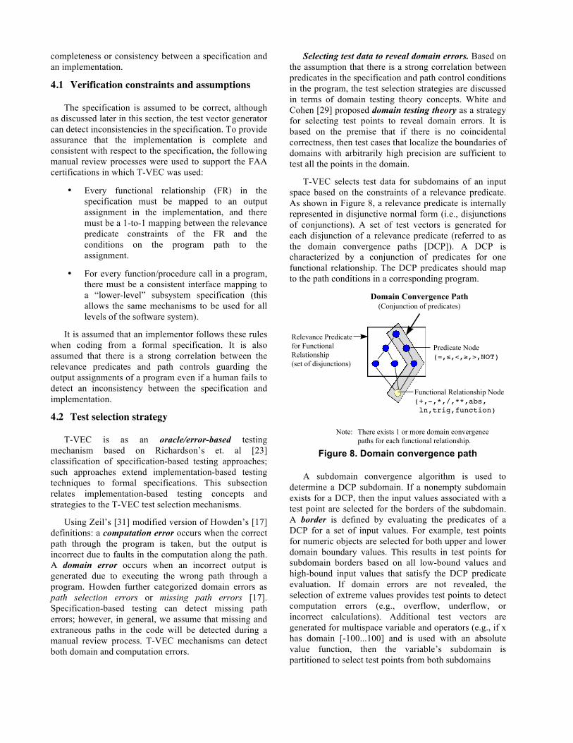
Selecting test data to reveal domain errors. Based on the assumption that there is a strong correlation between predicates in the specification and path control conditions in the program, the test selection strategies are discussed in terms of domain testing theory concepts. White and Cohen [29] proposed domain testing theory as a strategy for selecting test points to reveal domain errors. It is based on the premise that if there is no coincidental correctness, then test cases that localize the boundaries of domains with arbitrarily high precision are sufficient to test all the points in the domain.
T-VEC selects test data for subdomains of an input space based on the constraints of a relevance predicate. As shown in Figure 8, a relevance predicate is internally represented in disjunctive normal form (i.e., disjunctions of conjunctions). A set of test vectors is generated for each disjunction of a relevance predicate (referred to as the domain convergence paths [DCP]). A DCP is characterized by a conjunction of predicates for one functional relationship. The DCP predicates should map to the path conditions in a corresponding program.
Figure 8. Domain convergence path
A subdomain convergence algorithm is used to determine a DCP subdomain. If a nonempty subdomain exists for a DCP, then the input values associated with a test point are selected for the borders of the subdomain. A border is defined by evaluating the predicates of a DCP for a set of input values. For example, test points for numeric objects are selected for both upper and lower domain boundary values. This results in test points for subdomain borders based on all low-bound values and high-bound input values that satisfy the DCP predicate evaluation. If domain errors are not revealed, the selection of extreme values provides test points to detect computation errors (e.g., overflow, underflow, or incorrect calculations). Additional test vectors are generated for multispace variable and operators (e.g., if x has domain [-100...100] and is used with an absolute value function, then the variable’s subdomain is partitioned to select test points from both subdomains
Predicate Node(=,≤,<,≥,>,NOT)
Functional Relationship Node(+,-,*,/,**,abs, ln,trig,function)
Relevance Predicatefor FunctionalRelationship(set of disjunctions)
Note: There exists 1 or more domain convergence paths for each functional relationship.
Domain Convergence Path(Conjunction of predicates)
[-100...0] and [0...100]). Intuitively, this specification-based domain testing mechanism provides confidence that every path of the implementation is correct with respect to every DCP and functional relationship of a subsystem.
Problem domain test selection heuristics. A heuristic mechanism was added to the test generator to control the order of the selection of borders of subdomain boundaries based on three categories of predicates. By distinguishing the predicate types, the test points are selected on boundaries that are more strongly correlated to the problem domain boundaries. Predicates in the DCP are categorized by clause type. The clause types include:
• ground term: an input variable used in a relation with a constant
• ground clause: a variable and/or function used in a relation with a constant
• clause: a relation between any combination of two or more input variables and/or functions
Ground terms relate an input variable to a constant; this constant is likely to have significant meaning in the problem domain. For example, in TCAS, if an aircraft is above 10,000 feet (ground term), and if an aircraft is within 2,500 feet of altitude of your own aircraft altitude (ground clause), it is a candidate for tracking by TCAS. Therefore, ground terms are used to initialize the subdomain for a DCP before a ground clause or clause is used to constrain the subdomain.2
Selecting test data to reveal computation errors. Some inputs to the functional relationship are not constrained by the DCP predicates. For each test point derived from DCP predicates, there are additional test points derived for unconstrained inputs not referenced in the DCP based on all domain boundary value combinations (i.e., low bound and high bound for numeric objects, sets for enumerated variable, etc.). By selecting the extreme value combinations, there is a possibility to detect computation errors in the output calculation. This test selection strategy is used to detect computation errors or show that unconstrained inputs do not affect the output for a program path.
Computing the expected output. The functional relationship is applied to each input value set to determine the expected output value. The value is
2The TCAS Collision Avoidance Logic, developed by two independent organizations, is a pseudo-code specification that TCAS system developers must implement in their system. These specifications have evolved over the last 20 years. A change was made between version 5 and version 6 that specified unreachable code. To test the code, the specifications were reverse-engineered into T-VEC specifications. T-VEC’s use of domain boundaries helped identify a complex combination of constraints that were inconsistent in version 6. Values inside the boundaries would not have detected this inconsistency.
checked against the subrange specification of the output variable, if the value is within the specified range, a test vector is produced that includes the inputs, input types and representation information, the expected output with its type information, and the requirement DCP.
Specification inconsistencies are identified when the test coverage analyzer cannot find a complete mapping between the generated test vectors and the set of all DCP combinations in the source specification for each subsystem. Specification inconsistencies result when the test generator does not produce test vectors; this occurs when:
• The convergence process cannot determine an input subdomain for a DCP because there is an inconsistent set of predicates in the DCP.
• The expected output value, computed using the functional relationship with the input test values, is not correct with respect to its subrange specification.
There is an interactive specification analysis tool (“debugger”) that can be used to determine the source of a specification inconsistency.
4.3 Relationship to other strategies
Domain testing strategies have focused on programs rather than specifications, but the foundational concepts can be related to specification-based test selection. The initial domain testing strategy proposals [12; 29], had some limitations and flawed arguments as described by Zeil [31]. Zeil et al. [30] describes an extension to support nonlinear calculations for linearly independent predicate expressions. Zeng and Weyuker [18] describe a simplified strategy that reduces the number of test points and addresses the limitation of programs with variable defined over continuous domains.
In 1990, T-VEC mechanisms [4] supported the extension addressed by Zeng and Weyuker [18]:
• For a discrete input space with open borders defined by > and < relational operators, the selection of test points is based on the floating point representation of the input objects with respect to their computed accuracy of the calculations used in the predicate expressions.
and extended Zeil’s et al. [30] contributions to address the needs of real-world applications, by supporting:
• Borders associated with predicate expressions that are linearly dependent nonlinear inequalities. As is discussed in Afifi et al. [1], real-world problems (e.g., TCAS, global navigation) contain nonlinear constraints and functions.
As an oracle-based mechanism, T-VEC deviates from the implementation-based strategies in one way. Implementation-based strategies select test points ON the borders (within the subdomain) and OFF the borders in an adjacent subdomain. T-VEC selects only ON border test points, because it cannot determine the expected output for an OFF border test point in an adjacent domain based on the current DCP and functional relationship. The expected output for an OFF border test point in an adjacent subdomain should be covered by another relevance predicate of the specification.
4.4 Relationship to other test generators
T-VEC is a mechanized instance within a general framework for specification-based testing as described by Stocks and Carrington [26]. It uses specification categories (see Section 4.2) to select test data based on a test point selection strategy. Convergence operations, based on the specification precondition, are used to reduce the input space, and test point heuristics are used to select test points.
Some other test generation systems use functional specifications, where a precondition defines constraints on the function’s input domain. The characteristics that distinguish the systems include:
• The ability to generate test vectors versus test cases
• The ability to select test data for specifications characterized as nonlinear inequalities with dependent variables
• The mechanization of the test generator
• The test point selection heuristics and mechanisms
Some specification-based test generators produce test cases, like the system “T” developed by Poston [22]. Tsai et al. describes a test generator for a relational algebra specification [28], where the specification precondition is limited to a set of linear inequalities.
Prolog-like engines were used by Busser and Blackburn [4], Denney [13], and Bernot et al. [7] to automate test generation. In all cases, additional control strategies were required to overcome some of the limitations of Prolog (i.e., the Horn clause representation, typeless language). The executable nature of the specification language supports the selection of the test input values and the computation of the expected output value.
4.5 Unique characteristics of T-VEC test vector generator
The distinguishing characteristics of T-VEC include:
• T-VEC generates test vectors for specifications characterized by nonlinear inequalities, where both sides of the inequality can be expressions with dependent variables, rather than being limited to linear inequalities with constants.
• T-VEC generates test vectors involving complex structures and arrays for both input and output spaces.
• T-VEC generates test vectors using selection heuristics (e.g., limit the number of combinations of unconstrained input variable to all low-bound, and all high-bound values).
• T-VEC generates test vectors for a hierarchy of specifications, supporting integration testing of a high-level subsystem, without regenerating all the test vectors for each referenced lower-level subsystem. This mechanism precludes the combinatorial explosion associated with tests generated from the combination of constraints in a hierarchy of subsystems, while ensuring complete coverage when following a bottom-up testing strategy.
The concept of hierarchical specification is fundamental to the scalability of both the specification method and the associated verification process. T-VEC promotes a hierarchy of specifications to manage complexity, changeability, and reuse, as well as scalability.
4.6 Automated test process
After completing the specification and coding processes, developers submit the subsystem for testing. T-VEC executes the following procedure automatically relieving engineers from many manual tasks and
reducing the possibility of manual error (refer to Figure 2):
• T-VEC checks and compiles, as needed, the system knowledge to ensure that it is up-to-date with the graphically entered specification.
• If it is error free, T-VEC generates test vectors from the system knowledge.
• T-VEC checks to ensure that there is at least one test vector for every requirement specification DCP.
• If there is full test coverage, T-VEC generates and submits a test driver to the target hardware.
• The actual outputs (associated with the test sets) are automatically uploaded from the target test environment and compared to the expected outputs (from the test vectors).
4.7 Test vector generation example
This section illustrates the mechanisms of the test vector generator using an example specification fragment. Table 2 shows an example of a relevance predicate. Clause types are identified in the second column.
Table 2. Relevance predicate example
Table 3 provides a way to view the subranges on the inputs during the domain convergence process. The steps of the convergence process are numbered to support the following discussion of the process. After every operation, there is a propagation step that is used to ensure that all constraints are still satisfied. If any constraint cannot be satisfied, then the specification is inconsistent.
• Step 0 shows the initial domain for each variable.
• Step 1 limits the domain based on all ground terms to ensure that the selected test points are near a subdomain boundary.
• Step 2 limits the domain based on ground clauses. To satisfy the condition x + y ≥ 6,
the subrange of y must be modified. To satisfy the constraint sin(z) ≥ 0.5 there is a change of the lower bound of z.
• Step 3 limits the domain based on all clauses; there is no effect because the subrange of x - y, which is [-5...9], contains a point that satisfies the constraint.
• At Step 4, when the effects of propagation are stable, T-VEC selects a test point at the domain boundaries. On the first pass, the low bound values of the variables’ domains are selected. This process is repeated for the high bounds of the inputs. Depending on the test selection heuristic mode, one or all values of enumerated type objects are selected, each producing a unique test vector.
• At Step 5, the constraints on the converged subdomains must be propagated after each test point is selected.
• At Step 6, once all of the propagation is stable, another test point is selected.
This process continues until test points have been selected for all the inputs in the constraint. The inputs are then used to compute the expected output for the output variable.
Detecting specification inconsistencies. This test vector generation mechanism also detects specification inconsistencies; for example, suppose that constraint x - y ≤ z was x * y ≤ z. There would not be a solution to the problem, because x * y would have a subrange of [5...50] after Step 4, which could never satisfy the subrange for z.
5. Tool system qualification
Tools can help in the development of critical systems, but tool qualification is required by most certification authorities and defense agencies. Tool qualification is required by DO-178B when tools are used to eliminate, reduce, or automate aspects of the development process. The objective of qualification is to ensure that the tool provides confidence at least equivalent to that of the process(es) that has been reduced or automated.
T-VEC was subjected to qualification for two TCAS releases as required by the FAA to support the certification. The qualification process was used to reverify the system when it was ported from the Sun™ 386i to the Sun™ SPARC architecture running a new operating system.
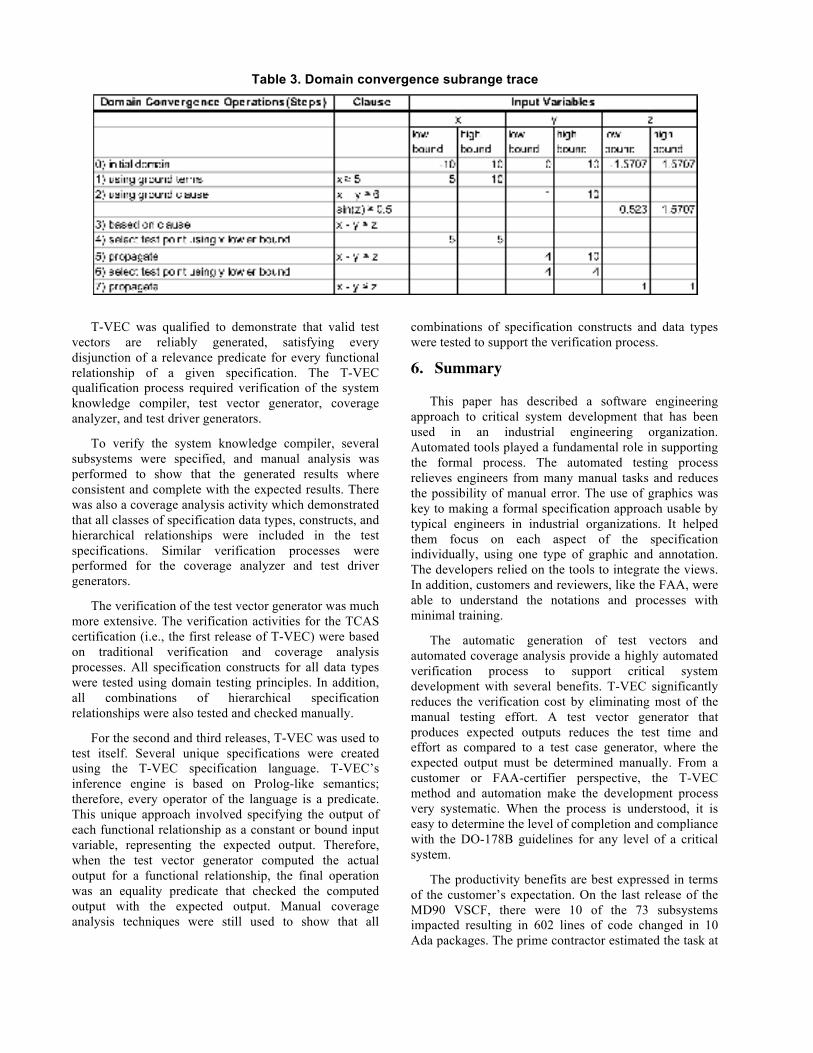
Table 3. Domain convergence subrange trace
T-VEC was qualified to demonstrate that valid test vectors are reliably generated, satisfying every disjunction of a relevance predicate for every functional relationship of a given specification. The T-VEC qualification process required verification of the system knowledge compiler, test vector generator, coverage analyzer, and test driver generators.
To verify the system knowledge compiler, several subsystems were specified, and manual analysis was performed to show that the generated results where consistent and complete with the expected results. There was also a coverage analysis activity which demonstrated that all classes of specification data types, constructs, and hierarchical relationships were included in the test specifications. Similar verification processes were performed for the coverage analyzer and test driver generators.
The verification of the test vector generator was much more extensive. The verification activities for the TCAS certification (i.e., the first release of T-VEC) were based on traditional verification and coverage analysis processes. All specification constructs for all data types were tested using domain testing principles. In addition, all combinations of hierarchical specification relationships were also tested and checked manually.
For the second and third releases, T-VEC was used to test itself. Several unique specifications were created using the T-VEC specification language. T-VEC’s inference engine is based on Prolog-like semantics; therefore, every operator of the language is a predicate. This unique approach involved specifying the output of each functional relationship as a constant or bound input variable, representing the expected output. Therefore, when the test vector generator computed the actual output for a functional relationship, the final operation was an equality predicate that checked the computed output with the expected output. Manual coverage analysis techniques were still used to show that all
combinations of specification constructs and data types were tested to support the verification process.
6. Summary
This paper has described a software engineering approach to critical system development that has been used in an industrial engineering organization. Automated tools played a fundamental role in supporting the formal process. The automated testing process relieves engineers from many manual tasks and reduces the possibility of manual error. The use of graphics was key to making a formal specification approach usable by typical engineers in industrial organizations. It helped them focus on each aspect of the specification individually, using one type of graphic and annotation. The developers relied on the tools to integrate the views. In addition, customers and reviewers, like the FAA, were able to understand the notations and processes with minimal training.
The automatic generation of test vectors and automated coverage analysis provide a highly automated verification process to support critical system development with several benefits. T-VEC significantly reduces the verification cost by eliminating most of the manual testing effort. A test vector generator that produces expected outputs reduces the test time and effort as compared to a test case generator, where the expected output must be determined manually. From a customer or FAA-certifier perspective, the T-VEC method and automation make the development process very systematic. When the process is understood, it is easy to determine the level of completion and compliance with the DO-178B guidelines for any level of a critical system.
The productivity benefits are best expressed in terms of the customer’s expectation. On the last release of the MD90 VSCF, there were 10 of the 73 subsystems impacted resulting in 602 lines of code changed in 10 Ada packages. The prime contractor estimated the task at
6 months, based on software development efforts prior to this program. The specification, implementation and verification efforts were reduced to 4.5 weeks. The primary reason for the reduction in time and effort was because the test generation and execution were performed automatically. Although the actual data is proprietary, in all of the T-VEC releases to the prime contractor and customer, no defects have been found in the software.
7. Acknowledgments
The authors would like to thank Joe Fontaine, whose extensive use of T-VEC has evolved the system to more practical levels. The authors would also like to thank Tony Brintzenhoff and Bobbie Troy.
8. References
[1] Afifi, F. H., L. J. White, S. J. Zeil, Testing for linear errors in nonlinear computer programs, 14th International Conference on Software Engineering, pp. 81-91, May 1992.
[2] Busser, R. D., M. R. Blackburn, Moving structured methods towards proof of correctness, Proceedings of Structured Development Forum VIII, August 1986.
[3] Blackburn, M. R., R. D. Busser, Formal specification method and case tool environment, Invention Disclosure 542-90-003, Allied Signal, 1990.
[4] Busser, R. D., M. R. Blackburn, Specification-based test vector generator, Invention Disclosure 542-90-004, Allied Signal, 1990.
[5] Beizer, B., Software Testing Techniques, Van Nostrand Reinhold, 1983.
[6] Butler, R. W., G. B. Finelli, the infeasibility of quantifying the reliability of life-critical real-time software, IEEE Transactions on Software Engineering, 19(1):3-12, Jan. 1993.
[7] Bernot, G., M. C. Gaudel, B. Marre, Software testing based on formal specifications: a theory and a tool, Software Engineering Journal, pp. 387-405, Nov. 1991.
[8] Blackburn, M. R., Using expert systems to construct formal specifications, IEEE Expert, 4(1):62-74, Spring 1989.
[9] Busser, R. D., Formalizing a theory of real-time software specification, Software Engineering and Its Application to Avionics, NATO Advisory Group for Aerospace Research and Development, No. 439, April 1988.
[10] Craigen, D., S. Gerhart, T. Ralston, An international survey of industrial applications of formal methods, NRL/FR/5546-93-9581, September 1993.
[11] Crow, J. S. Owre, J. Rushby, N. Shankar, M. Srivas, A tutorial introduction to PVS, Workshop on Industrial-Strength Formal Specification Techniques, April 1995.
[12] Clarke, L. A. J. Hassell, D. J. Richardson, A close look at domain testing, IEEE Transaction on Software Engineering, SE 8(4):380-390, July 1982.
[13] Denney, R., Test case generation from Prolog based specifications, IEEE Software, pp. 49-57, March 1991.
[14] Ghiassi, M., K. I. S. Woldman, Dual programming approach to software testing, Software Quality Journal 3, pp. 45-59, 1994.
[15] Gourlay, J. S., Introduction to the formal treatment of testing, Software Validation, Proceeding of the Symposium on Software Validation, pp. 67-72, 1983.
[16] Hoare, C. A. R., An axiomatic basis for computer programming, Communications of the ACM, 12(10):576-583, October 1969.
[17] Howden, W.E. Reliability of the path analysis testing strategy, IEEE Transactions on Software Engineering, SE-2(3):208-215, Sept. 1976.
[18] Jeng, B., E. J. Weyuker: A simplified domain-testing strategy, ACM Transactions on Software Engineering and Methodology 3(3):254-270, July 1994.
[19] Jones, C. B., Systematic software development using VDM, Prentice-Hall International Series in Computer Science, Prentice-Hall, 1986.
[20] Leveson, N. G., Software safety: what, why, and how. ACM Computing Surveys, 18(2): 126-163, June 1986.
[21] Miller, D. R., The role of statistical modeling and inference in software quality assurance, In Bernard de Neumann, editor, Software Certification, Chapter 10, Elsevier Applied Science, London, 1989.
[22] Poston, R M., Automated testing from object models, Communications of the ACM, September, pp. 48-58, 1994.
[23] Richardson, D. J., O. O’Malley, C. Tittle, Approaches to specification-based testing, ACM SIGSoft 89: Third Symposium on Software Testing, Analysis and Verification, December 1989.
[24] RTCA/DO178B, Software considerations in airborne systems and equipment certification, Requirements and Technical Concepts for Aviation, Washington, D.C., December 1992. EUROCAE ED12B in Europe.
[25] Rushby, J., Formal methods and the certification of critical system, Technical Report CSL-93-07, Computer Science Laboratory, SRI International, November 1993.
[26] Stocks, P.A., D.A. Carrington, Test templates: a specification-based testing framework, 15th International Conference on Software Engineering, pp. 405-414, May 1993.
[27] Spivey, J. M., Understanding Z: A specification language and its formal semantics, Cambridge Tracts in Theoretical Computer Science, Cambridge University Press, 1988.
[28] Tsai, W. T., D. Volovik, T. F. Keefe, Automated test case generation for programs specified by relational algebra queries, IEEE Transactions on Software Engineering, 16(3):316-324, March 1990.
[29] White, L. J., E. I. Cohen, A domain strategy for computer program testing, IEEE Transactions on Software Engineering, Vol. SE6( 3):247-257, May 1980.
[30] Zeil, S. J., F. H. Afifi, L. J. White, Detection of linear errors via domain testing, ACM Transaction on Software Engineering and Methodology, 1(4). 422-451, Oct. 1992.
[31] Zeil, S. J., Perturbation techniques for detecting domain errors, IEEE Transactions on Software Engineering, (15)6:737-746, June 1989.
![County Louth VEC and County Monaghan VEC · 2017. 9. 11. · County Louth VEC and County Monaghan VEC MATHEMATICS [5N1833] 6 2.6 Solve simple probability problems of one or two events](https://img.pdfslide.us/doc/110x75/5fcb5a368ca97e7cd6728991/county-louth-vec-and-county-monaghan-2017-9-11-county-louth-vec-and-county.jpg)