Embed Size (px)
Citation preview

¢T,
u_
!
0
<
<Z
MEMO 1-i 1-59E
NASA
MEMORANDUM
EXPERIMENTAL INVESTIGATION OF AERODYNAMIC EFFECTS OF
EXTERNAL COMBUSTION IN AIRSTREAM BELOW TWO-
DIMENSIONAL SUPERSONIC WING AT
MACH 2.5 AND 3.0
By Robert G. Dorsch, John S. Serafini, Edward A. Fletcher
and I. Irving Pinkel
Lewis Research Center
Cleveland, OhioI
._, h
L'iL _,
NATIONAL AERONAUTICS ANDSPACE ADMINISTRATION
wAs,-,,.GToN __ "'" Ji_.March 1959 _"-;_. J, _J :
https://ntrs.nasa.gov/search.jsp?R=19980228308 2018-08-31T03:02:33+00:00Z
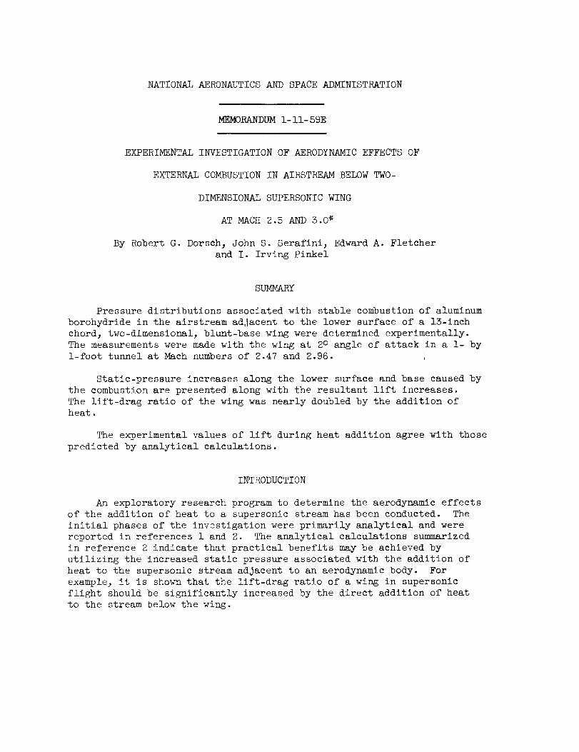
NATIONAL AERONAUTICS AND SPACE ADMINISTRATION
MEMORANDUM I- II- 59E
EXPERIMENTAL INVESTIGATION OF AERODYNAMIC EFFECTS OF
EXTERNAL COMBUSTION IN AIRSTREAM BELOW TWO-
DIMENSIONAL SUPERSONIC WING
AT MACH 2.5 AND 5.0 _
By Robert G. Dorsch_ John S. Serafinij Edward A. Fletcher
and I. Irving Pinkel
SUMMARY
Pressure distributions associated with stable combustion of aluminum
borohydride in the airstream adjacent to the lower surface of a 13-inch
chord 3 two-dimensional_ blunt-base wing were determined experimentally.
The measurements were made with the wing at 2° angle of attack in a i- by
1-foot tunnel at Mach numbers of 2.47 and 2.96.
Static-pressure increases along the lower surface and base caused by
the combustion are presented along with the resultant lift increases.
The lift-drag ratio of the wing was nearly doubled by the addition of
heat.
The experimental values of lift during heat addition agree with those
predicted by analytical calculations.
INTRODUCTION
An exploratory research program to determine the aerodynamic effects
of the addition of heat to a supersonic stream has been conducted. The
initial phases of the investigation were primarily analytical and were
reported in references i and 2. The analytical calculations summarized
in reference 2 indicate that practical benefits may be achieved by
utilizing the increased static pressure associated with the addition of
heat to the supersonic stream adjacent to an aerodynamic body. For
example, it is shown that the lift-drag ratio of a wing in supersonic
flight should be significantly increased by the direct addition of heat
to the stream below the wing.
2
The next phase of the study was primarily concerned with findinga method of adding heat directly to the stream. In the experimentalresearch reported in references 3 and 4 it _as found that aluminumboro-hydride injected into the high velocity stream adjacent to the top wallof a supersonic wind tunnel would burn stably upon ignition. No flame-holders_ other than the tunnel wall and its associated boundary layer_were necessary to stabilize the combustion.
In the present phase of the investigatLon the techniques of references3 and 4 are being employedto obtain exter_l combustion adjacent toseveral aerodynamic bodies in a small (i- by l-ft) supersonic wind tunnelin order to study the aerodynamic effects o? heat addition. The aerody-namic effects produced by the combustion of aluminumborohydride in aMach2.46 airstream adjacent to a 13-inch and a 25-inch flat-plate modelare summarizedin reference 5. The results obtained with a body of re-volution at Mach2.47 are given in referenc,_ 6.
The results obtained with a third model., a two-dimensional, 6-percentthick, blunt-base supersonic wing are preselted in this report. Reference7 showed that the low-drag airfoil section (306-T) chosen had goodaerodynamic characteristics at the Machnumbersemployed in this in-vestigation. The results will therefore inlicate the lift-drag-ratio(L/D) improvementpossible whenheat is added below a conventionalwing which initially has good aerodynamic qualities. As in the previousexperimental studies_ the heat addition was accomplished by burningaluminumborohydride in the adjacent supers(nic stream. The location ofthe heat-addition region below the wing was arbitrarily chosen to provideprimarily a lift increase rather than a drawlreduction in order tofacilitate comparison with the theoretical (alculations of reference 2.
This report summarizesthe statie-presEure changes at the wing sur-face caused by external combustion of alumilum borohydride. The measure-ments were madein one of the Lewis i- by l-foot supersonic tunnels withthe wing at an arbitrary 2° angle of attack and with free-stream Maehnumbersof 2.47 and 2.96. The lift and dra_ of the wing during combustionare computedfrom the pressure data and are comparedwith the nonburningvalues. In addition_ the measuredlift coefficients are comparedwiththose calculated analytically.
APPARATUSANDPROCEDURE
The apparatus and procedures employed in this investigation are similarin manydetails to those described in reference 5. As in reference 5, ai- by 1-foot nonreturn-type supersonic tunnel was employed. Aluminumborohydride was burned for 2- to 3-second periods below the lower surfaceof a two-dimensional wing. The tests were conducted at free-stream Machnumbersof 2.47 and 2.96.
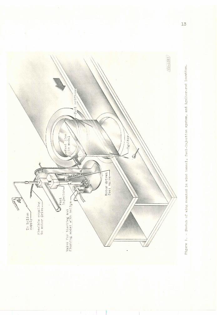
Model and Instrumentation
The two-dimensional wing model was installed in the test section ata 2° angle of attack in the vertical plane as shownin figure I. Inorder to facilitate direct and schlieren photographyj the model wasmountedacross the schlieren window of the tunnel by attaching it to thewindow retaining rings. The coordinates of the airfoil section (approx-imately circular arc with blunted trailing edge) are given in table I.Other pertinent dimensions of the model are:
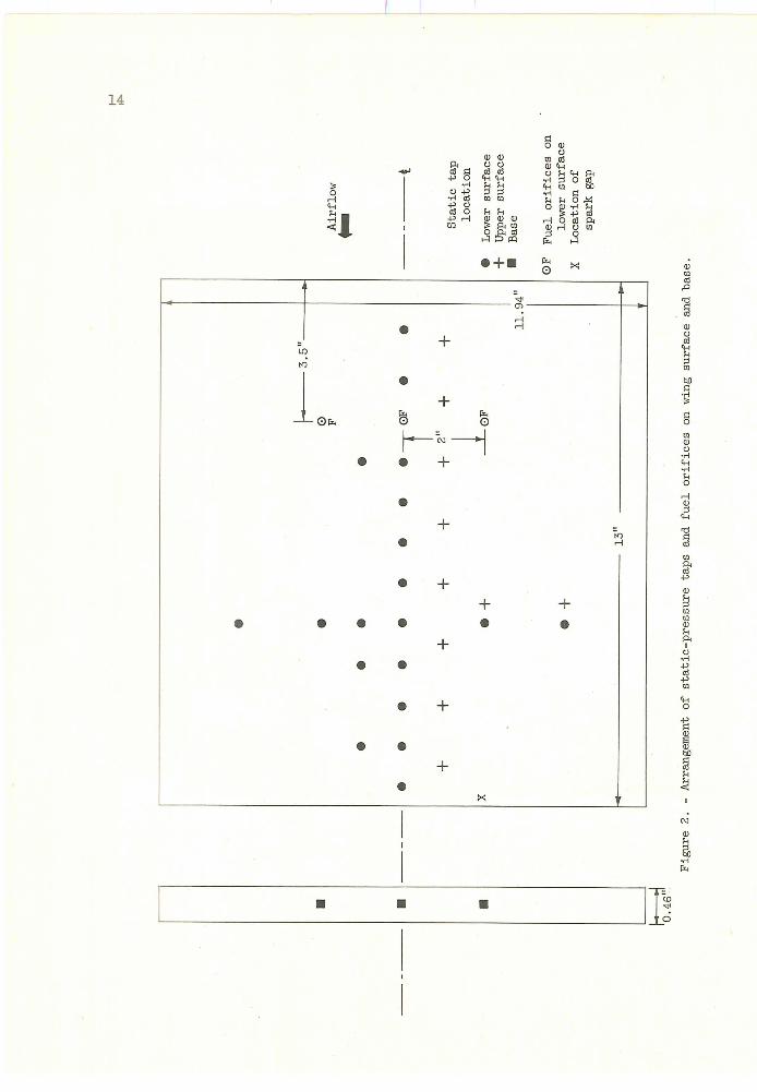
Maximumthickness to chord ratio ................. 0.06Chord length, in .......................... ISSpan, in ............................. 11.94Maximumthickness (at 67-percent chord), in ........... 0.78Blunt trailing-edge thickness_ in ................ 0.46Leading-edge angle (total included) ............... 6°59'Distance from leading edge to fuel orifices, in .......... 5.5Distance from central to outboard fuel orifices, in ........ 2.0
The arrangement of static-pressure taps on the model surface is shownin figure 2. Rather large static orifice diameters (0.048 in.) were usedto reduce the possibility of plugging by ash deposits on the model sur-face resulting from the external combustion.
The static pressures in the absence of combustion were measuredwithdibutylphthalate differential manometerboards. Changesin wing surfaceand base static pressures causedby combustion were measuredwith strain-gage-type and NACAstandard-base six-capsule manometerdifferentialpressure transducers.
Fuel Injection and Ignition
The method of injecting fuel into the airstream adjacent to the wingwas basically similar to that described for the flat-plate model of ref-erence 5. The fuel injector (fig. l) was loaded with 25 to 35 cubiccentimeters of aluminumborohydride prior to each run and pressurizedwith helium. The liquid was injected under pressure (lO0 lb/sq in. gage)into the airstream through three fuel orifices 0.016 inch in diameterlocated in the lower surface of the model as shownin figure 2. Theinjection period was of 2- to S-seconds duration providing an averagefuel-flow rate of 12 cubic centimeters per second (0.015 lb/sec ±lOpercent) .
In order to insure prompt and reliable ignition, the fuel was ignitedwith an electric-spark-type ignitor. The ignitor rod had a i/4-inchdiameter and was positioned as shownin figure i. The spark gap betweenmodel surface and ignitor tip was located i/4 inch upstream of the base
4
and was in line _ith an outboard fuel orifice. A repeating capacitance-type power supply (1-joule energy) provided a spark from rod to modelsurface 5 times a second. In previous experimental work the ignitorrod positioned as shownin figure 1 had only a small effect on thecombustion and pressure fields.
Test Conditions and P_ocedure
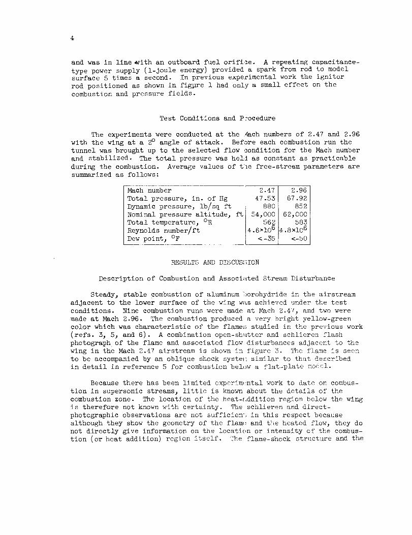
The experiments were conducted at the Machnumbersof 2.47 and 2.96with the wing at a 2° angle of attack. Before each combustion run the
tunnel was brought up to the selected flow condition for the Mach number
and stabilized. The total pressure was held as constant as practicable
during the combustion. Average values of the free-stream parameters aresummarized as follows:
Mach number
Total pressure, in. of Hg
Dynamic pressure, lb/sq ft
Nominal pressure altitude_ ft
Total temperature 3 OR
Reynolds number/ft
Dew point_ OF
2.¢7
47.55
88O
54,000562
4.62106
<-55
2.96
67.92
852
62_,000585
4.8 xlO 6
<-50
RESULTS AND DISCUS;_ION
Description of Combustion and Associ_ted Stream Disturbance
Steadyj stable combustion of aluminum :_orohydride in the airstream
adjacent to the lower surface of the wing w_s achieved under the test
conditions. Nine combustion runs were made at Mach 2.47, and two were
made at Mach 2.96. The combustion produced a very bright yellow-green
color which was characteristic of the flame:_ studied in the previous work
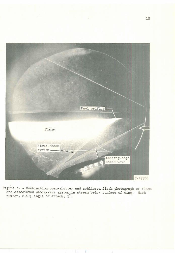
(refs. 5_ 5_ and 6). A combination open-shlttter and schlieren flash
photograph of the flame and associated flow disturbances adjacent to the
wing in the Mach 2.47 airstream is shown in figure 3. The flame is seen
to be accompanied by an oblique shock systeI_ similar to that described
in detail in reference 5 for combustion bel_w a flat-plate model.
Because there has been limited experim_ntal work to date on combus-
tion in supersonic streams, little is known about the details of the
combustion zone. The location of the heat-_.ddition region below the wing
is therefore not known with certainty. The schlieren and direct-
photographic observations are not sufficien-, in this respect because
although they show the geometry of the flam_ and t!_e heated flow_ they do
not directly give information on the location or intensity of the combus-
tion (or heat addition) region itself. The flame-shock structure and the
chordwise pressure-change profile caused by the heat addition (discussedin the next section) are most useful in defining the heat-addition region.They suggest that strong combustion took place in the upstream portionof the flame (within 1 or 2 in. of the fuel orifices) followed by arapidly decreasing rate of combustion with distance downstream. Inadditionj visual observations of the flame far downstreamof the baseindicated that part of the fuel mayhave burned in the wake rather thanbelow the wing. The schlieren photographs indicate that at both Machnumbersthe shock waves from the leading edge of the wing and from theflame are reflected from the tunnel walls in such a manner that theycross the centerline of the tunnel downstreamof the base in the heated-wake region of the wing. For the Mach2.96 condition, the points ofintersection of the shock waveswith the wake are, of course, furtherdownstreamfrom the base than at Mach2.47. For this reason only theMach 2.96 base-pressure-change data are presented in the next section.
Static- and Base-Pressure ChangesCausedby Combustion
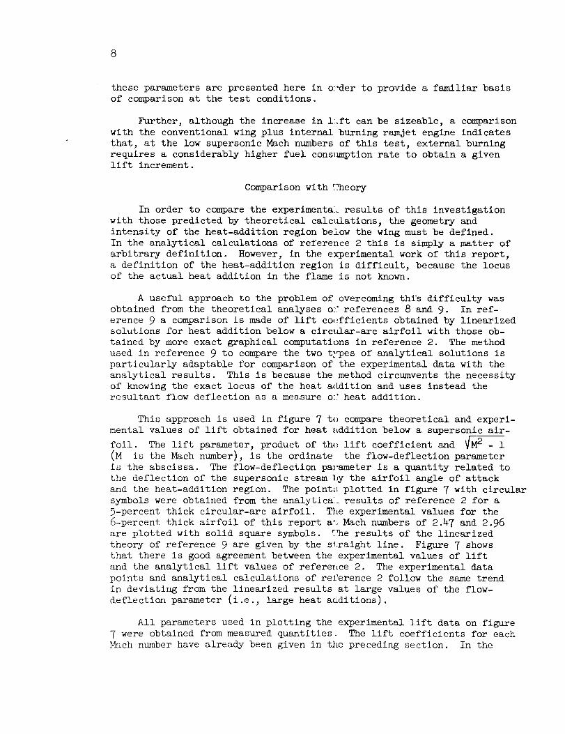
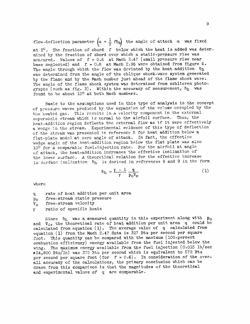
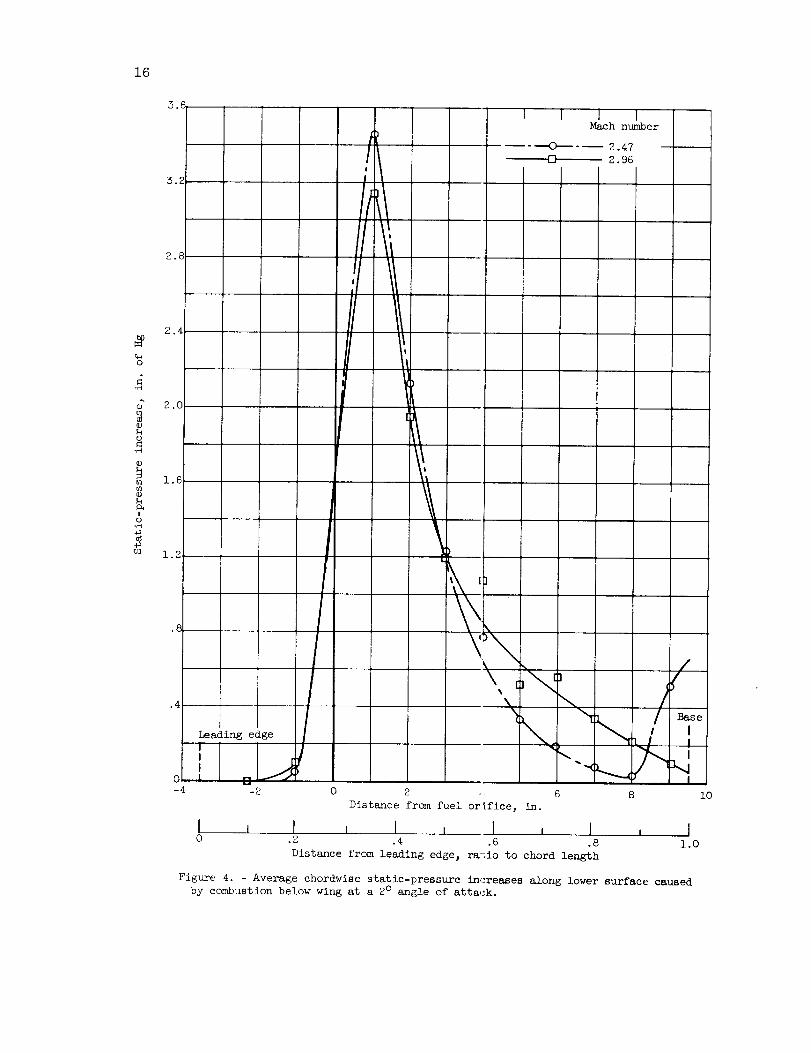
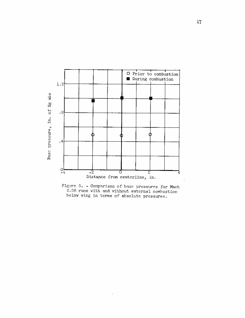
The external combustion in the stream below the wing caused an in-crease in local static pressure along the lower surface and base.Average values (for all runs at each Machnumber) of the local static-pressure increases for the two Machnumberconditions are given infigures 4 and 5. Figure 4 shows the centerline chordwise pressure-changeprofiles along the lower surface of the wing for Mach2.47 and 2.96.The chordwise distributions of static-pressure increase caused by thecombustion are generally similar for the two Machnumbers. 0nly in thelast inch before the base is there a significant difference in the shapeof the two curves. The base pressures for the Mach2.96 runs with andwithout combustion are shownin figure 5. The increase in base pressurecaused by the combustion was about I00 percent.
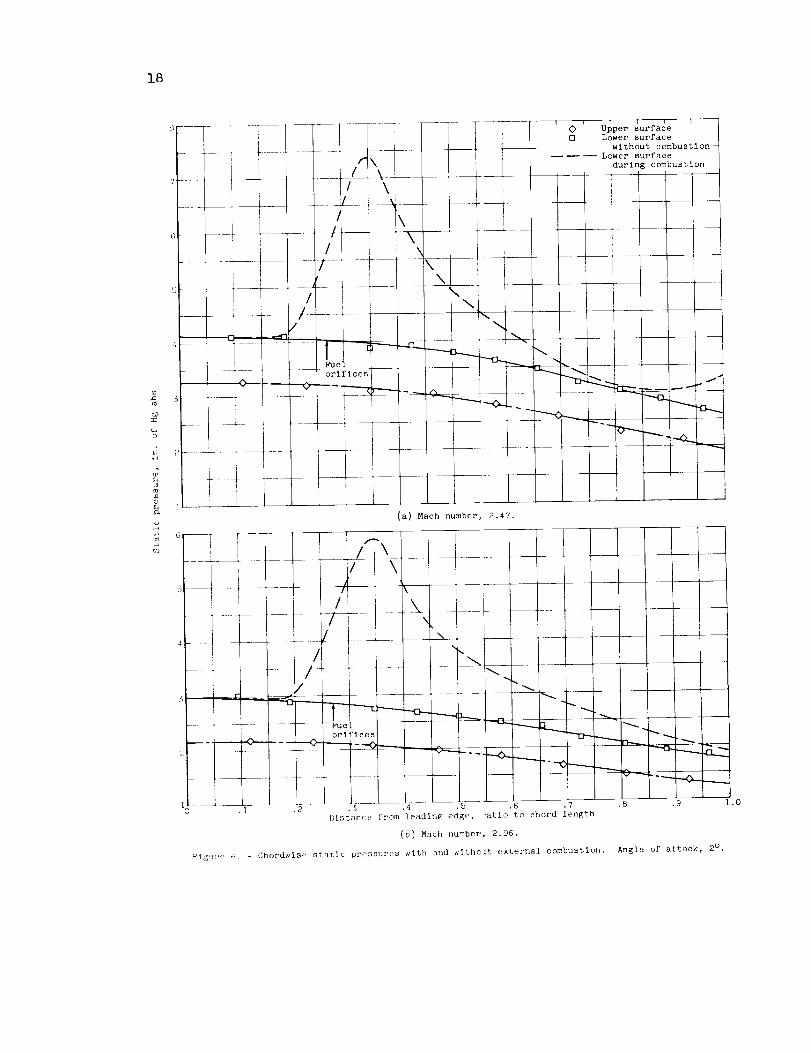
The chordwise static-pressure profiles along the upper and lowersurfaces of the wing with and without combustion are shownin figure 6.The Mach2.47 data are shownin figure 6(a), and the Mach2.96 data areshownin figure 6(b). The lower-surface static pressures during combus-tion were obtained by adding the average pressure changes caused by thecombustion (fig. 4) to the corresponding static pressures without combus-tion. The upper-surface static pressures were not changedby the combus-tion. The measurementsmadeat the spanwise station located 5 inchesdownstreamof the fuel orifice (fig. 2) indicated that the static pressure

during combustion was approximately constant in the spanwise direction.Similar results were obtained with the flat-plate models of reference 5,which had identical fuel-orifice geometry.
The presence of reflected shock waves in the heated wake region ofthe wing requires that the pressure-change data be carefully inspectedfor any signs of wind-tunnel effects. With the exception of the smallarea just upstream of the base in the Math _.47 data of figure 4 (whichwill not be included in the lift calculatiors of the next section), theshape of the chordwise pressure-change distributions at both Math numbersindicates that the static-pressure changesalong the lower surface werenot influenced by tunnel effects.
Lift and Drag Calculations
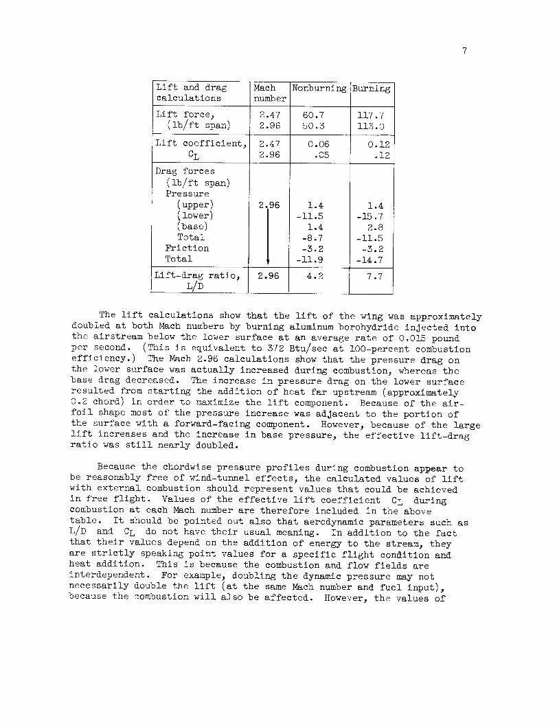
The lift and drag forces on the wings zesulting from the surface-and base-pressure distribution can be calculated from the static-pressuredata obtained with and without combustion ir order to obtain an appraisalof the aerodynamic effects of external combustion. For simplicity_ thelift and drag force componentson the model will generally be presenteddirectly in terms of pounds of force occurring on the model at the testconditions. Lift calculations were madefor both Machnumbers. The dragcalculations were madeonly for the Math 2.96 runs.
For the calculations the pressure in the spanwise direction will beassumedconstant at each chordwise station. As discussed previously, thisis a reasonable assumption with the exceptiom of a small area in thevicinity of the fuel orifices where the pressure field is, of course_more variable.
The lift and pressure-drag per foot span for the wing with and with-out external combustion were calculated from the data of figures 5 and 6.The noi_urning friction drag was calculated from a skin-friction coeffi-cient (based on plan form area) of 0.0055 o_tained from unpublished wind-tunnel tests of this airfoil. During combustion the skin-friction coeffi-cient was arbitrarily assumedto be the sameas the nonburning value.The lift and drag calculations are summarize_in the following table inwhich a positive force componentindicates a_ upstream or thrust component,and a negative one indicates a downstreamor drag component.
Lift and dragcalculations
Lift force,(ib/ft span)
Lift coefficient,CL
Drag forces(ib/ft span)Pressure
(upper)(lower)(base)Total
Friction
Total
Math
numberNonburning Burning
2.47 60.7 117.7
2.96 50.3 i15.0
0.06
.05
1.4
-ii.5
1.4
-8.7
-3.2
-ii.9
2.96 1.4
-15.7
2.8
-II.5
-3.2
-14.7
0.12
.12
Lift-drag ratio_ 2.96 4.2 7.7
L/D
The lift calculations show that the lift of the wing was approximately
doubled at both Mach numbers by burning aluminum borohydride injected into
the airstream below the lower surface at an average rate of 0.015 pound
per second. (This is equivalent to 372 Btu/sec at lO0-percent combustion
efficiency°) The Mach 2.96 calculations show that the pressure drag on
the lower surface was actually increased during combustion, whereas the
base drag decreased. The increase in pressure drag on the lower surface
resulted from starting the addition of heat far upstream (approximately
0.2 chord) in order to maximize the lift component. Because of the air-
foil shape most of the pressure increase was adjacent to the portion of
the surface with a forward-facing component. However, because of the large
lift increases and the increase in base pressure, the effective lift-drag
ratio was still nearly doubled.
Because the chordwise pressure profiles during combustion appear to
be reasonably free of wind-tunnel effects, the calculated values of lift
with external combustion should represent values that could be achieved
in free flight. Values of the effective lift coefficient CL duringcombustion at each Mach number are therefore included in the above
table. It should be pointed out also that aerodynamic parameters such as
L/D and CL do not have their usual meaning. In addition to the fact
that their values depend on the addition of energy to the stream, they
are strictly speaking point values for a specific flight condition andheat addition. This is because the combustion and flow fields are
interdependent. For example, doubling the dynamic pressure may not
necessarily double the lift (at the same Mach number and fuel input),
because the _ombustion will also be affected. However, the values of
8
these parameters are presented here in o:_'der to provide a familiar basis
of comparison at the test conditions.
Further, although the increase in l_,ft can be sizeable, a comparison
with the conventional wing plus internal burning ramjet engine indicates
that, at the low supersonic Mach numbers of this test, external burning
requires a considerably higher fuel cons_uption rate to obtain a givenlift increment.
Comparison with ¶_heory
In order to compare the experimental results of this investigation
with those predicted by theoretical calculations, the geometry and
intensity of the heat-additlon region below the wing must be defined.
In the analytical calculations of reference 2 this is simply a matter of
arbitrary definition. However, in the experimental work of this report,
a definition of the heat-addition region is difficult, because the locusof the actual heat addition in the flame is not known.
A useful approach to the problem of overcoming thfs difficulty was
obtained from the theoretical analyses oL_ references 8 and 9. In ref-
erence 9 a comparison is made of lift co,_fficients obtained by linearized
solutions for heat addition below a circ1_ar-arc airfoil with those ob-
tained by more exact graphical computations in reference 2. The method
used in reference 9 to compare the two t_es of analytical solutions is
particularly adaptable for comparison of the experimental data with the
analytical results. This is because the method circumvents the necessity
of knowing the exact locus of the heat addition and uses instead the
resultant flow deflection as a measure o_" heat addition.
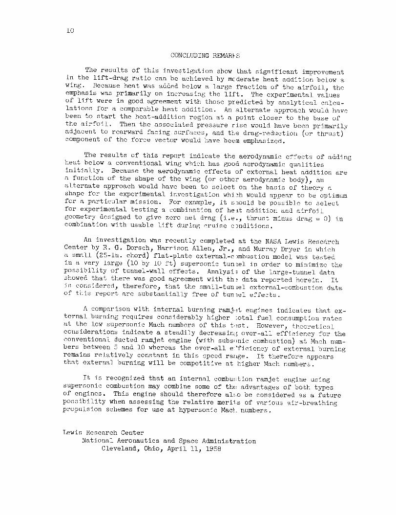
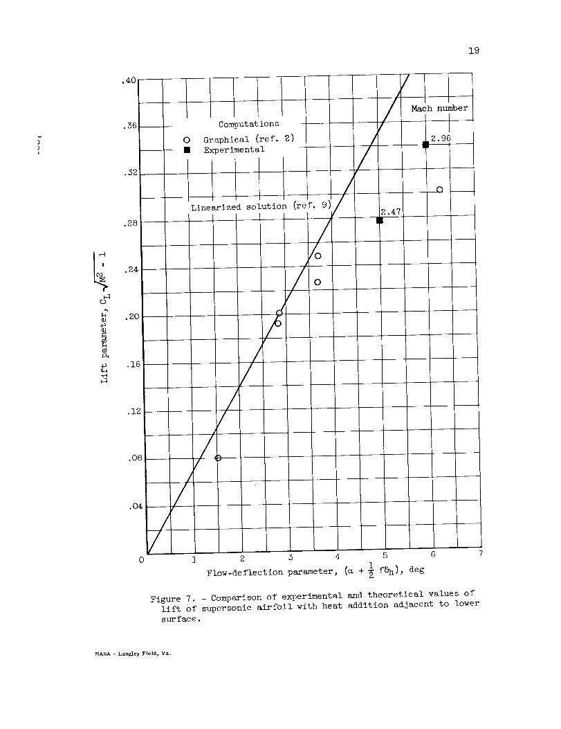
This approach is used in figure 7 t(, compare theoretical and experi-
mental values of lift obtained for heat addition below a supersonic air-
foil. The lift parameter, product of th_ llft coefficient and _- 1
(M is the Mach number), is the ordinate the flow-deflection parameter
is the abscissa. The flow-deflection pa]'ameter is a quantity related to
the deflection of the supersonic stream by the airfoil angle of attack
and the heat-addition region. The point_ plotted in figure 7 with circular
symbols were obtained from the analytical, results of reference 2 for a
5-percent thick circular-arc airfoil. T]Le experimental values for the
6-percent thick airfoil of this report a_. Mach numbers of 2.47 and 2.96
are plotted with solid square symbols. E!he results of the linearized
theory of reference 9 are given by the straight llne. Figure 7 shows
that there is good agreement between the experimental values of lift
and the analytical lift values of refereI_ce 2. The experimental data
points and analytical calculations of reference 2 follow the same trend
in deviating from the linearized results at large values of the flow-
deflection parameter (i.e., large heat a_ditions).
All parameters used in plotting the experimental lift data on figure
7 were obtained from measured quantities° The lift coefficients for each
Mach number have already been given in tlm preceding section. In the
9
flow-deflection parameter _ \I_ + ifS__ the angle of attack _ was fixed\ 72
at 2° . The fraction of chord f below which the heat is added was deter-mined by the fraction of chord over which a static-pressure rise wasmeasured. Values of f = 0.6 at Mach2.A7 (small pressure rise nearbase neglected) and f = 0.8 at Mach2.96 were obtained from figure 6.The angle through which the flow was deviated by the heat addition 8hwas determined from the angle of the oblique shock-wavesystem generatedby the flame and by the MachnumberJust ahead of the flame shock wave.The angle of the flame shock system was determined from schlieren photo-graphs (such as fig. 3). Within the accuracy of measurement38h wasfound to be about i0 ° at both Machnumbers.
Basic to the assumptions used in this type of analysis is the conceptof pressure waves produced by the expansion of the volume occupied by thethe heated gas. This results in a velocity componentin the externalsupersonic stream which is normal to the airfoil surface. Thus3 theheat-addition region deflects the external flow as if it were effectivelya wedge in the stream. Experimental evidence of this type of deflectionof the stream was presented in reference 5 for heat addition below aflat-plate model at zero angle of attack. In fact, the effectivewedgeangle of the heat-addition region below the flat plate was alsolO° for a comparable fuel-injectlon rate. For the airfoil at angleof attack_ the heat-addition increases the effective inclination ofthe lower surface. A theoretical relation for the effective increasein surface inclination 8h is derived in references 8 and 9 in the form
- r - I q (I)PoVo
where
q
Po
Vo
Y
rate of heat addition per unit area
free-stream static pressure
free-stream velocity
ratio of specific heats
Since 5h was a measured quantity in this experiment along with Po
and Vo_ the theoretical rate of heat addition per unit area q could be
calculated from equation (1). The average value of q calculated from
equation (1) from the Mach 2.47 data is 327 Btu per second per square
foot. This quantity can be compared with the maximum (lO0-percent
combustion efficiency) energy available from the fuel injected below the
wing. The maximum energy available from the fuel injection (0.015 lb/sec
243800 Btu/lb) was 372 Btu per second which is equivalent to 572 Btu
per second per square foot (for f = 0.6). In consideration of the over-
all accuracy of the calculations3 the primary conclusion which can be
drawn from this comparison is that the magnitudes of the theoretical
and experimental values of q are comparable.
lO
CONCLUDINGREMAR_S
The results of this investigation show that significant improvementin the lift-drag ratio can be achieved by mcderate heat addition below awing. Becauseheat was addedbelow a large fraction of the airfoil, theemphasis was primarily on increasing the lift. The experimental valuesof lift were in good agreementwith those predicted by analytical calcu-lations for a comparable heat addition. An alternate approach would havebeen to start the heat-addition region at a point closer to the base ofthe airfoil. Then the associated pressure rise would have been primarilyadjacent to rearward facing surfaces, and the drag-reduction (or thrust)componentof the force vector would have beememphasized.
The results of this report indicate the aerodynamic effects of addingheat below a conventional wing which has good aerodynamic qualitiesinitially. Becausethe aerodynamic effects of external heat addition area function of the shape of the wing (or other aerodynamic body), analternate approach would have been to select on the basis of theory ashape for the experimental investigation which would appear to be optimumfor a particular mission. For example, it s_ould be possible to selectfor experimental testing a combination of he_t addition and airfoilgeometry designed to give zero net drag (i.e., thrust minus drag = O) incombination with usable lift during cruise c_nditious.
An investigation was recently completed at the NASALewis ResearchCenter by R. G. Dorsch3 Harrison Allen, Jr._ and Murray Dryer in whicha small (25-iu. chord) flat-plate external-c_mbustion model was te_tedin a very large (i0 by I0 ft) supersonic tunnel in order to minimize thepossibility of tunnel-wall effects. Analysi_ of the large-tunnel datashewedthat there was good agreementwith th_ data reported herein. Itis considered_ therefore, that the small-tunlel external-combustion dataof t}iis report are substantially free of tunnel effects.
A comparison with internal burning ramjet engines indicates that ex-ternal burning requires considerably higher _otal fuel consumption ratesat the low supersonic Machnumbersof this t._st. However, theoreticalconsiderations indicate a steadily decreasini_ over-all efficiency for theconventional ducted ramjet engine (with subs_mic combustion) at Machnum-bers between S and I0 whereas the over-all e_'ficiency of external burningremains relatively constant in this speed ral_ge. It therefore appearsthat external burning will be competitive at higher Machnumbers.
It is recognized that an internal combu_tion ramjet engine usingsupersonic combustion maycombine someof th_ advantages of both typesof engines. This engine should therefore al_o be considered as a futurepossibility when assessing the relative merils of various air-breathingpropulsion schemesfor use at hypersonic Macl numbers.
Lewis Research CenterNational Aeronautics and SpaceAdministration
Cleveland, 0hio_ April II, 1958
Ii
REFERENCES
i. Pinkel_ I. Irving_ and Serafini_ John S.: Graphical Method for Ob-taining Flow Field in Two-Dimensional Supersonic Stream to WhichHeat Is Added. NACATN 2206_1950.
2. Pinkel 3 I. Irving_ Serafini_ John S._ and Gregg_ John L.: PressureDistribution and Aerodynamic Coefficients Associated with HeatAddition to Supersonic Air Stream Adjacent to Two-DimensionalSupersonic Wing. NACARMESIK26_1952.
3. Fletcher_ EdwardA.3 Dorsch3 Robert G._ and Gerstein_ Melvin: Combus-tion of AluminumBorohydride in a Supersonic Wind Tunnel. NACARME55DO7a_ 1955.
4. Dorsch_ Robert G._ Serafini_ John S._ and Fletcher_ Edward A.: A
Preliminary Investigation of Static-Pressure Changes Associated
with Combustion of Aluminum Borohydride in a Supersonic Wind Tunnel.
NACA RM E55F07_ 1955.
5. Dorsch_ Robert G._ Serafini_ John S. 3 and Fletcher_ Edward A.:
Exploratory Investigation of Aerodynamic Effects of External Com-
bustion of Aluminum Borohydride in Airstream Adjacent to Flat Plate
in Mach 2._6 Tunnel. NACA RM E57EI6_ 1957.
6. Serafini_ John S._ Dorsch_ Robert G._ and Fletcher 3 Edward A.:
Exploratory Investigation of Static- and Base-Pressure Increases
Resulting from Combustion of Aluminum Borohydride Adjacent to Body
of Revolution in Supersonic Wind Tunnel. NACA RM E57EI5_ 1957.
7. Syvertson 3 Clarence A. 3 and Gloria_ Hermilo R.: An Experimental In-
vestigation of the Zero-Lift-Drag Characteristics of Symmetrical
Blunt-Trailing-Edge Airfoils at Mach Numbers from 2.7 to 5.0.
NACA RM A53B02_ 1953.
8. Chu_ Boa-Teh: Pressure Waves Generated by Addition of Heat in a
Gaseous Medium. NACA _i_ 3AII_ 1955.
9. Gazley_ Carl_ Jr.: Linearized Solution for Heat Addition at the Sur-
face of a Supersonic Airfoil. RM-1892_ Rand Corp._ Nov. 213 1956.
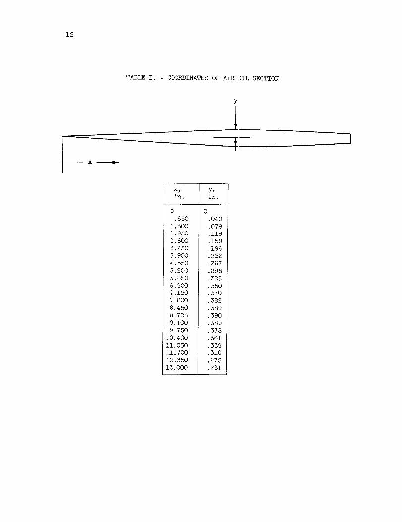
12
TABLE I. COORDINATES OF AIRF )IL SECTION
x m_D-
x, y,
in. in.
0 0
.650 .040
1.300 .079
1.950 .119
2.6OO .159
3.250 .196
5.900 .252
4.550 .267
5.200 .298
5.850 .326
6.500 .550
7.150 .570
7.800 .382
8.450 .589
8.723 .390
9.1OO .589
9.750 .578
10.400 .561
11.050 .559
11.700 .510
12.350 .275
13.000 .251
16
o
jJ
©
4J
3.2
2.
2..
2.0
1.6
1.2
/l I I I
Mach number
- _ - 2.47
{3 2.96
/IILeading edgell i
o I __'J-4 -2 0 2
]<
.: 6 8 I0
Distance from fuel orifice, in.
l i I , l l l , I , l0 .2 .4 .6 .8 1.0
Distance from leading edge, raLio to chord length
Figure 4. - Average chordwise static-pressure increases along lower surface caused
by combustion below wing at a 2 ° angle of attack.
17
1.2
I ? r
0 Prior to combustion
• During combustion
bD
0
d
J
d
.8
.4
() (
I HIII
_4 -2 2 4
Distance from centerline, in.
Figure 5. Comparison of base pressures for Mach
2.96 runs with and without external combustion
below wing in terms of absolute pressures.
18
2
%
ko
_1--[ --
4-. _ -k
_1 ......
.... ---. - .._ _....._
I2 ___-Z2.2 .,% ,4 .5 .6 .7
l)[stance from leading edge, -atlo to chord length
(b) Mach number, 2.96.
I I r I I
Upper surface
Lower Burfaoe
without combustion
------Lower _urface
during combustion
.8 .9 1.0
F"[gur_, 6- - Chordwlse static pressures with and w_the_t external combust[on. Angle of attack, 9o.
0
©©
•4O
.56 --
•52
.28
.24
.20
•16
.O4
0
19
0
//
Corn _ut at ions -
Graphical (ref. 2)
Experimental
Linearized solution
/
(ref. 9)
?/
/
0
/
/
Nach
/,I
2.47!
i 2 $ 4 5 6
i f_), degFlow-deflection p_rameter, (_ +
number
,,2.96
0
Figure 7. - Comparison of experimental and theoretical values of
lift of supersonic airfoil with heat addition adjacent to lower
surface.
NASA - Langley Field, Va.