Embed Size (px)
Citation preview
T range motors
R o t a t i n g E l e c t r i c a l M a c h i n e s
Frames 56 to 355
2801E
2801E Issue 2e T range motors
T range motors56 to 355
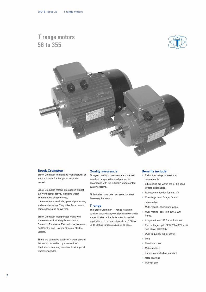
Brook Crompton
Brook Crompton is a leading manufacturer of
electric motors for the global industrial
market.
Brook Crompton motors are used in almost
every industrial activity including water
treatment, building services,
chemical/petrochemicals, general processing
and manufacturing. They drive fans, pumps,
compressors and conveyors.
Brook Crompton incorporates many well
known names including Brook Motors,
Crompton Parkinson, Electrodrives, Newman,
Bull Electric and Hawker Siddeley Electric
Motors.
There are extensive stocks of motors around
the world, backed-up by a network of
distributors, ensuring excellent local support
wherever needed.
Quality assurance
Stringent quality procedures are observed
from first design to finished product in
accordance with the ISO9001 documented
quality systems.
All factories have been assessed to meet
these requirements.
T range
The Brook Crompton ‘T’ range is a high
quality standard range of electric motors with
a specification suitable for most industrial
applications. It covers outputs from 0.06kW
up to 250kW in frame sizes 56 to 355L.
Benefits include:
• Full output range to meet your
requirements
• Efficiencies are within the EFF2 band
(where applicable).
• Robust construction for long life
• Mountings: foot, flange, face or
combination
• Multi-mount - aluminium range
• Multi-mount - cast iron 160 & 200
frame.
• Integrated feet 225 frame & above.
• Euro voltage: up to 3kW 230/400V; 4kW
and above 400/690V
• Dual frequency (50 or 60Hz)
• IP55
• Metal fan cover
• Metric entries
• Thermistors fitted as standard
• NTN bearings
• Inverter duty
2
2801E Issue 2e T range motors
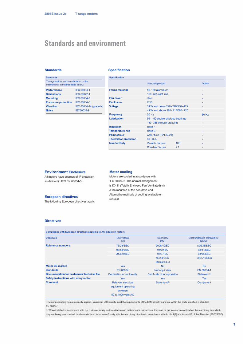
Directives
Standards Specification
Performance IEC 60034-1
Dimensions IEC 60072-1
Mounting IEC 60034-7
Enclosure protection IEC 60034-5
Vibration IEC 60034-14 (grade N)
Noise IEC60034-9
Standards
Frame material
Fan cover
Enclosure
Voltage
Frequency
Lubrication
Insulation
Temperature rise
Paint colour
Thermistor protection
Inverter Duty
56- 160 aluminium
160 - 355 cast iron
steel
IP55
3 kW and below 220 - 240/380 - 415
4 kW and above 380 - 415/660 - 720
50 Hz
56 - 160 double-shielded bearings
180 - 355 through greasing
class F
class B
water blue (RAL 5021)
56 - 355
Variable Torque: 10:1
Constant Torque: 2:1
-
-
-
-
-
-
60 Hz
-
-
-
-
-
-
-
-
OptionStandard product
Specification
3
Standards and environment
Reference numbers
Motor CE marked
Standards
Documentation for customers’ technical file
Safety instructions with every motor
Comment
Compliance with European directives applying to AC induction motors
73/23/EEC
93/68/EEC
2006/95/EC
Yes
EN 60034
Declaration of conformity
Yes
Relevant electrical
equipment operating
between
50 to 1000 volts AC
Directives Low voltage
(LV)
2006/42/EC
98/79/EC
98/37/EC
93/44/EEC
89/392/EEC
No
Not applicable
Certificate of incorporation
Yes
Statement(2)
Machinery
(MD)
89/336/EEC
92/31/EEC
93/68/EEC
2004/108/EC
No
EN 60034-1
Statement(1)
Yes
Component
Electromagnetic compatibility
(EMC)
(1) Motors operating from a correctly applied, sinusoidal (AC) supply meet the requirements of the EMC directive and are within the limits specified in standard
EN 60034-1
(2) When installed in accordance with our customer safety and installation and maintenance instructions, they can be put into service only when the machinery into which
they are being incorporated, has been declared to be in conformity with the machinery directive in accordance with Article 4(2) and Annex IIB of that Directive (98/37/EEC)
T range motors are manufactured to the
international standards listed below:
Environment Enclosure
All motors have degrees of IP protection
as defined in IEC EN 60034-5.
European directives
The following European directives apply:
Motor cooling
Motors are cooled in accordance with
IEC 60034-6. The normal arrangement
is IC411 (Totally Enclosed Fan Ventilated) via
a fan mounted at the non-drive end.
Alternative methods of cooling available on
request.
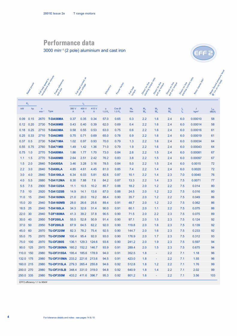
Performance data3000 min–1 (2 pole) aluminium and cast iron
2801E Issue 2e T range motors
4 For tolerance details and notes - see pages 14 & 15
kW hp
PN
n
min–1
0.09
0.12
0.18
0.25
0.37
0.55
0.75
1.1
1.5
2.2
3.0
4.0
5.5
7.5
11.0
15.0
18.5
22.0
30.0
37.0
45.0
55.0
75.0
90.0
110.0
132.0
160.0
200.0
250.0
2670
2730
2710
2710
2730
2760
2770
2770
2840
2840
2840
2880
2900
2920
2940
2940
2940
2940
2950
2950
2970
2970
2970
2970
2980
2980
2980
2980
2980
T-DA56MA
T-DA56MB
T-DA63MA
T-DA63MB
T-DA71MA
T-DA71MB
T-DA80MA
T-DA80MB
T-DA90SA
T-DA90LA
T-DA100LA
T-DA112MA
T-DA132SA
T-DA132SB
T-DA160MA
T-DA160MB
T-DA160LA
T-DF180MA
T-DF200LA
T-DF200LB
TU-DF225M
TU-DF250M
TU-DF280S
TU-DF280MA
TU-DF315SA
TU-DF315MA
TU-DF315LA
TU-DF315LB
TU-DF355M
0.15
0.20
0.25
0.33
0.5
0.75
1.0
1.5
2.0
3.0
4.0
5.5
7.5
10
15
20
25
30
40
50
60
75
100
125
150
175
215
270
335
380 V
A
400 V
A
415 V
A
η1.0 PN
MA
MN
IAIN
MK
MN
J
kgm2
IN
0.37
0.43
0.58
0.75
1.02
1.49
1.86
2.64
3.46
4.85
6.34
8.30
11.1
14.9
21.0
28.0
34.3
41.3
55.5
67.9
82.3
100.4
136.1
160.2
195.4
233.2
279.3
348.4
433.2
0.35
0.40
0.55
0.71
0.97
1.42
1.77
2.51
3.28
4.61
6.03
7.88
10.5
14.1
20.0
26.6
32.6
39.2
52.8
64.5
78.2
95.4
129.3
152.2
185.6
221.6
265.4
331.0
411.6
0.34
0.39
0.53
0.69
0.93
1.36
1.70
2.42
3.16
4.45
5.81
7.6
10.2
13.6
19.2
25.6
31.4
37.8
50.9
62.2
75.4
92.0
124.6
146.7
178.9
213.6
255.8
319.0
396.7
57.0
62.0
63.0
65.0
70.0
71.0
73.0
76.2
78.5
81.0
82.6
84.2
85.7
87.0
88.4
89.4
90.0
90.5
91.4
92.0
92.5
93.0
93.6
93.9
94.0
94.5
94.6
94.8
95.3
2.2
2.2
2.2
2.2
2.2
2.2
2.2
2.2
2.2
2.2
2.2
2.2
2.0
2.0
2.0
2.0
2.0
2.0
2.0
2.0
2.0
2.0
2.0
2.0
1.8
1.8
1.8
1.8
1.6
6.0
6.0
6.0
6.0
6.0
6.0
6.0
6.0
6.0
6.0
7.0
7.5
7.5
7.5
7.5
7.5
7.5
7.5
7.5
7.5
7.5
7.5
7.5
7.5
7.1
7.1
7.1
7.1
7.1
2.4
2.4
2.4
2.4
2.4
2.4
2.4
2.4
2.4
2.4
2.3
2.3
2.2
2.2
2.2
2.2
2.2
2.3
2.3
2.3
2.3
2.3
2.3
2.3
2.2
2.2
2.2
2.2
2.2
0.00010
0.00014
0.00016
0.00019
0.00034
0.00043
0.00081
0.00097
0.0015
0.0020
0.0040
0.0071
0.014
0.016
0.049
0.062
0.075
0.075
0.124
0.139
0.233
0.312
0.597
0.675
1.18
1.55
1.76
2.02
3.56
Roto
r ine
rtia
WK
2
Dire
ct o
n lin
e
pull
out t
orqu
e
Dire
ct o
n lin
e
star
ting
curre
nt ra
tio
Dire
ct o
n lin
e
star
ting
torq
ue ra
tio
Pow
er fa
ctor
Effic
ienc
y
Full
load
cur
rent
at
rate
d vo
ltage
Fram
e re
fere
nce
and
size
Full
load
spe
ed in
revo
lutio
ns p
er m
inut
e
Rate
d po
wer
TypeCos Ø
1.0 PN
0.65
0.69
0.75
0.78
0.79
0.79
0.84
0.83
0.84
0.85
0.87
0.87
0.88
0.88
0.90
0.91
0.91
0.90
0.90
0.90
0.90
0.90
0.90
0.91
0.91
0.91
0.92
0.92
0.92
0.3
0.4
0.6
0.9
1.3
1.9
2.6
3.8
5.0
7.4
10.1
13.3
18.2
24.5
35.7
48.7
60.1
71.5
97.1
119.8
144.7
176.9
241.2
289.4
352.5
423.0
512.8
640.9
801.2
Full
load
torq
ue
MN
Nm
MS
MN
1.6
1.6
1.6
1.6
1.6
1.6
1.5
1.5
1.5
1.4
1.4
1.4
1.2
1.2
1.2
1.2
1.1
2.2
1.5
1.6
1.6
1.7
1.9
1.5
-
-
1.2
1.4
-
Dire
ct o
n lin
e
pull
up to
rque
LPA
dB(A)
58
58
61
61
64
64
67
67
72
72
76
77
80
80
86
86
86
89
92
92
92
93
94
94
96
96
99
99
103
Mea
n So
und
pres
sure
leve
l
@ 1
m o
n no
load
EFF2 efficiency 1.1 to 90kW
5
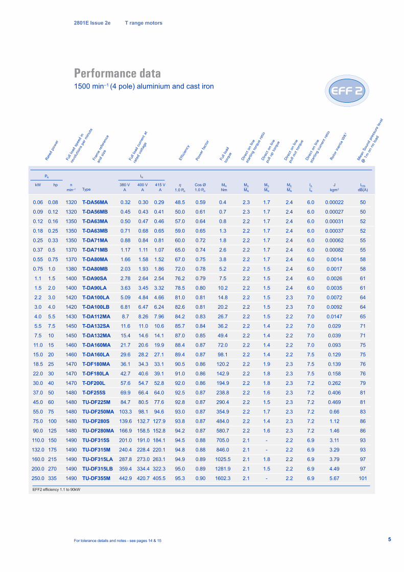
Performance data1500 min–1 (4 pole) aluminium and cast iron
2801E Issue 2e T range motors
For tolerance details and notes - see pages 14 & 15
kW hp
PN
n
min–1
0.06
0.09
0.12
0.18
0.25
0.37
0.55
0.75
1.1
1.5
2.2
3.0
4.0
5.5
7.5
11.0
15.0
18.5
22.0
30.0
37.0
45.0
55.0
75.0
90.0
110.0
132.0
160.0
200.0
250.0
1320
1320
1350
1350
1350
1370
1370
1380
1400
1400
1420
1420
1430
1450
1450
1460
1460
1470
1470
1470
1480
1480
1480
1480
1480
1490
1490
1490
1490
1490
T-DA56MA
T-DA56MB
T-DA63MA
T-DA63MB
T-DA71MA
T-DA71MB
T-DA80MA
T-DA80MB
T-DA90SA
T-DA90LA
T-DA100LA
T-DA100LB
T-DA112MA
T-DA132SA
T-DA132MA
T-DA160MA
T-DA160LA
T-DF180MA
T-DF180LA
T-DF200L
T-DF255S
TU-DF225M
TU-DF250MA
TU-DF280S
TU-DF280MA
TU-DF315S
TU-DF315M
TU-DF315LA
TU-DF315LB
TU-DF355M
0.08
0.12
0.16
0.25
0.33
0.5
0.75
1.0
1.5
2.0
3.0
4.0
5.5
7.5
10
15
20
25
30
40
50
60
75
100
125
150
175
215
270
335
380 V
A
400 V
A
415 V
A
η1.0 PN
MA
MN
IAIN
MK
MN
J
kgm2
IN
0.32
0.45
0.50
0.71
0.88
1.17
1.66
2.03
2.78
3.63
5.09
6.81
8.7
11.6
15.4
21.7
29.6
36.1
42.7
57.6
69.9
84.7
103.3
139.6
166.9
201.0
240.4
287.8
359.4
442.9
0.30
0.43
0.47
0.68
0.84
1.11
1.58
1.93
2.64
3.45
4.84
6.47
8.26
11.0
14.6
20.6
28.2
34.3
40.6
54.7
66.4
80.5
98.1
132.7
158.5
191.0
228.4
273.0
334.4
420.7
0.29
0.41
0.46
0.65
0.81
1.07
1.52
1.86
2.54
3.32
4.66
6.24
7.96
10.6
14.1
19.9
27.1
33.1
39.1
52.8
64.0
77.6
94.6
127.9
152.8
184.1
220.1
263.1
322.3
405.5
48.5
50.0
57.0
59.0
60.0
65.0
67.0
72.0
76.2
78.5
81.0
82.6
84.2
85.7
87.0
88.4
89.4
90.5
91.0
92.0
92.5
92.8
93.0
93.8
94.2
94.5
94.8
94.9
95.0
95.3
2.3
2.3
2.2
2.2
2.2
2.2
2.2
2.2
2.2
2.2
2.2
2.2
2.2
2.2
2.2
2.2
2.2
2.2
2.2
2.2
2.2
2.2
2.2
2.2
2.2
2.1
2.1
2.1
2.1
2.1
6.0
6.0
6.0
6.0
6.0
6.0
6.0
6.0
6.0
6.0
7.0
7.0
7.0
7.0
7.0
7.0
7.5
7.5
7.5
7.2
7.2
7.2
7.2
7.2
7.2
6.9
6.9
6.9
6.9
6.9
2.4
2.4
2.4
2.4
2.4
2.4
2.4
2.4
2.4
2.4
2.3
2.3
2.2
2.2
2.2
2.2
2.2
2.3
2.3
2.3
2.3
2.3
2.3
2.3
2.3
2.2
2.2
2.2
2.2
2.2
0.00022
0.00027
0.00031
0.00037
0.00062
0.00082
0.0014
0.0017
0.0026
0.0035
0.0072
0.0092
0.0147
0.029
0.039
0.093
0.129
0.139
0.158
0.262
0.406
0.469
0.66
1.12
1.46
3.11
3.29
3.79
4.49
5.67
Roto
r ine
rtia
WK
2
Dire
ct o
n lin
e
pull
out t
orqu
eDi
rect
on
line
star
ting
curre
nt ra
tio
Dire
ct o
n lin
e
star
ting
torq
ue ra
tio
Pow
er fa
ctor
Effic
ienc
y
Full
load
cur
rent
at
rate
d vo
ltage
Fram
e re
fere
nce
and
size
Full
load
spe
ed in
revo
lutio
ns p
er m
inut
e
Rate
d po
wer
TypeCos Ø
1.0 PN
0.59
0.61
0.64
0.65
0.72
0.74
0.75
0.78
0.79
0.80
0.81
0.81
0.83
0.84
0.85
0.87
0.87
0.86
0.86
0.86
0.87
0.87
0.87
0.87
0.87
0.88
0.88
0.89
0.89
0.90
0.4
0.7
0.8
1.3
1.8
2.6
3.8
5.2
7.5
10.2
14.8
20.2
26.7
36.2
49.4
72.0
98.1
120.2
142.9
194.9
238.8
290.4
354.9
484.0
580.7
705.0
846.0
1025.5
1281.9
1602.3
Full
load
torq
ue
MN
Nm
MS
MN
1.7
1.7
1.7
1.7
1.7
1.7
1.7
1.5
1.5
1.5
1.5
1.5
1.5
1.4
1.4
1.4
1.4
1.9
1.8
1.8
1.6
1.5
1.7
1.4
1.6
-
-
1.8
1.5
-
Dire
ct o
n lin
e
pull
up to
rque
LPA
dB(A)
50
50
52
52
55
55
58
58
61
61
64
64
65
71
71
75
75
76
76
79
81
81
83
86
86
93
93
97
97
101
Mea
n So
und
pres
sure
leve
l
@ 1
m o
n no
load
EFF2 efficiency 1.1 to 90kW
6
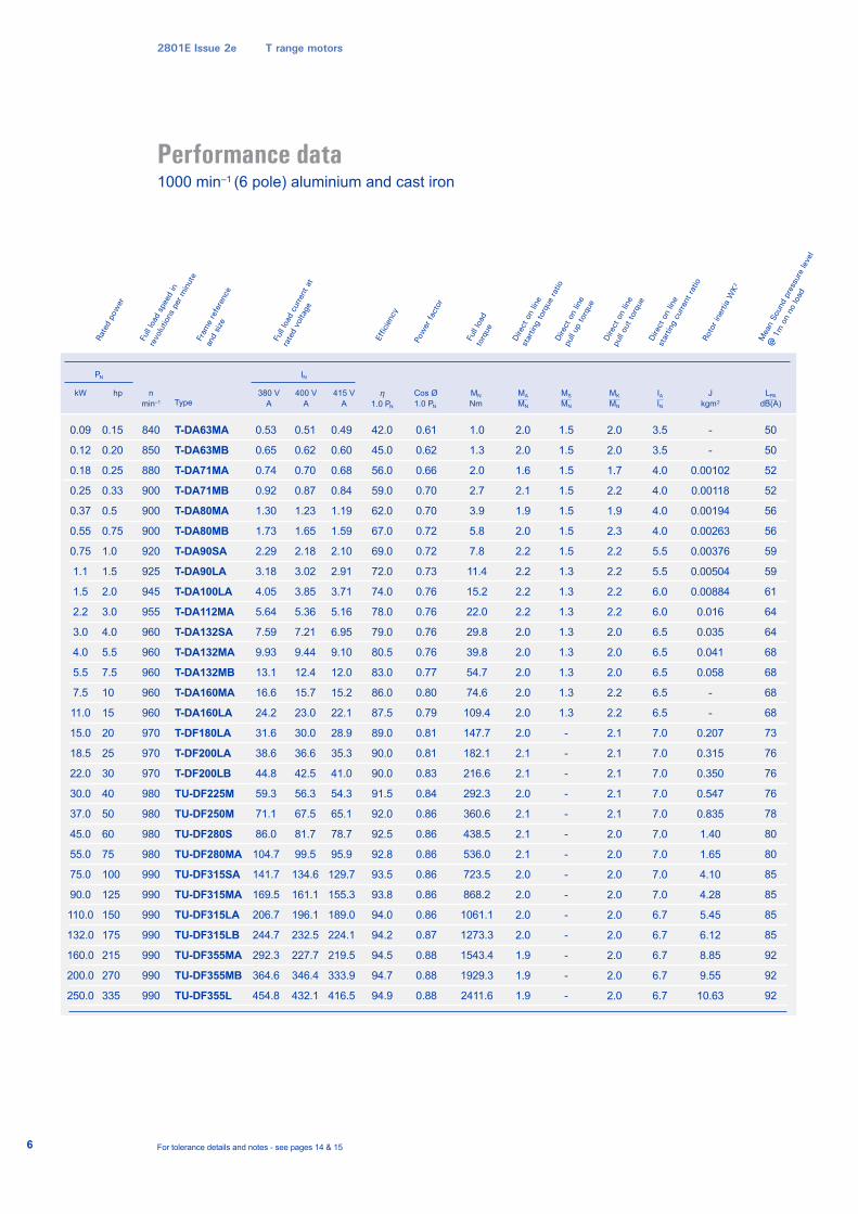
Performance data1000 min–1 (6 pole) aluminium and cast iron
2801E Issue 2e T range motors
For tolerance details and notes - see pages 14 & 15
kW hp
PN
n
min–1
0.09
0.12
0.18
0.25
0.37
0.55
0.75
1.1
1.5
2.2
3.0
4.0
5.5
7.5
11.0
15.0
18.5
22.0
30.0
37.0
45.0
55.0
75.0
90.0
110.0
132.0
160.0
200.0
250.0
840
850
880
900
900
900
920
925
945
955
960
960
960
960
960
970
970
970
980
980
980
980
990
990
990
990
990
990
990
T-DA63MA
T-DA63MB
T-DA71MA
T-DA71MB
T-DA80MA
T-DA80MB
T-DA90SA
T-DA90LA
T-DA100LA
T-DA112MA
T-DA132SA
T-DA132MA
T-DA132MB
T-DA160MA
T-DA160LA
T-DF180LA
T-DF200LA
T-DF200LB
TU-DF225M
TU-DF250M
TU-DF280S
TU-DF280MA
TU-DF315SA
TU-DF315MA
TU-DF315LA
TU-DF315LB
TU-DF355MA
TU-DF355MB
TU-DF355L
0.15
0.20
0.25
0.33
0.5
0.75
1.0
1.5
2.0
3.0
4.0
5.5
7.5
10
15
20
25
30
40
50
60
75
100
125
150
175
215
270
335
380 V
A
400 V
A
415 V
A
η1.0 PN
MA
MN
IAIN
MK
MN
J
kgm2
IN
0.53
0.65
0.74
0.92
1.30
1.73
2.29
3.18
4.05
5.64
7.59
9.93
13.1
16.6
24.2
31.6
38.6
44.8
59.3
71.1
86.0
104.7
141.7
169.5
206.7
244.7
292.3
364.6
454.8
0.51
0.62
0.70
0.87
1.23
1.65
2.18
3.02
3.85
5.36
7.21
9.44
12.4
15.7
23.0
30.0
36.6
42.5
56.3
67.5
81.7
99.5
134.6
161.1
196.1
232.5
227.7
346.4
432.1
0.49
0.60
0.68
0.84
1.19
1.59
2.10
2.91
3.71
5.16
6.95
9.10
12.0
15.2
22.1
28.9
35.3
41.0
54.3
65.1
78.7
95.9
129.7
155.3
189.0
224.1
219.5
333.9
416.5
42.0
45.0
56.0
59.0
62.0
67.0
69.0
72.0
74.0
78.0
79.0
80.5
83.0
86.0
87.5
89.0
90.0
90.0
91.5
92.0
92.5
92.8
93.5
93.8
94.0
94.2
94.5
94.7
94.9
2.0
2.0
1.6
2.1
1.9
2.0
2.2
2.2
2.2
2.2
2.0
2.0
2.0
2.0
2.0
2.0
2.1
2.1
2.0
2.1
2.1
2.1
2.0
2.0
2.0
2.0
1.9
1.9
1.9
3.5
3.5
4.0
4.0
4.0
4.0
5.5
5.5
6.0
6.0
6.5
6.5
6.5
6.5
6.5
7.0
7.0
7.0
7.0
7.0
7.0
7.0
7.0
7.0
6.7
6.7
6.7
6.7
6.7
2.0
2.0
1.7
2.2
1.9
2.3
2.2
2.2
2.2
2.2
2.0
2.0
2.0
2.2
2.2
2.1
2.1
2.1
2.1
2.1
2.0
2.0
2.0
2.0
2.0
2.0
2.0
2.0
2.0
-
-
0.00102
0.00118
0.00194
0.00263
0.00376
0.00504
0.00884
0.016
0.035
0.041
0.058
-
-
0.207
0.315
0.350
0.547
0.835
1.40
1.65
4.10
4.28
5.45
6.12
8.85
9.55
10.63
Roto
r ine
rtia
WK
2
Dire
ct o
n lin
e
pull
out t
orqu
eDi
rect
on
line
star
ting
curre
nt ra
tio
Dire
ct o
n lin
e
star
ting
torq
ue ra
tio
Pow
er fa
ctor
Effic
ienc
y
Full
load
cur
rent
at
rate
d vo
ltage
Fram
e re
fere
nce
and
size
Full
load
spe
ed in
revo
lutio
ns p
er m
inut
e
Rate
d po
wer
TypeCos Ø
1.0 PN
0.61
0.62
0.66
0.70
0.70
0.72
0.72
0.73
0.76
0.76
0.76
0.76
0.77
0.80
0.79
0.81
0.81
0.83
0.84
0.86
0.86
0.86
0.86
0.86
0.86
0.87
0.88
0.88
0.88
1.0
1.3
2.0
2.7
3.9
5.8
7.8
11.4
15.2
22.0
29.8
39.8
54.7
74.6
109.4
147.7
182.1
216.6
292.3
360.6
438.5
536.0
723.5
868.2
1061.1
1273.3
1543.4
1929.3
2411.6
Full
load
torq
ue
MN
Nm
MS
MN
1.5
1.5
1.5
1.5
1.5
1.5
1.5
1.3
1.3
1.3
1.3
1.3
1.3
1.3
1.3
-
-
-
-
-
-
-
-
-
-
-
-
-
-
Dire
ct o
n lin
e
pull
up to
rque
LPA
dB(A)
50
50
52
52
56
56
59
59
61
64
64
68
68
68
68
73
76
76
76
78
80
80
85
85
85
85
92
92
92
Mea
n So
und
pres
sure
leve
l
@ 1
m o
n no
load
7
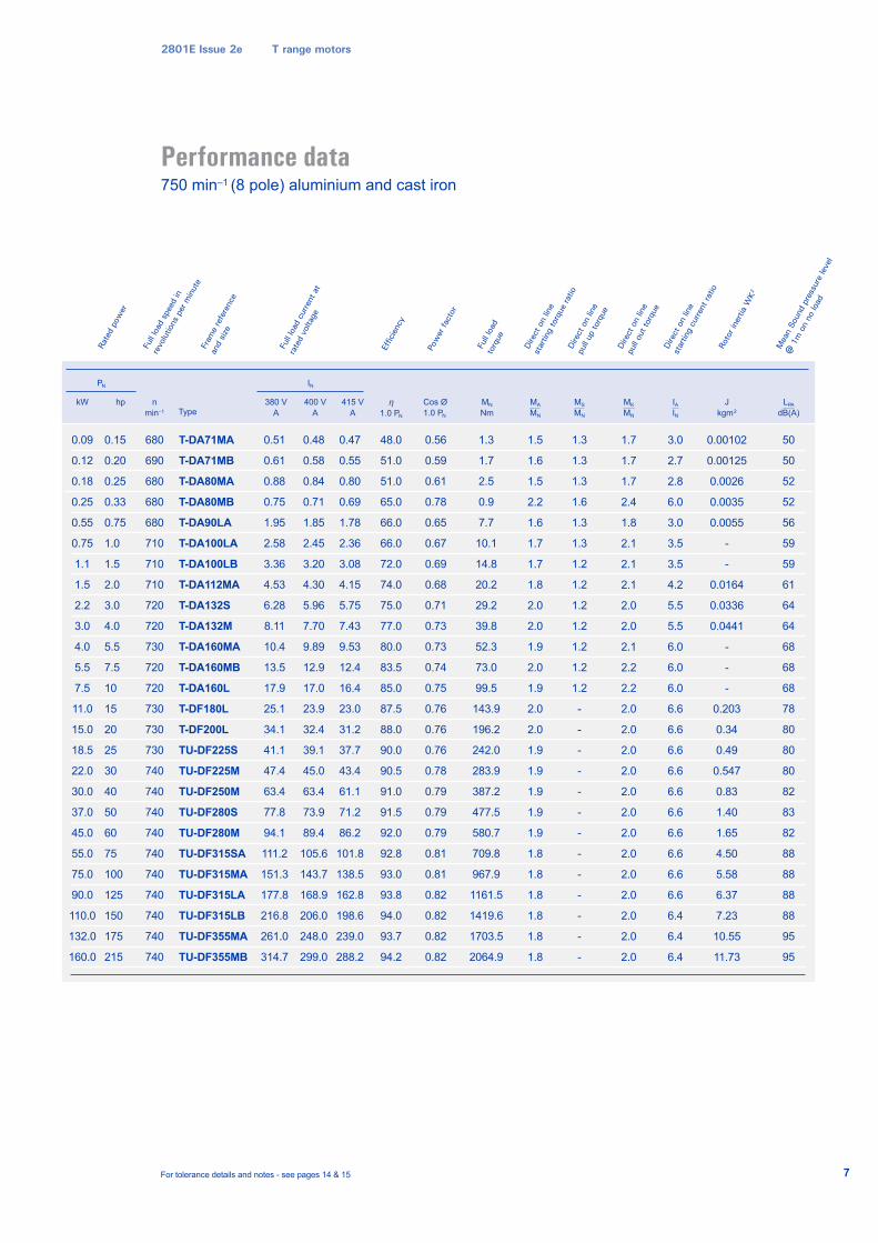
Performance data750 min–1 (8 pole) aluminium and cast iron
2801E Issue 2e T range motors
For tolerance details and notes - see pages 14 & 15
kW hp
PN
n
min–1
0.09
0.12
0.18
0.25
0.55
0.75
1.1
1.5
2.2
3.0
4.0
5.5
7.5
11.0
15.0
18.5
22.0
30.0
37.0
45.0
55.0
75.0
90.0
110.0
132.0
160.0
680
690
680
680
680
710
710
710
720
720
730
720
720
730
730
730
740
740
740
740
740
740
740
740
740
740
T-DA71MA
T-DA71MB
T-DA80MA
T-DA80MB
T-DA90LA
T-DA100LA
T-DA100LB
T-DA112MA
T-DA132S
T-DA132M
T-DA160MA
T-DA160MB
T-DA160L
T-DF180L
T-DF200L
TU-DF225S
TU-DF225M
TU-DF250M
TU-DF280S
TU-DF280M
TU-DF315SA
TU-DF315MA
TU-DF315LA
TU-DF315LB
TU-DF355MA
TU-DF355MB
0.15
0.20
0.25
0.33
0.75
1.0
1.5
2.0
3.0
4.0
5.5
7.5
10
15
20
25
30
40
50
60
75
100
125
150
175
215
380 V
A
400 V
A
415 V
A
η1.0 PN
MA
MN
IAIN
MK
MN
J
kgm2
IN
0.51
0.61
0.88
0.75
1.95
2.58
3.36
4.53
6.28
8.11
10.4
13.5
17.9
25.1
34.1
41.1
47.4
63.4
77.8
94.1
111.2
151.3
177.8
216.8
261.0
314.7
0.48
0.58
0.84
0.71
1.85
2.45
3.20
4.30
5.96
7.70
9.89
12.9
17.0
23.9
32.4
39.1
45.0
63.4
73.9
89.4
105.6
143.7
168.9
206.0
248.0
299.0
0.47
0.55
0.80
0.69
1.78
2.36
3.08
4.15
5.75
7.43
9.53
12.4
16.4
23.0
31.2
37.7
43.4
61.1
71.2
86.2
101.8
138.5
162.8
198.6
239.0
288.2
48.0
51.0
51.0
65.0
66.0
66.0
72.0
74.0
75.0
77.0
80.0
83.5
85.0
87.5
88.0
90.0
90.5
91.0
91.5
92.0
92.8
93.0
93.8
94.0
93.7
94.2
1.5
1.6
1.5
2.2
1.6
1.7
1.7
1.8
2.0
2.0
1.9
2.0
1.9
2.0
2.0
1.9
1.9
1.9
1.9
1.9
1.8
1.8
1.8
1.8
1.8
1.8
3.0
2.7
2.8
6.0
3.0
3.5
3.5
4.2
5.5
5.5
6.0
6.0
6.0
6.6
6.6
6.6
6.6
6.6
6.6
6.6
6.6
6.6
6.6
6.4
6.4
6.4
1.7
1.7
1.7
2.4
1.8
2.1
2.1
2.1
2.0
2.0
2.1
2.2
2.2
2.0
2.0
2.0
2.0
2.0
2.0
2.0
2.0
2.0
2.0
2.0
2.0
2.0
0.00102
0.00125
0.0026
0.0035
0.0055
-
-
0.0164
0.0336
0.0441
-
-
-
0.203
0.34
0.49
0.547
0.83
1.40
1.65
4.50
5.58
6.37
7.23
10.55
11.73
Roto
r ine
rtia
WK
2
Dire
ct o
n lin
e
pull
out t
orqu
eDi
rect
on
line
star
ting
curre
nt ra
tio
Dire
ct o
n lin
e
star
ting
torq
ue ra
tio
Pow
er fa
ctor
Effic
ienc
y
Full
load
cur
rent
at
rate
d vo
ltage
Fram
e re
fere
nce
and
size
Full
load
spe
ed in
revo
lutio
ns p
er m
inut
e
Rate
d po
wer
TypeCos Ø
1.0 PN
0.56
0.59
0.61
0.78
0.65
0.67
0.69
0.68
0.71
0.73
0.73
0.74
0.75
0.76
0.76
0.76
0.78
0.79
0.79
0.79
0.81
0.81
0.82
0.82
0.82
0.82
1.3
1.7
2.5
0.9
7.7
10.1
14.8
20.2
29.2
39.8
52.3
73.0
99.5
143.9
196.2
242.0
283.9
387.2
477.5
580.7
709.8
967.9
1161.5
1419.6
1703.5
2064.9
Full
load
torq
ue
MN
Nm
MS
MN
1.3
1.3
1.3
1.6
1.3
1.3
1.2
1.2
1.2
1.2
1.2
1.2
1.2
-
-
-
-
-
-
-
-
-
-
-
-
-
Dire
ct o
n lin
e
pull
up to
rque
LPA
dB(A)
50
50
52
52
56
59
59
61
64
64
68
68
68
78
80
80
80
82
83
82
88
88
88
88
95
95
Mea
n So
und
pres
sure
leve
l
@ 1
m o
n no
load
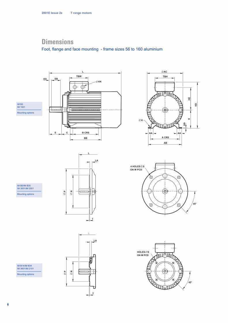
2801E Issue 2e T range motors
DimensionsFoot, flange and face mounting - frame sizes 56 to 160 aluminium
IM B3
IM 1001
Mounting options
IM B14/IM B34
IM 3601/IM 2101
Mounting options
IM B5/IM B35
IM 3001/IM 2001
Mounting options
B CRS
L
EBTBW
E C
BB
KKED
L
LA
P N
T
A CRS
AB
AA
K
HA
HH
E
HD
TBH
AC
AA
4 HOLES S
ON M PCD
45°
L
LA
P N
T
HOLES S
ON M PCD
45°
8
2801E Issue 2e T range motors
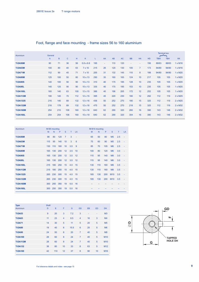
T-DA56M
T-DA63M
T-DA71M
T-DA80M
T-DA90S
T-DA90L
T-DA100L
T-DA112M
T-DA132S
T-DA132M
T-DA160M
T-DA160L
Aluminium
90
100
112
125
140
140
160
190
216
216
254
254
General
A
71
80
90
100
100
125
140
140
140
178
210
254
B
36
40
45
50
56
56
63
70
89
89
108
108
C
56
63
71
80
90
90
100
112
132
132
160
160
H
5.8 x 8.8
7 x 10
7 x 10
10 x 13
10 x 13
10 x 13
12 x 15
12 x 15
12 x 16
12 x 16
12 x 16
15 x 19
K KKL AA AB AC BB HA HD TBW
1 x M16
1 x M16
1 x M20
1 x M20
1 x M20
1 x M20
1 x M20
2 x M25
2 x M25
2 x M32
2 x M32
2 x M32
195
215
255
290
310
335
386
395
436
475
640
640
-
26
31
35
40
40
40
45
50
50
62
62
110
120
132
160
175
175
196
220
252
252
290
290
120
130
145
165
185
185
205
230
270
270
320
320
-
100
110
124
128
153
172
180
180
218
260
304
-
7
8
10
10
10
12
12
15
15
16
16
156
173
188
217
235
235
252
292
325
325
390
390
88/63
94/80
94/80
105
105
105
105
112
112
112
143
143
88/63
94/80
94/80
105
105
105
105
119
119
119
146
146
TBH
Aluminium IM B5 mounting
98
115
130
165
165
165
215
215
265
265
300
300
M
80
95
110
130
130
130
180
180
230
230
250
250
N
120
140
160
200
200
200
250
250
300
300
350
350
P
-
8
9
10
12
12
15
15
15
15
16
16
LA
7
10
10
12
12
12
15
15
15
15
19
19
S
3
3
3.5
3.5
3.5
3.5
4.0
4.0
4.0
4.0
5.0
5.0
T
IM B14 mounting
65
75
85
100
115
115
130
130
165
165
–
–
M
50
60
70
80
95
95
110
110
130
130
–
–
N
80
90
105
120
140
140
160
160
200
200
–
–
P
-
-
-
-
-
-
-
-
-
-
-
-
LA
M5
M5
M6
M6
M8
M6
M8
M8
M10
M10
–
–
S
2.5
2.5
2.5
3.0
3.0
3.0
3.5
3.5
3.5
3.5
–
–
T
Type Shaft
For tolerance details and notes - see page 15
T-DA53
T-DA63
T-DA71
T-DA80
T-DA90
T-DA100
T-DA112M
T-DA132
T-DA160
9
11
14
19
24
28
28
38
42
D
M3
M4
M5
M6
M8
M10
M10
M12
M16
DH
3
4
5
6
8
8
8
10
12
F
20
23
30
40
50
60
60
80
110
E
7.2
8.5
11
15.5
20
24
24
33
37
G
-
16
20
25
40
45
45
63
90
EB
TAPPED
HOLE DH
F
D
GD
G
9
T-DA56M
T-DA63M
T-DA71M
T-DA80M
T-DA90S
T-DA90L
T-DA100L
T-DA112M
T-DA132S
T-DA132M
T-DA160M
T-DA160L
3
4
5
6
7
7
7
8
8
GDAluminium
-
3
5
5
5
5
5
5
10
ED
Foot, flange and face mounting - frame sizes 56 to 160 aluminium
Terminal box}
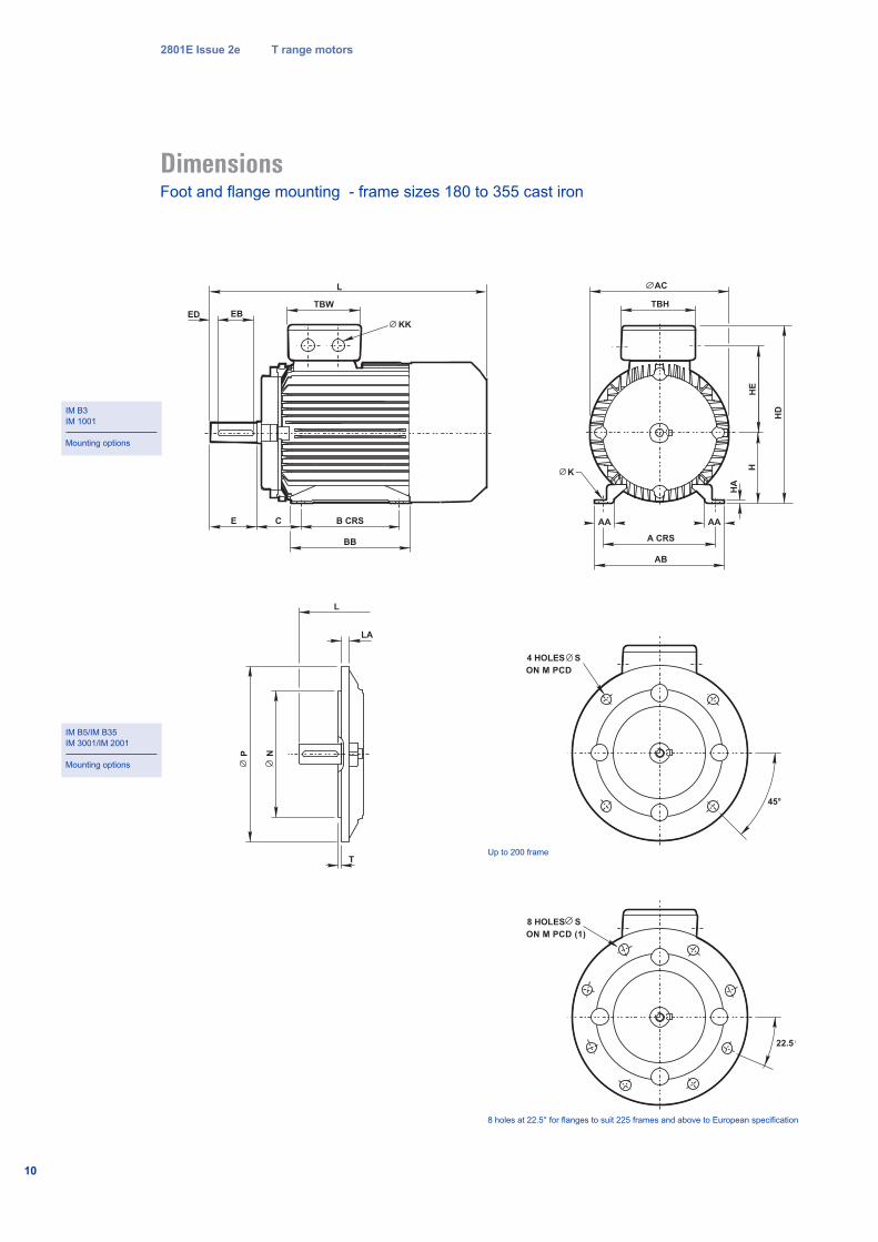
2801E Issue 2e T range motors
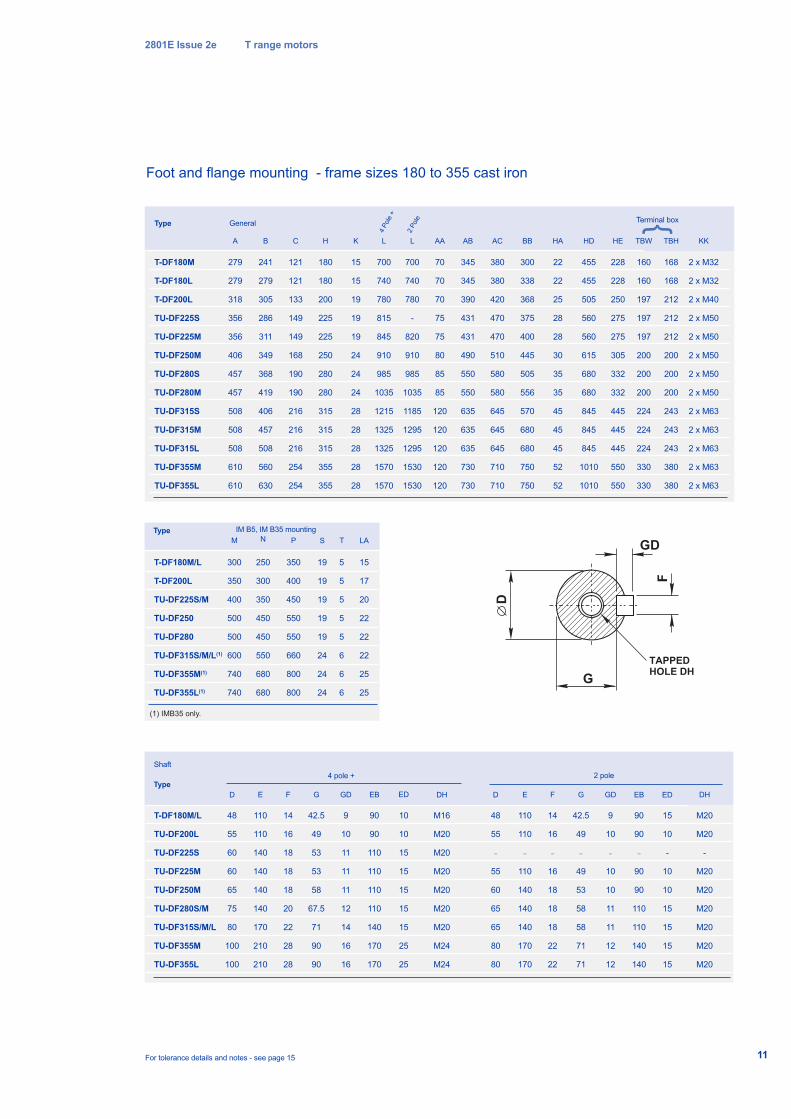
DimensionsFoot and flange mounting - frame sizes 180 to 355 cast iron
IM B3
IM 1001
Mounting options
IM B5/IM B35
IM 3001/IM 2001
Mounting options
B CRS
L
EBTBW
E C
BB
KKED
L
LA
P N
T
A CRS
AB
AA
K
HA
HH
E
HD
TBH
AC
AA
4 HOLES S
ON M PCD
45°
10
8 HOLES S
ON M PCD (1)
22.5°
8 holes at 22.5° for flanges to suit 225 frames and above to European specification
Up to 200 frame
2801E Issue 2e T range motors
For tolerance details and notes - see page 15
TAPPED
HOLE DHF
D
GD
G
T-DF180M
T-DF180L
T-DF200L
TU-DF225S
TU-DF225M
TU-DF250M
TU-DF280S
TU-DF280M
TU-DF315S
TU-DF315M
TU-DF315L
TU-DF355M
TU-DF355L
Type
279
279
318
356
356
406
457
457
508
508
508
610
610
General Terminal box
A
241
279
305
286
311
349
368
419
406
457
508
560
630
B
121
121
133
149
149
168
190
190
216
216
216
254
254
C
180
180
200
225
225
250
280
280
315
315
315
355
355
H
15
15
19
19
19
24
24
24
28
28
28
28
28
K
2 x M32
2 x M32
2 x M40
2 x M50
2 x M50
2 x M50
2 x M50
2 x M50
2 x M63
2 x M63
2 x M63
2 x M63
2 x M63
KK
700
740
780
815
845
910
985
1035
1215
1325
1325
1570
1570
L
70
70
70
75
75
80
85
85
120
120
120
120
120
AA
345
345
390
431
431
490
550
550
635
635
635
730
730
AB
380
380
420
470
470
510
580
580
645
645
645
710
710
AC
300
338
368
375
400
445
505
556
570
680
680
750
750
BB
22
22
25
28
28
30
35
35
45
45
45
52
52
HA
455
455
505
560
560
615
680
680
845
845
845
1010
1010
HD
168
168
212
212
212
200
200
200
243
243
243
380
380
TBH
160
160
197
197
197
200
200
200
224
224
224
330
330
TBW
Type IM B5, IM B35 mounting
300
350
400
500
500
600
740
740
M
250
300
350
450
450
550
680
680
N
350
400
450
550
550
660
800
800
P
15
17
20
22
22
22
25
25
LA
19
19
19
19
19
24
24
24
S
5
5
5
5
5
6
6
6
T
T-DF180M/L
TU-DF200L
TU-DF225S
TU-DF225M
TU-DF250M
TU-DF280S/M
TU-DF315S/M/L
TU-DF355M
TU-DF355L
Type
Shaft
48
55
60
60
65
75
80
100
100
D
M20
M20
-
M20
M20
M20
M20
M20
M20
DH
14
16
18
18
18
20
22
28
28
F
42.5
49
53
53
58
67.5
71
90
90
G
90
90
110
110
110
110
140
170
170
EB
11
48
55
_
55
60
65
65
80
80
D
110
110
_
110
140
140
140
170
170
E
14
16
_
16
18
18
18
22
22
F
42.5
49
_
49
53
58
58
71
71
G
110
110
140
140
140
140
170
210
210
E
90
90
_
90
90
110
110
140
140
EB
9
10
11
11
11
12
14
16
16
GD
9
10
_
10
10
11
11
12
12
GD
10
10
15
15
15
15
15
25
25
ED
15
10
-
10
10
15
15
15
15
ED
Foot and flange mounting - frame sizes 180 to 355 cast iron
(1) IMB35 only.
M16
M20
M20
M20
M20
M20
M20
M24
M24
DH
2 pole4 pole +
HE
228
228
250
275
275
305
332
332
445
445
445
550
550
700
740
780
-
820
910
985
1035
1185
1295
1295
1530
1530
L
4 P
ole
+
2 P
ole
T-DF180M/L
T-DF200L
TU-DF225S/M
TU-DF250
TU-DF280
TU-DF315S/M/L(1)
TU-DF355M(1)
TU-DF355L(1)
}
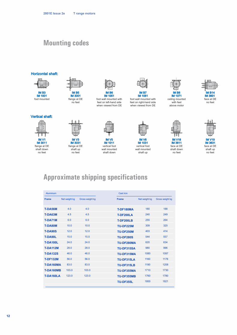
Mounting codes
Frame Net weight kg Gross weight kg
4.0
4.5
6.0
10.0
12.0
15.0
24.0
28.0
46.0
56.0
83.0
103.0
123.0
Cast ironAluminium
Approximate shipping specifications
Horizontal shaft:Horizontal shaft:
Vertical shaft:Vertical shaft:
IM B3IM B3IM 1001IM 1001
foot mounted
IM B5IM B5IM 3001IM 3001
flange at DE
no feet
IM B14IM B14IM 3601 IM 3601 face at DE
no feet
IM B6IM B6IM 1051IM 1051
foot wall mounted with
feet on left-hand side
when viewed from DE
IM B7IM B7IM 1061IM 1061
foot wall mounted with
feet on right-hand side
when viewed from DE
IM B8IM B8IM 1071IM 1071
ceiling mounted
with feet
above motor
IM V1IM V1IM 3011IM 3011
flange at DE
shaft down
no feet
IM V3IM V3IM 3031IM 3031
flange at DE
shaft up
no feet
IM V5IM V5IM 1011IM 1011
vertical foot
wall mounted
shaft down
IM V6IM V6IM 1031IM 1031
vertical foot
wall mounted
shaft up
IM V18IM V18IM 3611IM 3611
face at DE
shaft down
no feet
IM V19IM V19IM 3631IM 3631
face at DE
shaft up
no feet
2801E Issue 2e T range motors
12
T-DA56M
T-DA63M
T-DA71M
T-DA80M
T-DA90S
T-DA90L
T-DA100L
T-DA112M
T-DA132S
T-DF132M
T-DA160MA
T-DA160MB
T-DA160LA
T-DF180MA
T-DF200LA
T-DF200LB
TU-DF225M
TU-DF250M
TU-DF280S
TU-DF280MA
TU-DF315SA
TU-DF315MA
TU-DF315LA
TU-DF315LB
TU-DF355MA
TU-DF355MB
TU-DF355L
4.0
4.5
6.0
10.0
12.0
15.0
24.0
28.0
46.0
56.0
83.0
103.0
123.0
Net weight kg Gross weight kg
180
240
255
309
403
544
620
980
1080
1160
1190
1710
1760
1800
188
249
264
320
414
557
634
996
1097
1178
1208
1730
1780
1821
Frame
2801E Issue 2e T range motors
13
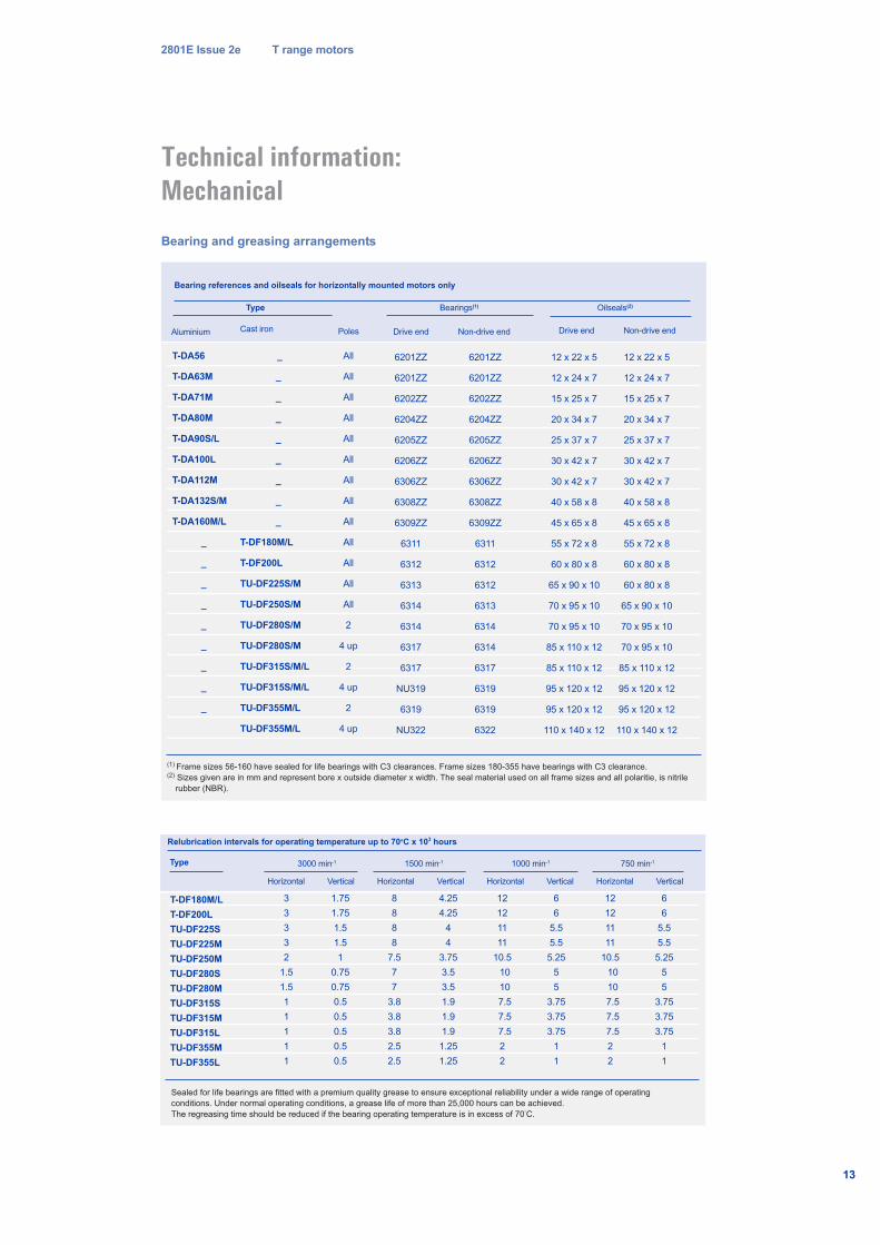
Technical information:Mechanical
_
_
_
_
_
_
_
_
_
T-DF180M/L
T-DF200L
TU-DF225S/M
TU-DF250S/M
TU-DF280S/M
TU-DF280S/M
TU-DF315S/M/L
TU-DF315S/M/L
TU-DF355M/L
TU-DF355M/L
Bearing references and oilseals for horizontally mounted motors only
All
All
All
All
All
All
All
All
All
All
All
All
All
2
4 up
2
4 up
2
4 up
(1) Frame sizes 56-160 have sealed for life bearings with C3 clearances. Frame sizes 180-355 have bearings with C3 clearance.(2) Sizes given are in mm and represent bore x outside diameter x width. The seal material used on all frame sizes and all polaritie, is nitrile
rubber (NBR).
Type
T-DA56
T-DA63M
T-DA71M
T-DA80M
T-DA90S/L
T-DA100L
T-DA112M
T-DA132S/M
T-DA160M/L
_
_
_
_
_
_
_
_
_
Cast ironAluminium Poles
Bearings(1) Oilseals(2)
T-DF180M/L
T-DF200L
TU-DF225S
TU-DF225M
TU-DF250M
TU-DF280S
TU-DF280M
TU-DF315S
TU-DF315M
TU-DF315L
TU-DF355M
TU-DF355L
Relubrication intervals for operating temperature up to 70oC x 103 hours
Horizontal Vertical Horizontal Vertical Horizontal Vertical Horizontal Vertical
3
3
3
3
2
1.5
1.5
1
1
1
1
1
1.75
1.75
1.5
1.5
1
0.75
0.75
0.5
0.5
0.5
0.5
0.5
8
8
8
8
7.5
7
7
3.8
3.8
3.8
2.5
2.5
4.25
4.25
4
4
3.75
3.5
3.5
1.9
1.9
1.9
1.25
1.25
12
12
11
11
10.5
10
10
7.5
7.5
7.5
2
2
6
6
5.5
5.5
5.25
5
5
3.75
3.75
3.75
1
1
12
12
11
11
10.5
10
10
7.5
7.5
7.5
2
2
6
6
5.5
5.5
5.25
5
5
3.75
3.75
3.75
1
1
Sealed for life bearings are fitted with a premium quality grease to ensure exceptional reliability under a wide range of operating
conditions. Under normal operating conditions, a grease life of more than 25,000 hours can be achieved.
The regreasing time should be reduced if the bearing operating temperature is in excess of 70°C.
Type 3000 min-1 1500 min-1 1000 min-1 750 min-1
Bearing and greasing arrangements
6201ZZ
6201ZZ
6202ZZ
6204ZZ
6205ZZ
6206ZZ
6306ZZ
6308ZZ
6309ZZ
6311
6312
6313
6314
6314
6317
6317
NU319
6319
NU322
12 x 22 x 5
12 x 24 x 7
15 x 25 x 7
20 x 34 x 7
25 x 37 x 7
30 x 42 x 7
30 x 42 x 7
40 x 58 x 8
45 x 65 x 8
55 x 72 x 8
60 x 80 x 8
65 x 90 x 10
70 x 95 x 10
70 x 95 x 10
85 x 110 x 12
85 x 110 x 12
95 x 120 x 12
95 x 120 x 12
110 x 140 x 12
6201ZZ
6201ZZ
6202ZZ
6204ZZ
6205ZZ
6206ZZ
6306ZZ
6308ZZ
6309ZZ
6311
6312
6312
6313
6314
6314
6317
6319
6319
6322
Drive end Non-drive end Drive end Non-drive end
12 x 22 x 5
12 x 24 x 7
15 x 25 x 7
20 x 34 x 7
25 x 37 x 7
30 x 42 x 7
30 x 42 x 7
40 x 58 x 8
45 x 65 x 8
55 x 72 x 8
60 x 80 x 8
60 x 80 x 8
65 x 90 x 10
70 x 95 x 10
70 x 95 x 10
85 x 110 x 12
95 x 120 x 12
95 x 120 x 12
110 x 140 x 12
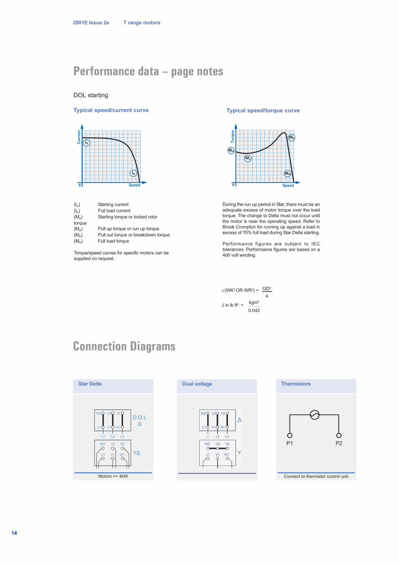
Performance data – page notes
2801E Issue 2e T range motors
14
DOL starting
Typical speed/current curve Typical speed/torque curve
(IA) Starting current
(IN) Full load current
(MA) Starting torque or locked rotor
torque
(MS) Pull up torque or run up torque
(MK) Pull out torque or breakdown torque
(MN) Full load torque
Torque/speed curves for specific motors can be
supplied on request.
J (WK2 OR WR2) =
J in lb ft2 =
GD2
4
kgm2
0.042
During the run up period in Star, there must be an
adequate excess of motor torque over the load
torque. The change to Delta must not occur until
the motor is near the operating speed. Refer to
Brook Crompton for running up against a load in
excess of 70% full load during Star Delta starting.
Performance figures are subject to IEC
tolerances. Performance figures are based on a
400 volt winding.
Connection Diagrams
W2
D.O.L
∆
Y∆
U2 V2
W2 U2 V2
U1 V1 W1
L1 L2 L3
U1 V1 W1
W2 U2 V2
W2 U2 V2
U1 V1 W1
L1 L2 L3
U1 V1 W1
∆
Y
Star Delta Dual voltage
Motors => 4kW
Thermistors
P1 P2
Connect to thermistor control unit.
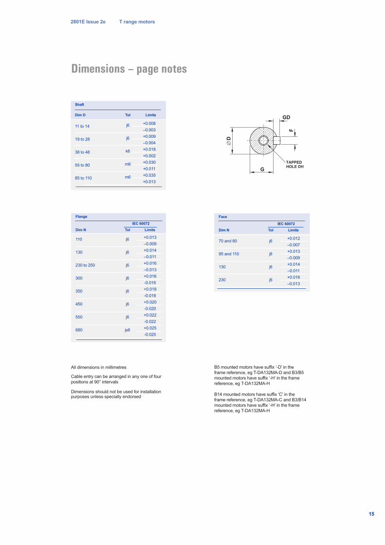
Dimensions – page notes
110
130
230 to 250
300
350
450
550
680
Flange
j6
j6
j6
j6
j6
j6
j6
js6
Dim N
+0.013
–0.009
+0.014
–0.011
+0.016
–0.013
+0.016
-0.016
+0.018
-0.018
+0.020
-0.020
+0.022
-0.022
+0.025
-0.025
Tol Limits
70 and 80
95 and 110
130
230
Face
j6
j6
j6
j6
Dim N
+0.012
–0.007
+0.013
–0.009
+0.014
–0.011
+0.016
–0.013
Tol Limits
TAPPED
HOLE DH
F
D
GD
G
All dimensions in millimetres
Cable entry can be arranged in any one of four
positions at 90° intervals
Dimensions should not be used for installationpurposes unless specially endorsed
11 to 14
19 to 28
38 to 48
55 to 80
85 to 110
Shaft
j6
j6
k6
m6
m6
Dim D
+0.008
–0.003
+0.009
–0.004
+0.018
+0.002
+0.030
+0.011
+0.035
+0.013
Tol Limits
IEC 60072
2801E Issue 2e T range motors
15
B5 mounted motors have suffix ‘-D’ in the
frame reference, eg T-DA132MA-D and B3/B5
mounted motors have suffix ‘-H’ in the frame
reference, eg T-DA132MA-H
B14 mounted motors have suffix ‘C’ in the
frame reference, eg T-DA132MA-C and B3/B14
mounted motors have suffix ‘-H’ in the frame
reference, eg T-DA132MA-H
IEC 60072

Brook CromptonSt Thomas’ Road HuddersfieldWest Yorkshire HD1 3LJ UKTel: +44 (0) 1484 557200Fax: +44 (0) 1484 557201E-mail: [email protected]: www.brookcrompton.com
Printed in England
dh0108/D/A/04/08 2801E Issue 2 (T MkIII)
© Copyright 2008. Brook Crompton. All rights reserved.
R o t a t i n g E l e c t r i c a l M a c h i n e s
Every care has been taken to ensure the accuracy of the
information contained in this publication, but, due to a policy of
continuous development and improvement the right is reserved
to supply products which may differ slightly from those
illustrated and described in this publication


![2970-0-05-0050_0_1[1] HAZID procedure](https://img.pdfslide.us/doc/110x75/577ca80c1a28abea748cac67/2970-0-05-0050011-hazid-procedure.jpg)