Embed Size (px)
Citation preview
Technical Note – TN 019: 20182018 S
uper
sede
d by
T M
U M
D 2
1001
ST
v1.0
, 19/
07/2
019
Technical Note – TN 019: 2018
Subject: Clarification to T MU TE 21001 ST Equipment Rooms and Cubicles, v1.0
Issue date: 14 August 2018
Effective date: 14 August 2018
For queries regarding this document [email protected]
www.transport.nsw.gov.au
This technical note has been issued by the Asset Standards Authority (ASA) as an update to
T MU TE 21001 ST Equipment Rooms and Cubicles, version 1.0 to clarify the minimum
requirements for rack frame dimensions, access clearances and egress pathways, and the
opening direction of external doors.
This following sections relating to provisioning of walk-in and shallow rooms are modified:
• Section 9.1.1 Racks and rails
• Section 9.1.2 Clearances and pathways
1. Section 9.1.1 Racks and rails Replace the contents in its entirety with the following:
Operational equipment shall be mounted in racks or on rails in accordance with the requirements
stated in T MU TE 81001 ST Telecommunication Equipment – Physical Interfaces and
Environmental Conditions.
Racks shall be used to mount operational equipment in equipment rooms.
Racks or rails shall be used to mount operational equipment in cubicles.
In walk-in and shallow rooms, the minimum rack frame dimensions shall be 600 mm wide and
600 mm deep and provide 42 RU.
© State of NSW through Transport for NSW 2018 Page 1 of 2
Technical Note – TN 019: 20182018 S
uper
sede
d by
T M
U M
D 2
1001
ST
v1.0
, 19/
07/2
019
2. Section 9.1.2 Clearances and pathways Replace the contents in its entirety with the following:
A minimum access clearance of at least 1 m shall be maintained on the front and back of racks,
where access is required for operations or maintenance.
A minimum access clearance shall be maintained on the front, back, or both front and back of
racks, where access is required for the safe installation and removal of equipment and racks. The
minimum access clearance shall be the greater of 1 m or the maximum rack frame depth with an
additional clearance of 0.3 m.
In walk-in rooms, an egress pathway with an unobstructed width of 1 m shall be provided.
Note: Additional clearances may apply in relation to switchboards. Refer to
AS/NZS 3000.
In walk-in rooms, an external door shall open inwards if both of the following conditions are met:
• an outwards opening door is not required by statutory instrument
• an outwards opening door would open onto a customer use area
Note: Statutory instruments, such as the NCC and AS/NZS 3000 may require a door to
open outwards to facilitate egress in an emergency.
Otherwise, in walk-in rooms, an external door shall open outwards.
Signage and floor markings shall warn staff and customers of hazards associated with the
direction of opening of external doors.
For cubicles, the concrete pad shall include a clearance of 1 m on all sides.
Authorisation:
Technical content prepared by
Checked and approved by
Interdisciplinary coordination checked by
Authorised for release
Signature
Date
Name James Piper Trevor Payne Peter McGregor Jagath Peiris
Position Principal Engineer (Rail Systems)
Lead Engineer Telecommunications
A/Chief Engineer Director Network Standards and Services
© State of NSW through Transport for NSW 2018 Page 2 of 2
Technical Note - TN 082: 2016
© State of NSW through Transport for NSW Page 1 of 1
For queries regarding this document
[email protected] www.asa.transport.nsw.gov.au
Technical Note - TN 082: 2016 Issued date: 21 December 2016
Subject: Revised reference to risk criteria This technical note has been issued by the Asset Standards Authority (ASA) to notify the
following.
• The risk criteria to be used by the Authorised Engineering Organisations (AEOs) providing
engineering services to TfNSW are contained in T MU MD 20002 ST Risk Criteria for
Organisations Providing Engineering Services, version 1.0.
• 30-ST-164 TfNSW Enterprise Risk Management (TERM) Standard provides the risk criteria
to be used by TfNSW.
• All references to the TERM standard in this document, where applicable to AEOs, shall read
as T MU MD 20002 ST.
Authorisation:
Technical content prepared by
Checked and approved by
Interdisciplinary coordination checked by
Authorised for release
Signature
Date
Name Richard Adams Andy Tankard Andy Tankard Graham Bradshaw
Position Manager Safety and Risk Assurance
Principal Manager SQER
Principal Manager SQER
Director Network Standards and Services
Sup
erse
ded
by T
MU
MD
210
01 S
T v1
.0, 1
9/07
/201
9

Equipment Rooms and Cubicles
T MU TE 21001 ST
Standard
Version 1.0
Issued date: 21 September 2015
Important Warning This document is one of a set of standards developed solely and specifically for use on Transport Assets (as defined in the Asset Standards Authority Charter). It is not suitable for any other purpose. You must not use or adapt it or rely upon it in any way unless you are authorised in writing to do so by a relevant NSW Government agency. If this document forms part of a contract with, or is a condition of approval by a NSW Government agency, use of the document is subject to the terms of the contract or approval. This document is uncontrolled when printed or downloaded. Users should exercise their own skill and care in the use of the document. This document may not be current. Current standards may be accessed from the Asset Standards Authority website at www.asa.transport.nsw.gov.au. © State of NSW through Transport for NSW S
uper
sede
d by
T M
U M
D 2
1001
ST
v1.0
, 19/
07/2
019
T MU TE 21001 ST Equipment Rooms and Cubicles
Version 1.0 Issued date: 21 September 2015
Standard governance
Owner: Lead Telecommunications Engineer, Asset Standards Authority
Authoriser: Chief Engineer Rail, Asset Standards Authority
Approver Executive Director, Asset Standards Authority on behalf of the ASA Configuration Control Board
Document history
Version Summary of Changes
1.0 First issue.
For queries regarding this document, please email the ASA at [email protected] or visit www.asa.transport.nsw.gov.au
© State of NSW through Transport for NSW S
uper
sede
d by
T M
U M
D 2
1001
ST
v1.0
, 19/
07/2
019
T MU TE 21001 ST Equipment Rooms and Cubicles
Version 1.0 Issued date: 21 September 2015
Preface The Asset Standards Authority (ASA) is an independent unit within Transport for NSW (TfNSW)
and is the network design and standards authority for defined NSW transport assets.
The ASA is responsible for developing engineering governance frameworks to support industry
delivery in the assurance of design, safety, integrity, construction, and commissioning of
transport assets for the whole asset life cycle. In order to achieve this, the ASA effectively
discharges obligations as the authority for various technical, process, and planning matters
across the asset life cycle.
The ASA collaborates with industry using stakeholder engagement activities to assist in
achieving its mission. These activities help align the ASA to broader government expectations
of making it clearer, simpler, and more attractive to do business within the NSW transport
industry, allowing the supply chain to deliver safe, efficient, and competent transport services.
The ASA develops, maintains, controls, and publishes a suite of standards and other
documentation for transport assets of TfNSW. Further, the ASA ensures that these standards
are performance-based to create opportunities for innovation and improve access to a broader
competitive supply chain.
This document provides a standard for the construction, fit-out, safety and environmental
sustainability of equipment rooms and cubicles that contain operational telecommunications
equipment or technology.
This standard supersedes T HR TE 21001 ST Telecommunications Equipment Rooms.
This standard is a first issue.
© State of NSW through Transport for NSW Page 3 of 25 S
uper
sede
d by
T M
U M
D 2
1001
ST
v1.0
, 19/
07/2
019
T MU TE 21001 ST Equipment Rooms and Cubicles
Version 1.0 Issued date: 21 September 2015
Table of contents 1. Introduction .............................................................................................................................................. 5
2. Purpose .................................................................................................................................................... 5 2.1. Scope ..................................................................................................................................................... 5 2.2. Application ............................................................................................................................................. 5
3. Reference documents ............................................................................................................................. 6
4. Terms and definitions ............................................................................................................................. 8
5. Risk classification of equipment rooms and cubicles....................................................................... 11
6. General requirements ........................................................................................................................... 11 6.1. Construction requirements ................................................................................................................... 11 6.2. Fit-out requirements ............................................................................................................................. 12 6.3. Safety requirements ............................................................................................................................. 13 6.4. Environmental sustainability requirements .......................................................................................... 13
7. Site selection .......................................................................................................................................... 13 7.1. Earth potential rise zone ...................................................................................................................... 13 7.2. Catch points ......................................................................................................................................... 13 7.3. Flood levels .......................................................................................................................................... 14 7.4. Access ................................................................................................................................................. 14
8. Sizing requirements .............................................................................................................................. 14 8.1. Walk-in rooms ...................................................................................................................................... 14 8.2. Shallow rooms ..................................................................................................................................... 16
9. Provisioning ........................................................................................................................................... 16 9.1. Layout .................................................................................................................................................. 17 9.2. Temperature and humidity limits.......................................................................................................... 17 9.3. Heating, ventilation and air conditioning .............................................................................................. 18 9.4. Power ................................................................................................................................................... 19 9.5. Earthing and surge suppression .......................................................................................................... 21 9.6. Electrostatic discharge ......................................................................................................................... 21 9.7. Noise control ........................................................................................................................................ 21 9.8. Physical security .................................................................................................................................. 22
10. Intra-building pathways ........................................................................................................................ 23 10.1. Access flooring ................................................................................................................................ 23 10.2. Cable trays and wireways ................................................................................................................ 23
11. Intra-building backbone pathways ...................................................................................................... 23
12. Inter-building backbone pathways ...................................................................................................... 24 12.1. Trenches and conduits .................................................................................................................... 24 12.2. Pits ................................................................................................................................................... 25 12.3. Lead-in cable ................................................................................................................................... 25
13. Schedule ................................................................................................................................................. 25
© State of NSW through Transport for NSW Page 4 of 25 S
uper
sede
d by
T M
U M
D 2
1001
ST
v1.0
, 19/
07/2
019
T MU TE 21001 ST Equipment Rooms and Cubicles
Version 1.0 Issued date: 21 September 2015
1. Introduction Equipment rooms and cubicles are required to house the operational telecommunications or
technology that supports freight and passenger transport services.
This standard has been revised and restructured from T HR TE 21001 ST Telecommunications
Equipment Rooms, to improve the alignment and readability of the document in accordance
with AS/NZS 3084:2003 Telecommunications installations – Telecommunications pathways and
spaces for commercial buildings.
2. Purpose This document specifies the requirements for the construction, fit-out, safety and environmental
sustainability of equipment rooms and cubicles that contain operational telecommunications
equipment or technology.
2.1. Scope The scope of this document includes requirements for the following:
• construction, fit-out, safety and environmental sustainability
• site selection
• sizing
• provisioning
• intra-building backbone pathways
• inter-building backbone pathways
2.2. Application This standard applies to any space that contains operational telecommunications equipment or
technology for heavy rail, light rail and rapid transit.
This standard applies to new and altered assets and capital maintenance.
This standard does not apply to recurrent maintenance.
For new equipment rooms and cubicles, full compliance is required. Otherwise, compliance is
required to the applicable sections for the affected assets.
This standard does not apply to contracts and tenders released before the publication of this
document.
The minimum mandatory requirements in this standard may not be sufficient for housing
safety-related equipment.
© State of NSW through Transport for NSW Page 5 of 25 S
uper
sede
d by
T M
U M
D 2
1001
ST
v1.0
, 19/
07/2
019
T MU TE 21001 ST Equipment Rooms and Cubicles
Version 1.0 Issued date: 21 September 2015
T HR TE 21003 ST Telecommunications for Traction Substations and Section Huts contains
additional requirements for telecommunication facilities within high voltage locations.
This standard should be read in conjunction with AS/NZS 3084:2003.
3. Reference documents The following documents are cited in the text. For dated references, only the cited edition
applies. For undated references, the latest edition of the referenced document applies.
International standards
EN 50125-3 Railway applications – Environmental conditions for equipment – Part 3: Equipment
for signalling and telecommunications
IEC 60309-1 Plugs, socket-outlets and couplers for industrial purposes - Part 1: General
requirements
IEC 61340-5-1 Electrostatics – Part 5-1: Protection of electronic devices from electrostatic
phenomena – General requirements
IEC 62262 Degrees of protection provided by enclosures for electrical equipment against
external mechanical impacts (IK code)
IEEE 485 Recommended Practice for Sizing Lead-Acid Batteries for Stationary Applications
Australian standards
AS/NZS 1269.2 Occupational noise management - Noise control management
AS 2201.1:2007 Intruder alarm systems - Client's premises - Design, installation,
commissioning and maintenance
AS/NZS 3000 Electrical installations (known as the Australian/New Zealand Wiring Rules)
AS/NZS 3010 Electrical installations – Generating sets
AS/NZS 3084:2003 Telecommunications installations – Telecommunications pathways and
spaces for commercial buildings
AS/NZS 3112 Approval and test specification - Plugs and socket-outlets
AS 4154 General access floors (elevated floors)
AS 60529 Degrees of protection provided by enclosures (IP Code)
AS/CA S008 Requirements for customer cabling products
AS/CA S009 Installation requirements for customer cabling (Wiring Rules)
© State of NSW through Transport for NSW Page 6 of 25 S
uper
sede
d by
T M
U M
D 2
1001
ST
v1.0
, 19/
07/2
019
T MU TE 21001 ST Equipment Rooms and Cubicles
Version 1.0 Issued date: 21 September 2015
Transport for NSW standards
ESC 250 Turnouts and Special Trackwork
SPM 0123 Reinforced Pre-Cast Concrete Cable Pits
T MU AM 01001 ST Life Cycle Costing
T MU AM 04001 PL TfNSW Configuration Management Plan
T HR TE 01001 ST Communication Outdoor Cabling
T HR TE 21002 ST Communications Earthing and Surge Suppression
T HR TE 21003 ST Telecommunications for Traction Substations and Section Huts
T MU TE 61003 ST Public Address Systems
T HR TE 81001 ST Telecommunication Equipment – Physical Interfaces and Environmental
Conditions
T HR TE 81002 ST Telecommunication Equipment – Network Management
30-ST-164 TfNSW Enterprise Risk Management (TERM) Standard
Legislation
Work Health and Safety Act 2011
Other reference documents
NSW Government Resource Efficiency Policy
NSW Code of Practice – Safe Design of Structures
NSW Code of Practice – Hazardous Manual Tasks
NSW Code of Practice – Managing the Work Environment and Facilities
NSW Code of Practice – Managing Noise and Preventing Hearing Loss at Work
NSW Code of Practice – Managing the Risk of Falls at Workplaces
Australian Government Physical security management guidelines - Security zones and risk
mitigation controls
Australian Government Physical security management guidelines - Physical security of ICT
equipment, systems and facilities
Australian Government Physical security management guidelines – Business impact levels
Rail Industry Safety and Standards Board website glossary
National Construction Code Building Code of Australia
© State of NSW through Transport for NSW Page 7 of 25 S
uper
sede
d by
T M
U M
D 2
1001
ST
v1.0
, 19/
07/2
019
T MU TE 21001 ST Equipment Rooms and Cubicles
Version 1.0 Issued date: 21 September 2015
4. Terms and definitions The following terms and definitions apply in this document:
ac alternating current
ancillary equipment used to support operational equipment such as test equipment and
maintenance laptops
AEO Authorised Engineering Organisation
BCA Building Code of Australia
building (as defined in EN 50125-3) permanent construction provided with main services (e.g.
water, electricity, gas,...) designed to protect equipment against the action of environmental
conditions. A building may or may not be provided with climatic control
capital maintenance also referred to as renewals, is the refurbishment or replacement of an
existing asset, that has reached the end of its useful life, with a new asset capable of providing
the current or agreed alternative level of service as the existing asset. Capital maintenance is
funded from the CAPEX budget.
C.C. (as defined in clause 3.4 of EN 50125-3) with climatic control
CCTV closed-circuit television
configuration item an entity within a configuration that satisfies an end use function
container (as defined in EN 50125-3) shelters/containers are normally provided when a larger
volume of equipment is to be co-located at a single point or temperature/humidity sensitive
equipment is to be installed.
Shelters/containers normally have double walls with insulation material (or an air gap) between
them. Shelters/containers also normally have limited facilities for personnel.
Shelters/containers may also be provided with temperature control, especially where
temperature sensitive apparatus is installed.
Where shelters/containers are fitted with climatic control (temperature and humidity control),
they shall be treated as buildings with climatic control (buildings C.C.).
cubicle (as defined in EN 50125-3) housing for apparatus which normally is used to co-locate
various parts of the signalling or telecommunications system equipment, on occasion from
different suppliers. It may contain various equipment housings installed within the cubicle and
offers further environmental protection.
A cubicle is normally only used to install apparatus and is in general not sufficiently large to
afford protection from weather to staff working on the apparatus.
No climatic or temperature control is provided on cubicles but ventilation or occasionally fan
assisted ventilation is required. © State of NSW through Transport for NSW Page 8 of 25 S
uper
sede
d by
T M
U M
D 2
1001
ST
v1.0
, 19/
07/2
019
T MU TE 21001 ST Equipment Rooms and Cubicles
Version 1.0 Issued date: 21 September 2015
Large housings which allow access to personnel but do not have the thermal properties of
shelters, should be treated as cubicles.
danger zone (as defined in the Rail Industry Safety and Standards Board website glossary)
everywhere within 3m horizontally from the nearest rail and any distance above or below this
3m, unless a safe place exists or has been created
dc direct current
EPR earth potential rise
EPR hazard zone a zone where the EPR may exceed 430 V ac under power system fault
conditions
high voltage location RailCorp high voltage locations including traction substations, section
huts and switching substations
HVAC heating, ventilation and air conditioning
ICT information and communications technology
IP code (as defined in AS 60529) coding system to indicate the degrees of protection provided
by an enclosure against access to hazardous parts, ingress of solid foreign objects, ingress of
water and to give additional information in connection with such protection
IK code (as defined in IEC 62262) coding system to indicate the degree of protection provided
by an enclosure against harmful external mechanical impacts
NABERS national Australian built environment rating system
N.C.C. (as defined in clause 4.3 of EN 50125-3) without climatic control
new and altered assets the changes made to the rail network, other than those as a result of
maintenance activities, including decommissioning and removal of assets from the rail network.
Maintenance activities are considered those made by Authorised Engineering Organisations
(AEOs) with authorisation for maintenance activities and conducted under that authorisation
scope.
N.T.C. (as defined in clause 4.3 of EN 50125-3) without temperature control
operational technology hardware or software that monitor or control assets that support freight
or passenger transport services
operational equipment operational telecommunications equipment or technology
operational associated with the delivery of freight or passenger transport services
rail corridor (as defined in the Rail Industry Safety and Standards Board website glossary) the
land on which a railway is built; comprising all property between property fences, or from the
nearest rail in each direction for the distance specified by the Rail Infrastructure Manager.
© State of NSW through Transport for NSW Page 9 of 25 S
uper
sede
d by
T M
U M
D 2
1001
ST
v1.0
, 19/
07/2
019
T MU TE 21001 ST Equipment Rooms and Cubicles
Version 1.0 Issued date: 21 September 2015
recurrent maintenance also referred to as routine maintenance, is the regular ongoing
day-to-day work that includes the immediate prevention and correction of failures/defects in
assets to ensure the assets are in a safe and operational state. Recurrent maintenance is
funded from the OPEX budget.
room space within a shelter, container or building (as shelter, container and building are
defined in EN 50125-3)
RU rack unit = 44.45 mm
safe place (as defined in the Rail Industry Safety and Standards Board website glossary)
1. A place where workers and equipment cannot be struck by rail traffic.
2. A safe place is a place where no track worksite protection is provided and is either:
• a properly constructed refuge to an approved design;
• behind the safety line on a platform;
• a place where a structure or physical barrier has been erected to provide protection but
includes subways and overhead bridges;
• a place that is not on or near the track.
shallow room space that does not provide rear access to rack-mounted equipment
shelter (as defined in EN 50125-3) shelters/containers are normally provided when a larger
volume of equipment is to be co-located at a single point or temperature/humidity sensitive
equipment is to be installed.
Shelters/containers normally have double walls with insulation material (or an air gap) between
them. Shelters/containers also normally have limited facilities for personnel.
Shelters/containers may also be provided with temperature control, especially where
temperature sensitive apparatus is installed.
Where shelters/containers are fitted with climatic control (temperature and humidity control),
they shall be treated as buildings with climatic control (buildings C.C.)
space (as defined in AS/NZS 3084:2003) area used for housing the installation and termination
of telecommunications equipment and cabling
TERM TfNSW Enterprise Risk Management
T.C. (as defined in EN 50125-3) with temperature control
UNI user network interface
UPS uninterruptible power supply
© State of NSW through Transport for NSW Page 10 of 25 S
uper
sede
d by
T M
U M
D 2
1001
ST
v1.0
, 19/
07/2
019
T MU TE 21001 ST Equipment Rooms and Cubicles
Version 1.0 Issued date: 21 September 2015
5. Risk classification of equipment rooms and cubicles For applying this standard, all risks shall be assessed using the risk matrix defined in 30-ST-164
TfNSW Enterprise Risk Management (TERM) Standard.
A principal consequence descriptor is 'customer experience / operational reliability' which
reflects the duration and scale of disruptions associated with the loss of all services from the
equipment room or cubicle.
The project shall determine the TERM consequence rating for equipment rooms and cubicles
from C6 ‘insignificant’ to C4 ‘moderate’.
Cubicles shall only be used where the TERM consequence rating is C6 ‘insignificant’.
If an equipment room is assessed as C4 ‘moderate’ then an additional geographically diverse
equipment room is required and all services assessed as C4 shall be provided using redundant
system architecture across the two rooms.
6. General requirements Stations and stops shall be provided with a minimum of one equipment room or cubicle for
operational equipment.
Where the horizontal cable pathway distance to data terminal equipment exceeds 90 m,
additional equipment rooms or cubicles are required.
Section 6.1 through to Section 6.4 specifies the general requirements for equipment rooms and
cubicles.
6.1. Construction requirements The construction of equipment rooms and cubicles shall comply with the National Construction
Code Building Code of Australia (BCA).
Note that in regards to interpretation under the BCA:
• Where an equipment room is part of building, it may be considered to be a 'plant
room' and therefore the 'same classification as the part of the building in which it is
situated'
• Where an equipment room is not part of building, it may be considered a Class
10a non-habitable building
• Cubicles may be considered a Class 10b structure
Cubicles shall be fastened to a concrete pad.
The design life shall be 30 years. © State of NSW through Transport for NSW Page 11 of 25 S
uper
sede
d by
T M
U M
D 2
1001
ST
v1.0
, 19/
07/2
019

T MU TE 21001 ST Equipment Rooms and Cubicles
Version 1.0 Issued date: 21 September 2015
6.2. Fit-out requirements The fit-out of equipment rooms and cubicles shall comply with AS/NZS 3084:2003.
The requirements of this standard take precedence where there is a difference to the
requirements of AS/NZS 3084:2003.
For interpreting AS/NZS 3084:2003, an equipment room is considered an 'equipment room' and
may also be an 'entrance room or space'.
Note the following sections of AS/NZS 3084:2003:
• 6.4 Equipment room
• 6.6 Entrance room or space
• 7 Building pathways
• ZA Supplementary general requirements for Australia and New Zealand
• ZB2.3 Intrabuilding telecommunications spaces – Equipment room
• ZB2.4 Intrabuilding telecommunications spaces – Entrance facilities
• ZB3 Intrabuilding pathways
• ZB4 Intra-building backbone pathways
• ZB5 Inter-building backbone pathways and related spaces
• ZB6 Miscellaneous items
Additional guidance is provided in sections ZC3 and ZC4 of AS/NZS 3084:2003.
The following sections of AS/NZS 3084:2003 do not apply:
• ZB2.3.3 Size
• ZB2.3.4.6.2 Temperature and humidity limits
• ZB2.4.4 Size
Cabling products (including cable and related customer equipment) intended for connection to
the customer side of the boundary of a telecommunications network shall comply with
AS/CA S008 Requirements for customer cabling products.
The installation and maintenance of fixed or concealed cabling or equipment that is connected,
or is intended to be connected, to a telecommunications network shall comply with AS/CA S009
Installation requirements for customer cabling (Wiring Rules).
The design, construction and verification of electrical installations shall comply with
AS/NZS 3000 Electrical installations (known as the Australian/New Zealand Wiring Rules).
© State of NSW through Transport for NSW Page 12 of 25 S
uper
sede
d by
T M
U M
D 2
1001
ST
v1.0
, 19/
07/2
019
T MU TE 21001 ST Equipment Rooms and Cubicles
Version 1.0 Issued date: 21 September 2015
All configuration items shall be labelled with their assigned unique code as defined in
T MU AM 04001 PL TfNSW Configuration Management Plan.
6.3. Safety requirements The safe design of equipment rooms and cubicles shall comply with the Work Health and Safety
Act 2011 including the following:
• NSW Code of Practice – Safe Design of Structures
• NSW Code of Practice – Hazardous Manual Tasks
• NSW Code of Practice – Managing the Work Environment and Facilities
• NSW Code of Practice – Managing the Risk of Falls at Workplaces
6.4. Environmental sustainability requirements Equipment rooms shall comply with the relevant requirements of the NSW Government
Resource Efficiency Policy, namely E2, E3, E4 and A2.
Note that an equipment room is considered a telecommunication data centre and
therefore only the infrastructure data centre NABERS energy rating applies.
TERM consequence rated C6 and C5 equipment rooms shall be designed, built and
commissioned to achieve a minimum data centre infrastructure NABERS energy rating of 6.
7. Site selection The site selection requirements for equipment rooms and cubicles are provided in Section 7.1
through to Section 7.4.
Where equipment rooms are located within the rail corridor they shall be within stations, stops
and high voltage locations.
7.1. Earth potential rise zone Equipment rooms and cubicles shall not be located within an earth potential rise (EPR) hazard
zone unless permitted by T HR TE 21002 ST Communications Earthing and Surge
Suppression.
7.2. Catch points Equipment rooms and cubicles shall be located greater than 40 m beyond the point of
derailment at catchpoints as defined in ESC 250 Turnouts and Special Trackwork.
© State of NSW through Transport for NSW Page 13 of 25 S
uper
sede
d by
T M
U M
D 2
1001
ST
v1.0
, 19/
07/2
019
T MU TE 21001 ST Equipment Rooms and Cubicles
Version 1.0 Issued date: 21 September 2015
7.3. Flood levels For equipment rooms with a TERM consequence rating of C5 or C4, finished floor level shall be
a minimum of 300 mm above the average 1 in 100 year flood level.
7.4. Access Section 7.4.1 and Section 7.4.2 specifies the access requirements for equipment rooms and
cubicles.
Equipment rooms shall be located to allow 24-hour access for both personnel and vehicles.
7.4.1. Personnel access Access shall not require personnel to enter the danger zone.
For cubicles not located within stations and stops, sites shall be fenced with the gate on the
boundary of the rail corridor.
7.4.2. Vehicular access and equipment delivery For equipment rooms, vehicular access and reserved off-street parking shall be provided for
equipment delivery.
Reserved parking should be collocated with the accessible car parking spaces
associated with stations and stops to facilitate the use of access ways for equipment
delivery.
The slope of driveways or access pathways used for equipment delivery shall not exceed 8°.
Equipment delivery shall not require the use of stairs.
Access pathways and hallways used for equipment delivery shall allow the unimpeded
movement of an assembled rack of maximum dimensions.
Note that particular attention should be given to the requirements for equipment
delivery defined in Section ZC3.1 of AS/NZS 3084:2003.
8. Sizing requirements The sizing requirements for equipment rooms and cubicles are provided in Section 8.1 and
Section 8.2.
8.1. Walk-in rooms Walk-in rooms provide front and back access to rack-mounted equipment and front access to
freestanding equipment.
© State of NSW through Transport for NSW Page 14 of 25 S
uper
sede
d by
T M
U M
D 2
1001
ST
v1.0
, 19/
07/2
019
T MU TE 21001 ST Equipment Rooms and Cubicles
Version 1.0 Issued date: 21 September 2015
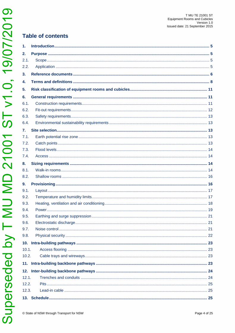
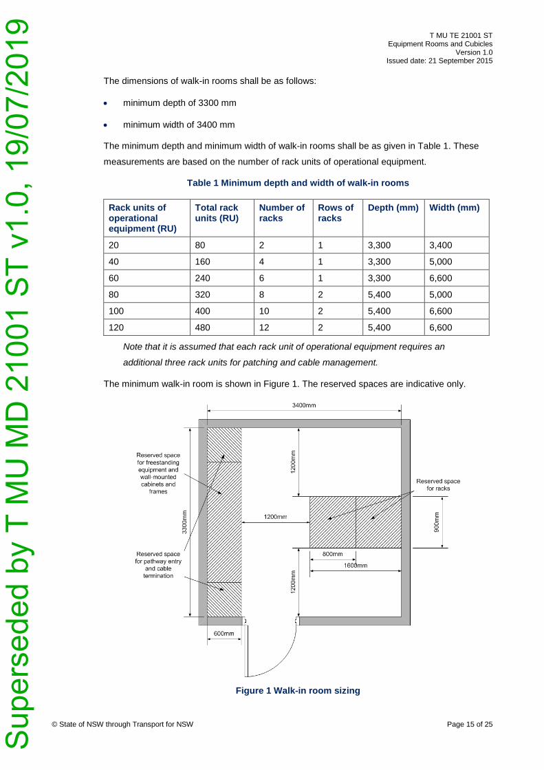
The dimensions of walk-in rooms shall be as follows:
• minimum depth of 3300 mm
• minimum width of 3400 mm
The minimum depth and minimum width of walk-in rooms shall be as given in Table 1. These
measurements are based on the number of rack units of operational equipment.
Table 1 Minimum depth and width of walk-in rooms
Rack units of operational equipment (RU)
Total rack units (RU)
Number of racks
Rows of racks
Depth (mm) Width (mm)
20 80 2 1 3,300 3,400
40 160 4 1 3,300 5,000
60 240 6 1 3,300 6,600
80 320 8 2 5,400 5,000
100 400 10 2 5,400 6,600
120 480 12 2 5,400 6,600
Note that it is assumed that each rack unit of operational equipment requires an
additional three rack units for patching and cable management.
The minimum walk-in room is shown in Figure 1. The reserved spaces are indicative only.
© State of NSW through Transport for NSW Page 15 of 25
Figure 1 Walk-in room sizing
Sup
erse
ded
by T
MU
MD
210
01 S
T v1
.0, 1
9/07
/201
9
T MU TE 21001 ST Equipment Rooms and Cubicles
Version 1.0 Issued date: 21 September 2015
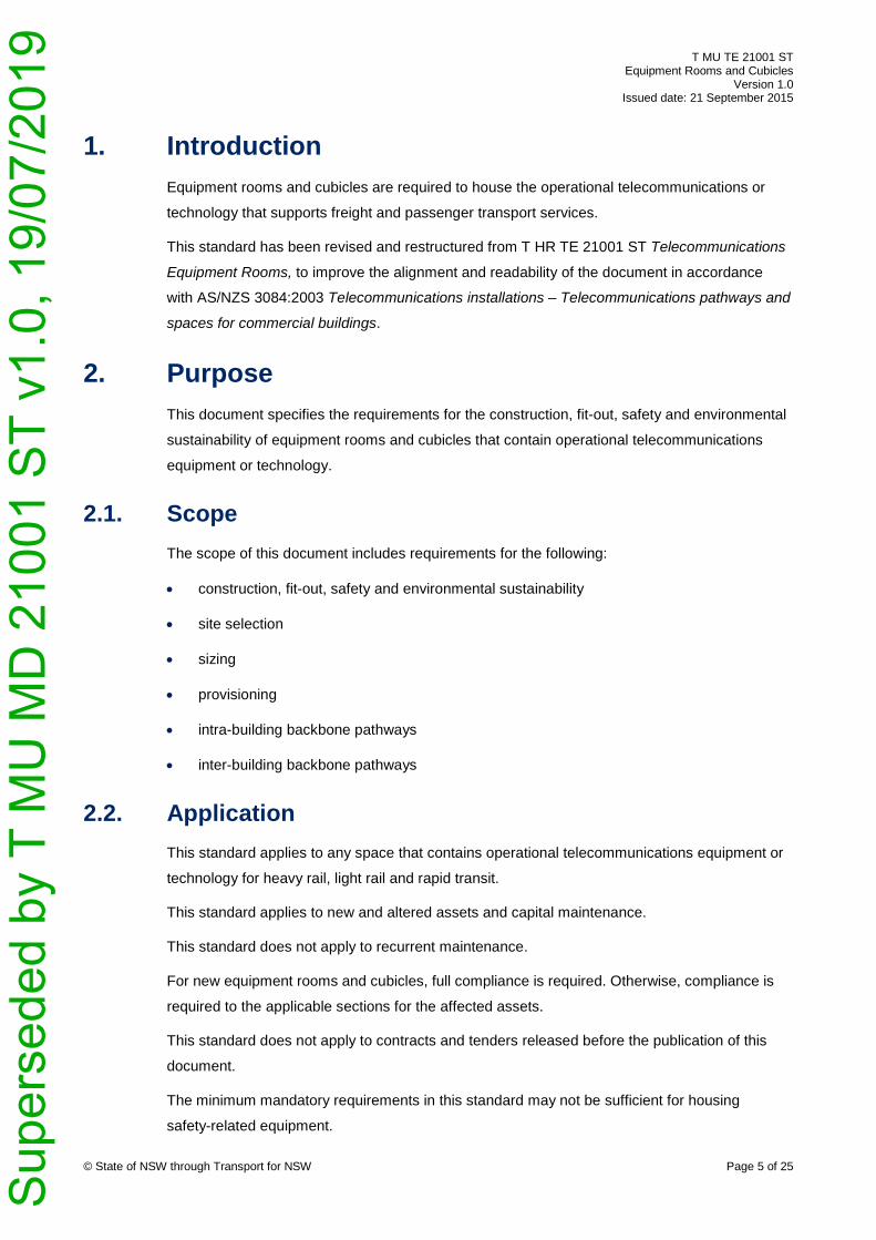
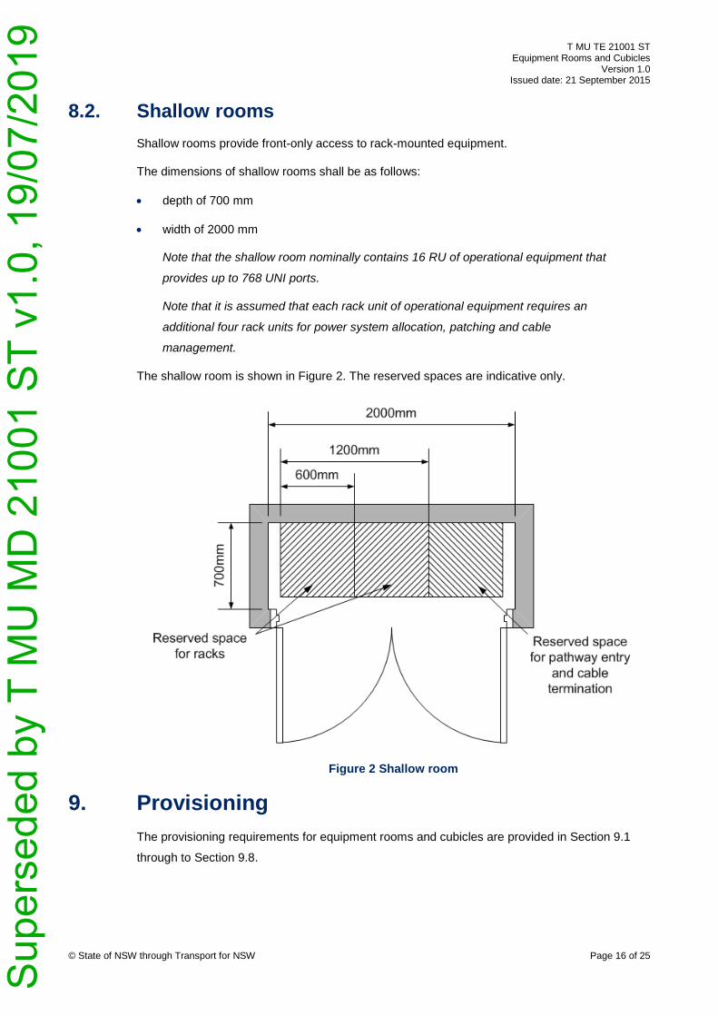
8.2. Shallow rooms Shallow rooms provide front-only access to rack-mounted equipment.
The dimensions of shallow rooms shall be as follows:
• depth of 700 mm
• width of 2000 mm
Note that the shallow room nominally contains 16 RU of operational equipment that
provides up to 768 UNI ports.
Note that it is assumed that each rack unit of operational equipment requires an
additional four rack units for power system allocation, patching and cable
management.
The shallow room is shown in Figure 2. The reserved spaces are indicative only.
© State of NSW through Transport for NSW Page 16 of 25
Figure 2 Shallow room
9. Provisioning The provisioning requirements for equipment rooms and cubicles are provided in Section 9.1
through to Section 9.8.
Sup
erse
ded
by T
MU
MD
210
01 S
T v1
.0, 1
9/07
/201
9
T MU TE 21001 ST Equipment Rooms and Cubicles
Version 1.0 Issued date: 21 September 2015
9.1. Layout The layout requirements for equipment rooms and cubicles are provided in Section 9.1.1
through to Section 9.1.2.
In equipment rooms, a space of a minimum of 600 mm wide and a minimum 600 mm deep shall
be reserved for each pathway entry for cable termination.
9.1.1. Racks and rails Operational equipment shall be mounted in racks or on rails in accordance with the
requirements stated in T HR TE 81001 ST Telecommunication Equipment – Physical Interfaces
and Environmental Conditions.
Racks shall be used to mount operational equipment in equipment rooms.
Racks or rails shall be used to mount operational equipment in cubicles.
In walk-in rooms, the maximum rack dimensions, including allowances for doors, shall be
800 mm wide, 900 mm deep (including 100 mm for front and rear rack doors) and provide 42
RU with front and back access.
In shallow rooms, the rack dimensions shall be 600 mm wide, 600 mm deep and provide 42 RU
with front access.
9.1.2. Clearance and pathways In walk-in rooms, a clearance of 1200 mm shall be maintained on the front and back of racks.
In walk-in rooms, an unimpeded egress pathway with a clearance width of 1200 mm shall be
provided as shown in Figure 1.
In walk-in rooms, the door shall open outwards to facilitate egress in an emergency.
In shallow rooms, a clearance of 1000 mm shall be maintained in front of the doors.
For cubicles, the concrete pad shall include a clearance of 1000 mm on all sides.
Note that where a clearance is specified it is derived from the maximum rack width or
depth with an additional clearance of 300 mm to allow for the decommissioning and
removal of equipment and racks.
9.2. Temperature and humidity limits The environmental conditions that equipment rooms or cubicles shall provide are defined in
section 9 of T HR TE 81001 ST and EN 50125-3 Railway applications – Environmental
conditions for equipment – Part 3: Equipment for signalling and telecommunications.
© State of NSW through Transport for NSW Page 17 of 25 S
uper
sede
d by
T M
U M
D 2
1001
ST
v1.0
, 19/
07/2
019
T MU TE 21001 ST Equipment Rooms and Cubicles
Version 1.0 Issued date: 21 September 2015
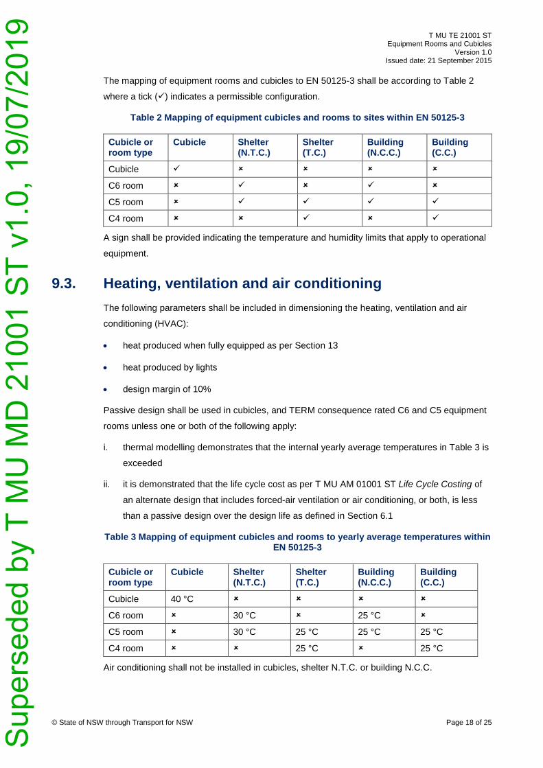
The mapping of equipment rooms and cubicles to EN 50125-3 shall be according to Table 2
where a tick () indicates a permissible configuration.
Table 2 Mapping of equipment cubicles and rooms to sites within EN 50125-3
Cubicle or room type
Cubicle Shelter (N.T.C.)
Shelter (T.C.)
Building (N.C.C.)
Building (C.C.)
Cubicle
C6 room
C5 room
C4 room
A sign shall be provided indicating the temperature and humidity limits that apply to operational
equipment.
9.3. Heating, ventilation and air conditioning The following parameters shall be included in dimensioning the heating, ventilation and air
conditioning (HVAC):
• heat produced when fully equipped as per Section 13
• heat produced by lights
• design margin of 10%
Passive design shall be used in cubicles, and TERM consequence rated C6 and C5 equipment
rooms unless one or both of the following apply:
i. thermal modelling demonstrates that the internal yearly average temperatures in Table 3 is
exceeded
ii. it is demonstrated that the life cycle cost as per T MU AM 01001 ST Life Cycle Costing of
an alternate design that includes forced-air ventilation or air conditioning, or both, is less
than a passive design over the design life as defined in Section 6.1
Table 3 Mapping of equipment cubicles and rooms to yearly average temperatures within EN 50125-3
Cubicle or room type
Cubicle Shelter (N.T.C.)
Shelter (T.C.)
Building (N.C.C.)
Building (C.C.)
Cubicle 40 °C
C6 room 30 °C 25 °C
C5 room 30 °C 25 °C 25 °C 25 °C
C4 room 25 °C 25 °C
Air conditioning shall not be installed in cubicles, shelter N.T.C. or building N.C.C.
© State of NSW through Transport for NSW Page 18 of 25 S
uper
sede
d by
T M
U M
D 2
1001
ST
v1.0
, 19/
07/2
019
T MU TE 21001 ST Equipment Rooms and Cubicles
Version 1.0 Issued date: 21 September 2015
Where forced-air ventilation or air conditioning is used, HVAC shall be designed with
redundancy such that if the primary system fails the secondary system can maintain the
temperature and humidity limits as defined in Section 9.2.
One of the following measures is required to mitigate the risk of dust ingress:
• the air intake to the room shall be filtered such that operational equipment may be installed
without requiring a specific degree of protection against solid foreign objects
• operational equipment installed in the room shall have a minimum IP code of IP5X
A sign shall be provided indicating the IP code constraints that apply to operational equipment.
Heating shall not be required to achieve the temperature limits as defined in Section 9.2.
9.4. Power Section 9.4.1 through to Section 9.4.4 specifies the power requirements for equipment rooms
and cubicles.
Unless indicated otherwise, socket-outlets shall comply with AS/NZS 3112 Approval and test
specification - Plugs and socket-outlets.
Power shall be supplied within tolerances of the operational equipment.
Power shall be supplied to the operational equipment and HVAC for the stand-by period
regardless of state or performance of all power sources.
9.4.1. Power source The following parameters shall be included in dimensioning the power source:
• power consumed when fully equipped as per Section 13
• rated power of ancillary circuits
• power consumed by lights
• peak power consumed by the HVAC to maintain the internal yearly average temperatures
in Table 3
• power consumption of energy storage system when charging
• minimum power conversion energy efficiency of 0.90
• design margin of 10%
Equipment rooms and cubicles shall be fitted with sensors compliant to T HR TE 81002 ST
Telecommunication Equipment – Network Management to monitor remaining storage capacity
and internal ambient temperature.
© State of NSW through Transport for NSW Page 19 of 25 S
uper
sede
d by
T M
U M
D 2
1001
ST
v1.0
, 19/
07/2
019
T MU TE 21001 ST Equipment Rooms and Cubicles
Version 1.0 Issued date: 21 September 2015
9.4.2. Stand-by power source
If an equipment room contains a public address system, a stand-by power source shall be
installed and comply with the power supply requirements defined in T MU TE 61003 ST Public
Address Systems.
A stand-by power source shall be installed in TERM consequence rated C5 and C4 equipment
rooms that are capable of supplying the full load of the operational equipment and HVAC for a
minimum stand-by period of four hours.
The life cycle cost of stand-by power sources shall be evaluated as per T MU AM 01001 ST
over the design life defined in Section 6.1 of this standard.
The life cycle costing shall evaluate the following options as a minimum:
• additional independent ac supply from an alternate electricity authority
• stationary battery or supercapacitor system
• uninterruptible power supply (UPS) system
• permanently connected generating set (diesel, natural gas, fuel cells, and so forth)
Where batteries are used as a stand-by power source, the following parameters shall be used
to dimension the batteries:
• temperature correction for internal yearly average temperatures as provided in Table 3
• aging factor of 25%
• design margin of 10%
Where lead-acid batteries are used, they shall be dimensioned according to IEEE 485
Recommended Practice for Sizing Lead-Acid Batteries for Stationary Applications.
Where a stand-by power source is provided, an appliance inlet shall be provided for connection
to a transportable generating set such as follows:
• an external wall mounted appliance inlet with a minimum IP code of IP66 and a minimum
IK code of IK06
• additionally labelled with the unique code for the equipment room or cubicle and the
minimum transportable generating set specification
The electrical installation to generating sets shall comply with AS/NZS 3010 Electrical
installations – Generating sets.
© State of NSW through Transport for NSW Page 20 of 25 S
uper
sede
d by
T M
U M
D 2
1001
ST
v1.0
, 19/
07/2
019
T MU TE 21001 ST Equipment Rooms and Cubicles
Version 1.0 Issued date: 21 September 2015
9.4.3. Operational equipment
A separate supply circuit for operational equipment shall be provided.
For equipment rooms, a 15 A socket-outlet with minimum IP code of IP44 coloured orange with
threaded retaining device shall be installed above each reserved space for racks and free
standing equipment.
Where dc supply is required for operational equipment, a 32 A two pole, extra low-voltage dc
socket-outlet compliant to IEC 60309-1 Plugs, socket-outlets and couplers for industrial
purposes - Part 1: General requirements with minimum IP code of IP44 shall be installed above
each reserved space for racks and freestanding equipment, and within cubicles.
9.4.4. Ancillary equipment A separate supply circuit for ancillary equipment shall be provided.
For equipment rooms, a double 10 A socket-outlet coloured white shall be installed for ancillary
equipment above each pair of rack spaces and above the freestanding equipment spaces.
For equipment rooms, a double 10 A socket-outlet coloured white shall be installed for ancillary
equipment on each internal wall.
For cubicles, a double 10 A ac socket-outlet coloured white shall be installed for ancillary
equipment.
Note that ancillary equipment should not be connected to the telecommunications
supply circuit.
9.5. Earthing and surge suppression The earthing and surge suppression requirements for equipment rooms and cubicles shall
comply with the requirements stated in T HR TE 21002 ST.
9.6. Electrostatic discharge TERM consequence rated C5 and C4 equipment rooms shall comply as an electrostatic
discharge protected area as defined in IEC 61340-5-1 Electrostatics – Part 5-1: Protection of
electronic devices from electrostatic phenomena – General requirements.
9.7. Noise control Noise control techniques shall be incorporated into the design for the expected tasks and
durations as defined in AS/NZS 1269.2 Occupational noise management - Noise control
management to achieve compliance to NSW Code of Practice – Managing Noise and
Preventing Hearing Loss at Work.
© State of NSW through Transport for NSW Page 21 of 25 S
uper
sede
d by
T M
U M
D 2
1001
ST
v1.0
, 19/
07/2
019
T MU TE 21001 ST Equipment Rooms and Cubicles
Version 1.0 Issued date: 21 September 2015
9.8. Physical security The physical security management of equipment rooms and cubicles shall comply with the
following guidelines:
• Australian Government Physical security management guidelines - Security zones and risk
mitigation controls
• Australian Government Physical security management guidelines - Physical security of ICT
equipment, systems and facilities
Note that the PSMG contain controls for the following:
• building construction
• out of hours alarm systems
• out of hours response
• access control systems
• locks
• keying systems
• interoperability of alarm system and other building management systems
• visitor control
• storage of official information
• storage of valuable physical assets
• CCTV coverage
• security lighting
• perimeter access control
• individual alarm options
• other controls to address specific risks
A security risk assessment shall determine the applicability of control components.
Table 4 provides requirements for physical security zones and containers.
Table 4 Physical security zones and containers
TERM consequence rating
Security zone
Security container
Additional mandatory controls
C6 Two Lockable racks • Windows and skylights are not permitted • Out of hours alarm system compliant to
AS 2201.1:2007 Class 3 © State of NSW through Transport for NSW Page 22 of 25 S
uper
sede
d by
T M
U M
D 2
1001
ST
v1.0
, 19/
07/2
019
T MU TE 21001 ST Equipment Rooms and Cubicles
Version 1.0 Issued date: 21 September 2015
TERM consequence rating
Security zone
Security container
Additional mandatory controls
C5 Two Lockable racks • Windows and skylights are not permitted • Out of hours alarm system compliant to
AS 2201.1:2007 Class 3
C4 Three Lockable racks • Windows and skylights are not permitted • Event-activated CCTV coverage used in
conjunction with the out of hours alarm system
• Additional geographically diverse equipment room and redundant system architecture across the two rooms
Note that the TERM consequence rating is aligned with the business impact levels, as
defined in Australian Government Physical security management guidelines –
Business impact levels:
• C6 and C5 aligns to ‘low-medium’ impacts on agency operations and national
infrastructure
• C4 aligns to ‘high’ impacts on agency operations and national infrastructure
10. Intra-building pathways Section 10.1 and Section 10.2 specifies the access floor requirements for equipment rooms and
cubicles.
10.1. Access flooring Access flooring may be used within TERM consequence rated C5 and C4 equipment rooms.
Access flooring shall be of a heavy grade and adjustable with stringers compliant with AS 4154
General access floors (elevated floors).
10.2. Cable trays and wireways A non-metallic cable tray shall be installed to provide a contiguous pathway between all
reserved spaces for racks and freestanding equipment.
11. Intra-building backbone pathways Intra-building backbone pathways interconnect equipment rooms and cubicles contained within
a single building.
Note this section is included for alignment to AS/NZS 3084:2003.
There are no additional requirements.
© State of NSW through Transport for NSW Page 23 of 25 S
uper
sede
d by
T M
U M
D 2
1001
ST
v1.0
, 19/
07/2
019
T MU TE 21001 ST Equipment Rooms and Cubicles
Version 1.0 Issued date: 21 September 2015
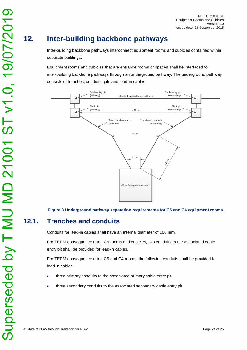
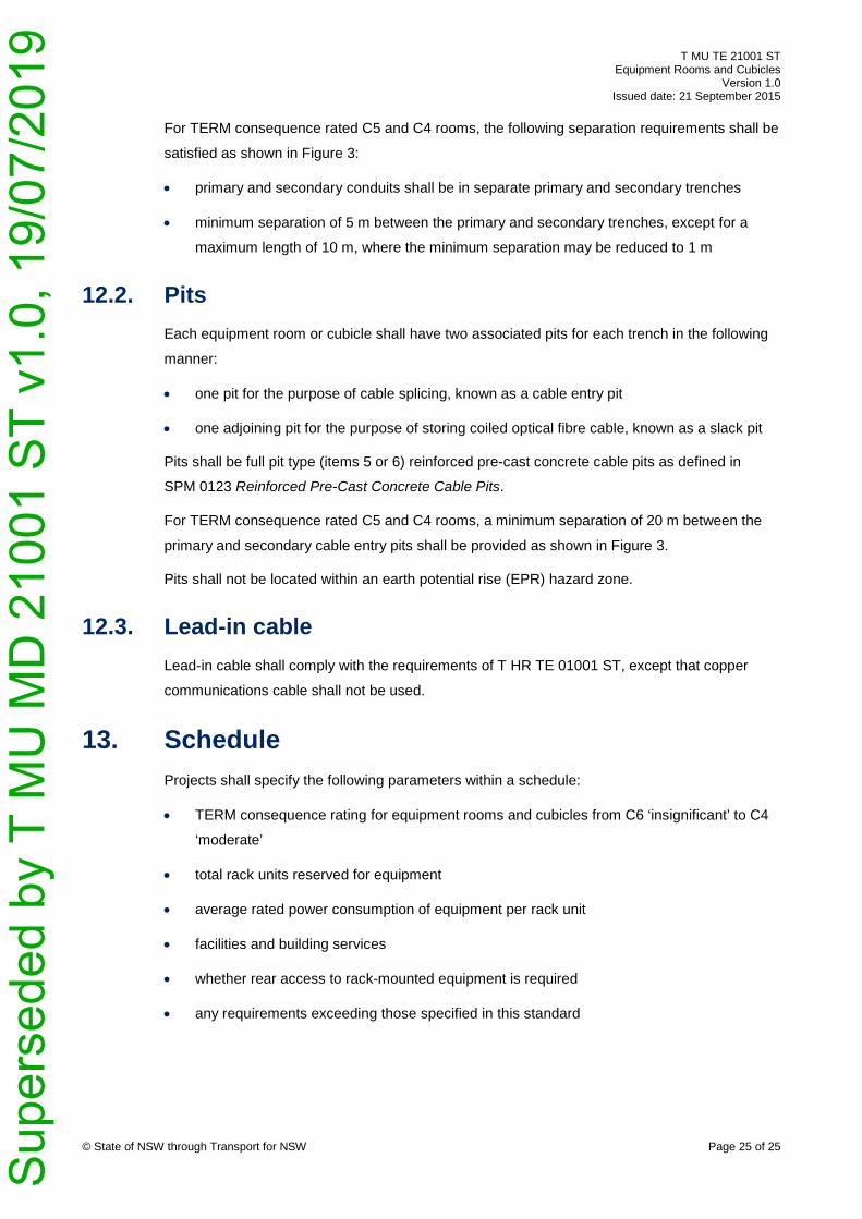
12. Inter-building backbone pathways Inter-building backbone pathways interconnect equipment rooms and cubicles contained within
separate buildings.
Equipment rooms and cubicles that are entrance rooms or spaces shall be interfaced to
inter-building backbone pathways through an underground pathway. The underground pathway
consists of trenches, conduits, pits and lead-in cables.
© State of NSW through Transport for NSW Page 24 of 25
Figure 3 Underground pathway separation requirements for C5 and C4 equipment rooms
12.1. Trenches and conduits Conduits for lead-in cables shall have an internal diameter of 100 mm.
For TERM consequence rated C6 rooms and cubicles, two conduits to the associated cable
entry pit shall be provided for lead-in cables.
For TERM consequence rated C5 and C4 rooms, the following conduits shall be provided for
lead-in cables:
• three primary conduits to the associated primary cable entry pit
• three secondary conduits to the associated secondary cable entry pit
Sup
erse
ded
by T
MU
MD
210
01 S
T v1
.0, 1
9/07
/201
9
T MU TE 21001 ST Equipment Rooms and Cubicles
Version 1.0 Issued date: 21 September 2015
For TERM consequence rated C5 and C4 rooms, the following separation requirements shall be
satisfied as shown in Figure 3:
• primary and secondary conduits shall be in separate primary and secondary trenches
• minimum separation of 5 m between the primary and secondary trenches, except for a
maximum length of 10 m, where the minimum separation may be reduced to 1 m
12.2. Pits Each equipment room or cubicle shall have two associated pits for each trench in the following
manner:
• one pit for the purpose of cable splicing, known as a cable entry pit
• one adjoining pit for the purpose of storing coiled optical fibre cable, known as a slack pit
Pits shall be full pit type (items 5 or 6) reinforced pre-cast concrete cable pits as defined in
SPM 0123 Reinforced Pre-Cast Concrete Cable Pits.
For TERM consequence rated C5 and C4 rooms, a minimum separation of 20 m between the
primary and secondary cable entry pits shall be provided as shown in Figure 3.
Pits shall not be located within an earth potential rise (EPR) hazard zone.
12.3. Lead-in cable Lead-in cable shall comply with the requirements of T HR TE 01001 ST, except that copper
communications cable shall not be used.
13. Schedule Projects shall specify the following parameters within a schedule:
• TERM consequence rating for equipment rooms and cubicles from C6 ‘insignificant’ to C4
‘moderate’
• total rack units reserved for equipment
• average rated power consumption of equipment per rack unit
• facilities and building services
• whether rear access to rack-mounted equipment is required
• any requirements exceeding those specified in this standard
© State of NSW through Transport for NSW Page 25 of 25 S
uper
sede
d by
T M
U M
D 2
1001
ST
v1.0
, 19/
07/2
019


![SummaryMap ward2 [Converted] · 2019-10-01 · MU-2 MU-6 MU-16 MU-14 MU-6 MU-2 MU-20 MU-9 MU-4 MU-13 MU-15 MU-13 MU-16 MU-18 MU-22 MU-19 MU-16 MU-27 MU-4 MU-3A MU-17 MU-13 MU-4](https://img.pdfslide.us/doc/110x75/5f5e4f591750d150e9633369/summarymap-ward2-converted-2019-10-01-mu-2-mu-6-mu-16-mu-14-mu-6-mu-2-mu-20.jpg)