Embed Size (px)
Citation preview

10/262/97
T
MOVIDRIVE® MD_60ADrive Inverters
Addendum to System Manual
Crane Control
Edition 02/200009
18 3
515
/ 022
000
UL®C UL®

2 MOVIDRIVE® Crane Control
Important Notes
• Read through this manual carefully before you commence installation and startup of thecrane control with MOVIDRIVE® drive inverters.This manual assumes that the user has access to and is familiar with the documentation onthe MOVIDRIVE® system, in particular the MOVIDRIVE® system manual.
• Safety notes:Always follow the safety and warning instructions contained in this manual!Safety notes are marked as follows:
Electrical hazard, e.g. during live working.
Mechanical hazard, e.g. when working on hoists.
Important instructions for safe and fault-free operation of the driven machine/sys-tem, e.g. pre-setting before startup.
• In this manual, cross references are marked with a →, e.g.:(→ MX_SCOPE) means: Please refer to the MX_SCOPE manual for detailed information orinformation on how to carry out this instruction.(→ Sec. X.X) means: Further information can be found in section X.X of this manual.
• Each unit is manufactured and tested to current SEW-EURODRIVE technical standards andspecifications.A requirement of fault-free operation and fulfillment of any rights to claim under guarantee isthat this information is observed.This manual contains important information about servicing; as a result, it should be kept inthe vicinity of the unit.
• This supplementary information does not replace the detailed operating instructions!• Installation should only be performed by electrical specialists observing applicable acci-
dent prevention regulations and the MOVIDRIVE® operating instructions!

Contents
MOVIDRIVE® Crane Control 3
Page
1 Project Planning ........................................................................................41.1 Application fields ............................................................................................................. 41.2 Pre-requisites ..................................................................................................................4
1.2.1 PC and software ...............................................................................................41.2.2 Inverters, motors and encoders .......................................................................4
1.3 Functional description......................................................................................................51.4 Limit switches..................................................................................................................5
2 Installation...............................................................................................62.1 Software ..........................................................................................................................62.2 Terminal assignment and wiring diagrams ......................................................................72.3 Control inputs ..................................................................................................................92.4 Limit switch connections ...............................................................................................11
3 Startup.................................................................................................. 123.1 General information .......................................................................................................123.2 Preliminary work............................................................................................................123.3 Starting the “crane control” program.............................................................................12
3.3.1 Setting the speed limits and the operating mode ........................................... 133.3.2 Setting fixed setpoints....................................................................................143.3.3 Setting ramps for fixed setpoint operating mode ........................................... 153.3.4 Setting ramps for motor potentiometer operating mode ................................16
3.4 Parameter ......................................................................................................................18
4 Operation and Service ............................................................................... 194.1 General information .......................................................................................................194.2 Sequence diagram for motor potentiometer ..................................................................204.3 Sequence diagram for fixed setpoints............................................................................224.4 Making contact with limit switches (in “motor potentiometer” mode) ...........................244.5 Fault messages ..............................................................................................................26

4 MOVIDRIVE® Crane Control
1 Project Planning
1 Project Planning
1.1 Application fields
Crane control is particularly well suited to the materials handling and logistics industries. The fol-lowing applications represent examples of these:
• Trolleys• Hoists
• Trolley travelling winches
• Construction cranesThe drives can be operated manually or by remote control.
The crane control offers the following advantages in these applications:
• Wide range of functions• User-friendly user interface
• You only have to enter the parameters required for the crane control (operating modes, speeds,fixed setpoints, ramps)
• User-friendly application programs guide you through the process of setting parameters, sothere is no need for complicated programming
• You do not need any programming experience
• It doesn’t take long to get to know the system
1.2 Pre-requisites
1.2.1 PC and software
The crane control is implemented as an IPOSplus® program and forms part of the SEW MOVITOOLS software package. In order to use MOVITOOLS, you must have a PC with one of thefollowing operating systems: Windows 95® , Windows 98® or Windows NT® version 4.0.
1.2.2 Inverters, motors and encoders
• Inverters
The crane control function can be implemented with all MOVIDRIVE® MD_60A (MDF60A,MDV60A and MDS60A) drive inverters. MOVIDRIVE® MD_60A must be equipped with theDIO11A input/output interface option (part number 822 726 8) for crane control. Please refer tothe MOVIDRIVE® MD_60A operating instructions (Installation section) for information aboutinstalling options.
• Motors
– For operation on MOVIDRIVE® MDF60A:
AC motors DT/DV/D without incremental encoder.– For operation on MOVIDRIVE® MDV60A:
Asynchronous servo motors CT/CV, encoder installed as standard.
AC motors DT/DV/D with incremental encoder option.– For operation on MOVIDRIVE® MDS60A:
Synchronous servo motors DS/DY, resolver installed as standard.

MOVIDRIVE® Crane Control 5
Project Planning 1
1.3 Functional description
The crane control provides the following functional characteristics:
• 6 fixed setpoints for multi-stage switching• Variable speed in motor potentiometer mode
• Monitoring of preliminary and main limit switches
• Speed reduction to nmin or n11 (stage 1) when the preliminary limit switch is reached• Max. speed limitation depending on load (load detection)
• Implementation of crane control in all operating modes (VFC, VFC-n-CONTROL, CFC, SERVO)
• Automatic programming of the input/output terminals required
The functions are implemented with two operating modes:
• Motor potentiometer mode (floor control)
– Drive enable for CW or CCW operation with 2 binary inputs– Infinitely variable speed setting with both motor potentiometer up/down buttons
– Fine positioning of the drive with nmin
– Max. speed limitation depending on load (load detection)
• Fixed setpoint mode (radio control)
– Selection of fixed setpoints n11, n12, n13, n21, n22 or n23 using binary inputs– Max. speed limitation depending on load (load detection)
1.4 Limit switches
An extensive limit switch monitoring function monitors the preliminary and main limit switches inthe travel range. The limit switches must be low active (“0” = Contact with limit switch, “1” = Nocontact). You must select the type of preliminary limit switch with the long cams.
• If contact is made with the preliminary limit switch, the speed is reduced to nmin (motor potenti-ometer mode) or n11 (fixed setpoint mode).
• The drive is stopped when contact is made with the main limit switches.
• Limit switch monitoring is active in both operating modes.

6 MOVIDRIVE® Crane Control
2 Installation
2 Installation
2.1 Software
Crane control is a part of the SEW MOVITOOLS software package. Proceed as follows to installMOVITOOLS on your computer:
1. Insert the MOVITOOLS CD into the CD ROM drive of your PC.2. Select “Start/Run...”.3. Type “{Drive letter of your CD drive}:setup” and press the Enter key.4. The MOVITOOLS setup menu appears. Follow the instructions of the installation wizard.
Now proceed as follows to install the crane control software:1. Insert disk 1/2 with the crane control into the disk drive of your PC.2. Select “Start/Run...”.3. Type “{Drive letter of your floppy disk drive}:setup” and press the Enter key.4. The crane control setup menu appears. Follow the instructions of the installation wizard.
You can now use Program Manager to start MOVITOOLS. If a MOVIDRIVE® unit is connected toyour PC, select the correct port (PC COM port) and set point-to-point connection. Select <Update>to display the inverter in the “Connected Units” window.
02745AENFig. 1: MOVITOOLS window

MOVIDRIVE® Crane Control 7
Installation 2
2.2 Terminal assignment and wiring diagrams
The IPOSplus® program automatically programs the binary inputs with the following functions:
Basic unit X13:2 – X13:6 (DIØ1 – DIØ5) ⇒ “IPOS input”DIO11A option X22:1 (DI1Ø) ⇒ “/CW LIMIT SWITCH”
X22:2 (DI11) ⇒ “/CCW LIMIT SWITCH”
X22:3/X22:4 (DI12/DI13) ⇒ “IPOS input”X22:5 (DI14) ⇒ “Reset”
X22:6 (DI15) ⇒ “IPOS input”
X22:7 (DI16) ⇒ “No function”
X22:8 (DI17) ⇒ “Reserved”
Do not reprogram the binary inputs!
Important: Binary input X22:8 (DI17) must have a fixed connection to DGND.
This terminal assignment is the same for either operating mode, motor potentiometer or fixed set-point. The function of the binary inputs programmed with “IPOS input” is defined by the IPOSplus®
program. The function is shown in the following wiring diagrams.
Motor potentiometer mode
02634AENFig. 2: Wiring diagram for motor potentiometer mode
X13:DIØØDIØ1DIØ2DIØ3DIØ4DIØ5
DCOMVO24DGNDST11ST12
123456789
1011RS-485-
RS-485+
X22:DI1ØDI11DI12DI13DI14DI15DI16DI17
DCOMDGND
123456789
10
CONTROL
IPOSInput
CW main limit switchCCW main limit switchCW preliminary limit switchCCW preliminary limit switchError ResetSwitchover operating modeMotor potentiometer/fixed setpoints
CW/StopCCW/StopMotor pot. upMotor pot. downreserved
IPOSInputIPOSInput
Ref. potential for binary signals
/LSCW/LSCCW
IPOSInputIPOSInput
Reset
CW/StopReference X22:DI1Ø...DI17
DIO11A Option
Ref. potential for binary signals
Reference X13:DIØØ...DIØ5+24Voutput
Controlunit
IPOSInput
/Controller inhibitIPOSInputIPOSInput

8 MOVIDRIVE® Crane Control
2 Installation
Fixed setpoint mode
02635AENFig. 3: Wiring diagram for fixed setpoint mode
The 6 fixed setpoints are selected with binary coding using binary inputs X13:4 (DIØ3) – X13:4(DIØ5) in fixed setpoint mode.
nmin is in effect when the inverter is enabled if no fixed setpoint has been selected, i.e. X13:4, X13:5and X13:6 = “0”.
Fixed setpoint X13:4 (DIØ3) = Speed 2^0 X13:5 (DIØ4) = Speed 2^1 X13:6 (DIØ5) = Speed 2^2
n11 (stage 1) “1” “0” “0”
n12 (stage 2) “0” “1” “0”
n13 (stage 3) “1” “1” “0”
n14 (stage 4) “0” “0” “1”
n22 (stage 5) “1” “0” “1”
n23 (stage 6) “0” “1” “1”
X13:DIØØDIØ1DIØ2DIØ3DIØ4DIØ5
DCOMVO24DGNDST11ST12
123456789
1011RS-485-
RS-485+
X22:DI1ØDI11DI12DI13DI14DI15DI16DI17
DCOMDGND
123456789
10
CONTROL
CW main limit switchCCW main limit switchCW preliminary limit switchCCW preliminary limit switchError ResetSwitchover operating modeMotor potiometer/fixed setpoints
CW/StopCCW/StopVelocity 2^0Velocity 2^1Velocity 2^2
IPOSInputIPOSInput
Ref. potential for binary signals
/LSCW/LSCCW
IPOSInputIPOSInput
ResetIPOSInput
Rechts/HaltReference X22:DI1Ø...DI17
DIO11A Option
Ref. potential for binary signals
Reference X13:DIØØ...DIØ5+24Voutput
Controlunit
IPOSInput
/Controller inhibitIPOSInputIPOSInput

MOVIDRIVE® Crane Control 9
Installation 2
2.3 Control inputs
It is possible to select between two operating modes for crane control. Binary input X22:6 (DI15) isused for switching between the operating modes:
X22:6 (DI15) = “0” ⇒ Motor potentiometer mode (floor control)
X22:6 (DI15) = “1” ⇒ Fixed setpoint mode (radio control)
Binary inputs X13:4 – X13:6 (DIØ3 – DIØ5) are evaluated differently depending on the operatingmode setting.
Binary input X22:5 (DI14) has “Reset” assigned to it and it is not required for crane control. It isprovided in the event of a malfunction, to make it possible to perform a reset using the terminals.
The information given in the following tables assumes that ramp set 1 (P130 – P133) in parameterset 1 is used.
Motor potentiometer mode, X22:6 (DI15) = “0”:
*) Emergency stop:
The drive is braked with the emergency ramp t14/t24. Once the stop speed is reached, the brake isapplied (DBØØ “/Brake” = “0”). The output stage goes to high-resistance after the brake reactiontime has elapsed (P732 / P735).
Binary input Function “1” signal “0” signal
X13:1 (DIØØ) /Controller inhibit Output stage not inhibited Output stage not inhibited
X13:2 (DIØ1) CW/STOP CW enable, ramp t11 up CW (P130) until nmin
Stop with ramp t11 down CW(P131)
X13:3 (DIØ2) CCW/STOP CCW enable, ramp t11 up CCW (P132) until nmin
Stop with ramp t11 down CCW(P133)
X13:4 (DIØ3) Motor potentiometer upRamp t3 up (P150) in the direction of rotation specified with X13:2 and
X13:3 until max. nmax
Current setpoint remains unchanged
X13:5 (DIØ4) Motor potentiometer down Ramp t3 down (P151) until nmin Current setpoint remains unchanged
X22:1 (DI1Ø) CW main limit switch
Status within the travel range
Contact with CW main limit switch→ Emergency stop*) with ramp t14
(P137)
X22:2 (DI11) CCW main limit switchContact with CCW main limit switch→ Emergency stop*) with ramp t14
(P137)
X22:3 (DI12) CW preliminary limit switch
Contact with CW preliminary limit switch
→ Deceleration with ramp t13 (P136) until nmin
X22:4 (DI13) CCW preliminary limit switch
Contact with CCW preliminary limit switch
→ Deceleration with ramp t13 (P136) until nmin

10 MOVIDRIVE® Crane Control
2 Installation
Fixed setpoint mode, X22:6 (DI15) = “1”:
*) Emergency stop:
The drive is braked with the emergency ramp t14/t24. Once the stop speed is reached, the brake isapplied (DBØØ “/Brake” = “0”). The output stage goes to high-resistance after the brake reactiontime has elapsed (P732 / P735).
Binary coding of the fixed setpoints:
nmin is in effect when the inverter is enabled if no fixed setpoint has been selected, i.e. X13:4, X13:5and X13:6 = “0”.
Binary input Function “1” signal “0” signal
X13:1 (DIØØ) /Controller inhibit Output stage not inhibited Output stage not inhibited
X13:2 (DIØ1) CW/STOP CW enable, ramp t11 up CW (P130) until nmin
Stop with ramp t11 down CW(P131)
X13:3 (DIØ2) CCW/STOP CCW enable, ramp t11 up CCW (P132) until nmin
Stop with ramp t11 down CCW(P133)
X13:4 (DIØ3) Speed 2^0The fixed setpoints n11, n12, n13, n21, n22 and n23 are selected with binary
coding (→ table below).X13:5 (DIØ4) Speed 2^1
X13:6 (DIØ5) Speed 2^2
X22:1 (DI1Ø) CW main limit switch
Status within the travel range
Contact with CW main limit switch→ Emergency stop*) with ramp t14
(P137)
X22:2 (DI11) CCW main limit switchContact with CCW main limit switch→ Emergency stop*) with ramp t14
(P137)
X22:3 (DI12) CW preliminary limit switch
Contact with CW preliminary limit switch
→ Deceleration with ramp t13 (P136) until nmin
X22:4 (DI13) CCW preliminary limit switch
Contact with CCW preliminary limit switch
→ Deceleration with ramp t13 (P136) until nmin
Fixed setpoint X13:4 (DIØ3) = Speed 2^0 X13:5 (DIØ4) = Speed 2^1 X13:6 (DIØ5) = Speed 2^2
n11 (stage 1) “1” “0” “0”
n12 (stage 2) “0” “1” “0”
n13 (stage 3) “1” “1” “0”
n14 (stage 4) “0” “0” “1”
n22 (stage 5) “1” “0” “1”
n23 (stage 6) “0” “1” “1”

MOVIDRIVE® Crane Control 11
Installation 2
2.4 Limit switch connections
Track limit switch processing for cranes is supported. There is a total of four limit switch inputs formonitoring the travel distance and the travel speed.
Option DIO11A X22:1 (DI1Ø) ⇒ CW main limit switch
X22:2 (DI11) ⇒ CCW main limit switchX22:3 (DI12) ⇒ CW preliminary limit switch
X22:4 (DI13) ⇒ CCW preliminary limit switch
The limit switches must be attached to the travel range in accordance with Fig. 4. Only low-activelimit switches may be used for reasons of safety. The limit switch monitoring function in the unitchecks that both preliminary and main limit switches are connected when the inverter is enabled.
Limit switch inputs which are not in use must be connected to +24 V (X13:8 VO24), otherwise faultmessage F27 “Limit switches missing” is generated by the limit switch monitoring function.
02657AENFig. 4: Arrangement of limit switches
The cams for the preliminary and main limit switches must overlap (long cams). The cams of thelimit switches must cover the travel range up to the stop.
(with
long
cam
s)
(with
long
cam
s)
CW p
relim
inar
y lim
it sw
itch
CW m
ain li
mit
switc
h
Distance of travel
CW drive inverter
CCW
pre
limin
ary
limit
switc
h
CCW
main
lim
it sw
itch

12 MOVIDRIVE® Crane Control
3 Startup
3 Startup
3.1 General information
Correct project planning and installation are the pre-requisites for successful startup. Refer to theMOVIDRIVE® system manual for detailed project planning instructions. The system manual formspart of the MOVIDRIVE® documentation package (publication number 0919 3200).
Check the installation, including the encoder connection and the installation of the input/outputinterface type DIO11A, by following the installation instructions in the MOVIDRIVE® MD_60A operating instructions and in this manual (Sec. 2, page 6).
3.2 Preliminary work
Perform the following steps before the startup of “crane control”:• Connect the inverter to the PC using the serial port (RS-232, USS21A on PC-COM).
• Install MOVITOOLS on the PC (Sec. 2.1, page 6) and start the program.
• Start up the inverter using <Shell>.– With MOVIDRIVE® MDF60A and DT/DV/D motors, in VFC operating mode.
– With MOVIDRIVE® MDV60A and DT/DV/D motors, in VFC-n-CONTROL operating mode.
– With MOVIDRIVE® MDV60A and CT/CV motors, in CFC operating mode.– With MOVIDRIVE® MDS60A and DS/DY motors, in SERVO operating mode.
• “0” signal at terminal X13:1 (DIØØ, /Controller inhibit).
3.3 Starting the “crane control” program
• Start <Shell>.
• In Shell, start “Startup/Crane control”.
02994AENFig. 5: Starting the “crane control” program

MOVIDRIVE® Crane Control 13
Startup 3
3.3.1 Setting the speed limits and the operating mode
When the crane control starts, the window for setting the speed limits and the operating modeappears.
02995AENFig. 6: Setting the speed limits and the operating mode
You have to make the following settings in this window:
• Speed limits
• Speeds after contacting a preliminary limit switchThe slow speed is identical to P301 Minimum speed 1 (nmin) and cannot be set at this point.
• Operating mode
Set the required operating mode. You can also select both operating modes and switch modesduring operation using X22:6 DI15 “Fixed setpoint switchover”.
Press “Next >>”, after which the next startup window appears.

14 MOVIDRIVE® Crane Control
3 Startup
3.3.2 Setting fixed setpoints
This window only appears if you have selected the fixed setpoint operating mode.
02997AENFig. 7: Setting fixed setpoints
Set the required values for the fixed setpoints. You cannot set the value for stage 1 (n11) becausethis is defined by the setting for the speed when contact is made with a preliminary limit switch.
Press “Next >>”, after which the next startup window appears.

MOVIDRIVE® Crane Control 15
Startup 3
3.3.3 Setting ramps for fixed setpoint operating mode
This window only appears if you have selected the fixed setpoint operating mode.
02998AENFig. 8: Setting fixed setpoint ramps
Set the ramps for fixed setpoint operating mode.
Press “Next >>”, after which the next startup window appears.

16 MOVIDRIVE® Crane Control
3 Startup
3.3.4 Setting ramps for motor potentiometer operating mode
This window only appears if you have selected the motor potentiometer operating mode.
02996AENFig. 9: Setting motor potentiometer ramps
Set the ramps for motor potentiometer operating mode (variable speed preselection).
Press “Next>>” when you have entered the values you want. The program prompts you to save thevalues you have set. The download window appears after the settings have been saved.

MOVIDRIVE® Crane Control 17
Startup 3
Press <Download>. All necessary settings are automatically made in the inverter and the “Cranecontrol” IPOS program is started.
02999AENFig. 10: Download window
AUTO

18 MOVIDRIVE® Crane Control
3 Startup
3.4 Parameter
The crane control startup automatically sets the following parameters:
These parameters must not be altered after startup!
Parameter number Parameter Setting
100 Setpoint source MOTOR POTENTIOM.
101 Control signal source TERMINALS
130 t11 up CW 0 – 2000 s
131 t11 down CW 0 – 2000 s
132 t11 up CCW 0 – 2000 s
133 t11 down CCW 0 – 2000 s
136 t13 (STOP ramp) 0 – 20 s
150 t3 up 0.2 – 50 s
151 t3 down 0.2 – 50 s
160 n11 -5000 – 5000 rpm
161 n12 -5000 – 5000 rpm
162 n13 -5000 – 5000 rpm
170 n21 -5000 – 5000 rpm
171 n22 -5000 – 5000 rpm
172 n23 -5000 – 5000 rpm
301 Minimum speed 1 0 – 5500 rpm
302 Maximum speed 1 0 – 5500 rpm
600...604 Binary inputs DIØ1 – DIØ5 IPOS input
610 Binary input DI1Ø /CW limit switch
611 Binary input DI11 /CCW limit switch
612/613 Binary inputs DI12/DI13 IPOS input
614 Binary input DI14 Reset
615 Binary input DI15 IPOS input
616 Binary input DI16 No function
617 Binary input DI17 Reserved

MOVIDRIVE® Crane Control 19
Operation and Service 4
4 Operation and Service
4.1 General information
The crane control operating modes are described using sequence diagrams.It is permitted to switch over from “motor potentiometer” mode to “fixed setpoint” mode duringoperation and vice versa. Binary input X22:6 (DI15) is used for switching over:• X22:6 (DI15) = “0”→ Motor potentiometer mode
• X22:6 (DI15) = “1”→ Fixed setpoint mode
Speed ramps and fixed setpoints used:
Selecting fixed setpoints:All 6 fixed setpoints can be selected in “fixed setpoint” operating mode. It is not necessary tochange parameter sets in order to do this.The fixed setpoints are selected using binary code with binary inputs X13:4 (DIØ3) – X13:6 (DIØ5).
Note:
The sequence diagram uses the speed ramps and fixed setpoints of parameter set 1.
Speed ramps Parameter set 1
CW/STOP t11 up CW (P130)t11 down CW (P131)
CCW/STOP t11 up CCW (P132)t11 down CCW (P133)
Motor potentiometer up t3 up (P150)
Motor potentiometer down t3 down (P151)
Stop (preliminary limit switch) t13 (P136)
Emergency stop (main limit switch) t14 (P137)
Fixed setpoints Parameter set 1 Parameter set 2
1st fixed setpoint n11 (P160) n21 (P170)
2nd fixed setpoint n12 (P161) n22 (P171)
3rd fixed setpoint n13 (P162) n23 (P172)
Fixed setpoint X13:4 (DIØ3) = Speed 2^0 X13:5 (DIØ4) = Speed 2^1 X13:6 (DIØ5) = Speed 2^2
n11 (stage 1) "1" “0” “0”
n12 (stage 2) “0” “1” “0”
n13 (stage 3) “1” “1” “0”
n14 (stage 4) “0” “0” “1”
n22 (stage 5) “1” “0” “1”
n23 (stage 6) “0” “1” “1”

20 MOVIDRIVE® Crane Control
4 Operation and Service
4.2 Sequence diagram for motor potentiometer
02658AENFig. 11: Sequence diagram for motor potentiometer
Important:
The drive must be enabled with X13:1 (DIØØ) /CONTROLLER INHIBIT = “1”.
nn
"0"
"1"
"1"
"0"
"1"
"1"
"1"
"0"
"0"
"0"0
n min
n sta
rt/st
op
n min
n sta
rt/st
op
n max
n max
t13
01
23
45
67
89
1011
X10:
3(D
BØØ)
/bra
ke
X13:
5(D
IØ4)
Mot
orpo
t.do
wn
X13:
4(D
IØ3)
Mot
orpo
t.up
X13:
3(D
IØ2)
CCW
/Sto
p
X13:
2(D
IØ1)
CW/S
top
Requ
estf
orre
vers
alof
rota
tion
dire
ctio
n
t11
dow
nCW
t3do
wn
t3up
t3up
t11
upCW
t11
upCC
Wt3
up
t11
upCC
W
t11
dow
nCW
t3do
wn
t3up
t11
upCW
CWop
erat
ion
CCW
oper
atio
n
Cycl
e

MOVIDRIVE® Crane Control 21
Operation and Service 4
Explanation of the sequence diagram for motor potentiometer• Tl. X13:1 (DIØØ) /CONTROLLER INHIBIT = “1”
• Cycle 1: Tl. X13:2 (DIØ1) CW/stop from “0” to “1”
- Clockwise and tl. X10:3 (DBØØ) /Brake from “0” to “1”, i.e. the brake is released. Accelerationwith ramp t11 up CW until nmin, nmin is then maintained.
• Cycle 2: Tl. X13:4 (DIØ3) motor potentiometer up from “0” to “1”
- Acceleration with motor potentiometer ramp t3 up as long as there is a “1” signal at X13:4.Current setpoint is maintained with a “0” signal at X13:4 and X13:5 and X13:2 ≠ X13:3.
• Cycle 3: Tl. X13:4 (DIØ3) motor potentiometer up from “0” to “1”- Acceleration with motor potentiometer ramp t3 up until nmax. nmax is maintained when there
is a “0” signal at X13:5 and X13:2 ≠ X13:3.
• Cycle 4: Tl. X13:5 (DIØ4) motor potentiometer down from “0” to “1”- Deceleration with motor potentiometer ramp t3 down as long as there is a “1” signal at X13:5
or until nmin is reached.
• Cycle 5: Tl. X13:2 (DIØ1) CW/stop from “1” to “0”- Deceleration with ramp t11 down CW from nmin to nstart/stop, then stop and X10:3 (DBØØ) /
Brake from “1” to “0”, i.e. the brake is applied.
• Cycle 6: Tl. X13:3 (DIØ2) CCW/stop from “0” to “1”- Counterclockwise and tl. X10:3 (DBØØ) /Brake from “0” to “1”, i.e. the brake is released. The
drive accelerates with ramp t11 up CCW until nmin, nmin is then maintained.
• Cycle 7: Tl. X13:4 (DIØ3) motor potentiometer up from “0” to “1”- Acceleration with motor potentiometer ramp t3 up until nmax. nmax is maintained when there
is a “0” signal at X13:5 and X13:2 ≠ X13:3.
• Cycle 8: Tl. X13:2 (DIØ1) CW/stop from “0” to “1”- Deceleration with motor potentiometer ramp t11 down CCW as long as X13:2 = X13:3. If
X13:3 changes from “1” to “0”, i.e. X13:2 ≠ X13:3, deceleration with ramp t13 until stop, thenchange of direction of rotation and acceleration with ramp t11 up CW until nmin. If X13:4 =“0”, nmin is maintained; if X13:4 = “1” acceleration with motor potentiometer ramp t3 up.
• Cycle 9: Tl. X13:4 (DIØ3) motor potentiometer up from “1” to “0”
- Current setpoint is maintained when “0” signal at X13:4 and X13:5 and X13:2 ≠ X13:3.
• Cycle 10: Tl. X13:2 (DIØ1) CW/stop from “1” to “0”
- Deceleration with ramp t3 down until nmin and ramp t11 down CW from nmin to nstart/stop, then stopand X10:3 (DBØØ) /Brake from “1” to “0”, i.e. the brake is applied.
Refer to Sec. 4.4 (page 24) for information about making contact with limit switches.

22 MOVIDRIVE® Crane Control
4 Operation and Service
4.3 Sequence diagram for fixed setpoints
02659AENFig. 12: Sequence diagram for fixed setpoints
Important:The drive must be enabled with X13:1 (DIØØ) /CONTROLLER INHIBIT = “1”.
nn
"0"
"1"
"1"
"0"
"1"
"1"
"1"
"0"
"0"
"0"0
n min
n sta
rt/st
op
n min
n sta
rt/st
op
n13
n12
n11
n13
n12
n11
t11
dow
nCC
W
t11
dow
nCC
W
01
23
45
67
89
1011
X10:
3(D
BØØ)
/bra
ke
X13:
5(D
IØ4)
Velo
city
2^1
X13:
4(D
IØ3)
Velo
city
2^0
X13:
3(D
IØ2)
CCW
/Sto
p
X13:
2(D
IØ1)
CW/S
top
Requ
estf
orre
vers
alof
rota
tion
dire
ctio
n
t11
dow
nCW
t11
upCW
t11
upCW
t11
upCC
W
t11
upCW
t11
upCW
CWro
t.
CCW
rot.Cy
cle
t11
upCW
t13

MOVIDRIVE® Crane Control 23
Operation and Service 4
Explanation of the sequence diagram for fixed setpoints• Tl. X13:1 (DIØØ) /CONTROLLER INHIBIT = “1”
• Cycle 1: Tl. X13:2 (DIØ1) CW/stop from “0” to “1”- Clockwise and tl. X10:3 (DBØØ) /Brake from “0” to “1”, i.e. the brake is released. Acceleration
with ramp t11 up CW until nmin, nmin is then maintained.
• Cycle 2: Tl. X13:4 (DIØ3) speed 2^0 from “0” to “1”
- Acceleration with ramp t11 up CW to fixed setpoint n11.
• Cycle 3: Tl. X13:4 (DIØ3) speed 2^0 from “1” to “0” and tl. X13:5 (DIØ4) speed 2^1 from “0” to“1”- Acceleration with ramp t11 up CW to fixed setpoint n12.
• Cycle 4: Tl. X13:5 (DIØ4) speed 2^1 = “1” and tl. X13:4 (DIØ3) speed 2^0 from “0” to “1”- Acceleration with ramp t11 up CW to fixed setpoint n13.
• Cycle 5: Tl. X13:2 (DIØ1) CW/stop from “1” to “0” and tl. X13:3 (DIØ2) CCW/stop from “0” to“1”
- Deceleration with ramp t13 until stop, then change of direction of rotation and accelerationwith ramp t11 up CCW to fixed setpoint n13.
• Cycle 6: Tl. X13:3 (DIØ2) CCW/stop; X13:4 (DIØ3) speed 2^0 and X13:5 (DIØ5) speed 2^1 = “1”
- Acceleration with ramp t11 up CCW to fixed setpoint n13.
• Cycle 7: Tl. X13:4 (DIØ3) speed 2^0 and X13:5 (DIØ4) speed 2^1 from “1” to “0”
- Deceleration with ramp t11 down CCW until nmin.
• Cycle 8: Tl. X13:3 (DIØ2) CCW/stop = “1” and X13:2 (DIØ1) CW/stop from “0” to “1”
- Deceleration with ramp t11 down CCW from nmin to nstart/stop, then stop and X10:3 (DBØØ) /Brake from “1” to “0”, i.e. the brake is applied.
• Cycle 9: Tl. X13:3 (DIØ2) CCW/stop from “1” to “0” and X13:4 (DIØ3) speed 2^0 from “0” to “1”- Clockwise and tl. X10:3 (DBØØ) /Brake from “0” to “1”, i.e. the brake is released. Acceleration
with ramp t11 up CW to fixed setpoint n11.
• Cycle 10: Tl. X13:2 (DIØ1) CW/stop from “1” to “0”
- Deceleration with ramp t11 down CW until nstart/stop, then stop and X10:3 (DBØØ)/Brake from “1” to “0”, i.e. the brake is applied.
Refer to Sec. 4.4 (page 24) for information about making contact with limit switches.
24 MOVIDRIVE® Crane Control
4 Operation and Service
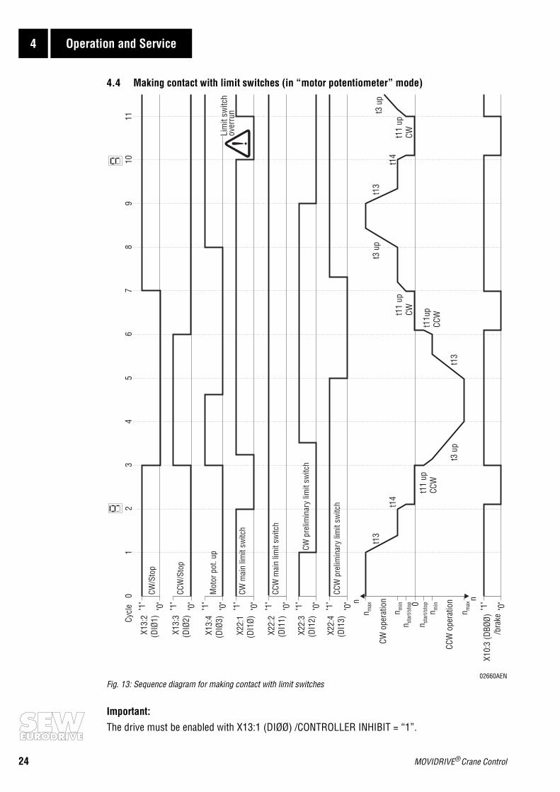
4.4 Making contact with limit switches (in “motor potentiometer” mode)
02660AENFig. 13: Sequence diagram for making contact with limit switches
Important:The drive must be enabled with X13:1 (DIØØ) /CONTROLLER INHIBIT = “1”.
nn
"0"
"0"
"0"
"0"
"1"
"1"
"1"
"1"
"1"
"1"
"0"
"0"0
n min
n max
n max
n min
01
23
45
67
89
1011
t13
t14
t13
t11u
pCC
W
t14
t13
n sta
rt/st
op
n sta
rt/st
op"1"
"0"
"1"
"0"
Mot
orpo
t.up
CCW
/Sto
p
CW/S
top
X10:
3(D
BØØ)
/bra
ke
X22:
4(D
I13)
X22:
1(D
I1Ø)
X13:
3(D
IØ2)
X13:
2(D
IØ1)
X13:
4(D
IØ3)
X22:
2(D
I11)
X22:
3(D
I12)
CWpr
elim
inar
ylim
itsw
itch
CCW
mai
nlim
itsw
itch
Lim
itsw
itch
over
run t3
up
t11
upCW
t3up
t11
upCW
t3up
t11
upCC
W
CCW
oper
atio
n
CWop
erat
ion
CCW
prel
imin
ary
limit
switc
h
CWm
ain
limit
switc
h
Cycl
e
MOVIDRIVE® Crane Control 25
Operation and Service 4
Explanation of the sequence diagram for making contact with limit switches(in motor potentiometer mode, also applies to fixed setpoint mode)
• Tl. X13:1 (DIØØ) /CONTROLLER INHIBIT = “1”
• Cycle 1: Tl. X13:2 (DIØ1) CW/stop = “1”, X13:3 (DIØ2) CCW/stop = “0”and X22:3 (DI12) CW preliminary limit switch from “1” to “0”
- Contact made with CW preliminary limit switch, so deceleration with ramp t13 until nmin.
• Cycle 2: Tl. X22:1 (DI1Ø) from “1” to “0”- Contact made with CW main limit switch, so deceleration with ramp t14 from nmin to nstart/
stop, then stop and X10:3 (DBØØ) /Brake from “1” to “0”, i.e. the brake is applied.The 7-segment display of the inverter shows “9” (contact made with limit switch).
• Cycle 3: Tl. X13:2 (DIØ1) CW/stop from “1” to “0”, X13:3 (DIØ2) CCW/stop from “0” to “1”and X13:4 (DIØ3) motor potentiometer up from “0” to “1”- CCW and tl. X10:3 (DBØØ) /Brake from “0” to “1”, i.e. the brake is released. Drive accelerates
with ramp t11 up CCW/until nmin and continues with ramp t3 up while as X13:4 = “1”.
• Cycle 4: Tl. X13:3 (DIØ2) CCW/stop = “1” and X13:4 (DIØ3) motor potentiometer up = “1”- nmax is reached, the drive is running at nmax.
• Cycle 5: Tl. X13:2 (DIØ1) CW/stop = “0”, X13:3 (DIØ2) CCW/stop = “1”and X22:4 (DI13) CCW preliminary limit switch from “1” to “0”- Contact made with CCW preliminary limit switch, so deceleration with ramp t13 until nmin.
• Cycle 6: Tl. X13:3 (DIØ2) CCW/stop from “1” to “0”
- Deceleration with ramp t11 down CCW from nmin to nstart/stop, then stop and X10:3 (DBØØ) /Brake from “1” to “0”, i.e. the brake is applied.
• Cycle 7: Tl. X13:2 (DIØ1) CW/stop from “0” to “1”
- Clockwise and tl. X10:3 (DBØØ) /Brake from “0” to “1”, i.e. the brake is released. Accelerationwith ramp t11 up CW until nmin.
• Cycle 8: Tl. X13:2 (DIØ1) CW/stop = “1” and X13:4 (DIØ3) motor pot. up from “0” to “1”
- Acceleration with motor potentiometer ramp t3 up as long as there is a “1” signal at X13:4.
• Cycle 9: X22:3 (DI12) CW preliminary limit switch from “1” to “0”
- Contact made with CW preliminary limit switch, so deceleration with ramp t13 until nmin
• Cycle 10: Tl. X22:1 (DI1Ø) from “1” to “0”- Contact made with CW main limit switch, so deceleration with ramp t14 from nmin to nstart/
stop, then stop and X10:3 (DBØØ) /Brake from “1” to “0”, i.e. the brake is applied.The 7-segment display of the inverter shows “9” (contact made with limit switch).
• Cycle 11: Drive past limit switch → tl. X22:1 (DI1Ø) CW main limit switch from ”0” to ”1”
- Important: Not an operational state. Drive moves past main limit switch and accelerates withramp t11 up CW until nmin and continues with ramp t3 up for as long as X13:4 = “1”.

26 MOVIDRIVE® Crane Control
4 Operation and Service
4.5 Fault messages
The limit switch monitoring function in the unit is active when the inverter is enabled, i.e. X13:1(DIØØ) /Controller inhibit = “1”. It checks that both preliminary and main limit switches are con-nected according to the wiring diagram (Fig. 2 on page 7 or Fig. 3 on page 8).
Limit switch inputs which are not in use must be connected to +24 V (X13:8 VO24), otherwise faultmessage F27 “Limit switches missing” is generated by the limit switch monitoring function.
The inverter is braked with the emergency stop ramp t14 if the main limit switches are missing orthere is an open circuit. Once the stop speed is reached, the brake is applied (DBØØ “/Brake” from“1” to “0”). The output stage goes to high-resistance after the brake reaction time has elapsed(P732 / P735). Error F27 is displayed on the 7-segment display. The plain text message “F27 Limitswitches missing” appears on the DBG11A keypad and in MX_SHELL.
Fault messages which occur are stored in fault memory P08_.
RESET: A fault message can be acknowledged by:
• Switching the mains power off and on again.Recommendation: Observe a minimum switch-off time of 10 s for the main contactor K11.
• Reset via input terminal, i.e. via an appropriately assigned binary input. The IPOSplus® programautomatically programs X22:5 (DI14) to the “RESET” function in the case of the crane control.
• Manual reset in MX_SHELL (P840 = “YES” or [Parameter] / [Manual reset])• Manual reset using the DBG11A (pressing the <E> key in the event of a fault gives direct access
to parameter P840)
Faultcode
Name Response P Possible cause Action
27 Limit swit-ches missing
Emergency stop
- Open circuit/both limit switches missing.
- Main limit switches swapped over in relation to motor sense of rotation
- Check wiring of limit switches.- Swap over main limit switch
connections.


SEW-EURODRIVE right around the globe isyour competent partner in matters of power
transmission with manufacturing and assem-bly plants in most major industrial countries.
We are available, wherever you need us.Worldwide.
SEW-EURODRIVE GmbH & Co · P.O.Box 30 23 · D-76642 Bruchsal/GermanyTel. +49-7251-75-0 · Fax +49-7251-75-19 70 · Telex 7 822 391http://www.SEW-EURODRIVE.com · [email protected]